methods of counting aircraft turbine...
TRANSCRIPT
TRANSACTIONS OF THE INSTITUTE OF AVIATION217, p. 5-13, Warsaw 2011
METHODS OF COUNTING AIRCRAFT TURBINE ENGINES
OPERATING CYCLES
RySzaRd ChaChuRSkI*, PaWeł GłoWaCkI**, StefaN SzCzeCIńSkI**
Military University of Technology*, Institute of Aviation**
Abstract
The issue of low-cycle fatigue is very important in terms of operational safety of aircraft turbine
engines. This paper discusses methods, which are used in US aviation industry to determine
boundary cycle counts, as well as methods of counting turbine engine operating cycles allowing
to determine the residual safe operation time (hard time), expressed in cycles. Methods are
discussed, which are used for both older types of engines as well as for present-day ones.
In the paper titled „Zmęczenie niskocyklowe konstrukcji i jego minimalizacja” (Low-cycle
structural fatigue and its minimization), published in volume no. 199/2009 of Prace Instytutu
Lotnictwa (Proceedings of the Institute of Aviation) contains a schematic presentation of loads
acting on components in the „hot section” of an aircraft turbine engine, as well as loads’
operational dependencies on engines’ operating conditions and operating ranges affecting their
low-cycle structural fatigue. The paper pointed out that findings related to this type of loads had
caused engine safe operation times to be expressed both in hours as well as in cycles. Methods for
determining the number of cycles „utilized” by main engine modules and their important parts
affecting operational safety, as well as maximum limits of operational cycle which if exceeded
should require replacement of respective modules or individual parts had been imposed on
operators by engine manufacturers. They are initially determined basing on fatigue tests
performed on standard specimens of structural material and then based on fatigue tests of
production parts and tests of complete engines. This paper is a further development of these
previously discussed topics.
Keywords: aircraft engine, turbine engine, low-cycle fatigue, cycles number
1. MethodS of the BouNdaRy CyCLe CouNt deteRMINatIoN
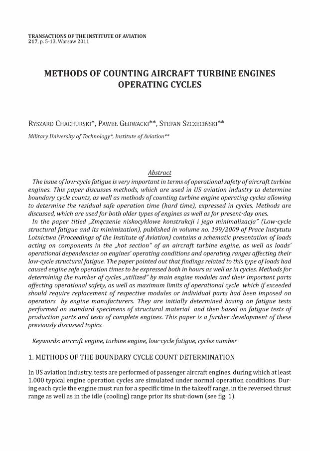
In uS aviation industry, tests are performed of passenger aircraft engines, during which at least1.000 typical engine operation cycles are simulated under normal operation conditions. dur-ing each cycle the engine must run for a specific time in the takeoff range, in the reversed thrustrange as well as in the idle (cooling) range prior its shut-down (see fig. 1).
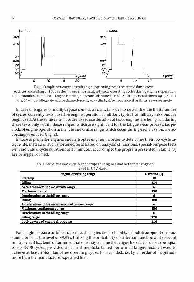
fig. 1. Sample passenger aircraft engine operating cycles recreated during tests (each test consisting of 1000 cycles) in order to simulate typical operating cycles during engine’s operationunder standard conditions. engine running ranges are identified as: r/c–start-up or cool-down, bjz–ground
idle, bjl – flight idle, pod– approach, zn–descent, wzn–climb, st/o–max. takeoff or thrust reverser mode
In case of engines of multipurpose combat aircraft, in order to determine the limit numberof cycles, currently tests based on engine operation conditions typical for military missions arebegin used. at the same time, in order to reduce duration of tests, engines are being run duringthese tests only within these ranges, which are significant for the fatigue wear process, i.e. pe-riods of engine operation in the idle and cruise range, which occur during each mission, are ac-cordingly reduced (fig. 2).
In case of propeller engines and helicopter engines, in order to determine their low-cycle fa-tigue life, instead of such shortened tests based on analysis of missions, special-purpose testswith individual cycle durations of 15 minutes, according to the program presented in tab. 1 [3]are being performed.
tab. 1. Steps of a low-cycle test of propeller engines and helicopter engines used in uS aviation
for a high-pressure turbine’s disk in such engine, the probability of fault-free operation is as-sumed to be at the level of 99.9%. utilizing the probability distribution function and relevantmultipliers, it has been determined that one may assume the fatigue life of such disk to be equalto e.g. 4000 cycles, provided that for three disks tested performed fatigue tests allowed toachieve at least 36630 fault-free operating cycles for each disk, i.e. by an order of magnitudemore than the manufacturer-specified life1.
6 RySzaRd ChaChuRSkI, PaWeł GłoWaCkI, StefaN SzCzeCIńSkI
this indicates that current methods for determining the safe number of fatigue cycles re-quire further test work and specifications.
zakres = range
fig. 2. a method of incorporating fatigue-related loads, based on the analysis of a combat aircraft engi-ne’s operating ranges in a typical mission (a) shortened engine test (b) example test corresponding toair combat (c) and combat support missions (d). engine operating ranges are identified as: bj – idling,
prz – cruising, max – maximum without afterburning, dop – maximum with afterburning
7MethodS of aIRCRaft eNGINeS oPeRatING CyCLeS CouNtING
1this indicates that current methods for determining the safe number of fatigue cyclesrequire further test work and specifications.
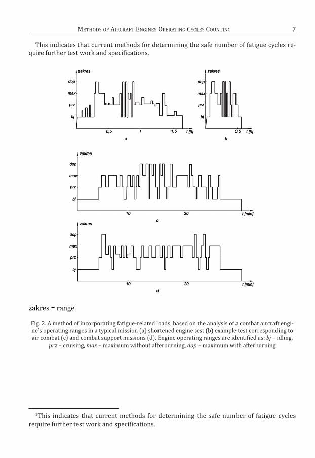
tab. 2 presents numbers of operating cycles which are being currently assumed during pre-liminary engine design stages, for various aircraft types in uSaf.
tab.2. Number of operating cycles currently assumed during engine preliminary design stages for various aircraft types in uSaf
the type I cycle referred to in the table involves engine start, reaching its maximum rangewithout afterburning or with afterburning followed by the engine shut-downtype III cycle in-volves transition from idling to maximum rev range without afterburning or with afterburningand return to the idling range. Whereas the type IV cycle involves a transition to the cruising revrange and to the maximum range, without afterburning and then return to the cruising range.
2. MethodS of eNGINe CyCLeS CouNtING
from the perspective of aircraft engine exploiters, it is necessary to precisely determinea method for counting operating cycles occurring during engine operation. a single, completeengine operating cycle shall be understood as its starting-up, transition to the maximum range(takeoff range) and shut-down. In case of commercial aircraft engines, during a single flight theengine, with all its parts in ambient temperature, is first started up and then for a brief mo-ment it warms up until temperature distribution of its parts and components stabilize and untilall clearances and fits between matching parts are brought up to standards. While taxing andwhile waiting for takeoff, the engine continues to run in its idle range or in a similar revs range.afterwards, during takeoff and climb phase of the flight it reaches its maximum or near-maxi-mum range. on the longest leg of the flight the engine runs within the cruising range, which isthen reduced during the descent and landing phases, finally reaching the idle range. In the finalphase of the engine operation, thrust reverser is enabled and then the aircraft taxis to the par-king area, where the engine is left to cool down, shut down and brought down to the ambienttemperature. for an engine operated in this regime, one may assume, by approximation, thatduring each flight one full operating cycle is performed.
In case of engines of multi-purpose combat aircraft, due to their different in-flight use re-gime, it is also necessary to take into consideration partial changes of engine parts' and as-semblies' loads, which are important values of the complete cycle. In aviation industries ofvarious countries, various methods for operating cycles counting are used.
In case of older engines, cycles are often counted „manually", by the technical staff, usingsimplified formulas or even using predefined cycle „utilization" values in relation to flight hour,depending on the aircraft mission (see tab. 3).
8 RySzaRd ChaChuRSkI, PaWeł GłoWaCkI, StefaN SzCzeCIńSkI
9MethodS of aIRCRaft eNGINeS oPeRatING CyCLeS CouNtING
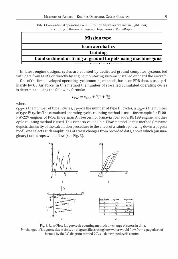
tab. 3. Conventional operating cycle utilization figures expressed in flight hour, according to the aircraft mission type. Source: Rolls-Royce
In latest engine designs, cycles are counted by dedicated ground computer systems fed with data from fdR’s or directly by engine monitoring systems installed onboard the aircraft.
one of the first developed operating cycle counting methods, based on fdR data, is used pri-marily by uS air force. In this method the number of so-called cumulated operating cycles is determined using the following formula:
where:cLCF–is the number of type I cycles, cFTC–is the number of type III cycles, a cCIC–is the numberof type IV cycles.the cumulated operating cycles counting method is used, for example for f100-PW-229 engines of f-16. In German air forces, for Panavia tornado's RB199 engine, anothercycle counting method is used. this is the so-called Rain-flow method. In this method (its namedepicts similarity of the calculation procedure to the effect of a raindrop flowing down a pagodaroof), one selects such amplitudes of stress changes from recorded data, above which (an ima-ginary) rain drops would flow (see fig. 3).
fig. 3. Rain-flow fatigue cycle counting method: a – change of stress in time,b – changes of fatigue cycles in time, c – diagram illustrating how water would flow from a pagoda roof
formed by the "a" diagram rotated 90˚, d – determined cycle counts
c cTAC LCF
c cFTC CIC= + +4 40

Water is poured on each fragment of an imaginary roof at its topmost point, whereas the partwhich extends the furthest is being considered first. from it water flows down to lower partsof the roof, until a point where it can freely reach the imaginary ground. the amplitude of thecycle stress is depicted by the horizontal distance between the initial point of a water drop andthe point where it reaches the earth. If a drop of water flowing from the next starting point doesnot flow off a piece of roof but it rather contributes to the water stream flowing from higherparts of the roof, then the stress amplitude is equal to the distance between the drop's startpoint and the point when it meets the water stream incoming from above.
another and somewhat simpler method of counting fatigue cycles is the so-called Reser-voir method, in which the graph of stress changes in time „is flooded with water" (see fig. 4) and then water is drained at its lowermost points (indicated on fig.4 with scissor symbols).
the height of the column of the water flowing out describes the cycle stress. By successively emptying the reservoir by releasing water at its lowermost points, the numberof cycles with stress amplitudes equal to heights of water columns in individual parts of the re-servoir is counted.
fig. 4. diagram illustrating the method of fatigue cycle counting in the so-called Reservoir method: σi – stress amplitude, t – time (scissors symbols indicate successive water draining” points)
Both methods produce the same results.for the RB199 engine an algorithm of low-cycle fatigue life calculation has been developed,
which utilizes in-flight recorded rotor speed.
first, the relative speed of the rotor is calculated as a fraction of the maximum speed without afterburning
next, using the Rain-flow method, minimum (nmin ) and maximum (nmax ) speed valuesare isolated for each cycle from the fdR. Next, for each cycle, its maximum and minimum stressvalues are calculated, which are proportional to respective rotational speeds:
nn
n=
100%
10 RySzaRd ChaChuRSkI, PaWeł GłoWaCkI, StefaN SzCzeCIńSkI
and then, threshold stress values are determined which correspond to the maximumpermitted speed ngr (e.g. such, at which the rotor would break apart) and maximum allowablestress values for an unlimited fatigue life (above 106 cycles) are calculatedwhere p is the value expressing the specified stress ratio of
Next, using the Goodman's formula, equivalent stress of a cycle is calculated:
then, damage value corresponding to a specific rotational speed of the rotor is determined:
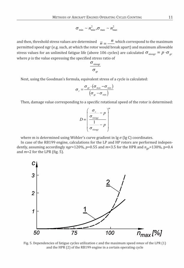
where m is determined using Wöhler's curve gradient in lg σ (lg C) coordinates.In case of the RB199 engine, calculations for the LP and hP rotors are performed indepen-
dently, assuming accordingly ngr=120%, p=0.55 and m=3.5 for the hPR and ngr=130%, p=0.4and m=2 for the LPR (fig. 5).
fig. 5. dependencies of fatigue cycles utilization c and the maximum speed nmax of the LPR (1) and the hPR (2) of the RB199 engine in a certain operating cycle
nn=
nieogr grp= ⋅
nieogr
gr
r
gr=−( )
−( )⋅ max min
gr min
D
p
p
r
m
=−
−
nieogr
nieogr
1
min min max max
, n n2 2
11MethodS of aIRCRaft eNGINeS oPeRatING CyCLeS CouNtING
the graphs shown on fig. 5 indicates, that for speeds of rotors lower than max., utilization offatigue cycles is higher for LPR’s than in case of hPR’s.
CoNCLuSIoN
awareness of fatigue life–related issues of aircraft turbine engine parts and methods of co-unting operational cycles utilized by such engines certainly has a significant impact on flight sa-fety. the choice of the correct engine operational cycle counting method becomes even moredifficult, as turbines in particular are subject to time-variable mechanical loads (resulting pri-marily from the rotational motion of rotor elements as well as from changes of their speeds),but also thermal ones due to uneven heating of their parts. another problem is that dependingon changes of the engine operating range, mechanical and thermal loads may be phase shiftedwith respect to each other.
In case of multi-rotor engines, utilization of fatigue cycles of each rotor is different and mustbe calculated independently. In operating ranges lower than max., hPR’s utilize less cycles thanLPR’s. It shall be expected that a specific methodology will be developed for determining thenumber of fatigue cycles safe for engine's structure, which would take into consideration flightconditions impacting temperature distribution in the most vulnerable engine parts (such as:turbine disks), and that means not just speed of rotors, but also their variable cooling perfor-mance, which depends on the altitude h and the speed V of an aircraft.
of course data on utilized cycles as well as forecasts regarding engine's continued safe ope-ration would depend on the design of each engine type–as the same airframe may be equippedwith many engine types. Many aircraft are designed with the option permitting installation ofvarious engines with similar specifications, e.g. on aircraft such as airbus or Boeing, enginesfrom Pratt&Whitney, Rolls-Royce or General electric (SNeCMa, CfMI, Iae) can be alternativelyused. the same applies in case of f-16, which may be equipped with various types of Pratt&Whitney f100 engines or General electric f110 engines.
BIBLIoGRaPhy
[1] Balicki W., Chachurski R., Szczeciński S., zmęczenie niskocyklowe konstrukcji i jego mini-malizacja (Low-cycle structural fatigue and its minimization), Prace Instytutu Lotnictwa(Proceedings of the Institute of aviation no. 199, Wydawnictwa Naukowe Instytutu Lot-nictwa (Institute of aviation' Scientific Publishing), Warsaw, 2009
[2] engine Structural Integrity Program (eNSIP), department of defence, 2002[3] Niepokólczycki a., fatigue of aircraft Structures, Institute of aviation, Warsaw, 2009[4] orkisz M. (red.), turbinowe silniki lotnicze w ujęciu problemowym (aircraft turbine en-
gines – Review of issues), PN-tte, Lublin, 2000[5] Pfoertner h., extension of the usable engine Life by Modelling and Monitoring, Rto aVt
Lecture Series on aging aircraft fleets: Structural and other Subsystem aspects, Sofia,2000
[6] Skalski J., ocena wpływu nieustalonych zakresów i warunków pracy turbinowego silnikaodrzutowego na wytrzymałość niskocyklową tarczy turbiny, (evaluation jet turbine en-gine transient ranges and operating conditions impacts on low-cycle life of turbine disk),Ph. d. thesis, Military university of technology, Warsaw , 1994
[7] Wiśniewski S., obciążenia cieplne silników turbinowych, (thermal loads of turbine engi-nes), Wkił, Warsaw, 1974
RySzaRd ChaChuRSkI, PaWeł GłoWaCkI, StefaN SzCzeCIńSkI12

MethodS of aIRCRaft eNGINeS oPeRatING CyCLeS CouNtING 13
[8] Vujić d., diagnostic system in aircraft engine maintenance, Scientific technical Review, Vol.LV, No. 1, Military technical Institute, Belgrad, 2005
[9] zoufaly B., obciążenia cieplne łopatek wieńca wirnikowego turbiny lotniczego silnika odrzutowego podczas rozruchu i akceleracji (thermal loads of aircraft jet engine turbinerim vanes during start-up and spool-up), Ph. d. thesis, Military university of technology,Warsaw, 1977
[10] technical descriptions and operating instructions of various types of engines.
RySzaRd ChaChuRSkI, PaWeł GłoWaCkI, StefaN SzCzeCIńSkI
METODY ZLICZANIA CYKLI PRACY LOTNICZYCH
SILNIKÓW TURBINOWYCH
Streszczenie
Zagadnienie zmęczenia niskocyklowego jest bardzo istotne z punktu widzenia bezpieczeństwa
eksploatacji lotniczych silników turbinowych. W artykule przedstawiono sposoby wyznaczania
granicznej liczby cykli stosowane w lotnictwie USA, a także metody zliczania cykli pracy silnika
turbinowego w celu określenia pozostałości czasu jego bezpiecznej eksploatacji (resursu) wyra-
żonego w cyklach. Opisano metody wykorzystywane podczas użytkowania zarówno silników star-
szych typów, jak i współczesnych.