on mass sensing using micro/nano …s2is.org/issues/v9/n1/papers/paper1.pdfon mass sensing using...
TRANSCRIPT

ON MASS SENSING USING MICRO/NANO RESONATORS -
APPROACHES, CHALLENGES AND DIRECTIONS
Bhaskar Choubey1 and Alistair McEwan2
1Department of Engineering Science
University of Oxford, Oxford, UK
Email: [email protected] of Electrical and Information Engineering
The University of Sydney, Sydney
Submitted: Dec. 14, 2015 Accepted: Jan. 1, 2016 Published: Mar. 1, 2016
Abstract- Micro/Nano electromechanical systems based Mass sensors are being increasingly used
for detecting very low masses, with significant applications in bio-sensing as well as environmental
sensing. A number of different shapes, excitation mechanisms as well as materials have been sug-
gested for these sensors. In addition, with reducing dimensions due to improvement in fabrication,
these sensors have the potential to measure bacterial level masses. This paper reviews some of the
research directions in this field. Various sensing and actuation strategies for these resonators are dis-
cussed. In addition, three important challenges, which have the potential of providing new directions
of research are also explored. These include quality factor, increasing nonlinearity and coupling.
Coupling of sensors can provide a unique opportunity to build several resonant sensors on the same
chip and reduce the number of contacts required as well as the potential bandwidth
Index Words - Microelectromechanical systems, Mass sensors, damping, nonlinearity, coupled systems
1
INTERNATIONAL JOURNAL ON SMART SENSING AND INTELLIGENT SYSTEMS VOL. 9, NO. 1, MARCH 2016

I. INTRODUCTION
There has been an increased interest in making sensors, which utilise micoelectromechanical
systems for measuring very low levels of mass or mass change [1, 2, 3, 4]. This has been further
advanced by improvements in nano-fabrication processes as well as discovery of new materials
like graphene recently [5], with claimed mass sensing abilities of zeptogram [6]. These highly
sensitive sensors offer immense potential for biosensing in future. Various approaches have
been used to measure mass with micro/nano devices, with resonator based techniques being
one of the most frequently used ones. In this paper, we review the approaches to mass sensing
using MEMS resonators along with various challenges being faced. Section II presents the
analysis of using MEMS resonators as mass sensors. Section III describes various options
available to a designer while designing such systems. Section IV explores three prominent
challenges as well as opportunities with reduction in feature sizes of these resonators. Finally,
section V provides the conclusion of the chapter.
II. MASS SENSING USING RESONATORS
To appreciate this measurement modality, let us consider a resonating mechanical structure.
Physically, this could take any form including mechanical beams, free at one end or clamped
at both ends or comb type structures. It could also have any sensing and actual mechanism
including electrostatic, piezoelectric, thermal or magnetic. A lumped model for any such device
can be expressed through the second order differential equation
mx+Bx+Ks = F (1)
where m is the mass of the resonator, B is a damping factor which depends on the medium and
Ks is the spring constant of the resonator. On application of a sinusoidal force with frequency
ω and amplitude F0, the response of the resonator can be obtained to be
x(t) = X(w) cos (wt− φ) (2)
2
Bhaskar Choubey and Alistair McEwan, ON MASS SENSING USING MICRO/NANO RESONATORS -APPROACHES, CHALLENGES AND DIRECTIONS

where the amplitude, X(ω), and the phase difference φ are [7]
X(w) =F/m[
(Ks/m− w2)2 + (ωB/m)2] (3)
φ = tan−1 wB/m
Ks/m− w2
In absence of damping, the resonance frequency of this system can be simplified to
w0 ≈√k
m(4)
Figure 1: (a) Shifts in resonance frequencies of the system with increase in damping (b) Phase
response of the system for different damping
The introduction of damping reduces the resonance frequency as shown in Figure 1, which
presents the magnitude response of a normalised resonator (Ks = 1,m = 1) with different
damping constants. It may be observed that for small changes in the damping, the resonance
frequency can be assumed to be constant. In such a resonator, with change in mass of δm, the
resonance frequency changes to
w20 =
k
m+ δm(5)
≈ w20 (1− δm/m)
Hence, the change in resonance frequency is approximately w0(δm/m)/2. This simple
equation illustrates the attractiveness of resonators for mass sensing. At one hand, the change
3
INTERNATIONAL JOURNAL ON SMART SENSING AND INTELLIGENT SYSTEMS VOL. 9, NO. 1, MARCH 2016
in the resonance frequency is directly proportional to the change in mass. This is useful as
frequency measurement techniques have been well established and noiseless measurements
of sub-hertz resolution are regularly carried. The phase response of the system for varying
damping, as shown in Figure 1(b) is very useful here, as the response undergoes a sharp 90o
change at the resonance frequency. This significantly simplifies the instrumentation required,
as rather than designing a peak amplitude detector, one can simply use a phase-locked detector
and monitor any change in the resonance frequency, and hence any change in the mass of the
system.
Second and more importantly, reducing the geometry of the devices would lead to reduction
in its mass, m, and therefore would improve the mass resolution of the sensors. With manu-
facturing dimensions reaching that of nano-meters, it is possible to make mass sensors with the
capability of measuring masses of pico and femto-grams levels. It is this reducing resolution,
which is attractive for biosensing, as with these resolutions, we are now reaching the mass do-
mains wherein small quantity of mass relevant to biological materials can be measured. With
an understanding of the physical foundation, we can now appreciate various physical options
we have in making biologically sensitive MEMS resonators.
III. DESIGN CHOICES
The measurement principal described in the previous section provides a number of opportuni-
ties for designing mass sensors. These also provide a number of different design choices, some
often linked with one another. First, a designer has to select the material from which the res-
onator will be made. This often also determines the materials which can be measured through
the resonating system. In addition, it is possible to functionalise the resonators and hence in-
crease the types of materials which can be measured. Once a material has been determined,
once has to decide about the excitation and measurement systems. These could include a num-
ber of different modalities including electrostatic, magnetic, thermal or piezoelectric systems.
Finally and often related to the excitation system, one has to design the resonator shape. This
section provides a review of these potentials without claiming to describe all potential designs,
as these will be difficult if not impossible to explain in a single paper.
4
Bhaskar Choubey and Alistair McEwan, ON MASS SENSING USING MICRO/NANO RESONATORS -APPROACHES, CHALLENGES AND DIRECTIONS

III.I. MATERIAL AND MEASURAND
Most micro/nano resonators utilise resonating structures made of biologically neutral materials.
For example, silicon or silicon dioxide is often preferred due to well-established micro/nano
fabrication facilities available on account of integrated circuit fabrication. Furthermore, silicon
is also very well studied and hence there is a good availability of models in various simula-
tion environments. The other options in a standard micro/nano fabrication process are to use
available metal including aluminium, copper, silver or gold. Polymers of different types have
also been used to make inexpensive resonators. Recently, new materials like graphene have
shown potential to make very small resonators thereby further enhancing the resolution of the
sensors [5].
However, most of these materials do not react well or react to a very few biochemical
substances. This means that by themselves, they cannot act as biosensors. However, suitable
functionalization with a reagent can enhance their bio-selectivity. There is a large number of
reagents-measurand pair, which can be used to functionalize the micro/nano resonator, a full
description of which will take significant space and is beyond the scope of the paper. Never-
theless, functionalization is a significant challenge for most resonator based sensors, including
mass sensors. At one hand, the dimension of the resonating structure is reducing to increase
the mass sensitivity. This means that the functionalisation area is being reduced. Furthermore,
the functionalization step is often not part of the regular micro/nano fabrication. This means
that it is carried out separately using a material dependant process. This also means that this
extra step often does not scale with the micro/nano fabrication, thereby introducing a challenge
in suitable functionalization. A suitable solution to this challenge would be to integrate the
functionalisation process with fabrication. However, there has been limited success in this till
date.
III.II. ACTUATION AND SENSING MECHANISM
Once all materials have been identified, the next task would be to select a suitable actuation
and sensing mechanism. Resonators are passive devices and hence they require application
5
INTERNATIONAL JOURNAL ON SMART SENSING AND INTELLIGENT SYSTEMS VOL. 9, NO. 1, MARCH 2016

of a force to induce resonance in them. Simultaneously, a mechanism is required to detect
the resonance in the system. The choices available to a system designer here are limited, yet
require careful consideration depending upon the material selected as well as the nature of the
end-product designed. Many a times, the excitation as well as the sensing mechanism could be
the same; however, it is also possible to have different mechanisms for actuation and sensing.
Different forces including that of thermal, magnetic, electrostatic and piezoelectric could
be used for excitation of the resonators. Thermally excited resonators act by passing a current
through the device, which produces heat on account of the inherent electrical resistance of the
device [8, 9]. Thermal actuation can provide large actuation forces for low electric voltage.
However, the thermal resonators are often slow actuators suitable only for very low frequency
applications. Further, due to thermal actuation, the parasitics and the ohmic loss is quite high
and the overall quality factor of the resonator reduces with time. Resonators designed from
magnetic materials can be magnetically actuated [10]. It eliminates the effects of charging or
stiction in small gaps often found in other actuation mechanism [11]. However, it is difficult
to miniaturise and often prone to external magnetic and electric forces.
Another technique that has been used to actuate the mass resonators is to use a piezoelectric
excitation. As one approach, travelling waves can be developed in a small slab of a piezoelectric
film and the changes in mass can be detected by observing its propagation characteristics [12].
As another approach, one can use piezoelectric forces to just excite the sensor and measure
through any other means. For example, Kumar and Bhaskaran utilise changes in resistance
to measure resonance while Choubey and co-workers have utilised optical means to measure
from the sensor [13]. As the resonators move, high speed imaging or vibrometry can be de-
ployed to measure resonance. Measuring in-plane resonance, however, is often very difficult.
Furthermore, integration of optical measurement system with the MEMS device is often very
challenging. In addition, piezoelectric transduction requires integration of piezoelectric thin
film with the micromechanical elements. Such integration usually results in a drastic decrease
in the resonator quality factor and could be impractical during the fabrication.
Yet another approach to excite resonators is to use electrostatic forces. These often utilise
capacitive devices, wherein the capacitance between two parts of a resonator or between res-
6
Bhaskar Choubey and Alistair McEwan, ON MASS SENSING USING MICRO/NANO RESONATORS -APPROACHES, CHALLENGES AND DIRECTIONS

onator and a fixed measuring surface changes with the movement of device. Often the capaci-
tance change introduced by a single capacitor is not enough to introduce large enough change
in signal level. Hence, large parallel structures with a number of a capacitances are often used
as shown in Figure 2[14].
Figure 2: (a) Comb resonators showing parallel capacitances increasing the throughput of the
system (b) An array of simple resonators, which move out of plane
III.III. RESONATOR SHAPES
As there are no standard structures in electro-mechanical systems, there is a wide variety in
physical shapes, which have been used as resonator structures. A complete review is beyond
the scope of this paper. However, we have already seen the use of comb structures. The physical
shape of the structure is often determined by the excitation and measurement system, ease of
manufacturing, damping, the mode in which measurement is required as well as often the
intellectual property of previous designs. The simplest resonating structure would be a simple
beam, anchored at one side. Figure 2(b) shows one such array of simple cantilevers wherein
the resonant motion is out of plane of the resonators (vertical to the substrate) [13]. These
structures generally excite the first mode of resonance. As an alternative, structures which are
7
INTERNATIONAL JOURNAL ON SMART SENSING AND INTELLIGENT SYSTEMS VOL. 9, NO. 1, MARCH 2016

clamped at both ends [5] or at multiple ends have also been used. Often low damping or better
frequency response and high sensitivity is claimed from these structures [15, 16]. In addition,
circular structures or structures which utilise rotational resonance have also been used [17].
IV. DESIGN CHALLENGES AND OPPORTUNITIES
We have explored various design choices in typical micro/nano resonator based sensors. We
will now consider three important design challenges and related opportunities when designing
these sensors at the nano-scale.
IV.I. QUALITY FACTOR
In all of our discussions till now, we have assumed that the resonators have high quality factors
and hence very low damping. This increases the amplitude at resonance, reduces the bandwidth
and simplifies the circuitry required to measure the response. To obtain high quality factor, one
needs to reduce the different sources of damping in the system. Damping is a collective measure
of various dissipation mechanism inside the resonator as well as its surrounding. A number of
factors affect the damping in a resonator. These include the material of resonator, its shape, its
operation mode and most importantly its environment [18].
The interaction between the structure of the resonator and its surrounding medium is one
of the foremost sources of damping, which is primarily due to the viscous damping by the fluid
surrounding the resonator. In addition, squeeze-film damping has also been known to affect
MEMS resonators [19]. A very simple technique, often employed in a number of experiments
with MEMS resonators to reduce the effect of damping, is to operate the device in very low air
pressure thereby reducing the viscous damping. While this does indeed reduce the damping, it
often fails to imitate the actual operational conditions. In addition, material damping also plays
a significant role in the operation of MEMS resonators. This often arises due to thermoeslastic
damping as well as internal friction due to crystal defects.
Studies have been reported which aim to either reduce the dissipation mechanism in the
resonators or increase the available energy [20]. In addition, a simple electronic technique to
improve the quality factor of single resonators is to provide electronic feedback and reduce the
8
Bhaskar Choubey and Alistair McEwan, ON MASS SENSING USING MICRO/NANO RESONATORS -APPROACHES, CHALLENGES AND DIRECTIONS

damping parameter as [21]
mx+Bx+Ksx = F +BFBx (6)
In any resonator system, either the displacement, x or the velocity x of the resonator is mea-
sured. It is hence possible, to provide a parametric excitation using an external amplifier, which
provides a gain of BFB. This will effectively reduce the effect of B in the resonator expression
and hence increase the quality factor.
However, when designing such systems, one has to ensure that the resultant damping B −
B+FB does not become negative, as this would introduce unwanted oscillations in the system
and would lead to significant instability. To appreciate the difficulty in designing such feedback
system, it is worth exploring a typical normalised system with very low quality factor and
hence high damping. To increase the quality factor by three orders of magnitude in a system
of normalised damping B of 1, one has to utilise BFB of 0.999 to lead to resultant damping
of 0.001. However, an error due to noise or otherwise of more than 0.1% in the feedback
path would lead to instability in the system. Hence, the feedback network has to be carefully
designed.
With biological mass measuring often utilised in liquid medium with unknown priori damp-
ing, quality factor control becomes even more challenging. The feedback network, hence has to
be designed with an automatic gain control mechanism. Furthermore, liquid media also intro-
duce second order nonlinearities on account of the viscosity as surface tension in the system.
This further complicates the design of the feedback mechanism. Nevertheless, an electronic
feedback can be a very simple mechanism to increase the quality factor of most resonating
biosensors.
IV.II. NONLINEARITY
Our discussion till now has been limited to linear sensors however as the size of individual
resonators reduces and the force applied does not reduce in the same proportion, these sensors
start showing increasing nonlinearity. This poses significant challenge all the sensor design as
practically most design principles as well as the related signal conditioning circuits are often
9
INTERNATIONAL JOURNAL ON SMART SENSING AND INTELLIGENT SYSTEMS VOL. 9, NO. 1, MARCH 2016
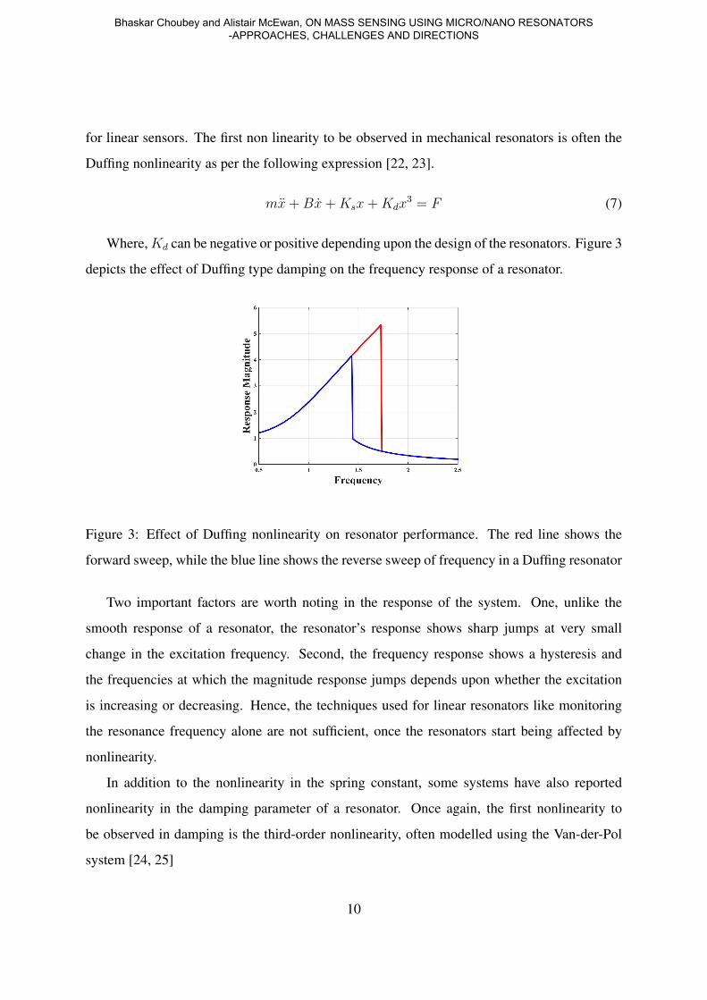
for linear sensors. The first non linearity to be observed in mechanical resonators is often the
Duffing nonlinearity as per the following expression [22, 23].
mx+Bx+Ksx+Kdx3 = F (7)
Where,Kd can be negative or positive depending upon the design of the resonators. Figure 3
depicts the effect of Duffing type damping on the frequency response of a resonator.
Figure 3: Effect of Duffing nonlinearity on resonator performance. The red line shows the
forward sweep, while the blue line shows the reverse sweep of frequency in a Duffing resonator
Two important factors are worth noting in the response of the system. One, unlike the
smooth response of a resonator, the resonator’s response shows sharp jumps at very small
change in the excitation frequency. Second, the frequency response shows a hysteresis and
the frequencies at which the magnitude response jumps depends upon whether the excitation
is increasing or decreasing. Hence, the techniques used for linear resonators like monitoring
the resonance frequency alone are not sufficient, once the resonators start being affected by
nonlinearity.
In addition to the nonlinearity in the spring constant, some systems have also reported
nonlinearity in the damping parameter of a resonator. Once again, the first nonlinearity to
be observed in damping is the third-order nonlinearity, often modelled using the Van-der-Pol
system [24, 25]
10
Bhaskar Choubey and Alistair McEwan, ON MASS SENSING USING MICRO/NANO RESONATORS -APPROACHES, CHALLENGES AND DIRECTIONS

mx+B(1 + νx2)x+Ksx = F (8)
The typical design approach with any systems showing nonlinearity is to ignore the nonlin-
earity and design resonators, which will be utilised at smaller applied forces, to ensure linear
response. However, the linear region of response available in nano electromechanical res-
onators is shrinking as the dimension of individual resonators is being reduced. Hence, this
increasing nonlinearity is introducing a significant challenge for designing low-dimensional
resonators. Nevertheless, it also provides an opportunity as the nonlinearity can provide differ-
ent and novel sensing paradigms. A simple approach to do so would be to operate the Duffing
resonator at a point just around the frequency its magnitude response jumps. With a very small
change in the mass, there will be a significant change in the response of the system. This will
hence, increase the sensitivity of the resonator significantly. However, due to inherent noise
in the system, it is often challenging to ensure the operation of resonators at this particular
frequency.
As the resonators size reduces, the effective nonlinearity observed will increase even further.
This will lead to introduction of even more complex terms in transfer function of the resonators.
Complete description of these nonlinearities is beyond the scope of the paper; however, it is
worth noting that though the increasing nonlinearity will lead to difficulties in designing simple
linear systems, it has the potential of introducing a number of new sensing modalities, which
may lead to innovating sensory solutions.
IV.III. MULTI-RESONATOR SYSTEMS
Our discussion has been limited to single resonators till now. Furthermore, the stated aim has
been to make them as small as possible to increase the mass sensitivity. This means that that
in modern micro- electromechanical sensors, it is possible to design more than one resonator
on the same trip. However, this is generally avoided, as this may lead to parasitic coupling
between the sensors and hence reduced sensitivity.
Nevertheless, this could provide two different potential approaches for improved sens-
ing [1, 13, 26]. A simple approach could be to just make a large number of smaller resonators
11
INTERNATIONAL JOURNAL ON SMART SENSING AND INTELLIGENT SYSTEMS VOL. 9, NO. 1, MARCH 2016

and add their output together. It is worth noting that that in any resonator based sensor, a sub-
stance is detected when it is absorbed on the surface of the sensor. However, the size of the
absorbing material is smaller than that of resonator. This also means that the total surface of
the resonator is not used to record the reagent. This suggests that rather than making one large
resonator, it may be beneficial to make several small resonators and connect their outputs to-
gether. To further appreciate this system with a typical example, let us consider, a system of
n mechanical resonators wherein the resonance frequency of each resonator is 20 KHz. The
resultant expression of the system would be
nmx+ nBx+ nKsx = Stimulus (9)
Figure 4: Response of a system of 5 identical resonators, each with a central frequency of
20KHz, when their responses are added together and when one of them changes its mass by
1%
The collective behaviour of the system can be shown by the response curve of Figure 4(a),
wherein the response of all resonators (5 in this case) have been added together. When any one
of the smaller resonator changes its mass, its resonance frequency will change by a factor of n
compared to that of a single large resonator. The effect of this can be observed in Figure 4(b),
wherein one of the resonator has changed its mass by 1%. A smaller peak due to this resonator
can be observed. The system can be measured by either monitoring the collective behaviour or
emergence of new resonant peaks.
12
Bhaskar Choubey and Alistair McEwan, ON MASS SENSING USING MICRO/NANO RESONATORS -APPROACHES, CHALLENGES AND DIRECTIONS
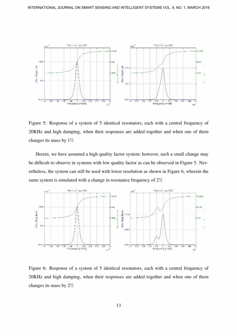
Figure 5: Response of a system of 5 identical resonators, each with a central frequency of
20KHz and high damping, when their responses are added together and when one of them
changes its mass by 1%
Herein, we have assumed a high quality factor system; however, such a small change may
be difficult to observe in systems with low quality factor as can be observed in Figure 5. Nev-
ertheless, the system can still be used with lower resolution as shown in Figure 6, wherein the
same system is simulated with a change in resonance frequency of 2%
Figure 6: Response of a system of 5 identical resonators, each with a central frequency of
20KHz and high damping, when their responses are added together and when one of them
changes its mass by 2%
13
INTERNATIONAL JOURNAL ON SMART SENSING AND INTELLIGENT SYSTEMS VOL. 9, NO. 1, MARCH 2016
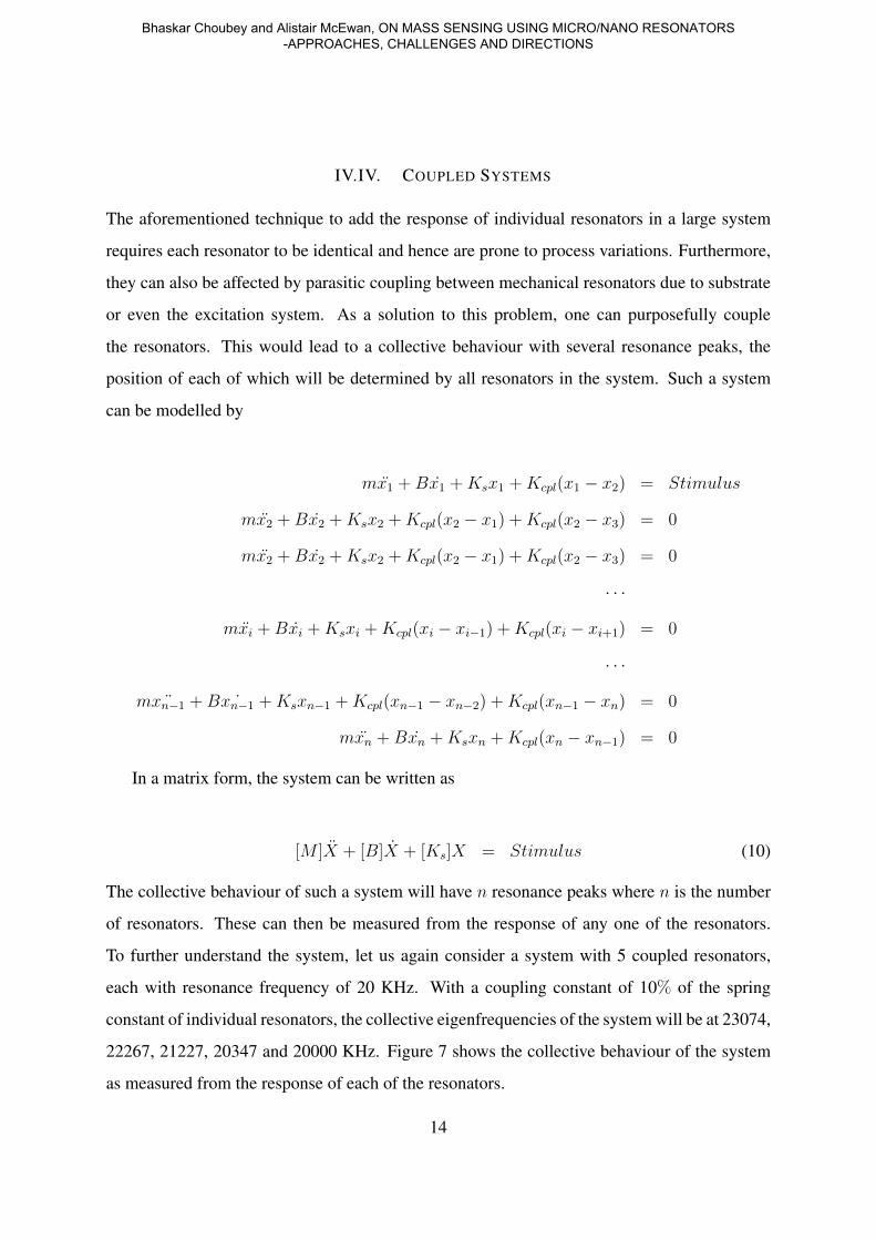
IV.IV. COUPLED SYSTEMS
The aforementioned technique to add the response of individual resonators in a large system
requires each resonator to be identical and hence are prone to process variations. Furthermore,
they can also be affected by parasitic coupling between mechanical resonators due to substrate
or even the excitation system. As a solution to this problem, one can purposefully couple
the resonators. This would lead to a collective behaviour with several resonance peaks, the
position of each of which will be determined by all resonators in the system. Such a system
can be modelled by
mx1 +Bx1 +Ksx1 +Kcpl(x1 − x2) = Stimulus
mx2 +Bx2 +Ksx2 +Kcpl(x2 − x1) +Kcpl(x2 − x3) = 0
mx2 +Bx2 +Ksx2 +Kcpl(x2 − x1) +Kcpl(x2 − x3) = 0
· · ·
mxi +Bxi +Ksxi +Kcpl(xi − xi−1) +Kcpl(xi − xi+1) = 0
· · ·
m ¨xn−1 +B ˙xn−1 +Ksxn−1 +Kcpl(xn−1 − xn−2) +Kcpl(xn−1 − xn) = 0
mxn +Bxn +Ksxn +Kcpl(xn − xn−1) = 0
In a matrix form, the system can be written as
[M ]X + [B]X + [Ks]X = Stimulus (10)
The collective behaviour of such a system will have n resonance peaks where n is the number
of resonators. These can then be measured from the response of any one of the resonators.
To further understand the system, let us again consider a system with 5 coupled resonators,
each with resonance frequency of 20 KHz. With a coupling constant of 10% of the spring
constant of individual resonators, the collective eigenfrequencies of the system will be at 23074,
22267, 21227, 20347 and 20000 KHz. Figure 7 shows the collective behaviour of the system
as measured from the response of each of the resonators.
14
Bhaskar Choubey and Alistair McEwan, ON MASS SENSING USING MICRO/NANO RESONATORS -APPROACHES, CHALLENGES AND DIRECTIONS

Figure 7: Modal response of all members of an array of resonators, each with a resonant fre-
quency of 20KHz, coupled through a spring constant which is 10 times weaker than individual
springs
15
INTERNATIONAL JOURNAL ON SMART SENSING AND INTELLIGENT SYSTEMS VOL. 9, NO. 1, MARCH 2016
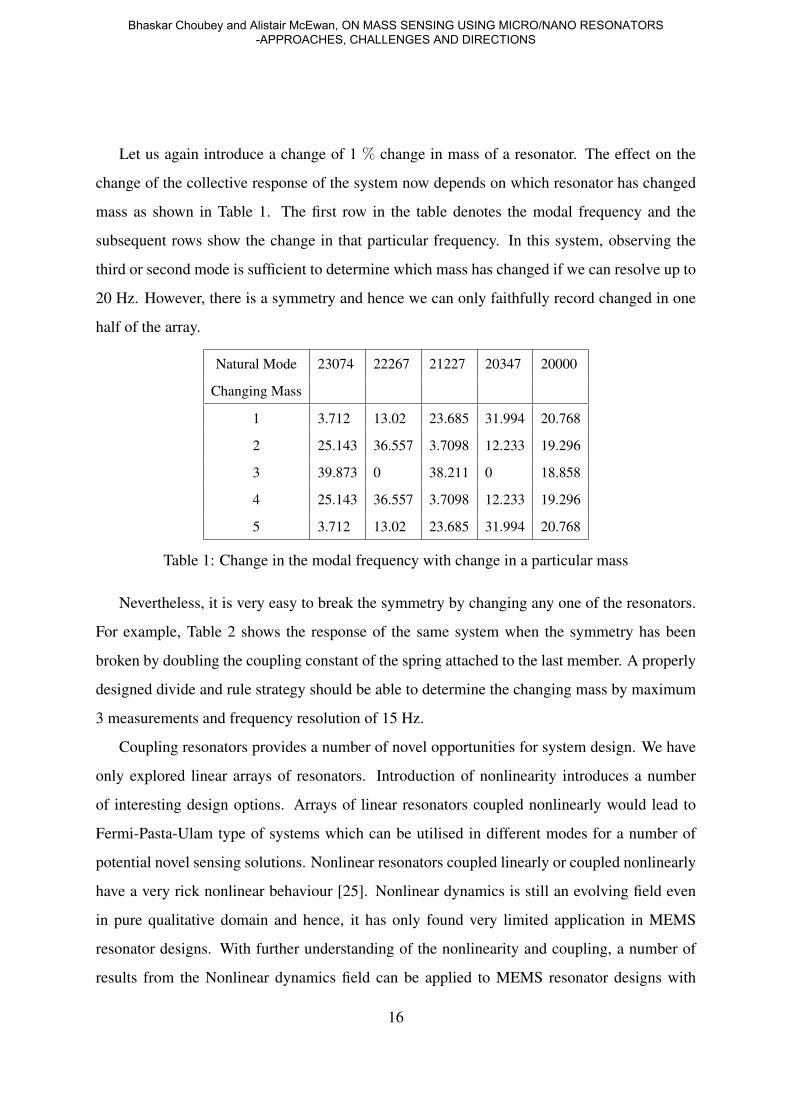
Let us again introduce a change of 1 % change in mass of a resonator. The effect on the
change of the collective response of the system now depends on which resonator has changed
mass as shown in Table 1. The first row in the table denotes the modal frequency and the
subsequent rows show the change in that particular frequency. In this system, observing the
third or second mode is sufficient to determine which mass has changed if we can resolve up to
20 Hz. However, there is a symmetry and hence we can only faithfully record changed in one
half of the array.
Natural Mode 23074 22267 21227 20347 20000
Changing Mass
1 3.712 13.02 23.685 31.994 20.768
2 25.143 36.557 3.7098 12.233 19.296
3 39.873 0 38.211 0 18.858
4 25.143 36.557 3.7098 12.233 19.296
5 3.712 13.02 23.685 31.994 20.768
Table 1: Change in the modal frequency with change in a particular mass
Nevertheless, it is very easy to break the symmetry by changing any one of the resonators.
For example, Table 2 shows the response of the same system when the symmetry has been
broken by doubling the coupling constant of the spring attached to the last member. A properly
designed divide and rule strategy should be able to determine the changing mass by maximum
3 measurements and frequency resolution of 15 Hz.
Coupling resonators provides a number of novel opportunities for system design. We have
only explored linear arrays of resonators. Introduction of nonlinearity introduces a number
of interesting design options. Arrays of linear resonators coupled nonlinearly would lead to
Fermi-Pasta-Ulam type of systems which can be utilised in different modes for a number of
potential novel sensing solutions. Nonlinear resonators coupled linearly or coupled nonlinearly
have a very rick nonlinear behaviour [25]. Nonlinear dynamics is still an evolving field even
in pure qualitative domain and hence, it has only found very limited application in MEMS
resonator designs. With further understanding of the nonlinearity and coupling, a number of
results from the Nonlinear dynamics field can be applied to MEMS resonator designs with
16
Bhaskar Choubey and Alistair McEwan, ON MASS SENSING USING MICRO/NANO RESONATORS -APPROACHES, CHALLENGES AND DIRECTIONS

enhanced sensing.
Natural Mode 23099 22329 21286 20369 20000
Changing Mass
1 1.3143 10.609 23.842 34.803 22.611
2 10.502 44.392 10.939 9.9675 21.139
3 25.702 11.138 38.003 1.2277 20.871
4 39.218 11.726 1.2769 22.948 21.7
5 21.622 22.363 21.419 20.602 10.937
Table 2: Change in the modal frequency with change in a particular mass. The coupling con-
stant attached to the last member has been doubled
V. CONCLUSION
Micro/nano resonators are increasingly being used for mass sensing, with particular importance
in biosensing. In this paper, we have reviewed various design choices available to build and use
these. As there are no standard shapes, sizes or actuation mechanism in the MEMS devices,
a large number of mass sensors have been proposed; however, it is this diversity, which often
leads to their poor ability to attract market popularity. We have also reviewed three principal
design challenges when designing resonators at nano-scale. These include the low quality fac-
tor, increasing nonlinearity and increasing coupling between devices. However, these provide
unique opportunities to utilise these higher order effects for enhanced sensing applications. Fur-
ther research is required to understand the effect of coupling and nonlinearity to make sensors
with enhanced sensitivity and fully utilise the potential of nano-sensors.
V. REFERENCES
[1] B. Choubey, C. Anthony, N. H. Saad, M. Ward, R. Turnbull, and S. Collins, “Character-
ization of coupled micro/nano resonators using inverse eigenvalue analysis,” Appl. Phys.
Lett., vol. 97, pp. 133 114–7, 2010.
17
INTERNATIONAL JOURNAL ON SMART SENSING AND INTELLIGENT SYSTEMS VOL. 9, NO. 1, MARCH 2016

[2] K. Park, N. Kim, D. Morisette, N. Aluru, and R. Bashir, “Resonant mems mass sensors
for measurement of microdroplet evaporation,” Microelectromechanical Systems, Journal
of, vol. 21, no. 3, pp. 702–711, June 2012.
[3] G. Blanco-Gomez and V. Agache, “Experimental study of energy dissipation in high qual-
ity factor hollow square plate mems resonators for liquid mass sensing,” Microelectrome-
chanical Systems, Journal of, vol. 21, no. 1, pp. 224–234, Feb 2012.
[4] A. Hajjam, J. Wilson, and S. Pourkamali, “Individual air-borne particle mass measure-
ment using high-frequency micromechanical resonators,” Sensors Journal, IEEE, vol. 11,
no. 11, pp. 2883–2890, Nov 2011.
[5] M. Kumar and H. Bhaskaran, “Ultrasensitive room-temperature piezoresistive transduc-
tion in graphene-based nanoelectromechanical systems,” Nano Letters, vol. 15, no. 4, pp.
2562–2567, 2015.
[6] Y. T. Yang, C. Callegari, X. L. Feng, K. L. Ekinci, , and M. L. Roukes, “Zeptogram-scale
nanomechanical mass sensing,” Nano Letters, vol. 6, no. 4, pp. 583–586, 2006.
[7] A. P. French, Vibrations and Waves. Chapman and Hall, 1971.
[8] A. Hajjam, A. Logan, and S. Pourkamali, “Doping-induced temperature compensation of
thermally actuated high-frequency silicon micromechanical resonators,” Microelectrome-
chanical Systems, Journal of, vol. 21, no. 3, pp. 681–687, June 2012.
[9] A. Hajjam, A. Rahafrooz, J. Wilson, and S. Pourkamali, “Thermally actuated mems res-
onant sensors for mass measurement of micro/nanoscale aerosol particles,” in Sensors,
2009 IEEE, October 2009, pp. 707 –710.
[10] A. Ozturk, H. Ocakli, N. Ozber, H. Urey, I. Kavakli, and B. Alaca, “A magnetically actu-
ated resonant mass sensor with integrated optical readout,” Photonics Technology Letters,
IEEE, vol. 20, no. 23, pp. 1905–1907, Dec 2008.
18
Bhaskar Choubey and Alistair McEwan, ON MASS SENSING USING MICRO/NANO RESONATORS -APPROACHES, CHALLENGES AND DIRECTIONS

[11] J. Verd, A. Uranga, G. Abadal, J. Teva, F. Torres, F. Prez-Murano, J. Fraxedas, J. Esteve,
and N. Barniol, “Monolithic mass sensor fabricated using a conventional technology with
attogram resolution in air conditions,” Applied Physics Letters, vol. 91, no. 1, 2007.
[12] G. L. Yeolho Lee and W. Moon, “A piezoelectric micro-cantilever bio-sensor using the
mass-micro-balancing technique with self-excitation.”
[13] B. Choubey, E. Boyd, I. Armstrong, and D. Uttamchandani, “Determination of the
anisotropy of young’s modulus using a coupled microcantilever array,” Microelectrome-
chanical Systems, Journal of, vol. 21, no. 5, pp. 1252–1260, Oct 2012.
[14] B. Choubey, S. Collins, and M. Ward, “On characterizing microelectromechanical pro-
cesses using coupled resonators,” Microelectromechanical Systems, Journal of, vol. 21,
no. 4, pp. 791–800, Aug 2012.
[15] J. Arcamone, G. Rius, G. Abadal, J. Teva, N. Barniol, and F. Perez-Murano, “Mi-
cro/nanomechanical resonators for distributed mass sensing with capacitive detection,”
Microelectronic Engineering, vol. 83, no. 4-9, pp. 1216 – 1220, 2006.
[16] R. Mestrom, R. Fey, J. van Beek, K. Phan, and H. Nijmeijer, “Modelling the dynamics of
a MEMS resonator: Simulations and experiments,” Sensors and Actuators A: Physical,
vol. 142, no. 1, pp. 306 – 315, 2008.
[17] A. K. Ismail, J. S. Burdess, A. J. Harris, G. Suarez, N. Keegan, J. A. Spoors, S. C. Chang,
C. J. McNeil, and J. Hedley, “The fabrication, characterization and testing of a mems cir-
cular diaphragm mass sensor,” Journal of Micromechanics and Microengineering, vol. 18,
no. 2, p. 025021, 2008.
[18] S. Joshi, S. Hung, and S. Vengallatore, “Design strategies for controlling damping in
micromechanical and nanomechanical resonators,” EPJ Techniques and Instrumentation,
vol. 1, no. 1, 2014.
[19] M. Bao and H. Yang, “Squeeze film air damping in {MEMS},” Sensors and Actuators A:
Physical, vol. 136, no. 1, pp. 3 – 27, 2007.
19
INTERNATIONAL JOURNAL ON SMART SENSING AND INTELLIGENT SYSTEMS VOL. 9, NO. 1, MARCH 2016

[20] Z. Davis, W. Svendsen, and A. Boisen, “Design, fabrication and testing of a novel MEMS
resonator for mass sensing applications,” Microelectronic Engineering, vol. 84, no. 5-8,
pp. 1601–1605, May 2007.
[21] C. Anthony, R. Turnbull, X. Wei, M. Ward, and S. Collins, “Fabrication and quality fac-
tor control of a microelectromechanical system resonator with linear differential drive,”
Science, Measurement Technology, IET, vol. 4, no. 4, pp. 206–213, July 2010.
[22] M. Agarwal, K. K. Park, R. Candler, B. Kim, M. Hopcroft, S. A. Chandorkar, C. Jha,
R. Melamud, T. Kenny, and B. Murmann, “Nonlinear characterization of electrostatic
mems resonators,” in International Frequency Control Symposium and Exposition, 2006
IEEE, June 2006, pp. 209–212.
[23] C. Deng and S. Collins, “The transient response of a duffing resonator following a param-
eter change,” in Circuits and Systems, 52nd IEEE International Midwest Symposium on,
Aug 2009, pp. 790–793.
[24] S. Zaitsev, O. Shtempluck, E. Buks, and O. Gottlieb, “Nonlinear damping in a microme-
chanical oscillator,” Nonlinear Dynamics, vol. 67, no. 1, pp. 859–883, 2012.
[25] B. Choubey, “An experimental investigation of coupled van der pol oscillators,” Transac-
tion of ASME, Journal of Vibration and Acoustics, vol. 132, p. 031013, 2010.
[26] B. Choubey, M. Ward, and S. Collins, “On readouts of multiple micro/nano resonator
sensors with mismatch,” in Proceedings of the IEEE Sensors Conference, 2008.
20
Bhaskar Choubey and Alistair McEwan, ON MASS SENSING USING MICRO/NANO RESONATORS -APPROACHES, CHALLENGES AND DIRECTIONS