onshore north perth basin well intervention activities ... north perth basin well intervention...
TRANSCRIPT

DOCUMENT NO HSE-E-075-SUM
REVISION A
DATE OF REVISION 06/01/2014
Onshore North Perth Basin Well Intervention Activities
Environment Plan Summary

Onshore North Perth Basin Well Intervention Activities Environment Plan Summary
Page 2 of 12
TABLE OF CONTENTS 1.0 PURPOSE ........................................................................................................................... 4
2.0 INTRODUCTION ................................................................................................................. 4
3.0 ACTIVITY LOCATION ......................................................................................................... 5
4.0 GENERAL DESCRIPTION OF EXISTING ENVIRONMENT ............................................. 11
4.1.1 Natural Environment ..................................................................................... 11
4.1.2 Surface and Groundwater Systems ............................................................... 11
4.1.3 Social Environment ....................................................................................... 12 5.0 DESCRIPTION OF THE ACTIVITY ................................................................................... 12
5.1.1 Possible Modifications to Wellsite ................................................................. 13
5.1.2 Mobilisation of Equipment, Personnel and Supplies ...................................... 13
5.1.3 Conducting Well Intervention Activities .......................................................... 14
5.1.4 Pumping ........................................................................................................ 15 5.1.5 Wellhead Maintenance ................................................................................ 15
5.1.6 Pulling and Replacing a Completion ......................................................... 15
5.1.7 Slickline Operations .................................................................................... 15
5.1.8 Wireline Operations .................................................................................... 16
5.1.9 Snubbing ..................................................................................................... 16
5.1.10 Coiled Tubing .............................................................................................. 16
5.1.11 Well Testing ................................................................................................. 17
5.1.12 Remedial Cement Squeezing ..................................................................... 17
5.1.13 Plug and Abandonment Activities ............................................................. 17
5.1.14 Demobilisation .............................................................................................. 18
5.1.15 Rehabilitation ................................................................................................ 18
5.1.16 Utilities and Services ..................................................................................... 19 5.1.17 Water ............................................................................................................ 19
5.1.18 Communications ......................................................................................... 19
5.1.19 Electricity ..................................................................................................... 19
5.1.20 Offices and Storage Areas ......................................................................... 19
5.1.21 Waste Disposal ........................................................................................... 19
5.1.22 Weed and Dieback Hygiene Procedure ..................................................... 20
5.1.23 Chemical Disclosure ................................................................................... 20
6.0 MAJOR ENVIRONMENTAL HAZARDS AND CONTROLS .............................................. 21
7.0 MANAGEMENT APPROACH ........................................................................................... 21
8.0 CONSULTATION .............................................................................................................. 22
9.0 REPORTING ..................................................................................................................... 23
10.0 CONTACT DETAILS ......................................................................................................... 24
LIST OF FIGURES
Figure 1 Map of AWE’s Perth Basin Permits and Producing Fields ............................................. 6

Onshore North Perth Basin Well Intervention Activities Environment Plan Summary
Page 3 of 12
Figure 2 Map of Potential Wells to be intervened in the L1 (Hovea Area) ................................... 7
Figure 3 Map of Potential Wells to be intervened in the L1 (Dongara) and L2 ............................. 8
Figure 4 Map of Potential Wells to be intervened in L7 (Mount Horner) ...................................... 9
Figure 5 Map of Potential Wells to be intervened in L4 and L5 (Woodada) ............................... 10
LIST OF TABLES Table 1 Summary of Well Intervention Activities stakeholder engagement .............................. 22
LIST OF ATTACHMENTS Attachment 1. ............................................................................... WIA Generic Chemical Summary
Attachment 2. ....................................................................................... Material Safety Data Sheets
Attachment 3. ......................................................................... WIA Environmental Risk Assessment

Onshore North Perth Basin Well Intervention Activities Environment Plan Summary
Page 4 of 12
1.0 PURPOSE
The purpose of this document is to provide a summary of the Onshore North Perth Basin Well Intervention Activities Environment Plan [HSE-E-075] which was approved in part subject to the approval Oil Spill Contingency Plan (OSCP) on 16th December 2013.
Under sub regulation 11 (7) of the Petroleum and Geothermal Energy Resources (Environment) Regulations 2012, it is a requirement to submit a summary of the aforementioned Environment Plan to the Department of Mines and Petroleum for public disclosure within 10 days of receiving approval notification.
2.0 INTRODUCTION
ARC Energy Limited (“ARC”) or the newly renamed AWE Perth Pty Ltd is a wholly owned subsidiary of AWE Limited (“AWE”).
AWE is an Australian based oil and gas exploration and production company. AWE currently has oil and gas interests in Australia, New Zealand, Indonesia and the USA and is actively reviewing additional growth opportunities.
AWE produces gas and oil from onshore Oil and Gas Fields in the Perth Basin and has an active onshore exploration program. AWE has a Sydney head office with a Western Region Office in Perth and Perth Basin field operations at the Hovea Production Facility (HPF), Dongara Production Facility (DPF), Woodada Gas Field (WGF) and Mt Horner Oil Field (MHOF). AWE has contracted the operation of these facilities to Oceaneering Field Operations in the Perth Basin.
Perth Basin WIAs are managed by the AWE Operations Supervisor (office) and Well Services Engineer (field).
The scope of this document includes the environmental aspects of all Onshore North Perth Basin WIAs (Figure 1 and 2). The key activities include:
• Possible modifications to the existing well site pad area to ensure the ground is capable of supporting the WIA, and ancillary equipment
• Mobilisation of WIA Equipment, personnel and supplies • Conducting the WIA • Demobilisation of WIA Equipment, personnel and supplies • Restoration of the site following the completion of activities

Onshore North Perth Basin Well Intervention Activities Environment Plan Summary
Page 5 of 12
3.0 ACTIVITY LOCATION
There are potentially 73 wells (plus any new drilled wells) that could be worked over in the North Perth Basin. 62 of these wells are located on cleared farmland; and 11 are located within Nature Reserve. A map has been created for potential WIA locations within petroleum licence areas:
• L1 (Hovea Area) (22 potential wells) Apium-02, Centella-01, Drakea-02, Evandra-02, Eremia-01, 02, 04, 06 and 07, Hovea-01, 02, 03, 04, 07, 08, 10, 11, 12 and 13, Snottygobble-01, Xyris-01 and Xyris South-01
• L1 (Dongara Area) and L2 (28 potential wells) Corybas-01, Dongara-01, 03, 04, 09,10, 11, 12, 18, 19, 20, 21, 22, 23, 24, 25, 28, 31, 32, 33, 34, 35, 36 and 37, Senecio-02, Yardarino-01, 06 and the DPF Service Well (WDW).
• L4 and L5 (15 potential wells) East Lake Logue 01 and 02, Indoon-01, Woodada-02, 05, 06, 08, 10, 11, 12, 14, 15, 16 and 19, and Woodada Deep-01.
• L7 (8 potential wells) Mount Horner-04, 04A, 05A, 07, 08, 09, 12, 14 Wells within Nature Reserves are Drakea-02, East Lake Logue 01 & 02, Woodada-06, 08, 11, 12, 14, 15, 16 and 19, and Woodada Deep-01.
Wells within Environmentally Sensitive Areas are East Lake Logue 01 & 02, Woodada-06, 08, 11, 12, 14, 15, and 16 and Woodada Deep-01.
Of the 73 wells that could potentially be worked over 44 are >1 km from a surface water body. Where a well is in close proximity to a surface water body, management measures are put in place to ensure there is no impact on the water body including orientation of equipment and chemicals.
The activities listed in Section 5.0 could potentially be conducted on all wells in the Onshore North Perth Basin.
This Environment Plan supersedes the Environmental Management Plan for Onshore North Perth Basin Well Intervention Activities (21/HSEQ/ENV/PL01).

Onshore North Perth Basin Well Intervention Activities Environment Plan Summary
Page 6 of 12
Figure 1 Map of AWE’s Perth Basin Permits and Producing Fields

Onshore North Perth Basin Well Intervention Activities Environment Plan Summary
Page 7 of 12
Figure 2 Map of Potential Wells to be intervened in the L1 (Hovea Area)

Onshore North Perth Basin Well Intervention Activities Environment Plan Summary
Page 8 of 12
Figure 3 Map of Potential Wells to be intervened in the L1 (Dongara) and L2

Onshore North Perth Basin Well Intervention Activities Environment Plan Summary
Page 9 of 12
Figure 4 Map of Potential Wells to be intervened in L7 (Mount Horner)

Onshore North Perth Basin Well Intervention Activities Environment Plan Summary
Page 10 of 12
Figure 5 Map of Potential Wells to be intervened in L4 and L5 (Woodada)

Onshore North Perth Basin Well Intervention Activities Environment Plan Summary
Page 11 of 12
4.0 GENERAL DESCRIPTION OF EXISTING ENVIRONMENT
4.1.1 Natural Environment
The proposed activity is located within private farm land in the North Perth Basin. The North Perth Basin has a Mediterranean-type climate characterised by seasonal patterns of hot, dry summers and mild, wet winters. The area is subject to high wind speeds, dust storms, lightning storms, high summer temperatures and low winter night temperatures.
Annual rainfall averages approximately 465 mm near the coast but tapers off to around 335 mm 100 km inland. Generally 55% of annual rainfall occurs between April and September with the wetter months being June and July.
The soils consist of calcareous and siliceous sand underlain by aeolianite, which is often exposed. The North Perth Basin is situated entirely within the Geraldton Sandplains Biogeographical Region. Within this region, three broad physiographical units are recognised; the Swan Coastal Plain, the Arrowsmith Region and the Dandaragan Plateau. The areas in which WIA will be undertaken will generally be located entirely within the Swan Coastal Plain unit, which forms an elongated strip approximately 40km wide running along the coast.
Groundwater and surface water drainage is westward but the Irwin River valley to the north of the region is the only major coordinated drainage indentation. A number of swamps surrounded by dense scrub, frequent limestone outcrops and the occasional laterite outcrop are the other major features in the region. The sub-surface geology of the area consists of the Late Jurassic Yarragadee Formation, which is overlain by Tertiary Sediments. Groundwater is present in the Tertiary Sediments and the Yarragadee Formation, and the groundwater level is near, or at surface in the aforementioned swamps and low lying areas, following the surface topography, but with lower relief.
The North Perth Basin is located within the Irwin Botanical District (Northern Sandplains Region), within the Southwest Botanical Province as defined by Beard (1976). Under the Interim Biogeographic Regionalisation for Australia (IBRA) (Environment Australia 2000), the area lies on the Geraldton Sandplain, which is described as ‘mainly proteaceous scrub-heaths, rich in endemics, on the sandy earths of an extensive, undulating, lateritic sandplain mantling Permian to Cretaceous strata’.
4.1.2 Surface and Groundwater Systems
The hydrology of the region is dominated by the landform units described above. Drainage is westward but the Irwin River valley to the north of the region is the only major coordinated drainage indentation. A number of swamps surrounded by dense scrub, frequent limestone outcrops and the occasional laterite outcrop are the other major features in the region. The sub-surface geology of the area consists of the Late Jurassic Yarragadee Formation, which is overlain by Tertiary Sediments. Groundwater is present in the Tertiary Sediments and the Yarragadee Formation, and the groundwater level is near, or at surface in the aforementioned swamps and low lying areas, following the surface topography, but with lower relief. The porous and permeable coastal limestone and dune systems tend to

Onshore North Perth Basin Well Intervention Activities Environment Plan Summary
Page 12 of 12
allow rainwater to percolate vertically to the water table rather than running laterally off the surface. Various smaller channels exist to the south of the region including Stockyard Gully and Eneabba Creek flowing into Stockyard Gully Cave and Lake Logue. After exceptional rainfall these drainage flows cause extensive flooding. The natural hydrological flow in the south of the region has been altered due to artificial drain construction and extensive clearing in the catchments of Stockyard Gully and Eneabba Creek. This has resulted in increased runoff and rising salt in the region, changing the quantity and quality of water flow into Stockyard Gully and Lake Indoon.
4.1.3 Social Environment
The surroundings are populated region with limited settlement, transport or communications infrastructure. The townships of Dongara/Port Denison, Mingenew and Eneabba are the largest population centres in the vicinity of the proposal.
The region is relatively undeveloped, comprising of small coastal settlements that are economically dependent on fishing, agriculture, tourism, mining and natural gas / oil production. Dongara/Port Denison is a rock lobster fishing port.
Land use within the surrounding region is pastoral, consisting of wheat, sheep and cattle farming. The bushland areas of the region support seasonal honey production and commercial wildflower harvesting.
The Hovea 10 well site is located on cleared farmland as depicted within Figure 1. The site is located approximately 1 km south of the Hovea Production Facility, which is currently under Care and Maintenance.
Land use within the surrounding region is pastoral, consisting of wheat, sheep and cattle farming. The bushland areas of the region support seasonal honey production and commercial wildflower harvesting.
The nearest sensitivities include the Bonny Rock Transport camp, located immediately west of the Hovea Production Facility (refer to Figure 1).
There are no sensitive areas within the immediate vicinity of the Hovea-10 well site.
5.0 DESCRIPTION OF THE ACTIVITY
The scope of this document includes the environmental aspects of all Onshore North Perth Basin WIA (Figure 1 and 2). It is important to note Onshore Perth Basin WIA’s are ongoing.
General Well Intervention Activities (WIA) not requiring injection of down-hole chemicals will operate under this EP and not require submission of a Bridging EP (Summary) Document. General WIA may include the following:
• Well site preparation on existing leases that do not require a clearing permit • Well Head Maintenance • Wire line Operations • Pulling and replacing a completion • Snubbing
Onshore North Perth Basin Well Intervention Activities Environment Plan Summary
Page 13 of 12
WIA’s that require injection of chemicals or substances ‘down-hole’ will trigger Bridging EP (Summary) document development, includes (but not limited to the following):
• Well site preparation on existing leases that requires a clearing permit • Acid wash treatments • Plug and Abandonment • Wax dissolver treatments • Remedial cement squeezing • Coiled Tubing The key activities include:
• Possible modifications to the existing well site area to ensure the ground is capable of supporting the WIA Equipment (this may include water pond/s, retention pond and flare pit)
• Mobilisation of WIA Equipment, personnel and supplies • Conducting the WIA (as described in section 5.1.3) • Demobilisation of WIA Equipment, personnel and supplies • Restoration of the site following the completion of activities
5.1.1 Possible Modifications to Wellsite
Well sites in the North Perth Basin vary in size from 90 m x 90 m up to 135 m x 135 m. At some locations, the site required for the WIA may need to be levelled and construction of a water pond, retention pond and flare pit. Flare pit will be compacted and clay-lined (10-9m/s infiltration rate), chemical bund and the retention pond will be lined with HDPE liners.
No clearing is required at 62 of the wells where WIA could be conducted. The other wells are within the Woodada Gas Field (11) and Drakea Exploration Well (1). Clearing to the extent which has been cleared before within the Woodada Gas field can be conducted under Clearing Permit CPS3318. This permit covers track and wellsite cleared area maintenance. The vegetation that would potentially be cleared is regrowth on the existing gravel tracks and wellsites and not remnant vegetation. A clearing permit is not required for the Drakea site where the clearing is to the extent cleared previously.
5.1.2 Mobilisation of Equipment, Personnel and Supplies
The WIA equipment, personnel and supplies are mobilised by road to the WIA site. The workforce is accommodated in the nearest camp location or town (Dongara or Eneabba) which has the required accommodation.
The workforce drives to the well site each day, usually using a total of 2-3 vehicles. A minimum of one vehicle is required on site when personnel are on site.
A portable self-contained toilet is hired for use when on remote locations. The portable toilet is serviced by the leaser and all effluent is removed offsite.
Water is supplied to the well site from mobile water tankers
Diesel fuel is delivered by mobile diesel tank (mounted on a 4WD vehicle) to diesel tanks on site.

Onshore North Perth Basin Well Intervention Activities Environment Plan Summary
Page 14 of 12
Refuelling will occur at the WIA site. For small WIA, if refuelling is required, it will be via a vehicle mounted diesel tank. For larger WIA, an onsite diesel tanker trailer is set up for refuelling.
5.1.3 Conducting Well Intervention Activities
WIA are remedial operations undertaken by AWE to maintain maximum oil or gas producing rates and well integrity. WIA are any operation carried out on an oil or gas well during, or at the end of its productive life, that alters the state of the well and or well geometry, provides well diagnostics or manages the production of the well. The types of WIA conducted on the Perth Basin Production facilities can be summarised as follows:
• General WIA
o Wellhead Maintenance
o Pulling and Replacing a Completion
o Slickline
o Wireline (cabling)
o Snubbing
o Well Testing
• WIA requiring down-hole injection
o Pumping
o Remedial Cement Squeezing
o Plug and Abandonment
o Coiled tubing WIA generally runs for approximately 14 days, which includes the mobilisation / demobilisation time. Noise and light disturbance to surrounding landowners is not generally a concern due to the remote location of the wells. However, if noise disturbances are considered likely to occur, the AWE WIA Supervisor will request consultation with the relevant affected landowner.
• A blow out preventer (BOP) is used during WIA (if required). Low pressure WIA may not necessitate a BOP.
• If well testing during or after the WIA is required, a purpose built compacted clay-lined (10-9m/s infiltration rate) flare pit may be constructed. If flaring is required in the restricted burning period, a Bush Fires Act 1954 Section 25A permit will be applied for from the Department of Fire and Emergency Services (DFES). Any clearing that requires regulatory approval will trigger an Environmental Plan Bridging Document submission to the relevant regulatory bodies for approval.
• The Perth Basin Production Facilities as described in the Safety Case facility descriptions (21/HSEQ/GEN/PL03) require periodic WIA.
• An environmental audit of WIA is to be carried out annually. A pre-start safety and environmental meeting is held with all crew and other stakeholders, prior to commencing WIA. The WIA crew are required to undergo a RapidInduct induction annually.

Onshore North Perth Basin Well Intervention Activities Environment Plan Summary
Page 15 of 12
5.1.4 Pumping
This is the simplest form of intervention, as it does not involve putting hardware into the well itself. Frequently it simply involves rigging up to the kill wing valve on the Xmas tree and pumping liquid and chemicals into the well using a pump, generally a Gardner Denver P#5 triplex pump. This may consist of: • Well Control Inhibited Liquid • Diluted Acid with Water • Cement Slurry • Wax Dissolver
5.1.5 Wellhead Maintenance
The complexity of this operation can vary depending on the condition of the wellhead. Scheduled annual maintenance may simply involve greasing and pressure testing the valve on the hardware using a grease trailer and high pressure pump.
5.1.6 Pulling and Replacing a Completion
Involves pulling and replacing a completion with a workover rig or jacking platform with associated workover equipment such as crane, pressure control equipment and tanks. For some sucker rod pumping wells, a wax dissolver chemical may be used to dissolve the wax prior to pulling the down-hole pump.
5.1.7 Slickline Operations
Slickline operations may be used for fishing, gauge cutting, setting or removing plugs, deploying or removing wireline retrievable valves and memory logging. Slickline units use long, smooth, unbraided wire, often shiny, silver/chrome in appearance. It comes in varying lengths, according to the depth of the well. The unbraided wire is spooled off a drum on the back of a slickline truck to use down hole tools in the well. The tools lowered into an oil or gas well are used to perform a specified maintenance job down hole. Slickline units may require a crane to lift the lubricator. The slickline operator monitors at surface the slickline tension via a weight indicator gauge and the depth via a depth counter 'zeroed' from surface to ensure the down hole tool is lowered to the desired depth. The job is completed by manipulating the down hole tool mechanically. Checks are undertaken to ensure the job has been completed (if possible), and then pulls the tool back out by winding the slickline back onto the drum it was spooled from. The slickline drum is controlled by a hydraulic pump, which is controlled by the operator. Slickline comes in different sizes and grades. The larger the size, and higher the grade, generally means the higher line tension can be pulled before the line snaps at the weakest spot and causes a costly 'fishing' job.

Onshore North Perth Basin Well Intervention Activities Environment Plan Summary
Page 16 of 12
5.1.8 Wireline Operations
The term wireline usually refers to cabling technology used by operators of oil and gas wells to lower equipment or measurement devices into the well for the purposes of WIA and reservoir evaluation. Braided line can contain an inner core of insulated wires which provide power to equipment located at the end of the cable, normally referred to as electric line, and provides a pathway for electrical telemetry for communication between the surface and equipment at the end of the cable. Occasionally braided line is used for swabbing operations where liquid is removed from the well. The wireline apparatus resides on the surface, wound around a large portable spool on the back of a special truck. A motor and drive train turn the spool and raise and lower the equipment into and out of the well. Wireline units may require a crane to lift the lubricator.
5.1.9 Snubbing
Also known as a Hydraulic Workover, this involves forcing a string of pipe into the well against wellbore pressure to perform the required tasks. The rig-up is larger than for coiled tubing and the pipe more rigid. Snubbing involves running the BHA on a pipe string using a Hydraulic Workover Rig. Unlike wireline or coiled tubing, the pipe is not spooled off a drum but made up and broken up while running in and pulling out, much like conventional drill pipe. A snubbing rig-up is a very tall structure. It consists of a hydraulically powered snubbing unit, which provides the force on a pipe, above a string of multi-layered pressure control components. Due to the large rig-up, it is generally only used for the more demanding of operations when lighter intervention techniques do not offer the strength and durability. Unlike conventional drilling and completions operations, snubbing can be performed with the well still under pressure.
5.1.10 Coiled Tubing
Coiled tubing refers to metal piping, normally 25mm to 83mm (1" to 3.25") in diameter, used for interventions in oil and gas wells and comes spooled on a large reel. Coiled tubing is often used to carry out operations similar to wire lining. A coiled tubing operation can be run by a mobile self-contained coiled tubing unit or a smaller service rig. Coil tubing is also used to perform open-hole milling operations. This has the advantage of requiring less effort to trip in and out of the well (the coil can simply be run in and pulled out while drill string must be assembled and dismantled joint by joint while tripping in and out). Additionally, the coiled tubing is tripped into and out of hole, providing a hermetic seal around the coil allowing the well to flow during drilling operations. Instead of rotating the drill bit by using a rotary table or top drive at the surface, it is turned by a downhole motor, powered by the motion of drilling fluid pumped from surface. Because coiled tubing is rigid, it can be pushed into the well from the surface. This is an advantage over wireline, which depends on the weight of the tool string to be lowered into the well.

Onshore North Perth Basin Well Intervention Activities Environment Plan Summary
Page 17 of 12
Coiled tubing for the purposes of this EP will not involve the use of down-hole chemicals, any down-hole chemical use will be covered under a separate bridging EP submitted to the DMP for approval.
5.1.11 Well Testing
Well testing involves producing fluid from a well and flaring to a pit (or producing to a facility through a flowline), and liquids either to a retention pond or producing through a mobile test separator to a tank (after clean-up activities) prior to flaring any produced gases. Testing is conducted to understand the productivity of the reservoir and the impact of the well bore on the productivity. Testing is an integral part of Reservoir Management and the Onshore Schedule. Where dark smoke emissions are expected relevant stakeholders (including the shire, landowners, the Regional DER Office and the DMP) will be notified of the expected timing and duration of dark smoke emissions.
5.1.12 Remedial Cement Squeezing
Squeeze cementing, sometimes referred to as remedial cementing, is the process of using pump pressure to inject or squeeze cement into a problematic void space at a desired location in the well. Squeeze cementing operations may be performed at any time during the life of the well: drilling, completions or producing phases. Invariably, though, it is an operation undertaken to remedy a problem and presents the challenge of placing the proper amount of cement (or sealant) in the target location. Depending on the remediation need, squeeze cementing operations can be performed above or below the fracture gradient of the exposed formation (high pressure squeeze and low pressure squeeze, respectively). Squeeze cementing is commonly used to
• Seal thief or lost-circulation zones • Repair casing leaks • Remedy a deficient primary cement job (for instance, incomplete coverage or under-
achieving top of cement) • Change the water/oil or gas/oil ratio by shutting off the breakthrough zone • Abandon a non-productive or depleted zone or the entire well • Modify injection profiles
5.1.13 Plug and Abandonment Activities
When a well has reached the end of its life due to economic, integrity or reservoir reasons, the well is to be plug and abandoned. The objective of plug and abandonment operations is to isolate the reservoir communication via the wellbore to surface as well as any other zones that may be in communication with the well. Once this has been achieved then the well site can be rehabilitated. Typically the production tubing will be removed from the well and the hydrocarbon bearing zones will be isolated via displacing a calculated regulatory required cement plug in the production casing across the perforations or by setting a cement retainer or bridge plug and spotting the required regulatory volume of cement. The cement plug is then pressure tested with inhibited brine to ensure integrity. Additional
Onshore North Perth Basin Well Intervention Activities Environment Plan Summary
Page 18 of 12
cement plugs are required at any casing string shoe depth and may require perforations to access the annular space if the casing has not been cemented in place. All cement plugs are displaced using inhibited water and pressure tested to ensure integrity. If the cement plug fails the integrity test then the cement plug will be reattempted. The final cement plug required is a surface plug extending to at least 15m below surface on the innermost casing string and any annular space that extends to surface and is open to drilled hole also requires a cement plug. Once the surface plugs have been spotted the wellhead will then be cut off leaving behind only the casing stub. A steel marker plate with the well name and number bead welded will be installed at least 2m above ground level and welded onto the casing head or outermost casing stub. The well site is then rehabilitated.
5.1.14 Demobilisation
WIA equipment, personnel and supplies will be demobilised. Equipment will be transferred to the next WIA location or stacked on site, waiting on further work. Should the WIA be a well plug and abandonment; the well will be abandoned by setting cement plugs in accordance with the Schedule of Onshore Petroleum Exploration and Production Requirements - 1991. The wellhead and cellar will be removed and backfilled. An abandonment plaque will be posted. Surface equipment shall be removed and the site shall be rehabilitated within two years of plug and abandonment. All excavations will be backfilled and the entire well site will be restored including removal of road gravel and sheeting materials. The WIA Supervisor will hand the site over to the PIC when all WIA equipment and waste is removed from site to the satisfaction of the PIC.
5.1.15 Rehabilitation
In accordance with clause 638 of the Schedule of Onshore Petroleum Exploration and Production Requirements - 1991 the site will be rehabilitated and restored as far as practicable to its original condition. This activity will be completed as soon as practicable, usually within two years of the well being plugged and abandoned. A rehabilitation plan will be submitted to the DMP for approval within 12 months of plug and abandonment. Remediation of the site will be in accordance with the appropriate Decommissioning Management Plan for the field or well. Monitoring of well site rehabilitation is conducted until completion criteria are achieved. Completion Criteria differs for each Plugged and Abandoned well site. On private farmland the completion criteria includes; • No WIA equipment and waste on site, • Gravel/marl sheeting material removed, • Any stock piled topsoil respread, • Stabilising agent applied to prevent erosion • Erected fencing removed. Monitoring is conducted until Completion Criteria are achieved, within Nature Reserves; specific Completion Criteria apply for each location and generally includes: • Infrastructure and rubbish removal, • contaminated sites management, • Surface profile and finish,

Onshore North Perth Basin Well Intervention Activities Environment Plan Summary
Page 19 of 12
• Surface stability and erosion, • Weed status, • Phytophthora disease status, • Vegetation cover and species composition at key milestones and resilience of the
vegetation.
Monitoring is conducted until Completion Criteria are achieved.
5.1.16 Utilities and Services
The utilities and services for WIA are described below. 5.1.17 Water
Water cartage equipment for WIA includes a 31.8kL mobile tanker and a 19kL open topped water tank for the storage of water at a well site. The water is supplied by onsite water bores or to the site via mobile truck mounted water tankers or collected from the HPF or Dongara town site. Bottled drinking water is supplied and available to Personnel at the site office
5.1.18 Communications
The Telstra Next G mobile system provides communication to site.
5.1.19 Electricity
Portable on-site diesel generation provides power during WIA.
5.1.20 Offices and Storage Areas
Temporary offices, workshops and storage areas for WIA are as follows: • 13 m3 (2.4 mW x 6 mL x 2.9 mH) office • 20 m3 (2.4 mW x 3.2 mL x 2.6 mH) HSE office • 20 m3 (2.4 mW x 3.2 mL x 2.6 mH) workshop • 50 m3 (2.4 mW x 7.9 mL x 2.6 mH) workshop
5.1.21 Waste Disposal
A waste contractor provides portable skip bins on site for the disposal of waste at WIA locations. Waste is removed to the Meru Landfill in Geraldton. Return liquids will be transferred to a lined retention pond / flare pit and allowed to evaporate. The pond / flare pit volume is at least 100% of the volume of injected liquids as well as allowing for rainfall. The trigger level is 75% of the pond volume; once this level is reached it will trigger a Risk Assessment to determine appropriate corrective action. The liquid will likely be transferred to another lined water pond or taken offsite for appropriate disposal. Samples will be taken of the dried out materials and disposed to an appropriate landfill in accordance with the “Solid Waste to Landfill Guidelines”.

Onshore North Perth Basin Well Intervention Activities Environment Plan Summary
Page 20 of 12
5.1.22 Weed and Dieback Hygiene Procedure
Dieback is known to occur in permit areas L4 and L5. Strict quarantine requirements apply for WIA’s within these areas or any other areas identified as sensitive locations. The Perth Basin WIA biosecurity procedure (HSE-PR-051) sets out the requirements for WIA personnel operating within sensitive areas.
5.1.23 Chemical Disclosure
A main objective of this summary document is to disclose products, additives, chemicals and other substances required under the Petroleum and Geothermal Energy Resources (Environment) Regulations 2012. The chemical disclosure tables for WIA have been developed in line with DMP Chemical Disclosure Guidelines (August 2013) and cover the following generic activities: • Acid Wash (Scale Dissolver) • Wax Dissolver • General Well Control Fluid • Cementing
The chemical disclosure table for each system includes the following information: • System details (operator, project, system type and total volume) • Chemical list (Chemical type, CAS Number, Mass fraction-ppm) • Product information (Name, Supplier, Purpose, Toxicity/ Eco toxicity information) • Material Safety Data Sheets (MSDS)
The volumes of chemicals used for each generic activity as described above are derived from previous WIA undertaken and include contingency volumes. For example the Generic Acid Wash as included within Attachment 1 is based upon the Hovea-03 well acid wash work over. Any deviation from the projected volumes for each WIA will be detailed within the Summary/Bridging Document submitted to the DMP prior to undertaking an activity. All chemicals used and stored onsite, listed on the chemical register, are accompanied by Material Safety Data Sheets (MSDS) which are available at the site office. All chemicals brought to site must be in suitable containers. Measures are to be in place to prevent spillage during storage and handling. This could include storage on semi-trailers / HDPE lined bunds and handling utilising bunding trays. The HDPE lined bunds are earthen bunds constructed to house IBC’s during WIA’s. Empty chemical containers (including IBC’s) are removed from site for reuse, recycling or disposal. Where items are classified as Hazardous Substances or Dangerous Goods, the supplier is required to provide the following information, as defined by the “Australian Code for the Transport of Dangerous Goods by Road and Rail” (ADG Code Revision 7): • Technical Name • United Nations (UN) Number • Hazchem Code • Dangerous Goods Class • Subsidiary Risk

Onshore North Perth Basin Well Intervention Activities Environment Plan Summary
Page 21 of 12
• Packaging Group • Manufacturer’s Name • Manufacturer’s Part Number • Manufacturer’s MSDS
Flammable and corrosive materials are segregated within the well site chemical storage area. Diesel (DG Class C1 Combustible) is stored in one tank at the WIA well site. The diesel tank is re-supplied by tanker from the supplier. The chemical disclosure tables are provided for within Attachment 1.
6.0 MAJOR ENVIRONMENTAL HAZARDS AND CONTROLS
AWE undertook an environmental risk assessment to understand the potential risks associated with Well Intervention Activities within the Perth Basin to ensure they are managed to As Low As Reasonably Practicable (ALARP).
The key risks along with the management controls are outlined within Attachment 3.
The major risks associated with Well Intervention Activities include:
• Removal of native vegetation and potential habitat
• Soil disturbance
• Disturbance of indigenous heritage site
• Introduction of noxious weeds and vermin, dieback, exotic species, flora and animal diseases to receiving environment.
• Fuel, oil or chemical spills
• Gas release or Crude Oil / Condensate release
• Fire
• Vehicle related incident
• Disposal of wastes
• Groundwater contamination
• Wellhead works leak / failure
7.0 MANAGEMENT APPROACH
The WIA program will be managed in accordance with the commitments outlined in the AWE Onshore North Perth Basin Well Intervention Activities Environment Plan (EP). For the purposed WIA; there are no additional risks or impacts above or beyond the accepted EP.
The primary goal of the Implementation Strategy is to ensure that the environmental objectives of the WIA Environment Plan are achieved. The implementation strategy outlined in the accepted Environment Plan is applicable to all Well Intervention Activities. The aspects include:
• Systems, practices and procedures
Onshore North Perth Basin Well Intervention Activities Environment Plan Summary
Page 22 of 12
• Roles and responsibilities of personnel
• Training and competencies
• Monitoring, auditing, management of non-conformance and review
• Emergency response (including oil spill contingency plan)
• Record keeping
• Reporting (Routine and Incident)
• Consultation with key stakeholders
A main objective of this environmental summary document is to disclose products, additives, chemicals and other substances (Attachment 1) required under the Petroleum and Geothermal Energy Resources (Environment) Regulations 2012.
8.0 CONSULTATION
AWE has been operating in the North Perth Basin since 1997 on various petroleum exploration and production activities. AWE will make itself available for consultation with relevant government authorities, interested persons or organisations specific to each WIA. Ongoing communication will occur with the relevant stakeholders for the duration of WIA.
A summary of the consultation specific to the WIA will be provided for within the Environmental Bridging/Summary Document submitted to the DMP prior to undertaking the activity.
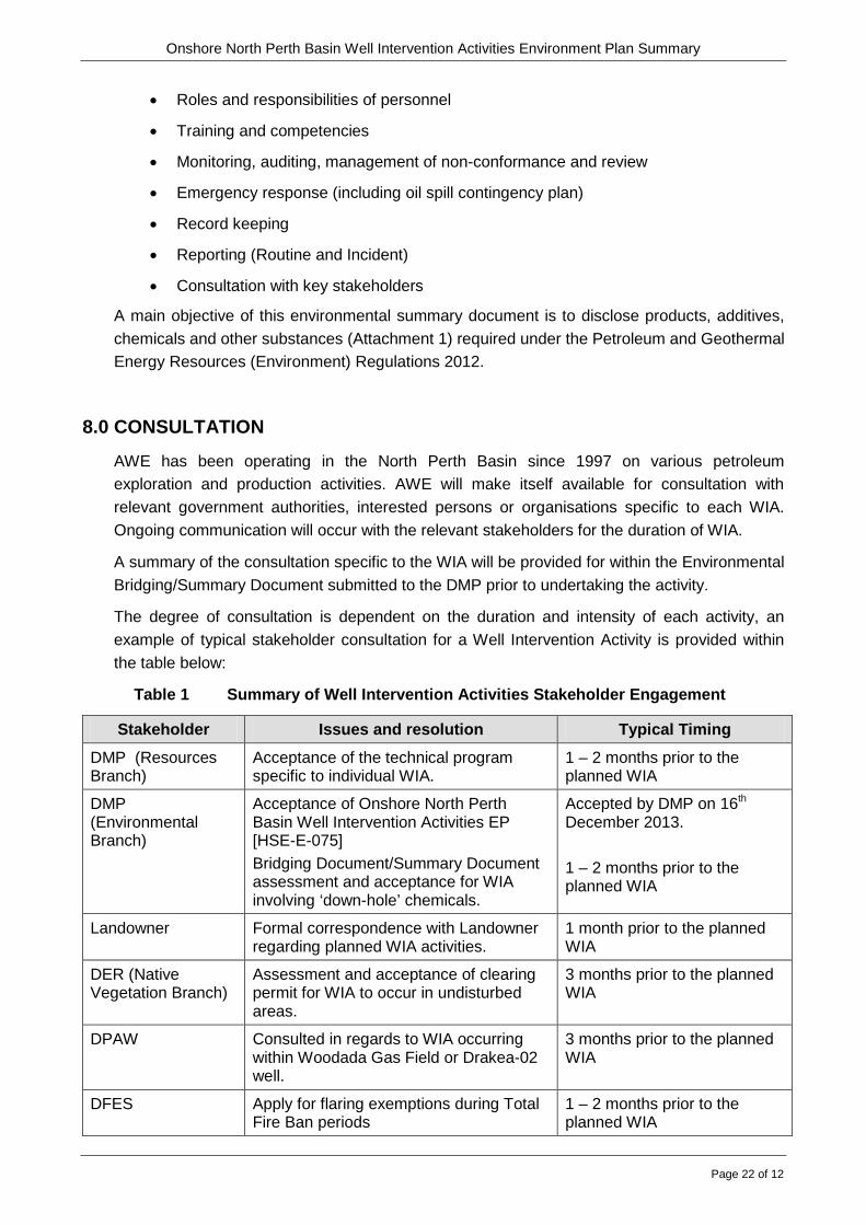
The degree of consultation is dependent on the duration and intensity of each activity, an example of typical stakeholder consultation for a Well Intervention Activity is provided within the table below:
Table 1 Summary of Well Intervention Activities Stakeholder Engagement
Stakeholder Issues and resolution Typical Timing
DMP (Resources Branch)
Acceptance of the technical program specific to individual WIA.
1 – 2 months prior to the planned WIA
DMP (Environmental Branch)
Acceptance of Onshore North Perth Basin Well Intervention Activities EP [HSE-E-075] Bridging Document/Summary Document assessment and acceptance for WIA involving ‘down-hole’ chemicals.
Accepted by DMP on 16th December 2013. 1 – 2 months prior to the planned WIA
Landowner Formal correspondence with Landowner regarding planned WIA activities.
1 month prior to the planned WIA
DER (Native Vegetation Branch)
Assessment and acceptance of clearing permit for WIA to occur in undisturbed areas.
3 months prior to the planned WIA
DPAW Consulted in regards to WIA occurring within Woodada Gas Field or Drakea-02 well.
3 months prior to the planned WIA
DFES Apply for flaring exemptions during Total Fire Ban periods
1 – 2 months prior to the planned WIA

Onshore North Perth Basin Well Intervention Activities Environment Plan Summary
Page 23 of 12
Stakeholder Issues and resolution Typical Timing
DoW Apply for surface aquifer water bore extraction licence and comply with any ongoing monitoring requirements
1 – 2 months prior to the planned WIA
9.0 REPORTING
Reporting under the Petroleum Geothermal Energy Resources (Environment) Regulations 2012 will be undertaken
Quarterly emissions and discharges report (every three months from the approval of an EP and every three months thereafter). DMP have provided a template for the contents of this report.
Annual Environmental Report on all Perth Basin WIA will be submitted for the period 01 July to 30 June documenting:
• Summary of Activities
• Meeting of Objectives and Standards in the EP
• Summary of Audits
• Summary of Incidents
• Planned Emissions and Discharges
• Biological Monitoring/Research
• Identification of New or Increased Risks
• Training and Exercises
• Ongoing Consultation
Monthly Recordable Incident Report on WIAs (by permit) will be submitted on the 15th of the following calendar month for incidents arising from an activity that ‘breaches an environmental performance objective or environmental performance standard in the Environment Plan’ and ‘is not a reportable incident’. A zero report will be submitted where there are no recordable incidents occurred during the month. DMP have provided a template for the contents of this report.
Reportable Incidents are defined in the approved WIA EP. A Reportable Incident will be reported verbally as soon as practicable (within two hours after the occurrence or within two hours of discovery of the occurrence) to 0419 960 621 and [email protected]. The verbal report will be in accordance with Regulation 28(3). It must specify
• All material facts and circumstances concerning the reportable incident that the operator knows or is able, by reasonable search or inquiry, to find out; and
• Any action taken to avoid or mitigate any adverse environmental impacts of the reportable incident).
• A written report must be submitted within three days and must be in accordance with Regulation 29(3). It must specify:

Onshore North Perth Basin Well Intervention Activities Environment Plan Summary
Page 24 of 12
• All material facts and circumstances concerning the reportable incident that the operator knows or is able, by reasonable search or inquiry, to find out and
• Any action taken to avoid or mitigate any adverse environmental impacts of the reportable incident; and
• Any action taken, or proposed to be taken, to prevent a similar reportable incident.
10.0 CONTACT DETAILS
Operations Supervisor AWE Limited Level 4, 679 Murray Street WEST PERTH WA 6005 Phone: 08 9480 1300

Onshore North Perth Basin Well Intervention Activities Environment Plan Summary
Page 25 of 12
ATTACHMENTS

Onshore North Perth Basin Well Intervention Activities Environment Plan Summary
Page 26 of 12
Attachment 1. WIA Generic Chemical Summary
Attachment 2. Material Safety Data Sheets

Attachment 3. WIA Environmental Risk Assessment

RISK IDENTIFICATION
POST TREATMENT RISK
RISK TREATMENT
RISK ANALYSIS RISK EVALUATION
Aspect Impacts Source of Risk Consequence Likelihood Risk Ranking Existing Safeguards / Management Methods
1. Removal of native vegetation and potential habitat
Loss of vegetation
Destruction of fauna habitat
Soil lost through water and wind erosion,
Increased groundwater salinity
Introduction of noxious weeds and vermin, exotic species, flora and animal diseases
Prosecution
Uncontrolled vehicle access
Personnel conducted clearing activity without internal permission in writing or a clearing permit in place
2 3 Medium 5
End of Well Intervention Activity Environmental Report.
Existing access tracks used.
Topsoil to be stock piled and used for rehabilitation (Any clearing that requires regulatory approval will trigger an Environmental Plan Bridging Document submission to the relevant regulatory bodies for approval).
Personnel trained in local environmental sensitivities during RapidInduct induction.
Request for clearing form submitted to Environment Advisor and provide applicant with permission in writing and/or clearing permit.
2. Soil disturbance Increased Erosion and sedimentation
Compaction
Subsidence
Dust
Dust from vehicle and machinery movement
1 4 Medium 5
WIA on existing wellsites
Well sites rehabilitated as soon as practicable after P&A (within two years – as per DMP requirement)
Region is underlain by limestone so there is a low potential for subsidence.
Dust-control measures implemented (e.g. water spraying) if dust generation becomes a problem.
Speed limits are signposted around all sites. On all AWE Operated Production Facilities, there are site specific speed limits signposted at or near the entrance to the Production Facilities.
For remote well sites and their access tracks, site specific speed limits are set at the beginning of WIA with considerations for soil erosion and other factors like moving livestock.
Use of existing roads and tracks only.
3. Disturbance of indigenous heritage site Disturbance of heritage site
Damage/destruction to heritage site Heritage sites not previously determined during ethnographic / archaeological studies (where appropriate)
2 1 Low 3
WIA on existing wellsites
Ethnographic / Archaeological studies carried out by qualified personnel.
Personnel trained in local environmental sensitivities during RapidInduct induction.
WIA located to avoid indigenous cultural areas.
4. Introduction of noxious weeds and vermin, dieback, exotic species, flora and animal diseases to receiving environment
Introduction of exotic species or weeds
Infection of soil with diseases and pathogens
Spread of weeds / dieback into unaffected areas
Exotic species could become invasive if introduced, with unpredictable consequences for native species
Encroachment into quarantine areas
Mobilisation of equipment to site
Vehicles carrying seeds from affected areas
Weeds and contaminated soil on vehicles
Transit through dieback affected areas
2 2 Low 4
WIA on existing wellsites
Designated access tracks used only
Regular vehicle inspections
RapidInduct induction
Equipment cleaned and inspected for soil, plant material and pest animal contamination prior to mobilisation to minimise risk of introducing exotic species with advice from CALM.
Personnel trained in quarantine procedures where required
Exotic species monitored during auditing and inspection program.
NOTE:
This is only required in specific areas such as: Woodada Gas Field WIA or other environmentally sensitive areas such as nature reserves.
Implement 60km/hr. speed limit on access track.

RISK IDENTIFICATION
POST TREATMENT RISK
RISK TREATMENT
RISK ANALYSIS RISK EVALUATION
Aspect Impacts Source of Risk Consequence Likelihood Risk Ranking Existing Safeguards / Management Methods
5. Impact of noise on local residents, wildlife or adjacent activities
Disturbance to local residents, wildlife or adjacent activities
Noise levels above occupational health levels
Disruption of sensitive fauna habitats
Noise generated during routine WIA
Noise and/or vibration generated during routine operations
1 2 Low 3
WIA on existing wellsites
General area has low population density and is remote from high density populations e.g. Dongara.
Ear protection for workforce
Avoidance of sensitive fauna habitats
Noisy activities scheduled for daylight hours
Noise monitoring equipment where near noise sensitive premises
6. Fuel, oil or chemical spills
Contamination of soil, surface water or groundwater
Lack of appropriate bunding around storage and handling areas
Inappropriate storage of fuel, oil or chemical containers
Inappropriate handling of fuel, oil or chemicals during use
Spill during handling
Leak
Spillage
Failure of diesel tank 3 1 Low 4
Equipment and chemicals oriented within bunded areas to ensure no impact on water bodies
Flammable and corrosive materials are segregated within the wellsite chemical storage area.
Containers checked to ensure that they are in sound order.
Personnel trained in the correct procedures for use of materials, including clean-up procedures.
Emergency response plan and Oil Spill Contingency Plan in place and personnel trained in their implementation.
Clean-up materials available in all relevant areas.
Clean-up materials and wastes appropriately contained for offsite disposal.
RapidInduct induction
Use of MSDSs.
MSDSs located in site office and chemical storage shed.
Keeping chemicals offsite until necessary.
7. Gas release Crude Oil / Condensate release
Localised contamination of site by hydrocarbons
Contamination of groundwater
Gas emissions to atmosphere
Instrument gas venting
Breathing at vent on storage tanks
PSV lifting
Overpressure of line
Pipeline leak / failure
Water level failure at separator
Failure or leakage of equipment
Blowout
Equipment failure
Loss of combustion during flaring
3 2 Medium 5
Operate equipment to specifications and standard procedures
Pressure test
Weekly BOP stack testing
RapidInduct induction
Routine maintenance and inspections
OSCP and ERP in place
Clean-up all spills
Blow out preventor (if required) in use and regularly tested.
Generally wells to be worked over are depleted
Appropriate measures in place to prevent loss of combustion during flaring.
Crude oil and separator tank bunded
8. Gas flaring Greenhouse gas emission
Landowner Complaints
Prosecution
Black smoke
WIA flaring in restricted burning period with no permit
Failure to advise landholder of black smoke during WIA flaring 1 1 Low 2
Minimise volume of gas to be flared where possible.
Obtain approval from DMP (and DFES during restricted burning period) for flaring.
Use of Ringelmann to classify dark smoke emissions

RISK IDENTIFICATION
POST TREATMENT RISK
RISK TREATMENT
RISK ANALYSIS RISK EVALUATION
Aspect Impacts Source of Risk Consequence Likelihood Risk Ranking Existing Safeguards / Management Methods
9. Fire Release of noxious gases
Bushfire – loss of vegetation, fauna and/or habitat
Disruption of operations and site access
Damage to equipment
Damage to site offices
Loss of crops
Destruction of fauna habitat
Site not maintained clear of vegetation
Ignition sources e.g. vehicle exhaust, smokers
Hot work
Flaring of gaseous waste
Lightning strike
Ignited gas release
Vehicle incident
Arson
Offsite uncontrolled bushfire
3 3 Medium 6
Adequate fire equipment located on-site and personnel trained in its use.
Smoking allowed at designated smoking location only.
All vehicles fitted with a fire extinguisher
Diesel vehicles only on site
Exemption under the Bushfires Act 1954 for restricted burning operations
ERP
RapidInduct induction
Local emergency response - fire brigade and DFES
Permit to Work System
Equipment classified for hazardous areas
10. Vehicle related incident
Breaching of wellhead / pipe rupture
Gas release
Diesel / hydrocarbon spill
Fauna death
Vehicle collision with infrastructure
Vehicle rollover / Impact
Vehicle impact with fauna
2 3 Medium 5
RapidInduct induction
OSCP in place
Speed limits in place
Designated car park for WIA Site
Daily inspections of machinery onsite
Weekly vehicle inspections
Maintenance of access tracks
11.Disposal of wastes:
Industrial and domestic wastes produced may contaminate the receiving environment
Release of waste oils or chemicals into the environment
Loss of rubbish into the environment
Environmental damage due to spill of waste product
Litter left around the wellsites
Hydraulic Fracture Stimulation fluid discharged into the environment
Soil, surface water and groundwater contamination
Mortality of flora and fauna arising from soil, surface and groundwater contamination
Visual pollution from rubbish
Potential contamination of soils and aquifers
Visual pollution from rubbish
Improper disposal of wastes
Waste not disposed of according to Solid Waste to Landfill Guidelines
Waste skips not covered
Site wastes and chemicals not removed at end of program
HFS fluid discharged into the environment
Sewage / grey water leaching into water table
1 4 Medium 5
Maintenance of mandatory waste records including type and volumes.
RapidInduct induction
Segregation of Wastes
Use of local waste management contractor.
Solid wastes such as scrap wood, metal, packaging and litter segregated and stored in skip bins for offsite recycling or disposal by waste management contractor.
Waste chemicals labelled and stored appropriately for offsite disposal by waste management contractor
Industrial and solid wastes transported to Meru or other appropriate waste management facility
All bins (where appropriate) covered to prevent rubbish entering the environment
WIA generate a minimum volume of waste.
Water-based KCl kill fluids and wastewater (eg. HFS fluid) disposed of to the HPF or to claylined flare or other lined pit. Dried solid retention pond material sampled and disposed of to an appropriate landfill in accordance with the Solid Waste to Landfill Guidelines.
Short duration of WIA
Portable toilets used
Site inspected at conclusion of WIA.
End of WIA and Annual Environmental report

RISK IDENTIFICATION
POST TREATMENT RISK
RISK TREATMENT
RISK ANALYSIS RISK EVALUATION
Aspect Impacts Source of Risk Consequence Likelihood Risk Ranking Existing Safeguards / Management Methods
12.Groundwater contamination
Groundwater contamination HFS Activities fluids permeate outside target zone
Unidentified fault allowing fluid migration vertically
Retention pond or flare pit impermeable barrier failure
4 1 Medium 5
Confining layers (due to depth of wells)
Fractures tend to spread laterally rather than vertically due to rock formation discontinuities
Cement sheathed casings prevent the propagation of fluids into upper sections of wells
Low concentration of chemicals in HFS fluids
Flare pit and water retention pond will be lined to ensure that the superficial aquifer is protected from produced hydraulic fracturing water.
Monitoring of annuli pressures at surface during treatment (operations suspended when pressures outside of expected range)
13.Wellhead works leak / failure
Contaminated soil
Contaminated groundwater
Oil spill
Ignition of release – resulting in fire
Flange failure due to heat deformation/ structural fatigue/ seismic activity
Impact from vehicle
Unauthorised earthworks
Corrosion 4 2 Medium 6
Planned inspections and maintenance of wellhead works.
Equipment operated to specifications and standards.
WIA prestart inspection process followed.
Trained and certified personnel.
Policy that all reversing heavy vehicles and machinery on site must have spotters
Dedicated parking area
14.Failure to comply with Environmental Reporting Requirements
Failure to meet Environmental Licence commitments
Prosecution Compliance Schedule (containing report deadlines) is ignored
WIA Personnel not briefed on Environmental Licence Requirements
1 2 Low 3
End of WIA Environmental Report submission to Environmental Advisor following every WIA
Site specific induction contains explanation of Environmental Licence Requirements
Annual Environmental Report for each field due 31st July each year
National Pollutant Inventory reporting due 30th September each year
National Greenhouse and Energy Report due 31st October
Annual check of fuel combusted (for all facilities) against Energy Efficiency Opportunities Act threshold to determine if required to participate in the program
Bridging document where chemical disclosure is required.
Environmental Incident Control
Monthly recordable incidents
Quarterly emissions and discharges reports
