permanent magnet dc traction motor with...
TRANSCRIPT
i
High-Speed Rail IDEA Program
Permanent Magnet DC Traction Motor With Reconfigurable Winding Control Final Report for High-Speed Rail IDEA Project 44 Prepared by: Nicholas N. Rivera, PE SPAD Engineering Company August 2007

ii
INNOVATIONS DESERVING EXPLORATORY ANALYSIS (IDEA) PROGRAMS MANAGED BY THE TRANSPORTATION RESEARCH BOARD This investigation was performed as part of the High-Speed Rail IDEA program supports innovative methods and technology in support of the Federal Railroad Administration’s (FRA) next-generation high-speed rail technology development program. The High-Speed Rail IDEA program is one of four IDEA programs managed by TRB. The other IDEA programs are listed below. • NCHRP Highway IDEA focuses on advances in the design, construction, safety, and maintenance
of highway systems, is part of the National Cooperative Highway Research Program. • Transit IDEA focuses on development and testing of innovative concepts and methods for
improving transit practice. The Transit IDEA Program is part of the Transit Cooperative Research Program, a cooperative effort of the Federal Transit Administration (FTA), the Transportation Research Board (TRB) and the Transit Development Corporation, a nonprofit educational and research organization of the American Public Transportation Association. The program is funded by the FTA and is managed by TRB.
• Safety IDEA focuses on innovative approaches to improving motor carrier, railroad, and highway safety. The program is supported by the Federal Motor Carrier Safety Administration and the FRA.
Management of the four IDEA programs is integrated to promote the development and testing of nontraditional and innovative concepts, methods, and technologies for surface transportation. For information on the IDEA programs, contact the IDEA programs office by telephone (202-334-3310); by fax (202-334-3471); or on the Internet at http://www.trb.org/idea IDEA Programs Transportation Research Board 500 Fifth Street, NW Washington, DC 20001 The project that is the subject of this contractor-authored report was a part of the Innovations Deserving Exploratory Analysis (IDEA) Programs, which are managed by the Transportation Research Board (TRB) with the approval of the Governing Board of the National Research Council. The members of the oversight committee that monitored the project and reviewed the report were chosen for their special competencies and with regard for appropriate balance. The views expressed in this report are those of the contractor who conducted the investigation documented in this report and do not necessarily reflect those of the Transportation Research Board, the National Research Council, or the sponsors of the IDEA Programs. This document has not been edited by TRB. The Transportation Research Board of the National Academies, the National Research Council, and the organizations that sponsor the IDEA Programs do not endorse products or manufacturers. Trade or manufacturers' names appear herein solely because they are considered essential to the object of the investigation.

iii
Permanent Magnet DC Traction Motor With Reconfigurable Winding Control
IDEA Program Final Report
For the Period June, 2003 through September, 2006 Contract Number HSR-44
Prepared for The IDEA Program
Transportation Research Board National Research Council
Nicholas N. Rivera, PE SPAD Engineering Company
August, 2007

i
ABSTRACT
This project is to design, build and test a prototype locomotive traction motor based on a new electric machine technology defined as a “permanent magnet direct current machine with reconfigurable winding control”. The most significant innovations in this technology are the topologies of magnetic circuits and windings and the solid state switching and control system that replaces either the commutator and brushes or an external power converter. This electric machine has high energy permanent magnets that produce an intense and uniformly distributed air gap field and windings made of coils concentrated in slots. A power electronic control system reconfigures sets of those stator windings from series to parallel combinations to reduce the rate at which back-emf increases with speed. That precludes the need for rising drive voltages as required by existing traction control systems to overcome increased back-emf produced by rising speed. The air gap field and winding configuration and control feature combined with the power electronic control system, this combination called the “slot path” concept, results in optimum utilization of motor space and materials for best torque-speed performance. This is advantageous to traction motors directly mounted on wheel axles with significant weight reduction combined with resultant high adhesion over a much wider speed range. The product provides for fine torque/speed control resolution at a low speed down to 1 mph and up to speeds in excess of 100 mph. Prototype core components of a traction motor were designed and built for installation in the casing of a General Motors D77 traction motor from a GP-38 locomotive to test and evaluate the technology capabilities. The core components of the prototype are approximately 1/4 of the weight and volume of those of the original GM D77 motor. Successful test results of a much larger motor developed for the U.S. Navy that employs the same general concept are a prerequisite for completion and testing of the traction motor. Functional tests of the Navy motor showed failures of power control modules when exposed to energy discharged from its large winding inductances. Commercially available power control modules used under the application criteria for which they were originally developed proved inadequate for use in the slot path concept architecture. Several options to resolve this application conflict have been determined and actions are underway to incorporate and test a workable option.
KEY WORDS electric traction electronic commutation permanent magnet motor rail traction traction drive traction motor unsprung mass
ii
TABLE OF CONTENTS Page Abstract and Key Words i List of Figures iii Executive Summary 1 Introduction 3 Background and Objective 3 IDEA Product 4 Concept and Innovation 9 Investigation 9 Project Panel 17 Conclusions 17 Plans for Implementation 18 References 18

iii
. LIST OF FIGURES Page 1. Combined Motor Performance Curves 6 2. New Motor Installation in GM D77 Housing 7 2A. Old GM D77 Motor in Housing 8 3. Generic Machine with One Slot Path Circuit Highlighted 13 4. Schematic Slot Path Circuit for Traction Motor 14
1
EXECUTIVE SUMMARY This project is to design, build and test a prototype locomotive traction motor based on a new electric machine technology defined as a “Permanent Magnet Direct Current Machine With Integral Reconfigurable Winding Control”. The most significant innovations in this technology are the topologies of magnetic circuits and windings and the solid state switching and control system that replaces either the commutator and brushes or an external power converter. This electric machine concept is optimized to utilize its volume and material characteristics to produce high torque and power density combined with very high efficiency. Physical and electromagnetic structures that use high energy permanent magnet assemblies, winding configurations and an electronic commutation control system provide for optimum utilization of magnetic circuits to produce torque and power with a significantly extended speed range. The specific air gap field distribution and winding configuration and control feature integral with the electronic commutation control system is defined as the “slot path” concept. The coils in a slot path circuit are concentrated in narrow radial slots in the stator and are arranged to couple different consecutive poles. The slot path control system reconfigures those sets of stator coils from series to parallel combinations to reduce the rate at which back-emf increases with speed. That precludes the need for rising drive voltages as required by existing traction control systems to overcome increased back-emf produced by rising speed. A result is optimum utilization of motor space and materials for best torque-speed performance. This is especially advantageous to a traction motor mounted on a wheel axle as an “unsprung mass”, such mass reduced to less than 1/2 of the original and combined with higher adhesion over a much wider speed range. When industrial production status of the slot path concept technology is reached, there are no associated components or processes which would cause either its acquisition or its operational costs to be significantly higher than today's conventional traction technologies. Indeed, some reductions in comparative total life cycle costs may be achievable. Engineering developments include the use of lumped parameter design calculations supplemented by mechanically coupled FEA electromagnetic and thermal modeling, power electronics and analog/digital control electronics design and computer simulations. A number of slot path circuits are used to provide fine control resolution combined with practically unrestricted torque control at a low speed down to 1 mph and at speeds in excess of 100 mph. All motion control will be smooth and transparent to the human operator with the exception of limited status indication by an LED array. Based on the results of these initial tasks, the expert panel for this project recommended that a full-scale prototype motor be built and tested. Prototype core components of a traction motor were designed and built for installation in the housing of an existing General Motors model D77 traction motor to test and evaluate the technology capabilities as a means of comparison with at least one existing type of traction drive. The core components of the prototype are approximately 1/4 of the weight and volume of those of the original GM D77 motor. The motor controller will be integral with the motor and installed inside of the motor housing. The new motor cores, including the integrated controller, will fit in the existing housing with space to spare. That is, the integrated controller also precludes the need for an external power converter or a motor controller. Successful test results of a much larger motor developed for the U.S. Navy (1200 hp vs. 500 hp) that employs the same general concept are a prerequisite for completion and testing of the traction motor. All functional features of the motor control system were successfully tested on a small proof motor previously developed to serve as preliminary test platform for the Navy motor development project. Functional tests of the Navy motor showed failures of power control modules when exposed to stored energy discharged from its larger winding inductances. Commercially available power control modules used under the application criteria for which they were originally developed proved inadequate for use in the slot path concept architecture. Several options to resolve this application conflict have been determined and actions are underway to incorporate and test the most workable option. Once the necessary modifications to the power controller have been evaluated, testing of the Navy motor will be completed, which will support completion of construction and testing of the traction motor.
2
FINAL REPORT 1. Introduction 1.1 Existing electric motor technologies applied to rail traction consist of commutator-type direct current (DC) and inverter-driven alternating current (AC), induction or synchronous. Those technologies have been sufficiently effective to support revenue service in world rail systems. However, improvements are needed to expand traction capabilities for freight as well as high speed passenger service. Improvements in capacity of adhesion and in wider slow to high speed ranges will enhance revenue service and economy of operation. As an example, existing traction drives cannot support continuous slow speed operation much below 10 mph for such operations as operating high-tonnage trains up long, steep grades. To move as slow as 2 mph, a locomotive with inverter driven, vector controlled AC induction traction drives must repeatedly and sequentially plug the motor in combination with pneumatic braking. This type operation is very stressful and accelerates wear of motors and brakes with adverse impact on service life. Commutator-type DC and synchronous AC typically do not support such slow speed operation. At high speed the torque/speed limitation of AC as well as DC lies in the need to increase voltage to overcome the effects of back-emf. In AC, the solid-state switches used by the inverter drives have absolute maximum voltage ratings. If these absolute ratings are exceeded by either steady-state or transient voltages, the devices are destroyed. This is a typical failure mode of those drives. The maximum driving voltage must then be limited and so is the torque capacity of the traction motor at high speed. Also, more space must be dedicated to insulation instead of copper for motor windings that must be driven at several thousand volts. This makes for larger slots in the stator core and longer magnetic flux lines resulting in increased losses and larger physical size and weight. 1.2 The objective of this High-Speed Rail IDEA project is to introduce to rail traction motor application a new electric machine technology defined as a “permanent magnet direct current machine with reconfigurable winding control”. This electric machine concept is optimized to utilize its volume and material characteristics to produce high torque and power density combined with very high efficiency. Physical and electromagnetic structures that use powerful permanent magnet assemblies and an electronic commutation and winding configuration control system provide for optimum utilization of magnetic circuits to produce torque and power with a significantly extended speed range. The control system reconfigures sets of stator windings from series to parallel combinations to reduce the rate at which back-emf increases with speed. This precludes the need for rising drive voltages as required by existing traction control systems to overcome increased back-emf produced by rising speed. A result is optimum utilization of motor space and materials for best torque-speed performance. This is advantageous to traction motors directly mounted on wheel axles with significant weight reduction combined with resultant high adhesion over a much wider speed range. The product provides for continuous torque/speed control resolution at a low speed down to 1 mph and at higher speeds in excess of 100 mph. 2. Background and Objective 2.1 Comparative Traction Technologies and Significance to Rail Performance References [a] and [b] provide comprehensive descriptions and analyses of existing traction technologies. Reference [a] has a tabulation of existing drive systems with some quality grading information and Reference [b] describes and evaluates existing direct current (DC) and alternating current (AC) traction systems. The latest existing traction drive technologies consist of three phase, AC induction or synchronous motors driven by variable frequency, variable voltage inverters. Those motor concepts switch entire phase or pole windings to convert power to a usable mechanical form. A parasitic effect of switching entire phase or pole windings in AC motors is the induction of substantial heat in their rotors that forces designers to oversize them to provide for heat dissipation. To reduce that rotor heating effect, power conditioners and/or variable pulse width modulation (PWM) architectures are used to make the shape of inverter outputs closer to sine waves. This limits the utilization of magnetic core circuits in the motors to approximately 36 percent. The torque/speed

3
limitation of present AC lies in the need to increase voltage to overcome the effects of back-emf. The solid-state switches used by the inverter drives have absolute maximum voltage ratings. If these absolute ratings are exceeded by either steady-state or transient voltages, the devices are destroyed. This is a typical failure mode of those drives. The maximum driving voltage must then be limited and so is the torque/speed capacity of the traction motor. Inverter driven synchronous motors are used for high speed passenger service because their air gap fields can be somewhat reduced for higher speed operation. With reduced air gap field a synchronous motor generates less back-emf to enable it to reach a higher speed without need for excessively high driving voltage, but its torque capacity is also reduced. Synchronous motors are larger and heavier, and thus not good for direct mounting on wheel axles. Those motors are suitable for the lesser adhesion and high speed required by passenger service, not for freight service. Reference [c] provides performance assessments of AC locomotives. This reference provides many points on performance analysis and comparisons of those drives as follows: Χ The maximum attainable factor of adhesion by AC traction motors is 35 to 45 percent while DC
motors are limited to 30 percent for a given horsepower rating. Therefore, a 4000 HP AC locomotive has the same tractive effort capacity as a 5000 HP DC locomotive.
Χ AC (induction) motors driven by inverters with vector control can produce the torques needed for high
adhesion, especially at startup and low speed. Χ Tractive effort vs. horsepower - Torque capacity drives the size and weight of a motor. AC motors
have higher torque capacity at low speeds but are limited at high speed, so their high speed horsepower capacity is limited. Less horsepower means lower maximum speed and longer running times.
Χ DC motors have less torque capacity at low speed, but their high speed torque capacity sustains a
higher horsepower capacity. Trains driven by DC motors can reach track speed more quickly. Χ The weight of traction motors that are mounted on the wheel axles is limited by the impact load
sustainable by wheel and rail. Thus, the torque and power capacity is limited by weight. Χ Simulations done on the Train Energy Model (TEM) developed by the Association of American
Railroads show that the tractive effort/horsepower relationship of present AC transmissions result in significantly longer running times than with DC transmissions. On a busy mainline carrying mixed traffic, the performance of AC units may cause dispatch problems. Average length of haul distance is well over 750 miles.
Χ Electric transmission should allow for maximum horsepower output at any speed depending on the
torque/speed characteristic of the drive motors. Present electric motors have decrementing torque/speed characteristics and relatively low torque and power densities at any speed, including startup. If the torque/speed decrement is too pronounced, the motors may not be able to utilize the full capacity of the prime mover.
Χ Two kinds of adhesion factors: starting adhesion and continuous or dispatchable (running) adhesion.
Adhesion factors depend on wheel slip control to reach maximum achievable adhesion at any speed. That is, all wheels pull in unison if none slip. This is one reason why AC transmissions have better adhesion than DC. The performance of DC motors can not be matched and controlled as tightly as inverter-driven AC.
Χ For heavy trains operating on grades of 1% or more, distributed motive power must be used.
4
Χ The effect of grade is linear, therefore the train weight that a locomotive combination can operate is
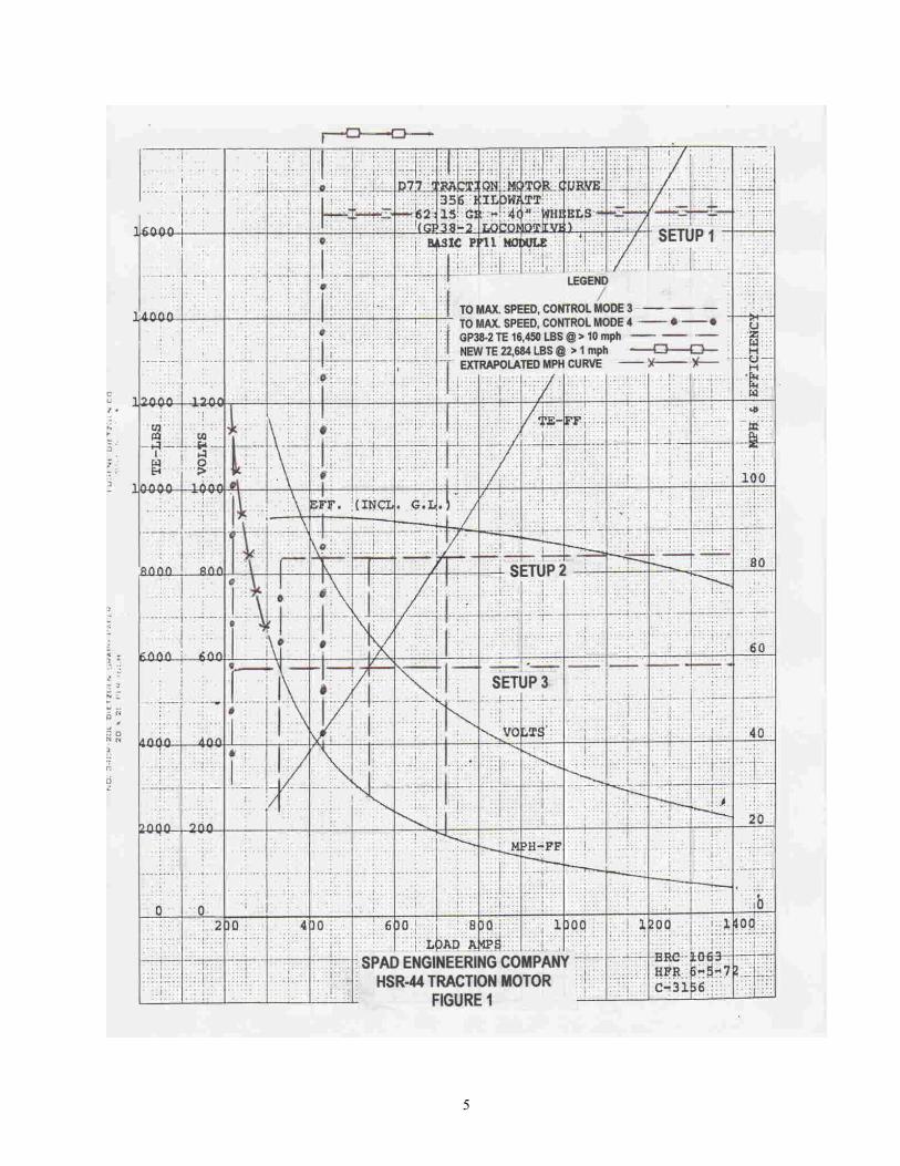
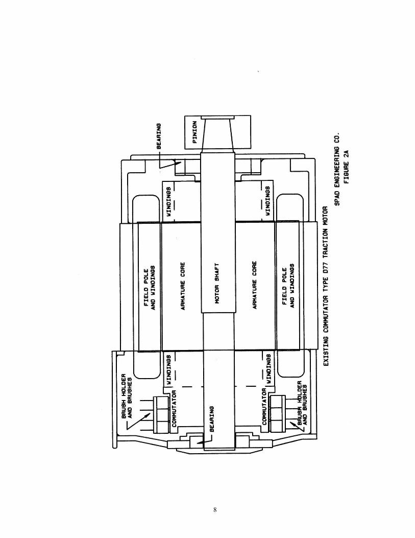
inversely proportional to the grade. Χ Market for very high horsepower locomotives is on the rise in the U.S. and Canada. 2.2 Objective The objective of this project is to design, build and test a locomotive traction motor based on a new electric machine technology to provide a means of evaluation as applied to rail traction. 3. IDEA Product The IDEA product consists of a prototype traction motor designed and built for test and evaluation. 3.1 Configuration of the Prototype The traction motor prototype will be installed in the housing of a General Motors model D77 (GM D77) traction motor used on a GP38-2 locomotive. The design uses the performance characteristics of the GM D77 motor for a GP38-2 locomotive as a means of comparison. The prototype components to be installed in the GM D77 housing include the PM rotor, stator with heat exchanger and power electronic controller. This installation will also use the original GM D77 shaft, pinion (62:15 GR) and bearings and will conform to the original GM D77 geometry, a critical factor being the distance between the axis of the wheel axle and the axis of the motor shaft. This will provide for direct installation of the motor in a GP38 locomotive for future industrial validation testing. The designed performance parameters of this motor exceed the GM D77 characteristics shown in the GM D77 traction motor curve ERC 1063, HFR 6-5-72, C- 3156 shown in Figure 1. Design constraints are imposed by the geometry of the GM D77 motor housing internal dimensions and by the critical distance between the axis of the wheel axle and the axis of the motor shaft. The prototype motor cores are axially much smaller than those of the GM D77 motor such that the housing could be made shorter. The positions of the wheel axle bearings attached to the housing preclude reduction of axial length, however the prototype motor cores are about 1/4 of the weight of those of the GM D77 motor. That is, given that the GM D77 motor housing is about 2200 lbs. and its total weight is 6300 lbs., the completed prototype motor will have a weight of about 3300 lbs. Figure 2 shows a scaled profile of the new motor components installed in the GM D77 motor housing and Figure 2A shows the same view of the original GM D77 motor as a means of comparison.
5

6
3.3 Motor Performance Specifications The prototype motor is designed for a performance envelope that will encompass the TE vs. MPH-FF (speed) characteristics of the GM D77 traction motor for a GP38-2 locomotive shown in Figure 1. The torque-speed capacity of the new motor technology is inherently flat, so that torque capacity does not droop with speed. Thus, the prototype design provides for a characteristic consisting of three blocks, each with a substantially constant torque or TE capacity for a different speed range. These are to be controlled seamlessly by three control “setups.” Figure 1 shows the TE vs. speed characteristics under the three setup control features. Note that within each control setup, TE and speed will also be adjustable with high resolution to suit actual demand without incurring wheel slip. TE and torque capacities vs. speed are: Continuous TE - lbs./ Max. Torque - ft-lbs. Speed - mph Setup 1 16450 / 22684 6633 / 9147 1 to 18.8 / 38.1 Setup 2 8400 3397 1 to 28.2 / 56.9 Setup 3 5800 2339 1 to 56.9 /113.9 3.4 Comparison with Performance of Original GM D77 Motor Performance characteristics of the GM D77 motor are shown in curve ERC 1063, HFR 6-5-72, C- 3156 for a GP 38-2 Locomotive shown in Figure 1. These motor curves with supplemental information show that the GM D77 motor could not operate continuously at high TE load below a speed of about 10 mph. Operation below that speed would be thermally limited. The TE vs. MPH-FF vs. VOLTS characteristics in the GM D77 motor curves show an increasing driving voltage in excess of 600 VDC required to meet the TE load at high speed. That is, to reach higher speeds under the TE load profile, the GM D77 motor will require a driving voltage above the 600 VDC capacity limit of the GP38-2 locomotive. In contrast the prototype motor design exceeds the load capacities and the maximum speed range shown in the curves while driven by a non-changing 600VDC source. The prototype motor performance envelope described and tabulated in 3.3 above exceeds the original TE vs. speed characteristics while driven at a maximum voltage of 600 VDC. That is, the prototype motor design as evaluated by FEA simulations will be capable of reaching a TE of 22,684 lbs at a slow speed down to 1 mph and a high speed of 113.9 mph with TE of 5800 lbs. This performance betters the original characteristics by large margins. 3.5 Potential Impact on Transportation Practice Further developments of this technology will achieve direct drive traction motors with extremely high torque capacities and low weights and volumes. Also, motors like the prototype of this project may be back-fitted in existing DC locomotives to significantly improve performance and service life. Potential impacts or payoffs for practice are many. For example, this will overcome limitations of existing technologies in the following areas as shown in the literature: X In North American locomotives, traction motors are primarily supported directly on the wheel axles,
therefore their “unsprung mass” must be limited by the impact load sustainable by wheel and rail. Thus the torque and power capacity of existing technology traction motors is limited by weight. [c]
Χ Present electric traction motors have decrementing torque/speed characteristics and limited torque and power densities at any speed, including startup. [c]
Χ Present traction motors cannot support continuous low speed operation under maximum tractive effort.

7
8

9
4. Concept and Innovation The new technology is defined as a “permanent magnet direct current motor with reconfigurable winding control”. This motor concept uses an innovative approach to deal with back electromotive force (back-emf). It has an electronic commutator arrangement that reconfigures the windings from series to parallel combinations to reduce the rate at which back-emf increases with speed. That precludes the need for rising drive voltages as required in existing traction control systems to overcome increased back-emf produced by rising speed. The electronic commutation controller is physically integrated with the machine in the same housing. Windings are reconfigured by changing the number of coils connected in series between the positive and negative terminals of the power source. That is, considering the back-emf of each coil, the resultant back-emf is lower for fewer coils connected in series at any speed. In a motor this allows for flow of enough winding current to maintain high torque capacity at higher speeds. Then the voltage delivered to the motor windings may be constant and selectable at the most convenient value to support the required performance. The specific winding configuration control feature integral with the electronic commutation control system is defined as the “slot path” concept. The coils in a slot path circuit are concentrated in narrow radial slots in the stator and are arranged to couple different consecutive poles. The motor has different modes of operation by reconfiguring the connections of the coils of one or more slot path circuits from series relationships to parallel relationships or to hybrid series-parallel relationships. The rotor has high-energy permanent magnets that produce an intense and uniformly distributed air gap flux density. At any given point in time, the flux of each magnet pole passes through all concentrated coils of a slot path circuit covered by the pole, except at the point of transition between poles, which is a short-duration event. That is, the coils of each slot path circuit are almost continuously under a high air gap field of non-changing magnitude, excepting the brief transitions between poles. Only one slot path circuit per pole is switched at a time to commutate polarities. This makes soft switching (under zero null current) possible and reduces switching energy to a small fraction of what would exist if a distributed winding coupling the entire pole is commutated. Core losses are also reduced by the small field coupling presented by switching one concentrated winding out of many. Thus, this concept has lower core losses and electric conduction losses than prior technology machines. With uniformly distributed air gap flux and winding currents, maximum energy is stored in the air gap and utilized to better than 90 percent compared to the 36 percent limit of other technologies that must use inverters with sine wave outputs. The result is optimized utilization of motor space and materials for maximum torque and power density. When industrial production status of the slot path concept technology is reached, there are no associated components or processes which would cause either its acquisition or its operational costs to be significantly higher than today's conventional traction technologies. Indeed, some reductions in comparative total life cycle costs may be achievable. This is advantageous to traction motors directly mounted on wheel axles (unsprung mass) with significant weight reduction combined with resultant high adhesion over a much wider speed range. The product provides for fine torque/speed control resolution at a low speed down to 1 mph and at high speeds exceeding 100 mph. Prototype core components of a traction motor were designed and built for installation in the casing of a GM D77 traction motor to test and evaluate the technology capabilities as a means of comparison with at least one existing type of traction drive. The core components of the prototype are approximately 1/4 of the weight and volume of those of the original GM D77 motor. The motor controller will be integral with the motor and installed inside of its casing. 5. Investigation 5.1 Design, development and shop tests were done by the following methods. • The housing and shaft components for a GM D77 traction motor were provided to the project by the
Norfolk Southern Corporation shops in Altoona, PA.
NAS Contract HSR-44
10
• Traction motor performance specifications were derived from the GM D77 traction motor curve ERC
1063, HFR 6-5-72, C- 3156 for a GP 38-2 Locomotive (Figure 1). These were supplemented by information on the GP38-2 locomotive such as generated voltage capacity and minimum sustainable speed at maximum tractive effort (TE).
• Tradeoff analyses were done to select initial dimensions, materials and winding configurations to
support the specified performance of the machine to be fitted under the geometrical constraints of the GM D77 housing. This defined the number of slot path circuits and basic slot path circuit control scheme to be integrated in the motor.
• Lumped parameter design calculations were done for the prototype machine followed by extensive
computer simulations to complete and evaluate the detailed design. The simulations involved mechanically coupled electromagnetic and thermal modeling using customized finite element analysis (FEA) methods and software. The machine models including geometry, material characteristics, windings and the slot path circuits were accurately built in the computer. Several sets of models were produced to simulate the above described coil setups. Computer simulations were done for each of the models under dynamic conditions for each setup and control mode condition. The objective of the simulations was to very accurately sample performance and compare to that described above for the lumped parameter design calculations.
Results of the dynamic test simulations compared very favorably with results of the lumped parameter calculations. High load causes an “armature reaction” that tends to reduce and distort the magnetic intensity distribution of the air gap. These simulations showed relatively low distortion as compared to the static condition. The worst case within acceptable limits was for the maximum load under a TE of 22684 lbs. This is also verified by finding that the variances of currents in every slot are within 4 percent in every case. This is as expected by the operational principles of the slot path concept. The simulation calculations yielded a lot of additional information not included here to avoid a burdensome presentation. Answers to more detailed questions can still be extracted interactively.
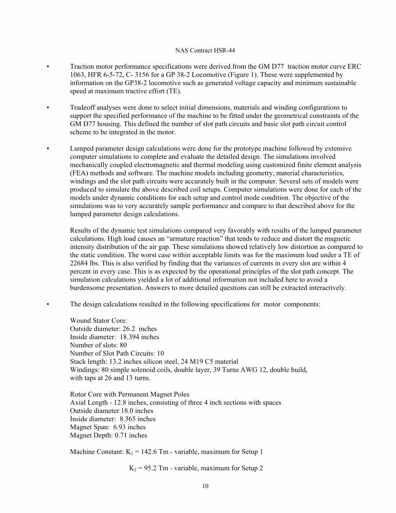
• The design calculations resulted in the following specifications for motor components:
Wound Stator Core: Outside diameter: 26.2 inches Inside diameter: 18.394 inches Number of slots: 80
Number of Slot Path Circuits: 10 Stack length: 13.2 inches silicon steel, 24 M19 C5 material Windings: 80 simple solenoid coils, double layer, 39 Turns AWG 12, double build,
with taps at 26 and 13 turns.
Rotor Core with Permanent Magnet Poles Axial Length - 12.8 inches, consisting of three 4 inch sections with spaces Outside diameter:18.0 inches
Inside diameter: 8.365 inches Magnet Span: 6.93 inches Magnet Depth: 0.71 inches
Machine Constant: K1 = 142.6 Tm - variable, maximum for Setup 1 K2 = 95.2 Tm - variable, maximum for Setup 2

11
K3 = 47.2 Tm - variable, maximum for Setup 3
Coil Currents: 23.5 amp - maximum in Setup 1, Control Mode 1 at a TE of 16,450 lbs 32.4 amp - maximum in Setup 1, Control Mode 1 at a TE of 22,684 lbs
Losses: 15.5 Kw - maximum in Setup 1, Control Mode 1 at a TE of 16,450 lbs 29.5 Kw - maximum in Setup 1, Control Mode 1 at a TE of 22,684 lbs 6.0 Kw - maximum in Setup 2, Control Mode 4 at a TE of 8,400 lbs
5.8 Kw - maximum in Setup 3, Control Mode 4 at a TE of 5,800 lbs • Based on the design calculation and simulation results that provided heat loss and temperature rise
data a heat exchanger was designed. For a medium speed motor, copper losses amount to more than 95 percent of the total. The heat exchanger will be made of copper tubing thermally bonded to the end turns of the motor windings where most of the heat losses are generated. The cooling fluid will be free flowing tap water at ambient pressure. The heat exchanger will comfortably maintain temperature rise within 80o C with a TE load of 16,450 lbs but may require increased flow and/or pressure under the much higher TE load of 22,684 lbs.
• To meet the project schedule advance procurement of the core components including
stator, rotor with magnet assemblies and housing of the prototype motor was done. This included adaptive modifications of the GM D77 motor housing provided by Norfolk Southern Corporation.
• Performance specifications were drafted for a controller to be integrated with the motor to
support the performance requirements of the traction motor prototype. The controller must use commercially available solid state power control modules as prescribed in the application criteria provided by manufacturers. The performance of basic developments in the area of solid state power electronics should be beyond the scope of projects such as this one. This approach resulted in problems to be discussed in the bottom section below.
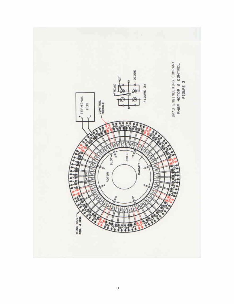
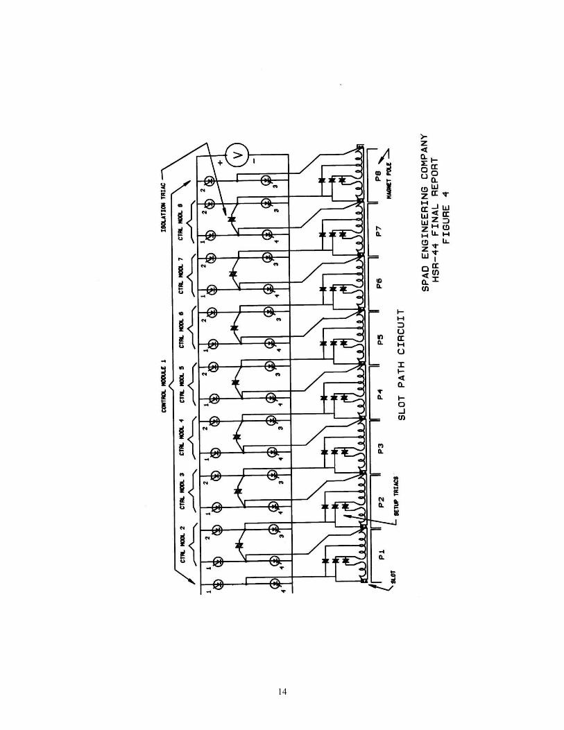
• Figure 3 shows a machine with one highlighted slot path circuit and Figure 4 shows a
schematic slot path circuit. The slot path circuit shown in Figure 4 provides “setup” control features as described in 3.3 above in addition to the basic mode control features described below. Torque capacity is controlled by the number of active slot path circuits and by setup and mode controls. Each setup control sets the number of active turns in slot path circuit coils. In this design Setup 1 has 39 active turns, Setup 2 has 26 turns and Setup 3 has 13 turns. Mode control sets the number of coils connected in series and parallel combinations for each slot path circuit while operating under each setup.
The number of slot path circuits selected for the prototype motor is 10. This will provide torque/speed control resolution of about 7 percent at slow speed while driven at rated voltage of 600 VDC with all slot path circuits in Control Mode 1. Control resolution at intermediate speeds will be about 2 percent with different slot path circuits in different control modes. Finer resolution of about 1 percent at very slow speeds may be effected by reducing system voltage to discrete levels of 1/2 or1/4. All slot path circuits will be in one setup in accordance with the TE capacity required. Therefore once all slot path circuits are in a given setup TE and speed will be controlled by Mode control within the range provided by each setup block shown in Figure 1.
Control modes determine which control modules have active switches concurrent with their triacs being turned-off. If a triac is on in an intermediate control module, all of the

12
module's switches are inactive (maintained in the off state by an overriding signal or circuit condition); if the triac is off, the module's switches are active by permissive control. The following description considers slot path circuits in one of three Setups. The referenced “triac” is the one connected between the two “H” bridge legs in a control module. Other triacs shown in Figure 4 are used to select the number of active turns of slot path circuit coils in a Setup. Setup control of active turns in a coil shall have only one triac on with the other two triacs off. All coils in all slot path circuits shall be in the same Setup at a time.
• The slot path circuit control specifications for the prototype traction motor are very similar
to those of another prototype previously done under a Navy contract. The Contractor retained the “Navy motor” (as will be mentioned hereinafter) under a CRADA with the Navy as a test and demonstration platform for future application developments. With Navy sanction slot path circuit control modules from the Navy motor could be used to perform preliminary tests in support of this prototype traction motor development. However, new hybrid analog/digital control boards for the control modules had to be designed and fabricated to support differences in the control requirements of the traction motor including the above described Setup control feature that is not used or required by the Navy motor.
The Control Modules form what is defined as the “internal control shell” formed by the control modules illustrated in Figure 4 for the slot path circuit. All slot path circuits will be identical and will be controlled as a group by an "external control shell" to be specified later. The control features described in this specification will be hardwired and integrated in the control modules with the exception of a Hall position sensing system. When the motor is in motion all slot path circuit control transitions including those for sequential commutation and changes in Setup and Mode control will be without interruption or discernible torque pulsations. Motion control will be smooth and transparent to the human operator.
13
14

15
• Specifications and design were developed for the architecture and components of an “external control shell”. The external control shell is practically identical to those previously developed to control other motors such as a proof motor and the Navy motor. The only difference relates to the number of slot path circuits controlled. The external control shell provides the interface between the human operator and the internal control shell comprised by the above described control modules. The manual interface will be made of five switches that control SETUP, STOP, START FORWARD, START REVERSE and an UP/DOWN single pole, double throw that switches slot path circuits on and off, and changes control modes for one slot path circuit at a time. This may be done by an imbedded eight bit microprocessor or an up/down ring counter. The latter option is taken for the motor prototype of this contract which will adequately support required testing. This will consist of a control printed circuit board (PCB) piggybacked on a system board. The system board will provide interface to the control modules through 10 shielded ribbon control cables that control the 10 slot path circuits in the prototype motor. The basic external control shell board will support shop tests of the prototype motor. As mentioned, all motion control will be smooth and transparent to the human operator with the exception of limited status indication by an LED array.
• The above described control systems and components were thoroughly tested by computer
simulations and by instrumented bench tests prior to integration in a motor. Then the control system was functionally tested in-house using a proof motor. The proof motor is a smaller scale (82 HP) specimen of the slot path concept originally built and owned by the Contractor to proof the control systems of the Navy motor and other development projects. In-house tests of the slot path control system using the proof motor were successful. Tests using the Navy motor had limited and short lived success resulting from failures of the power sections of control modules.
• The controller uses commercially available solid state power control modules as
prescribed in the application criteria provided by manufacturers. Motor coils store energy in proportion to coil inductance (L) and the square of the current (i2) that flows through them. This energy must be removed and disposed off when the current flow through a coil is interrupted or turned off. At turn off the current rate of change (di/dt) is critical because of induced overvoltage that is proportional to the product of coil inductance L and di/dt (L* di/dt). The magnitude of di/dt is inversely proportional to turn-off time. For example, a turn-off time of 1 microsecond will magnify the product of current i times inductance L by a million. That is, the resulting induced voltage would be destructive unless a dissipation means exists. The volumes and heat capacities of solid state power switch wafers are too small to internally dissipate energy for any length of time. Consequently the turn-off times of available switches, such as mos controlled thyristors (MCT), insulated gate bipolar transistors (IGBT), etc. must by very short, in practice about one microsecond.
Suppression of overvoltage conditions by providing a means of dissipation is constrained by the same L* di/dt effect, in this case the inductance of the drain path through the supply bus. That is, under a high rate of change the supply bus impedance becomes too high to drain coil energy with tolerable overvoltage levels. Thus to have extremely low bus inductance the structure and size of the bus must be minimized. Existing commercial power modules are typically restricted to supply bus areas barely covered by the modules. Application criteria are typically based on use of capacitive snubbers and storage capacitors as inductance canceling elements and low impedance energy drains. Those power modules consist of three half bridges to function as three phase inverters. Three phase motors have distributed phase windings, each winding connected to two half bridges
16
in a delta configuration. The half bridges are switched sequentially so that there is always at least one winding to serve as a discharge path when others are switched. This does not happen with a slot path circuit. Thus the measures used under the application criteria for those three phase inverter modules proved only partially effective when used on slot path circuits, particularly related to the magnitudes of coil inductances and the amounts of stored energy that must be removed from those coils during switching events. They worked well enough for the lower values of the proof motor but not under the much higher values of the Navy motor. Therefore, work is still in progress to find coil energy discharge and dissipation measures that work under the slot path concept.
5.2 Test Results and Problems Encountered Successful test results of a much larger motor developed for the U.S. Navy that employs the same general slot path concept are a prerequisite for completion and testing of the traction motor. All functional features of the motor control system were successfully tested on a small proof motor previously developed to serve as a preliminary test platform for the Navy motor development project. Functional tests of the Navy motor showed failures of power control modules when exposed to its larger winding inductances. The key difference between the Navy motor and the proof motor is in the magnitudes of coil inductances and the amounts of stored energy that must be removed from the coils during switching events. Those of the Navy motor are about one order of magnitude higher, which resulted in voltage stress failures of gate insulation in tests done with modules made of either MCT or IGBT power switches as explained above. Commercially available power control modules used under the application criteria for which they were originally developed proved inadequate for use in the slot path concept architecture as described after the last bullet in 5.1 above. There is a common failure mode that is related to energy stored in the inductance of the slot path circuit coils, the energy discharge path and the short (1 µsec) turn-off time of the solid state switches of the power modules. Several options to resolve this conflict of application have been determined and actions are underway to incorporate and test the best workable option. Once the necessary modifications to the power controller have been evaluated in-house, testing of the Navy motor will be completed which will support completion of construction and testing of the traction motor. 5.3 Other Problems Encountered The prototype motor has a rotor core with permanent magnet poles consisting of three 4 inch sections axially arranged as described in 5.1, fifth bullet. The permanent magnet assemblies in all three rotor sections were partially destroyed as the result of procedural errors. The first errors were made by the permanent magnet manufacturer that did the assemblies by using an epoxy bonding agent of inadequate temperature stability and by shipping the assembled rotor sections without magnetic shielding. On receipt inspection, after noticing the absence of magnetic shielding, instructions were given to the shop activity to not take the assemblies out the shipping crates until protective measures would be taken. The shop activity had instructions requiring all handling of the magnetized rotor assemblies to be done with magnetic shielding in place, particularly for personnel safety. The work order also required the installation of a phosphor-bronze sleeve on each section before the rotor core sections would be assembled on the motor shaft. Those instructions were ignored. The shop activity proceeded to install the rotor core assemblies on the motor shaft without shielding or the required phosphor-bronze sleeve. When all three rotor sections at the same time were placed in an oven preheated to 250 deg. F about half of the magnet pole pieces were destroyed. Each magnet pole was designed with an arcuate span of 6.58 inches. The PM manufacturer made

17
each pole in four pieces to be bonded to the rotor core with epoxy. A basic rule in magnetism is that same poles repel and opposite poles attract - with many tons of force in the case of high energy permanent magnets. Another less known rule is that a permanent magnet behaves differently at an air interface boundary vice within a high permeance magnetic circuit as it would be when finally installed in an electric machine. Thus, with an air interface boundary the four magnet pieces would have high repulsion forces restrained only by the epoxy bonds. When the restraining epoxy bonds were lost by heating, the repulsive magnet pieces of same polarity flipped over, attracted to the nearest opposite pole piece. In doing so they struck hard with tons of force destroying themselves as well as the stuck pieces of opposite polarity. The hardness of the magnet material makes it brittle so that when subjected to asymmetric impact under tons of force damage is unavoidable. This does not happen under normal installation and operating conditions in an electric machine even when the machine is subjected to shock and vibration. When installed in an electric machine or when not installed but protected by magnetic shielding (that follows the old magnet keeper principle) all magnet pieces are drawn to the rotor core by tons of force regardless of polarity. The huge contact forces of tons per square inch then become the primary support factor to the magnet pieces. The huge magnetic contact forces exceed any anticipated stress loads that may be produced by shock or vibration. As an example, the above mentioned Navy motor that has a much larger rotor was successfully assembled with minimum effort and without difficulty. The explanations above are supported by FEA models done to serve as formal technical backup but not included herewith. 6. Project Panel A panel of experts is established for all IDEA projects to provide guidance and support for the research. Panel members are typically selected for their technical expertise and expertise in representing the perspective of the end user. Panel members for this project were Robert J. McCown, P.E. FRA (retired) who is a member of the HSR-IDEA Committee; Nick Rivera, the principal investigator; and Chuck Taylor, the IDEA project manager. The panel met several times during the early stages of the contract to review the concept and the results of computer simulations and to witness the operation of a small proof motor that was built using the slot path/permanent magnet concept. As a result of these meetings, the panel concluded that design, fabrication, and testing of a full-scale traction motor prototype were justified. Panel members subsequently had numerous meetings, telephone conversations and email exchanges to provide guidance and support to the principal investigator during the design, fabrication and testing of the prototype. 7. Conclusions The objectives of this project are to build and test a prototype traction motor to demonstrate the capabilities of a new electric machine technology that uses high energy permanent magnets as applied to electric rail traction. The prototype core and controller will be installed in the housing of a General Motors model D77 traction motor to use its performance characteristics for a GP38-2 locomotive as a means of comparison. The new technology is claimed capable of optimum utilization of motor space and materials for best torque-speed performance with the advantage of having much reduced unsprung mass when directly mounted on a wheel axle. This project has met significant milestones toward accomplishment of its objectives as follows. • The prototype traction motor design, supported by accurate FEA computer models far
exceeds the original GM D77 continuous TE capacity over a much wider speed range of 1 to 113 mph while driven at a voltage of 600 VDC. Of significant value is its continuous slow speed capability while under a TE load capacity that is 38 percent higher. Similarly TE capacity at 113 vice 65 mph is 111 percent higher and low and high speed electrical

18
losses are about 75 percent lower than those of the original GM D77 motor. • The prototype traction motor core components were successfully designed and built to fit
in the adapted GM D77 housing with ample space to spare and to also house the motor controller with weight reduced to about 1/2 of the original GM D77 motor weight, including housing.
• All functional features of the motor control system were successfully tested using a smaller
proof motor. Tests of the control system on a larger motor built under a Navy project showed several failures of the solid state power switches of control modules when exposed to stored energy discharged from its larger winding inductances. Commercially available power control modules used under the application criteria for which they were originally developed proved inadequate for use in the slot path concept architecture of this motor technology. Several options to resolve this application conflict have been determined.
8. Plans for Implementation Plans for implementation should obviously start with completion and shop testing of the prototype traction motor. The prototype is designed to be capable of direct installation in a GP38 locomotive. A future phase for evaluation on a locomotive may be defined for industrial validation testing. Ideally, to fully demonstrate the improved motor performance the locomotive should be fitted with four identical motors. Performance matching of the new technology motor with the existing motors would not be cost effective and would curtail the full capabilities of the new technology motor when limited to match the performance of the existing ones. Therefore, the future phase plan should include construction of three additional prototype motors and engineering adaptation of the locomotive controls to work with the new motors. Program and test plans using a technology upgraded GP38 locomotive for industrial validation should be prepared, resources identified and arrangements made with government and/or industry for support. 9. REFERENCES [a] 1994 Institution of Electrical Engineers
Title: A comparison of locomotive drives using current-forced AC traction motors Author: McLean, G. W.
[b] 1994 Institution of Electrical Engineers Title: Design assessment and implementation potential of Three phase asynchronous AC traction motor systems for North America Authors: Anderson, G. B. and Peters, A. J. [c] 1995 IEEE/ASME Joint Railroad Conference Title: AC Locomotives in North American Service: A Benefits Assessment Author: Randolph R. Resor