system and installation manual - repeater builder ericssonz system and installation manual edacs...
TRANSCRIPT
LBI-38965C
ericssonz
System and InstallationManualEDACS
BCU/CALBilling Correlation Unit/Centralized Activity Logger
LBI-38965C
2
Copyright August 1994, Ericsson Mobile Communications Inc.
NOTICE!
This manual covers Ericsson and General Electric products manufactured and sold by Ericsson Inc.
NOTICE!
Repairs to this equipment should be made only by an authorized service technician or facility designated by the supplier. Anyrepairs, alterations or substitution of recommended parts made by the user to this equipment not approved by themanufacturer could void the user’s authority to operate the equipment in addition to the manufacturer’s warranty.
NOTICE!The software contained in this device is copyrighted by Ericsson Inc. Unpublished rights are reserved under the copyrightlaws of the United States.
This manual is published by Ericsson Inc., without any warranty. Improvements and changes to this manual necessitated by typographical errors,inaccuracies of current information, or improvements to programs and/or equipment, may be made by Ericsson Inc., at any time and without notice. Suchchanges will be incorporated into new editions of this manual. No part of this manual may be reproduced or transmitted in any form or by any means,electronic or mechanical, including photocopying and recording, for any purpose, without the express written permission of Ericsson Inc.
LBI-38965C
3
TABLE OF CONTENTS
Page
1. INTRODUCTION............................................................................................................................................................ 5
1.1. BCU FUNCTIONAL DESCRIPTION................................................................................................................... 6
1.2. CAL FUNCTIONAL DESCRIPTION................................................................................................................... 6
2. PHYSICAL DESCRIPTION AND COMPATIBILITY .................................................................................................. 9
2.1. PHYSICAL SPECIFICATIONS............................................................................................................................ 9
2.2. BCU/CAL ARCHITECTURE.............................................................................................................................. 10
2.3. COMPATIBILITY............................................................................................................................................... 12
3. SPECIFICATIONS ........................................................................................................................................................ 13
3.1. COMMON BCU AND CAL OPERATIONAL SPECIFICATIONS................................................................... 133.1.1. EDACS System Interface ........................................................................................................................... 133.1.2. Throughput ................................................................................................................................................. 133.1.3. Hard Disk Interface .................................................................................................................................... 133.1.4. Operator Interface ...................................................................................................................................... 13
3.2. BCU OPERATIONAL SPECIFICATIONS......................................................................................................... 133.2.1. Subscriber Attribute Database.................................................................................................................... 133.2.2. Billing Architecture .................................................................................................................................... 143.2.3. BCU Operation Overview .......................................................................................................................... 14
3.2.3.1. RF Channel Usage (Air Time).......................................................................................................... 153.2.3.2. Conversations................................................................................................................................... 153.2.3.3. Group Billing Mode ......................................................................................................................... 153.2.3.4. Input Messages................................................................................................................................. 153.2.3.5. Time Synchronization ...................................................................................................................... 163.2.3.6. Output Records................................................................................................................................. 163.2.3.7. BCU Configuration Files.................................................................................................................. 163.2.3.8. Operator Functions........................................................................................................................... 173.2.3.9. Database Elements ........................................................................................................................... 173.2.3.10. Call Processing............................................................................................................................... 183.2.3.11. Call Detail Records ........................................................................................................................ 18
3.3. CAL OPERATIONAL SPECIFICATIONS......................................................................................................... 193.3.1. System Manager Interface .......................................................................................................................... 193.3.2. Protocol Supported..................................................................................................................................... 193.3.3. CAL Operation Overview........................................................................................................................... 203.3.4. Additional Product Features ....................................................................................................................... 20
LBI-38965C
4
TABLE OF CONTENTS (Cont.)
Page
4. INSTALLATION ........................................................................................................................................................... 21
4.1. HARDWARE INSTALLATION.......................................................................................................................... 21
4.2. SOFTWARE INSTALLATION........................................................................................................................... 224.2.1. Distribution Media...................................................................................................................................... 22
4.2.1.1. User Configuration Files................................................................................................................... 23
4.2.2. Initial Installation........................................................................................................................................ 274.2.2.1. First-Time Configuration.................................................................................................................. 314.2.2.2. System Disk Booting ........................................................................................................................ 334.2.2.3. Proper System Shutdown.................................................................................................................. 34
4.2.3. Software Upgrades...................................................................................................................................... 35
4.3. CAL TERMINAL SERVER CONFIGURATION ............................................................................................... 35
5. EDACS NETWORK MANAGEMENT SUPPORT BY THE BCU/CAL ..................................................................... 39
5.1. NETWORK MANAGER CONFIGURATION.................................................................................................... 39
5.2. MIB-II SUPPORT ................................................................................................................................................ 40
5.3. COMMON EDACS MIBS ................................................................................................................................... 41
5.4. EDACS COMMON MANAGED ELEMENT PARAMETERS .......................................................................... 425.4.1. Implementation Limits................................................................................................................................ 42
5.5. EDACS ALARM-THRESHOLD ......................................................................................................................... 425.5.1. Implementation Limits................................................................................................................................ 425.5.2. Default Threshold Alarms........................................................................................................................... 43
5.6. EDACS SITE PERFORMANCE.......................................................................................................................... 43
5.7. SNMP TRAP SUMMARY................................................................................................................................... 435.7.1. Generic Traps ............................................................................................................................................. 435.7.2. EDACS101 Traps....................................................................................................................................... 445.7.3. EDACS102 Traps....................................................................................................................................... 44
5.8. MULTISITE MONITOR...................................................................................................................................... 44
5.9. SECURITY MANAGEMENT ............................................................................................................................. 45
APPENDIX A EDACS BILLING (CDR) FORMAT........................................................................................................A-1
APPENDIX B TRAFFIC ANALYSIS STATISTICS ....................................................................................................... B-1
APPENDIX C PHYSICAL CONFIGURATION DETAILS............................................................................................. C-1
APPENDIX D FAULT TOLERANCE..............................................................................................................................D-1
INTRODUCTION LBI-38965C
5
1. INTRODUCTION
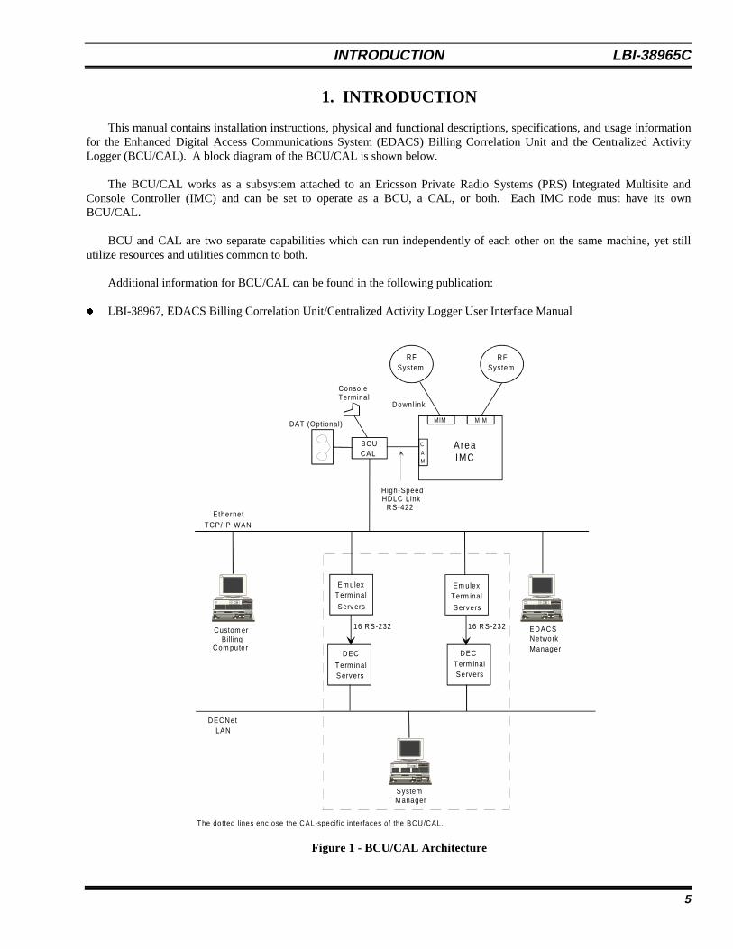
This manual contains installation instructions, physical and functional descriptions, specifications, and usage informationfor the Enhanced Digital Access Communications System (EDACS) Billing Correlation Unit and the Centralized ActivityLogger (BCU/CAL). A block diagram of the BCU/CAL is shown below.
The BCU/CAL works as a subsystem attached to an Ericsson Private Radio Systems (PRS) Integrated Multisite andConsole Controller (IMC) and can be set to operate as a BCU, a CAL, or both. Each IMC node must have its ownBCU/CAL.
BCU and CAL are two separate capabilities which can run independently of each other on the same machine, yet stillutilize resources and utilities common to both.
Additional information for BCU/CAL can be found in the following publication:
l LBI-38967, EDACS Billing Correlation Unit/Centralized Activity Logger User Interface Manual
Figure 1 - BCU/CAL Architecture
Custom erBilling
Em ulexTerm inal
Serv ers
Em ulexTerm inal
S ervers
DEC
Term inalS ervers
DECTerm inalServ ers
16 RS-232 16 RS-232
DECNetLAN
SystemM anager
Com pute r
EDACSNetworkM anager
The do tted lines enc lose the CAL-specif ic interfaces of the BCU/CAL.
ConsoleTerminal
High-SpeedHDLC Link
DAT (Optional)
TCP/ IP WAN
BCU
RFSystem
RFSystem
AreaIMC
MIM MIM
C
AM
Downl ink
Ethernet
CAL
RS-422
LBI-38965C INTRODUCTION
6
1.1. BCU FUNCTIONAL DESCRIPTION
The main function of the BCU is to generate call detail records (CDRs) to be transferred to an external billing system forinvoice generation. To accomplish this, the BCU scans an input stream of activity messages supplied by the IMC, archivesthese messages in their raw form, uses those messages which indicate channel assignment and channel drop events to calculateair time, and then generates the CDR.
Call Types Supported
All EDACS call types except for the following are supported by the BCU:
1. Console calls.2. Conventional site calls.3. Local interconnect calls.4. System all calls.
Non-EDG data calls are supported only if radios are “wide-area enabled” on the site.
1.2. CAL FUNCTIONAL DESCRIPTION
EDACS system administrators require both site monitor and activity download capabilities. These functions are normallysupported by the System Manager in conjunction with the Site Controller at each Radio Frequency (RF) System. The CALprovides this capability for EDACS networks not equipped with a Site Controller.
1. Site MonitorProvides the system operator at a System Manager terminal with a real-time display of the calls in progress on the RFchannels at the selected trunked system.
2. Activity DownloadCall activity and system status information are collected by the CAL and buffered in internal memory. Once anoperator-defined buffer content threshold is exceeded, the CAL initiates a download of buffer contents to the SystemManager. The downloaded information is used to prepare traffic reports on system usage.
In existing EDACS networks, the System Manager communicates with Site Controllers at RF systems using modems anddial-up or leased line connections, routed through a DECServer terminal server. A communications session is set up via aDECServer port between the System Manager and the Site Controller. The System Manager associates the DECServerphysical port number with the Site Controller's identity.
Since the IMC is already connected to all the sites, it has centrally available much of the data that individual SiteControllers normally output to the System Managerfor all the sites. The CAL connects to the IMC and demultiplexesincoming call activity information messagesthe same messages that the BCU uses for billinginto activity download dataand site monitor data to send to a System Manager using Site Controller protocol.
The CAL uses two Internet Protocol (IP) terminal servers on the local area network (LAN) to communicate with theSystem Manager's DECServer(s). Up to 32 RS-232 asynchronous serial connections are available, 16 per terminal server.One System Manager DECServer port and one IP terminal server port are required per EDACS system being monitored byCAL.
NOTE
INTRODUCTION LBI-38965C
7
Call Types Supported
All EDACS call types except for the following are supported by the CAL:
1. Console calls.2. Conventional site calls.3. Local interconnect calls.4. System all calls.
Non-EDG data calls are supported only if radios are “wide-area enabled” on the site.
NOTE

LBI-38965C INTRODUCTION
8
This page intentionally left blank

PHYSICAL DESCRIPTION AND COMPATIBILITY LBI-38965C
9
2. PHYSICAL DESCRIPTION AND COMPATIBILITY
This section outlines the specifications, depicts the physical architecture, and provides compatibility information for theBCU/CAL.
Software for the BCU and the CAL are merged into one software package. Feature encryption allows or disallows BCUor CAL functionality. The two products can also run on the same hardware platform with minor additions for CAL.
2.1. PHYSICAL SPECIFICATIONS
General Specifications
BCU/CAL:ELMA VME System 12 7-slot enclosure with PSU and integral cooling fanTVME 147 single-board computer with TVME 712/M Transition ModuleFormation WANServer fv53101.2 GB 3½" half-height 8.5ms hard disk drive, internal (SCSI ID 2)1.44 MB 3½" half-height floppy disk drive, internal (SCSI ID 1)
Tape Drive (Optional with BCU only):4/8 GB 3½" half-height 4mm digital audio tape (DAT) drive, internal (SCSI ID 3)(Recommended Archive/Maynard 4324NP)
Console Terminal:DEC VT100 or compatible console terminal
Terminal Servers (CAL only)Emulex Performance Series P2516-SLTL (16 ports per terminal server)
Power Supply
BCU/CAL:115/230 VAC, 47-63 Hz, 500 W
Physical (EGE Standard Cabinet)
BCU/CAL:6 rack units: 26.67 cm (10.5 in.) high x 48.26 cm (19 in.) wide x 49.99 cm (19.68 in.) deep
Environmental
Storage Temperature: -40 to +85°COperating Temperature: 0 to 40°C (ambient)Operating Altitude: < 15,000 feetShipping Altitude: < 50,000 feetRelative Humidity: < 90% (non-condensing)
LBI-38965C PHYSICAL DESCRIPTION AND COMPATIBILITY
10
2.2. BCU/CAL ARCHITECTURE
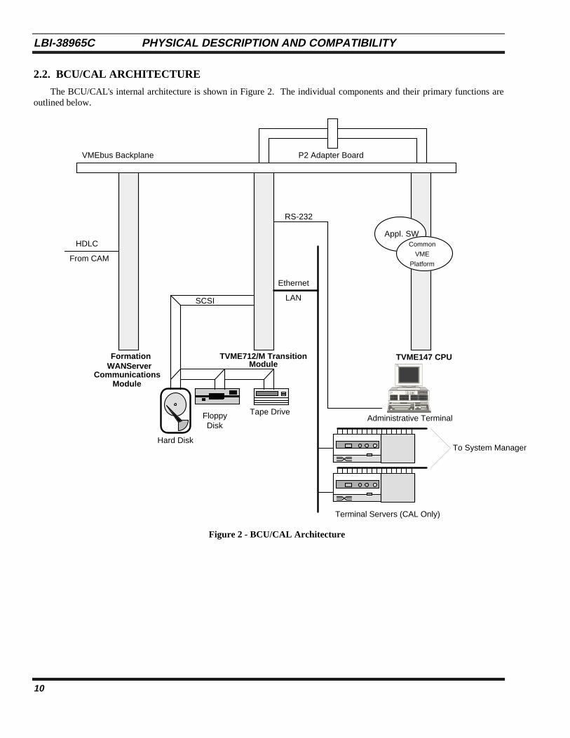
The BCU/CAL's internal architecture is shown in Figure 2. The individual components and their primary functions areoutlined below.
Figure 2 - BCU/CAL Architecture
TVME712/M TransitionModule
CommunicationsModule
Hard Disk
FloppyDisk
From CAM
Tape Drive
SCSI
Appl. SWHDLC
RS-232
Ethernet
LAN
P2 Adapter BoardVMEbus Backplane
Common
VME
Platform
Terminal Servers (CAL Only)
To System Manager
WANServerFormation TVME147 CPU
Administrative Terminal
PHYSICAL DESCRIPTION AND COMPATIBILITY LBI-38965C
11
The BCU/CAL is based on a VMEbus computing platform with the following components:
CPU
Technico TVME 147 single-board computer based on a 68030 microprocessor
• Supports BCU/CAL application processing• Interfaces to hard disk, floppy disk, and tape drive via an on-board small computer systems interface (SCSI)
with a connector on the transition module• Interfaces to the console terminal via an RS-232 serial port with a connector on the transition module• Network physical connection is 802.3 Ethernet, 10 BASE-15 (Thick Wire). A MAU may be used for
connection to a Thin Wire (coaxial) network
Internal Drives
Hard Disk: 3½" 1.2 GB
• Provides configuration parameter storage• Provides call detail record (CDR) storage• Provides raw activity record (RAR) buffering/storage
Floppy Disk: 3½" 1.44 MB
• Used for application program updates
Tape: 3½" 4/8 GB 4mm DAT
• Provides call detail record (CDR) file archival storage• Provides general purpose file interchange with UNIX• UNIX Tar format, 512-byte tape block size, no data compression
Communications Module
Formation WANServer fv5310
• Interfaces the BCU/CAL via high-speed high-level data link control (HDLC) link to the Central Activity Module(CAM) in the Integrated Multisite and Console Controller (IMC)
System Manager Interface (CAL only)
One or Two Emulex Performance Series P2516-SLTL Terminal Servers
• Communicates with the BCU/CAL over the network and with the System Manager over RS-232• Converts between Transmission Control Protocol (TCP) sockets and asynchronous serial protocol
LBI-38965C PHYSICAL DESCRIPTION AND COMPATIBILITY
12
2.3. COMPATIBILITY
The BCU/CAL software is compatible with the following IMC and System Manager versions:
• IMC Software V4.01 and later• IMC CAM Controller Board (P/N 19D903299P3)• Networks/Data VME Controller ROM V1.03• MicroVax System Manager Software V3.01 and later (CAL only)
The System Manager Software version requirement applies only to the CAL feature. The BCU feature operatesindependent of the System Manager. Thus, the BCU is “compatible” with any System Manager softwareversion.
Backwards Compatibility
The BCU/CAL will function with IMC software versions down to V3.04, with minor performance degradation. Thefollowing features are not available with IMC software versions older than V4.01:
BCU/CAL• The User Interface stats command will not provide information regarding queued, denied, system busy, and convert-
to-callee channel events.
CAL-Specific• Activity records and site monitoring will not reflect queued, denied, system busy, and convert-to-callee channel
events.• The site monitor will not provide current control channel indication.
SPECIFICATIONS LBI-38965C
13
3. SPECIFICATIONS
3.1. COMMON BCU AND CAL OPERATIONAL SPECIFICATIONS
3.1.1. EDACS System Interface
The BCU/CAL interfaces to EDACS via a full duplex port supporting high-level data link control (HDLC) protocol. TheBCU/CAL will adapt to the data transmission rate to which the Central Activity Module (CAM) is set to operate (64K or360K, selectable via CAM dip switches).
BCU/CAL Input Data
Each raw activity record (RAR) contains the following information:
1. Day and time of event accurate to ±0.1 second2. Type of event (i.e., assignment or drop)3. Call type (individual clear voice, group clear voice, individual digital voice, group digital voice, data, etc.)4. Site number or console number5. Channel number (to match assignments with drops)6. Caller ID7. Callee ID8. Digitally dialed PSTN digits for outgoing interconnect calls
The dialed digits correspond to the digits sent by a radio to the interconnect system to initiate an interconnect call; dualtone multi-frequency (DTMF) overdial digits sent by the radio once an interconnect call is in progress are not registered bythe BCU.
3.1.2. Throughput
The BCU/CAL's interface to the IMC is capable of receiving a peak data rate of 192 raw activity records (RARs) persecond. A buffer stores incoming RARs at the peak rate of 192 RARs per second for a minimum of 300 seconds (5 minutes).
3.1.3. Hard Disk Interface
The BCU/CAL provides nonvolatile storage of the BCU/CAL operating software, CDRs, system configuration data,system defaults, and subscriber attributes. The hard disk provides concurrent support of call record processing and theoperator interface.
3.1.4. Operator Interface
Most BCU/CAL operator functions are capable of being performed without impacting or reducing the capacity of the callprocessing functions below specified rates. Refer to the User Interface Manual, LBI-38967, for further information.
3.2. BCU OPERATIONAL SPECIFICATIONS
This section outlines the specifications that are unique to the BCU personality.
3.2.1. Subscriber Attribute Database
Each system subscriber and each group defined on the system is assigned a record in the subscriber attribute database.This database supports a maximum of 16,383 individual subscribers and a maximum of 2048 groups.
LBI-38965C SPECIFICATIONS
14
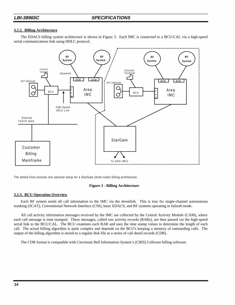
3.2.2. Billing Architecture
The EDACS billing system architecture is shown in Figure 3. Each IMC is connected to a BCU/CAL via a high-speedserial communications link using HDLC protocol.
ConsoleTerminal Termina l
Conso le
H igh-SpeedHDLC L ink
DAT (Optional) DAT (Optional)
Cus tomer
Bil l ing
Main f rame
T C P / I P W A N
B C U
RFSystem
RFSystem
RFSystem
AreaIMC
M I M M I M
C
A
M
Downl ink
B C UC
AM
AreaIMC
M I M M I M
StarGate
To o ther IMCs
RF
System
Ethernet
The dotted l ines enclose one optional setup for a StarGate (mult i-node) bi l l ing architecture.
Figure 3 - Billing Architecture
3.2.3. BCU Operation Overview
Each RF system sends all call information to the IMC via the downlink. This is true for single-channel autonomoustrunking (SCAT), Conventional Network Interface (CNI), basic EDACS, and RF systems operating in failsoft mode.
All call activity information messages received by the IMC are collected by the Central Activity Module (CAM), whereeach call message is time stamped. These messages, called raw activity records (RARs), are then passed via the high-speedserial link to the BCU/CAL. The BCU examines each RAR and uses the time stamp values to determine the length of eachcall. The actual billing algorithm is quite complex and depends on the BCU's keeping a memory of outstanding calls. Theoutput of the billing algorithm is stored to a regular disk file as a series of call detail records (CDR).
The CDR format is compatible with Cincinnati Bell Information System’s (CBIS) Cellware billing software.
SPECIFICATIONS LBI-38965C
15
3.2.3.1. RF Channel Usage (Air Time)
The basic unit of RF channel usage for billing purposes is a channel assignment. One or more working RF channels isassigned in response to a request from a subscriber unit (mobile radio, data terminal, etc.). Each channel assignment eventresults in air time, which is defined as the period of time during which the RF channel or group of channels is in use, repeatingthe signal from a subscriber unit. If the system is operating in transmission trunked mode, one channel assignment occurseach time the unit is keyed and unkeyed. In a multisite network, more than one channel assignment can occur in a singlecall—since multiple sites can participate in a call—and a channel is used on each participating site. The air time for such acall is defined as the sum of the air time associated with all of the channel assignments occurring in that call.
In a multiple node network (StarGate or MultiLink), a single call may involve channel assignments on sites on more thanone node. In theory, these channel assignments are part of the same call. In practice, the BCU deals with data at the nodelevel and does not correlate channel assignment air time from remote nodes. A multiple node call is identified by theStarGate interface ID as the site ID in the CDR; this facilitates the correlation of records across nodes in the external billingsystem.
3.2.3.2. Conversations
If a CDR were created for each call, the data storage requirements for the BCU/CAL would be excessive. For thisreason, a different unit of RF channel usage, called a conversation, has been defined. A conversation includes one or morecalls. Calls are summed into conversations based on the subscriber (radio) units participating in the calls and the duration ofthe time interval between the end of one call and the beginning of the subsequent call. The criteria for inclusion in aconversation are explained in detail below.
Grouping Calls
A set of calls may be grouped into a conversation only if each call involves the same participants and is of the same calltype as all other calls in the set. For group calls, only calls made with the same Group Identification (GID) may be linked. Inthis case, the Logical Identification (LID) of the caller is irrelevant, except for the LID of the first caller in a sequence (this isexplained in the next subsection). For individual calls, the caller's LID must be the same as either the caller's or the callee'sLID in every other call in the set.
Broken Call Sequences
A set of calls must occur in an unbroken sequence. A sequence is broken when one of the call participants calls a non-participant. For individual calls, this means that either the caller or the callee from the first call in the sequence calls somethird party, either a group or individual. For group calls, the sequence is broken if the caller from the first call in the sequencecalls a different group or an individual. Note that a subscriber unit may participate in multiple group conversationsoverlapping in time, as long as that unit was not the first caller in at least one of the conversations.
A sequence of calls is also broken when the time interval separating the end of one call and the beginning of thesubsequent call in the sequence exceeds an arbitrary value. This value is called the pseudo hang time and is configurable on aunit or group basis in the BCU.
3.2.3.3. Group Billing Mode
A group call may be charged to the caller or to the group. The CDR includes a flag indicating which party to bill. Thechoice is determined by a billing mode associated with each group ID or by the default billing mode. Individual calls arealways charged to the caller, except for land-to-mobile interconnect calls and incoming data calls. In each of these cases, theID of the caller (or sender of the data) is unknown; thus, the call must be billed to the callee.
3.2.3.4. Input Messages
Input to the BCU consists of a stream of activity messages. As a minimum, the messages include all channel assignmentevents and channel drop events generated on EDACS. This includes channel assignment and drop from the Jessica PrivateBranch Exchange (PBX) Gateway and StarGate interfaces.
LBI-38965C SPECIFICATIONS
16
Channel assignment and channel drop messages contain the following information:
• Date and time of event to the nearest tenth of a second• Type of event (i.e., assignment or drop)• Call type (individual clear voice, group clear voice, individual digital voice, group digital voice, data, etc.)• Site number or console number• Channel number• Caller ID• Callee ID
3.2.3.5. Time Synchronization
The time of channel event value is derived from the IMC's internal clock. This is slaved to the CEC/IMC Manager clock,which can be synchronized externally from a WWVB signal, via a Spectracom clock unit. This unit is available as an optionfor the CEC/IMC Manager. The Spectracom unit includes an internal high-stability reference clock, which maintainssynchronization even in the event of loss of the WWVB signal for an extended period. This configuration ensures that RARtimestamps are accurate at all times.
3.2.3.6. Output Records
The BCU creates CDRs by processing the input messages due to channel assignments and channel drops. The format ofa CDR record entry is discussed in detail in Appendix A. Each CDR records the following information about eachconversation:
• The Logical Identification (LID) of the caller• The identity of the callee (either LID or GID)• The location (node, site, and channel number) of each RF channel involved in the conversation• The call type (individual clear voice, group clear voice, individual digital voice, group digital voice, data, etc.)• A flag indicating which party to bill (caller or callee)• The start time of the first call• The elapsed time from the start time until the end of the final call• The number of channel assignments included in the conversation• The total accumulated air time (Note that this is not the same as the elapsed time because of the pseudo hang
time, and the effect of multiple channels per call.)
3.2.3.7. BCU Configuration Files
The BCU uses binary configuration files to store various configuration values. The file names and their contents are asfollows:
File Name Contents
SYSTEM.BIN Specifies system parameters, default pseudo hang times, and billing modes.
UNIT.BIN Specifies the pseudo hang time associated with each LID.
GROUP.BIN Specifies the pseudo hang time and the group billing mode associated with each GID.
These files are located in the 1.2/cnfg directory.
Since they are stored in binary form, these configuration files can be modified only by using the BCU/CAL ConfigurationService (BCS) program, which is described in the User Interface Manual (LBI-38967). The BCU is able to operate with noterminal input by using all default values for configuration parameters.
Pending development by Ericsson Inc. of a system-wide database management strategy, there is a method by which theBCU configuration "database" can be maintained without using BCS to configure each unit manually.
SPECIFICATIONS LBI-38965C
17
The three configuration files can be created by running BCS on a BCU/CAL used as a master. Then, these files can becopied to the appropriate directory (1.2/cnfg) on a target BCU, and the target will assume the same configuration values.Changes specific to the target must be made either by running BCS on the target or by making the changes on the master,copying the configuration files to the target, then reversing the changes to restore the master to its baseline configuration.
To copy or delete the configuration files from a BCU/CAL, you must NOT be running BCS on that system. BCS keeps allthe configuration files open while it is running, thereby preventing them from being deleted or overwritten.
3.2.3.8. Operator Functions
An EDACS system operator is able to perform the following functions locally or remotely using a terminal interfaceprogram running on the BCU/CAL:
• Input of default configuration database.• Default pseudo hang time.• Default group billing mode.• Input of configuration data for individual LIDs and/or GIDs to override the default configuration database.
(Configuration data may be input for an individual ID or range of IDs.)- LID pseudo hang time.- GID pseudo hang time.- GID group billing mode.
• Creation of a magnetic tape archive of CDRs.• Transfer CDR files from the hard drive to the floppy drive.
Refer to LBI-38967 for a detailed explanation of the available operator functions.
3.2.3.9. Database Elements
This section describes the elements of the BCU's configuration database.
Default Data
A set of subscriber default attributes maintained on the system contains the following information:
1. Default unit pseudo hang time (seconds)2. Default group pseudo hang time (seconds)3. Default group billing mode (caller or group)4. Default data call pseudo hang time (seconds)
Unit Data
Each subscriber can be assigned a record in the subscriber attribute database. This record contains the followinginformation: Pseudo_Hang-Time (seconds).
Group Data
Each group defined on the system shall be assigned a record in the subscriber attribute database containing the followinginformation:
1. Group pseudo hang time (seconds)2. Billing mode (group or caller)
NOTE
LBI-38965C SPECIFICATIONS
18
3.2.3.10. Call Processing
This section contains specifications on the BCU's call processing capability.
CDR Processing
A record of each conversation is maintained by the system. A conversation is a collection of calls detailed by RARs thathave been correlated based upon call participants and caller pseudo hang time. Each CDR contains the followinginformation:
1. Caller billing ID (BID)2. Callee BID or GID (group ID)3. Call type (individual, group, Digital Voice, data, interconnect, etc.)4. Bill flag (caller or callee)5. Identification of each RF channel (node, site, and channel)6. Start time of the first call7. Number of channel assignments included in the conversation8. Total elapsed time from start time to end of final call9. Total accumulated node air time to within ±0.5 seconds10. PSTN number dialed on outgoing interconnect calls11. PSTN line number on incoming interconnect calls
Call Processing CDR Output
The call processing software redirects file output to a new file when the current file being written to exceeds a maximumsize. The system administrator can set this maximum size.
CDR Storage Requirements
The BCU is capable of storing all CDRs from the previous 30 days on its internal hard drive. CDR files are maintainedon the system for a programmable time period.
CDR Processing Errors
The call processing software recovers automatically from the following error conditions:
1. Link time-out exceeded2. Unmatched channel drops3. Unmatched channel assignments4. CAM hardware reset5. WANServer reset
3.2.3.11. Call Detail Records
A CDR is a series of ASCII characters terminated by a newline (NL) character. The records are variable length, but theycontain a fixed length segment, which is always present, followed by zero or more suffix segments.
There are two types of suffix segments. The first is an additional site segment, which identifies the sites and channelsused in a multisite call. The second type of suffix is a PSTN phone number field, which is appended to a mobile-originatedinterconnect call record and contains the digits dialed by the caller.
SPECIFICATIONS LBI-38965C
19
3.3. CAL OPERATIONAL SPECIFICATIONS
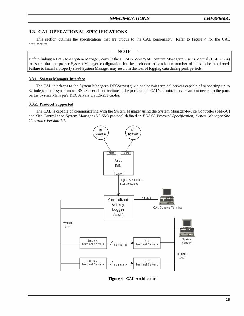
This section outlines the specifications that are unique to the CAL personality. Refer to Figure 4 for the CALarchitecture.
Before linking a CAL to a System Manager, consult the EDACS VAX/VMS System Manager’s User’s Manual (LBI-38984)to assure that the proper System Manager configuration has been chosen to handle the number of sites to be monitored.Failure to install a properly sized System Manager may result in the loss of logging data during peak periods.
3.3.1. System Manager Interface
The CAL interfaces to the System Manager's DECServer(s) via one or two terminal servers capable of supporting up to32 independent asynchronous RS-232 serial connections. The ports on the CAL's terminal servers are connected to the portson the System Manager's DECServers via RS-232 cables.
3.3.2. Protocol Supported
The CAL is capable of communicating with the System Manager using the System Manager-to-Site Controller (SM-SC)and Site Controller-to-System Manager (SC-SM) protocol defined in EDACS Protocol Specification, System Manager/SiteController Version 1.1.
Figure 4 - CAL Architecture
High-Speed HDL C
Link (RS-422)
R FSystem
RFSystem
AreaIM C
M IM M IM
CA M
C en tralizedActivityLog ger(C AL)
RS -232
C AL C onsole T erm ina l
TCP /IPLAN
Em ulex Term inal Serv ers 16 R S-232
D EC Term inal Serv ers
E m ule x Term inal Serv ers 16 R S-232
DE C T erm inal Serv ers
SystemM anag er
DECN etLA N
NOTE
LBI-38965C SPECIFICATIONS
20
3.3.3. CAL Operation Overview
As new RARs enter the system, they are dispatched to an appropriate site handler which reformats and queues the data.When the number of activity records queued exceeds a threshold value obtained from the System Manager at startup, adownload request is sent to the System Manager. At any point, the System Manager may log in to the site object and requestit to purge its queue of activity messages, start/stop download of activity messages, or start/stop the transmission ofmonitoring messages.
3.3.4. Additional Product Features
Network File Server
The BCU/CAL can be licensed to function as a Network File Server (NFS). This feature allows the BCU/CAL system disk tobe mounted by client hosts, such as a billing mainframe computer. The NFS feature is provided at no charge for unitslicensed for BCU operation. It may be purchased as an additional feature for the CAL.
INSTALLATION LBI-38965C
21
4. INSTALLATION
4.1. HARDWARE INSTALLATION
Turn off the power before removing or installing VMEbus boards. Removing or reinstalling the boards while the power is onwill damage the boards.
This section describes the physical installation of the BCU/CAL. Other configuration is performed duringmanufacturing, and the information necessary is provided in Appendix C.
Follow these steps to connect a BCU/CAL to an IMC for the first time (except where indicated otherwise, these stepsapply to all configurations; BCU only, CAL only, or BCU and CAL).
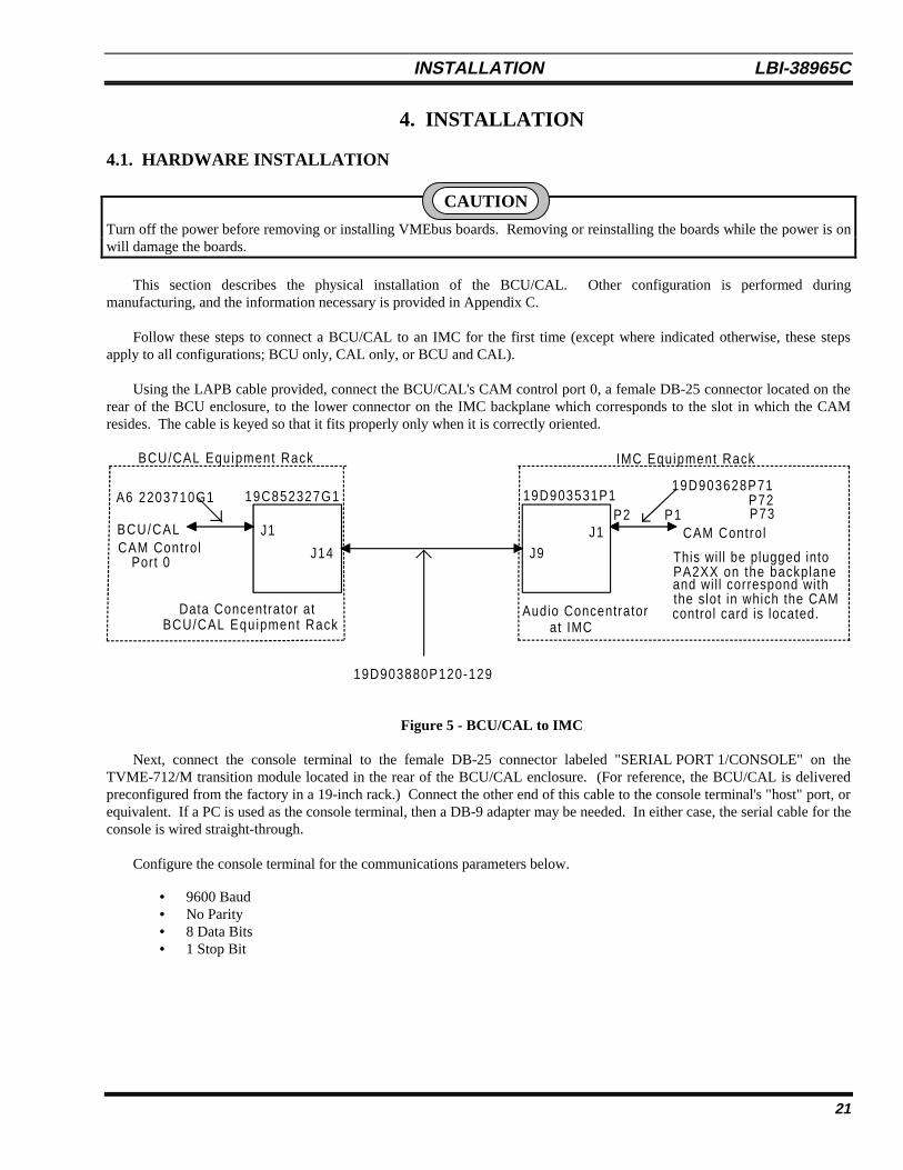
Using the LAPB cable provided, connect the BCU/CAL's CAM control port 0, a female DB-25 connector located on therear of the BCU enclosure, to the lower connector on the IMC backplane which corresponds to the slot in which the CAMresides. The cable is keyed so that it fits properly only when it is correctly oriented.
19D903628P71P72P73
CAM Contro l
Audio Concentratorat IMC
Data Concentrator atBCU/CAL Equipment Rack
P2 P1
19D903880P120-129
BCU/CAL
and wil l correspond with
This wil l be plugged intoPA2XX on the backplane
the slot in which the CAMcontrol card is located.
CAM Contro lPort 0
J1
J14 J9J1
19C852327G1 19D903531P1
BCU/CAL Equipment Rack IMC Equipment Rack
A6 2203710G1
Figure 5 - BCU/CAL to IMC
Next, connect the console terminal to the female DB-25 connector labeled "SERIAL PORT 1/CONSOLE" on theTVME-712/M transition module located in the rear of the BCU/CAL enclosure. (For reference, the BCU/CAL is deliveredpreconfigured from the factory in a 19-inch rack.) Connect the other end of this cable to the console terminal's "host" port, orequivalent. If a PC is used as the console terminal, then a DB-9 adapter may be needed. In either case, the serial cable for theconsole is wired straight-through.
Configure the console terminal for the communications parameters below.
• 9600 Baud• No Parity• 8 Data Bits• 1 Stop Bit
CAUTION
LBI-38965C INSTALLATION
22
If the BCU/CAL is being connected to a network, plug a MAU (either coaxial or twisted pair) into the 15-pin femaleconnector labeled "ETHERNET" on the TVME-712/M transition module on the rear of the BCU/CAL enclosure and attachthe MAU to the network. If the BCU/CAL is being connected to a 10BASE-15 (Thick Ethernet) network, no MAU isrequired. Attach the transceiver cable directly to the 15-pin connector on the transition module.
If CAL is to be enabled for this installation, then connect the Emulex P2516 terminal server(s) to the same networksegment to which the BCU/CAL is connected and switch on the power. Be sure to wait 5 minutes after applying power to theP2516 before continuing on to the next step. Even though it is a separate unit, the terminal server is an integral part of theCAL. The terminal server must be situated near the VAX System Manger's terminal server (DECServer). The ports on theP2516 connect to the ports on the DECServer with RS-232 cables. The port connections will be different for eachinstallation, depending on which sites will be monitored by CAL.
Turn on all power switches and wait for approximately 2 minutes. The following indications signify that the BCU/CALis functioning properly:
• The red LEDs on the BCU/CAL are not illuminated.• The amber "STATUS" LED on the TVME-147 is lit dimly or is flashing.• The green "RUN" LED on the fv5310 is illuminated.• The console terminal displays the message Login:
If any of these conditions are not met, then double-check the connections and try to restart the BCU/CAL by switchingoff the power, waiting 15 seconds, and switching on the power again. If normal operation is not achieved, then leave thepower switched on and the network connected. It may be possible to diagnose the BCU/CAL remotely over the network.
The personality of the BCU/CAL unit is set during manufacturing, but can be changed by using the product utility, whichcan be run from the BCU/CAL command line after logging in. For details on this utility, see the User Interface Manual (LBI-38967).
For BCU/CAL operation via the console terminal, refer to the User Interface Manual (LBI-38967).
4.2. SOFTWARE INSTALLATION
The following section describes the software distribution, installation, and configuration of the BCU/CAL application(s).
4.2.1. Distribution Media
The BCU/CAL software is distributed on four 1.44 Mb MS-DOS compatible floppy diskettes. The first three diskscontain Ericsson PRS executable code, supplied in ASCII S-Record format. The head (first few lines) of the files on thesedisks identifies the software revision of the distribution.
The fourth disk (Installation Disk 4) contains template ASCII configuration files which are intended to be modified bythe end user.
INSTALLATION LBI-38965C
23
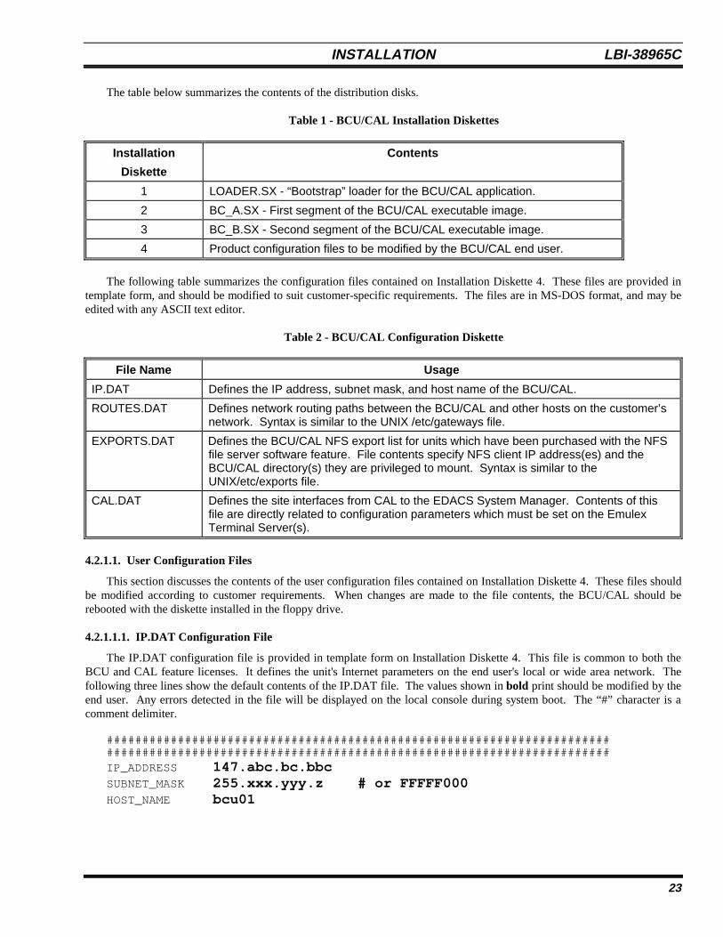
The table below summarizes the contents of the distribution disks.
Table 1 - BCU/CAL Installation Diskettes
Installation
Diskette
Contents
1 LOADER.SX - “Bootstrap” loader for the BCU/CAL application.
2 BC_A.SX - First segment of the BCU/CAL executable image.
3 BC_B.SX - Second segment of the BCU/CAL executable image.
4 Product configuration files to be modified by the BCU/CAL end user.
The following table summarizes the configuration files contained on Installation Diskette 4. These files are provided intemplate form, and should be modified to suit customer-specific requirements. The files are in MS-DOS format, and may beedited with any ASCII text editor.
Table 2 - BCU/CAL Configuration Diskette
File Name Usage
IP.DAT Defines the IP address, subnet mask, and host name of the BCU/CAL.
ROUTES.DAT Defines network routing paths between the BCU/CAL and other hosts on the customer’snetwork. Syntax is similar to the UNIX /etc/gateways file.
EXPORTS.DAT Defines the BCU/CAL NFS export list for units which have been purchased with the NFSfile server software feature. File contents specify NFS client IP address(es) and theBCU/CAL directory(s) they are privileged to mount. Syntax is similar to theUNIX/etc/exports file.
CAL.DAT Defines the site interfaces from CAL to the EDACS System Manager. Contents of thisfile are directly related to configuration parameters which must be set on the EmulexTerminal Server(s).
4.2.1.1. User Configuration Files
This section discusses the contents of the user configuration files contained on Installation Diskette 4. These files shouldbe modified according to customer requirements. When changes are made to the file contents, the BCU/CAL should berebooted with the diskette installed in the floppy drive.
4.2.1.1.1. IP.DAT Configuration File
The IP.DAT configuration file is provided in template form on Installation Diskette 4. This file is common to both theBCU and CAL feature licenses. It defines the unit's Internet parameters on the end user's local or wide area network. Thefollowing three lines show the default contents of the IP.DAT file. The values shown in bold print should be modified by theend user. Any errors detected in the file will be displayed on the local console during system boot. The “#” character is acomment delimiter.
##############################################################################################################################################IP_ADDRESS 147.abc.bc.bbcSUBNET_MASK 255.xxx.yyy.z # or FFFFF000HOST_NAME bcu01
LBI-38965C INSTALLATION
24
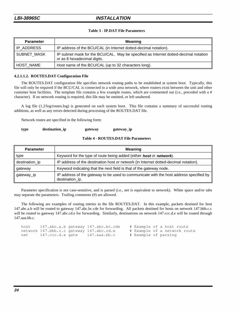
Table 3 - IP.DAT File Parameters
Parameter Meaning
IP_ADDRESS IP address of the BCU/CAL (in Internet dotted-decimal notation).
SUBNET_MASK IP subnet mask for the BCU/CAL. May be specified as Internet dotted-decimal notationor as 8 hexadecimal digits.
HOST_NAME Host name of the BCU/CAL (up to 32 characters long).
4.2.1.1.2. ROUTES.DAT Configuration File
The ROUTES.DAT configuration file specifies network routing paths to be established at system boot. Typically, thisfile will only be required if the BCU/CAL is connected to a wide area network, where routers exist between the unit and othercustomer host facilities. The template file contains a few example routes, which are commented out (i.e., preceded with a #character). If no network routing is required, this file may be omitted, or left unaltered.
A log file (1.2/log/routes.log) is generated on each system boot. This file contains a summary of successful routingadditions, as well as any errors detected during processing of the ROUTES.DAT file.
Network routes are specified in the following form:
type destination_ip gateway gateway_ip
Table 4 - ROUTES.DAT File Parameters
Parameter Meaning
type Keyword for the type of route being added (either host or network ).
destination_ip IP address of the destination host or network (in Internet dotted-decimal notation).
gateway Keyword indicating that the next field is that of the gateway node.
gateway_ip IP address of the gateway to be used to communicate with the host address specified bydestination_ip.
Parameter specification is not case-sensitive, and is parsed (i.e., net is equivalent to network). White space and/or tabsmay separate the parameters. Trailing comments (#) are allowed.
The following are examples of routing entries in the file ROUTES.DAT. In this example, packets destined for host147.abc.a.b will be routed to gateway 147.abc.bc.cde for forwarding. All packets destined for hosts on network 147.bbb.c.cwill be routed to gateway 147.abc.cd.e for forwarding. Similarly, destinations on network 147.ccc.d.e will be routed through147.aaa.bb.c.
host 147.abc.a.b gateway 147.abc.bc.cde # Example of a host routenetwork 147.bbb.c.c gateway 147.abc.cd.e # Example of a network routenet 147.ccc.d.e gate 147.aaa.bb.c # Example of parsing
INSTALLATION LBI-38965C
25
Configuration Tips
Network routes should be entered in a logical order. That is, if there are multiple gateways between the BCU/CAL and adestination, the most direct route(s) should be specified first.
Network routes may be manually added and deleted using the route command discussed in the User Interface Manual(LBI-38967). If you are unsure of proper routing, use the route command to experimentally determine the proper, or mostefficient, parameters and then add these to the ROUTES.DAT file.
Proper routing is intimately related to the IP address and subnet mask specified in the IP.DAT configuration file. Keepthese parameters in mind when adjusting ROUTES.DAT contents.
4.2.1.1.3. EXPORTS.DAT Configuration File
The EXPORTS.DAT file only applies to BCU/CAL units which have been purchased with the NFS software feature.The NFS feature is always provided with the BCU. It is an option for the CAL. BCU users may disable the NFS by using theproduct command discussed in LBI-38967.
EXPORTS.DAT defines which network clients are privileged to mount the BCU/CAL system disk. Example exportsprovided on the template disk are commented out (i.e., preceded with a # character), and thus have no effect when the file isprocessed.
A log file (1.2/log/nfs.log) is generated on each system boot. The log summarizes the processing of this file, indicatingwhat has been exported, who received the export, and any errors encountered in processing the EXPORTS.DAT file.
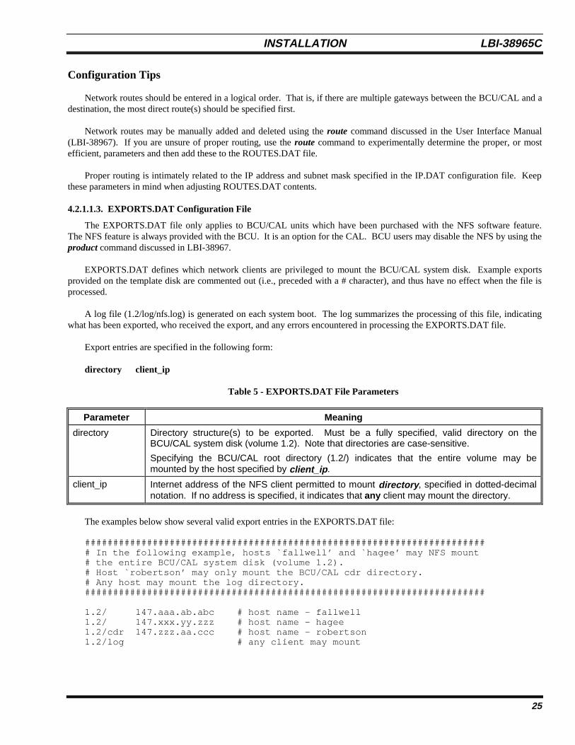
Export entries are specified in the following form:
directory client_ip
Table 5 - EXPORTS.DAT File Parameters
Parameter Meaning
directory Directory structure(s) to be exported. Must be a fully specified, valid directory on theBCU/CAL system disk (volume 1.2). Note that directories are case-sensitive.
Specifying the BCU/CAL root directory (1.2/) indicates that the entire volume may bemounted by the host specified by client_ip .
client_ip Internet address of the NFS client permitted to mount directory , specified in dotted-decimalnotation. If no address is specified, it indicates that any client may mount the directory.
The examples below show several valid export entries in the EXPORTS.DAT file:
######################################################################## In the following example, hosts `fallwell’ and `hagee’ may NFS mount# the entire BCU/CAL system disk (volume 1.2).# Host `robertson’ may only mount the BCU/CAL cdr directory.# Any host may mount the log directory.#######################################################################
1.2/ 147.aaa.ab.abc # host name - fallwell1.2/ 147.xxx.yy.zzz # host name - hagee1.2/cdr 147.zzz.aa.ccc # host name - robertson1.2/log # any client may mount
LBI-38965C INSTALLATION
26
4.2.1.1.4. CAL.DAT Configuration File
The CAL.DAT is a mandatory file for execution of the CAL software feature. It defines the interface parameters betweenthe BCU/CAL and the System Manager. The template file defines 32 example sites, which are commented out (i.e., precededwith a # character) and thus have no effect when the file is processed. Entries must be provided for each site interface theCAL will be supporting. The information contained in the CAL.DAT file must also be used to properly configure the EmulexTerminal Server(s). Terminal server configuration is discussed in detail in a separate section of this document.
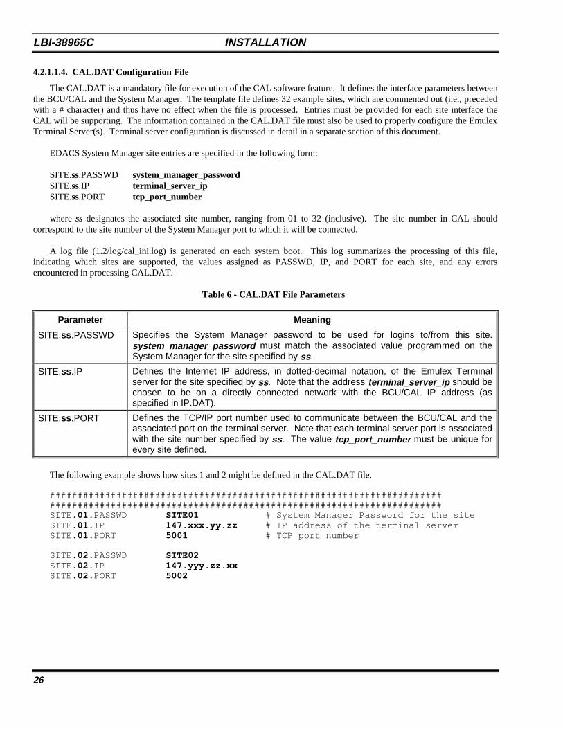
EDACS System Manager site entries are specified in the following form:
SITE.ss.PASSWD system_manager_passwordSITE.ss.IP terminal_server_ipSITE.ss.PORT tcp_port_number
where ss designates the associated site number, ranging from 01 to 32 (inclusive). The site number in CAL shouldcorrespond to the site number of the System Manager port to which it will be connected.
A log file (1.2/log/cal_ini.log) is generated on each system boot. This log summarizes the processing of this file,indicating which sites are supported, the values assigned as PASSWD, IP, and PORT for each site, and any errorsencountered in processing CAL.DAT.
Table 6 - CAL.DAT File Parameters
Parameter Meaning
SITE.ss .PASSWD Specifies the System Manager password to be used for logins to/from this site.system_manager_password must match the associated value programmed on theSystem Manager for the site specified by ss .
SITE.ss .IP Defines the Internet IP address, in dotted-decimal notation, of the Emulex Terminalserver for the site specified by ss . Note that the address terminal_server_ip should bechosen to be on a directly connected network with the BCU/CAL IP address (asspecified in IP.DAT).
SITE.ss .PORT Defines the TCP/IP port number used to communicate between the BCU/CAL and theassociated port on the terminal server. Note that each terminal server port is associatedwith the site number specified by ss . The value tcp_port_number must be unique forevery site defined.
The following example shows how sites 1 and 2 might be defined in the CAL.DAT file.
##############################################################################################################################################SITE. 01 .PASSWD SITE01 # System Manager Password for the siteSITE. 01 .IP 147.xxx.yy.zz # IP address of the terminal serverSITE. 01 .PORT 5001 # TCP port number
SITE. 02 .PASSWD SITE02SITE. 02 .IP 147.yyy.zz.xxSITE. 02 .PORT 5002
INSTALLATION LBI-38965C
27
Configuration Tips
The TCP port number selection can be of significance if the BCU/CAL is attached to a large or TCP protocol intensivenetwork. If you are unsure of TCP port usage on your network, consult you network administrator prior to assigning thesevalues. In general, beginning TCP port definition at 5000 is safe for most applications. A convenient rule of thumb is to startat 5000, with the lower digits of the port reflecting the associated site number. For example, use TCP port number 5010 forsite 10.
The parameters defined in CAL.DAT must be known when the Emulex terminal servers are to be configured. Have ahard copy of this file available when you are ready to set up the terminal servers.
The System Manager must be properly configured to recognize the sites that the BCU/CAL is simulating. Be sure thatthese sites have been defined and the passwords are correct prior to connection establishment attempts between the SystemManager and the BCU/CAL.
4.2.2. Initial Installation
The following section discusses software installation on a new BCU/CAL. An example of the expected terminal displayduring this sequence is also provided. This example is annotated with comments indicating user activity/procedures duringthe installation, as well as general information regarding the process.
PREREQUISITES
1. Verify that the BCU/CAL unit does not have power currently applied.
2. Verify that the BCU/CAL is correctly connected to a VT100-compatible terminal (user console), the IMC CAM, andthe local area network (LAN) (if applicable).
3. Verify that the user console is configured as follows:
a. 9600 baud, 1 start bit, 1 stop bit, no parity.b. VT100 personality. Terminal is DTE.c. No translation of CR to CR/LF.d. Local echo off. Tab stop at 8 characters.e. DCE/DTE handshaking off.f. XON/XOFF flow control is optional. The BCU/CAL does support flow control.
4. Edit the user configuration files contained on Installation Diskette 4.
a. Edit the text file, IP.DAT, to define the unit’s Internet parameters on the local network. If the unit will not havea network connection, the file IP.DAT may be left unmodified from that supplied with the release distribution.
b. If initial routing entries are desired, edit the file ROUTES.DAT.
c. If the NFS feature is purchased, edit EXPORTS.DAT. It is a template file for configuring NFS clients of theBCU/CAL. Client entries are specified as a BCU/CAL system disk directory, followed by the IP address of theclient permitted to mount it. A log file (1.2/log/nfs.log) is generated on each system boot. The log summarizesprocessing of this file, indicating what has been exported, who received the export, and any errors encounteredin this file. This file is processed during the application loading (boot) phase only. Modifications made after theunit is up and running will take effect during the next system boot.
LBI-38965C INSTALLATION
28
d. If the BCU/CAL has been purchased with the CAL software feature, the file CAL.DAT on Installation Diskette4 must be modified. This modification should define each site interface to the System Manager for which theCAL feature is to provide service. If the unit is only licensed for the BCU feature, the file CAL.DAT may beleft unmodified from that supplied with the release distribution.
e. Reboot the BCU/CAL.
INSTALLATION
1. Insert Installation Diskette 1 into the BCU/CAL floppy disk drive.
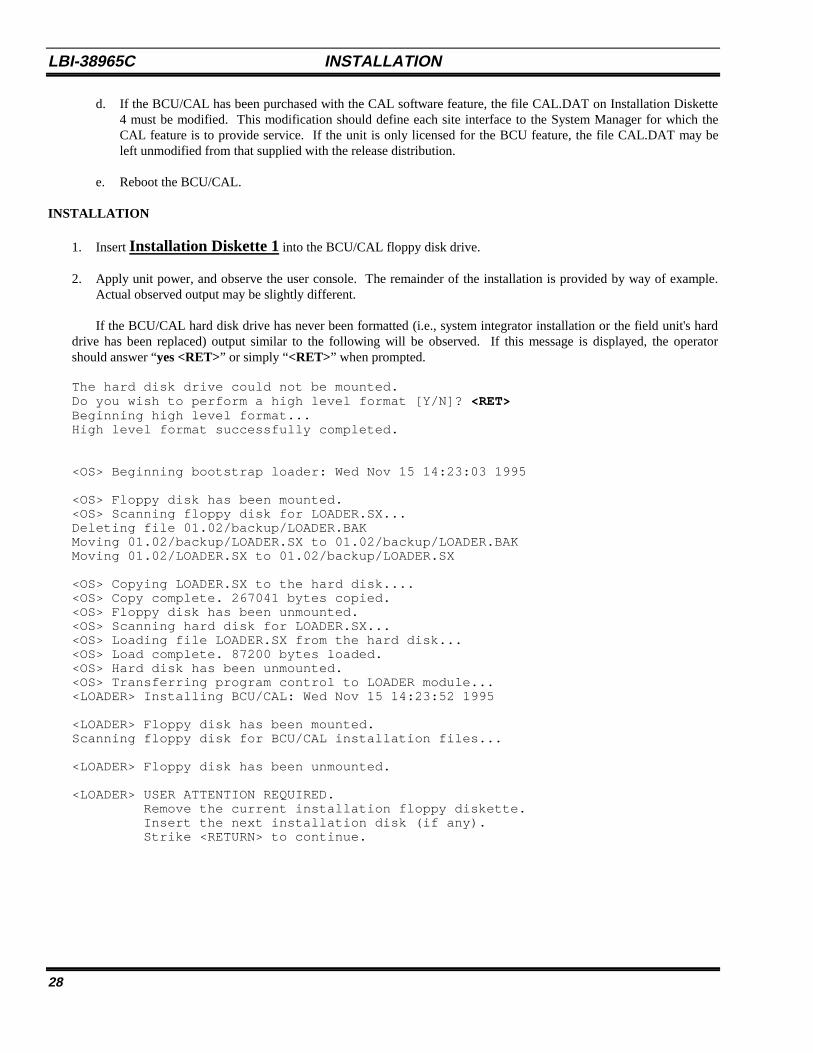
2. Apply unit power, and observe the user console. The remainder of the installation is provided by way of example.Actual observed output may be slightly different.
If the BCU/CAL hard disk drive has never been formatted (i.e., system integrator installation or the field unit's harddrive has been replaced) output similar to the following will be observed. If this message is displayed, the operatorshould answer “yes <RET>” or simply “<RET>” when prompted.
The hard disk drive could not be mounted.Do you wish to perform a high level format [Y/N]? <RET>Beginning high level format...High level format successfully completed.
<OS> Beginning bootstrap loader: Wed Nov 15 14:23:03 1995
<OS> Floppy disk has been mounted.<OS> Scanning floppy disk for LOADER.SX...Deleting file 01.02/backup/LOADER.BAKMoving 01.02/backup/LOADER.SX to 01.02/backup/LOADER.BAKMoving 01.02/LOADER.SX to 01.02/backup/LOADER.SX
<OS> Copying LOADER.SX to the hard disk....<OS> Copy complete. 267041 bytes copied.<OS> Floppy disk has been unmounted.<OS> Scanning hard disk for LOADER.SX...<OS> Loading file LOADER.SX from the hard disk...<OS> Load complete. 87200 bytes loaded.<OS> Hard disk has been unmounted.<OS> Transferring program control to LOADER module...<LOADER> Installing BCU/CAL: Wed Nov 15 14:23:52 1995
<LOADER> Floppy disk has been mounted.Scanning floppy disk for BCU/CAL installation files...
<LOADER> Floppy disk has been unmounted.
<LOADER> USER ATTENTION REQUIRED. Remove the current installation floppy diskette. Insert the next installation disk (if any). Strike <RETURN> to continue.
INSTALLATION LBI-38965C
29
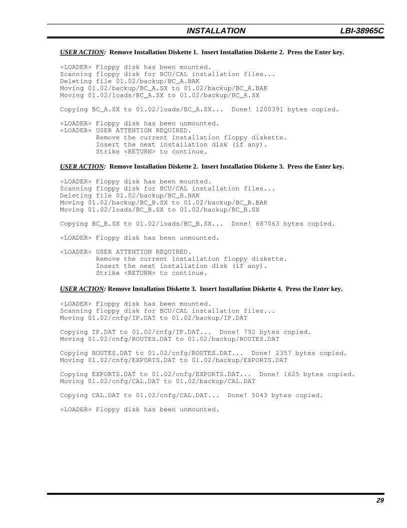
USER ACTION: Remove Installation Diskette 1. Insert Installation Diskette 2. Press the Enter key.
<LOADER> Floppy disk has been mounted.Scanning floppy disk for BCU/CAL installation files...Deleting file 01.02/backup/BC_A.BAKMoving 01.02/backup/BC_A.SX to 01.02/backup/BC_A.BAKMoving 01.02/loads/BC_A.SX to 01.02/backup/BC_A.SX
Copying BC_A.SX to 01.02/loads/BC_A.SX... Done! 1200391 bytes copied.
<LOADER> Floppy disk has been unmounted.<LOADER> USER ATTENTION REQUIRED. Remove the current installation floppy diskette. Insert the next installation disk (if any). Strike <RETURN> to continue.
USER ACTION: Remove Installation Diskette 2. Insert Installation Diskette 3. Press the Enter key.
<LOADER> Floppy disk has been mounted.Scanning floppy disk for BCU/CAL installation files...Deleting file 01.02/backup/BC_B.BAKMoving 01.02/backup/BC_B.SX to 01.02/backup/BC_B.BAKMoving 01.02/loads/BC_B.SX to 01.02/backup/BC_B.SX
Copying BC_B.SX to 01.02/loads/BC_B.SX... Done! 687063 bytes copied.
<LOADER> Floppy disk has been unmounted.
<LOADER> USER ATTENTION REQUIRED. Remove the current installation floppy diskette. Insert the next installation disk (if any). Strike <RETURN> to continue.
USER ACTION: Remove Installation Diskette 3. Insert Installation Diskette 4. Press the Enter key.
<LOADER> Floppy disk has been mounted.Scanning floppy disk for BCU/CAL installation files...Moving 01.02/cnfg/IP.DAT to 01.02/backup/IP.DAT
Copying IP.DAT to 01.02/cnfg/IP.DAT... Done! 792 bytes copied.Moving 01.02/cnfg/ROUTES.DAT to 01.02/backup/ROUTES.DAT
Copying ROUTES.DAT to 01.02/cnfg/ROUTES.DAT... Done! 2357 bytes copied.Moving 01.02/cnfg/EXPORTS.DAT to 01.02/backup/EXPORTS.DAT
Copying EXPORTS.DAT to 01.02/cnfg/EXPORTS.DAT... Done! 1625 bytes copied.Moving 01.02/cnfg/CAL.DAT to 01.02/backup/CAL.DAT
Copying CAL.DAT to 01.02/cnfg/CAL.DAT... Done! 5043 bytes copied.
<LOADER> Floppy disk has been unmounted.
LBI-38965C INSTALLATION
30
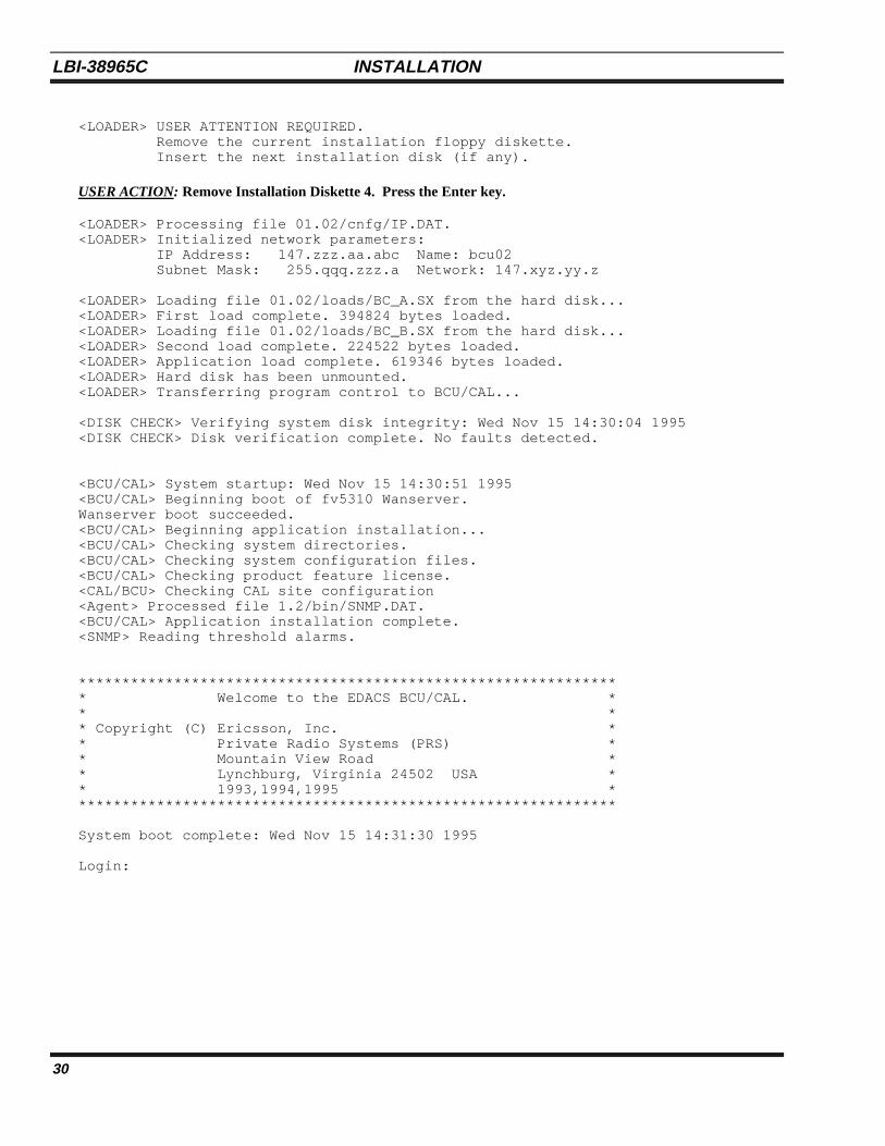
<LOADER> USER ATTENTION REQUIRED. Remove the current installation floppy diskette. Insert the next installation disk (if any).
USER ACTION: Remove Installation Diskette 4. Press the Enter key.
<LOADER> Processing file 01.02/cnfg/IP.DAT.<LOADER> Initialized network parameters: IP Address: 147.zzz.aa.abc Name: bcu02 Subnet Mask: 255.qqq.zzz.a Network: 147.xyz.yy.z
<LOADER> Loading file 01.02/loads/BC_A.SX from the hard disk...<LOADER> First load complete. 394824 bytes loaded.<LOADER> Loading file 01.02/loads/BC_B.SX from the hard disk...<LOADER> Second load complete. 224522 bytes loaded.<LOADER> Application load complete. 619346 bytes loaded.<LOADER> Hard disk has been unmounted.<LOADER> Transferring program control to BCU/CAL...
<DISK CHECK> Verifying system disk integrity: Wed Nov 15 14:30:04 1995<DISK CHECK> Disk verification complete. No faults detected.
<BCU/CAL> System startup: Wed Nov 15 14:30:51 1995<BCU/CAL> Beginning boot of fv5310 Wanserver.Wanserver boot succeeded.<BCU/CAL> Beginning application installation...<BCU/CAL> Checking system directories.<BCU/CAL> Checking system configuration files.<BCU/CAL> Checking product feature license.<CAL/BCU> Checking CAL site configuration<Agent> Processed file 1.2/bin/SNMP.DAT.<BCU/CAL> Application installation complete.<SNMP> Reading threshold alarms.
*************************************************************** Welcome to the EDACS BCU/CAL. ** ** Copyright (C) Ericsson, Inc. ** Private Radio Systems (PRS) ** Mountain View Road ** Lynchburg, Virginia 24502 USA ** 1993,1994,1995 ***************************************************************
System boot complete: Wed Nov 15 14:31:30 1995
Login:
INSTALLATION LBI-38965C
31
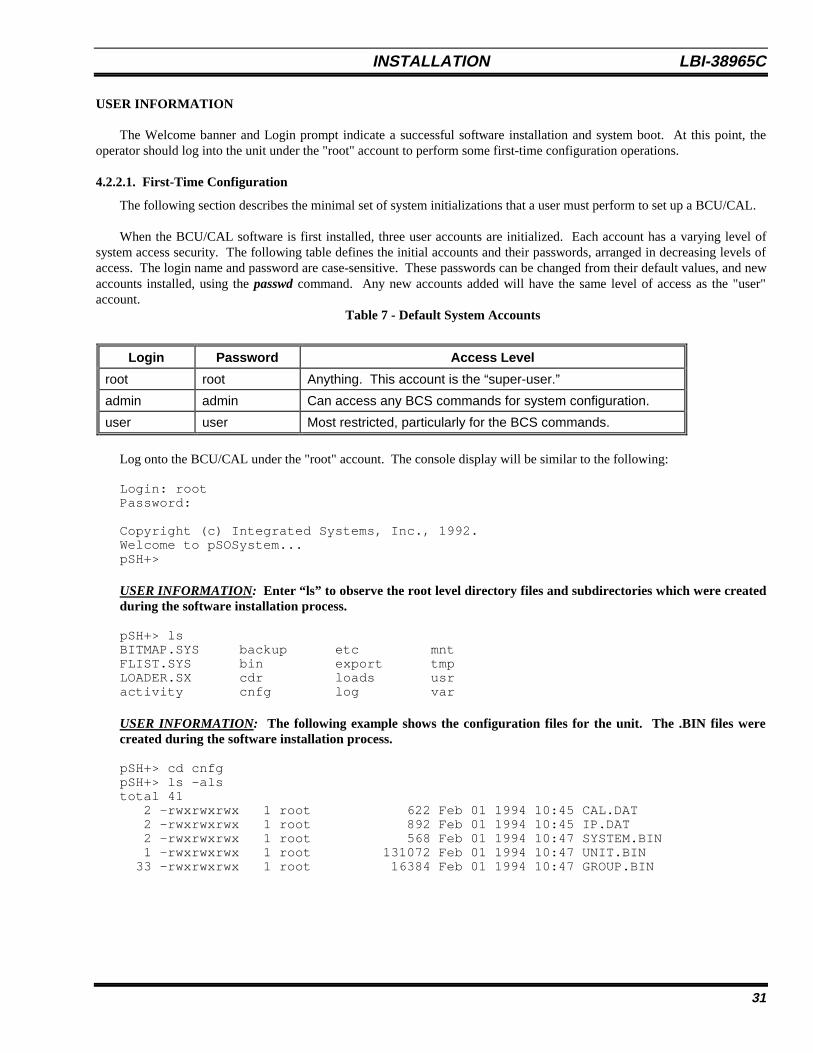
USER INFORMATION
The Welcome banner and Login prompt indicate a successful software installation and system boot. At this point, theoperator should log into the unit under the "root" account to perform some first-time configuration operations.
4.2.2.1. First-Time Configuration
The following section describes the minimal set of system initializations that a user must perform to set up a BCU/CAL.
When the BCU/CAL software is first installed, three user accounts are initialized. Each account has a varying level ofsystem access security. The following table defines the initial accounts and their passwords, arranged in decreasing levels ofaccess. The login name and password are case-sensitive. These passwords can be changed from their default values, and newaccounts installed, using the passwd command. Any new accounts added will have the same level of access as the "user"account.
Table 7 - Default System Accounts
Log onto the BCU/CAL under the "root" account. The console display will be similar to the following:
Login: rootPassword:
Copyright (c) Integrated Systems, Inc., 1992.Welcome to pSOSystem...pSH+>
USER INFORMATION: Enter “ls” to observe the root level directory files and subdirectories which were createdduring the software installation process.
pSH+> lsBITMAP.SYS backup etc mntFLIST.SYS bin export tmpLOADER.SX cdr loads usractivity cnfg log var
USER INFORMATION: The following example shows the configuration files for the unit. The .BIN files werecreated during the software installation process.
pSH+> cd cnfgpSH+> ls -alstotal 41 2 -rwxrwxrwx 1 root 622 Feb 01 1994 10:45 CAL.DAT 2 -rwxrwxrwx 1 root 892 Feb 01 1994 10:45 IP.DAT 2 -rwxrwxrwx 1 root 568 Feb 01 1994 10:47 SYSTEM.BIN 1 -rwxrwxrwx 1 root 131072 Feb 01 1994 10:47 UNIT.BIN 33 -rwxrwxrwx 1 root 16384 Feb 01 1994 10:47 GROUP.BIN
Login Password Access Level
root root Anything. This account is the “super-user.”
admin admin Can access any BCS commands for system configuration.
user user Most restricted, particularly for the BCS commands.
LBI-38965C INSTALLATION
32
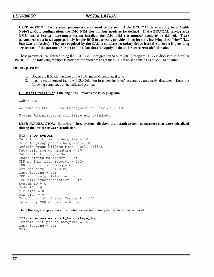
USER ACTION: Two system parameters may need to be set. If the BCU/CAL is operating in a Multi-Node/StarGate configuration, the IMC NIM slot number needs to be defined. If the BCU/CAL service area(IMC) has a Jessica interconnect system installed, the IMC PIM slot number needs to be defined. Theseparameters must be set appropriately for the BCU to correctly provide billing for calls involving these “sites” (i.e.,StarGate or Jessica). They are required by the CAL to simulate secondary drops from the site(s) it is providingservice for. If the parameter (NIM or PIM slot) does not apply, it should be set to zero (default value).
These parameters are defined using the BCU/CAL Configuration Service (BCS) program. BCS is discussed in detail inLBI-38967. The following example is provided for reference to get the BCU set up and running as quickly as possible.
PREREQUISITE
1. Obtain the IMC slot number of the NIM and PIM modules, if any.2. If not already logged into the BCU/CAL, log in under the "root" account as previously discussed. Enter the
following commands at the indicated prompts.
USER INFORMATION: Entering "bcs" invokes the BCS program.
pSH+> bcs
Welcome to the BCU-CAL Configuration Service (BCS)
System Administrator privilege acknowledged.
USER INFORMATION: Entering "show system" displays the default system parameters that were initializedduring the initial software installation.
BCS> show systemDefault unit pseudo hangtime = 10Default group pseudo hangtime = 10Default group billing mode = Bill calleeData call pseudo hangtime = 10Data call billing = OnPhone digits mandatory = OffCDR maximum file records = 1024CDR sequence wrapping = OnOffload time = 00:00:00Tape logging = OffCDR archive(s) lifetime = 7IMC time synchronization = OffSystem ID = 0Node ID = 0NIM slot = 0PIM slot = 0Telephony Call Answer Feedback = OffTelephony CDR Control = Normal
The following example shows how individual entries in the system table can be displayed.
BCS> show system /unit_hang /tape_logDefault unit pseudo hangtime = 10Tape logging = OffBCS>
INSTALLATION LBI-38965C
33
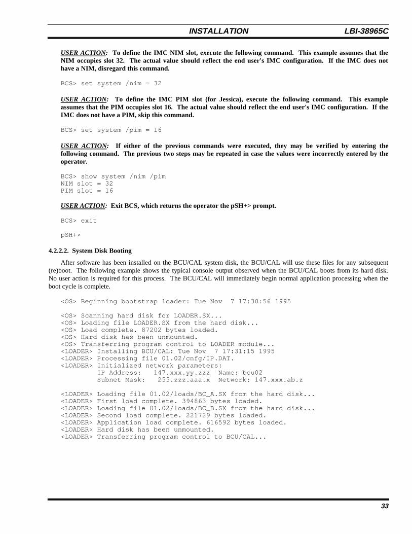
USER ACTION: To define the IMC NIM slot, execute the following command. This example assumes that theNIM occupies slot 32. The actual value should reflect the end user's IMC configuration. If the IMC does nothave a NIM, disregard this command.
BCS> set system /nim = 32
USER ACTION: To define the IMC PIM slot (for Jessica), execute the following command. This exampleassumes that the PIM occupies slot 16. The actual value should reflect the end user's IMC configuration. If theIMC does not have a PIM, skip this command.
BCS> set system /pim = 16
USER ACTION: If either of the previous commands were executed, they may be verified by entering thefollowing command. The previous two steps may be repeated in case the values were incorrectly entered by theoperator.
BCS> show system /nim /pimNIM slot = 32PIM slot = 16
USER ACTION: Exit BCS, which returns the operator the pSH+> prompt.
BCS> exit
pSH+>
4.2.2.2. System Disk Booting
After software has been installed on the BCU/CAL system disk, the BCU/CAL will use these files for any subsequent(re)boot. The following example shows the typical console output observed when the BCU/CAL boots from its hard disk.No user action is required for this process. The BCU/CAL will immediately begin normal application processing when theboot cycle is complete.
<OS> Beginning bootstrap loader: Tue Nov 7 17:30:56 1995
<OS> Scanning hard disk for LOADER.SX...<OS> Loading file LOADER.SX from the hard disk...<OS> Load complete. 87202 bytes loaded.<OS> Hard disk has been unmounted.<OS> Transferring program control to LOADER module...<LOADER> Installing BCU/CAL: Tue Nov 7 17:31:15 1995<LOADER> Processing file 01.02/cnfg/IP.DAT.<LOADER> Initialized network parameters: IP Address: 147.xxx.yy.zzz Name: bcu02 Subnet Mask: 255.zzz.aaa.x Network: 147.xxx.ab.z
<LOADER> Loading file 01.02/loads/BC_A.SX from the hard disk...<LOADER> First load complete. 394863 bytes loaded.<LOADER> Loading file 01.02/loads/BC_B.SX from the hard disk...<LOADER> Second load complete. 221729 bytes loaded.<LOADER> Application load complete. 616592 bytes loaded.<LOADER> Hard disk has been unmounted.<LOADER> Transferring program control to BCU/CAL...
LBI-38965C INSTALLATION
34
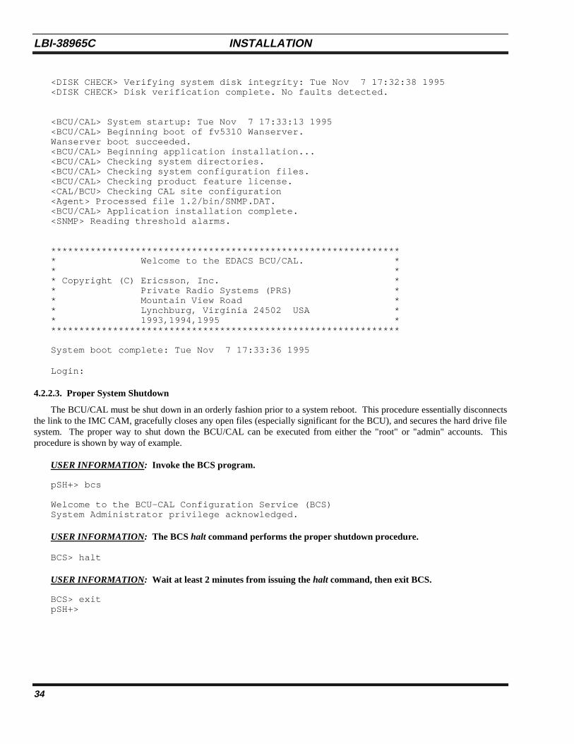
<DISK CHECK> Verifying system disk integrity: Tue Nov 7 17:32:38 1995<DISK CHECK> Disk verification complete. No faults detected.
<BCU/CAL> System startup: Tue Nov 7 17:33:13 1995<BCU/CAL> Beginning boot of fv5310 Wanserver.Wanserver boot succeeded.<BCU/CAL> Beginning application installation...<BCU/CAL> Checking system directories.<BCU/CAL> Checking system configuration files.<BCU/CAL> Checking product feature license.<CAL/BCU> Checking CAL site configuration<Agent> Processed file 1.2/bin/SNMP.DAT.<BCU/CAL> Application installation complete.<SNMP> Reading threshold alarms.
*************************************************************** Welcome to the EDACS BCU/CAL. ** ** Copyright (C) Ericsson, Inc. ** Private Radio Systems (PRS) ** Mountain View Road ** Lynchburg, Virginia 24502 USA ** 1993,1994,1995 ***************************************************************
System boot complete: Tue Nov 7 17:33:36 1995
Login:
4.2.2.3. Proper System Shutdown
The BCU/CAL must be shut down in an orderly fashion prior to a system reboot. This procedure essentially disconnectsthe link to the IMC CAM, gracefully closes any open files (especially significant for the BCU), and secures the hard drive filesystem. The proper way to shut down the BCU/CAL can be executed from either the "root" or "admin" accounts. Thisprocedure is shown by way of example.
USER INFORMATION: Invoke the BCS program.
pSH+> bcs
Welcome to the BCU-CAL Configuration Service (BCS)System Administrator privilege acknowledged.
USER INFORMATION: The BCS halt command performs the proper shutdown procedure.
BCS> halt
USER INFORMATION: Wait at least 2 minutes from issuing the halt command, then exit BCS.
BCS> exitpSH+>
INSTALLATION LBI-38965C
35
At this point, the BCU/CAL may be powered-down, or rebooted, without concern for disk data integrity. Under extreme(i.e., panic) circumstances, the "root" user can force an immediate reboot by entering reboot -h at the pSH+> prompt, either atthe user console or via a telnet connection.
4.2.3. Software Upgrades
Software upgrades are similar to the initial installation procedure discussed above. Each time the BCU/CAL boots, itwill check to determine whether a floppy diskette is installed. If a diskette is present, it will be scanned to check whether anyBCU/CAL installation files are present. If applicable files are detected, they will be copied to the appropriate system diskdirectory. As in the initial installation procedure, the operator will be prompted to remove the current diskette and insert thenext one.
This method also applies to customer modifications to the contents of Installation Diskette 4. Specifically, if (new)changes are made to either the IP.DAT or CAL.DAT files, the BCU/CAL should be rebooted with the modified disketteinserted in the floppy drive.
Note that previous software loads and user configuration files are not destroyed when an upgrade or configuration changeis installed. The BCU/CAL archives up to 3 of the last installations in the "1.2/backup" directory. These can be retrieved bythe operator in the event of problems with a new software installation, or errors in the end user modified configuration files.
4.3. CAL TERMINAL SERVER CONFIGURATION
The CAL feature of the BCU/CAL supports up to 2 Emulex P2516 Terminal Servers. Each terminal server provides 16serial ports. Of these, 15 are readily accessible for System Manager and Site Controller interfaces, with one port (port 1)being used for initial terminal server configuration.
Temporarily disconnect the Ethernet LAN connection from the terminal server. Connect a “dumb” VT100 compatibleterminal to port 1 of the terminal server to be configured. This corresponds to port 1 on the BCU/CAL distribution panel forthe first terminal server and port 17 for the second terminal server. The terminal should be configured for 9600 baud, 1 startbit, 1 stop bit, and no parity.
Log in to the first terminal server under the privileged account.
If you are greeted with a # prompt, first execute the following command:
# access
If the server requests a password enter <CTRL-Z>.
Server> suPassword> system
system is the default privileged account password. This can be changed later.
Set the terminal type used to configure the server.
Server>> change port 1 type VT100

LBI-38965C INSTALLATION
36
Define the IP address and subnet mask of the terminal server. The IP address, terminal_server_ip, must reflect theassociated address defined in the CAL.DAT file. The subnet mask, subnet_mask, should be the same as defined for theBCU/CAL in the IP.DAT configuration file. Note that subnet_mask should be in dotted decimal notation instead of the hexformat shown in the IP.DAT file.
Server>> define server ip terminal_server_ipServer>> define server subnet mask subnet_mask
EXAMPLE:
Server>> d efine server subnet mask 255.255.240.0
For each site defined in the CAL.DAT file, configure the associated port on the terminal server as follows:
Server>> change port port_no access remoteServer>> change port port_no type softcopyServer>> change port port_no autobaud disabledServer>> change port port_no speed 19200Server>> change service PORT_< port_no > <TCP port_no > port port_no telnet disabledServer>> change port port_no queuing disabledServer>> change port port_no flow control disabled
TCP port_no is the value defined in CAL.DAT for a particular site.
EXAMPLE:
Assume that the file CAL.DAT has the following two site entries: System Manger site 2 is connected to port 3 on thedistribution panel, and System Manager site 10 is connected to port 6 on the distribution panel.
SITE.02.PASSWD SITE02SITE.02.IP 147.xxx.ab.aa #Terminal server IP addressSITE.02.PORT 5002 #TCP port_no used for site 2
SITE.10.PASSWD SITE10SITE.10.IP 147.aaa.zz.bbSITE.10.PORT 5010 #TCP port_no used for site 10
Inserting the information below would configure the terminal server for the values shown above.
Server>> change port 3 access remoteServer>> change port 3 type softcopyServer>> change port 3 autobaud disabled Server>> change port 3 speed 19200Server>> change service PORT_3 5002 port 3 telnet disabledServer>> change port 3 queuing disabledServer>> change port 3 flow control disabled
Server>> change port 6 access remoteServer>> change port 6 type softcopyServer>> change port 6 autobaud disabledServer>> change port 6 speed 19200Server>> change service PORT_6 5010 port 6 telnet disabledServer>> change port 6 queuing disabledServer>> change port 6 flow control disabled

INSTALLATION LBI-38965C
37
After completing the configuration, reconnect the Ethernet LAN connection to the terminal server. If a second terminalserver is installed, repeat the procedure above.
Configuration Tips
If all 16 ports of a terminal server are needed for System Manager interface, first configure 15 of them using a “dumb”terminal connected to port 1. Port 1 (configuration port) may then be re-assigned to a remote port, accessible via a telnetconnection. Telnet into the terminal server on the OVERRIDE port number, and reconfigure port 1 as required. Refer to theEmulex Terminal Server user’s manual for additional information on server configuration via a telnet connection.
The up arrow on a VT100 can be used to recall commands to the terminal server, allowing the user to reissue the samecommand to each port on the server by only changing port_no.
The push button switch (marked default) on the front of the Emulex P2516 terminal server will erase all configurationinformation in the terminal server and return it to the factory default state. Do not use this switch to reset the terminal server.Cycle power or issue the “Initialize server” command from the server configuration port to restart the terminal server.
NOTE

LBI-38965C INSTALLATION
38
This page intentionally left blank

EDACS NETWORK MANAGEMENT SUPPORT LBI-38965C
39
5. EDACS NETWORK MANAGEMENT SUPPORT BY THE BCU/CAL
Refer to LBI-39171, “EDACS Network Management Installation and Technical Reference Manual,” for additionalinformation on setting up the BCU for use with the EDACS Network Manager.
5.1. NETWORK MANAGER CONFIGURATION
Ensure that the BCU/CAL contains the following settings for Network Manager connectivity.
1. Log into the BCU/CAL under the root account.
Login: root Password:
2. Enable the Ethernet Interface by setting up the IP.DAT configuration file as discussed in section 4 herein.
3. Enter the following information at the prompts:
pSH+> bcs
BCS> show system
BCS> set system/PIM = 16 (This is the SITE_ID, which ranges from 1 to 32. The default is 16.)
BCS> set system/NIM = 32 (This is the NIM Number of the IMC. This number ranges from 1 to 32.)
BCS> set system/node = 33
BCS> exit
pSH+> product -l (Ensure that the Multisite Monitor (MSM) license is enabled if the BCU/CAL isproviding Multisite Monitor/Site Monitor information. Note: A reboot isrequired to see any license change.)
3. Execute the trap command to define to which Network Manager Station the traps are sent.
For example: pSH+> trap -a -i IP Address of NM
4. Enter the comm command to define which Network Manager Station may read or write to this platform.
For example: pSH+> comm -a -i IP Address of NM -c edacs -v write
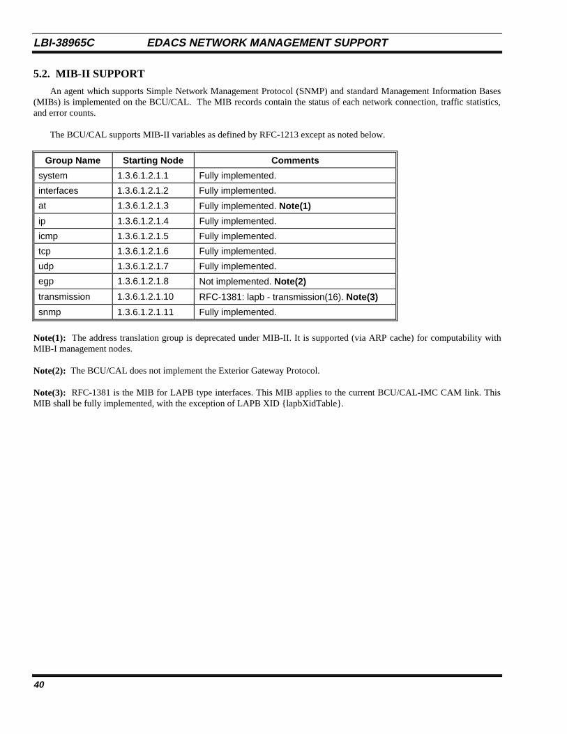
LBI-38965C EDACS NETWORK MANAGEMENT SUPPORT
40
5.2. MIB-II SUPPORT
An agent which supports Simple Network Management Protocol (SNMP) and standard Management Information Bases(MIBs) is implemented on the BCU/CAL. The MIB records contain the status of each network connection, traffic statistics,and error counts.
The BCU/CAL supports MIB-II variables as defined by RFC-1213 except as noted below.
Group Name Starting Node Comments
system 1.3.6.1.2.1.1 Fully implemented.
interfaces 1.3.6.1.2.1.2 Fully implemented.
at 1.3.6.1.2.1.3 Fully implemented. Note(1)
ip 1.3.6.1.2.1.4 Fully implemented.
icmp 1.3.6.1.2.1.5 Fully implemented.
tcp 1.3.6.1.2.1.6 Fully implemented.
udp 1.3.6.1.2.1.7 Fully implemented.
egp 1.3.6.1.2.1.8 Not implemented. Note(2)
transmission 1.3.6.1.2.1.10 RFC-1381: lapb - transmission(16). Note(3)
snmp 1.3.6.1.2.1.11 Fully implemented.
Note(1): The address translation group is deprecated under MIB-II. It is supported (via ARP cache) for computability withMIB-I management nodes.
Note(2): The BCU/CAL does not implement the Exterior Gateway Protocol.
Note(3): RFC-1381 is the MIB for LAPB type interfaces. This MIB applies to the current BCU/CAL-IMC CAM link. ThisMIB shall be fully implemented, with the exception of LAPB XID {lapbXidTable}.
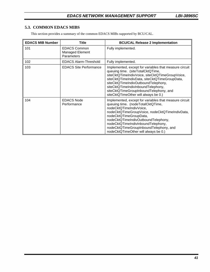
EDACS NETWORK MANAGEMENT SUPPORT LBI-38965C
41
5.3. COMMON EDACS MIBS
This section provides a summary of the common EDACS MIBs supported by BCU/CAL.
EDACS MIB Number Title BCU/CAL Release 2 Implementation
101 EDACS CommonManaged ElementParameters
Fully implemented.
102 EDACS Alarm-Threshold Fully implemented.
103 EDACS Site Performance Implemented, except for variables that measure circuitqueuing time. (siteTotalCktQTime,siteCktQTimeIndivVoice, siteCktQTimeGroupVoice,siteCktQTimeIndivData, siteCktQTimeGroupData,siteCktQTimeIndivOutboundTelephony,siteCktQTimeIndivInboundTelephony,siteCktQTimeGroupInboundTelephony, andsiteCktQTimeOther will always be 0.)
104 EDACS NodePerformance
Implemented, except for variables that measure circuitqueuing time. (nodeTotalCktQTime,nodeCktQTimeIndivVoice,nodeCktQTimeGroupVoice, nodeCktQTimeIndivData,nodeCktQTimeGroupData,nodeCktQTimeIndivOutboundTelephony,nodeCktQTimeIndivInboundTelephony,nodeCktQTimeGroupInboundTelephony, andnodeCktQTimeOther will always be 0.)
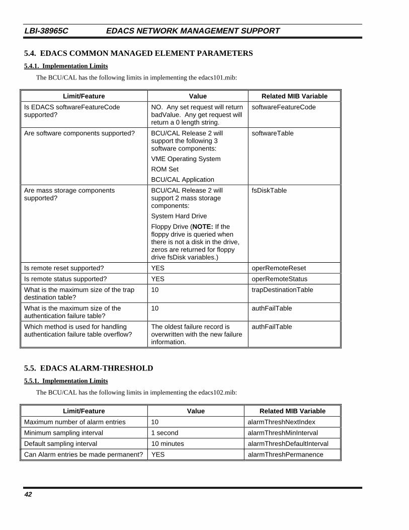
LBI-38965C EDACS NETWORK MANAGEMENT SUPPORT
42
5.4. EDACS COMMON MANAGED ELEMENT PARAMETERS
5.4.1. Implementation Limits
The BCU/CAL has the following limits in implementing the edacs101.mib:
Limit/Feature Value Related MIB Variable
Is EDACS softwareFeatureCodesupported?
NO. Any set request will returnbadValue. Any get request willreturn a 0 length string.
softwareFeatureCode
Are software components supported? BCU/CAL Release 2 willsupport the following 3software components:
VME Operating System
ROM Set
BCU/CAL Application
softwareTable
Are mass storage componentssupported?
BCU/CAL Release 2 willsupport 2 mass storagecomponents:
System Hard Drive
Floppy Drive (NOTE: If thefloppy drive is queried whenthere is not a disk in the drive,zeros are returned for floppydrive fsDisk variables.)
fsDiskTable
Is remote reset supported? YES operRemoteReset
Is remote status supported? YES operRemoteStatus
What is the maximum size of the trapdestination table?
10 trapDestinationTable
What is the maximum size of theauthentication failure table?
10 authFailTable
Which method is used for handlingauthentication failure table overflow?
The oldest failure record isoverwritten with the new failureinformation.
authFailTable
5.5. EDACS ALARM-THRESHOLD
5.5.1. Implementation Limits
The BCU/CAL has the following limits in implementing the edacs102.mib:
Limit/Feature Value Related MIB Variable
Maximum number of alarm entries 10 alarmThreshNextIndex
Minimum sampling interval 1 second alarmThreshMinInterval
Default sampling interval 10 minutes alarmThreshDefaultInterval
Can Alarm entries be made permanent? YES alarmThreshPermanence

EDACS NETWORK MANAGEMENT SUPPORT LBI-38965C
43
5.5.2. Default Threshold Alarms
By default, BCU/CAL Release 2 will have the threshold alarms listed in the table below. Since threshold alarm settingscan be saved on disk, these defaults will only be set on initial installation or if the alarm file is deleted.
Variable SampleType
StartupAlarm
RisingThreshold
FallingThreshold
SamplingInterval
fsDiskPercentBlocksUsed
[From edacs101.mib]
absoluteValue(1)
rising
Alarm(2)
90 70 1 hr
fsDiskPercentInodesUsed
[From edacs101.mib]
absoluteValue(1)
rising
Alarm(2)
90 70 1 hr
5.6. EDACS SITE PERFORMANCE
BCU/CAL Release 2 will not support the Circuit Queuing parameters from the edacs103.mib for the BCU/CAL Site (asdefined by the configuration parameter SITE_ID).
5.7. SNMP TRAP SUMMARY
This section lists all SNMP Traps that the BCU/CAL can generate.
5.7.1. Generic Traps
The following are the generic traps as specified in RFC-1215 (see LBI-39169, EDACS Network Manager User’sManual).
Trap Description MIB VariablesIncluded
Controls
coldStart Signifies that the BCU/CAL isreinitializing itself.
NONE Always enabled
warmStart Signifies that the BCU/CAL isreinitializing itself without changingagent configuration.
NONE Always enabled
linkDown Signifies that a link has failed. Thefollowing links are supported:
BCU/CAL-IMC Control link
ifIndex Always enabled
linkUp Signifies that a link has come up.The following links are supported:
BCU/CAL-IMC Control link
ifIndex Always enabled
authenticationFailure Signifies that an SNMP messagewas not properly authenticated.
NONE snmpEnableAuthen-
Traps
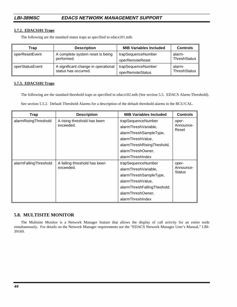
LBI-38965C EDACS NETWORK MANAGEMENT SUPPORT
44
5.7.2. EDACS101 Traps
The following are the standard status traps as specified in edacs101.mib.
Trap Description MIB Variables Included Controls
operResetEvent A complete system reset is beingperformed.
trapSequenceNumber
operRemoteReset
alarm-ThreshStatus
operStatusEvent A significant change in operationalstatus has occurred.
trapSequenceNumber
operRemoteStatus
alarm-ThreshStatus
5.7.3. EDACS102 Traps
The following are the standard threshold traps as specified in edacs102.mib (See section 5.5. EDACS Alarm-Threshold).
See section 5.5.2. Default Threshold Alarms for a description of the default threshold alarms in the BCU/CAL.
Trap Description MIB Variables Included Controls
alarmRisingThreshold A rising threshold has beenexceeded.
trapSequenceNumber
alarmThreshVariable,
alarmThreshSampleType,
alarmThreshValue,
alarmThreshRisingTheshold,
alarmThreshOwner,
alarmThreshIndex
oper-Announce-Reset
alarmFallingThreshold A falling threshold has beenexceeded.
trapSequenceNumber
alarmThreshVariable,
alarmThreshSampleType,
alarmThreshValue,
alarmThreshFallingTheshold,
alarmThreshOwner,
alarmThreshIndex
oper-Announce-Status
5.8. MULTISITE MONITOR
The Multisite Monitor is a Network Manager feature that allows the display of call activity for an entire nodesimultaneously. For details on the Network Manager requirements see the “EDACS Network Manager User’s Manual,” LBI-39169.
EDACS NETWORK MANAGEMENT SUPPORT LBI-38965C
45
5.9. SECURITY MANAGEMENT
The BCU/CAL only supports trivial authentication procedures as delineated under the SNMP group of RFC-1213.
• The BCU/CAL supports a unique community name for all SNMP get, set, and trap operations. The maximum lengthof each community name is 32 ASCII characters. The community names are maintained in non-volatile storage.
• The community name is part of the BCU/CAL configuration data, and access to the community name is restricted tothe super-user (root) account.
• The BCU/CAL supports the ability to generate authentication failure notification to the Network Managementstations(s) for operations attempted with an invalid community name.
In order to support the Network Manager Security Management on the BCU/CAL product, two new user interfacecommands were implemented. These commands, comm and trap, are described in detail in the “EDACS BCU/CAL UserInterface Manual,” LBI-38967.
The comm command allows the root user to view, add an entry to, delete an entry from, or modify an entry in theSNMPv1 Get-Set Community Profile Table. The table contains a specific machine’s IP address, get-set community name,and MIB view.
The trap command allows the root user to view, add an entry to, or delete an entry from, the SNMPv1 Trap Table. Thetable contains IP addresses to which the traps will be sent. The trap community name is always “edacs.”

LBI-38965C EDACS NETWORK MANAGEMENT SUPPORT
46
This page intentionally left blank

EDACS BILLING FORMAT LBI-38965C
A-1
APPENDIX AEDACS BILLING (CDR) FORMAT
LBI-38965C EDACS BILLING FORMAT
A-2
This appendix defines the EDACS call detail record (CDR) format for the collection of system resource usage data in amultisite trunked radio system. The document is intended for use primarily by air time billing software developers who usethis record format as input, as well as for developers of equipment and software to collect and archive call detail data fromEDACS.
1. OVERVIEWThe EDACS CDR is designed to record call activity on an EDACS multisite trunked radio system. The records are
intended primarily for billing purposes. The EDACS CDR format balances efficient storage with comprehensive resourceutilization data.
2. BILLING BY CONVERSATIONEDACS uses transmission trunking to allocate RF channels. Unlike a landline telephone conversation, where a single
circuit is established at the beginning of the call and disconnected at the end, EDACS establishes a new "circuit" (assigns anRF channel) each time a conversation participant presses the PTT switch on a radio, and disconnects (drops the channel) assoon as the PTT switch is released. Thus, a single conversation may result in several RF channel assignments. Rather thandesignate each of these brief transmissions as a call requiring its own CDR, the EDACS CDR format permits all of thetransmissions making up a single conversation to be recorded in a single CDR. The CDR records the elapsed time of theconversation, the actual accumulated air time (time that an RF channel was in use) and the number of transmissions involved.A list of the channels used in the call is also part of the record.
3. BILLING FOR MULTIPLE SITESEDACS allows calls which originate on one radio site and use RF channels on one or more additional sites. The EDACS
CDR format accommodates these calls by recording the site number and a list of the RF channels used for each siteparticipating in the call. In addition , the accumulated air time field in the CDR contains the total air time used on all sites. Inthis case, the accumulated air time value will usually be greater than the elapsed time.
4. RECORD ENCODINGAn EDACS CDR is an ASCII text record terminated by a linefeed character (LF, decimal 10). The record consists of
fixed length fields. The total number of fields in the record is variable, depending on whether the call involved multiple sitesor was a radio-originated telephone interconnect call.
Most of the fields are numeric data and are specified as either Decimal or Hex format. Decimal format fields are radix-10 integers encoded using the ASCII characters from decimal 48 (“0”) through decimal 57 (“9”). Hex fields are radix-16integers encoded using the ASCII characters from decimal 48 (“0”) through decimal 57 (“9”) and decimal 65 (“A”) throughdecimal 70 (“F”). Two additional formats are used. The radix-64 format is used to provide a sequence number for eachrecord. The last format used is the dialed digits format. This format is used to record a telephone number dialed by theoriginator of a mobile-to-land telephone interconnect call. The standard digits on a telephone DTMF keypad are encodedusing the ASCII characters decimal 35 (“#”), decimal 42 (“*”), and decimal 48 (“0”) through decimal 57 (“9”).
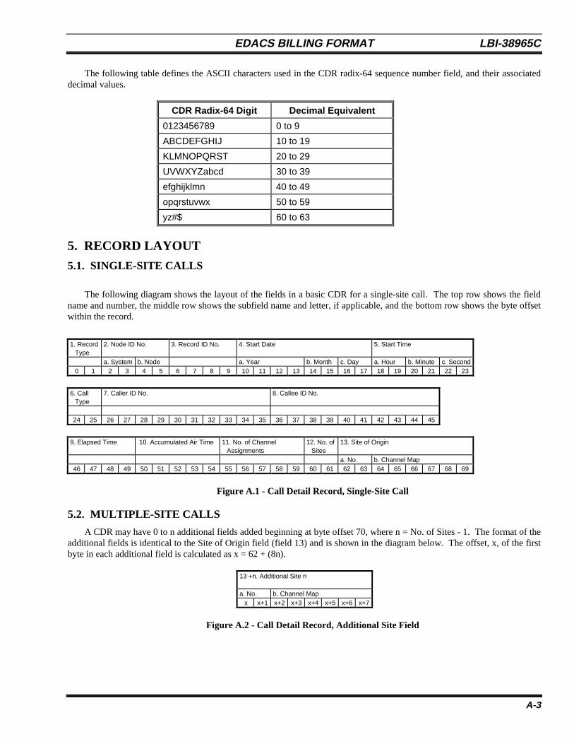
EDACS BILLING FORMAT LBI-38965C
A-3
The following table defines the ASCII characters used in the CDR radix-64 sequence number field, and their associateddecimal values.
CDR Radix-64 Digit Decimal Equivalent
0123456789 0 to 9
ABCDEFGHIJ 10 to 19
KLMNOPQRST 20 to 29
UVWXYZabcd 30 to 39
efghijklmn 40 to 49
opqrstuvwx 50 to 59
yz#$ 60 to 63
5. RECORD LAYOUT
5.1. SINGLE-SITE CALLS
The following diagram shows the layout of the fields in a basic CDR for a single-site call. The top row shows the fieldname and number, the middle row shows the subfield name and letter, if applicable, and the bottom row shows the byte offsetwithin the record.
1. RecordType
2. Node ID No. 3. Record ID No. 4. Start Date 5. Start Time
a. System b. Node a. Year b. Month c. Day a. Hour b. Minute c. Second0 1 2 3 4 5 6 7 8 9 10 11 12 13 14 15 16 17 18 19 20 21 22 23
6. CallType
7. Caller ID No. 8. Callee ID No.
24 25 26 27 28 29 30 31 32 33 34 35 36 37 38 39 40 41 42 43 44 45
9. Elapsed Time 10. Accumulated Air Time 11. No. of ChannelAssignments
12. No. ofSites
13. Site of Origin
a. No. b. Channel Map46 47 48 49 50 51 52 53 54 55 56 57 58 59 60 61 62 63 64 65 66 67 68 69
Figure A.1 - Call Detail Record, Single-Site Call
5.2. MULTIPLE-SITE CALLS
A CDR may have 0 to n additional fields added beginning at byte offset 70, where n = No. of Sites - 1. The format of theadditional fields is identical to the Site of Origin field (field 13) and is shown in the diagram below. The offset, x, of the firstbyte in each additional field is calculated as x = 62 + (8n).
Figure A.2 - Call Detail Record, Additional Site Field
13 +n. Additional Site n
a. No. b. Channel Mapx x+1 x+2 x+3 x+4 x+5 x+6 x+7

LBI-38965C EDACS BILLING FORMAT
A-4
5.3. MOBILE-TO-LAND TELEPHONE INTERCONNECT CALLS
A CDR for a mobile-to-land telephone interconnect call will have an additional field beginning at byte offset 70. Thisfield contains the digits dialed by the caller. A mobile-to-land call never involves multiple sites, so the PSTN TelephoneNumber field is never combined with the Additional Site fields described in the preceding section.
14. PSTN Telephone No.
70 71 72 73 74 75 76 77 78 79 80 81 82 83 84 85 86 87 88 89 90 91..
101
Figure A.3 - Call Detail Record, PSTN Telephone Number Field
5.4. CALCULATING THE NUMBER OF BYTES IN A CDR
Note that the final linefeed character which terminates the record is not shown in these diagrams. The actual number ofbytes in a CDR is calculated by adding 2 to the offset of the final byte. For example, a group call involving 4 sites contains 3additional site fields, beginning at offset 70 and ending at offset 93 (from the formulae above). The actual length of therecord, including the linefeed character, is thus 95 bytes.
5.5. CDR FIELD DESCRIPTIONS
Table A.1 contains detailed descriptions of each of the CDR fields.
Table A.1 - Call Detail Record Field Descriptions
No. Name Size Format Range/Values Description
1. Record Type 2 Hex 00 - FF Defines the type of record.00 = Mobile to Mobile01 = Mobile to Land Interconnect02 = Illegal03 = Land to Mobile Interconnect04 = Data05- FF = Reserved
2.
a.b.
Node ID No.
SystemNode
4
22
HexHex
00 - FF00 - FF
Unique identification number for the EDACS node where the callactivity in this CDR occurred. User configurable.
System ID Number (Multiple nodes)Node ID Number (Multiple sites)
3. Record ID No. 4 Radix-64 Unique identifier for the Call Detail Record.4.
a.b.c.
Start DateYearMonthDay
8422
DecimalDecimalDecimal
1970-203801 - 1201 - 31
The date when the call was initiated.
5.a.b.c.
Start TimeHourMinuteSecond
6222
DecimalDecimalDecimal
00 - 2300 - 5900 - 59
The time of day when the call was initiated. Hours are in militaryformat.
6. Call Type 2 Hex 00 - FF (SeeTable A.2)
The type of call as defined in Table A.2. Indicates whether call isgroup or individual, whether to bill the caller or the callee, etc.
7. Caller ID No. 10 Decimal 0000000000 -9999999999
For Record Types 00 and 01, this field contains the Logical ID (LID)of the caller. For Record Type 03, the field contains theInterconnect Line number.
8. Callee ID No. 10 Decimal 0000000000 -9999999999
For Record Types 00 and 03, this field contains the Logical ID (LID)of an individual callee, or the Group ID (GID) of a call group. (TheCall Type field indicates individual or group call.) For Record Type01, the field contains the Interconnect Line number.
9. Elapsed Time 4 Hex 0000 - FFFF The duration of the call in seconds10. Accumulated Air
Time5 Hex 00000 - FFFFF The number of seconds of actual air time used on all sites on the
local node for this call. Does not include air time on site 32 which isa remote node.
11. No. of ChannelAssignments
5 Hex 00000 - FFFFF The number of times a channel assignment occurred on a site withinthe local node for this call.
12. Number of Sites 2 Decimal 01 - 32 The number of sites on the local node which participated in this call.
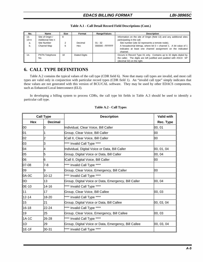
EDACS BILLING FORMAT LBI-38965C
A-5
Table A.1 - Call Detail Record Field Descriptions (Cont.)
No. Name Size Format Range/Values Description13.13+n
a.b.
Site of Origin /Additional Site nSite NumberChannel Map
8
26
DecimalHex
01 - 32000000 - FFFFFF
Information on the site of Origin (field 13) and any additional sitesparticipating in the call.
Site number (site 32 represents a remote node).A hexadecimal bitmap, where bit 0 = channel 1. A bit value of 1indicates at least one channel assignment on the indicatedchannel.
14. PSTN TelephoneNo.
32 Dialed Digits Occurs in Record Type 01 only. Contains up to 32 digits dialed bythe caller. The digits are left justified and padded with ASCII SP(decimal 32) on the right.
6. CALL TYPE DEFINITIONSTable A.2 contains the typical values of the call type (CDR field 6). Note that many call types are invalid, and most call
types are valid only in conjunction with particular record types (CDR field 1). An “invalid call type” simply indicates thatthese values are not generated with this version of BCU/CAL software. They may be used by other EDACS components,such as Enhanced Local Interconnect (ELI).
In developing a billing system to process CDRs, the call type bit fields in Table A.3 should be used to identify aparticular call type.
Table A.2 - Call Types
Call Type Description Valid with
Hex Decimal Rec. Type
00 0 Individual, Clear Voice, Bill Caller 00, 01
01 1 Group, Clear Voice, Bill Caller 00
02 2 ICall II, Clear Voice, Bill Caller 00
03 3 **** Invalid Call Type ****
04 4 Individual, Digital Voice or Data, Bill Caller 00, 01, 04
05 5 Group, Digital Voice or Data, Bill Caller 00, 04
06 6 ICall II, Digital Voice, Bill Caller 00
07-08 7-8 **** Invalid Call Type ****
09 9 Group, Clear Voice, Emergency, Bill Caller 00
0A-0C 10-12 **** Invalid Call Type ****
0D 13 Group, Digital Voice or Data, Emergency, Bill Caller 00, 04
0E-10 14-16 **** Invalid Call Type ****
11 17 Group, Clear Voice, Bill Callee 00, 03
12-14 18-20 **** Invalid Call Type ****
15 21 Group, Digital Voice or Data, Bill Callee 00, 03, 04
16-18 22-24 **** Invalid Call Type ****
19 25 Group, Clear Voice, Emergency, Bill Callee 00, 03
1A-1C 26-28 **** Invalid Call Type ****
1D 29 Group, Digital Voice or Data, Emergency, Bill Callee 00, 03, 04
1E-1F 30-31 **** Invalid Call Type ****
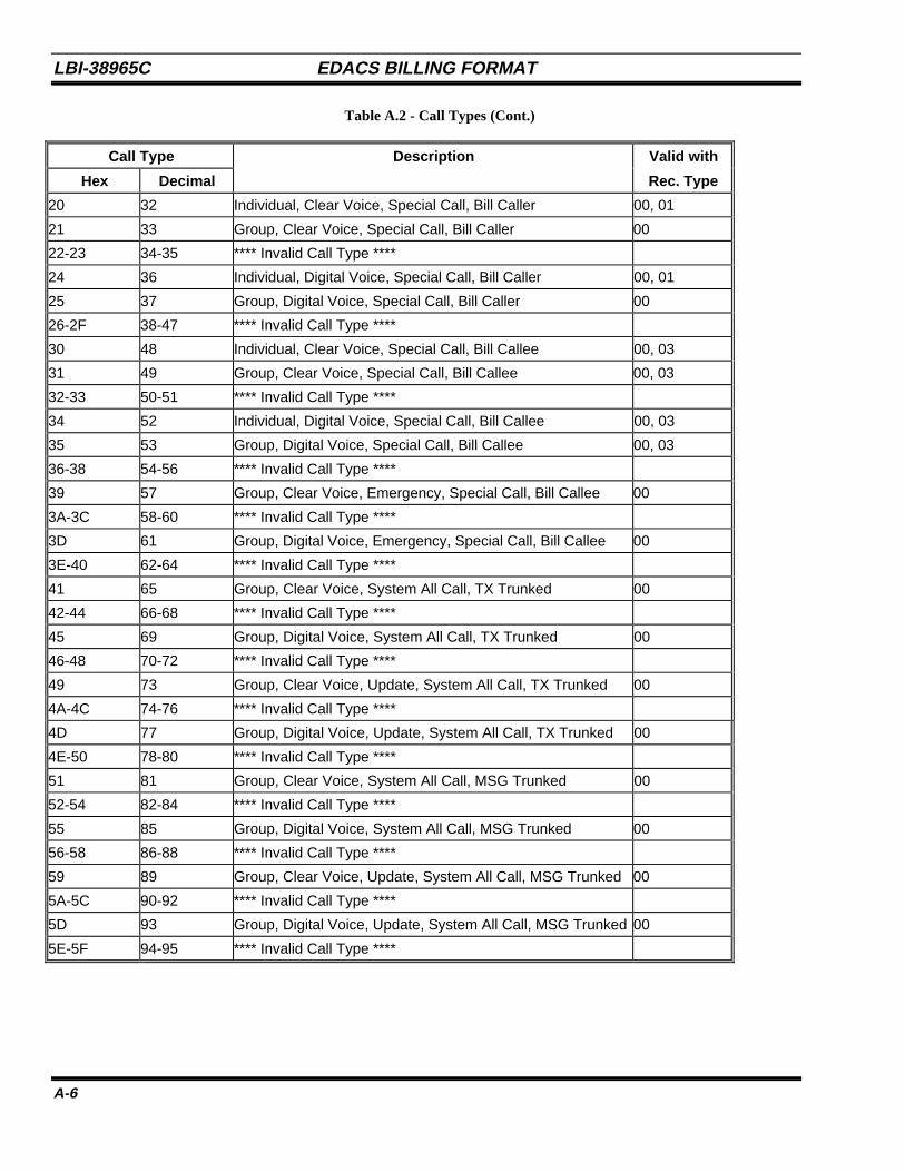
LBI-38965C EDACS BILLING FORMAT
A-6
Table A.2 - Call Types (Cont.)
Call Type Description Valid with
Hex Decimal Rec. Type
20 32 Individual, Clear Voice, Special Call, Bill Caller 00, 01
21 33 Group, Clear Voice, Special Call, Bill Caller 00
22-23 34-35 **** Invalid Call Type ****
24 36 Individual, Digital Voice, Special Call, Bill Caller 00, 01
25 37 Group, Digital Voice, Special Call, Bill Caller 00
26-2F 38-47 **** Invalid Call Type ****
30 48 Individual, Clear Voice, Special Call, Bill Callee 00, 03
31 49 Group, Clear Voice, Special Call, Bill Callee 00, 03
32-33 50-51 **** Invalid Call Type ****
34 52 Individual, Digital Voice, Special Call, Bill Callee 00, 03
35 53 Group, Digital Voice, Special Call, Bill Callee 00, 03
36-38 54-56 **** Invalid Call Type ****
39 57 Group, Clear Voice, Emergency, Special Call, Bill Callee 00
3A-3C 58-60 **** Invalid Call Type ****
3D 61 Group, Digital Voice, Emergency, Special Call, Bill Callee 00
3E-40 62-64 **** Invalid Call Type ****
41 65 Group, Clear Voice, System All Call, TX Trunked 00
42-44 66-68 **** Invalid Call Type ****
45 69 Group, Digital Voice, System All Call, TX Trunked 00
46-48 70-72 **** Invalid Call Type ****
49 73 Group, Clear Voice, Update, System All Call, TX Trunked 00
4A-4C 74-76 **** Invalid Call Type ****
4D 77 Group, Digital Voice, Update, System All Call, TX Trunked 00
4E-50 78-80 **** Invalid Call Type ****
51 81 Group, Clear Voice, System All Call, MSG Trunked 00
52-54 82-84 **** Invalid Call Type ****
55 85 Group, Digital Voice, System All Call, MSG Trunked 00
56-58 86-88 **** Invalid Call Type ****
59 89 Group, Clear Voice, Update, System All Call, MSG Trunked 00
5A-5C 90-92 **** Invalid Call Type ****
5D 93 Group, Digital Voice, Update, System All Call, MSG Trunked 00
5E-5F 94-95 **** Invalid Call Type ****
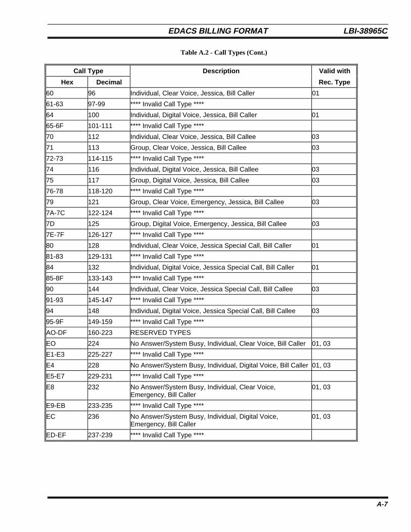
EDACS BILLING FORMAT LBI-38965C
A-7
Table A.2 - Call Types (Cont.)
Call Type Description Valid with
Hex Decimal Rec. Type
60 96 Individual, Clear Voice, Jessica, Bill Caller 01
61-63 97-99 **** Invalid Call Type ****
64 100 Individual, Digital Voice, Jessica, Bill Caller 01
65-6F 101-111 **** Invalid Call Type ****
70 112 Individual, Clear Voice, Jessica, Bill Callee 03
71 113 Group, Clear Voice, Jessica, Bill Callee 03
72-73 114-115 **** Invalid Call Type ****
74 116 Individual, Digital Voice, Jessica, Bill Callee 03
75 117 Group, Digital Voice, Jessica, Bill Callee 03
76-78 118-120 **** Invalid Call Type ****
79 121 Group, Clear Voice, Emergency, Jessica, Bill Callee 03
7A-7C 122-124 **** Invalid Call Type ****
7D 125 Group, Digital Voice, Emergency, Jessica, Bill Callee 03
7E-7F 126-127 **** Invalid Call Type ****
80 128 Individual, Clear Voice, Jessica Special Call, Bill Caller 01
81-83 129-131 **** Invalid Call Type ****
84 132 Individual, Digital Voice, Jessica Special Call, Bill Caller 01
85-8F 133-143 **** Invalid Call Type ****
90 144 Individual, Clear Voice, Jessica Special Call, Bill Callee 03
91-93 145-147 **** Invalid Call Type ****
94 148 Individual, Digital Voice, Jessica Special Call, Bill Callee 03
95-9F 149-159 **** Invalid Call Type ****
AO-DF 160-223 RESERVED TYPES
EO 224 No Answer/System Busy, Individual, Clear Voice, Bill Caller 01, 03
E1-E3 225-227 **** Invalid Call Type ****
E4 228 No Answer/System Busy, Individual, Digital Voice, Bill Caller 01, 03
E5-E7 229-231 **** Invalid Call Type ****
E8 232 No Answer/System Busy, Individual, Clear Voice,Emergency, Bill Caller
01, 03
E9-EB 233-235 **** Invalid Call Type ****
EC 236 No Answer/System Busy, Individual, Digital Voice,Emergency, Bill Caller
01, 03
ED-EF 237-239 **** Invalid Call Type ****
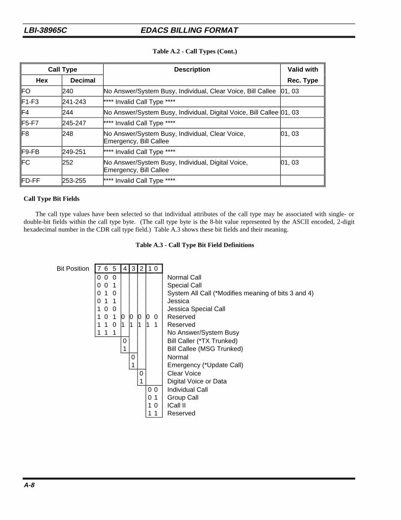
LBI-38965C EDACS BILLING FORMAT
A-8
Table A.2 - Call Types (Cont.)
Call Type Description Valid with
Hex Decimal Rec. Type
FO 240 No Answer/System Busy, Individual, Clear Voice, Bill Callee 01, 03
F1-F3 241-243 **** Invalid Call Type ****
F4 244 No Answer/System Busy, Individual, Digital Voice, Bill Callee 01, 03
F5-F7 245-247 **** Invalid Call Type ****
F8 248 No Answer/System Busy, Individual, Clear Voice,Emergency, Bill Callee
01, 03
F9-FB 249-251 **** Invalid Call Type ****
FC 252 No Answer/System Busy, Individual, Digital Voice,Emergency, Bill Callee
01, 03
FD-FF 253-255 **** Invalid Call Type ****
Call Type Bit Fields
The call type values have been selected so that individual attributes of the call type may be associated with single- ordouble-bit fields within the call type byte. (The call type byte is the 8-bit value represented by the ASCII encoded, 2-digithexadecimal number in the CDR call type field.) Table A.3 shows these bit fields and their meaning.
Table A.3 - Call Type Bit Field Definitions
Bit Position 7 6 5 4 3 2 1 0 0 0 0 Normal Call 0 0 1 Special Call 0 1 0 System All Call (*Modifies meaning of bits 3 and 4) 0 1 1 Jessica 1 0 0 Jessica Special Call 1 0 1 0 0 0 0 0 Reserved 1 1 0 1 1 1 1 1 Reserved 1 1 1 No Answer/System Busy
0 Bill Caller (*TX Trunked) 1 Bill Callee (MSG Trunked)
0 Normal 1 Emergency (*Update Call)
0 Clear Voice 1 Digital Voice or Data
0 0 Individual Call 0 1 Group Call 1 0 ICall II 1 1 Reserved
EDACS BILLING FORMAT LBI-38965C
A-9
7. CDR FILE TOPICSCDR files are located in the 1.2/cdr directory. All closed CDR files are named tdddhhmm.CDR, where
ddd = Day of the year the record was created (001 to 366).hh = Hour of the day the record was created (00 to 23).mm = Minute of the hour the record was created (00 to 59).
The maximum number of call records which will be written to a single CDR file is controlled by the “bcs” utility. Referto LBI-38967 for further discussion of CDR file control parameters.
A log file (1.2/log/cdr.log) is maintained which contains information regarding when and why a CDR file has beenclosed. The contents of this file can be useful in customer tuning and diagnostics of the CDR file generation process.
A file with a .CTM extension will exist in the 1.2/cdr directory when the BCU is actively generating CDRs. This is atemporary file which will grow to the user specified size, then be renamed as a .CDR file. Users should never attempt tomodify (edit, delete, etc.) the .CTM file.
If the BCU is logging CDR files to an optional DAT tape drive, files with a .CDP will be present in the 1.2/cdr directory.A .CDP is a backup copy of a CDR file which has successfully been archived to tape. The number of days that a .CDP willremain on the disk is also controlled using the bcs command.

LBI-38965C EDACS BILLING FORMAT
A-10
This page intentionally left blank

TRAFFIC ANALYSIS STATISTICS LBI-38965C
B-1
APPENDIX BTRAFFIC ANALYSIS STATISTICS
LBI-38965C TRAFFIC ANALYSIS STATISTICS
B-2
This appendix discusses two traffic activity files generated by the BCU/CAL. In particular;
• 1.2/activity/summary.log -- Provides an hourly textual summary of traffic statistics.
• 1.2/activity/traffic.log -- Provides an hourly traffic distribution report intended for post-processing by third partydatabase or spreadsheet applications.
Please note that the statistical correlations provided by these files are autonomous to the user interface (UI) statscommand and SNMP private enterprise site and node level object instances. Specifically, the user can reset the UI and/orMIB statistics without impacting the data integrity of these files.
1. TRAFFIC SUMMARY REPORTThe call traffic summary file contains information collected on an hourly basis (typically). This file is intended to provide
a readily available “human” readable summary of system behavior.
At the top of each hour, a textual summary is written to the file (summary.log). The file is opened in “append+” mode,and allowed to grow to a maximum file size of approximately 1.4 Mb (so that it can be copied to a floppy disk). The file isclosed after the information has been written so that the customer can delete the file at any time (an error message will bedisplayed in the unlikely event that the user attempts to delete the file while an update is in progress). Please note that eachhourly update is prepended with a ^L.
If the file size exceeds the maximum at the top of an hourly update, the file will be renamed to “summary.old” and therecords will be written to a new “summary.log” file. Please note that if a current “summary.old” exists, it will be overwritten.Each hourly summary update adds about 3Kb to the existing file; thus, a summary.log file will roll over to summary.old afterapproximately 20 days.
The following is a sample of the traffic summary information provided in the file 1.2/activity/summary.log. As aninformational reference, note that site 13 is a Jessica PI, and site 32 is a NIM (StarGate/linked multisite) site. The other sitescomprise standard transmission trunked and SCAT sites.
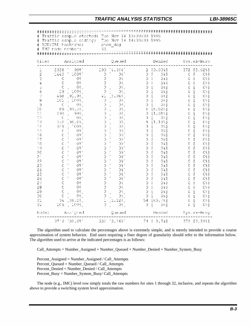
TRAFFIC ANALYSIS STATISTICS LBI-38965C
B-3
######################################################################## Traffic sample started: Tue Nov 14 13:00:00 1995# Traffic sample ending: Tue Nov 14 14:00:00 1995# BCU/CAL hostname: snow_dog# IMC node number: 33#######################################################################
Site: Assigned Queued Denied System-Busy----------------------------------------------------------------------- 1 5958 [ 90%] 290 [4.38%] 2 [0.03%] 372 [5.62%] 2 1443 [ 100%] 0 [ 0%] 0 [ 0%] 0 [ 0%] 3 0 [ 0%] 0 [ 0%] 0 [ 0%] 0 [ 0%] 4 0 [ 0%] 0 [ 0%] 0 [ 0%] 0 [ 0%] 5 0 [ 0%] 0 [ 0%] 0 [ 0%] 0 [ 0%] 6 29 [ 100%] 0 [ 0%] 0 [ 0%] 0 [ 0%] 7 468 [91.9%] 41 [8.06%] 0 [ 0%] 0 [ 0%] 8 101 [ 100%] 0 [ 0%] 0 [ 0%] 0 [ 0%] 9 0 [ 0%] 0 [ 0%] 0 [ 0%] 0 [ 0%]10 86 [93.5%] 0 [ 0%] 6 [6.52%] 0 [ 0%]11 293 [ 99%] 0 [ 0%] 3 [1.01%] 0 [ 0%]12 0 [ 0%] 0 [ 0%] 0 [ 0%] 0 [ 0%]13 752 [98.8%] 0 [ 0%] 9 [1.18%] 0 [ 0%]14 346 [ 100%] 0 [ 0%] 0 [ 0%] 0 [ 0%]15 0 [ 0%] 0 [ 0%] 0 [ 0%] 0 [ 0%]16 0 [ 0%] 0 [ 0%] 0 [ 0%] 0 [ 0%]17 0 [ 0%] 0 [ 0%] 0 [ 0%] 0 [ 0%]18 0 [ 0%] 0 [ 0%] 0 [ 0%] 0 [ 0%]19 0 [ 0%] 0 [ 0%] 0 [ 0%] 0 [ 0%]20 0 [ 0%] 0 [ 0%] 0 [ 0%] 0 [ 0%]21 0 [ 0%] 0 [ 0%] 0 [ 0%] 0 [ 0%]22 0 [ 0%] 0 [ 0%] 0 [ 0%] 0 [ 0%]23 0 [ 0%] 0 [ 0%] 0 [ 0%] 0 [ 0%]24 0 [ 0%] 0 [ 0%] 0 [ 0%] 0 [ 0%]25 0 [ 0%] 0 [ 0%] 0 [ 0%] 0 [ 0%]26 0 [ 0%] 0 [ 0%] 0 [ 0%] 0 [ 0%]27 0 [ 0%] 0 [ 0%] 0 [ 0%] 0 [ 0%]28 0 [ 0%] 0 [ 0%] 0 [ 0%] 0 [ 0%]29 0 [ 0%] 0 [ 0%] 0 [ 0%] 0 [ 0%]30 0 [ 0%] 0 [ 0%] 0 [ 0%] 0 [ 0%]31 34 [38.2%] 1 [1.12%] 54 [60.7%] 0 [ 0%]32 206 [ 100%] 0 [ 0%] 0 [ 0%] 0 [ 0%]
Node: Assigned Queued Denied System-Busy----------------------------------------------------------------------- 9716 [92.6%] 332 [3.16%] 74 [ 0.7%] 372 [3.54%]
The algorithm used to calculate the percentages above is extremely simple, and is merely intended to provide a courseapproximation of system behavior. End users requiring a finer degree of granularity should refer to the information below.The algorithm used to arrive at the indicated percentages is as follows:
Call_Attempts = Number_Assigned + Number_Queued + Number_Denied + Number_System_Busy
Percent_Assigned = Number_Assigned / Call_AttemptsPercent_Queued = Number_Queued / Call_AttemptsPercent_Denied = Number_Denied / Call_AttemptsPercent_Busy = Number_System_Busy/ Call_Attempts
The node (e.g., IMC) level row simply totals the raw numbers for sites 1 through 32, inclusive, and repeats the algorithmabove to provide a switching system level approximation.
LBI-38965C TRAFFIC ANALYSIS STATISTICS
B-4
2. TRAFFIC DISTRIBUTION REPORTThe call traffic distribution file contains information collected on an hourly basis (typically). The file is intended for
import by any popular database package for customer-based calculations of system accessibility and utilization. Typicalapplications of “bouncing busy hour,” loading distribution, average call duration, and daily/weekly activity analysissummaries may be readily derived.
At the top of each hour, 32 records will be written to the file -- one record entry for each possible site. The file(traffic.log) will be opened in “append+” mode, and allowed to grow to a maximum file size of approximately 1.4 Mb (so thatit can be copied to a floppy disk). The file is closed after the records have been written so the customer can delete the file atany time (an error message will be displayed in the unlikely event that the user attempts to delete the file while an update is inprogress).
If the file size exceeds the maximum at the top of an hourly update, it will be renamed to “traffic.old” and the records willbe written to a new “traffic.log” file. Please note that if a current “traffic.old” exists, it will be overwritten.
Each record entry contains 45 comma delimited fields (conceptual columns). The field formats are specified below.
Fields 1 through 8 provide record time stamp information, which delineates when then traffic sampling interval wasconcluded.
Field Description
1 Record type. “1” == the following format. The record type is provided for identificationcompatibility with future releases, which may employ a differing record format.
2 Year (1995 or greater).
3 Month of the year (1 to 12).
4 Day of the month (1 to 31).
5 Hour of the day (0 to 23).
6 Minute of the hour (0 to 59).
7 Second of the minute (0 to 59).
8 Seconds of the sample interval, elapsed prior to time stamp datum specified by Fields 2through 7 (unsigned 32-bit maximum value).
Field 9 identifies the IMC node number associated with this record.
Field Description
9 IMC node number (33 to 64). Zero indicates that the node number is unknown.
Field 10 identifies the site number associated with this record.
Field Description
10 Site number (1 to 32).
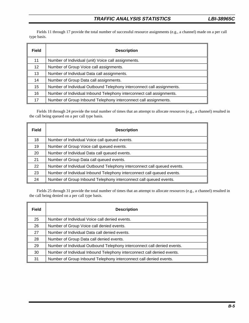
TRAFFIC ANALYSIS STATISTICS LBI-38965C
B-5
Fields 11 through 17 provide the total number of successful resource assignments (e.g., a channel) made on a per calltype basis.
Field Description
11 Number of Individual (unit) Voice call assignments.
12 Number of Group Voice call assignments.
13 Number of Individual Data call assignments.
14 Number of Group Data call assignments.
15 Number of Individual Outbound Telephony interconnect call assignments.
16 Number of Individual Inbound Telephony interconnect call assignments.
17 Number of Group Inbound Telephony interconnect call assignments.
Fields 18 through 24 provide the total number of times that an attempt to allocate resources (e.g., a channel) resulted inthe call being queued on a per call type basis.
Field Description
18 Number of Individual Voice call queued events.
19 Number of Group Voice call queued events.
20 Number of Individual Data call queued events.
21 Number of Group Data call queued events.
22 Number of Individual Outbound Telephony interconnect call queued events.
23 Number of Individual Inbound Telephony interconnect call queued events.
24 Number of Group Inbound Telephony interconnect call queued events.
Fields 25 through 31 provide the total number of times that an attempt to allocate resources (e.g., a channel) resulted inthe call being denied on a per call type basis.
Field Description
25 Number of Individual Voice call denied events.
26 Number of Group Voice call denied events.
27 Number of Individual Data call denied events.
28 Number of Group Data call denied events.
29 Number of Individual Outbound Telephony interconnect call denied events.
30 Number of Individual Inbound Telephony interconnect call denied events.
31 Number of Group Inbound Telephony interconnect call denied events.
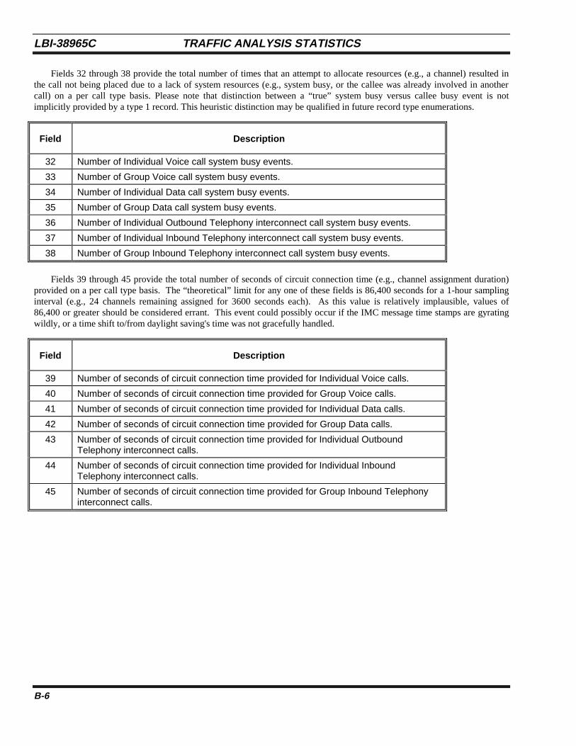
LBI-38965C TRAFFIC ANALYSIS STATISTICS
B-6
Fields 32 through 38 provide the total number of times that an attempt to allocate resources (e.g., a channel) resulted inthe call not being placed due to a lack of system resources (e.g., system busy, or the callee was already involved in anothercall) on a per call type basis. Please note that distinction between a “true” system busy versus callee busy event is notimplicitly provided by a type 1 record. This heuristic distinction may be qualified in future record type enumerations.
Field Description
32 Number of Individual Voice call system busy events.
33 Number of Group Voice call system busy events.
34 Number of Individual Data call system busy events.
35 Number of Group Data call system busy events.
36 Number of Individual Outbound Telephony interconnect call system busy events.
37 Number of Individual Inbound Telephony interconnect call system busy events.
38 Number of Group Inbound Telephony interconnect call system busy events.
Fields 39 through 45 provide the total number of seconds of circuit connection time (e.g., channel assignment duration)provided on a per call type basis. The “theoretical” limit for any one of these fields is 86,400 seconds for a 1-hour samplinginterval (e.g., 24 channels remaining assigned for 3600 seconds each). As this value is relatively implausible, values of86,400 or greater should be considered errant. This event could possibly occur if the IMC message time stamps are gyratingwildly, or a time shift to/from daylight saving's time was not gracefully handled.
Field Description
39 Number of seconds of circuit connection time provided for Individual Voice calls.
40 Number of seconds of circuit connection time provided for Group Voice calls.
41 Number of seconds of circuit connection time provided for Individual Data calls.
42 Number of seconds of circuit connection time provided for Group Data calls.
43 Number of seconds of circuit connection time provided for Individual OutboundTelephony interconnect calls.
44 Number of seconds of circuit connection time provided for Individual InboundTelephony interconnect calls.
45 Number of seconds of circuit connection time provided for Group Inbound Telephonyinterconnect calls.
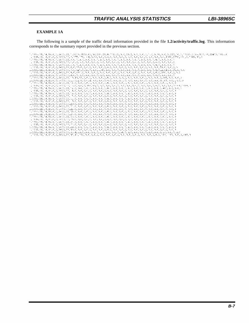
TRAFFIC ANALYSIS STATISTICS LBI-38965C
B-7
EXAMPLE 1A
The following is a sample of the traffic detail information provided in the file 1.2/activity/traffic.log . This informationcorresponds to the summary report provided in the previous section.
1,1995,11,14,14,0,0,3600,33,1,3003,2136,87,96,597,39,0,212,55,0,0,20,3,0,1,0,0,0,1,0,0,26,3,0,0,333,10,0,11867,5045,177,79,29420,1965,0
1,1995,11,14,14,0,0,3600,33,2,375,879,104,0,82,3,0,0,0,0,0,0,0,0,0,0,0,0,0,0,0,0,0,0,0,0,0,0,1368,1770,101,0,2649,63,0
1,1995,11,14,14,0,0,3600,33,3,0,0,0,0,0,0,0,0,0,0,0,0,0,0,0,0,0,0,0,0,0,0,0,0,0,0,0,0,0,0,0,0,0,0,0
1,1995,11,14,14,0,0,3600,33,4,0,0,0,0,0,0,0,0,0,0,0,0,0,0,0,0,0,0,0,0,0,0,0,0,0,0,0,0,0,0,0,0,0,0,0
1,1995,11,14,14,0,0,3600,33,5,0,0,0,0,0,0,0,0,0,0,0,0,0,0,0,0,0,0,0,0,0,0,0,0,0,0,0,0,0,0,0,0,0,0,0
1,1995,11,14,14,0,0,3600,33,6,0,29,0,0,0,0,0,0,0,0,0,0,0,0,0,0,0,0,0,0,0,0,0,0,0,0,0,0,0,73,0,0,0,0,0
1,1995,11,14,14,0,0,3600,33,7,1,427,0,40,0,0,0,1,40,0,0,0,0,0,0,0,0,0,0,0,0,0,0,0,0,0,0,0,2,614,0,34,0,0,0
1,1995,11,14,14,0,0,3600,33,8,0,101,0,0,0,0,0,0,0,0,0,0,0,0,0,0,0,0,0,0,0,0,0,0,0,0,0,0,0,500,0,0,0,0,0
1,1995,11,14,14,0,0,3600,33,9,0,0,0,0,0,0,0,0,0,0,0,0,0,0,0,0,0,0,0,0,0,0,0,0,0,0,0,0,0,0,0,0,0,0,0
1,1995,11,14,14,0,0,3600,33,10,13,73,0,0,0,0,0,0,0,0,0,0,0,0,0,6,0,0,0,0,0,0,0,0,0,0,0,0,0,365,0,0,0,0,0
1,1995,11,14,14,0,0,3600,33,11,3,288,0,0,2,0,0,0,0,0,0,0,0,0,0,3,0,0,0,0,0,0,0,0,0,0,0,0,3,305,0,0,10,0,0
1,1995,11,14,14,0,0,3600,33,12,0,0,0,0,0,0,0,0,0,0,0,0,0,0,0,0,0,0,0,0,0,0,0,0,0,0,0,0,0,0,0,0,0,0,0
1,1995,11,14,14,0,0,3600,33,13,0,0,0,0,696,56,0,0,0,0,0,0,0,0,0,0,0,0,9,0,0,0,0,0,0,0,0,0,0,0,0,0,32401,2488,0
1,1995,11,14,14,0,0,3600,33,14,0,346,0,0,0,0,0,0,0,0,0,0,0,0,0,0,0,0,0,0,0,0,0,0,0,0,0,0,0,400,0,0,0,0,0
1,1995,11,14,14,0,0,3600,33,15,0,0,0,0,0,0,0,0,0,0,0,0,0,0,0,0,0,0,0,0,0,0,0,0,0,0,0,0,0,0,0,0,0,0,0
1,1995,11,14,14,0,0,3600,33,16,0,0,0,0,0,0,0,0,0,0,0,0,0,0,0,0,0,0,0,0,0,0,0,0,0,0,0,0,0,0,0,0,0,0,0
1,1995,11,14,14,0,0,3600,33,17,0,0,0,0,0,0,0,0,0,0,0,0,0,0,0,0,0,0,0,0,0,0,0,0,0,0,0,0,0,0,0,0,0,0,0
1,1995,11,14,14,0,0,3600,33,18,0,0,0,0,0,0,0,0,0,0,0,0,0,0,0,0,0,0,0,0,0,0,0,0,0,0,0,0,0,0,0,0,0,0,0
1,1995,11,14,14,0,0,3600,33,19,0,0,0,0,0,0,0,0,0,0,0,0,0,0,0,0,0,0,0,0,0,0,0,0,0,0,0,0,0,0,0,0,0,0,0
1,1995,11,14,14,0,0,3600,33,20,0,0,0,0,0,0,0,0,0,0,0,0,0,0,0,0,0,0,0,0,0,0,0,0,0,0,0,0,0,0,0,0,0,0,0
1,1995,11,14,14,0,0,3600,33,21,0,0,0,0,0,0,0,0,0,0,0,0,0,0,0,0,0,0,0,0,0,0,0,0,0,0,0,0,0,0,0,0,0,0,0
1,1995,11,14,14,0,0,3600,33,22,0,0,0,0,0,0,0,0,0,0,0,0,0,0,0,0,0,0,0,0,0,0,0,0,0,0,0,0,0,0,0,0,0,0,0
1,1995,11,14,14,0,0,3600,33,23,0,0,0,0,0,0,0,0,0,0,0,0,0,0,0,0,0,0,0,0,0,0,0,0,0,0,0,0,0,0,0,0,0,0,0
1,1995,11,14,14,0,0,3600,33,24,0,0,0,0,0,0,0,0,0,0,0,0,0,0,0,0,0,0,0,0,0,0,0,0,0,0,0,0,0,0,0,0,0,0,0
1,1995,11,14,14,0,0,3600,33,25,0,0,0,0,0,0,0,0,0,0,0,0,0,0,0,0,0,0,0,0,0,0,0,0,0,0,0,0,0,0,0,0,0,0,0
1,1995,11,14,14,0,0,3600,33,26,0,0,0,0,0,0,0,0,0,0,0,0,0,0,0,0,0,0,0,0,0,0,0,0,0,0,0,0,0,0,0,0,0,0,0
1,1995,11,14,14,0,0,3600,33,27,0,0,0,0,0,0,0,0,0,0,0,0,0,0,0,0,0,0,0,0,0,0,0,0,0,0,0,0,0,0,0,0,0,0,0
1,1995,11,14,14,0,0,3600,33,28,0,0,0,0,0,0,0,0,0,0,0,0,0,0,0,0,0,0,0,0,0,0,0,0,0,0,0,0,0,0,0,0,0,0,0
1,1995,11,14,14,0,0,3600,33,29,0,0,0,0,0,0,0,0,0,0,0,0,0,0,0,0,0,0,0,0,0,0,0,0,0,0,0,0,0,0,0,0,0,0,0
1,1995,11,14,14,0,0,3600,33,30,0,0,0,0,0,0,0,0,0,0,0,0,0,0,0,0,0,0,0,0,0,0,0,0,0,0,0,0,0,0,0,0,0,0,0
1,1995,11,14,14,0,0,3600,33,31,4,30,0,0,0,0,0,0,1,0,0,0,0,0,0,54,0,0,0,0,0,0,0,0,0,0,0,0,4,57,0,0,0,0,0
1,1995,11,14,14,0,0,3600,33,32,14,190,0,0,0,2,0,0,0,0,0,0,0,0,0,0,0,0,0,0,0,0,0,0,0,0,0,0,123,1109,0,0,0,447,0
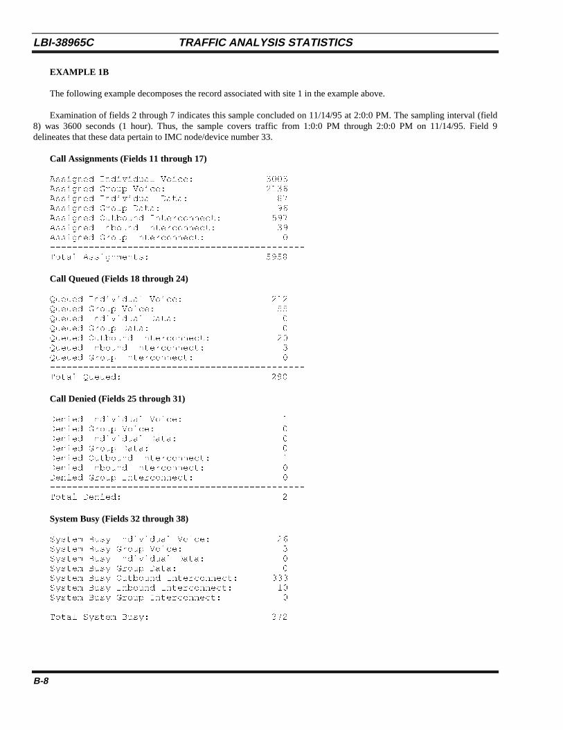
LBI-38965C TRAFFIC ANALYSIS STATISTICS
B-8
EXAMPLE 1B
The following example decomposes the record associated with site 1 in the example above.
Examination of fields 2 through 7 indicates this sample concluded on 11/14/95 at 2:0:0 PM. The sampling interval (field8) was 3600 seconds (1 hour). Thus, the sample covers traffic from 1:0:0 PM through 2:0:0 PM on 11/14/95. Field 9delineates that these data pertain to IMC node/device number 33.
Call Assignments (Fields 11 through 17)
Assigned Individual Voice: 3003Assigned Group Voice: 2136Assigned Individual Data: 87Assigned Group Data: 96Assigned Outbound Interconnect: 597Assigned Inbound Interconnect: 39Assigned Group Interconnect: 0----------------------------------------------Total Assignments: 5958
Call Queued (Fields 18 through 24)
Queued Individual Voice: 212Queued Group Voice: 55Queued Individual Data: 0Queued Group Data: 0Queued Outbound Interconnect: 20Queued Inbound Interconnect: 3Queued Group Interconnect: 0----------------------------------------------Total Queued: 290
Call Denied (Fields 25 through 31)
Denied Individual Voice: 1Denied Group Voice: 0Denied Individual Data: 0Denied Group Data: 0Denied Outbound Interconnect: 1Denied Inbound Interconnect: 0Denied Group Interconnect: 0----------------------------------------------Total Denied: 2
System Busy (Fields 32 through 38)
System Busy Individual Voice: 26System Busy Group Voice: 3System Busy Individual Data: 0System Busy Group Data: 0System Busy Outbound Interconnect: 333System Busy Inbound Interconnect: 10System Busy Group Interconnect: 0----------------------------------------------Total System Busy: 372

TRAFFIC ANALYSIS STATISTICS LBI-38965C
B-9
Airtime (Fields 39 through 45)
Airtime Individual Voice: 11867Airtime Group Voice: 5045Airtime Individual Data: 177Airtime Group Data: 79Airtime Outbound Interconnect: 29420Airtime Inbound Interconnect: 1965Airtime Group Interconnect: 0----------------------------------------------Total Airtime: 48493 (seconds)
EXAMPLE 1C
As a further example, let us examine some behavioral aspects of outbound telephony interconnect calls on site 1.
• Average outbound interconnect call duration: 29420/597 = 49.3 seconds• Percentage outbound interconnect assignments: 597/5958 = 10.0%• Percentage outbound interconnect circuit time: 29420/48493 = 60.7%• Percentage outbound interconnect busy: 333/(597 + 333) = 35.8%
From the above, one first observes that only 10% of resource (e.g., channel) allocations are being performed on behalf ofoutbound telephony interconnect calls. However, 60.7% of the circuit connection time is being dedicated to these calls (hint -call duration can be far more statistically relevant than assignment counts, especially for message trunked calls). From this,one can conclude that the customer profiles subscribed on site 1 are heavy interconnect users. Additionally, note thatapproximately 1 out of 3 users (35.8%) was unable to place said calls due to system busy conditions. In this scenario, thesystem busy events are resulting from the Jessica (PI) having insufficient resources (e.g., IMC 4W audio boards <most likely>or MD110 ISDN T1/E1 DS0 slots <least likely> ) to accommodate the subscriber loading profile. Specifically, in thisexample, the carrier provider should consider increasing the aggregate bandwidth availability of the Jessica PI network entity.

LBI-38965C TRAFFIC ANALYSIS STATISTICS
B-10
This page intentionally left blank
PHYSICAL CONFIGURATION DETAILS LBI-38965C
C-1
APPENDIX CPHYSICAL CONFIGURATION DETAILS
LBI-38965C PHYSICAL CONFIGURATION DETAILS
C-2
This appendix contains information about jumper settings and cable pinouts for the BCU/CAL.
1. JUMPER SETTINGSJumper settings for the BCU/CAL components are shown on the pages listed below.
Figure Page
C.1 TVME 147SA1 Single-Board Computer ..................................................................... C-3C.2 TVME 712/M Transition Module................................................................................ C-4C.3 TVME 147P2 Adapter Board ...................................................................................... C-4C.4 fv5310 Main Board...................................................................................................... C-5C.5 fv5310 Mezzanine Card............................................................................................... C-6C.6 Hard Disk..................................................................................................................... C-7C.7 Teac FD235 Floppy Disk............................................................................................. C-8C.8 Connor CTD4004H-S 114324NP DAT....................................................................... C-9C.9 Archive/Maynard 4324NP DAT.................................................................................. C-9
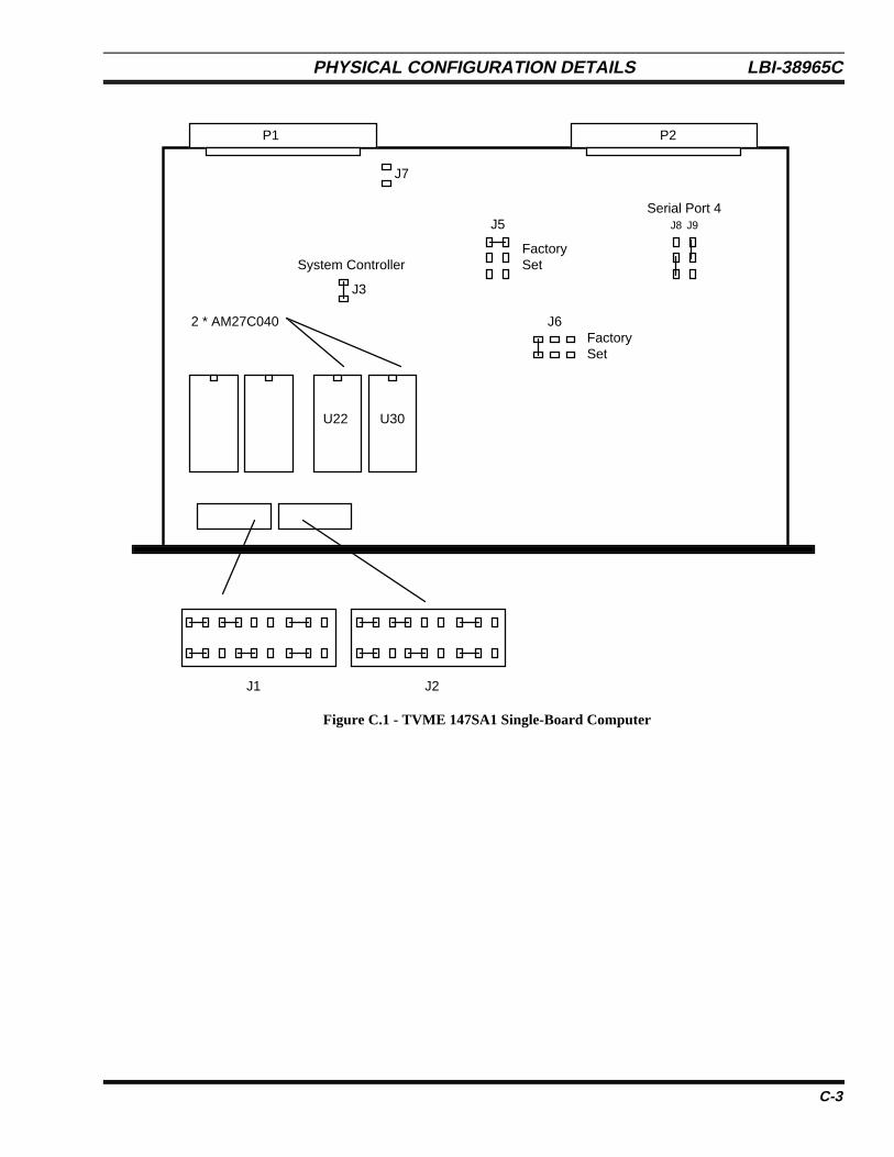
PHYSICAL CONFIGURATION DETAILS LBI-38965C
C-3
J1 J2
2 * AM27C040
U22 U30
FactorySet
P1 P2
J5
J6
J3
System Controller
FactorySet
Serial Port 4J8 J9
J7
Figure C.1 - TVME 147SA1 Single-Board Computer
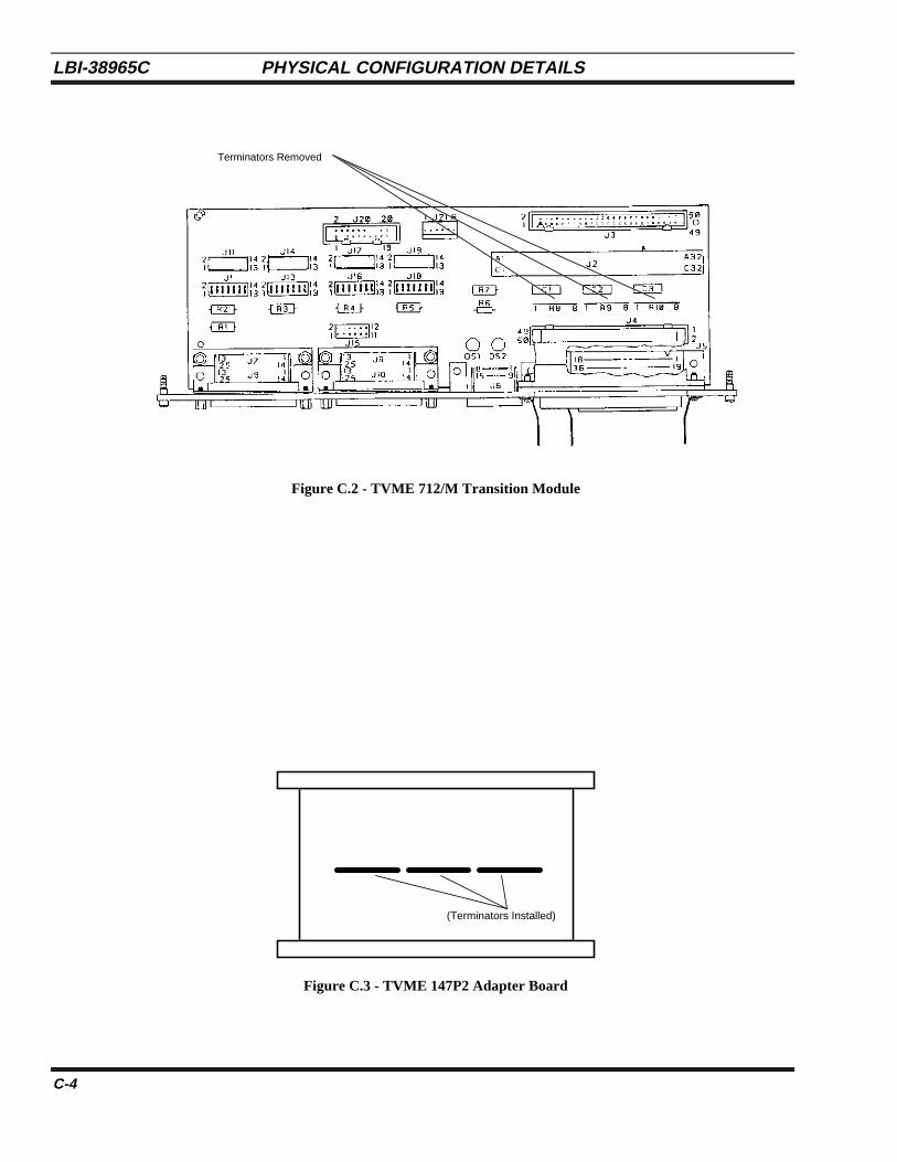
LBI-38965C PHYSICAL CONFIGURATION DETAILS
C-4
Terminators Removed
Figure C.2 - TVME 712/M Transition Module
(Terminators Installed)
Figure C.3 - TVME 147P2 Adapter Board
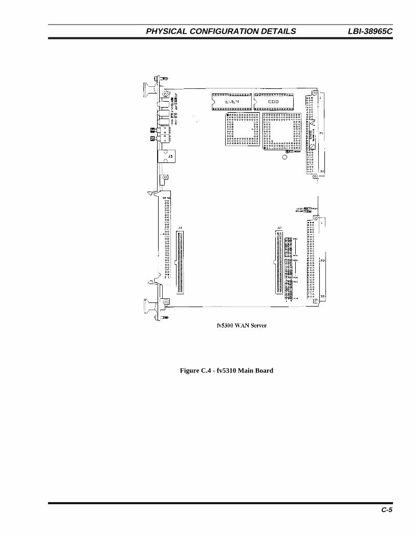
PHYSICAL CONFIGURATION DETAILS LBI-38965C
C-5
Figure C.4 - fv5310 Main Board
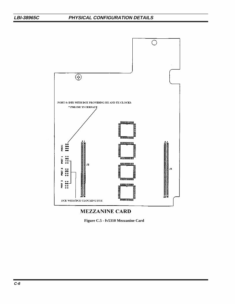
LBI-38965C PHYSICAL CONFIGURATION DETAILS
C-6
Figure C.5 - fv5310 Mezzanine Card
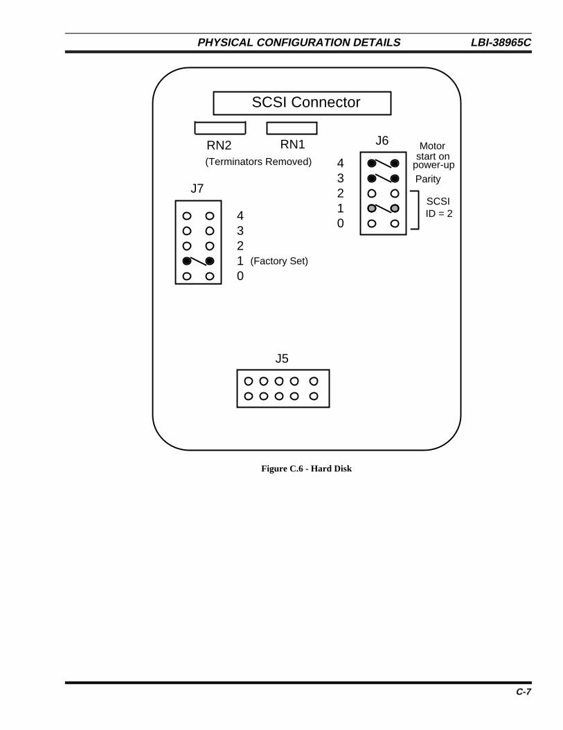
PHYSICAL CONFIGURATION DETAILS LBI-38965C
C-7
J6
J7
J5
01234
01234
SCSI Connector
RN2 RN1(Terminators Removed)
Parity
SCSIID = 2
(Factory Set)
Motorstart on
power-up
Figure C.6 - Hard Disk

LBI-38965C PHYSICAL CONFIGURATION DETAILS
C-8
Pwr
SCSI Conn.
Factory Set Jumpers
R A 2
R A 1
TEAC FD235 (JHF/HF)
ID2
ID1
ID0SCSI ID = 1
(TerminatorsRemoved)
Figure C.7 - Teac FD235 (JHF/HF) Floppy Disk
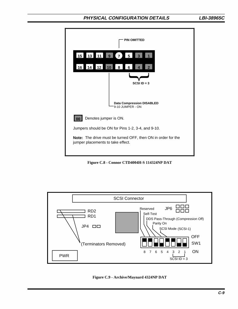
PHYSICAL CONFIGURATION DETAILS LBI-38965C
C-9
9 1
10
7 5 3
16 14 12 8 6 4 2
15 13 11
Data Compression DISABLED9-10 JUMPER - ON
{SCSI ID = 3
PIN OMITTED
Jumpers should be ON for Pins 1-2, 3-4, and 9-10.
Note: The drive must be turned OFF, then ON in order for thejumper placements to take effect.
00 Denotes jumper is ON.
Figure C.8 - Connor CTD4004H-S 114324NP DAT
12345678
SW1
JP6
JP4
RD2RD1
PWR
(Terminators Removed)
SCSI Connector
ON
SCSI ID = 3
Self-Test
Reserved
DDS Pass-Through (Compression Off)Parity On
SCSI Mode (SCSI-1)
OFF
Figure C.9 - Archive/Maynard 4324NP DAT
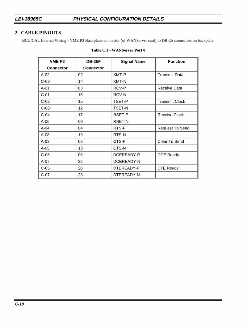
LBI-38965C PHYSICAL CONFIGURATION DETAILS
C-10
2. CABLE PINOUTS
BCU/CAL Internal Wiring - VME P2 Backplane connector (of WANServer card) to DB-25 connectors on backplate
Table C.1 - WANServer Port 0
VME P2
Connector
DB-25F
Connector
Signal Name Function
A-02 02 XMT-P Transmit Data
C-03 14 XMT-N
A-01 03 RCV-P Receive Data
C-01 16 RCV-N
C-02 15 TSET-P Transmit Clock
C-08 12 TSET-N
C-04 17 RSET-P Receive Clock
A-06 09 RSET-N
A-04 04 RTS-P Request To Send
A-08 19 RTS-N
A-03 05 CTS-P Clear To Send
A-05 13 CTS-N
C-06 06 DCEREADY-P DCE Ready
A-07 22 DCEREADY-N
C-05 20 DTEREADY-P DTE Ready
C-07 23 DTEREADY-N
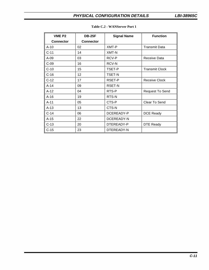
PHYSICAL CONFIGURATION DETAILS LBI-38965C
C-11
Table C.2 - WANServer Port 1
VME P2
Connector
DB-25F
Connector
Signal Name Function
A-10 02 XMT-P Transmit Data
C-11 14 XMT-N
A-09 03 RCV-P Receive Data
C-09 16 RCV-N
C-10 15 TSET-P Transmit Clock
C-16 12 TSET-N
C-12 17 RSET-P Receive Clock
A-14 09 RSET-N
A-12 04 RTS-P Request To Send
A-16 19 RTS-N
A-11 05 CTS-P Clear To Send
A-13 13 CTS-N
C-14 06 DCEREADY-P DCE Ready
A-15 22 DCEREADY-N
C-13 20 DTEREADY-P DTE Ready
C-15 23 DTEREADY-N
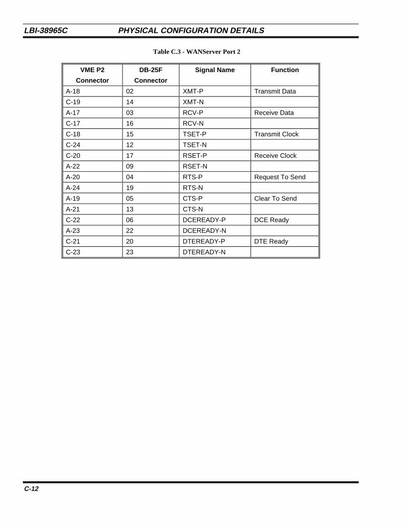
LBI-38965C PHYSICAL CONFIGURATION DETAILS
C-12
Table C.3 - WANServer Port 2
VME P2
Connector
DB-25F
Connector
Signal Name Function
A-18 02 XMT-P Transmit Data
C-19 14 XMT-N
A-17 03 RCV-P Receive Data
C-17 16 RCV-N
C-18 15 TSET-P Transmit Clock
C-24 12 TSET-N
C-20 17 RSET-P Receive Clock
A-22 09 RSET-N
A-20 04 RTS-P Request To Send
A-24 19 RTS-N
A-19 05 CTS-P Clear To Send
A-21 13 CTS-N
C-22 06 DCEREADY-P DCE Ready
A-23 22 DCEREADY-N
C-21 20 DTEREADY-P DTE Ready
C-23 23 DTEREADY-N
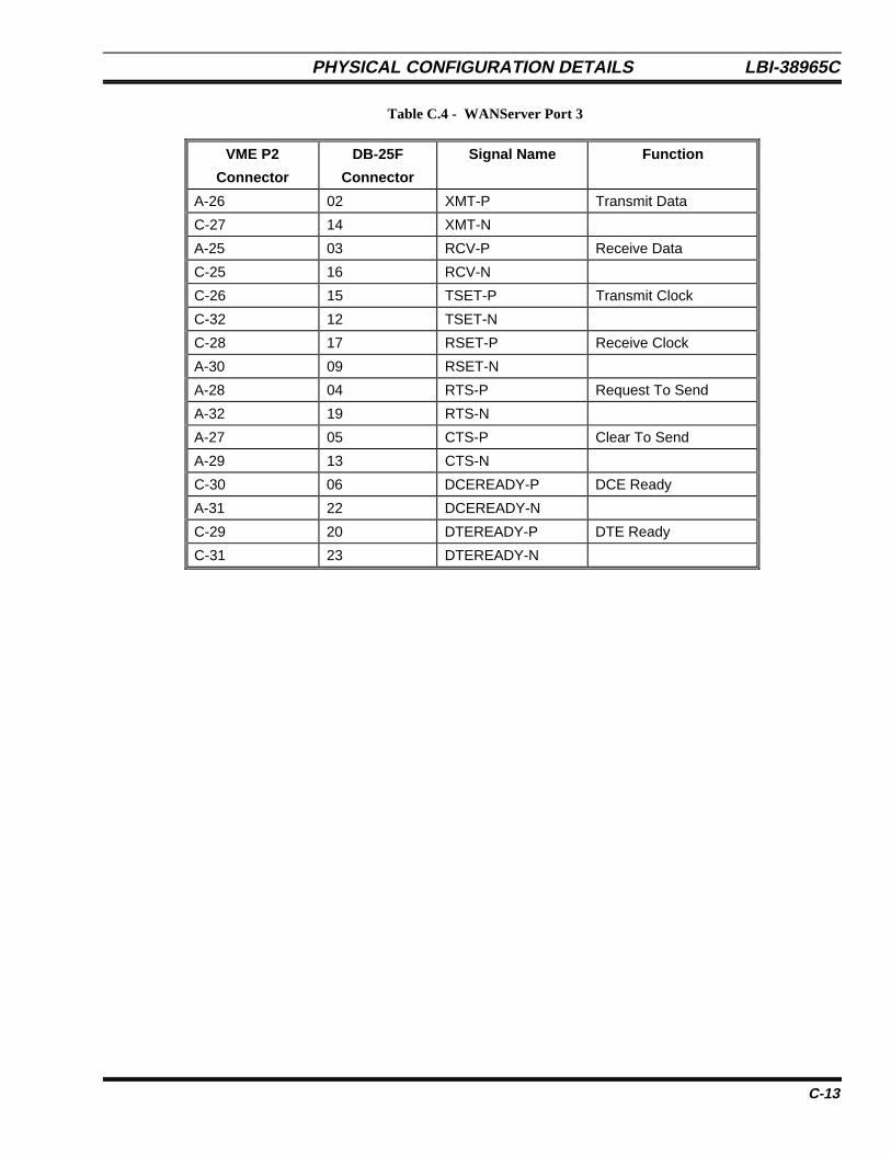
PHYSICAL CONFIGURATION DETAILS LBI-38965C
C-13
Table C.4 - WANServer Port 3
VME P2
Connector
DB-25F
Connector
Signal Name Function
A-26 02 XMT-P Transmit Data
C-27 14 XMT-N
A-25 03 RCV-P Receive Data
C-25 16 RCV-N
C-26 15 TSET-P Transmit Clock
C-32 12 TSET-N
C-28 17 RSET-P Receive Clock
A-30 09 RSET-N
A-28 04 RTS-P Request To Send
A-32 19 RTS-N
A-27 05 CTS-P Clear To Send
A-29 13 CTS-N
C-30 06 DCEREADY-P DCE Ready
A-31 22 DCEREADY-N
C-29 20 DTEREADY-P DTE Ready
C-31 23 DTEREADY-N
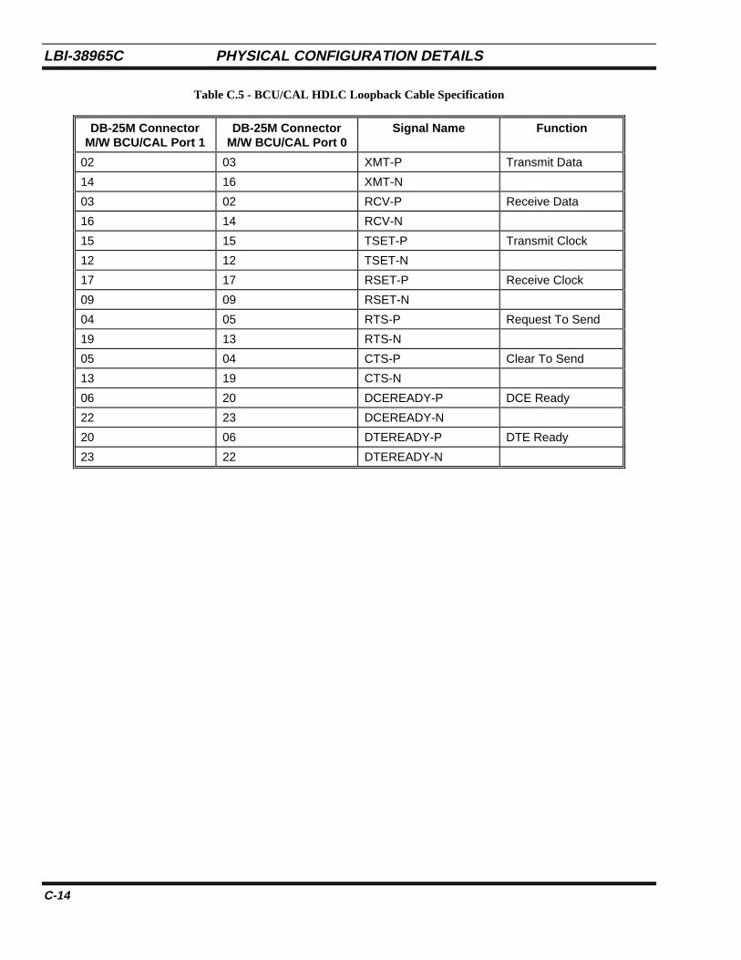
LBI-38965C PHYSICAL CONFIGURATION DETAILS
C-14
Table C.5 - BCU/CAL HDLC Loopback Cable Specification
DB-25M ConnectorM/W BCU/CAL Port 1
DB-25M ConnectorM/W BCU/CAL Port 0
Signal Name Function
02 03 XMT-P Transmit Data
14 16 XMT-N
03 02 RCV-P Receive Data
16 14 RCV-N
15 15 TSET-P Transmit Clock
12 12 TSET-N
17 17 RSET-P Receive Clock
09 09 RSET-N
04 05 RTS-P Request To Send
19 13 RTS-N
05 04 CTS-P Clear To Send
13 19 CTS-N
06 20 DCEREADY-P DCE Ready
22 23 DCEREADY-N
20 06 DTEREADY-P DTE Ready
23 22 DTEREADY-N
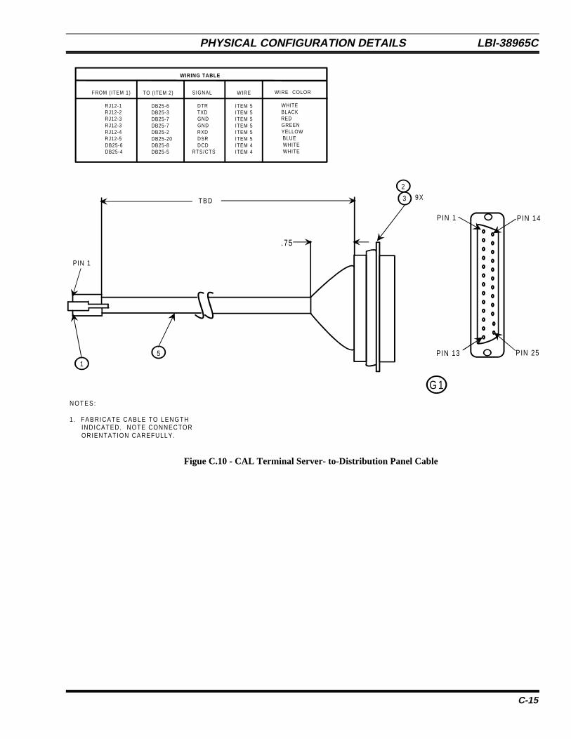
PHYSICAL CONFIGURATION DETAILS LBI-38965C
C-15
2
3 9X
PIN 1
PIN 13
PIN 14
51
PIN 1
TBD
.75
N O T E S :
1 . FABRICATE CABLE TO LENGTH INDICATED. NOTE CONNECTOR ORIENTATION CAREFULLY.
WIRING TABLE
FROM ( ITEM 1)
RJ12-1 RJ12-2 RJ12-3 RJ12-3 RJ12-4 RJ12-5 DB25-6 DB25-4
TO (ITEM 2)
DB25-6 DB25-3 DB25-7 DB25-7 DB25-2 DB25-20 DB25-8 DB25-5
SIGNAL
DTR TXD GND GND RXD DSR DCDRTS/CTS
WIRE
ITEM 5ITEM 5ITEM 5ITEM 5ITEM 5ITEM 5ITEM 4ITEM 4
WIRE COLOR
WHITE BLACK RED GREEN YELLOW BLUE WHITE WHITE
G 1
PIN 25
Figue C.10 - CAL Terminal Server- to-Distribution Panel Cable
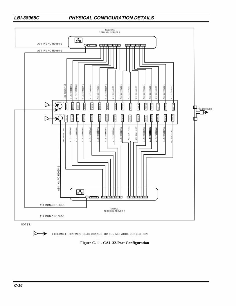
LBI-38965C PHYSICAL CONFIGURATION DETAILS
C-16
J1 J2 J3 J4 J5 J 6 J7 J8 J 9 J 1 0 J 1 1 J12 J13 J14 J15 J 1 6
4203840G1T E R M I N A L S E R V E R 1
4203840G1T E R M I N A L S E R V E R 2
1
J33
PO
RT
2
PO
RT
5
PO
RT
6
J1 J2 J3 J4 J5 J 6 J7 J8 J 9 J10 J 1 1 J12 J13 J14 J15 J 1 6
TO T R A N S C E I V E R
A12
220
3810
G1
A12
220
3810
G1
A12
220
3810
G1
A12
220
3810
G1
A12
220
3810
G1
A12
220
3810
G1
A12
220
3810
G1
A12
220
3810
G1
A12
220
3810
G1
A12
220
3810
G1
A12
220
3810
G1
A12
220
3810
G1
A12
220
3810
G1
A12
220
3810
G1
A12
220
3810
G1
A12
220
3810
G1
A12
220
3810
G1
A12
220
3810
G1
A12
220
3810
G1
A12
220
3810
G1
A12
220
3810
G1
A12
220
3810
G1
A12
220
3810
G1
A12
220
3810
G1
A12
220
3810
G1
A12
220
3810
G1
A12
220
3810
G1
A12
220
3810
G1
A12
220
3810
G1
A12
220
3810
G1
A12
220
3810
G1
A12
220
3810
G1
A12
220
3810
G1
A12
220
3810
G1
A12
220
3810
G1
A12
220
3810
G1
A12
220
3810
G1
A14 INMAC H1060-1
A14 INMAC H1060-1
A14 INMAC H1060-1
A14 INMAC H1060-1
A14
IN
MA
C H
1060
-1
NOTES:
ETHERNET THIN WIRE COAX CONNECTOR FOR NETWORK CONNECTION
J34
E T H E R N E T I N
E T H E R N E T O U T
1
1
PO
RT
1
PO
RT
3
PO
RT
4
PO
RT
7
PO
RT
8
PO
RT
9
PO
RT
10
PO
RT
11
PO
RT
12
PO
RT
13
PO
RT
14
PO
RT
15
PO
RT
16
PO
RT
17
PO
RT
18
PO
RT
19
PO
RT
20
PO
RT
21
PO
RT
22
PO
RT
23
PO
RT
24
PO
RT
25
PO
RT
26
PO
RT
27
PO
RT
28
PO
RT
29
PO
RT
30
PO
RT
31
PO
RT
32
Figure C.11 - CAL 32-Port Configuration
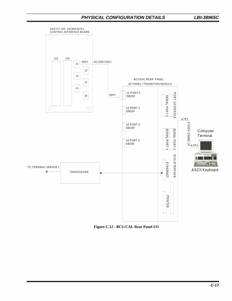
PHYSICAL CONFIGURATION DETAILS LBI-38965C
C-17
Computer Terminal
ASCII Keyboard
A7P 2A7
INM
AC
H35
3-2
A7P 1
PO
RT
1/C
ON
SO
LE
SE
RIA
L PO
RT 3
SE
RIA
L PO
RT 2
SE
RIA
L PO
RT 4
SC
SI IN
TER
FA
CE
ET
HE
RN
ET
PR
INT
ER
J3 PORT 2DB25F
J2 PORT 1DB25F
J4 PORT 3DB25F
J1 PORT 0DB25F
TO T ERM INAL SERVER 1
T RANSCEIVER
A6P1
A6 2203710G 1A6P2J1
J3
J5
J2
J4
J6
J14 J15
EG E PT . NO . 19C852327G 1CO NT RO L INT ERFACE BO ARD
I/O PANEL / TRANSIT IO N MO DULE
BCU/CAL REAR PANEL
Figure C.12 - BCU/CAL Rear Panel I/O

LBI-38965C PHYSICAL CONFIGURATION DETAILS
C-18
This page intentionally left blank

FAULT TOLERANCE LBI-38965C
D-1
APPENDIX DFAULT TOLERANCE
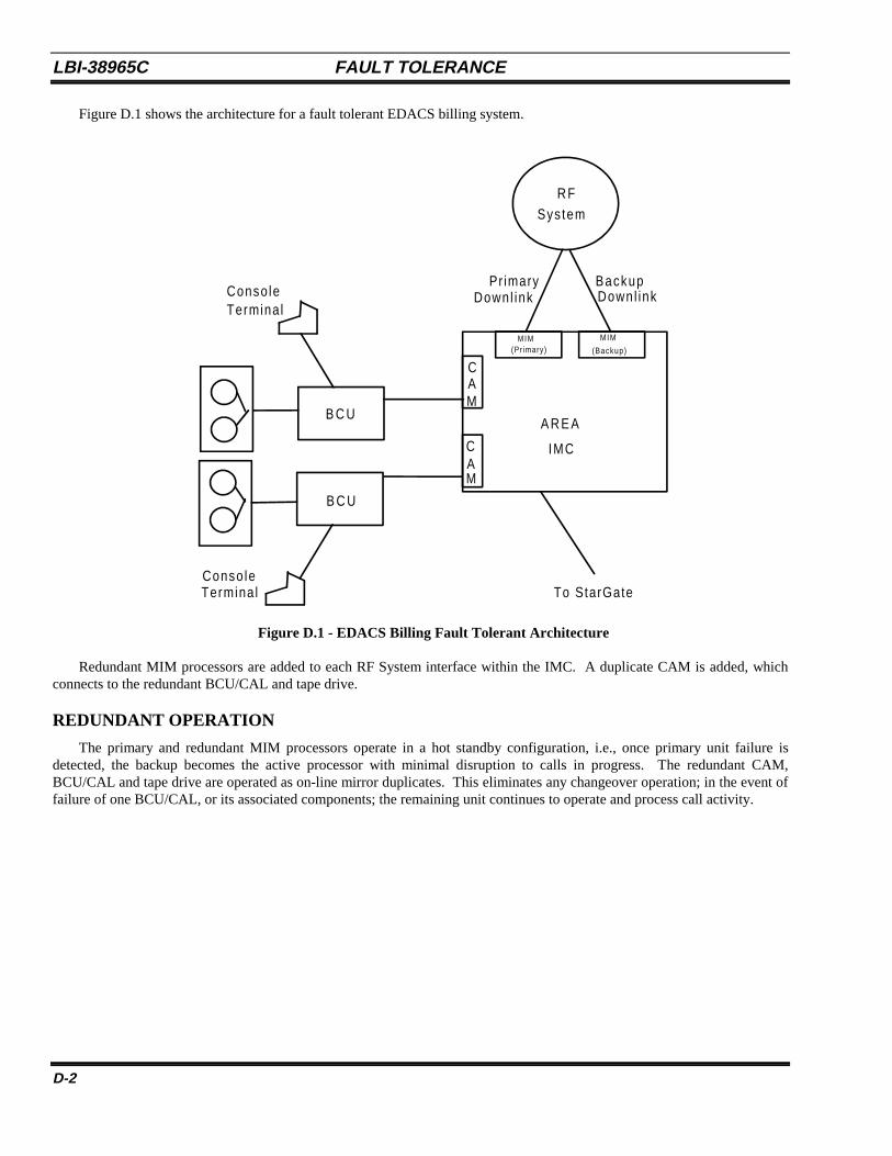
LBI-38965C FAULT TOLERANCE
D-2
Figure D.1 shows the architecture for a fault tolerant EDACS billing system.
R FSystem
Conso leTermina l
MIM(Primary)
MIM
B C U
B C U
CAM
CAM
A R E A
IMC
Conso leTerminal To StarGate
Pr imaryDownl ink
BackupDownl ink
(Backup)
Figure D.1 - EDACS Billing Fault Tolerant Architecture
Redundant MIM processors are added to each RF System interface within the IMC. A duplicate CAM is added, whichconnects to the redundant BCU/CAL and tape drive.
REDUNDANT OPERATION
The primary and redundant MIM processors operate in a hot standby configuration, i.e., once primary unit failure isdetected, the backup becomes the active processor with minimal disruption to calls in progress. The redundant CAM,BCU/CAL and tape drive are operated as on-line mirror duplicates. This eliminates any changeover operation; in the event offailure of one BCU/CAL, or its associated components; the remaining unit continues to operate and process call activity.

LBI-38965C
D-3
This page intentionally left blank

Ericsson Inc.Private Radio SystemsMountain View RoadLynchburg, Virginia 245021-800-528-7711 (Outside USA, 804-528-7711) Printed in U.S.A.