table of contents section page - montana department … of contents section page ... 8.3.4 soil and...
TRANSCRIPT
MDT Geotechnical Manual Subsurface Investigations/Field Tests
July 2008 8-i
Table of Contents
Section Page 8.1 GENERAL ............................................................................................................... 8.1-1
8.1.1 Overview................................................................................................... 8.1-1 8.1.2 Subsurface Exploration Methods.............................................................. 8.1-2 8.1.3 Responsibilities......................................................................................... 8.1-3
8.1.3.1 Geotechnical Section.............................................................. 8.1-3 8.1.3.2 District Role in Exploration Program....................................... 8.1-4 8.1.3.3 Other Units.............................................................................. 8.1-4
8.1.4 References ............................................................................................... 8.1-5
8.2 PRE-FIELD ACTIVITIES......................................................................................... 8.2-1
8.2.1 General..................................................................................................... 8.2-1 8.2.2 Resources ................................................................................................ 8.2-1 8.2.3 Site Visit/Preliminary Field Review ........................................................... 8.2-2 8.2.4 Subsurface Exploration Plan .................................................................... 8.2-3
8.2.4.1 Boring Locations ..................................................................... 8.2-3 8.2.4.2 Content ................................................................................... 8.2-3
8.2.5 Scheduling Drill Crews ............................................................................. 8.2-7 8.2.6 Drill Requests/Permits .............................................................................. 8.2-7 8.2.7 Traffic Control Requirements.................................................................... 8.2-9 8.2.8 Right-of-Entry ........................................................................................... 8.2-9 8.2.9 Utility Locations ........................................................................................ 8.2-9 8.2.10 Railroads .................................................................................................. 8.2-10
8.3 FIELD WORK.......................................................................................................... 8.3-1
8.3.1 Location and Depth of Explorations.......................................................... 8.3-1 8.3.2 Surveying and Location Tolerance ........................................................... 8.3-1 8.3.3 Exploration Numbering System................................................................ 8.3-2 8.3.4 Soil and Rock Drilling ............................................................................... 8.3-2
8.3.4.1 Drilling Equipment................................................................... 8.3-2 8.3.4.2 Drilling Equipment Selection................................................... 8.3-2 8.3.4.3 Drilling Considerations............................................................ 8.3-3 8.3.4.4 Special Concerns.................................................................... 8.3-4
8.3.5 Sampling Methods (Soils)......................................................................... 8.3-5
MDT Geotechnical Manual Subsurface Investigations/Field Tests
8-ii July 2008
Table of Contents (Continued)
Section Page
8.3.5.1 General ................................................................................... 8.3-5 8.3.5.2 Sampling Interval .................................................................... 8.3-6 8.3.5.3 Sample Numbering ................................................................. 8.3-8 8.3.5.4 Transportation of Soil Samples............................................... 8.3-8
8.3.6 Sampling Methods (Rock) ........................................................................ 8.3-9
8.3.6.1 Exploration and Investigation Methods................................... 8.3-9 8.3.6.2 Transportation and Storage of Samples ................................. 8.3-9
8.3.7 Field Soil and Rock Classification ............................................................ 8.3-10 8.3.8 Piezometers and Monitoring Well Installation........................................... 8.3-12
8.3.8.1 General ................................................................................... 8.3-12 8.3.8.2 Information from Existing Wells .............................................. 8.3-12 8.3.8.3 Open Borings.......................................................................... 8.3-13 8.3.8.4 Observation Wells and Piezometers....................................... 8.3-13 8.3.8.5 Water Level Measurements .................................................... 8.3-14 8.3.8.6 Well Closure ........................................................................... 8.3-14 8.3.8.7 Regulations............................................................................. 8.3-14
8.3.9 Field/In-Situ Tests..................................................................................... 8.3-15
8.3.9.1 General ................................................................................... 8.3-15 8.3.9.2 MDT Equipment ...................................................................... 8.3-16 8.3.9.3 Standard Penetration Test ...................................................... 8.3-16 8.3.9.4 Vane Shear Test ..................................................................... 8.3-17 8.3.9.5 Cone Penetration Test (CPT) ................................................. 8.3-18 8.3.9.6 Geophysical Surveys .............................................................. 8.3-19 8.3.9.7 Other Testing Methods ........................................................... 8.3-20
8.3.10 Borehole Completion and Site Restoration .............................................. 8.3-20
8.4 POST FIELD WORK ............................................................................................... 8.4-1
8.4.1 Boring Log Preparation............................................................................. 8.4-1 8.4.2 Lab Tests.................................................................................................. 8.4-1 8.4.3 Reports ..................................................................................................... 8.4-1
MDT Geotechnical Manual Subsurface Investigations/Field Tests
July 2008 8.1-1
Chapter 8 SUBSURFACE INVESTIGATIONS/FIELD TESTS
8.1 GENERAL
8.1.1 Overview
Subsurface investigations and field tests are conducted by the MDT's Geotechnical Section Field Investigation Unit. Direction and oversight are provided by the Geotechnical Engineer and/or Geotechnical Operations Manager with day-to-day coordination through the project geotechnical specialist. Subsurface investigations and field testing are performed for MDT projects that require geotechnical involvement and, therefore, the demands on the Field Investigation Unit are usually very high. Careful planning and coordination are required by the project geotechnical specialist to ensure that the field work is carried out within the project schedule and budget, and without negatively affecting other ongoing projects.
The following identifies subsurface investigations and field test activities, including the tasks associated with each. The Geotechnical Section is either responsible for these activities or coordinates with the Districts or other MDT Units to have these activities performed:
1. Pre-Field Activities. Pre-field investigation activities related to subsurface investigations include:
• processing right-of-entry forms, • contacting affected landowners before entering property, • arranging for control of traffic, • acquiring necessary permits, • ensuring that the utilities location checks have been performed, • coordinating with affected railroad companies, and • arranging for field surveying.
2. Field Activities. Subsurface investigation field activities include:
• identifying the location of all borings based on directions from the project geotechnical specialist;
• selecting and transporting the appropriate drill rig equipment to the site;
• preparing the site for drilling;
• logging drilling activities;
• recovering soil and rock samples;
• performing the necessary field in-situ tests;

MDT Geotechnical Manual Subsurface Investigations/Field Tests
8.1-2 July 2008
• preparing and transporting the soil or rock samples back to the Geotechnical Section office in Helena;
• performing, where applicable, the necessary field work for installations of piezometers, monitoring/observation well installations, inclinometers and other instrumentation; and
• restoring the borehole site to its original condition to the extent practical.
3. Post Field Activities. Post-field activities include:
• organizing the field data,
• presenting the field data on the Log of Boring Form,
• submitting test requests to the Geotechnical Laboratory and working with the Geotechnical Laboratory staff in the interpretation of laboratory results,
• interpreting conditions at the project site based on the results of the field work and laboratory testing, and
• completing documentation required for project files.
8.1.2 Subsurface Exploration Methods
The MDT Geotechnical Section typically uses the following subsurface exploration methods:
1. Drilling and Sampling Soil and Rock. Drilling and sampling is performed to evaluate soil or rock conditions at the site and to obtain disturbed and undisturbed soil or rock samples for laboratory classification and testing:
a. Disturbed Samples. Disturbed samples are obtained to determine the soil type, gradation, Atterberg limits, consistency, moisture content and density, presence of contaminants, stratification, etc. Disturbed samples may be obtained by hand excavating methods or by mechanical digging or drilling techniques. These samples are considered “disturbed” because the sampling process modifies their natural structure.
b. Undisturbed Samples. Undisturbed samples are used to determine the in-situ density, strength, compressibility or swell potential, permeability, discontinuities, fractures and fissures of subsurface formations. Even though these samples are designated as “undisturbed,” in reality they are disturbed to varying degrees. The degree of disturbance depends on the type of subsurface materials, type and condition of sampling equipment used, skill of the drillers, and storage and transportation methods used. Serious and costly inaccuracies may be introduced into the design if proper protocol and care is not exercised during recovery, transporting or storing of the samples.
MDT Geotechnical Manual Subsurface Investigations/Field Tests
July 2008 8.1-3
The drilling and sampling program is also conducted as part of in-situ testing to establish groundwater conditions and sometimes to support the installation of geotechnical instrumentation.
2. In-Situ Testing. In-situ testing methods can be used as part of or to supplement drilling and sampling methods. These tests include the standard penetration test (SPT), electric cone penetrometer test (CPT), vane shear test (VST) and pressuremeter test (PMT). Some of these tests provide information on subsurface soil characteristics without obtaining a sample of the soil. Stratigraphy and engineering characteristics of the soil are interpreted based on the types of information recorded and by using empirical correlations between the test measurement and soil properties. Considerable time and cost savings can often be obtained by supplementing conventional drilling and sampling with some of these in-situ testing methods.
3. Geophysical Testing. Geophysical testing is used to obtain information about the stratigraphy and, in some cases, engineering characteristics of the geologic unit. The seismic refraction method is the most common geophysical method used by the Geotechnical Section; however, other non-seismic geophysical tests (e.g., surface resistivity (SR), ground penetrating radar (GPR), electromagnetic conductivity (EM) can also be considered. The non-seismic geophysical methods can be useful in establishing ground stratigraphy, detecting sudden changes in subsurface formations, locating underground cavities in karst formations or identifying underground utilities and/or obstructions. Compression (P-wave) and shear (S-wave) wave velocities obtained from seismic geophysical tests (e.g., downhole, crosshole) can provide information on the dynamic elastic properties of the soil and rock. The profile of shear wave velocity can be used for seismic site amplification studies of ground shaking and can be used for soil liquefaction evaluations. The P-wave velocity can be used to estimate if the rock can be excavated by various sizes of equipment.
8.1.3 Responsibilities
The primary responsibility of the subsurface investigations and field test work resides with the Geotechnical Section. However, as discussed below, the Districts and the other MDT Units often have a critical role in the subsurface investigations and field programs.
8.1.3.1 Geotechnical Section
The project geotechnical specialist should determine the scope of the exploration program after reviewing the project requirements. The project geotechnical specialist also coordinates the exploration work with the Field Investigation Unit supervisor and, if required, the Geotechnical Operations Manager. During the investigation, the project geotechnical specialist logs explorations, coordinates and records results of field testing, and transports samples back to the Geotechnical Section for laboratory testing.
Many of the Pre-Field Activities listed in Section 8.1.1 are handled by the District staff. The project geotechnical specialist and Field Investigations Unit supervisor should coordinate with the District to:

MDT Geotechnical Manual Subsurface Investigations/Field Tests
8.1-4 July 2008
• discuss the planned location, scope and schedule for the exploration work;
• identify nearby features that could change the subsurface exploration plans (e.g., near by sinkholes, landfills, unstable slopes);
• determine and set up the traffic control plan;
• arrange for other logistical support (e.g., access to site, survey); and/or
• review previous construction and operational performance in the area, if available.
The project geotechnical specialist coordinates with the Hydraulic Section for projects near streams and rivers and with the Environmental Services Bureau if contaminated soils are anticipated. These contacts are made to establish if special exploration requirements or restrictions need to be considered. Chapter 2 provides a more detailed discussion of overall coordination requirements.
8.1.3.2 District Role in Exploration Program
The District’s role in the exploration program consists of the following:
• preparing access to the site (when required), • assisting in the traffic control during the investigations (when required), • surveying the site, • contacting the landowner to obtain the right-of-entry form, • helping with the closure of the borehole (when required), and • cleaning up the site after drilling is complete (when required). The District may also provide information about geotechnical conditions within the upper 10 ft (3 m) of soil profile based on shallow explorations conducted for pavement design. The District can also provide useful information regarding groundwater conditions, unusual soil or rock conditions to anticipate and special equipment required to support the field exploration program. Chapter 1 summarizes the role of the District within the MDT organization.
8.1.3.3 Other Units
Depending on the scope of the particular project, the Geotechnical Section may coordinate with the following Units:
1. Hydraulics Section. These contacts are made if the exploration will be located close to a lake, stream or river to establish any special restrictions during the exploration or information that may be required to support the hydraulics assessment at the site.
2. Environmental Services Bureau. These contacts are made if contaminated soil or groundwater occur; if work must be conducted in or near wetlands, rivers, lakes or other bodies of water; or if other environmental factors were identified during the site reconnaissance. The objective of the contact can range from requesting permits (e.g., Section 404, SPA 124) to conducting environmental studies for the drilling site.

MDT Geotechnical Manual Subsurface Investigations/Field Tests
July 2008 8.1-5
Chapter 2 provides additional information on coordination with other Units within MDT.
8.1.4 References
For further guidance on subsurface investigations and field tests, the project geotechnical specialist should review the following documents:
• Subsurface Investigations – Geotechnical Site Characterization, NHI-01-031, FHWA;
• Checklist and Guidelines for Review of Geotechnical Reports and Preliminary Plans and Specifications, ED-88-053, FHWA; and
• ASTM Specifications for various field exploration and testing methods.

MDT Geotechnical Manual Subsurface Investigations/Field Tests
8.1-6 July 2008

MDT Geotechnical Manual Subsurface Investigations/Field Tests
July 2008 8.2-1
8.2 PRE-FIELD ACTIVITIES
8.2.1 General
This Section discusses the tasks that the project geotechnical specialist needs to complete in support of the pre-field activities. These tasks include review of existing information and site reconnaissance. Information from this preliminary work is used to develop a subsurface exploration plan that will be used by the Field Investigations Unit to schedule and conduct the field work.
8.2.2 Resources
The first step in the investigation process is to review existing data. There are a number of helpful sources that should be used in planning subsurface investigations. Review of this information can minimize surprises in the field, assist in determining boring locations and depths and provide valuable geologic and historical information for inclusion in the Geotechnical Report.
The following is a partial list of useful sources of important site, geologic and historic information that should be considered:
• prior subsurface investigation (historic data) at or near the project site;
• prior construction and structural performance records at the site (e.g., pile length, drivability problems, rock slides, excessive seepage, unpredicted settlement, poor pavement performance). Some of this information may be obtained from the District;
• prior environmental studies;
• site plans showing locations of ditches, driveways, culverts, utilities and pipelines;
• maps of streams, rivers and other water bodies crossed by bridges, culverts, etc., including bathometric data;
• aerial photographs (e.g., MDT Photogrammetry and Survey Section, USGS, Google Earth);
• US Geological Survey (maps, reports, publications and websites);
• Montana Geological Survey (maps, reports and publications);
• US Department of Agriculture Natural Resources Conservation Service (NCRS) soil maps. These are the same as the former Soil Conservation Service soils maps. These maps only show shallow surficial deposits (i.e., usually limited to 60 in (1.5 m) in depth), but may assist in establishing frost penetration depths, drainage characteristics, erosion susceptibility and agrarian data;
• local university libraries and geology departments;
MDT Geotechnical Manual Subsurface Investigations/Field Tests
8.2-2 July 2008
• water well locations from the Montana Department of Natural Resources and Conservation (DNRC) Natural Resources Information System (NRIS);
• earthquake data, seismic hazard maps, fault maps and related information provided by:
+ US Geological Survey (USGS); + Montana Bureau of Mines and Geology (MBMG) website; and + other special publications (e.g., DNRC maps, seismic hazard maps); and
• US Bureau of Mines.
8.2.3 Site Visit/Preliminary Field Review
It is imperative that the project geotechnical specialist and, if possible, the District Geotechnical Manager, conduct a reconnaissance visit to the project site to identify topographic and geologic features of the site and become knowledgeable of access and working conditions. The site visit is most effective when conducted after the available information for the project site has been collected and reviewed.
The preliminary field review and/or site visit is a good opportunity to discuss or review:
• design and construction plans;
• general site conditions;
• geologic issues;
• geomorphology;
• drilling equipment access restrictions;
• traffic control requirements during field investigations;
• location of underground and overhead utilities;
• type and condition of existing facilities (e.g., pavements, bridges);
• adjacent land use (e.g., buildings, waterways, irrigation practices, public/private, urban/rural, developed/undeveloped);
• potential for working hour restrictions;
• right-of-way constraints;
• environmental issues;
• escarpments, outcrops, erosion features and surface settlement;
• flood levels;

MDT Geotechnical Manual Subsurface Investigations/Field Tests
July 2008 8.2-3
• water traffic and access to water boring sites;
• benchmarks and other reference points to aid in the location of boreholes; and
• equipment storage areas and security.
8.2.4 Subsurface Exploration Plan
The project geotechnical specialist, in coordination with the District Geotechnical Manager, is responsible for determining the number and locations of boreholes, required sampling, required equipment to collect and test the samples, and field instrumentation requirements. These determinations are based on the type, size and complexity of the project and the geological conditions that are anticipated. The project geotechnical specialist should document the plans for field work and testing in the Subsurface Exploration Plan. The following Sections describe issues to consider when developing the Subsurface Exploration Plan. When completed, this information is reviewed by the District Geotechnical Manager and then forwarded to the Field Investigation Unit via a Drill Request Memorandum to conduct the field work. The Drill Request Memorandum is also sent to the District Biologist to initiate the required permitting for drilling in the vicinity of streams, wetlands or other sensitive areas.
8.2.4.1 Boring Locations
The number, depth, spacing and type of borings are greatly dependent on site conditions, the type of project and its requirements. Consequently, no “rigid” rules can be established. Usually the extent of the work is established as the site investigation progresses in the field. Figure 8.2-A provides MDT guidelines to determine the number, depth and spacing of boreholes. Also, see the FHWA Subsurface Investigations Manual for additional guidelines on determining the number, depth and spacing of borings.
After the borehole locations are selected, the project geotechnical specialist coordinates the marking of these locations in the field. Typically, the locations can be marked using GPS or cloth tapes and a hand level. Where the borehole location accuracy is critical, the project geotechnical specialist should request the Survey Section to mark the locations in the field. Section 8.3.2 provides accuracy guidelines for surveying borehole locations.
8.2.4.2 Content
The content of the Subsurface Exploration Plan should include the following information:
• contacts and phone numbers for the landowner, utility companies, railroads, etc.; • number and location for the boreholes; • type of equipment expected to accomplish the drilling; • expected minimum depth of each borehole; • type of exploration required; • sampling type and interval; • in-situ testing procedures required;

MDT Geotechnical Manual Subsurface Investigations/Field Tests
8.2-4 July 2008
Geotechnical Feature Minimum Number of Borings Minimum Depth of Borings
Shallow Foundations
Provide at least 1 boring per substructure unit ≤ 100 ft (30 m) in width. Provide at least 2 borings per substructure unit > 100 ft (30 m) in width. Provide additional borings in areas where erratic subsurface conditions are encountered.
Depth of exploration should be:
• great enough to fully penetrate unsuitable foundation soils (e.g., peat, organic silt, soft fine grained soils) into competent material of suitable resistance (e.g., stiff to hard cohesive soil) or compact to dense cohesionless soil or bedrock;
• at least to a depth where stress increase due to estimated foundation load is less than 10% of the existing effective overburden stress at that depth; and
• if bedrock is encountered, before the depth required by the second criterion above is achieved, exploration depth should be great enough to penetrate a minimum of 10 ft (3.0 m) into the bedrock, but rock exploration should be sufficient to characterize compressibility of infill material of near-horizontal to horizontal discontinuities.
Note that for highly variable bedrock conditions, or in areas where very large boulders are likely, more than 10 ft (3.0 m), of rock core may be required to verify that adequate quality bedrock is present.
Deep Foundations
Provide at least 1 boring per bridge pier location for driven piles Provide at least 1 boring per drilled shaft location, unless the shaft is part of a group, in which case a single boring per group is sufficient Provide additional borings in areas where erratic subsurface conditions are encountered, especially for shafts socketed into bedrock.
In soil, depth of exploration should extend below the anticipated pile or shaft tip elevation a minimum of 20 ft (6.0 m), or a minimum of 2 times the maximum pile group dimension, whichever is deeper. All borings should extend through unsuitable strata (e.g., unconsolidated fill, peat, highly organic materials, soft fine-grained soils, loose coarse-grained soils) to reach hard or dense material. For piles bearing on rock, obtain a minimum of 10 ft (3.0 m) of rock core at each exploration point location to verify that the boring has not terminated on a boulder.
Figure 8.2-A ⎯ MINIMUM BORING GUIDELINES
MDT Geotechnical Manual Subsurface Investigations/Field Tests
July 2008 8.2-5
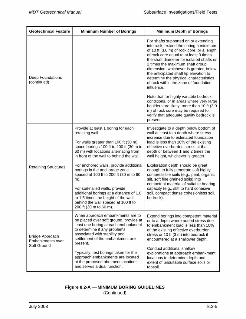
Geotechnical Feature Minimum Number of Borings Minimum Depth of Borings
Deep Foundations (continued)
For shafts supported on or extending into rock, extend the coring a minimum of 10 ft (3.0 m) of rock core, or a length of rock core equal to at least 3 times the shaft diameter for isolated shafts or 2 times the maximum shaft group dimension, whichever is greater, below the anticipated shaft tip elevation to determine the physical characteristics of rock within the zone of foundation influence. Note that for highly variable bedrock conditions, or in areas where very large boulders are likely, more than 10 ft (3.0 m) of rock core may be required to verify that adequate quality bedrock is present.
Retaining Structures
Provide at least 1 boring for each retaining wall. For walls greater than 100 ft (30 m), space borings 100 ft to 200 ft (30 m to 60 m) with locations alternating from in front of the wall to behind the wall. For anchored walls, provide additional borings in the anchorage zone spaced at 100 ft to 200 ft (30 m to 60 m). For soil-nailed walls, provide additional borings at a distance of 1.0 to 1.5 times the height of the wall behind the wall spaced at 100 ft to 200 ft (30 m to 60 m).
Investigate to a depth below bottom of wall at least to a depth where stress increase due to estimated foundation load is less than 10% of the existing effective overburden stress at that depth or between 1 and 2 times the wall height, whichever is greater. Exploration depth should be great enough to fully penetrate soft highly compressible soils (e.g., peat, organic silt, soft fine grained soils) into competent material of suitable bearing capacity (e.g., stiff to hard cohesive soil, compact dense cohesionless soil, bedrock).
Bridge Approach Embankments over Soft Ground
When approach embankments are to be placed over soft ground, provide at least one boring at each embankment to determine if any problems associated with stability and settlement of the embankment are present. Typically, test borings taken for the approach embankments are located at the proposed abutment locations and serves a dual function.
Extend borings into competent material or to a depth where added stress due to embankment load is less than 10% of the existing effective overburden stress or 10 ft (3 m) into bedrock if encountered at a shallower depth. Conduct additional shallow explorations at approach embankment locations to determine depth and extent of unsuitable surface soils or topsoil.
Figure 8.2-A ⎯ MINIMUM BORING GUIDELINES (Continued)

MDT Geotechnical Manual Subsurface Investigations/Field Tests
8.2-6 July 2008
Geotechnical Feature Minimum Number of Borings Minimum Depth of Borings
Roadways
Provide borings at a minimum spacing of approximately 1000 ft (300 m). Consider providing additional borings in areas of erratic subsurface conditions.
Extend the boring 6 ft (2 m) below the proposed subgrade level.
Roadway Cuts and Embankments
Typically, space borings every 200 ft (60 m) (erratic conditions) to 400 ft (120 m) (uniform conditions) with at least one boring taken in each separate landform. For high cuts and fills and other critical locations, provide a minimum of 3 borings along a line perpendicular to centerline or planned slope face to establish geologic cross-section for analysis.
Cuts: In stable materials extend the borings a minimum 15 ft (5 m) below the depth of cut at the ditch line and, in weak soils, extend the borings below the grade to firm materials or to twice the depth of cut, whichever occurs first. Embankments: Extend borings to a hard stratum or to a depth of twice the embankment height.
Landslides
Provide a minimum of 3 borings along a line perpendicular to the centerline or planned slope face to establish geologic cross-section for analysis. The actual number of borings depends on the extent of stability problem. For active slides, place at least one boring above and below the slide area.
Extend borings to an elevation below active or potential failure surface and into hard stratum, or to a depth for which failure is unlikely because of geometry of cross-section. Slope inclinometers used to locate the depth of an active slide must be extended below the base of slide.
Ground Improvement Techniques
Varies widely depending in the ground improvement technique(s) being employed. For more information, see FHWA Ground Improvement Technical Summaries, FHWA SA-98-086R.
Material Sites (Borrow sources, Quarries)
Space borings every 100 ft to 200 ft (30 m to 60 m).
Extend exploration to the base of deposit or to a depth required to provide needed quantity.
Note: Modifications may be made to the above criteria for large projects, low-traffic volumes, rural locations, soil conditions and geologic complexity. The project geotechnical specialist should discuss proposed modifications with the Geotechnical Operations Manager or Geotechnical Engineer to confirm the reasonableness of the modification.
Figure 8.2-A ⎯ MINIMUM BORING GUIDELINES (Continued)
MDT Geotechnical Manual Subsurface Investigations/Field Tests
July 2008 8.2-7
• instrumentation plans; • borehole closure requirements; • site restoration requirements; and • discussions of unusual conditions expected (e.g., hazardous materials, artesian wells). Also, a site plan should normally be developed showing key information identified above. The plan should be developed by the project geotechnical specialist and sent to the Field Investigation Unit with the Subsurface Exploration Plan.
8.2.5 Scheduling Drill Crews
The project geotechnical specialist coordinates with the Geotechnical Engineer, Geotechnical Operations Manager and the Field Investigation Unit Supervisor to schedule the drilling and field investigations. Scheduling should take into account the time required to coordinate with the utility companies, railroad companies and landowners, and the time it takes to receive the necessary permits. The Geotechnical Engineer, Geotechnical Operations Manager, project geotechnical specialist and Field Investigation Unit Supervisor will review the existing workload, priorities and capabilities of the MDT drilling crews, determine an anticipated starting date and, when required, the need to retain the services of an outside contractor to conduct the field investigation.
Consultants/contractors are often used for the following types of field services:
• additional drilling capacity for the Geotechnical Section; • specialized in-situ testing (e.g., ATV-mounted CPT, PMT); • steep slope or horizontal drilling; • over-water drilling; • special geophysical testing (e.g., crosshole, downhole, resistivity); and • other field services not handled by MDT. If an outside consultant/contractor is used to provide the field services, allow sufficient time for a contract to be developed and negotiated with the outside consultant/contractor. The length of time to have the consultant/contractor on site and performing field work will usually be 4 to 6 weeks and may be longer in the busy summer months.
8.2.6 Drill Requests/Permits
Where it is known or expected that a permit is required, the project geotechnical specialist requests, with the Drill Request Memorandum, the District Biologist within the Environmental Services Bureau to obtain the necessary permits. Figure 8.2-B provides guidelines on what permits may be required when drilling will occur near streams, wetlands and floodplains; however, Environmental Services Bureau personnel should determine the necessary permits. It typically requires a maximum of 60 days to obtain the necessary permits.

MDT Geotechnical Manual Subsurface Investigations/Field Tests
8.2-8 July 2008
Using the diagram above, determine where borings will be located – streambed, streambanks, wetlands or floodplain. The letters in the diagram refer to the required permits listed below (A through L):
A. Montana Natural Streambed and Land Preservation Act (310 Permit)
B. Montana Stream Protection Act (SPA 124 Permit)
C. Montana Floodplain and Floodway Management Act (Floodplain Development Permit)
D. Federal Clean Water Act (404 Permit)
E. Federal Rivers and Harbors Act (Section 10 Permit)
F. Short-Term Water Quality Standard for Turbidity (318 Authorization)
G. Montana Land-Use License or Easement on Navigable Waters
H. Montana Water Use Act (Water Right Permit and Change Authorization)
I. Montana Water Use Act (Water Reservations)
J. Stormwater Discharge General Permits
K. Streamside Management Zone Law
L. Other Laws That May Apply
Figure 8.2-B ⎯ GUIDE FOR STREAM PERMITS

MDT Geotechnical Manual Subsurface Investigations/Field Tests
July 2008 8.2-9
8.2.7 Traffic Control Requirements
Traveling through a work zone can be difficult and confusing to drivers, potentially raising safety concerns for not only the drivers but workers in the area. A well-planned traffic control design can alleviate many of these difficulties and confusions. Therefore, MDT requires every project to address traffic control through construction and work zones. This can range in scope from very detailed plans to merely referencing the MDT Detailed Drawings, Manual on Uniform Traffic Control Devices (MUTCD) or MDT Guidelines for Work Zone Safety.
The amount of detail and type of traffic control required for geotechnical field explorations varies depending on the site location, traffic volumes, how close the equipment is located near the traveled way, length of time, etc. For example, simple projects where the borehole locations are outside the existing right-of-way may only require a flag person with the proper signing during exit of equipment from or re-entry to the roadway. For work on roadways with heavy traffic and or critical traffic control issues, review Chapter 15 of the MDT Road Design Manual, the MDT Detailed Drawings and/or Division 600 of the Montana Construction Administration Manual. For additional guidance, contact the District Traffic Section and/or the Construction Engineering Services Bureau.
8.2.8 Right-of-Entry
Prior to entering or transporting equipment across private property, the Department must obtain permission from the landowner. The District initiates and obtains a Right-of-Entry Form from the property owner. The project geotechnical specialist should check to ensure a Right-of-Entry Form has been completed for each proposed location prior to beginning field work. In the event a Right-of-Entry Form is not available, contact the District Right-of-Way to initiate this process.
Consultants and private contractors need to obtain a Right-of-Way Permit if work is planned within the MDT right-of-way. Consultants/contractors should contact the District Administrator to obtain this permit.
For work conducted on Tribal Reservations, the project geotechnical specialist coordinates with the MDT Tribal Liaison to obtain the Right-of-Entry Form and any other necessary permits.
Once the Right-of-Entry Permit is received, the project geotechnical specialist or the Field Investigations Supervisor should contact the landowner just prior (e.g., one to three weeks) to when the drilling team will be entering the property to begin the drilling process.
8.2.9 Utility Locations
Prior to drilling, it is necessary for the project geotechnical specialist to determine the location of any utilities within the area. An on-site review can easily determine the location of any above ground utilities. For most areas, underground utilities can be determined by contacting the Statewide “Call Before You Dig” program. A minimum of two working days beyond the date the call is placed is required for the underground utilities to be located. Note that not all Montana counties (e.g., Flathead County) and cities (e.g., Kalispell City) belong to the “Call Before You Dig” program; therefore, it is the project geotechnical specialist’s responsibility to coordinate with the local agency to obtain an accurate location of all underground utilities.

MDT Geotechnical Manual Subsurface Investigations/Field Tests
8.2-10 July 2008
For some areas where multiple utilities are known to exist or where the location of existing utilities cannot easily be determined, a Subsurface Utility Engineering (SUE) survey may be required to determine the location of underground utilities. The SUE Program is administered by the Utilities Section and uses engineering consultant/ contractors to locate, survey and obtain depths of utilities for selected MDT projects.
The project geotechnical specialist marks the proposed location of the borings. The utility companies mark the location of their utilities. Once the locations of utilities are known, borehole locations are adjusted so that they do not affect the utility. Note that underground utility locations can be up to 36 in (900 mm) horizontally from the marked location on the ground. If it is not practical to move the borehole location outside this area, then pothole digging is required prior to drilling. For overhead electrical utilities, the borehole location should be a minimum of 20 ft (6 m) away from any overhead lines. If this is not practical, coordination with the utility company is required to de-energize or protect the line.
8.2.10 Railroads
If the subsurface investigation or field work is near or within the railroad right-of-way, it is necessary to coordinate the field work with the railroad company. This coordination is conducted through the Department’s Utilities Section. The Geotechnical Section provides the Utilities Section with information on the proposed boring locations, the type of equipment proposed and the approximate investigation period. The Utilities Section works with the railroad company to obtain permission/permit and/or an easement for MDT to work within the railroad right-of-way.
The schedule for obtaining permission/permits from the railroad company can sometimes be in excess of a year. Consequently, this coordination should begin as soon as possible once it is realized that sampling and/or testing is required within the railroad right-of-way.
Prior to drilling, the railroad company is responsible for establishing the location of railroad utilities within the area. If the drilling is within 25 ft (7.5 m) of the track centerline, a flag person from the railroad company is required on-site whenever MDT staff is on the railroad property. Railroads may require the on-site personnel to complete a special on-line safety course before the exploration work can proceed on railroad right-of-way.

MDT Geotechnical Manual Subsurface Investigations/Field Tests
July 2008 8.3-1
8.3 FIELD WORK
8.3.1 Location and Depth of Explorations
Figure 8.2-A and the FHWA Subsurface Investigations Manual provide guidelines for the location, number and depth of boreholes required for various structure types. Actual field conditions may require the project geotechnical specialist or drill crew to revise these locations. These revisions are determined on a case-by-case basis. The drill crew should consult with the project geotechnical specialist if site conditions require the location to be moved by more than approximately 10 ft (3 m).
See Chapter 16 for determining the estimated depth of explorations for piles and shafts (deep foundations). If a pile or drilled shaft foundation is proposed, it is also important to coordinate with the Bridge Bureau to establish minimum exploration depths required to meet the likely depth to fixity for the foundation type. In general, the exploration should not be stopped in a soft layer, unless the project geotechnical specialist expects to use friction piles.
8.3.2 Surveying and Location Tolerance
Each exploration must be surveyed to establish the location of the exploration. The project geotechnical specialist is responsible for ensuring that the survey is conducted to the level of accuracy appropriate for the project.
Surveys are usually conducted following the completion of the field work. Where accuracy of the exploration location is critical, the project geotechnical specialist may request the Survey Section to mark the exploration locations prior to or after boring. Typically, the exploration locations are noted using the State Plane Coordinate System.
The required accuracy depends on the following:
1. Bridges/Earth-Retaining Structures. The District Survey Crew conducts a field survey to determine the actual locations of the exploration holes. The borehole location should be measured horizontally to the nearest 0.1 ft or 0.5 ft (30 mm to 150 mm), depending on criticality of the structure. Vertically, the top of the borehole location should be measured to the nearest 0.1 ft (30 mm).
2. Roadway. Exploration locations for roadways can generally be made using GPS to determine the x and y locations. The borehole location should be measured horizontally to within 3 ft (900 mm). Vertically, the top of the borehole location should be measured to the nearest 0.5 ft (150 mm). Note that with some GPS devices, the elevation (z distance) could be off by 1.5 times the accuracy of the horizontal distance.
If during design, the location for piers, abutments, walls or structures has significantly changed, the Geotechnical Section may need to conduct additional investigations at the new sites. These additional sites should again be surveyed after the exploration has been completed.

MDT Geotechnical Manual Subsurface Investigations/Field Tests
8.3-2 July 2008
8.3.3 Exploration Numbering System
Each exploratory hole must be identified for recording purposes. These locations are identified by the uniform project number, which can be obtained from the Preliminary Field Review Report, followed by the boring number (e.g., 4879-1 — Boring No. 1). The boreholes are usually numbered sequentially in the order that they are drilled. The approximate station and offset are also recorded along with any preliminary survey information available to record the location of the boring.
8.3.4 Soil and Rock Drilling
8.3.4.1 Drilling Equipment
The selection of soil and rock drilling equipment depends on the type and location of the explorations. The Geotechnical Section has several drilling vehicles available that can drill both shallow and deep borings. These vehicles include truck mounted, various ATV and skid-rig drilling equipment. This equipment is selected based upon the anticipated access conditions.
Each District (except the Billings District) also has truck-mounted equipment that can drill shallow borings (i.e., 10 ft (3 m) or less). The District vehicles are typically used to conduct explorations for pavement designs and do not have the capability to conduct standard penetration tests (SPT). The Billings District uses contractors to conduct these shallow explorations.
Contractors may also be used to conduct the drilling and soil investigation for the Geotechnical Section, depending on the projected workload for the Geotechnical Section, the type of equipment needed and/or the requirements of the investigation or field work. The decision to use a contractor to conduct the investigations or field work is determined on a case-by-case basis. The Geotechnical Engineer should be consulted before any decision is made to use a contractor to conduct the investigations or field work.
8.3.4.2 Drilling Equipment Selection
The following drilling equipment is typically used by the Geotechnical Section. For a more detailed description of these methods, review to the FHWA Subsurface Investigation Manual:
1. Hollow Stem. Hollow-stem auger methods are used in clay or granular soils that are above the groundwater and where the boring walls may be unstable. The augers form a temporary casing to allow sampling of the “undisturbed soil” below the bit. This drilling method is preferred for all soils above the groundwater table. On a case-by-case basis, this drilling method may be allowed below the groundwater table.
2. Rotary Drilling with Casing Advancer. This method is used to sample soils below the groundwater table. MDT prefers not to use this method above the groundwater table because lower quality samples are often obtained. The casing advancer drilling systems supports the sides of the borehole with the drill casing. The boring is advanced sequentially by:

MDT Geotechnical Manual Subsurface Investigations/Field Tests
July 2008 8.3-3
• driving or rotating the casing to desired sample depth,
• cleaning out the hole to the bottom of the casing, and
• inserting a sampling device and obtaining the sample from below the bottom of the casing.
When drilling below the groundwater table, a head of water above the groundwater level should be maintained within the casing. Pay particular attention to adding water to the hole as the drill rods are removed after cleaning out the hole prior to sampling. Failure to maintain an adequate head of water may result in loosening or heaving of the soil sampled beneath the casing.
3. Core Drilling. Core drilling methods are used where rock formations are encountered that are too hard to be sampled by soil sampling methods. The Geotechnical Section typically uses diamond core bits for drilling. Detailed discussions of diamond core drilling are presented in the AASHTO T 225 and ASTM D 2133 specifications. In addition, consider the following:
a. Core Barrels. The core barrels may be single-tube, double-tube or triple-tube. The Geotechnical Section typically uses double- or triple-tube cores because of better recovery and quality of rock core.
b. Core Retrieval. Retrieval of rock coring can be accomplished with conventional or wireline equipment. With conventional drilling equipment, the entire string of rods and core barrel are brought to the surface after each core run to retrieve the core sample. Wireline drilling allows the inner core to be uncoupled from the outer tube and raised to the surface by means of wireline hoist. The Geotechnical Section uses the wireline method due to its ability to increase drilling production and its improved quality of the rock core.
c. Core Run. The length of each core run should be limited to a maximum of 10 ft (3 m). Core runs should be reduced to 5 ft (1.5 m) or less just below the rock surface and in highly fractured or weathered rock zones.
d. Drilling Fluids. In many instances, clear water is used as drilling fluid in rock coring. Drilling mud may be required to stabilize collapsing holes or to seal zones where there is loss of drill water. The allowable drilling mud type must be confirmed with the project geotechnical specialist. Drilling mud clogs open joints and fractures, which adversely affects permeability measurements and piezometer installations.
8.3.4.3 Drilling Considerations
Prior to beginning the drilling process, the drill crews and project geotechnical specialist must consider the following:
1. Access. Ensure that the District has obtained the Right-of-Entry Permit and that the property owner has been notified of when the drilling will take place; see Section 8.2.8.

MDT Geotechnical Manual Subsurface Investigations/Field Tests
8.3-4 July 2008
2. Erosion/Sediment Control. Ensure that all erosion and sediment controls are in place prior to beginning the drilling process. For guidance on required erosion and sediment control criteria, see the MDT Best Management Practices (BMP) documentation.
3. Traffic Control. Ensure all traffic control devices are properly placed according to the MDT Detailed Drawings, MUTCD and/or Division 600 of the MDT Construction Administration Manual; see Section 8.2.7.
4. Safety Equipment. MDT requires the drilling crews to follow all OSHA requirements including steel toe shoes, hard hats, gloves, safety glasses, etc. The drilling crew supervisor is responsible for ensuring the drilling crew is observing the appropriate safety requirements. Where drilling in urban areas, the project geotechnical specialist or drilling supervisor may need to request the public to maintain a safe distance from the drilling equipment.
5. Utility Locations. Ensure that all underground utility locations have been marked.
8.3.4.4 Special Concerns
The following are conditions that can occur during the drilling process that may require special treatment:
1. Contaminated Soils. If contaminated soils are expected, the Environmental Service Bureau will develop sample plans and health and safety requirements. If unexpected contaminated soil is encountered during the drilling process, contact the project geotechnical specialist. The project geotechnical specialist will work with the Hazardous Waste Section in the Environmental Services Bureau to determine the appropriate mitigation options. If hazardous materials are found or anticipated, a certified hazardous waste specialist is required to deal with these materials.
2. Artesian Aquifers. Groundwater in artesian aquifers can occur at a head higher than the ground surface. These conditions often occur in valleys next to hills and mountainous areas; however, sometimes the artesian conditions can be several miles from the nearest topographic relief. When an artesian aquifer is penetrated during drilling, large flows of water can develop through the drill hole. These flows can be very difficult to stop, and continued flow can require abandonment of the drill hole, as well as environmental damage from continued flow. If an artesian aquifer is encountered, immediately contact the project geotechnical specialist. The need for sealing the borehole will be determined on a case-by-case basis. Typically, the borehole should be sealed using a tremie grout pumped to the bottom of the hole at the same time the casing is pulled up.
3. Boulders. If rock is encountered during the drilling process, core for at least 10 ft (3 m) to ensure the rock is actual bedrock and not a boulder.
4. Heaving Sands. Heaving sands occur from two conditions: (1) where artesian conditions are encountered or (2) where adequate head is not maintained in the auger or drill casing. The resulting hydrostatic head difference between the surrounding soil and the soil drill hole results in rapid water flow through the sand, and if the gradient is high
MDT Geotechnical Manual Subsurface Investigations/Field Tests
July 2008 8.3-5
enough, movement of sand into the drill hole. The consequence of heaving is that the sand below the bottom of the drill hole is disturbed, resulting in erroneous SPT blowcounts. In some cases, heaving can limit the ability to drill to deeper depths or can result in drilling tools being stuck in the drill casing. The potential for heaving sands at sites where artesian conditions are not present can be limited by maintaining the fluid level in the drill hole higher than the groundwater table and by removing sampling equipment very slowly. For artesian conditions, it is sometimes possible to control the potential for heave by using a heavy drilling mud or by elevating the drill rig. If a heaving condition is encountered that cannot be controlled, immediately contact the project geotechnical specialist.
If any of the above conditions occur, note them on the boring logs.
8.3.5 Sampling Methods (Soils)
8.3.5.1 General
In general, soil samples obtained for engineering testing and analysis, are segregated into two main categories:
1. Disturbed Samples. Disturbed samples are those obtained using equipment that alters the macro structure of the soil, but does not alter its mineralogical composition or moisture content. Specimens from these samples can be used for determining the general lithology of soil deposits, for identification of soil components and general classification purposes, for determining grain size, Atterberg limits and compaction characteristics of soils. Disturbed samples can be obtained with a number of different methods as summarized in Figure 8.3-A.
2. Undisturbed Samples. Undisturbed samples are obtained in silt or clay soil strata for use in laboratory testing to determine the engineering properties of those soils. Undisturbed samples of granular soils can be obtained, but often specialized procedures are required such as freezing or resin impregnation and block or core-type sampling. It should be noted that the term “undisturbed” soil sample refers to the relative degree of disturbance to the soil’s in-situ properties. Undisturbed samples are obtained with specialized equipment designed to minimize the disturbance to the in-situ structure and moisture content of the soils. Specimens obtained by undisturbed sampling methods are used to determine the strength, stratification, permeability, density, consolidation, dynamic properties and other engineering characteristics of soils. Common methods for obtaining undisturbed samples are summarized in Figure 8.3-A.
Common types of samplers are also listed in Figure 8.3-A. For more detailed information on the types of samplers and respective sampling methods, review the FHWA Subsurface Investigation Manual.

MDT Geotechnical Manual Subsurface Investigations/Field Tests
8.3-6 July 2008
Sampler Disturbed/
Undisturbed Appropriate Soil Types Method of Penetration
SPT Disturbed Sands, silts, clays Hammer-driven
Thin-Walled Shelby Tube Undisturbed Clays, silts, fine-grained
soils, clayey sands Mechanically pushed
Continuous Push* Partially Undisturbed Sands, silts and clays Hydraulic push with
plastic lining
Continuous Sonic Disturbed but representative and continuous
Gravels, sands, silts and clays Vibratory installation
Split Barrel Disturbed Sands, silts, clays and gravels
Hammer-driven (large split spoon)
Piston* Undisturbed Silts and clays Hydraulic pressure
Pitcher Tube Undisturbed
Stiff to hard clay, silt, sand, partially weather rock and
frozen or resin impregnated granular soil
Rotation and hydraulic pressure
Denison* Undisturbed Stiff to hard clay, silt, sand and partially weather rock
Rotation and hydraulic pressure
Continuous Auger Disturbed Cohesive soils Drilling with hollow
stem augers
Bulk* Disturbed Gravels, sands, silts and clays
Hand tools, bucket augering
Block* Undisturbed Cohesive soils and frozen
or resin impregnated granular soil
Hand tools
* These samplers are typically not used by MDT.
Figure 8.3-A ⎯ COMMON SAMPLING METHODS 8.3.5.2 Sampling Interval
In general, SPT samples are taken in both granular and cohesive soils, and thin-walled tube samples are taken in cohesive soils. The sampling interval varies between individual projects and between regions. A common practice is to obtain SPT samples at 2.5 ft (0.75 m) intervals in the upper 10 ft (3 m) and at 5 ft (1.5 m) intervals below 10 ft (3 m). In some instances, a greater sample interval, often 10 ft (3 m), is allowed below depths of 100 ft (30 m). In other cases, continuous samples may be required for some portion of the boring. Figure 8.3-B provides guidance on sampling requirements.
MDT Geotechnical Manual Subsurface Investigations/Field Tests
July 2008 8.3-7
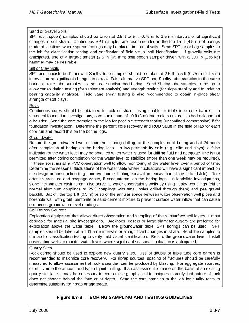
Sand or Gravel Soils SPT (split-spoon) samples should be taken at 2.5-ft to 5-ft (0.75-m to 1.5-m) intervals or at significant changes in soil strata. Continuous SPT samples are recommended in the top 15 ft (4.5 m) of borings made at locations where spread footings may be placed in natural soils. Send SPT jar or bag samples to the lab for classification testing and verification of field visual soil identification. If gravelly soils are anticipated, use of a large-diameter (2.5 in (65 mm) split spoon sampler driven with a 300 lb (136 kg) hammer may be desirable. Silt or Clay Soils SPT and “undisturbed” thin wall Shelby tube samples should be taken at 2.5-ft to 5-ft (0.75-m to 1.5-m) intervals or at significant changes in strata. Take alternative SPT and Shelby tube samples in the same boring or take tube samples in a separate undisturbed boring. Send Shelby tube samples to the lab to allow consolidation testing (for settlement analysis) and strength testing (for slope stability and foundation bearing capacity analysis). Field vane shear testing is also recommended to obtain in-place shear strength of soft clays. Rock Continuous cores should be obtained in rock or shales using double or triple tube core barrels. In structural foundation investigations, core a minimum of 10 ft (3 m) into rock to ensure it is bedrock and not a boulder. Send the core samples to the lab for possible strength testing (unconfined compression) if for foundation investigation. Determine the percent core recovery and RQD value in the field or lab for each core run and record this on the boring logs. Groundwater Record the groundwater level encountered during drilling, at the completion of boring and at 24 hours after completion of boring on the boring logs. In low-permeability soils (e.g., silts and clays), a false indication of the water level may be obtained when water is used for drilling fluid and adequate time is not permitted after boring completion for the water level to stabilize (more than one week may be required). In these soils, install a PVC observation well to allow monitoring of the water level over a period of time. Determine the seasonal fluctuations of the water table where fluctuations will have a significant impact on the design or construction (e.g., borrow source, footing excavation, excavation at toe of landslide). Note artesian pressure and seepage zones, if encountered, on the boring logs. In landslide investigations, slope inclinometer casings can also serve as water observations wells by using “leaky” couplings (either normal aluminum couplings or PVC couplings with small holes drilled through them) and pea gravel backfill. Backfill the top 1 ft (0.3 m) or so of the annular space between water observation well pipes and borehole wall with grout, bentonite or sand-cement mixture to prevent surface water inflow that can cause erroneous groundwater level readings. Soil Borrow Sources Exploration equipment that allows direct observation and sampling of the subsurface soil layers is most desirable for material site investigations. Backhoes, dozers or large diameter augers are preferred for exploration above the water table. Below the groundwater table, SPT borings can be used. SPT samples should be taken at 5-ft (1.5-m) intervals or at significant changes in strata. Send the samples to the lab for classification testing to verify field visual identification. Record the groundwater level. Install observation wells to monitor water levels where significant seasonal fluctuation is anticipated. Quarry Sites Rock coring should be used to explore new quarry sites. Use of double or triple tube core barrels is recommended to maximize core recovery. For riprap sources, spacing of fractures should be carefully measured to allow assessment of rock sizes that can be produced by blasting. For aggregate sources, carefully note the amount and type of joint infilling. If an assessment is made on the basis of an existing quarry site face, it may be necessary to core or use geophysical techniques to verify that nature of rock does not change behind the face or at depth. Send the core samples to the lab for quality tests to determine suitability for riprap or aggregate.
Figure 8.3-B ⎯ BORING SAMPLING AND TESTING GUIDELINES
MDT Geotechnical Manual Subsurface Investigations/Field Tests
8.3-8 July 2008
In cohesive soils, at least one undisturbed soil sample should be obtained from each different stratum encountered. If a uniform cohesive soil deposit extends for a considerable depth, additional undisturbed samples are commonly obtained at 10 ft (3 m) to 20 ft (6 m) intervals. Where borings are widely spaced, it may be appropriate to obtain undisturbed samples in each boring; however, for closely spaced borings, or in deposits that are generally uniform in lateral extent, undisturbed samples are commonly obtained only in selected borings. In erratic geologic formations or thin clay layers, it is sometimes necessary to drill a separate boring adjacent to a previously completed boring to obtain an undisturbed sample from a specific depth that may have been missed in the first boring or where an additional quantity of a sample is required for laboratory testing (e.g., where a CU triaxial test is anticipated).
8.3.5.3 Sample Numbering
The following information, where applicable, should be written on the top half of the tube or the top of the sample jar:
• uniform project number, • boring number, • depth interval, • blow counts, • percent recovery, and • sample date. Near the upper end of tube samples, include the word “top” and an arrow pointing toward the top of the sample. Putting sample information on both the tube/jar and the end cap facilitates retrieval of tubes/jars from laboratory storage and helps prevent mix-ups in the laboratory when several tubes/jars may have their end caps removed at the same time.
8.3.5.4 Transportation of Soil Samples
Each step in sampling, extruding, storing and testing introduces varying degrees of disturbance to the sample. Proper sampling, handling and storage methods are essential to minimize disturbances. The project geotechnical specialist must be cognizant of disturbance introduced during the various testing sampling steps. The Field Investigation Unit staff should also be sensitized about disturbance and the consequences.
A detailed discussion of sample preservation and transportation along with a recommended transportation container design is presented in ASTM D 4220. Transportation and storage of samples in Montana requires procedures that may not be required in other locations. Freezing temperatures can occur in some areas any day of the year. Shelby tube samples must be kept from freezing. This may include storing the tubes in a heated vehicle during the day while drilling in very cold conditions, storing tubes in a heated building at night and transporting tubes in the heated portion of a vehicle.
Travel distances to project sites can often require extensive travel on gravel surfaced roads or over rugged terrain for short distances. Do not store undisturbed samples in the back of trucks or other areas where they will be jarred extensively during travel. Ensure the samples are

MDT Geotechnical Manual Subsurface Investigations/Field Tests
July 2008 8.3-9
secure to prevent disturbance for transport of all Shelby tube samples. Place Shelby tube samples on a vibration absorbing material (e.g., foam, back seat of a vehicle) during transport. As practical, keep thin-walled tubes vertical with the top of the sample oriented in the up position. If available, keep thin-walled tubes in a carrier with an individual slot for each tube. Place padding below and between the tubes to cushion the tubes and to prevent them from striking one another. Secure the entire carrier with rope or cable to the body of the transporting vehicle so that the case will not tilt or tip over while the vehicle is in motion.
Undisturbed samples should not be stored in the Shelby tube for long periods of time, even when stored upright in a humidity room. As the storage duration increases, tubes tend to rust. This can alter the physical characteristics of the soil near the tube wall, and can result in changes in moisture content. Excessive pressure may be required to extrude the sample from the tube, and this pressure can alter the strength and compressibility of the soil. As a general guideline, Shelby tube samples stored more than several months normally should not be used for soil strength and compressibility testing. Samples that have been extruded from the Shelby tube should be set up immediately in the consolidation or triaxial systems. Do not allow extruded samples to be stored more than a few hours.
8.3.6 Sampling Methods (Rock)
8.3.6.1 Exploration and Investigation Methods
The methods used for exploration and investigation of rock samples include:
1. Drilling and Coring. Core drilling is the primary method used to obtain intact samples of rock for testing purposes and for assessing rock quality and structure. Borings resulting from rock coring are also used to obtain groundwater data, perform in-situ tests and install instruments.
2. Exploration Pits (Test Pits). Test pits can also be used to investigate the characteristics of weak or highly-fractured rock.
3. Geophysical Methods. Geophysical methods (e.g., seismic refraction, ground penetrating radar (GPR)) and may be used to obtain the depth to rock, elastic properties or for rippability assessment.
4. Geologic Mapping. Geologic mapping of rock exposures or outcrops provides a means for assessing the composition and discontinuities of rock strata on a large scale that may be valuable for many engineering applications particularly rock slope design
Review the FHWA Subsurface Investigation Manual for details on the types of rock samplers and sampling procedures available.
8.3.6.2 Transportation and Storage of Samples
Store rock cores from geotechnical explorations in structurally sound core boxes made of wood or corrugated waxed cardboard. Wooden boxes are preferred because they are stronger and
MDT Geotechnical Manual Subsurface Investigations/Field Tests
8.3-10 July 2008
can be reused and stacked on top of each other for transportation and storage. However, wooden boxes are more expensive and, for most applications, the cardboard box is acceptable.
Carefully handle the cores during transfer from barrel to box to preserve mating across fractures and fracture-filling materials. Breaks in core that occur during or after the core is transferred to the core box should be refitted and marked with three short parallel lines across the fracture trace to indicate a mechanical break. Also, mark the breaks made to fit the core into the core box and breaks made to examine an inner core surface. These deliberate breaks should be avoided unless absolutely necessary. Place the cores in the boxes from left to right, top to bottom. When the upper compartment of the box is filled, fill the next lower (or adjoining) compartment and so on, until the box is filled. Mark the depths of the top and bottom of the core and each noticeable gap in the formation with a clearly labeled, wooden-spacer block.
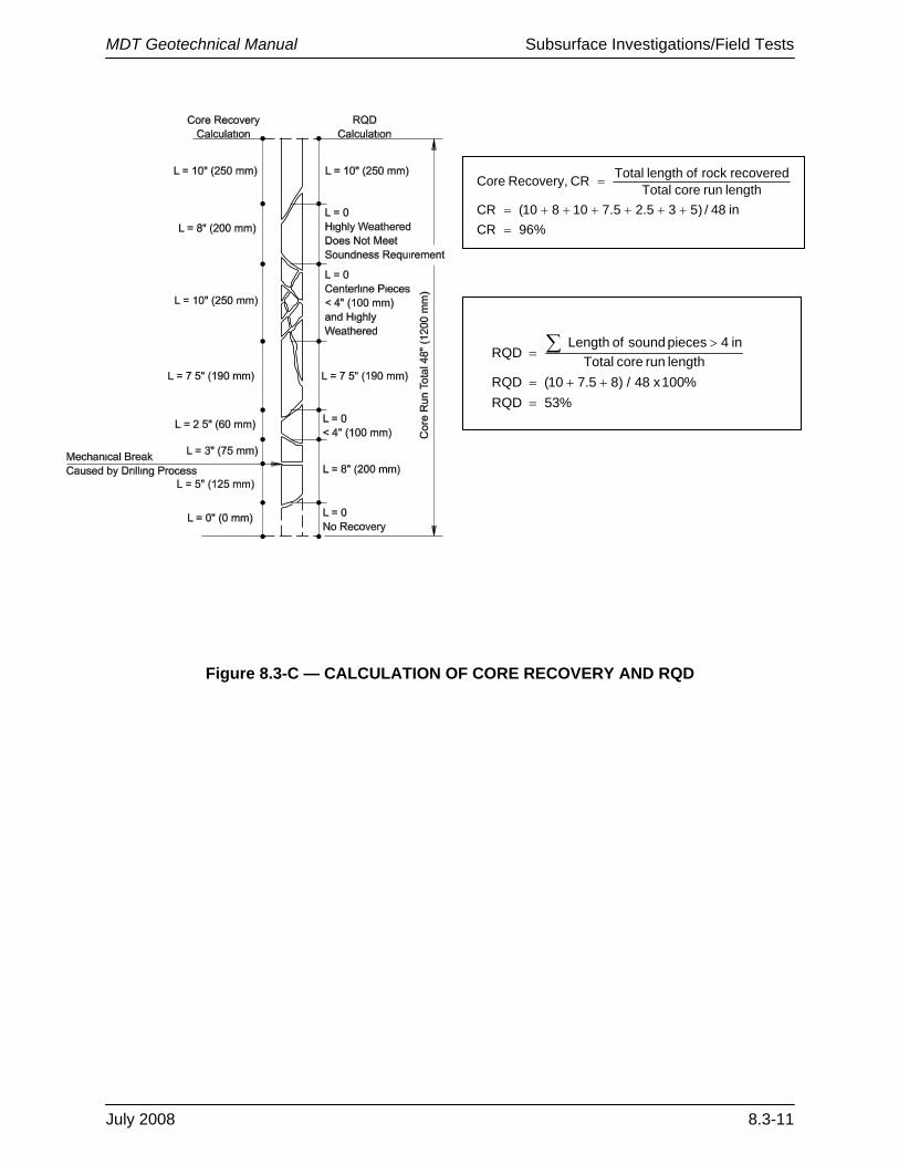
If there is less than 100% core recovery from a run, place a cardboard tube spacer of the same length as the core loss in the core box either at the depth of core loss, if known, or at the bottom of the run. Mark the depth of core loss, if known, or the length of core loss on the spacer with a black permanent marker. Calculate the percent core recovery and RQD in the field; see Figure 8.3-C for calculation guidance.
Prior to closing and sealing the box, take a picture of the cores in case there are breaks in the cores that occur during transportation (i.e., the breaks can be marked as noted above in the lab). For some projects or rock types, it may be desirable to wrap the core in a plastic to maintain the moisture within the core and to keep the pieces together in case there is a break during storage. If lab testing is planned on the sample, it may also be desirable to wrap sections to be tested with plastic wrap and then wax the section to preserve the moisture content of the sample.
Label the core box using an indelible black marking pen. The core box lid should have identical markings both inside and out. Both the exterior side and end of the box should identify the box number (Box # of ) and the information presented in Section 8.3.5.3. For angled borings, depths marked on core boxes and boring logs should be those measured along the axis of the boring. Note the angle and orientation of the boring on the core box and the boring logs.
8.3.7 Field Soil and Rock Classification
Soil description/identification is the systematic, precise and complete naming of individual soils in both written and spoken forms (ASTM D 2488, AASHTO M 145), while soil classification is the grouping of the soil with similar engineering properties into a category based on index test results (e.g., group name, symbol (ASTM D 2487, AASHTO M 145)). It is important to distinguish between visual identification and classification to minimize conflicts between general visual evaluations of soil samples in the field versus a more precise laboratory evaluation supported by index tests.
During progression of a boring, the field staff should only describe the soils encountered. Do not use group symbols associated with classifications in the field. Visual descriptions in the field are often subjected to outdoor elements that may influence results. It is important to send the soil samples to a laboratory for accurate visual identification by a technician experienced in soils work, as this single operation provides the basis for later testing and soil profile development.
MDT Geotechnical Manual Subsurface Investigations/Field Tests
July 2008 8.3-11
%96CRin48/)535.25.710810(CRlengthruncoreTotalrecoveredrockoflengthTotalCRRecovery,Core
=++++++=
=
%53RQD%100x48/)85.710(RQD
lengthruncoreTotalin4piecessoundofLength
RQD
=++=
>= ∑
Figure 8.3-C — CALCULATION OF CORE RECOVERY AND RQD
MDT Geotechnical Manual Subsurface Investigations/Field Tests
8.3-12 July 2008
Classification tests are performed by the Geotechnical Laboratory on representative samples to verify identification and assign appropriate group symbols. If possible, determine the moisture content on every cohesive sample and selected granular soils. For additional guidance on soil classification, see Chapter 9.
As with soil boring logs, rock or core boring logs should be as comprehensive as possible under field conditions, yet be terse and precise. The level of detail should be keyed to the purpose of the exploration as well as to the intended user of the prepared logs. Although the same basic information should be presented on all rock boring logs, the appropriate level of detail should be determined by the project geotechnical specialist based on project needs. Borings for a bridge foundation may require more detail concerning degree of weathering than rock structure features. For a proposed tunnel excavation, the opposite might be true. Extremely detailed descriptions of rock mineralogy may mask features significant to an engineer, but may be critical for a geologist.
8.3.8 Piezometers and Monitoring Well Installation
8.3.8.1 General
Observations of the groundwater level and pressure are an important part of all geotechnical explorations, and the identification of groundwater conditions should receive the same level of care given to soil descriptions and samples. Determination of groundwater levels and pressures includes measurements of the elevation of the groundwater surface or water table and its variation with the season of the year, the location of perched water tables, the location of aquifers and the presence of artesian pressures. Water levels and pressures may be measured in existing wells, boreholes and specially installed observation wells. Piezometers are used where the measurement of the groundwater pressures are specifically required (i.e., to determine excess hydrostatic pressures or the progress of primary consolidation).
Measurements of water level during drilling and at least once following drilling should be conducted to obtain the necessary groundwater data, unless alternative methods (e.g., installation of observation wells) are defined in the Subsurface Exploration Plan or by the project geotechnical specialist. Detailed guidance regarding groundwater observations can be obtained from ASTM D 4750 and ASTM D 5092.
8.3.8.2 Information from Existing Wells
Montana requires the drillers of water wells to file logs of the wells. These are good sources of information regarding the materials encountered and water levels recorded during previous well installations in an area of future development. The well owners, both public and private, may have records of the water levels after installation that may provide extensive information on fluctuations of the water level. This information is available from the Montana Department of Natural Resources and Conservation.
MDT Geotechnical Manual Subsurface Investigations/Field Tests
July 2008 8.3-13
8.3.8.3 Open Borings
The water level in open borings should be measured after any prolonged interruption in drilling, at the completion of each boring and, if practical, 24 hours after completion of drilling. Obtain additional water level measurements at the completion of the field exploration and other times designated by the project geotechnical specialist. Record the date and time of each observation.
If the borehole has caved, record the depth to the collapsed region. Describe this on the boring record as this may have been caused by groundwater conditions. The elevations of the caved depths of certain borings may be consistent with groundwater table elevations at the site. This may become apparent once the subsurface profile is constructed.
Drilling mud obscures observations of the groundwater level owing to filter cake action and the higher specific gravity of the drilling mud compared to that of the water. If drilling fluids are used to advance the borings, instruct the drilling crew to bail the hole prior to making groundwater observations. For some projects, consideration can be given to the use of biodegradable drilling muds.
8.3.8.4 Observation Wells and Piezometers
Observation wells and piezometers are used for measuring the groundwater locations at a site and for evaluating the performance of dewatering systems. In theory, a “piezometer” measures the pressure in a confined aquifer or at a specific horizon of the geologic profile, while an “observation well” measures the level in the geologic profile regardless of source or location. The term “monitoring well” also applies to wells that are periodically sampled for water quality. Monitoring wells are typically only used for environmental purposes. In practice, the terms piezometers, observation wells and monitoring wells are used interchangeably to describe any device for determining water elevation.
Details of typical observation well installations are provided in the FHWA Subsurface Investigation Manual. The simplest type of observation well is formed by a small-diameter polyvinyl chloride (PVC) pipe set in an open hole. The bottom of the pipe is slotted and capped, and the annular space around the slotted pipe is backfilled with clean sand. The area above the sand is sealed with bentonite, and the remaining annulus is filled with grout, concrete or soil cuttings. A surface seal, which is sloped away from the pipe, is commonly formed with concrete to prevent the entrance of surface water. The top of the pipe should be capped to prevent the entrance of foreign material; a small vent hole should also be placed in the top cap. In some localities, regulatory agencies may stipulate the manner for installation and closure of observation wells.
Driven or pushed-in well points are commonly used in granular soil formations and very soft clay. The well is formed by a stainless steel or brass well point threaded to a galvanized steel pipe. In granular soils, an open boring or rotary wash boring is advanced to a point several inches (millimeters) above the measurement depth and the well point is driven to the desired depth. A seal is commonly required in the boring above the well point with a surface seal at the ground surface. Note that observation wells may require development (see ASTM D 5092) to minimize the effects of installation, drilling fluids, etc. Minimum pipe diameters should allow

MDT Geotechnical Manual Subsurface Investigations/Field Tests
8.3-14 July 2008
introduction of a bailer or other pumping apparatus to remove fine-grained materials in the well to improve the response time.
Piezometers are available in a number of designs. The simplest design is no different than a monitoring well, though it may be smaller in diameter. However, the well screen is located to monitor the water head at a specific elevation. Geologic units above and below the screened depth are sealed with bentonite. Another alternative is to install a pneumatic or a vibrating wire pressure transducer at the elevation of interest. These transducers can be placed by drilling to the depth of interest or pushed to the depth after drilling to just above the depth, similar to the well points described above. These transducers can also be pushed from the ground surface in very soft soils.
8.3.8.5 Water Level Measurements
In general, common practice is to measure the depth to the water surface using the top of the casing as a reference, with the reference point at a common orientation (often North) marked or notched on the well casing. A number of devices have been developed for sensing or measuring the water level in observation wells (e.g., chalked tape, tape with a float, electrical water-level indicator, pressure transducers, data loggers). Additional guidance can be found in the FHWA Subsurface Investigation Manual.
8.3.8.6 Well Closure
Unless the soil is contaminated, the well can be filled with the original drillings. The common practice in Montana is to use bentonite chips for all well closures. For contaminated soils, coordinate the well closure with the Hazardous Waste Section in the Environmental Services Bureau.
After wells have been closed and sealed, the Field Supervisor must file a closure report with the Montana Department of Natural Resources and Conservation (DNRC).
8.3.8.7 Regulations
Drillers must be licensed by the DNRC to drill piezometers and monitoring wells. After installing a piezometer/monitoring well, the Field Supervisor must prepare and file a record with the DNRC. Note that observation wells must be removed in 30 days or less after their installation. Piezometer and monitoring wells may remain open for an indefinite time period.
Local jurisdictions may impose specific requirements on “permanent” monitoring wells, including closure and special reporting of the location and construction that must be considered in the planning and installation. Licensed drillers and special fees also may be required.

MDT Geotechnical Manual Subsurface Investigations/Field Tests
July 2008 8.3-15
8.3.9 Field/In-Situ Tests
8.3.9.1 General
The following sections describe both testing methods used by the Geotechnical Section and other common in-situ tests that might be used to address a specific project need. Figure 8.3-D identifies soil conditions where in-situ testing methods can be used to estimate engineering properties of the soils. These engineering properties range from shear strength to the stiffness of the soil or rock.
Type of Test Suitable For
Not Suitable For
Properties that can be Determined Remarks
Standard Penetration Test (SPT)*
Properties in cohesionless soils and samples of cohesive soil
Property determinations in soft to firm clays and in gravels
Empirical equations to estimate relative density, friction angle, shear wave velocity, and liquefaction potential
See Section 8.3.9.3
Field Vane Shear Test (FVT)*
Undrained strength in cohesive soils
Sand and Gravel
Undrained shear strength.
See Section 8.3.9.4. Test should be used with care, particularly in fissured, varved and highly plastic clays.
Cone Penetration Test (CPT)*
Sand, silt and clay Gravel
Continuous evaluation of penetration resistance of sands, silts and clays. Results can be used to estimate soil type, friction characteristics of sands, and undrained shear strength in clays
See Section 8.3.9.5. Test is best suited for the design of footings and piles in sand; tests in clay are more reliable when used in conjunction with vane tests.
Pressuremeter Test (PMT)
Soft rock, dense sand, silts, clays
Soft sensitive clays, loose silts and sands
Compressibility (modulus value) and coefficient of earth pressure at rest
Iowa Borehole Shear Test
Sands, silts, and clays
Gravels and rock
Friction angle of sand, undrained strength of clays
Dilatometer Test (DMT)
Sand and Clay Gravel
Empirical correlation for soil type, coefficient of earth pressure for at rest conditions (Ko), over consolidation ratio, undrained shear strength and modulus
*Currently used by MDT.
Figure 8.3-D ⎯ SUMMARY OF COMMON IN-SITU TESTS
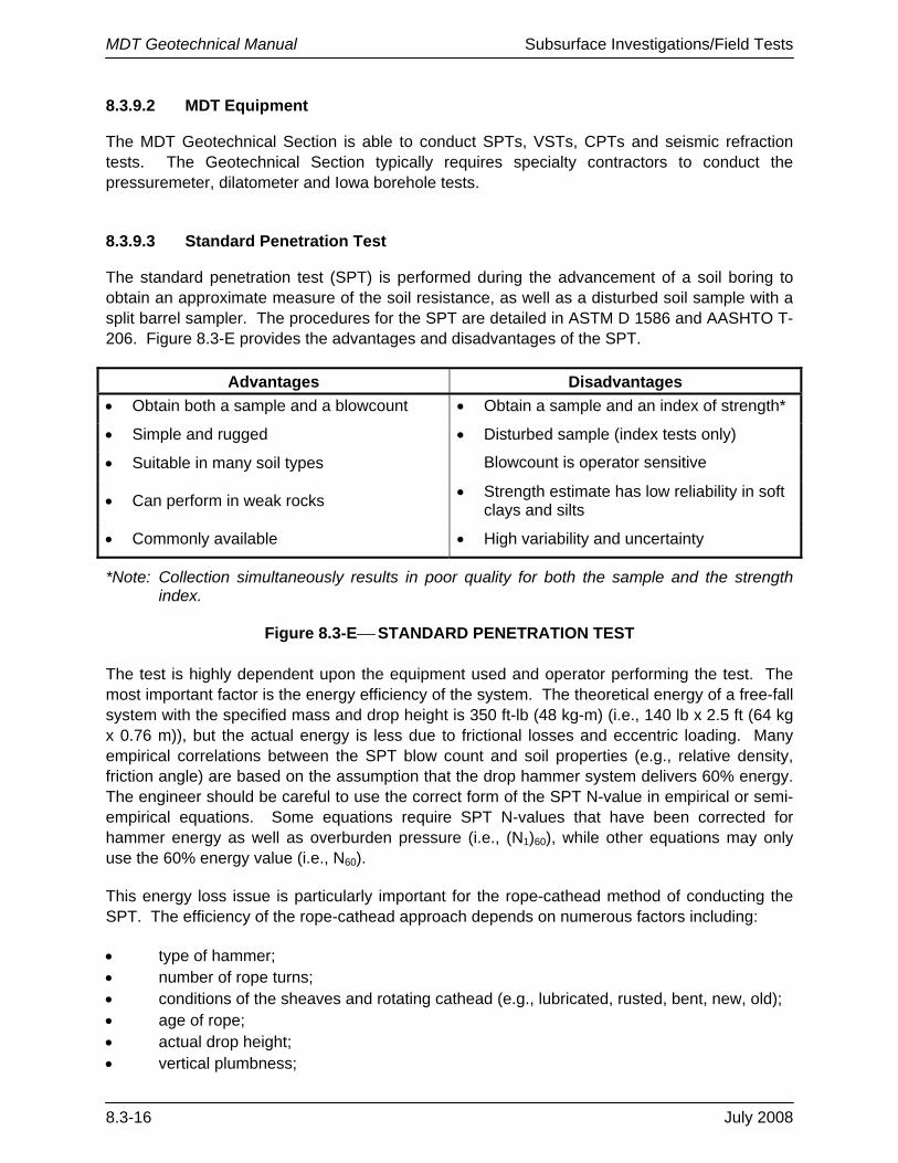
MDT Geotechnical Manual Subsurface Investigations/Field Tests
8.3-16 July 2008
8.3.9.2 MDT Equipment
The MDT Geotechnical Section is able to conduct SPTs, VSTs, CPTs and seismic refraction tests. The Geotechnical Section typically requires specialty contractors to conduct the pressuremeter, dilatometer and Iowa borehole tests.
8.3.9.3 Standard Penetration Test
The standard penetration test (SPT) is performed during the advancement of a soil boring to obtain an approximate measure of the soil resistance, as well as a disturbed soil sample with a split barrel sampler. The procedures for the SPT are detailed in ASTM D 1586 and AASHTO T-206. Figure 8.3-E provides the advantages and disadvantages of the SPT.
Advantages Disadvantages • Obtain both a sample and a blowcount • Obtain a sample and an index of strength*
• Simple and rugged • Disturbed sample (index tests only)
• Suitable in many soil types Blowcount is operator sensitive
• Can perform in weak rocks • Strength estimate has low reliability in soft clays and silts
• Commonly available • High variability and uncertainty
*Note: Collection simultaneously results in poor quality for both the sample and the strength index.
Figure 8.3-E⎯ STANDARD PENETRATION TEST The test is highly dependent upon the equipment used and operator performing the test. The most important factor is the energy efficiency of the system. The theoretical energy of a free-fall system with the specified mass and drop height is 350 ft-lb (48 kg-m) (i.e., 140 lb x 2.5 ft (64 kg x 0.76 m)), but the actual energy is less due to frictional losses and eccentric loading. Many empirical correlations between the SPT blow count and soil properties (e.g., relative density, friction angle) are based on the assumption that the drop hammer system delivers 60% energy. The engineer should be careful to use the correct form of the SPT N-value in empirical or semi-empirical equations. Some equations require SPT N-values that have been corrected for hammer energy as well as overburden pressure (i.e., (N1)60), while other equations may only use the 60% energy value (i.e., N60).
This energy loss issue is particularly important for the rope-cathead method of conducting the SPT. The efficiency of the rope-cathead approach depends on numerous factors including:
• type of hammer; • number of rope turns; • conditions of the sheaves and rotating cathead (e.g., lubricated, rusted, bent, new, old); • age of rope; • actual drop height; • vertical plumbness;

MDT Geotechnical Manual Subsurface Investigations/Field Tests
July 2008 8.3-17
• weather and moisture conditions (e.g., wet, dry, freezing); and • other variables. Automatic systems for lifting and dropping the mass minimize these factors, resulting in a higher delivered energy and a more consistent blowcount. Wherever possible, use the automatic hammer systems to conduct the SPTs.
Because of the importance of system efficiency, periodic calibration of the specific drill rig and operator using the hammer delivery system is required for all geotechnical work performed on MDT projects. Hammer systems on drilling equipment used by MDT, consultants or contractor drilling equipment must be calibrated for energy efficiency to quantify the actual efficiency of the given hammer system. ASTM D 4633 provides guidance on calibration of energy efficiency using instrumented strain gages and accelerometer measurements in order to better standardize the energy levels. Rope-cathead systems have been found to have energy levels from about 35% to 85% using donut or safety hammers. Automatic hammers can deliver between 80% to 90% efficiency depending on the system used.
8.3.9.4 Vane Shear Test
The vane shear test (VST), or field vane (FV), is used to evaluate the in-place, undrained shear strength (suv) of soft to stiff clays and silts. The test consists of inserting a 4-bladed vane into the clay and rotating the device about a vertical axis, per ASTM D 2573 guidelines.
Limit equilibrium analysis is used to relate the measured peak torque to the calculated value of su. Both the peak and remolded strengths can be measured; their ratio is termed the sensitivity (St). A selection of vanes is available in terms of size, shape and configuration, depending upon the consistency and strength characteristics of the soil. The standard vane has a rectangular geometry with a blade diameter (D) equal to 50% of the vane height. Typical diameters range from 1 in to 2 in (25 mm to 50 mm).
Figure 8.3-F provides the advantages and disadvantages of vane shear test. It is very important that the measured vane strength be corrected prior to use in embankment stability, bearing capacity and excavations in soft clays.
Advantages Disadvantages
• Assessment of undrained strength (suv) • Limited application to soft to stiff clays
• Simple test and equipment • Slow and time consuming
• Measure in-situ clay sensitivity (St) • Raw suv needs (empirical) correction
• Long history of use in practice • Can be affected by sand lenses and seams
Figure 8.3-F ⎯ VANE SHEAR TEST

MDT Geotechnical Manual Subsurface Investigations/Field Tests
8.3-18 July 2008
8.3.9.5 Cone Penetration Test (CPT)
8.3.9.5.1 General
The cone penetration test is fast, economical and provides continuous profiling of geostratigraphy and soil properties evaluation. Both mechanical and electric cone systems are available; however, for most modern-day investigations the electric cone system is used.
MDT recently acquired an electric cone system for use on its projects. At one time, MDT used a mechanical CPT system and project archives contain records from these tests. However, for projects where CPTs will be performed, including those carried out by subcontractors, MDT requires use of the electric CPT.
The test is performed according to ASTM D 5778 (electric and electronic systems) and consists of pushing a cylindrical steel probe into the ground at a constant rate of approximately 0.8 in/s (20 mm/s) and measuring resistance to penetration. The standard penetrometer has a conical tip with 60° angle apex, 1.4-in (35.7-mm) diameter body 1.55-in2 (10-cm2) projected area), and a 23-in2 (150-cm2) friction sleeve. The measured point or tip resistance is designated qc and the measured side or sleeve resistance is fs. The ASTM standard also permits use of a larger cone.
The CPT can be used in very soft clays to dense sands, but is not appropriate for gravels or rock terrain. The advantages and disadvantages of the CPT are listed in Figure 8.3-G. As the test provides more accurate and reliable numbers for analysis with no soil sampling, it provides an excellent complement to the more conventional soil test boring with SPT measurements.
8.3.9.5.2 Piezocones and Seismic Cones
Piezocones (CPTu) are cone penetrometers with added transducers to measure penetration porewater pressures during the advancement of the probe. The following apply:
1. Clean Sands. The measured pore pressures during penetration will depend on the density of the sand – with pore pressures being either above or below hydrostatic depending on whether the sand contracts or dilates during shear. When the penetration is stopped, the pore pressures will normally change to hydrostatic because the high permeability of the sand permits immediate equilibration of porewater pressures.
Advantages Disadvantages
• Fast and continuous profile • High capital investment
• Economical and productive • Requires skilled operator to run
• Results not operator dependent* • Electronic drift, noise and calibration
• Strong theoretical basis in interpretation • No soil samples are obtained
• Particularly suitable for soft soils • Unsuitable for gravel or granular deposits*
*Note: Except where special rigs are provided and/or additional drilling support is available.
Figure 8.3-G ⎯ CONE PENETRATION TEST
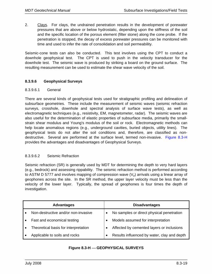
MDT Geotechnical Manual Subsurface Investigations/Field Tests
July 2008 8.3-19
2. Clays. For clays, the undrained penetration results in the development of porewater pressures that are above or below hydrostatic, depending upon the stiffness of the soil and the specific location of the porous element (filter stone) along the cone probe. If the penetration is stopped, the decay of excess porewater pressures can be monitored with time and used to infer the rate of consolidation and soil permeability.
Seismic-cone tests can also be conducted. This test involves using the CPT to conduct a downhole geophysical test. The CPT is used to push in the velocity transducer for the downhole test. The seismic wave is produced by striking a board on the ground surface. The resulting measurement can be used to estimate the shear wave velocity of the soil.
8.3.9.6 Geophysical Surveys
8.3.9.6.1 General
There are several kinds of geophysical tests used for stratigraphic profiling and delineation of subsurface geometries. These include the measurement of seismic waves (seismic refraction surveys, crosshole, downhole and spectral analysis of surface wave tests), as well as electromagnetic techniques (e.g., resistivity, EM, magnetometer, radar). The seismic waves are also useful for the determination of elastic properties of subsurface media, primarily the small-strain shear modulus and Young's modulus of the soil or rock. Electromagnetic methods can help locate anomalous regions (e.g., underground cavities, buried objects, utility lines). The geophysical tests do not alter the soil conditions and, therefore, are classified as non-destructive. Several are performed at the surface level, termed non-invasive. Figure 8.3-H provides the advantages and disadvantages of Geophysical Surveys.
8.3.9.6.2 Seismic Refraction
Seismic refraction (SR) is generally used by MDT for determining the depth to very hard layers (e.g., bedrock) and assessing rippability. The seismic refraction method is performed according to ASTM D 5777 and involves mapping of compression wave (Vp) arrivals using a linear array of geophones across the site. In the SR method, the upper layer velocity must be less than the velocity of the lower layer. Typically, the spread of geophones is four times the depth of investigation.
Advantages Disadvantages
• Non-destructive and/or non-invasive • No samples or direct physical penetration
• Fast and economical testing • Models assumed for interpretation
• Theoretical basis for interpretation • Affected by cemented layers or inclusions
• Applicable to soils and rocks • Results influenced by water, clay and depth
Figure 8.3-H ⎯ GEOPHYSICAL SURVEYS

MDT Geotechnical Manual Subsurface Investigations/Field Tests
8.3-20 July 2008
Results of SR surveys are used in the calculation of depth to major soil layers, water table and rock. The SR data can also be useful to determine the degree of rippability of different rock materials using heavy construction equipment. With improved electronics, the shear wave profiles may also be determined by SR.
8.3.9.7 Other Testing Methods
Other testing methods are available that are conducted by specialty contractors. Guidance on Seismic Wave Surveys, Crosshole Tests (CHT), Downhole Tests (DHT) and Ground Penetrating Radar Surveys can found in the 2003 FHWA Manual Application of Geophysical Methods to Highway Related Problems (FHWA-DTFH68-02-P-003). Guidance on the Flat Plate Dilatometer Test (DMT), Pressuremeter Test (PMT) and Iowa Borehole Shear Test (BST) can be found in the FHWA Subsurface Investigations Manual. The decision on when to use these test will be determined on a case-by-case basis by the project geotechnical specialist.
8.3.10 Borehole Completion and Site Restoration
All borings should be properly closed at the completion of the field exploration. This is typically required for safety considerations and to prevent cross contamination of soil strata and groundwater. The Field Investigation Unit staff will be responsible for the following:
1. Property Cleanup. As practical, the site should be returned to its original conditions. For sensitive conditions, take before and after pictures to address possible complaints from the landowner.
2. Backfill. Consider the following:
a. Unless the soil is contaminated, backfill and compact the borehole with the borehole cuttings.
b. In pavements, backfill the borehole with the cuttings. Compact from 6 in (150 mm) below the pavement surface to a depth of 18 to 24 in (450 mm to 600 mm) by tamping the backfill. Fill the top 6 in (150 mm) with quick-curing concrete or asphalt patch, depending upon the pavement type.
c. Patch boreholes on bridge decks with quick-curing concrete. If Bridge Maintenance personnel are unavailable, the Field Investigation Unit staff will be responsible for repair of the bridge deck.
d. Certain borings in dams and landslides may require to be filled with grout to prevent water infiltration.
3. Observation Wells. Well closure requirements are discussed in Section 8.3.8.6.
4. District Maintenance. If significant site damage was done within the right-of-way (e.g., rutting) or there is need to remove the access point, the project geotechnical specialist may request District Maintenance to repair the damage.

MDT Geotechnical Manual Subsurface Investigations/Field Tests
July 2008 8.4-1
8.4 POST FIELD WORK
8.4.1 Boring Log Preparation
The boring log is the basic record of the geotechnical exploration and provides a detailed record of the work performed and findings of the investigation. All portions of the field logs should be completed in the field prior to completion of the field exploration.
The Geotechnical Section has for its in-house staff a reference manual for logging borings that includes boring log formats, a log key, ASTM/AASHTO classifications and other information that should be included on the final boring log. Information from the field boring logs is entered directly into the computer program gINT to produce the final boring log. Consultants should review the FHWA Subsurface Investigations for guidance on preparing boring logs.
Once the borehole log is completed, copies of the log will be reviewed by at least one other project geotechnical specialist. This review will be performed for quality assurance purposes (e.g., completeness of the information being presented, consistency with Department criteria and preferences, reasonableness relative to expected conditions at the project site).
8.4.2 Lab Tests
The staff in the Geotechnical and Materials Laboratory will conduct various tests on the samples received from the field (e.g., moisture content, plastic limit, liquid limit, soil strength). These tests are discussed in Chapter 9. This information is included on the final boring logs.
If results of laboratory classification tests indicate that the soil or rock classification made in the field need to be changed, the project geotechnical specialist will be responsible for making these changes.
8.4.3 Reports
In addition to the boring logs, the following information may be included in the Geotechnical Report and memorandum or email sent to the project designer (e.g., Bridge, Road Design, Traffic):
• boring plan maps, • CPT data (table or graphical form), • geophysical data, • long-term groundwater monitoring results, and/or • other long-term instrumentation data results. Chapter 5 provides guidance on what information should be included in the final Geotechnical Report and how this information should be presented.

MDT Geotechnical Manual Subsurface Investigations/Field Tests
8.4-2 July 2008