traxall 700 series user manual 89-09-0031 … arrows point out ... rate of each color-coded cdi...
TRANSCRIPT

on and Tracking SystemModels 770 & 720
USER GUIDE
TRAXALL
1575 - 90 Ave Edmonton, AB Canada T6P 0E2Ph: 780.416.4850 | Fax: 780.416.4829 | apachepipe.com | Email: [email protected]
world class world wide

TRAXALL 700 SERIES USER GUIDE
Page 2 of 72
Informa� on in this document is subject to change without no� ce and applies only to the version of so� ware, hardware, or � rmware described on the � tle page.
The so� ware, hardware, and � rmware described in this document are designed, manufactured, and wri� en by CDI. The so� ware and � rmware copyright © 2014 CDI with all rights reserved.
This document © 2014 CDI. All rights reserved.Document Number 89-09-0031-00Manual Revision 1.06 29 AUG 2014
TRAXALL, TRAXALL Remote Control, FieldLink, and Con� gurator products are covered under United States Patents
Microso� and Windows are U.S. registered trademarks of Microso� Corpora� on.
Google Earth is a service of Google Inc.
Adobe, the Adobe logo, Acrobat, and Reader are either registered trademarks or trademarks of Adobe Systems Incorporated in the United States and/or other countries.
TRAXALL 700 SERIES USER GUIDE
Page 3 of 72
CONTENTS
ABOUT THIS USER GUIDE ...................................................................... 4Conven� ons used in this publica� on ...................................................... 4
OVERVIEW ............................................................................................... 5Features and Capabili� es ........................................................................ 5Devices Supported by TRAXALL .............................................................. 6Components ........................................................................................... 8Controls .................................................................................................. 9I/O Connec� ons .................................................................................... 11LCD Display ........................................................................................... 12
GETTING STARTED .................................................................................. 17
OPERATION ........................................................................................... 19Passage Detec� on ................................................................................. 19Playback ............................................................................................... 24Pinpoin� ng ............................................................................................ 31
APPENDIX .............................................................................................. 38System Menu Tree ................................................................................ 38Global Posi� oning System (GPS) ........................................................... 45Remote Opera� on ................................................................................ 53
OPTIONAL EQUIPMENT ....................................................................... 68TRAXALL Linestat .................................................................................. 68
WARRANTY ............................................................................................ 70
CARE, MAINTENANCE, & SERVICING .................................................. 71
ABOUT CDI ............................................................................................ 72

TRAXALL 700 SERIES USER GUIDE
Page 4 of 72
ABOUT THIS USER GUIDE
Conven� ons used in this publica� on
�� � � and � indicate you are to press Up, Down, Right, Le� , or Enter on the keypad (pg. 10):
Menu op� ons will appear in this guide exactly as displayed. For example, “REC PASSES” and “SEL VISIBLE DATA” refer to Record Passages and Select Visible Data op� ons.
Solid arrows indicate sequence, progression, or transi� on:
Outlined arrows point out speci� c items or details:
Segmented arrows indicate physical movement:
TRAXALL 700 SERIES USER GUIDE
Page 5 of 72
OVERVIEW FEATURES
OVERVIEW
Features and Capabili� es
TRAXALL is CDI’s latest and most powerful pig loca� ng and tracking receiver.
This formidable array of tracking and loca� ng technologies is complemented by a large number of useful new features:
• Mul� -frequency* transmi� er, “Legacy” (22Hz) transmi� er, and Magne� c-� ux leakage (MFL) “smart pig” detec� on capability • Three viewing modes • Pinpointer® precision locator • Built-in Global Posi� oning Satellite receiver • Built-in Bluetooth® for remote communica� on • Programmable relays • USB port
These features will be explained as you read through the GETTING STARTED and OPERATION sec� ons of this user guide. Details can be found in the APPENDIX (pg. 38).
* TRAXALL 770 and 720 are iden� cal in design, func� on, and opera� on, di� ering only in mul� -frequency capability. The 720 can iden� fy and record two transmi� er frequencies simultaneously, the 770 can process as many as seven.
Because of the similarity of the two models, this User Guide will generally refer to and show the TRAXALL 770.

TRAXALL 700 SERIES USER GUIDE
Page 6 of 72
OVERVIEW
Devices Supported by TRAXALL
Mul� -frequency Transmi� ers
The TRAXALL 770 can separate, iden� fy, and record as many as seven transmi� er frequencies* simultaneously. Transmission pulse rate of each color-coded CDI X-Series transmi� er can be customized with CDI’s special FieldLink Con� gurator applica� on.
* TRAXALL 720: two frequencies
Single-frequency (“Legacy”) Transmi� ers
CDI T-series single-frequency (21.768 Hz) transmi� ers are available in various sizes, pressure ranges, and pulse rates.
e es
DEVICES

TRAXALL 700 SERIES USER GUIDE
Page 7 of 72
OVERVIEW
MAGNETIC POLES MAGNETIC POLESDETECTOR
ODOMETER WHEELS DATA RECORDER
Magne� c Flux Leakage (MFL) Pigs
Magne� c Flux Leakage is a form of nondestruc� ve inline inspec� on that detects corrosion, pi� ng, missing metal, cracks, and/or other defects in steel pipelines.
An MFL “smart pig” such as shown here is a common inline inspec� on tool:
As it travels through a pipeline, the magne� c array magne� zes the steel. When defects are encountered, the magne� c � eld "leaks" from the steel. This leakage � eld is sensed by the magne� c detector.
Field intensity and defect loca� ons are usually stored by the unit’s on-board recorder.
Inline Inspec� on (ILI) Tool Transmi� ers
ILI transmi� ers are similar in performance and func� on to the T-series transmi� ers, but in lieu of pressure housings, are designed to work in conjunc� on with MFL pigs.
DEVICES

TRAXALL 700 SERIES USER GUIDE
Page 8 of 72
OVERVIEW
Components
The Pipe Alignment legend is a guide to help you posi� on your TRAXALL receiver for best
passage detec� on results.
MFL & TRANSMITTER SENSOR ANTENNAS
LCD DISPLAY
CONTROLS
HANDLE
SHOULDERSTRAP
BATTERYCOMPARTMENT
PINPOINTSENSOR
PIPE ALIGNMENT LEGEND
COMPONENTS

TRAXALL 700 SERIES USER GUIDE
Page 9 of 72
OVERVIEW
The handle and shoulder strap support the TRAXALL receiver during portable tracking/searching opera� on, such as “walking the line” during Pinpoin� ng (pg. 31).
ControlsPower ON/OFF
COMPONENTS/CONTROLS
POWERON/OFF
AUTOMATICLIGHT SENSOR
RELAY PORTFOR SATELLITE RADIO& RELAY CONTACTS
USB/BLUETOOTHCONNECTION
KEYPAD

TRAXALL 700 SERIES USER GUIDE
Page 10 of 72
OVERVIEW
Depress bu� on for 3–5 seconds to power up the TRAXALL receiver (same to power down).
Automa� c Light Sensor (ALS)
The ALS will automa� cally adjust LCD backligh� ng brightness for op� mal visibility and ba� ery life. Backligh� ng can also be adjusted manually via the SYSTEM menu.
Keypad
The keypad is where TRAXALL controls are accessed.Use the
Up �
Down �
Right �
Le� ��
and Enter � keys to cycle through the mode and menu op� ons.
CONTROLS
menu op�ons

TRAXALL 700 SERIES USER GUIDE
Page 11 of 72
OVERVIEW
I/O Connec� ons
Relay Port
A 12-pin connector provides CDI LineStat satellite radio connec� on, I/O, and programmable relay contacts which are programmable to varying pa� erns.
USB
When connected to a laptop or PC, TRAXALL will register as a mass storage device on the host PC.
During connec� on, the TRAXALL will display a screen that says ‘Syncing’. All other TRAXALL func� onality is o� during the PC USB connec� on.
Bluetooth
TRAXALL’S built-in Bluetooth will let you monitor and operate your TRAXALL receiver from a remote loca� on (for example, a vehicle cab or shelter during inclement weather) on a laptop or PC over an approximate maximum distance of 330 � (100 m).
I/O CONNECTIONS
Page 11 of 72

TRAXALL 700 SERIES USER GUIDE
Page 12 of 72
OVERVIEW
LCD Display
History Window
This is where tracking informa� on and system menus are displayed.
Source Legend
This is a decal to help you iden� fy signal source displayed in the History Window.
1–7: TRAXALL X-Series transmi� ers, color-coded across seven di� erent frequencies (two for the TRAXALL 720 model)
Legacy: Tradi� onal CDI CD42 T-Series single-frequency (22Hz) transmi� ers
Mag: used to detect a magne� c � ux leakage(MFL) “smart pig”
LCD DISPLAY
PINPOINTERDIAL
BATTERY STRENGTHINDICATOR
GPSDIAL
BLUETOOTHENABLED/DISABLEDINDICATOR
GAIN STRENGTHINDICATOR
SOURCELEGEND
GAINCONTROL
FILL MODESELECTOR
SYSTEMMENU
GPSMENU
HELPMENU
HISTORY WINDOW
akage
eeed
TRAXALL 700 SERIES USER GUIDE
Page 13 of 72
OVERVIEW
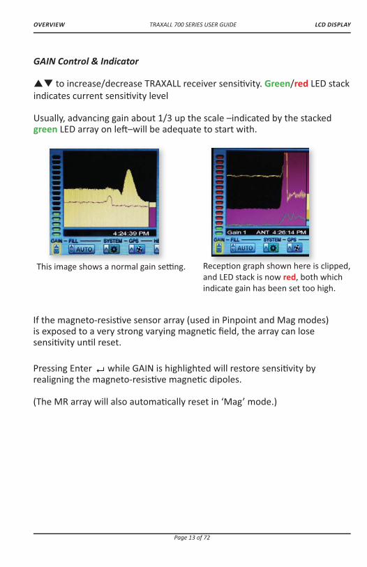
GAIN Control & Indicator
�� to increase/decrease TRAXALL receiver sensi� vity. Green/red LED stack indicates current sensi� vity level
Usually, advancing gain about 1/3 up the scale –indicated by the stacked green LED array on le� –will be adequate to start with.
LCD DISPLAY
Recep� on graph shown here is clipped, and LED stack is now red, both which indicate gain has been set too high.
This image shows a normal gain se� ng. � h h h i
If the magneto-resis� ve sensor array (used in Pinpoint and Mag modes) is exposed to a very strong varying magne� c � eld, the array can lose sensi� vity un� l reset.
Pressing Enter � while GAIN is highlighted will restore sensi� vity by realigning the magneto-resis� ve magne� c dipoles.
(The MR array will also automa� cally reset in ‘Mag’ mode.)
TRAXALL 700 SERIES USER GUIDE
Page 14 of 72
OVERVIEW
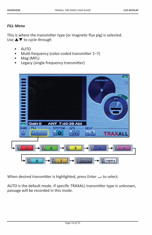
FILL Menu
This is where the transmi� er type (or magne� c � ux pig) is selected. Use �� to cycle through • AUTO • Mul� -frequency (color-coded transmi� er 1–7) • Mag (MFL) • Legacy (single-frequency transmi� er)
When desired transmi� er is highlighted, press Enter � to select.
AUTO is the default mode. If speci� c TRAXALL transmi� er type is unknown, passage will be recorded in this mode.
LCD DISPLAY
TRAXALL 700 SERIES USER GUIDE
Page 15 of 72
OVERVIEW
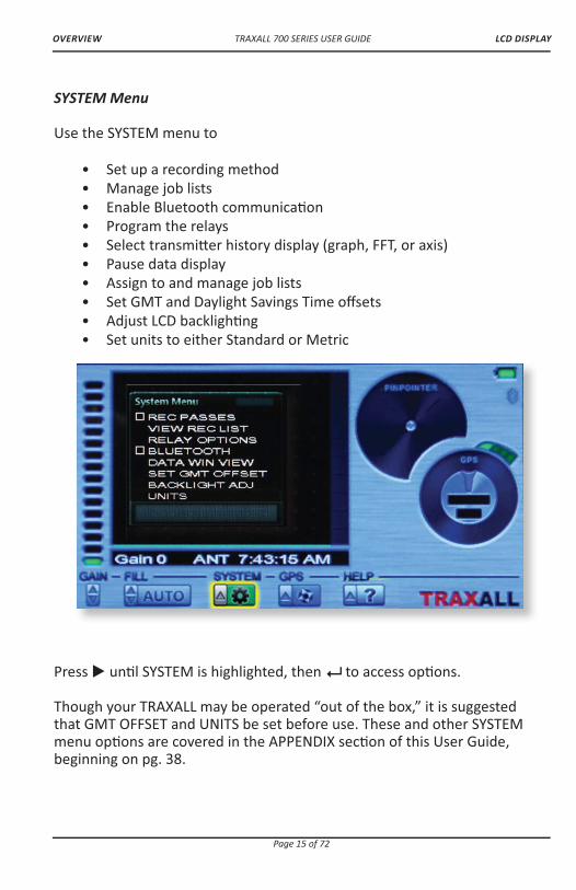
SYSTEM Menu
Use the SYSTEM menu to
• Set up a recording method • Manage job lists • Enable Bluetooth communica� on • Program the relays • Select transmi� er history display (graph, FFT, or axis) • Pause data display • Assign to and manage job lists • Set GMT and Daylight Savings Time o� sets • Adjust LCD backligh� ng • Set units to either Standard or Metric
Press � un� l SYSTEM is highlighted, then ��to access op� ons.
Though your TRAXALL may be operated “out of the box,” it is suggested that GMT OFFSET and UNITS be set before use. These and other SYSTEM menu op� ons are covered in the APPENDIX sec� on of this User Guide, beginning on pg. 38.
LCD DISPLAY
TRAXALL 700 SERIES USER GUIDE
Page 16 of 72
OVERVIEW
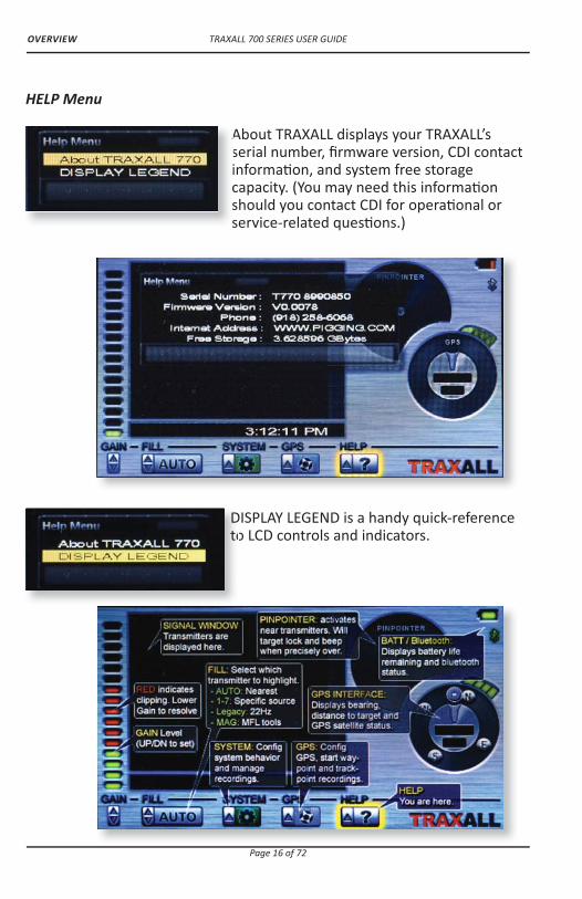
DISPLAY LEGEND is a handy quick-reference to LCD controls and indicators.
HELP Menu
About TRAXALL displays your TRAXALL’s serial number, � rmware version, CDI contact informa� on, and system free storage capacity. (You may need this informa� on should you contact CDI for opera� onal or service-related ques� ons.)
Asicss
Dto

TRAXALL 700 SERIES USER GUIDE
Page 17 of 72
GETTING STARTED
GETTING STARTED
Unpacking
The TRAXALL is shipped preassembled. It is only necessary to insert the ba� eries (included).
Ba� eries
Open the TRAXALL ba� ery compartment. A screwdriver is included for this purpose.
D-cell ba� eries are also included. Insert six–posi� ve side to red contacts–as shown here.
UNPACKING/BATTERIES

TRAXALL 700 SERIES USER GUIDE
Page 18 of 72
GETTING STARTED
Close the compartment. Make sure screws are � rmly seated to maintain a weatherproof seal.
Startup
Hold down the Power bu� on about 3–5 seconds.
TRAXALL � rmware and serial number will momentarily appear. (This informa� on is also available in the HELP menu. See pg. 16.)
STARTUP

TRAXALL 700 SERIES USER GUIDE
Page 19 of 72
OPERATION
OPERATION
Passage Detec� on
Using your TRAXALL to detect and record data for a moving pig.
Align the TRAXALL along pipeline as shown.
TRACKING

TRAXALL 700 SERIES USER GUIDE
Page 20 of 72
OPERATION
Record mode and job assignment
You may monitor in real � me, record, or monitor ��� record depending on how you con� gure the REC PASSES op� ons in the SYSTEM menu.
From the SYSTEM menu
To record:
- Access the SYSTEM menu.
- Press��when REC PASSES is highlighted (box default is unchecked).
- Use � to select Job 1 through 5 from the SYSTEM Job List menu
- Select either AUTO TRIGGER* or MANUAL.
REC PASSES box will be checked and you will be ready to record. (If REC PASSES box is checked and you do not want to record, simply� to uncheck.)
*NOTE: Place TRAXALL in posi� on before selec� ng AUTO TRIGGER.
From the SYSTEM menu
TRACKING
TRAXALL 700 SERIES USER GUIDE
Page 21 of 72
OPERATION
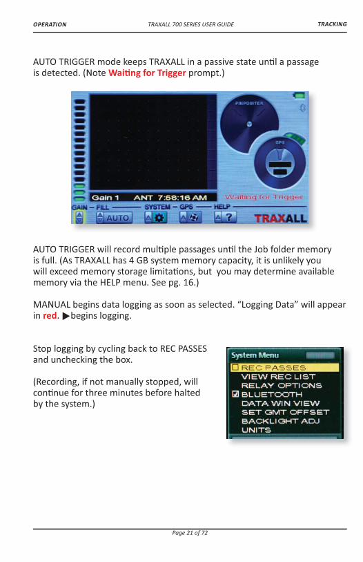
AUTO TRIGGER mode keeps TRAXALL in a passive state un� l a passage is detected. (Note Wai� ng for Trigger prompt.)
AUTO TRIGGER will record mul� ple passages un� l the Job folder memory is full. (As TRAXALL has 4 GB system memory capacity, it is unlikely you will exceed memory storage limita� ons, but you may determine available memory via the HELP menu. See pg. 16.)
MANUAL begins data logging as soon as selected. “Logging Data” will appear in red. �begins logging.
Stop logging by cycling back to REC PASSESand unchecking the box.
(Recording, if not manually stopped, will con� nue for three minutes before halted by the system.)
TRACKING

TRAXALL 700 SERIES USER GUIDE
Page 22 of 72
OPERATION
Tracking Example 1
Here are some typical tracking applica� ons:
SETTINGS:
Transmi� er: CDI X100 Fill se� ng: AUTO Record mode: AUTO TRIGGER
Once se� ngs are entered, your TRAXALL is ready to record a passage.
TRACKING

TRAXALL 700 SERIES USER GUIDE
Page 23 of 72
OPERATION
Wai� ng for Trigger
As you are in AUTO TRIGGER, TRAXALL will remain in a wait-state un� l a pig transmi� er reaches the sensor
Verifying Passage
The pig has passed through this loca� on, and TRAXALL is now verifying and logging passage
Passage Logged
TRAXALL is wri� ng passage informa� on to the Job 1 folder of system memory. (You may review this passage at any � me via VIEW REC LIST menu.) TRAXALL is ready for the next passage.
TRACKING
TRAXALL 700 SERIES USER GUIDE
Page 24 of 72
OPERATION
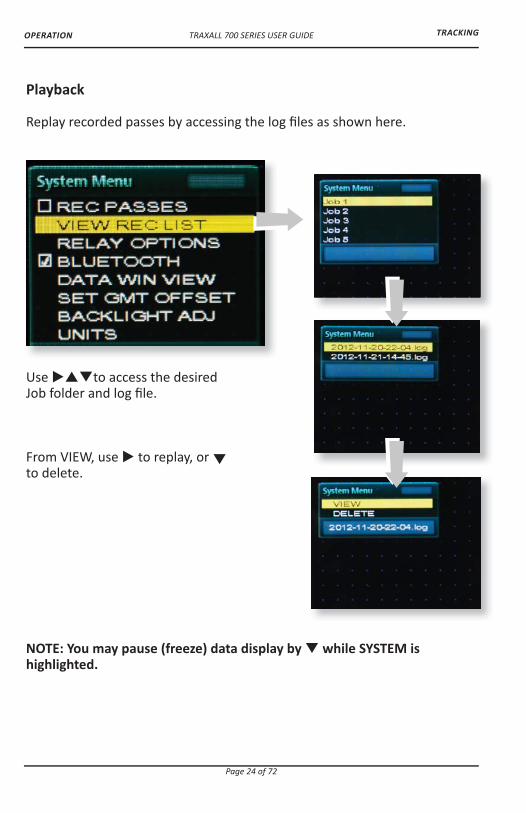
Playback
Replay recorded passes by accessing the log � les as shown here.
Use ���to access the desired Job folder and log � le.
From VIEW, use � to replay, or � to delete.
NOTE: You may pause (freeze) data display by � while SYSTEM is highlighted.
TRACKING
TRAXALL 700 SERIES USER GUIDE
Page 25 of 72
OPERATION
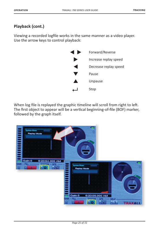
Playback (cont.)
Viewing a recorded log� le works in the same manner as a video player. Use the arrow keys to control playback:
When log � le is replayed the graphic � meline will scroll from right to le� . The � rst object to appear will be a ver� cal beginning-of-� le (BOF) marker, followed by the graph itself.
��� Forward/Reverse
� Increase replay speed
� Decrease replay speed
� Pause
� Unpause
� Stop
TRACKING

TRAXALL 700 SERIES USER GUIDE
Page 26 of 72
OPERATION
Playback (cont.)
Recorded passage is indicated by graph peak. Note Pinpointer is also con� rming passage (see pg. 31).
Reappearance of the BOF marker indicates conclusion of log � le which will con� nually loop un� l stopped.
Recorded passage can be viewed in TRANS HISTORY (default) or AXIS HISTORY modes. However, TRANS FFT display is available in real � me only. (See pg. 40–42 for more informa� on on these display modes.)
To change view mode from TRANS HISTORY to TRANS AXIS, go to the DATA WIN VIEW system menu before entering the VIEW REC LIST menu.
Here Job 1 is shown in TRANS AXIS view.
TRACKING

TRAXALL 700 SERIES USER GUIDE
Page 27 of 72
OPERATION
Tracking Example 2
SETTINGS:
Pig: Magne� c Flux Leakage (MFL) Fill se� ng: Mag Record mode: Manual
NOTE: Unless the MFL tool is con� gured with an ILI transmi� er,* Fill mode must be set to Mag or Legacy when manually tracking/recording magne� c � ux leakage devices. Standalone MFL detec� on is somewhat di� erent from transmi� er detec� on; as there is no ac� ve transmi� er, e� ec� veness will depend upon variable factors including proximity, pipe material and wall thickness, etc. Preliminary � eld tes� ng indicates e� ec� ve MFL-to-Traxall proximity is within 4.5 meters.
Logging Data
Unlike AUTO TRIGGER mode, TRAXALL begins recording as soon as you enter manual mode.
Here, transmi� er proximity is indicated. Polarity shi� indicates point of passage (Red triangle indicates automa� c MR reset.)
* Inline inspec� on (ILI) transmi� ers are tracked in Legacy mode (see following example on pg. 29)
TRACKING
Automa� c MR reset

TRAXALL 700 SERIES USER GUIDE
Page 28 of 72
OPERATION
TRAXALL will con� nually write passage data to the log� le un� l REC PASSES is unchecked.
Playback
Replay recorded passes in the same manner as Job 1 (pgs. 22–26).
TRANS HISTORY
AXIS HISTORY
TRACKING

TRAXALL 700 SERIES USER GUIDE
Page 29 of 72
OPERATION
Tracking Example 3
SETTINGS:
Transmi� er: CD42-T0 Fill se� ng: Legacy Record mode: Auto
NOTE: Fill mode must be set to Mag or Legacy when manually tracking/recording 22Hz single-frequency transmi� ers.
Wai� ng for Trigger
As you are in AUTO TRIGGER, TRAXALL will remain in a wait-state un� l a pig transmi� er reaches the sensor
Verifying Passage
The pig has passed through this loca� on, and TRAXALL is now verifying and logging passage
y g
TRACKING

TRAXALL 700 SERIES USER GUIDE
Page 30 of 72
OPERATION
Passage Logged
TRAXALL is wri� ng passage informa� on to the Job 1 folder of system memory. (You may review this passage at any � me via VIEW REC LIST menu.) TRAXALL is ready for the next passage.
Playback
Replay recorded passes in the same manner as Job 1 (pgs. 22–26).
TRANS HISTORY
AXIS HISTORY
TRACKING

TRAXALL 700 SERIES USER GUIDE
Page 31 of 72
OPERATION
Pinpoin� ng
Using your TRAXALL to � nd a sta� onary pig. The Pinpointer will help you � nd CDI X-Series or “Legacy” transmi� ers.*
Known: pipeline last recorded posi� on (“A”) � ow direc� on (“A” to “B”) transmi� er type (CDI X100) Unknown: present loca� on of obstructed pig
*MFL pigs are not located with the Pinpointer; rather, you use the tracking capability to locate the magne� c passage detec� on (see Tracking Example 2, pg. 27)
)
ed pig i
ess ess
PINPOINTING
TRAXALL 700 SERIES USER GUIDE
Page 32 of 72
OPERATION
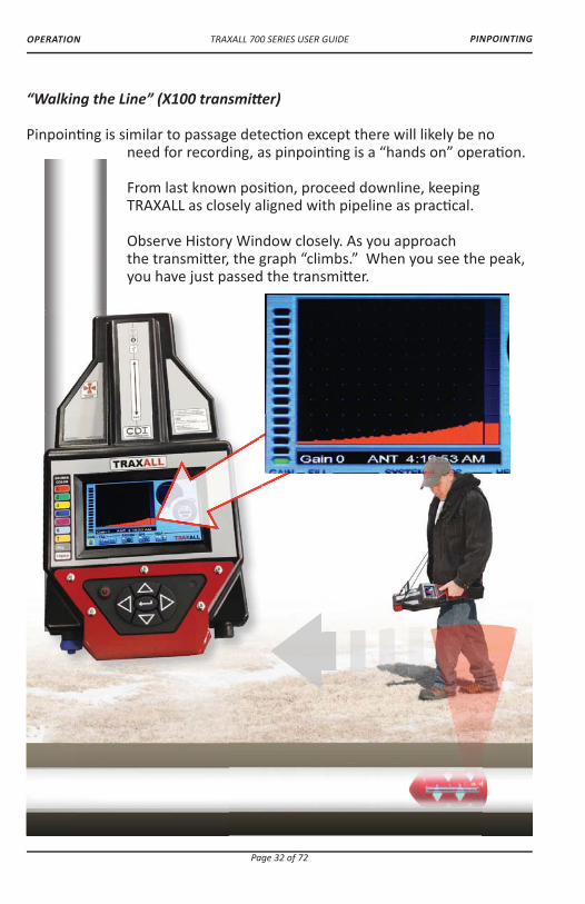
“Walking the Line” (X100 transmi� er)
Pinpoin� ng is similar to passage detec� on except there will likely be no need for recording, as pinpoin� ng is a “hands on” opera� on.
From last known posi� on, proceed downline, keeping TRAXALL as closely aligned with pipeline as prac� cal.
Observe History Window closely. As you approach the transmi� er, the graph “climbs.” When you see the peak, you have just passed the transmi� er.
PINPOINTING

TRAXALL 700 SERIES USER GUIDE
Page 33 of 72
OPERATION
“Walking the Line” (cont.)
When you have passed the transmi� er, turn and retrace your steps back toward the transmi� er while watching the Pinpointer dial. The four “pie wedge” shaped markers in the dial func� on as precision sigh� ng cross hairs.
As you return to the transmi� er, the upper and lower markers will increase in size as signal strength along the axis of magne� c � ux lines increases.
PINPOINTING
TRAXALL 700 SERIES USER GUIDE
Page 34 of 72
OPERATION
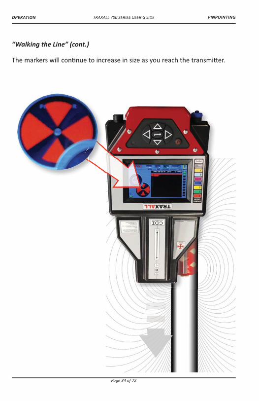
“Walking the Line” (cont.)
The markers will con� nue to increase in size as you reach the transmi� er.
PINPOINTING

TRAXALL 700 SERIES USER GUIDE
Page 35 of 72
OPERATION
Here, your TRAXALL’s pinpoint sensor is directly over the X100 magne� c null zone. The pinpointer markers are full size and outlined. You have located the X100 transmi� er!
PINPOINTING
TRAXALL 700 SERIES USER GUIDE
Page 36 of 72
OPERATION
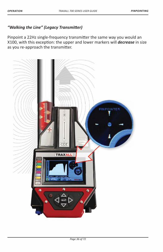
“Walking the Line” (Legacy Transmi� er)
Pinpoint a 22Hz single-frequency transmi� er the same way you would an X100, with this excep� on: the upper and lower markers will decrease in size as you re-approach the transmi� er.
PINPOINTING
TRAXALL 700 SERIES USER GUIDE
Page 37 of 72
OPERATION
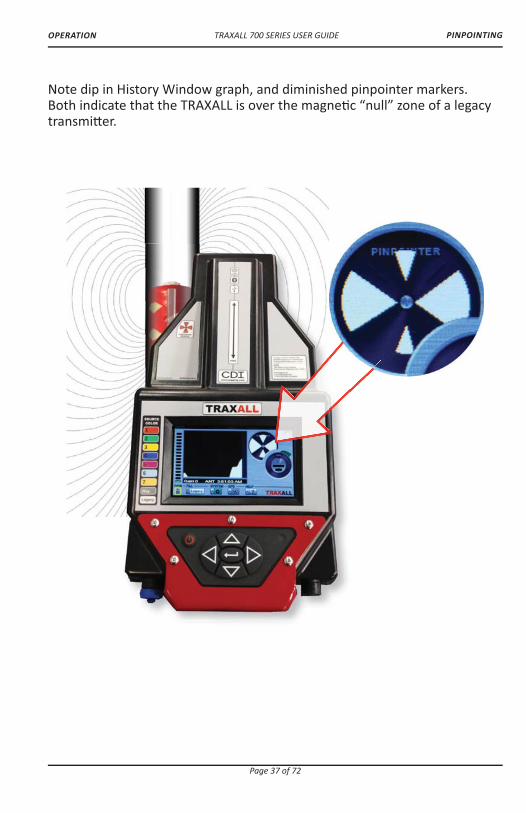
Note dip in History Window graph, and diminished pinpointer markers. Both indicate that the TRAXALL is over the magne� c “null” zone of a legacy transmi� er.
PINPOINTING

TRAXALL 700 SERIES USER GUIDE
Page 38 of 72
APPENDIX
APPENDIX
System Menu Tree
Relay Op� ons
Set up and program the two RELAYS for various pulse train behavior. The relay contacts can be used for passage annuncia� on (lights, horns, etc.), a very useful feature where an unmanned passage must be monitored.
RELAY ONE and/or RELAY TWO can be set for NORMALLY OPEN, NORMALLY CLOSED, TIME ON or OFF, and CYCLES.
Relay dwell � mes are in seconds. Values are displayed in red un� l con� rmed by ��, at which point values are shown in black.
SYSTEM MENU

TRAXALL 700 SERIES USER GUIDE
Page 39 of 72
APPENDIX
Relay Op� ons (cont.)
Set CYCLES for desired number of relay repe� � ons.
RESET deac� vates a triggered relay. (It does not change relay se� ngs.)
SYSTEM MENU

TRAXALL 700 SERIES USER GUIDE
Page 40 of 72
APPENDIX
Data Win View
DATA WIN VIEW o� ers three ways of graphing transmi� er passage.
TRANS HISTORY is the default data display mode. It is an X–Y graph, where X=Time and Y=Signal Magnitude. When TRAXALL is set to TRANS HISTORY, passage data can be viewed in real � me, or, if recorded, the log � le can be replayed at a later � me.
SYSTEM MENU

TRAXALL 700 SERIES USER GUIDE
Page 41 of 72
APPENDIX
X = Signal Frequency Y = Signal Magnitude
Here, the un� ltered signal is represented by the white graph line; the red line represents the same signal a� er enhancement by the TRAXALL DSP (digital signal processor).
Data Win View (con� nued)
TRANS FFT (Fast Fourier transform) is a � me-to-frequency conversion algorithm where X=Signal Frequency and Y = Signal Magnitude. When TRAXALL is set to TRANS FFT, passage data can be viewed in real � me only.
SYSTEM MENU
TRAXALL 700 SERIES USER GUIDE
Page 42 of 72
APPENDIX
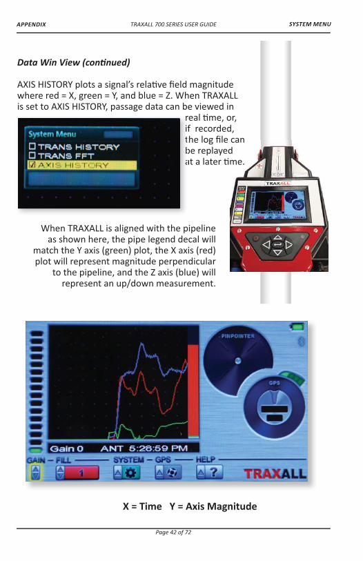
X = Time Y = Axis Magnitude
Data Win View (con� nued)
AXIS HISTORY plots a signal’s rela� ve � eld magnitude where red = X, green = Y, and blue = Z. When TRAXALL is set to AXIS HISTORY, passage data can be viewed in
real � me, or, if recorded, the log � le can be replayed at a later � me.
When TRAXALL is aligned with the pipeline as shown here, the pipe legend decal will
match the Y axis (green) plot, the X axis (red) plot will represent magnitude perpendicular
to the pipeline, and the Z axis (blue) will represent an up/down measurement.
ritba
can dme.
SYSTEM MENU

TRAXALL 700 SERIES USER GUIDE
Page 43 of 72
APPENDIX
Set GMT O� set
This command resets the magnet-resis� ve sensor (used in Pinpoint and Mag modes) by realigning the magnet dipoles.
With SET GMT OFFSET highlighted, � to highlight GMT OFFSET, then � again (GMT OFFSET text will turn red).
Default is 0. Use �� to advance or set back according to your local � me zone. Press Enter to con� rm and set.
If Daylight Savings Time (DST) is being observed in your area, use � to check the DST box. Pressing � again will uncheck the box.
SYSTEM MENU

TRAXALL 700 SERIES USER GUIDE
Page 44 of 72
APPENDIX
Backlight Adjustment
TRAXALL LCD brightness is automa� cally adjusted for op� mal visibility and ba� ery life by the built-in Automa� c Light Sensor (ALS). The LCD will also “go blank” (turn o� ) a� er one minute of non-use. But you can override the ALS by controlling both brightness and blanking intervals through this menu.
Use the ��to access MAN LEVEL to adjust LCD brightness to your preferred (1–5) level.*
Values selected for change are displayed in red un� l con� rmed by pressing ��, at which point values are shown in black.
Blanking delay can be set in ten-second increments from 10–60 seconds, or None.
* ALS levels are 1 through 4. Level 5 is accessible only in manual mode and should be used only when necessary (i.e., when working under bright sunlight) as it can draw extra ba� ery current.
SYSTEM MENU
TRAXALL 700 SERIES USER GUIDE
Page 45 of 72
APPENDIX
Global Posi� oning System (GPS)
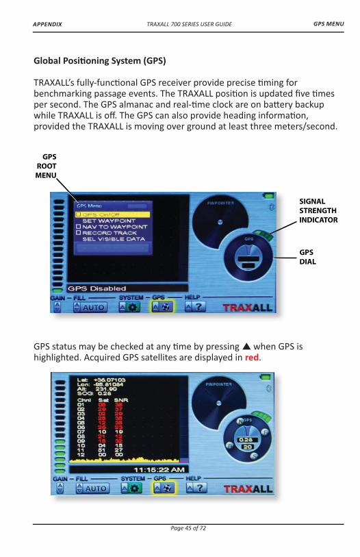
TRAXALL’s fully-func� onal GPS receiver provide precise � ming for benchmarking passage events. The TRAXALL posi� on is updated � ve � mes per second. The GPS almanac and real-� me clock are on ba� ery backup while TRAXALL is o� . The GPS can also provide heading informa� on, provided the TRAXALL is moving over ground at least three meters/second.
GPS status may be checked at any � me by pressing ��when GPS is highlighted. Acquired GPS satellites are displayed in red.
GPSROOT
MENU
GPSDIAL
SIGNALSTRENGTHINDICATOR
GPS MENU

TRAXALL 700 SERIES USER GUIDE
Page 46 of 72
APPENDIX
GPS Setup and Opera� on
From the GPS menu, use ��to access GPS On/O� checkbox, then � or ��to check. This will enable the GPS.
Once enabled, it will begin searching for GPS satellites. When three satellites are acquired, the signal strength indicator bars will change from dark green to light green and the GPS dialwill become ac� ve.
The GPS is now ready for
• Se� ng waypoints• Naviga� ng to waypoints• Recording a traverse
GPS MENU
CLOSINGDISTANCE
“GOLF TEE” POINTER
HEADING

TRAXALL 700 SERIES USER GUIDE
Page 47 of 72
APPENDIX
GPS Setup and Opera� on
When you have selected a func� on, you will be prompted to assign your task to one of � ve Job folders.
The Job folders are where waypoint (*.wpt) and tracking (*.nmea) � les are stored.
GPS MENU

TRAXALL 700 SERIES USER GUIDE
Page 48 of 72
APPENDIX
GPS Setup and Opera� on (cont.)
SELect VISIBLE DATA to choose either CLOSING DISTance, ALTITUDE, or GROUND SPEED values in the range por� on of the GPS dial.
GPS MENU
TRAXALL 700 SERIES USER GUIDE
Page 49 of 72
APPENDIX
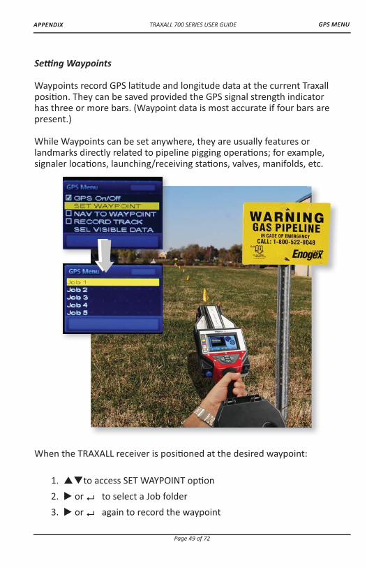
Se� ng Waypoints
Waypoints record GPS la� tude and longitude data at the current Traxall posi� on. They can be saved provided the GPS signal strength indicator has three or more bars. (Waypoint data is most accurate if four bars are present.)
While Waypoints can be set anywhere, they are usually features or landmarks directly related to pipeline pigging opera� ons; for example, signaler loca� ons, launching/receiving sta� ons, valves, manifolds, etc.
When the TRAXALL receiver is posi� oned at the desired waypoint:
1. ��to access SET WAYPOINT op� on2. � or ��to select a Job folder 3. � or ��again to record the waypoint
GPS MENU

TRAXALL 700 SERIES USER GUIDE
Page 50 of 72
APPENDIX
Waypoints are stored in the Job folders as *.wpt � les.
Each waypoint � le contains• Date • Time• La� tude • Longitude• Eleva� on
Once set, recorded waypoints may be displayed, navigated to, or deleted.
GPS MENU

TRAXALL 700 SERIES USER GUIDE
Page 51 of 72
APPENDIX
Recording Tracks
In addi� on to storing waypoints, you may record an en� re traverse for later viewing and analysis in Google Earth. Track recording may be done along with other TRAXALL opera� ons such as passage detec� on and/or pinpoin� ng.
1. ��to access RECORD TRACK op� on2. � or ��to begin logging3. � or ��to stop logging
Page 51 of 72
GPS TRACKING

TRAXALL 700 SERIES USER GUIDE
Page 52 of 72
APPENDIX
Downloading to Google Earth
A� er recording your track(s), connect TRAXALL to a laptop or PC.
When connected, TRAXALL will register as a mass storage device.
Open Google Earth on your laptop/PC, and “drag and drop” an NMEA � le from the � le list over to the Google Earth applica� on.
Google Earth will import and superimpose track path, points, and other informa� on onto its satellite imagery.
GPS & MAPPING
TRAXALL 700 SERIES USER GUIDE
Page 53 of 72
APPENDIX
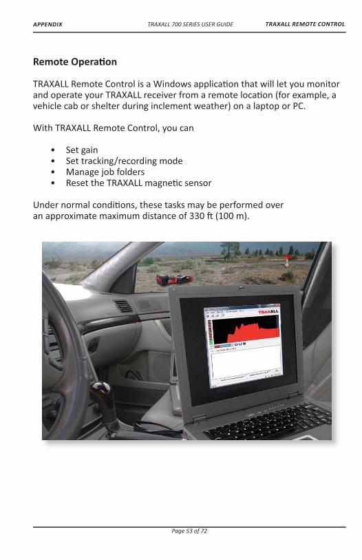
Remote Opera� on
TRAXALL Remote Control is a Windows applica� on that will let you monitor and operate your TRAXALL receiver from a remote loca� on (for example, a vehicle cab or shelter during inclement weather) on a laptop or PC.
With TRAXALL Remote Control, you can
• Set gain • Set tracking/recording mode • Manage job folders • Reset the TRAXALL magne� c sensor
Under normal condi� ons, these tasks may be performed over an approximate maximum distance of 330 � (100 m).
TRAXALL REMOTE CONTROL

TRAXALL 700 SERIES USER GUIDE
Page 54 of 72
APPENDIX
1. Start BluetoothFrom your TRAXALL receiver SYSTEM menu, highlight BLUETOOTH* op� on and ��to enable Bluetooth communica� on. The Bluetooth icon will change from grey to blue to con� rm.
A “BTooth Discoverable” prompt means that TRAXALL Bluetooth is ac� ve, but it is s� ll necessary to establish communica� on with your PC or laptop and then launch the TRAXALL Remote Control applica� on. (See following pages.)
*NOTE: only Microso� Bluetooth drivers are supported by TRAXALL. Contact CDI �������� �� �����or 1-800-580-4234 if you require Bluetooth connec� vity assistance.
TRAXALL REMOTE CONTROL
TRAXALL 700 SERIES USER GUIDE
Page 55 of 72
APPENDIX
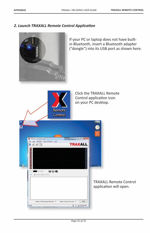
2. Launch TRAXALL Remote Control Applica� on
If your PC or laptop does not have built-in Bluetooth, insert a Bluetooth adapter (“dongle”) into its USB port as shown here.
TRAXALL REMOTE CONTROL
Click the TRAXALL Remote Control applica� on icon on your PC desktop.
TRAXALL Remote Control applica� on will open.

TRAXALL 700 SERIES USER GUIDE
Page 56 of 72
APPENDIX
3. Select Bluetooth Device
Click on the Bluetooth toolbar bu� on to open the Device Survey Window
The Device Survey Window will display TRAXALL devices as they are found.
TRAXALL REMOTE CONTROL
Green check mark indicates TRAXALL unit or units are now con� gured for use on your PC.
“Clock” indicates TRAXALL unit or units are being con� gured for use on your PC.
TRAXALL 700 SERIES USER GUIDE
Page 57 of 72
APPENDIX
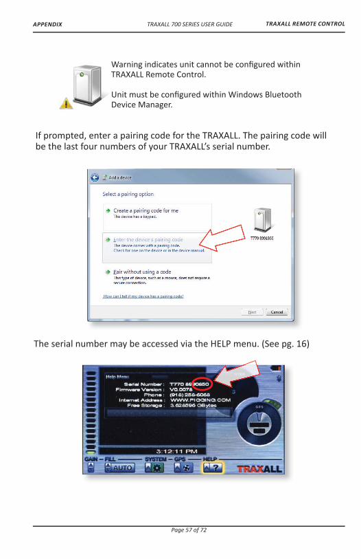
If prompted, enter a pairing code for the TRAXALL. The pairing code will be the last four numbers of your TRAXALL’s serial number.
TRAXALL REMOTE CONTROL
The serial number may be accessed via the HELP menu. (See pg. 16)
Warning indicates unit cannot be con� gured within TRAXALL Remote Control.
Unit must be con� gured within Windows Bluetooth Device Manager.

TRAXALL 700 SERIES USER GUIDE
Page 58 of 72
APPENDIX
Select desired device and then click OK bu� on to begin connec� on.
When communica� on is established, the Bluetooth icon will change from blue to green.
TRAXALL REMOTE CONTROL

TRAXALL 700 SERIES USER GUIDE
Page 59 of 72
APPENDIX
4. Link Bluetooth Device
If the TRAXALL Remote Control applica� on window on your PC shows TRAXALL ac� vity you have communica� on.
TRAXALL REMOTE CONTROL
TRAXALL 700 SERIES USER GUIDE
Page 60 of 72
APPENDIX
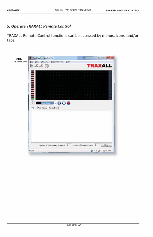
5. Operate TRAXALL Remote Control
TRAXALL Remote Control func� ons can be accessed by menus, icons, and/or tabs.
MENUOPTIONS [
TRAXALL REMOTE CONTROL

TRAXALL 700 SERIES USER GUIDE
Page 61 of 72
APPENDIX
MENU OPTIONS
File Save Saves text in Log Window to a � le Exit Closes the TRAXALL Remote Control applica� on
View Devices Opens Device Survey Window Tool Bar Check/uncheck to show Status Bar Check/uncheck to show
TRAXALL Transport Live Pause Stop These commands control History Window data stream from TRAXALL receiver. They do not control TRAXALL func� ons, but control only the real-� me display seen at the PC end. Gain Controls TRAXALL receiver sensi� vity. Increase + Decrease -
Record Op� ons These commands func� on exactly as on the TRAXALL receiver unit.
Working Folder Assign passage recordings to any of � ve job folders for later review Automa� c TRAXALL will remain in a wait-state un� l a pig transmi� er reaches the sensor Manual Prepares TRAXALL for user-controlled Start/Stop recording (see Record Control bu� ons)
Help So� ware Version and Build informa� on
TRAXALL REMOTE CONTROL

TRAXALL 700 SERIES USER GUIDE
Page 62 of 72
APPENDIX
MANUAL RECORDCONTROL
PASSAGEPROMPT
GAINCONTROL
GAIN STRENGTHINDICATOR
TRANSMITTERSELECTOR
HISTORY WINDOW
TOOL BAR
DATASTREAMCONTROLS
[
Operate TRAXALL Remote Control (cont.).
TRAXALL REMOTE CONTROL

TRAXALL 700 SERIES USER GUIDE
Page 63 of 72
APPENDIX
TOOL BAR Bluetooth Wizard Connect Disconnect
HISTORY WINDOWReal-� me graphic plot of transmi� er passage
PASSAGE PROMPTWhen TRAXALL receiver is recording, these prompts will show in successive order
Wai� ng for Trigger. Verifying Passage Logging Data MANUAL RECORD CONTROLStart/Stop recording when in Manual mode
DATA STREAM CONTROLSSame func� on as TRAXALL-Transport op� ons (pg. 64) These commands control the display stream from the TRAXALL History Window.
Live Pause Stop
TRANSMITTER SELECTORSimilar to the TRAXALL receiver FILL menu. Use the drop-down menu to select transmi� er type.
Auto Select Transmi� er 1–7 Mag Legacy
Selec� on of one type excludes others.
GAIN CONTROL & INDICATOR
���to increase/decrease TRAXALL receiver sensi� vity.Green/red LED stack indicates current sensi� vity level
TRAXALL REMOTE CONTROL

TRAXALL 700 SERIES USER GUIDE
Page 64 of 72
APPENDIX
Operate TRAXALL Remote Control (cont.).
INFO DISPLAY
TABS
CLEAR BUTTON
PASSAGE & EVENT COUNTERS
INFO DISPLAY
WINDOW
TRAXALL REMOTE CONTROL

TRAXALL 700 SERIES USER GUIDE
Page 65 of 72
APPENDIX
INFO DISPLAY WINDOW & TABS
Choose between:
Log Tracking informa� on in text format
Axis History Real-� me plots of signal rela� ve � eld magnitude where red = X, green = Y, and blue = Z
Device InfoTRAXALL unit and GPS informa� on
Passage and Event CountersNumber of pig passages/Ignored events
ClearClears Log Window and Passage and Event counter entries
TRAXALL REMOTE CONTROL

TRAXALL 700 SERIES USER GUIDE
Page 66 of 72
APPENDIX
Operate TRAXALL Remote Control (cont.).
BATTERY STATUSCONNECTION STATUS
SIGNAL STRENGTHTIME
APPLICATIONSTATUS
STATUS BAR [
TRAXALL REMOTE CONTROL

TRAXALL 700 SERIES USER GUIDE
Page 67 of 72
APPENDIX
STATUS BAR
Applica� on Status Displays current state of TRAXALL Remote Control applica� on Connec� on Status Color = connected; Grey = disconnected
Ba� ery TRAXALL ba� ery charge status
Signal Strength TRAXALL-PC Bluetooth link
Time Local � me-of-day
TRAXALL REMOTE CONTROL
TRAXALL 700 SERIES USER GUIDE
Page 68 of 72
OPTIONS
OPTIONAL EQUIPMENT
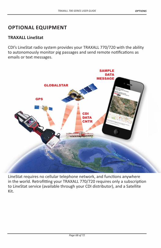
TRAXALL LineStat
CDI’s LineStat radio system provides your TRAXALL 770/720 with the ability to autonomously monitor pig passages and send remote no� � ca� ons as emails or text messages.
GPS
GLOBALSTAR
CDI DATA CNTR
SAMPLE DATA
MESSAGE
LineStat requires no cellular telephone network, and func� ons anywhere in the world. Retro� � ng your TRAXALL 770/720 requires only a subscrip� on to LineStat service (available through your CDI distributor), and a Satellite Kit.

TRAXALL 700 SERIES USER GUIDE
Page 69 of 72
OPTIONS
Page 69 of 72
TRAXALLCONVERSION
KIT
TRAXALL WITH LINESTAT

TRAXALL 700 SERIES USER GUIDE
Page 70 of 72
APPENDIX
Warranty
All equipment sold by Control Devices, Incorporated (CDI) is warranted for a period of one (1) year from the date of shipment to Purchaser, providing the instrument or equipment has not been modi� ed, abused, or used for purposes which it was not designed for.
Ba� eries, probes, leads, magnets, and other consumables subject to wear are not covered by this warranty. CDI will repair or replace faulty equipment during the warranty period when the cause is a defect arising from faulty design, materials or workmanship.
Making a Warranty Claim
Equipment being considered for warranty repair, or a representa� ve sample thereof, must be returned to CDI at the Purchaser’s expense. The equipment must be accompanied by the Purchaser’s wri� en order* describing the defect(s) and authorizing CDI to invoice the Purchaser for any charges not covered by the warranty.
Upon receipt of the equipment and Purchase Order, CDI will examine the equipment and make a determina� on of the nature and cause of the defect. If the defect is not covered by the warranty, CDI will quote to Purchaser the cost for replacement or repair equipment, and will not proceed un� l Purchaser delivers a wri� en acceptance of the quota� on.
During the one year warranty, CDI will bear the cost to return units repaired under the warranty back to the Purchaser’s domes� c premises. CDI will return units to foreign countries at Purchaser’s expense.
* Contact CDI at 1-800-580-4234, ext 143 for CDI RMA Form FM-03-0089
WARRANTY
TRAXALL 700 SERIES USER GUIDE
Page 71 of 72
APPENDIX CARE, MAINTENANCE, & SERVICING
Care and Maintenance
Equipment designed by CDI is protected against the environment in which it is intended to operate. Much of the equipment is designed for prolonged use in the � eld without any special maintenance other than rou� ne ba� ery replacements. It is the Purchaser’s responsibility to insure that proper precau� ons are taken during installa� on and opera� on so that weather seals are in place, rou� ne maintenance occurs, etc. Failure to perform these opera� ons nulli� es this warranty.
CDI equipment should only be operated by quali� ed personnel who are familiar with any and all manuals and procedures for said equipment’s opera� on.
Service and Repairs
Cost for repairs not covered by the warranty or carried out a� er the warranty period has expired will be charged at the current hourly or set service rate, plus the cost of materials, upon approval by Purchaser.
Equipment for repair must be sent at the Purchaser’s expense and be accompanied by the Purchaser’s wri� en order describing the defect and authorizing CDI to invoice the Purchaser for labor, materials and return delivery cost.
No service or repair will be undertaken un� l an approved wri� en order is received from the Purchaser.
Opera� ng equipment while in a damaged condi� on nulli� es this warranty.