vasimr plasma rocket technology - wordpress.com petro advanced space propulsion laboratory nasa jsc...
TRANSCRIPT

Andrew Petro Advanced Space Propulsion Laboratory
NASA JSC Houston, TexasMay 2002
VASIMR Plasma Rocket Technology

NASA Johnson Space Center, Advanced Space Propulsion Laboratory
OUTLINE
• Introduction
• Development Roadmap
• Flight Demonstration Concepts
• Mission Applications
• Experimentation
• Source, ICRF, Nozzle
• Theoretical Studies
• Source, ICRF, Nozzle
Andrew Petro
Andrew Ilin
VASIMR Plasma Rocket Technology
NASA Johnson Space Center, Advanced Space Propulsion Laboratory
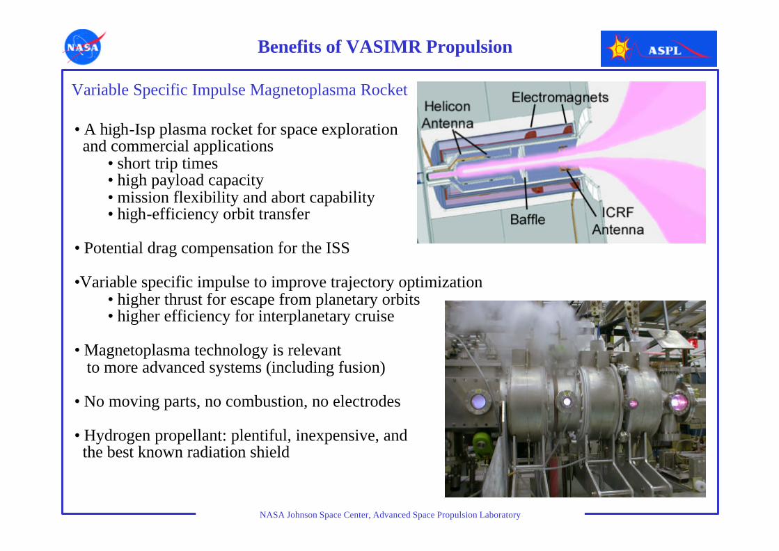
• A high-Isp plasma rocket for space exploration and commercial applications
• short trip times• high payload capacity• mission flexibility and abort capability• high-efficiency orbit transfer
• Potential drag compensation for the ISS
•Variable specific impulse to improve trajectory optimization• higher thrust for escape from planetary orbits• higher efficiency for interplanetary cruise
• Magnetoplasma technology is relevant to more advanced systems (including fusion)
• No moving parts, no combustion, no electrodes
• Hydrogen propellant: plentiful, inexpensive, and the best known radiation shield
Variable Specific Impulse Magnetoplasma Rocket
Benefits of VASIMR Propulsion
NASA Johnson Space Center, Advanced Space Propulsion Laboratory
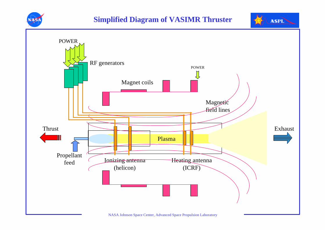
Propellant feed Ionizing antenna
(helicon)
Magnetic field lines
Exhaust
Heating antenna (ICRF)
Plasma
Magnet coils
RF generators
POWER
POWER
Thrust
Simplified Diagram of VASIMR Thruster
NASA Johnson Space Center, Advanced Space Propulsion Laboratory
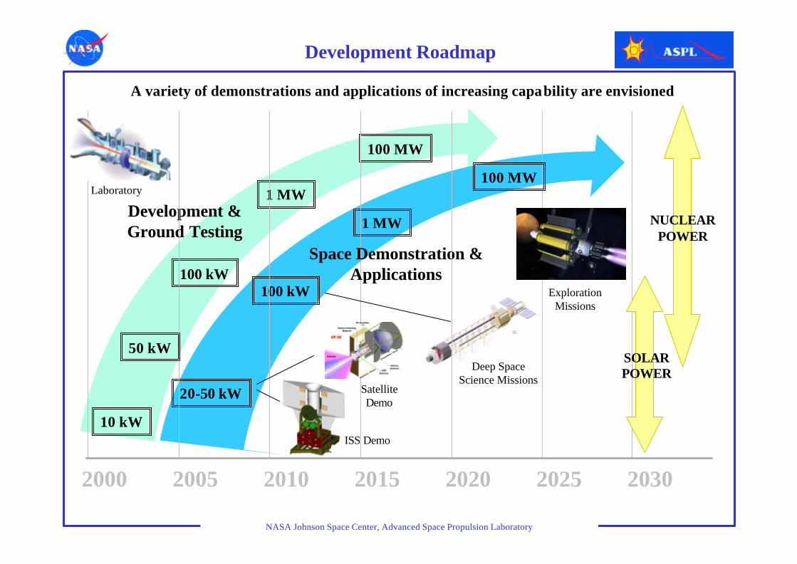
Development & Ground Testing
2000 2005 2010 2015 2020 2025 2030
20-50 kW
100 kW
1 MW
10 kW
50 kW
100 kW
1 MW
100 MW
SOLARPOWER
NUCLEARPOWER
Space Demonstration & Applications
100 MW
Development Roadmap
ISS Demo
Satellite Demo
Deep Space Science Missions
Exploration Missions
Laboratory
A variety of demonstrations and applications of increasing capability are envisioned
NASA Johnson Space Center, Advanced Space Propulsion Laboratory
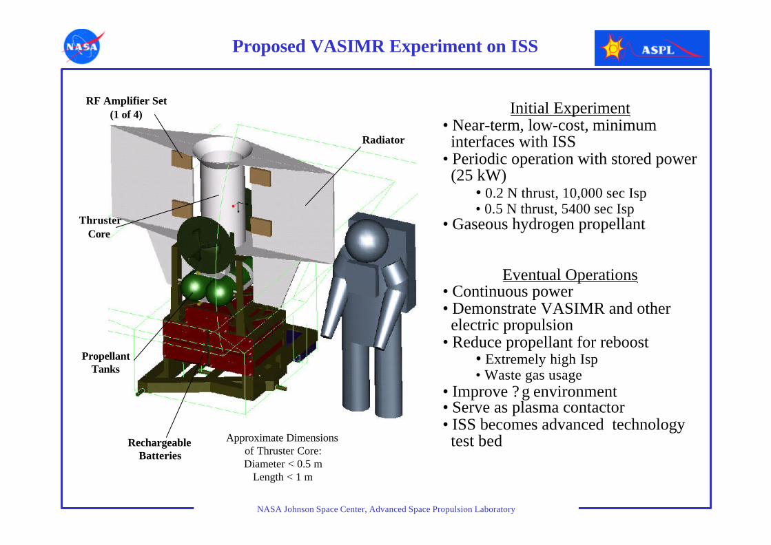
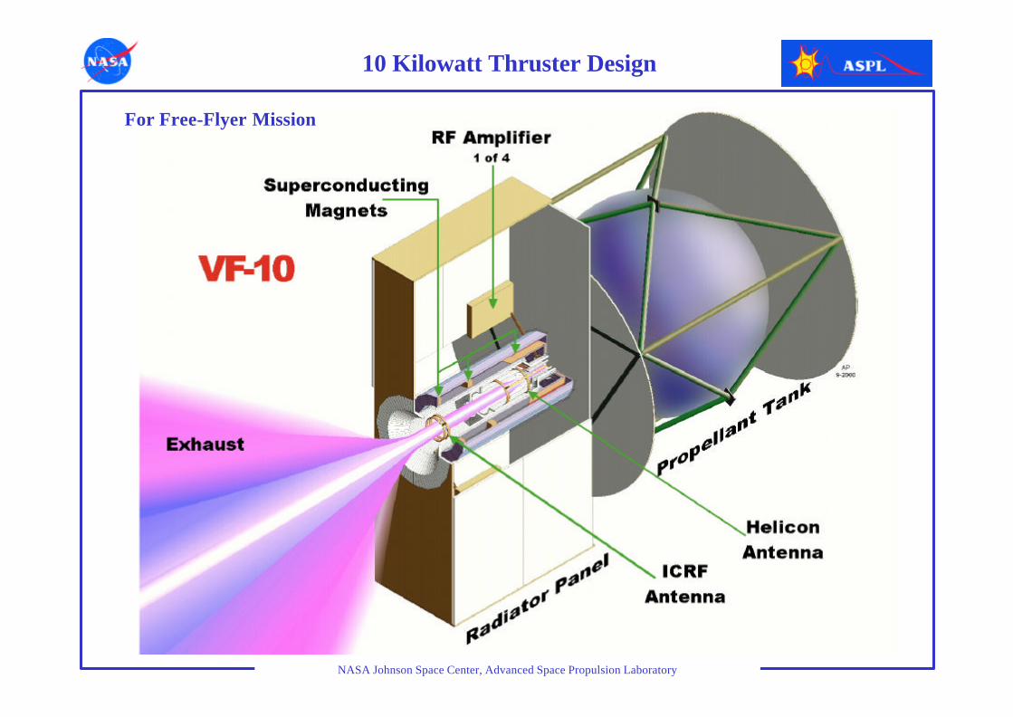
ThrusterCore
RF Amplifier Set(1 of 4)
Radiator
RechargeableBatteries
PropellantTanks
Approximate Dimensionsof Thruster Core:Diameter < 0.5 m
Length < 1 m
Proposed VASIMR Experiment on ISS
Initial Experiment• Near-term, low-cost, minimum interfaces with ISS
• Periodic operation with stored power (25 kW)
• 0.2 N thrust, 10,000 sec Isp• 0.5 N thrust, 5400 sec Isp
• Gaseous hydrogen propellant
Eventual Operations• Continuous power • Demonstrate VASIMR and other electric propulsion
• Reduce propellant for reboost• Extremely high Isp• Waste gas usage
• Improve ? g environment• Serve as plasma contactor• ISS becomes advanced technology test bed

NASA Johnson Space Center, Advanced Space Propulsion Laboratory
POTENTIAL ISS LOCATIONAttachment at external payload site on P3 (or S3) truss segment shown
Proposed VASIMR Experiment on ISS
NASA Johnson Space Center, Advanced Space Propulsion Laboratory
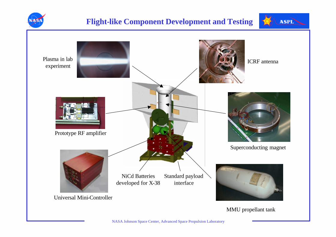
Plasma in lab experiment
Prototype RF amplifier
Universal Mini-Controller
MMU propellant tank
Superconducting magnet
ICRF antenna
Flight-like Component Development and Testing
NiCd Batteries developed for X-38
Standard payload interface

NASA Johnson Space Center, Advanced Space Propulsion Laboratory
- Demonstrate advanced space propulsion technology- Measure natural radiation environment from low to high Earth orbit
• Deploy from Shuttle and climb to high Earth orbit
• Solar Power: 10-12 kW• Demonstrate two different propulsion
systems•VASIMR•Hall thruster
• Operate scientific instruments on spacecraft and on deployed microsatellites
Free-Flying Space Demonstration
NASA Johnson Space Center, Advanced Space Propulsion Laboratory
10 Kilowatt Thruster Design
For Free-Flyer Mission
NASA Johnson Space Center, Advanced Space Propulsion Laboratory
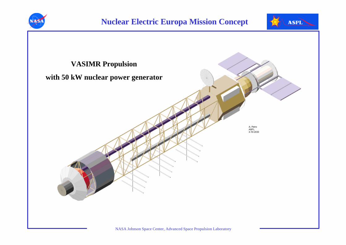
Nuclear Electric Europa Mission Concept
VASIMR Propulsion
with 50 kW nuclear power generator
NASA Johnson Space Center, Advanced Space Propulsion Laboratory
Th
rust
(N
)
n(m
-3)
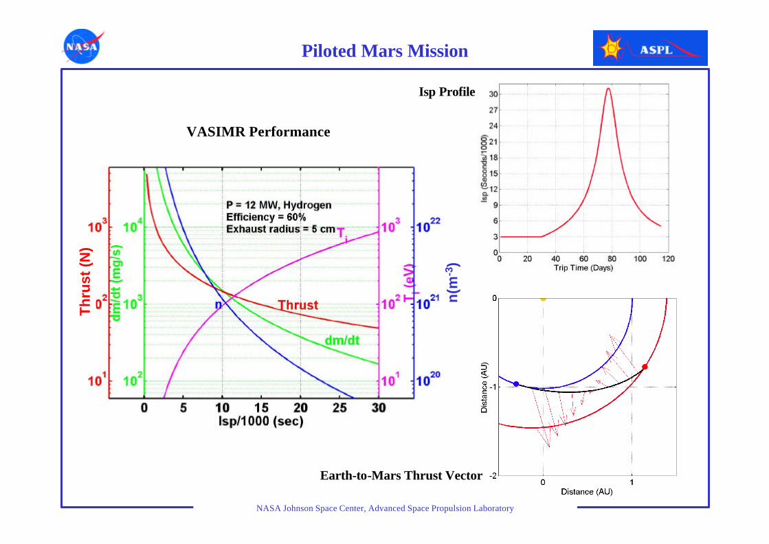
Earth-to-Mars Thrust Vector
Isp Profile
VASIMR Performance
Piloted Mars Mission
NASA Johnson Space Center, Advanced Space Propulsion Laboratory
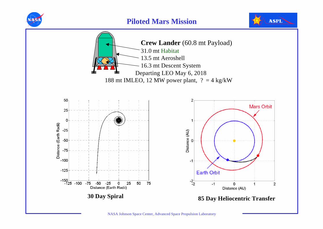
Piloted Mars Mission
Crew Lander (60.8 mt Payload)31.0 mt Habitat13.5 mt Aeroshell 16.3 mt Descent System
Departing LEO May 6, 2018188 mt IMLEO, 12 MW power plant, ? = 4 kg/kW
30 Day Spiral 85 Day Heliocentric Transfer

NASA Johnson Space Center, Advanced Space Propulsion Laboratory
Mars Mission Abort Capability
Aborts due to loss of propellant
Aborts deep into the mission due to non propulsion system failures
NASA Johnson Space Center, Advanced Space Propulsion Laboratory
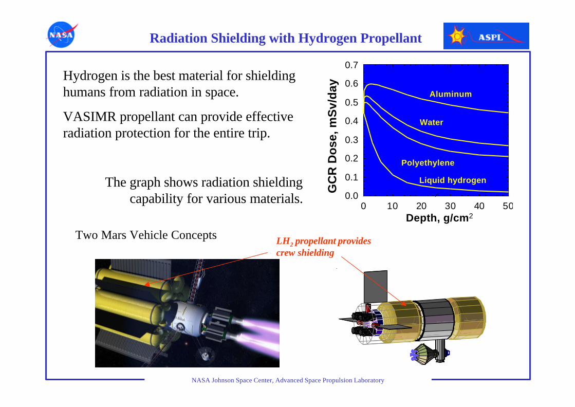
Radiation Shielding with Hydrogen Propellant
Depth, g/cm20 10 20 30 40 50
GC
R D
ose
, mS
v/d
ay
0.0
0.1
0.2
0.3
0.4
0.5
0.6
0.7
Aluminum
Water
Polyethylene
Liquid hydrogen
LH2 propellant provides crew shielding
Hydrogen is the best material for shielding humans from radiation in space.
VASIMR propellant can provide effective radiation protection for the entire trip.
The graph shows radiation shielding capability for various materials.
Two Mars Vehicle Concepts
NASA Johnson Space Center, Advanced Space Propulsion Laboratory
0
1000
2000
3000
4000
Mass (metric tons)
1Propulsion Type
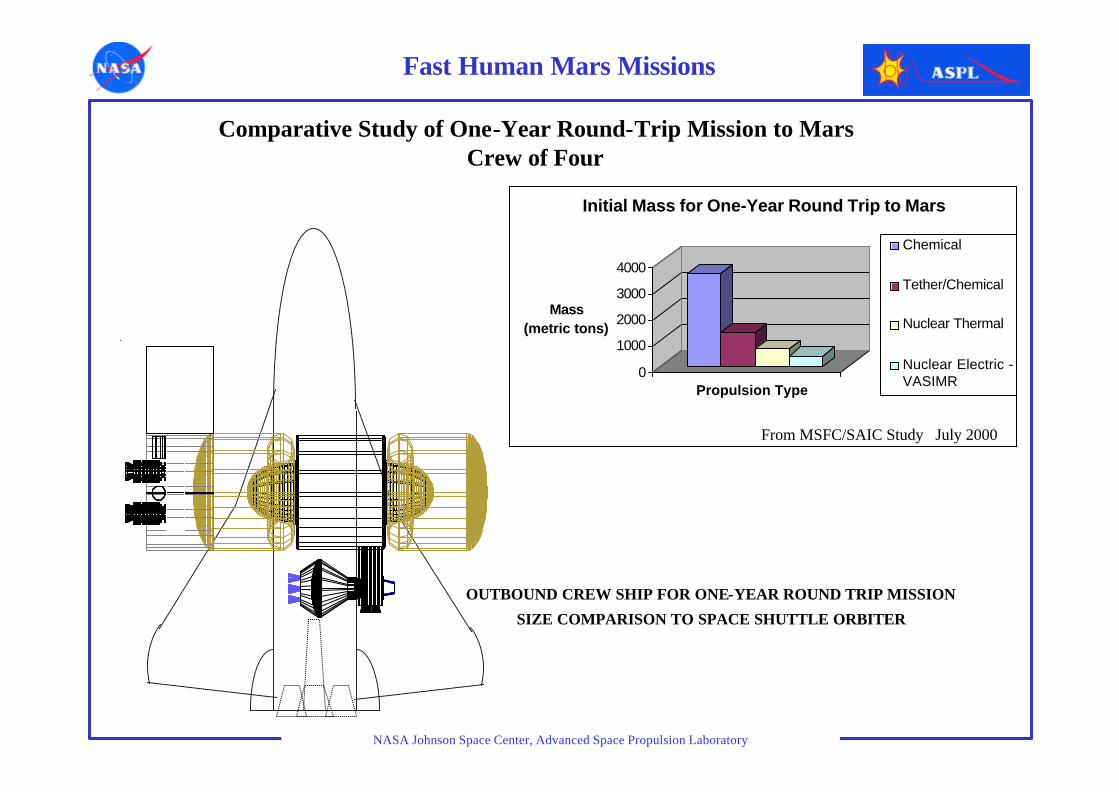
Initial Mass for One-Year Round Trip to Mars
Chemical
Tether/Chemical
Nuclear Thermal
Nuclear Electric -VASIMR
OUTBOUND CREW SHIP FOR ONE-YEAR ROUND TRIP MISSION
SIZE COMPARISON TO SPACE SHUTTLE ORBITER
Comparative Study of One-Year Round-Trip Mission to MarsCrew of Four
Fast Human Mars Missions
From MSFC/SAIC Study July 2000

NASA Johnson Space Center, Advanced Space Propulsion Laboratory
200MW Earth to Mars Missions? = 0.5
Maximal Isp = 30,000Payload Mass = 22 mt
Total Initial Spiraling around Earth Heliocentric trajectory Final relative Total tripMass (mt) fuel (mt) time (days) fuel (mt) time (days) velocity (km/s) time (days)
600 180 7 298 34 0 41350 117 5 111 42 0 47250 88 4 40 49 0 53
600 152 8 324 31 6.8 39
Higher Power Dramatically Reduces Trip Time
NASA Johnson Space Center, Advanced Space Propulsion Laboratory
Summary
• Power-rich architectures offer the most robust systems for space exploration
• High power electric propulsion with variable thrust and Isp reduces risk and provides mission flexibility
• High-Isp propulsion systems have potential in near-Earth applications
• The ISS can become an important facility for demonstrating advanced propulsion and power technology and those test operations can directly benefit the ISS.
NASA Johnson Space Center, Advanced Space Propulsion Laboratory
Backup Charts
NASA Johnson Space Center, Advanced Space Propulsion Laboratory
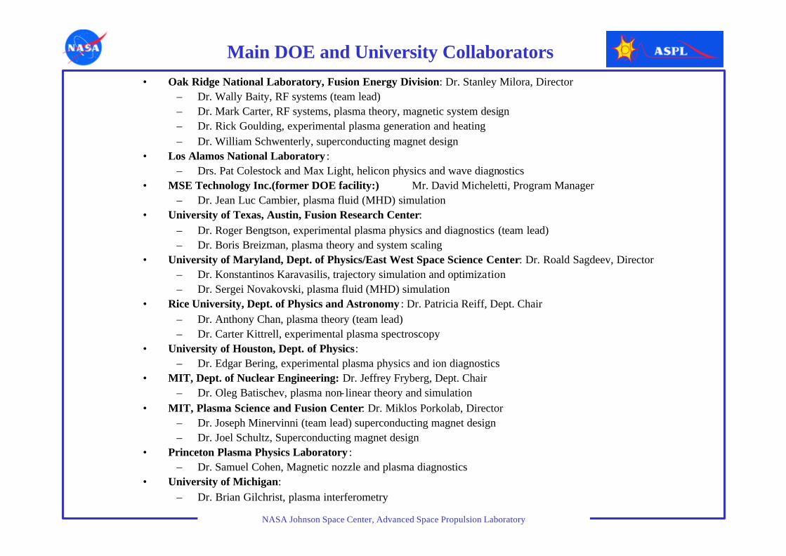
Main DOE and University Collaborators• Oak Ridge National Laboratory, Fusion Energy Division: Dr. Stanley Milora, Director
– Dr. Wally Baity, RF systems (team lead)– Dr. Mark Carter, RF systems, plasma theory, magnetic system design– Dr. Rick Goulding, experimental plasma generation and heating– Dr. William Schwenterly, superconducting magnet design
• Los Alamos National Laboratory :– Drs. Pat Colestock and Max Light, helicon physics and wave diagnostics
• MSE Technology Inc.(former DOE facility:) Mr. David Micheletti, Program Manager– Dr. Jean Luc Cambier, plasma fluid (MHD) simulation
• University of Texas, Austin, Fusion Research Center:– Dr. Roger Bengtson, experimental plasma physics and diagnostics (team lead)– Dr. Boris Breizman, plasma theory and system scaling
• University of Maryland, Dept. of Physics/East West Space Science Center: Dr. Roald Sagdeev, Director– Dr. Konstantinos Karavasilis, trajectory simulation and optimization– Dr. Sergei Novakovski, plasma fluid (MHD) simulation
• Rice University, Dept. of Physics and Astronomy : Dr. Patricia Reiff, Dept. Chair– Dr. Anthony Chan, plasma theory (team lead)– Dr. Carter Kittrell, experimental plasma spectroscopy
• University of Houston, Dept. of Physics:– Dr. Edgar Bering, experimental plasma physics and ion diagnostics
• MIT, Dept. of Nuclear Engineering: Dr. Jeffrey Fryberg, Dept. Chair– Dr. Oleg Batischev, plasma non- linear theory and simulation
• MIT, Plasma Science and Fusion Center: Dr. Miklos Porkolab, Director– Dr. Joseph Minervinni (team lead) superconducting magnet design – Dr. Joel Schultz, Superconducting magnet design
• Princeton Plasma Physics Laboratory :– Dr. Samuel Cohen, Magnetic nozzle and plasma diagnostics
• University of Michigan: – Dr. Brian Gilchrist, plasma interferometry

NASA Johnson Space Center, Advanced Space Propulsion Laboratory
0 0.2 0.4 0.6 0.8 1 1.2 1.4
-0.4
-0.3
-0.2
-0.1
0
0.1
0.2
0.3
0.4
Magnetic Field Lines
meters
meters
24 kW VASIMR50 MA/m2 currentFour coilsMagnet mass: 37 kg
Andrew Ilin
HELICON ICRF
M1 M2
M3M4
NASA Johnson Space Center, Advanced Space Propulsion Laboratory
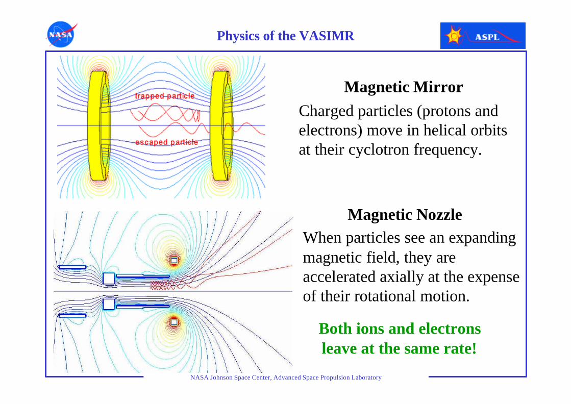
Physics of the VASIMR
Charged particles (protons and electrons) move in helical orbits at their cyclotron frequency.
When particles see an expanding magnetic field, they are accelerated axially at the expense of their rotational motion.
Magnetic Mirror
Magnetic Nozzle
Both ions and electrons leave at the same rate!
NASA Johnson Space Center, Advanced Space Propulsion Laboratory
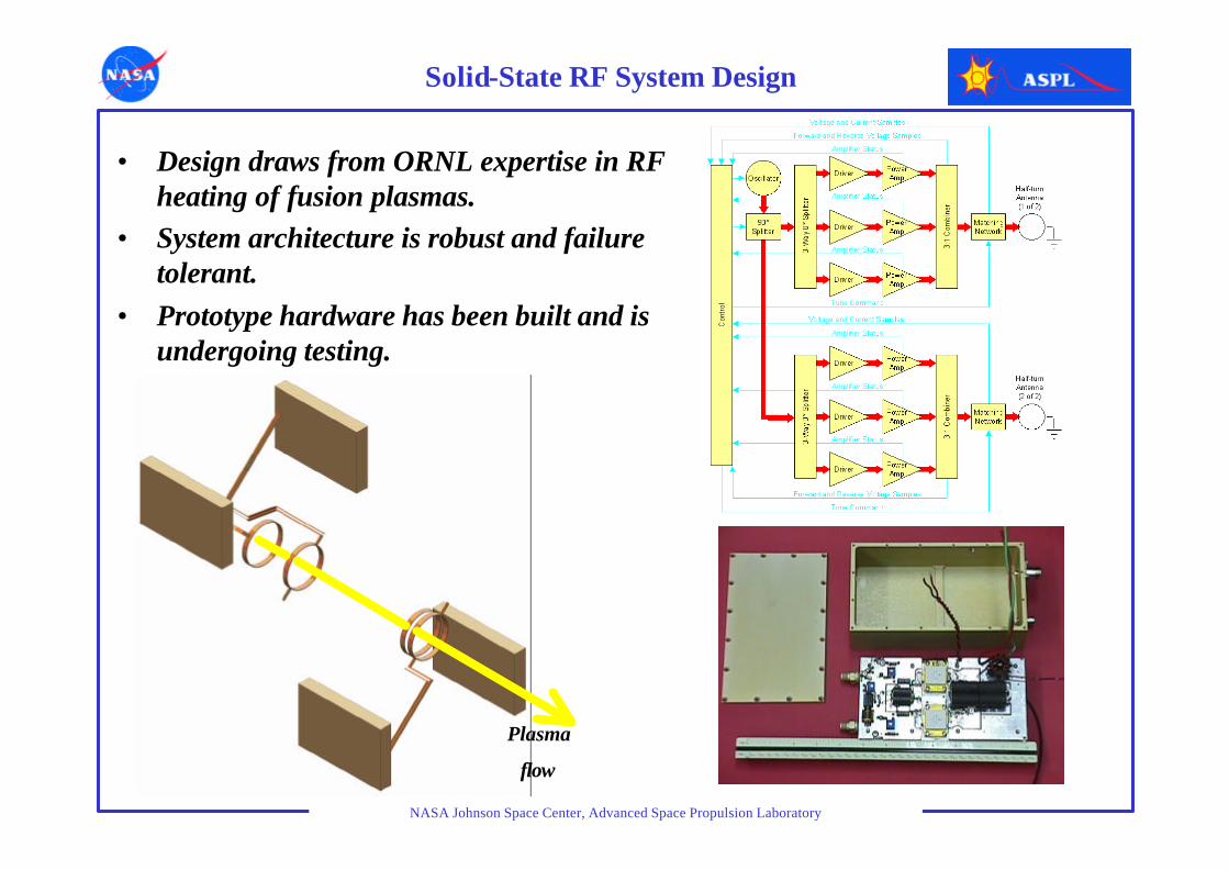
Solid-State RF System Design
• Design draws from ORNL expertise in RF heating of fusion plasmas.
• System architecture is robust and failure tolerant.
• Prototype hardware has been built and is undergoing testing.
Plasma
flow
NASA Johnson Space Center, Advanced Space Propulsion Laboratory
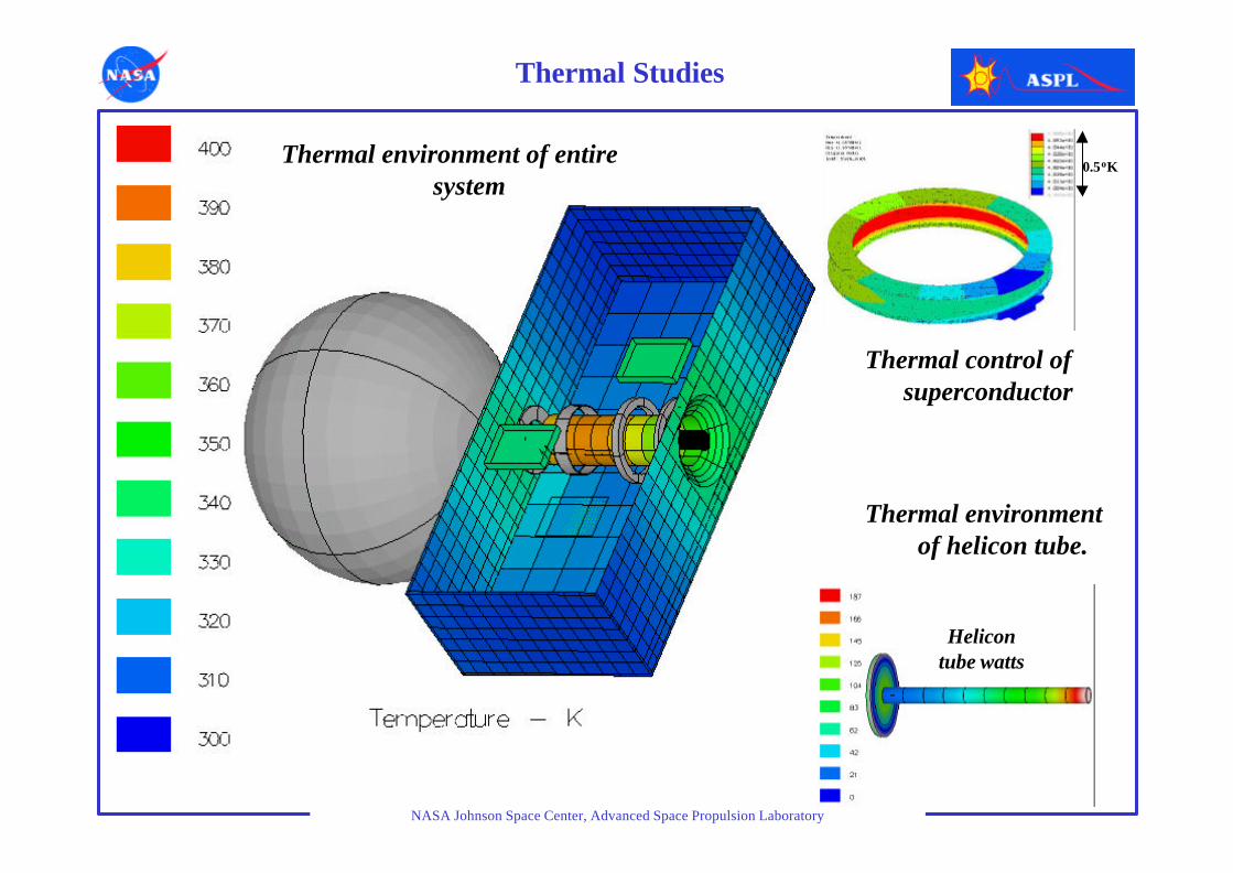
Thermal Studies
Helicon tube watts
Thermal environment of entire system
Thermal control of superconductor
Thermal environment of helicon tube.
0.5oK

NASA Johnson Space Center, Advanced Space Propulsion Laboratory
VX-10 Development &Testing

NASA Johnson Space Center, Advanced Space Propulsion Laboratory
5 kg superconducting magnet will replace 150 kg conventional LN2-cooled magnet
A vacuum chamber has been assembled for thermal testing of the superconducting magnet and cryocooler prior to integration into the VASIMR experiment.
Superconducting Magnet Technology

NASA Johnson Space Center, Advanced Space Propulsion Laboratory
Definitions
• Plasma: A super heated gas of electrically charged particles at temperatures greater than 10,000 oK. A magnetic field is used to guide and control the plasma (magnetoplasma.)
• VASIMR:Variable Specific Impulse Magnetoplasma Rocket.• RF: radio frequency power used to create and heat the plasma in the
VASIMR.• Helicon: 1st stage of VASIMR, is a high density plasma source, working
with RF power to breakdown the propellant gas and produce the plasma.• ICRH: ion cyclotron resonance heating, is the mechanism by which RF
waves further heat the plasma in the VASIMR 2nd stage. They do so by resonating with the natural cyclotron motion of the ions in the magnetic field.
• Bekuo: means “Star or Shooting Star” in the language of the Bri-Bri Indians of Costa Rica, descendants of the Maya. The name honors the native American civilizations, our earliest scientists and astronomers.
NASA Johnson Space Center, Advanced Space Propulsion Laboratory
VASIMR Primer
The VASIMR system is a high power, electrothermal plasma rocket featuring a very high specific impulse (Isp) and a variable exhaust. Its unique architecture allows in-flight mission-optimization of thrust and Isp to enhance performance and reduce trip time. VASIMR consists of three major magnetic stages where plasma is respectively injected, heated and expanded in a magnetic nozzle. The magnetic configuration is called an asymmetric mirror. The 1st stage handles the main injection of propellant gas and the ionization subsystem; the 2nd stage acts as an amplifier to further heat the plasma. The 3rd stage is a magnetic nozzle which converts the plasma energy into directed momentum. The magnetic field insulates nearby structures from the high plasma temperature (>1,000,000 oK.) It is produced by high temperature superconductors cooled mainly by radiation to deep space. Some supplemental cooling from the cryogenic propellants ( hydrogen, deuterium, helium or mixtures of these) may also be used.The system is capable of high power density, as the plasma energy is delivered by wave action, making it electrodeless and less susceptible to component erosion. Plasma production is done in the 1st stage by a helicon discharge, while additional plasma heating is accomplished in the 2nd stage by the process of ion cyclotron resonance.