pdmg1000 walk-behind power trowel owner’s manual · 2.4.3 do not test for spark on...
TRANSCRIPT

PDMG1000WALK-BEHIND POWER TROWEL
Owner’s Manual
This manual provides information regarding the operation and maintenance of these products. We have made every effort to ensure the accuracy of the information in this manual. We reserve the right to change this product at any time without prior notice.
Please keep this manual available to all users during the entire life of the power trowel.

TABLE OF CONTENTS
1. Foreword ...................................................................................................3
2. Safety Information..................................................................................... 4
2.1 Laws Pertaining to Spark Arrestors ...................................................................... 4
2.2 Operating Safety .............................................................. .................................... 5
2.3 Operator Safety while using Internal Combustion Engines .... .............................. 6
2.4 Service Safety ....................................................................... ............................... 7
2.5 Label Locations .................................................................... ................................ 8
2.6 Safety and Information Labels ............................................... ............................... 9
3. Technical Data .........................................................................................14
3.1 Engine ........................................................ ..........................................................16
3.2 Sound and Vibration Data ........................ ............................................................ 21
4. Operation................................................................................................... 22
4.1 Application ...................................... ......................................................................22
4.2 New Machine Set-up ...................... ..................................................................... 22
4.3 Recommended Fuel ........................ .................................................................... 22
4.4 Installing Blades .............................. .................................................................... 23
4.5 Installing and Adjusting Handles ...... ................................................................... 24
4.6 Controls ......................................... ...................................................................... 26
4.7 Engine switch handle ................................... ........................................................ 26
4.8 Before Starting................................... .................................................................... 27
4.9 To Start.............................. .................................................................... ................27
4.10 To Stop ............................. ................................................................... ................28
4.11 Engine Control Module ..................... ............................................................. ….31
4.12 Operation .......................................... ................................................................. 32

4.13 Braking System ................................. ................................................................. 33
4.14 Pitch Adjustment ................................ ................................................................ 34
5. Maintenance ...............................................................................................35
5.1 Periodic Maintenance Schedule ................ ............................................. ............35
5.2 Engine Oil ................................................... .................. ......................................37
5.3 Air Cleaner ............................................... .......... ........... .....................................39
5.4 Spark Plug ................................................. ...........................................................41
5.5 Cleaning Sediment Cup ................. ........................ .............. ..............................42
5.6 Adjusting Idle Speed .................... ......... ..............................................................44
5.7 Carburetor Adjustment .................. ............... ....... ..............................................45
5.8 Belt Replacement ....................................... .........................................................46
5.9 Trowel Lubrication ...................................... .........................................................47
5.10 Optional Weights ..................................... ............................................................47
5.11 Lifting ....................................................... ............................................................48
5.12 Storage .................................................... ............................................................49
5.13 Troubleshooting ....................................... ...........................................................50
CALIFORNIA
Proposition 65 Warning:
Engine exhaust, some of its constituents, and certain vehicle components, contain or emit chemicals known to the State of California to cause cancer and birth defects or other reproductive harm.
1. Foreword
This manual provides information and procedures to safely operate and maintain the model. For your own safety and protection from injury, carefully read, understand and observe the safety instructions described in this manual.
Keep this manual or a copy of it with the machine. If you lose this manual or need an additional copy, please contact our Corporation. This machine is built with user safety in mind; however, it can present hazards if improperly operated and serviced. Follow operating instructions carefully! If you have questions about operating or servicing this equipment, please contact our Corporation.
The information contained in this manual was based on machines in production at the time of publication. We will reserves the right to change any portion of this information without notice.
2. Safety Information
This manual contains DANGER, WARNING, CAUTION, and NOTE callouts which must be followed to reduce the possibility of personal injury, damage to the equipment, or improper service.
This is the safety alert symbol. It is used to alert you to potential personal injury hazards. Obey all safety messages that follow this symbol to avoid possible injury or death.
DANGER indicates an imminently hazardous situation which, if not avoided, will result in death or serious injury.
WARNING indicates a potentially hazardous situation which, if not avoided, could result in death or serious injury.

CAUTION indicates a potentially hazardous situation which, if not avoided, may result in minor or moderate injury.
CAUTION: Used without the safety alert symbol, CAUTION indicates a potentially hazardous situation which, if not avoided, may result in property damage.
Note: Contains additional information important to a procedure.
2.1 Laws Pertaining to Spark Arrestors
Notice: State Health Safety Codes and Public Resources Codes specify that in certain locations spark arresters be used on internal combustion engines that use hydrocarbon fuels. A spark arrester is a device designed to prevent accidental discharge of sparks or flames from the engine exhaust. Spark arresters are qualified and rated by the United States Forest Service for this purpose.
In order to comply with local laws regarding spark arresters, consult the engine distributor or the local Health and Safety Administrator.
2.2 Operating Safety
WARNING: Familiarity and proper training are required for the safe operation of equipment. Equipment operated improperly or by untrained personnel can be dangerous. Read the operating instructions contained in both this manual and the engine manual and familiarize yourself with the location and proper use of all controls. Inexperienced operators should receive instruction from someone familiar with the equipment before being allowed to operate the machine.
2.2.1 NEVER allow anyone to operate this equipment without proper training. People operating this equipment must be familiar with the risks and hazards associated with it.
2.2.2 NEVER touch the engine or muffler while the engine is on or immediately after it has been turned off. These areas get hot and may cause burns.
2.2.3 NEVER use accessories or attachments that are not recommended by us. Damage to equipment and injury to the user may result.
2.2.4 NEVER leave machine running unattended.
2.2.5 NEVER operate the machine with the beltguard missing. Exposed drive belt and pulleys create potentially dangerous hazards that can cause serious injuries.
2.2.6 NEVER operate this machine in applications for which it is not intended.

2.2.7 NEVER use the trowel around pop-ups in the concrete that are lower than the lowest ring on the ring guard.
2.2.8 ALWAYS wear protective clothing appropriate to the job site when operating equipment.
2.2.9 ALWAYS wear hearing and eye protection when operating this machine.
2.2.10 ALWAYS remain aware of moving parts and keep hands, feet, and loose clothing away from the moving parts of the equipment.
2.2.11 ALWAYS read, understand, and follow procedures in the Operator’s Manual before attempting to operate the equipment.
2.2.12 ALWAYS store the equipment properly when it is not being used. Equipment should be stored in a clean, dry location out of the reach of children.
2.2.13 ALWAYS close fuel valve on engines equipped with one when machine is not being operated.
2.2.14 ALWAYS operate machine with all safety devices and guards in place and in working order. DO NOT modify or defeat safety devices. DO NOT operate machine if any safety devices or guards are missing or inoperative.
2.2.15 ALWAYS be sure operator is familiar with proper safety precautions and operation techniques before using machine.
2.2.16 ALWAYS test the function of the engine control module before operating the trowel. DO NOT operate the trowel if the engine control module is not functioning properly.
2.3 Operator Safety while using Internal Combustion Engines
DANGER: Internal combustion engines present special hazards during operation and fueling. Read and follow the warning instructions in the engine owner’s manual and the safety guidelines below. Failure to follow the warnings and safety guidelines could result in severe injury or death.
2.3.1 DO NOT run the machine indoors or in an enclosed area such as a deep trench unless adequate ventilation, through such items as exhaust fans or hoses, is provided. Exhaust gas from the engine contains poisonous carbon monoxide gas; exposure to carbon monoxide can cause loss of consciousness and may lead to death.
2.3.2 DO NOT smoke while operating the machine.
2.3.3 DO NOT smoke when refueling the engine.
2.3.4 DO NOT refuel a hot or running engine.
2.3.5 DO NOT refuel the engine near an open flame.
2.3.6 DO NOT spill fuel when refueling the engine.
2.3.7 DO NOT run the engine near open flames.
2.3.8 ALWAYS refill the fuel tank in a well-ventilated area.
2.3.9 ALWAYS replace the fuel tank cap after refueling.
2.4 Service Safety
WARNING: Poorly maintained equipment can become a safety hazard! In order for the equipment to operate safely and properly over a long period of time, periodic maintenance and occasional repairs are necessary.
2.4.1 DO NOT attempt to clean or service the machine while it is running. Rotating parts can cause severe injury.
2.4.2 DO NOT crank a flooded engine with the spark plug removed on gasoline-powered engines. Fuel trapped in the cylinder will squirt out the spark plug opening.
2.4.3 DO NOT test for spark on gasoline-powered engines if the engine is flooded or the smell of gasoline is present. A stray spark could ignite the fumes.
2.4.4 DO NOT use gasoline or other types of fuels or flammable solvents to clean parts, especially in enclosed areas. Fumes from fuels and solvents can become explosive.
2.4.5 DO NOT remove blades while the machine is hanging overhead.
2.4.6 ALWAYS support the machine securely before changing blades.
2.4.7 ALWAYS keep the area around the muffler free of debris such as leaves, paper, cartons, etc. A hot muffler could ignite the debris and start a fire.
2.4.8 ALWAYS replace worn or damaged components with spare parts designed and recommended by our Corporation.
2.4.9 ALWAYS disconnect the spark plug on machines equipped with gasoline engines, before servicing, to avoid accidental start-up.
2.4.10 ALWAYS keep the machine clean and labels legible. Replace all missing and hard-to-read labels. Labels provide important operating instructions and warn of dangers and hazards.
2.4.11 ALWAYS handle blades carefully. The blades can develop sharp edges which can cause serious cuts.
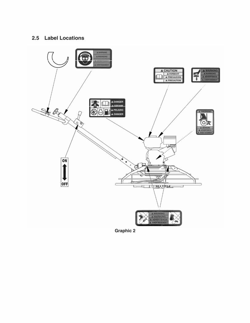
2.5 Label Locations
Graphic 2
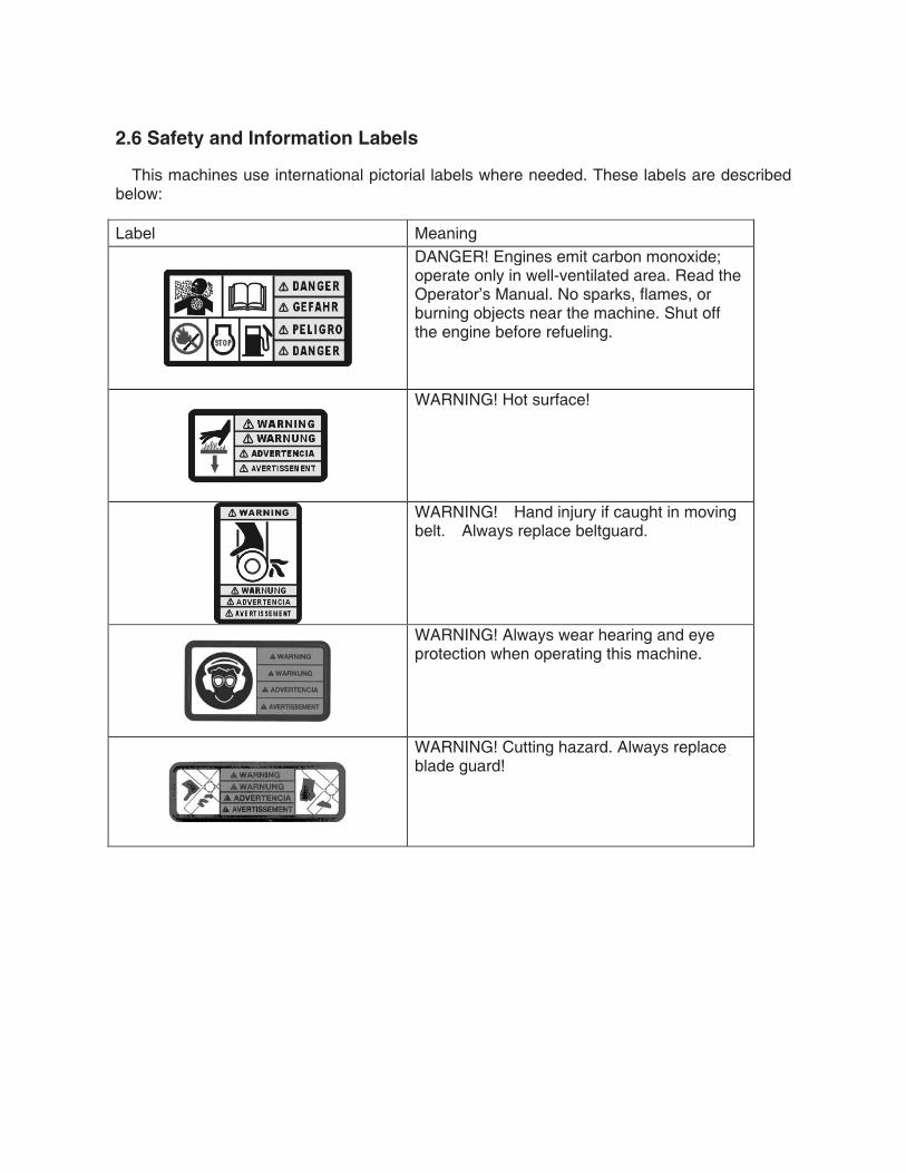
2.6 Safety and Information Labels
This machines use international pictorial labels where needed. These labels are described below:
Label Meaning
DANGER! Engines emit carbon monoxide; operate only in well-ventilated area. Read the Operator’s Manual. No sparks, flames, or burning objects near the machine. Shut off the engine before refueling.
WARNING! Hot surface!
WARNING! Hand injury if caught in moving belt. Always replace beltguard.
WARNING! Always wear hearing and eye protection when operating this machine.
WARNING! Cutting hazard. Always replace blade guard!

Label Meaning
WARNING Remove pan from trowel before lifting machine overhead. Pans can fall and cause death or serious injury if a person is hit.(Located on top side of float pan.)
Variable speed throttle
CAUTION Read and understand the supplied Operator’s Manuals before operating this machine . Fail-ure to do so increases the risk of injury to your-self or others.
Engine engine switch handle: Press to stop engine

Label Meaning
Open the fuel flow valve.
Close the choke.
Turn engine switch to “ON” position.
Turn engine key switch to “NO” position.
Place throttle in the IDLE position.
Pull the rewind starter
Open the choke

Label Meaning
Turn engine switch to “OFF” position.
Turn engine key switch to “OFF” position.
Close the fuel flow valve.

3. Technical Data
3.1 Engine
Item No. PDMG1000
Engine Model 168F
Rated Power kW (Hp) 4.8(6.5) @ 3600rpm
Spark Plug NGK BPR 6ES , F7RTC
Electrode Gap mm (in.) 0.7 – 0.8 (0.028 – 0.031)
Engine Speed - full load rpm 3800 ± 100
Engine Speed - idle rpm 1450 ± 100
Clutch engagement rpm 1800
Valve Clearance (cold) intake: exhaust:
mm (in.) 0.15 (0.006) 0.20 (0.008)
Air Cleaner type Dual element
Engine Lubrication oil grade SAE 10W30 SG or SF
Engine Oil Capacity L (oz.) 0.6 (20)
Fuel type Regular unleaded gasoline
Fuel Tank Capacity L qts.) 3.6 (3.8)
Fuel Consumption L (qts.) /hr 1.8 (1.9)
Running time hr. 2
Trowel Diameter mm (in.) 960 38
Trowel Rotor rpm 60-140
Gear Box Lubrication L (oz.) 0.62 (21) Pitch Range degrees 0-15
Dimensions mm (in) 1040X1040X620(41X41X24.4) Weight kg (lbs.) 98/(215)
3.2 Sound and Vibration Data
The required sound specification, Paragraph 1.7.4.f of 89/392/EEC Machinery Directive, is:
the sound pressure level at operator’s location (LpA) : 103 dB(A) the guaranteed sound power level (LWA) = 89dB(A) These sound values were determined according to ISO 3744 for the sound power level
(LWA) and ISO 6081 for the sound pressure level (LpA) at the operator’s location.
The weighted effective acceleration value, determined according to ISO 8662 Part 1, is: 5.3 m/s2.
The sound and vibration specifications were obtained with the unit operating on cured concrete at full engine speed.
4. Operation
4.1 Application
This trowel is a modern, high production machine intended for floating and finishing freshly poured concrete slabs. The machine's good balance, adjustable handle, and easily reached controls add to operator comfort and productivity. An automatic stop sensor provides added operator safety. Finishing rates will depend on operator skill and job conditions.
DO NOT use this machine for any application other than troweling concrete.
4.2 New Machine Set-up
Trowels are shipped from the factory with the handle removed. Follow instructions on Installing Blades and Installing and Adjusting Handles when setting up new machines or when installing new handles and blades.
4.3 Recommended Fuel
The engine requires regular grade unleaded gasoline. Use only fresh, clean gasoline. Gasoline containing water or dirt will damage fuel system. Consult engine owner’s manual for complete fuel specifications.
4.4 Installing Blades
See Graphic 2
There are four types of blades available for the trowels. Float pans are large "pizza pan" style blades, which hook on over finish or combination blades and are available for the 36" machines only. Float blades are available for all machines and clip on over finish or combination blades. Both are used in the earliest stages of work, and are not pitched.
Finish blades are used in the final stages of working, and are progressively pitched to burnish the concrete.
Combination blades can be used throughout the concrete working process. They are used in place of float blades or pans and finish blades.
Note: Trowel blades must NOT be interchanged, i.e., do NOT put larger diameter blades on a smaller diameter trowel.
4.4.1 Finish blades are flat on both edges and can be installed in either direction.
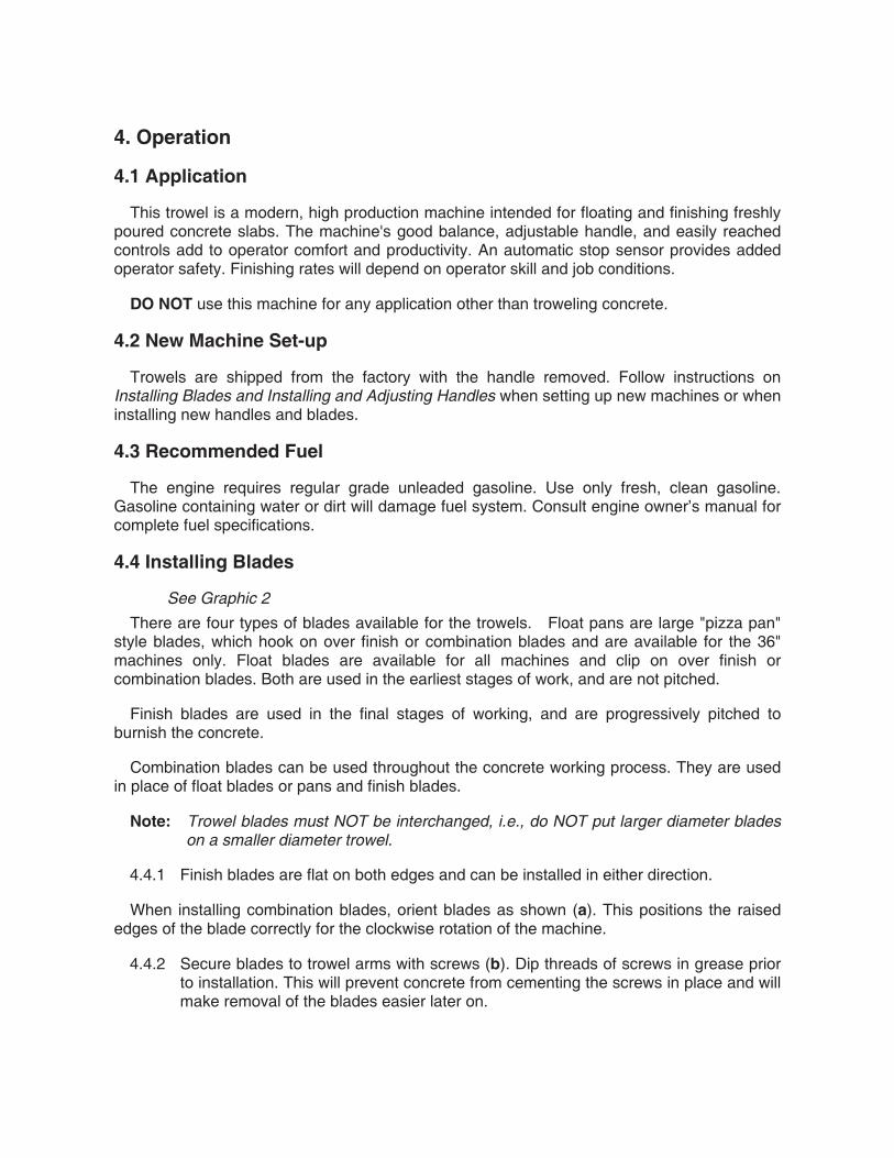
When installing combination blades, orient blades as shown (a). This positions the raised edges of the blade correctly for the clockwise rotation of the machine.
4.4.2 Secure blades to trowel arms with screws (b). Dip threads of screws in grease prior to installation. This will prevent concrete from cementing the screws in place and will make removal of the blades easier later on.
4.4.3 Plug the remaining threaded holes in the blade brace with plastic plugs (c) to prevent them from filling with concrete.
WARNING: Do not lift the trowel overhead with a float pan attached, as the pan could fall off and strike personnel working in the vicinity.
Graphic 2
4.5 Installing and Adjusting Handles
See Graphic 3,4
On new machines the pipe handle comes assembled with the pitch control (Twist or Pro-Shift®) (c), engine switch handle (b), throttle (a), screws (g), and nut (m).
To install the pipe handle assembly:
4.5.1 On machines with an adjustable handle, position the handle by loosening the knob (d) and adjusting the handle up or down to suit the operator. Tighten the knob to secure the handle in position.
4.5.2 Pull the pitch control cable (j) from bottom end of the tube and remove the nut from the cable.
4.5.3 Thread the cable through the handle base (f) and over the pulley (h) as shown.
4.5.4 Attach the pipe handle to the handle base with two M8x65 screws (g). Torque the screws to 25 Nm (18 ft lbs.).
4.5.5 Push the handle all the way forward (away from the operator) OR turn the twist pitch control handle counterclockwise as far as possible. Connect the cable to the fork (k) as shown and adjust the cable nut (m) so the cable is snug and the trowel blades lay flat (0° pitch).
4.5.6 Move throttle (a1) to idle position. Remove air cleaner cover. Feed cable through clamp on recoil cover. Connect throttle cable to engine throttle bracket by placing z-bend through hole in throttle plate. Clamp cable into throttle casing bracket.

Replace air cleaner cover.
4.5.7 Connect electrical wire on handle to both ends of the engine wire. See handle instruction sheet for additional detail on installation.
Note: On machines with the engines, do not connect wires in bag to wires in handle.
Graphic 3
Graphic 4

4.6 Controls
See Graphic 3
Ref. Description Ref. Description
a Throttle d Handle height adjustment(if equipped)
b Engine switch handle
c Twist pitch control or pitch control
4.7 Engine Switch Handle
See Graphic 3
When the engine switch handle (b) is pressed, the engine will shut off.
To prevent uncontrolled spinning of the trowel, the engine control module is designed to shutoff the engine under certain conditions. For example, if the operator loses his/her grip on the trowel, the engine control module will sense that the machine is spinning and shut off the engine. The momentum of the spinning trowel will engage the brake and stop the handle from spinning past 270°.
4.8 Before Starting
Before starting trowel, check the following:
oil level in engine
oil level in gearbox
fuel level
condition of air filter
condition of fuel lines
condition of trowel arms and blades
condition of ring guard
label descriptions
handle height to suit operator
4.9 To Start

See Graphic 3, 5 4.9.1 Open fuel valve by moving lever to the right (g1).
Note: If engine is cold, move choke lever to closed position (i1). If engine is hot, set choke to open position (i2).
4.9.2 Turn engine switch to “ON” (h1).
4.9.3 Move the throttle lever to the idle position (a1).
Note: Start engine with throttle in the idle position. If the engine is started when the throttle is not in the idle position, the engine should not start. This is a feature of the engine control module that prevents wide open throttle startup.
4.9.4 Pull starter rope (j).
WARNING: Do not place foot on the ring guard when starting the engine, as severe injury can occur if foot slips through the ring guard as the blades start to spin.
Note: If the engine oil is low, the engine will not start. If engine does not start, check the oil level and add oil as needed.
4.9.5 Open choke as engine warms (i2).
4.9.6 Open throttle (a2) to operate trowel. Adjust blade RPM with throttle speed to suit conditions.
Graphic 5
4.10 To Stop
See Graphic 3, 5
4.10.1 Reduce engine RPM to idle by moving the throttle lever to idle position (a1).
4.10.2 Push the engine switch handle (b).
4.10.3 Turn engine switch to “OFF” (h2).
4.10.4 Close fuel valve by moving lever to the left (g2).

4.11 Engine Control Module
To test the engine control module, start the machine and jerk the handle to the right. The engine should stop. If the engine does not stop, repeat the jerking motion until the engine stops. If the engine does not shut off, push the engine switch handle and turn the engine off. DO NOT operate the machine until the engine control module is replaced.
WARNING: DO NOT operate the trowel if the engine control module is disconnected or not functioning properly.
4.12 Operation
See Graphic 6
WARNING: ALWAYS test the function of the engine control module before operating the trowel. DO NOT operate the trowel if the engine control module is not functioning properly.
Choose correct blade type and attach blades to trowel arms. Do not mix float or finish blades with combination blades.
Note: When operating on soft concrete, do not let trowel stand in one spot too long. Always lift trowel from slab when operation is complete.
Note: “Left” and “Right” references are made from the operator's position.
4.12.1 Adjust handle height to suit operator. See Installing and Adjusting Handles.
CAUTION: Do not attempt to adjust handle height on the trowel while it is running.
4.12.2 Start engine and engage blades by increasing engine speed. Set speed with throttle control on handle bar to appropriate speed for job conditions.
4.12.3 To move trowel forward twist handle clockwise (a).
4.12.4 To move backward twist handle counterclockwise (b).
4.12.5 To move to the left lift up slightly on the handle (c).
4.12.6 To move to the right press down slightly on the handle (d).
4.12.7 Clean trowel after each use to remove concrete splatter.
WARNING: Allow the muffler to cool before cleaning or servicing the machine. A hot muffler could ignite the fuel and start a fire.

It is recommended that each set of work passes be at 90° to the previous set of work passes. This will help prevent the creation of valleys in the slab surface.
For example, in the illustration, the second set of work passes (2) is 90° to the first set of work passes (1).
WARNING: Personnel other than the trowel operator should not be allowed in the work area, as severe injury can occur from contact with operating trowel blades.
Do not attempt to clean, service or perform adjustments on the trowel while it is running.
Graphic 6
4.13 Braking System
The braking system of the trowel is spring loaded. The brake is engaged anytime the input shaft of the gearbox is not rotating and/or there is no resistance placed against the blades of the trowel. The brake is released when the input shaft is rotated and is shifted out from its seated position. This is accomplished when the gear on this shaft rotates, working against the output shaft gear, forcing the shaft out. If there is no or low resistance against the blades, the brake may not release as it is the resistance against the blades that allows the brake to release. If the machine is suspended or on a highly polished, slippery surface, the brake will
not release and could cause belt slippage.
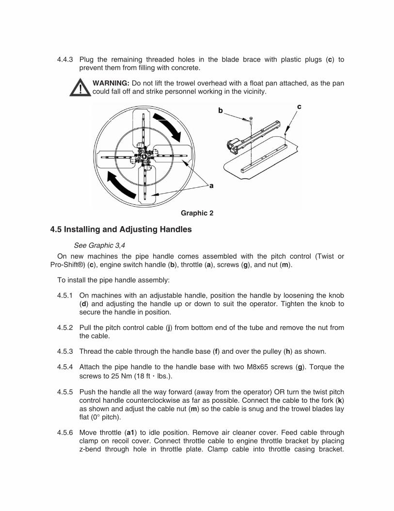
4.14 Pitch Adjustment
See Graphic 7
To adjust blade pitch (angle):
Turn the pitch adjusting knob (c) clockwise to increase pitch and counterclockwise to decrease pitch.
A B C
1
2
3
4
Graphic 7
Ref. B = Working condition of concrete C = Suggested working pitch
1 Wet surface working stage Flat (no pitch)
2 Wet to plastic working stage Slight pitch (5°)
3 Plastic working stage Additional pitch (10°)
4 Semi-hard working stage to hard finishing stage (burnishing)
Maximum pitch (15-30°)
For final finishing stages, it is sometimes desirable to add weights to the trowel guard rings
to increase the burnishing force. we supplies weight kits for this purpose.

5. Maintenance
5.1 Periodic Maintenance Schedule
The chart below lists basic machine and engine maintenance. Refer to the engine manufacturer’s Operator’s Manual for additional information on engine maintenance.
Daily After first
20 hrs. Every 50 hrs.
Every 100 hrs.
Every 300 hrs.
Check fuel level. •
Check engine oil level. •
Inspect fuel lines. •
Inspect air filter. Replace as needed. •
Check external hardware. •
Clean trowel after each use to remove concrete splatter.
•
Clean air cleaner elements. •
Change engine oil. • •
Check drive belt. •
Clean sediment cup. •
Check and clean spark plug. •
Check and adjust valve clearances. •
Perform initially after first 20 hours of operation.
Maintenance, replacement or repair of emission control devices and systems may be performed by any repair establishment or individual.
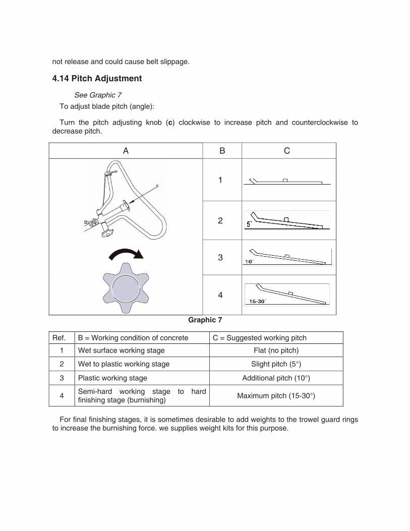
5.2 Engine Oil
See Graphic 8
5.2.1 Drain oil while the engine is still warm.
5.2.2 Remove the oil fill plug (a) and drain cap (b) to drain oil.
Note: In the interests of environmental protection, place a plastic sheet and a container under the machine to collect any liquid which drains off. Dispose of this liquid in accordance with environmental protection legislation.
5.2.3 Install drain cap.
5.2.4 Fill the engine crankcase with recommended oil up to the level of the plug opening (c). See Technical Data for oil quantity and type.
5.2.5 Install the oil filler plug.
Graphic 8
5.3 Air Cleaner
See Graphic 9
The engine is equipped with a dual element air cleaner. Service air cleaner frequently to prevent carburetor malfunction.
CAUTION: NEVER run engine without air cleaner. Severe engine damage will occur.
WARNING: NEVER use gasoline or other types of low flash point solvents for cleaning the air cleaner. A fire or explosion could result.
To service:
5.3.1 Remove air cleaner cover (a). Remove both elements and inspect them for holes or tears. Replace damaged elements.
5.3.2 Wash foam element (b) in solution of mild detergent and warm water. Rinse thoroughly in clean water. Allow element to dry thoroughly. Soak element in clean engine oil and squeeze out excess oil.
5.3.3 Tap paper element (c) lightly to remove excess dirt. Replace paper element if it appears heavily soiled.

Graphic 9
5.4 Spark Plug
See Graphic 10
Clean or replace the spark plug as needed to ensure proper operation. Refer to the engine owner’s manual.
WARNING: The muffler becomes very hot during operation and remains hot for awhile after stopping the engine. Do not touch the muffler while it is hot.
Note: Refer to the Technical Data for the recommended spark plug type and the electrode gap setting.
5.4.1 Remove the spark plug and inspect it.
5.4.2 Replace the spark plug if the insulator is cracked or chipped.
5.4.3 Clean the spark plug electrodes with a wire brush.
5.4.4 Set the electrode gap (a).
5.4.5 Tighten the spark plug securely.
CAUTION: A loose spark plug can become very hot and may cause engine damage.
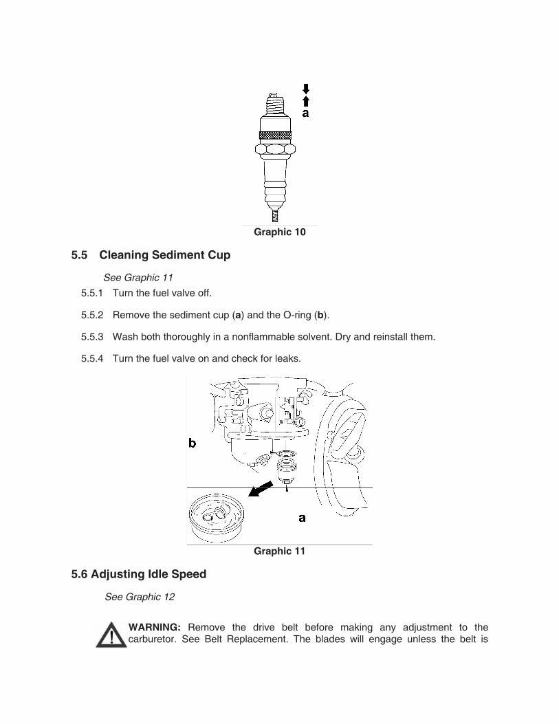
Graphic 10
5.5 Cleaning Sediment Cup
See Graphic 11
5.5.1 Turn the fuel valve off.
5.5.2 Remove the sediment cup (a) and the O-ring (b).
5.5.3 Wash both thoroughly in a nonflammable solvent. Dry and reinstall them.
5.5.4 Turn the fuel valve on and check for leaks.
Graphic 11
5.6 Adjusting Idle Speed
See Graphic 12
WARNING: Remove the drive belt before making any adjustment to the carburetor. See Belt Replacement. The blades will engage unless the belt is
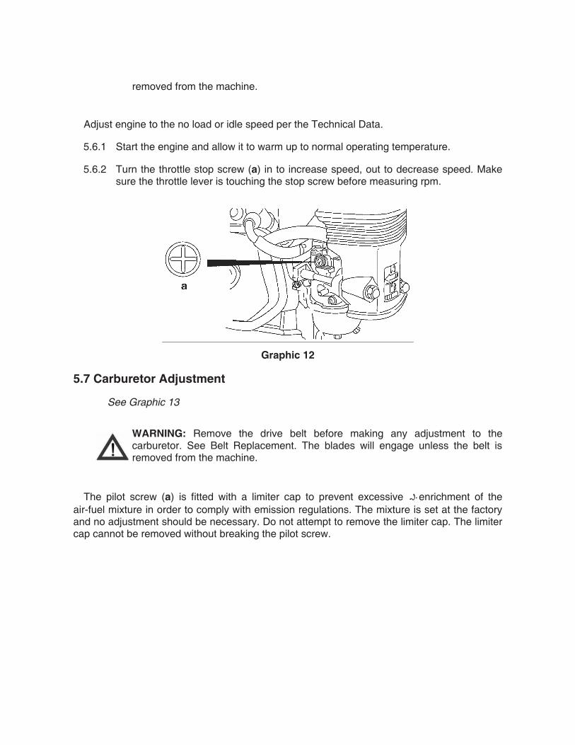
removed from the machine.
Adjust engine to the no load or idle speed per the Technical Data.
5.6.1 Start the engine and allow it to warm up to normal operating temperature.
5.6.2 Turn the throttle stop screw (a) in to increase speed, out to decrease speed. Make sure the throttle lever is touching the stop screw before measuring rpm.
Graphic 12
5.7 Carburetor Adjustment
See Graphic 13
WARNING: Remove the drive belt before making any adjustment to the carburetor. See Belt Replacement. The blades will engage unless the belt is removed from the machine.
The pilot screw (a) is fitted with a limiter cap to prevent excessive enrichment of the air-fuel mixture in order to comply with emission regulations. The mixture is set at the factory and no adjustment should be necessary. Do not attempt to remove the limiter cap. The limiter cap cannot be removed without breaking the pilot screw.
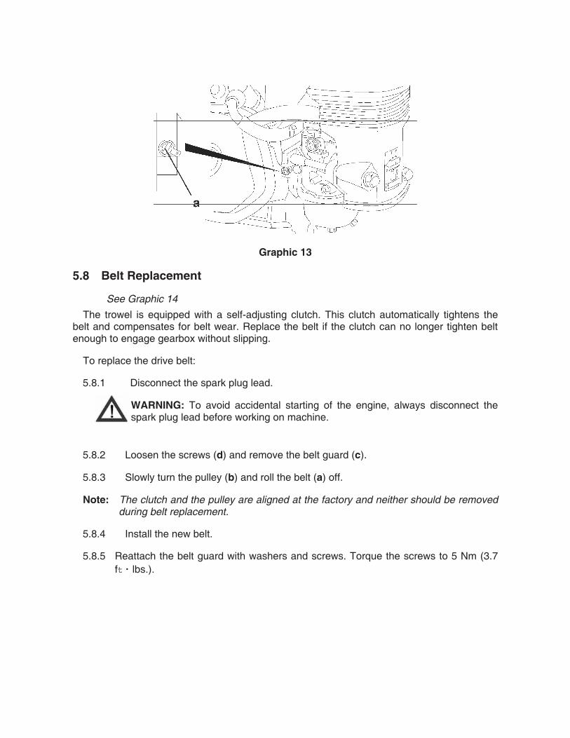
Graphic 13
5.8 Belt Replacement
See Graphic 14
The trowel is equipped with a self-adjusting clutch. This clutch automatically tightens the belt and compensates for belt wear. Replace the belt if the clutch can no longer tighten belt enough to engage gearbox without slipping.
To replace the drive belt:
5.8.1 Disconnect the spark plug lead.
WARNING: To avoid accidental starting of the engine, always disconnect the spark plug lead before working on machine.
5.8.2 Loosen the screws (d) and remove the belt guard (c).
5.8.3 Slowly turn the pulley (b) and roll the belt (a) off.
Note: The clutch and the pulley are aligned at the factory and neither should be removed during belt replacement.
5.8.4 Install the new belt.
5.8.5 Reattach the belt guard with washers and screws. Torque the screws to 5 Nm (3.7 f lbs.).
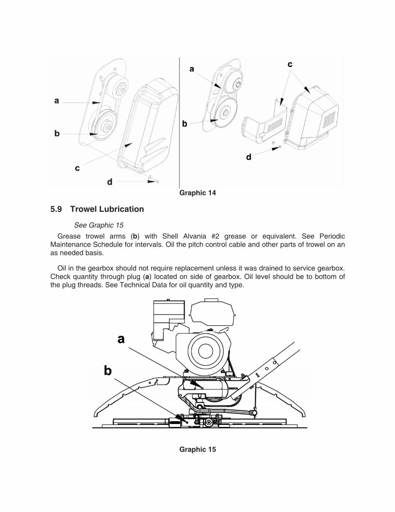
Graphic 14
5.9 Trowel Lubrication
See Graphic 15
Grease trowel arms (b) with Shell Alvania #2 grease or equivalent. See Periodic Maintenance Schedule for intervals. Oil the pitch control cable and other parts of trowel on an as needed basis.
Oil in the gearbox should not require replacement unless it was drained to service gearbox. Check quantity through plug (a) located on side of gearbox. Oil level should be to bottom of the plug threads. See Technical Data for oil quantity and type.
Graphic 15

5.10 Optional Weights
To install optional weights, place equal number of weights in both front and rear of guard ring in designated area. Tighten screw to keep weights in place.
WARNING: Under no circumstances should any object be used as additional weight other than the weights recommended by us. The use of unauthorized weights could lead to personal injury or machine damage.
5.11 Lifting
See Graphic 16
See Technical Data for the weight of the machine.
To lift the machine manually:
5.11.1 Stop engine.
5.11.2 Obtain a partner and plan the lift.
5.11.3 Balance the weight between the partners and lift the machine by the guard ring (a).
WARNING: To reduce risk of back injury while lifting, keep your feet flat on ground and shoulder width apart. Keep your head up and back straight.
Graphic 16
5.12 Storage
If trowel is being stored for more than 30 days:
Change engine oil.
Drain fuel from engine.

Remove spark plug and pour 15 ml (½ ounce) of SAE 30 engine oil into the cylinder. Replace spark plug and crank engine to distribute oil. Refer to engine manual.
Clean dirt from cylinder, cylinder head fins, blower housing, rotating screen, and muffler areas.
To save space, place handle in its storage position.
Cover trowel and engine and store in a clean, dry area.
5.13 Troubleshooting
Problem / Symptom Reason / Remedy
Trowel does not develop full speed.
• Remove deposits built up in engine cylinder and engine head.
• Engine speed too low. Adjust speed. • Clean or replace air filter. • Clean debris from moving parts and trowel blades. • In cold weather, warm engine in idle 3 or 4 minutes. • Check throttle lever and cable for proper operation.
Engine runs; poor trowel operation.
• Check belt for wear or damage. • Check clutch for wear or damage. • Clean debris from moving parts and trowel arms.
Engine does not start or runs erratically.
• Check fuel level. Open fuel valve. • Clean air filter. • Check/replace spark plug. • Check in-line fuel filter. • Check engine oil level. • Check engine switch handle to stop position. • Check that throttle is in idle position when starting
machine.
Trowel handle tends to rotate when idling.
• Check engine idle speed. It may be too high. • Belt alignment may be off.

SAFETY ALERT SYMBOL
This Safety Alert Symbol means ATTENTION is required!
The Safety Alert Symbol identifies important safety messages on machines, safety signs, in manuals or elsewhere. When you see this symbol, be alert to the possibility of personal injury or death. Follow the instructions in the safety message.
Why is SAFETY important to YOU?
3 BIG REASONS
• Accidents KILL or DISABLE
• Accidents COST
• Accidents CAN BE AVOIDED
FOREWORD
This safety manual is intended to point out some of the basic situations which may be encountered during the normal operation and maintenance of your walk-behind or ride-on concrete power trowel and to suggest possible ways of dealing with these conditions.
Additional precautions may be necessary, depending on application and attachments used and conditions at the work site or in the maintenance area.
The trowel manufacturer has no direct control over machine application, operation, inspection, lubrication, or maintenance. Therefore, it is your responsibility to use good safety practices in these areas.
Do not use the trowel for any purpose other than its intended purposes or applications.
The information provided in this manual supplements the specific information about your machine and its application that is contained in the manufacturer’s manual(s).
Other information which may affect the safe operation of your machine may be displayed on safety signs, or in insurance requirements, employer’s safety programs, safety codes, local, state/provincial, and federal laws, rules, and regulations.
If you do not understand any of this information, or if errors or contradictions seem to exist, consult with your supervisor before operating your trowel!
IMPORTANT: If you do not have the manufacturer’s manual(s) for your particular machine, get a replacement manual from your employer, equipment dealer, or manufacturer of your machine. Keep this safety manual and the manufacturer’s manual(s) accessible to the operator and maintenance personnel.
A WORD TO THEUSER
Remember that YOU are the key to safety. Good safety practices not only protect you but also protect the people around you. It is your responsibility to study this manual and the manufacturer’s manual(s) for your specific machine before operating your machine. Make them a working part of your safety program. Keep in mind that this safety manual is written for concrete power trowels only. Practice all other usual and customary safe working precautions, and above all –
REMEMBER – SAFETY IS UP TO YOU
YOU CAN PREVENT SERIOUS
INJURY OR DEATH
FOLLOW A SAFETY PROGRAM
EQUIPMENT/CLOTHING
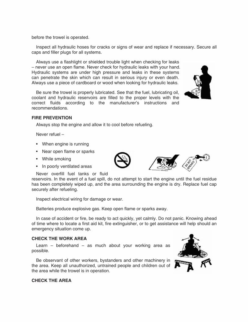
Consult your supervisor for specific instructions on a job, and the personal safety equipment required. For instance, you may need:
• Hard Hat
• Heavy Gloves
• Eye Protection
• Ear Protectors
• Safety Shoes
• Dust Mask or Respirator
Do not wear loose clothing or any accessory – flopping cuffs, dangling neckties and scarves, or jewelry – that can catch in moving parts.
DUST PRECAUTION
Some dust created by construction activities may cause silicosis or respiratory harm.
Your risk of exposure varies depending on how often you do this type of work. To reduce your risk, work in a well ventilated area, use a dust control system, and wear approved personal safety equipment such as a dust/particle respirator designed to filter out microscopic particles.
PREPARE FOR SAFE OPERATION
LEARN TO BE SAFE

• Read the operator’s manual. If one has not been provided, get one and study it before operating the equipment.
• Learn the location and understand the functions of all controls before attempting to operate the equipment.
• Know the meaning of all identification symbols on the controls and gauges.
• Check to determine that the manufacturer’s furnished safety warning labels are securely attached to the trowel and all warnings can clearly read. Replace labels and decals if they are missing or become worn or unreadable.
• Know the location and type of emergency shutdown control the trowel is equipped with.
• Never start or operate the trowel without protective guards and panels in place.
• Know the capabilities and limitations of the trowel.
SAFETY DEVICES
Know what safety devices your trowel is equipped with … and see that each item is securely in place and in operating condition.
For example:
• Emergency stop switch or other “Shut-Down” devices
• Guards, Shields & Panels
• Alarms or Warning Lamps
• Drain Covers, Plugs, and Caps
• Pressure Relief Devices
• Lights
PRE-OPERATIONAL CHECKS
Walk around the trowel. Carefully inspect for evidence of physical damage, such as cracks, bends, or deformation of plates and welds. Check for loose, broken or missing parts on the trowel, including brackets, vibration isolators, nuts and bolts. Hardware should be replaced with original equipment manufacturer’s (OEM) parts, and should be properly tightened to the manufacturer’s recommendations.
Remove all trash and debris from the trowel. Make sure oily rags, leaves, or other flammable material are removed and not stored on the trowel. Avoid potential fire hazards!
Clean all oil or grease from operator areas such as control handles, foot pedals, or platforms to prevent slipping.
Check for fuel, oil, and hydraulic fluid leaks. All leaks must be corrected
before the trowel is operated.
Inspect all hydraulic hoses for cracks or signs of wear and replace if necessary. Secure all caps and filler plugs for all systems.
Always use a flashlight or shielded trouble light when checking for leaks – never use an open flame. Never check for hydraulic leaks with your hand. Hydraulic systems are under high pressure and leaks in these systems can penetrate the skin which can result in serious injury or even death. Always use a piece of cardboard or wood when looking for hydraulic leaks.
Be sure the trowel is properly lubricated. See that the fuel, lubricating oil, coolant and hydraulic reservoirs are filled to the proper levels with the correct fluids according to the manufacturer’s instructions and recommendations.
FIRE PREVENTION
Always stop the engine and allow it to cool before refueling.
Never refuel –
• When engine is running
• Near open flame or sparks
• While smoking
• In poorly ventilated areas
Never overfill fuel tanks or fluid reservoirs. In the event of a fuel spill, do not attempt to start the engine until the fuel residue has been completely wiped up, and the area surrounding the engine is dry. Replace fuel cap securely after refueling.
Inspect electrical wiring for damage or wear.
Batteries produce explosive gas. Keep open flame or sparks away.
In case of accident or fire, be ready to act quickly, yet calmly. Do not panic. Knowing ahead of time where to locate a first aid kit, fire extinguisher, or to get assistance will help should an emergency situation come up.
CHECK THE WORK AREA
Learn – beforehand – as much about your working area as possible.
Be observant of other workers, bystanders and other machinery in the area. Keep all unauthorized, untrained people and children out of the area while the trowel is in operation.
CHECK THE AREA

Thoroughly check the area for unusual or dangerous conditions, such as tools, or items that may damage the trowel or be propelled by the trowels rotating blades. Note where pipes and forms are located. Locate and mark protrusions (rebar, anchor bolts, floor drains, etc.) in the concrete.
GETTING ON AND OFF A RIDE-ON TROWEL
If operating a ride-on trowel, mount and dismount carefully. Use the steps and hand holds provided. Do not use control levers as hand holds and never use guard rings as steps. Watch for surfaces that may be slippery. Never jump off a ride-on trowel.
OPERATING ON AN ELEVATED DECK (MULTI-STORY OPERATION)
Consult local/state regulations before you operate equipment on an elevated deck. If operating on an elevated deck, ensure perimeter safety cabling of proper size and strength is in place. Do not operate the trowel close to the edge of the deck.
TRANSPORTING THE TROWEL
Never transport the trowel with float pans attached unless safety catches are used and are specifically cleared for such transport by the manufacturer. Under no circumstances hoist the trowel more than three feet off the ground with float pans attached. Always consult the manufacturer’s operation manual for specific information on transporting the trowel.
START SAFELY
START CORRECTLY – START SAFELY
Before starting, check for proper functioning of all operation and shutdown controls. Check all controls to be sure they are in the correct startup position. Know the proper starting procedure for your trowel. Follow the manufacturer’s operational instructions.
WALK-BEHIND TROWELS
• Ensure that the operator is familiar with the trowel and is trained on its operation.
• Ensure the operator is well rested, not fatigued, is alert, and not impaired in any way (medications, drugs, alcohol, etc.).
• Do not start or operate the trowel if the drive train will not disengage. Centrifugal force between the trowel and surface when starting can cause uncontrolled handle movement that can cause serious injury. The handle must not move while pulling the engine recoil starter.
• Visually check to be sure that the blades are free of obstructions and the area is clear for operation.
• For trowels that use this feature, ensure that the emergency stop switch is in the ON position.
• Move the throttle to the idle position.
• Switch the engine ON/OFF switch to the ON position.
• Never place your foot on the ring guard when starting the engine or severe injury can occur if your foot slips through the ring guard as the blades start to spin.
• While firmly holding the handle with one hand, start the engine following the guidelines in the engine manufacturer’s instruction manual.
• Hold the handle bar firmly with both hands while the trowel is “throttled-up”.
• If control of the trowel is lost, stay clear and do not attempt to regain control until the trowel has stopped moving. Depending on the engine speed, the trowel handle can swing around before it stops completely.
• You are ready to operate the trowel!
RIDE-ON TROWELS
• Ensure that the operator is familiar with the trowel and is trained on its operation.
• ensure they are functioning and their readings
are within the manufacturer’s normal operating range.
• Ensure the operator is well rested and not fatigued, is alert, and not impaired in any way (medications, drugs, alcohol, etc.).
• Adjust the seating if necessary and get into a • You are ready to operate the trowel! comfortable position where all controls are accessible.
• Visually check to be sure that the blades are free of obstructions and the area is clear for operation.
• Start the trowel following the instructions in the engine manufacturer’s operation manual. For diesel powered trowels, follow the instructions for glow plug and cold start operation.
• Observe any gauges and warning lights to ensure they are functioning and their readings are within the manufacturer’s normal operating range.
• Check operation of controls. Make certain they operate properly.
• You are ready to operate the trowe!!
WORK SAFELY
SAFE WORKING PROCEDURES
DANGER – CARBON MONOXIDE
Exhaust from the engine contains poisonous carbon monoxide gas that is not easily detected as it is colorless and odorless. Exposure to carbon monoxide can cause loss of consciousness and may lead to death! Do not operate your trowel indoors or in an enclosed area unless adequate ventilation is provided. Ensure that permissible carbon monoxide levels are monitored and not exceeded.
OTHER PRECAUTIONS
• Never leave the trowel unattended while it is running.
• Always keep clear of rotating or moving parts.
• Never use additional weights other than the weights recommended by the manufacturer. The use of unauthorized weights could lead to personal injury or damage to the trowel.
• Never fill the fuel tank while the engine is running. Turn the engine off and allow it to cool before refueling.
• The muffler, exhaust pipes and other engine parts will become hot during operation and will remain hot for a while after shutdown. Do not touch until allowed to sufficiently cool. Do not allow debris, rags, paper, or leaves to accumulate around these areas.
• Do not keep tools, buckets, loose materials on the trowel while it is running and never allow anyone other than the operator on or near the trowel while it is in operation.
• Do not use the trowel for any purpose other than its intended purposes or applications.
ELECTRICAL EQUIPMENT
Some walk-behind trowels are powered by electric motors. Electric motors and components present special hazards during operation. Read the operator’s manual.
• Never operate a trowel with a damaged or worn electrical cord. When using an extension cord, be sure to use one heavy enough to carry the current load. When trowel is used outdoors, use only extension cords that are marked for outdoor use.
• Use only appropriate extension cords that have grounding-type plugs and receptacles that accept the machine’s plug.
• Keep all electrical cords away from rotating elements, heat, oil, and sharp edges to avoid damaging them.
• Avoid body contact with grounded surfaces such as pipes, metal railings, radiators and metal ductwork.
• Always check the power supply before running the trowel. Using the wrong voltage supply will damage the motor.
• Always make sure the motor switch is OFF or in the stop position before plugging the trowel into the power supply.
• Do not operate an electric powered trowel in the rain or snow. Keep the motor, switch, and electrical cords dry.
• Never operate the trowel in areas exposed to flammable or explosive liquids or gases. Sparks could ignite fumes.
SHUT DOWN SAFELY
SHUT DOWN PROCEDURES
Never disable or disconnect the safety devices!
Always close fuel valves when the machine is not being used.
Refer to the manufacturer’s manuals for specific shut down procedures.

LOAD AND UNLOAD SAFELY
PRECAUTIONS
• Power trowels are heavy and awkward to move around.
• Do not attempt to lift the ride-on trowel by the guard rings.
• Use proper heavy lifting procedures.
• Keep all non-essential personnel clear of the area.
• Never hoist the trowel over areas where people are standing or working.
• Remove tools and loose items before lifting.
• Make sure the crossbars on the safety catches are in good condition if so equipped.
• Always consult your operator’s manual for the best and proper lifting, loading, and unloading methods.
WALK-BEHIND TROWELS
Some walk-behind trowels can be lifted or moved by two people utilizing lifting tubes or other special attachments. Generally however, they must be lifted using lifting bales (special lifting brackets), or other specific lifting points provided by the manufacturer, and cranes, hoists, or forklifts. Be certain any lifting devices used have adequate capacity.
RIDE-ON TROWELS
Ride-on trowels are very heavy. They require heavy-duty lifting devices such as cranes or heavy-duty hoists to lift them on and off the concrete slab.
Be certain any lifting devices used have adequate capacity. Some ride-on trowels are equipped with lifting bosses that are used with specialized apparatus to assist in moving the trowels around. Use extreme care when lifting or moving a ride-on trowel.
STORAGE
Always store equipment properly when it is not being used. Equipment should be stored in a clean, dry location out of reach of children.
PERFORM MAINTENANCE SAFELY
SERVICE AND MAINTENANCE SAFETY
Poorly maintained equipment can become a safety hazard! In order for your trowel to operate safely and properly over a long period of time, periodic maintenance and occasional repairs are necessary.
Do not attempt to clean, service, or perform adjustments on the trowel while it is running.
GOOD HOUSEKEEPING
Keep area clean and dry if possible. Oily and wet surfaces are

slippery; greasy rags are a fire hazard; wet spots are dangerous around electrical equipment.
GENERAL PROCEDURES
Do not perform any work on the trowel unless you are authorized to do so.
Standard maintenance procedures should always be observed. Read the manufacturer’s manual or find assistance if you do not understand what you are doing.
Maintenance can be dangerous unless performed properly. Be certain that you have the necessary skill and information, correct tools and equipment to do the job correctly.
Attach a Do Not Operate tag or similar warning tag to the control panel (or handle on walk-behind trowels), and disconnect the battery (disconnect the spark plug wire on walk-behind trowels), before performing maintenance on the machine.
Disconnect the electric cord on electrical machines.
FORM GOOD DRESS HABITS
Loose clothing and jewelry can catch in moving parts and cause serious injury.
Keep hands – and clothing – away from moving parts.
GUARDS AND SAFETY DEVICES
After performing maintenance make certain all guards and panels have been reinstalled and all safety devices are functional.
BATTERY MAINTENANCE
Always wear eye and face protection.
Batteries produce explosive gases. Keep open flame or sparks away. See the manufacturer’s instructions when servicing the batteries, when using jumper cables, or when using a battery charger.
Use a flashlight to check battery electrolyte level. Always check with engine stopped.
Battery electrolyte is poisonous. It is strong enough to burn your skin, eat holes in clothing, and can cause blindness if splashed into eyes. Always wear eye and face protection.
FIRE PREVENTION
Avoid fire hazards.
Always stop the engine and allow it to cool before you refuel the trowel. Do not refuel while smoking or near open flame or sparks. Never overfill fuel tanks or fluid reservoirs.
Remove all trash or debris. Make sure oily rags or other flammable materials are not stored on or in the trowel.
Check for fuel, oil, or hydraulic fluid leaks. Repair the leaks and clean the machine before you operate it.
Inspect electrical wiring or worn or frayed insulation. Install new wiring if wires are damaged.
Do not weld or flame cut on pipes, tubes, or tanks that contain flammable fluids or gases.
Ether and starting fluid is flammable. Do not smoke when using. Always follow the instructions on the can and in the manufacturer’s manual for your trowel.
Always use a safe, nonflammable solvent when you clean parts. Do not use flammable fluids or fluids that give off harmful vapors.
Store all flammable fluids and materials away from your work area.
Whenever the sparkplug is removed, do not test for spark on gasoline powered engines if engine is flooded or the smell of gasoline is present. A stray spark could ignite fumes.
Know where fire extinguishers are kept – how they operate – and for what type of fire they are intended!
Check readiness of fire suppression systems and fire detectors (is so equipped).
EXHAUST FUMES
Engine exhaust fumes can cause sickness or death. When performing maintenance, if it is necessary to run an engine in an enclosed area, remove the exhaust fumes from the area when an exhaust pipe extension. If you do not have an exhaust pipe extension, make sure you open the doors and get outside air into the area.
Ensure that permissible carbon monoxide levels are monitored and not exceeded.
FLUID SIPHONING
Never siphon gasoline or hydraulic fluid using a hose and suction by mouth. Ingestion of these fluids even in small amounts will require immediate medical attention and can cause death.
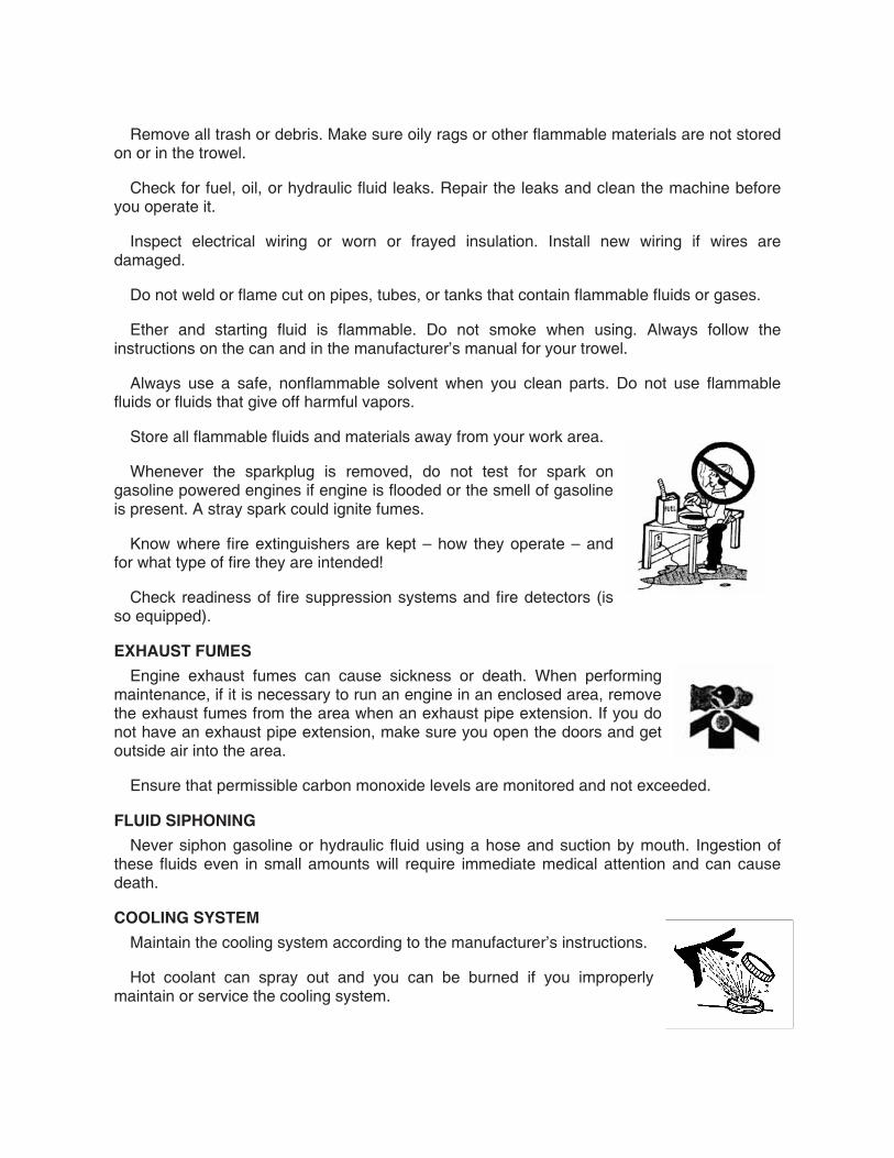
COOLING SYSTEM
Maintain the cooling system according to the manufacturer’s instructions.
Hot coolant can spray out and you can be burned if you improperly maintain or service the cooling system.

Remove filler cap only when cool.
TROWEL BLADES AND PANS
• Do not attempt to clean, service or perform adjustments on the trowel while it is running.
• Do not remove while the trowel is hanging overhead. Always support the trowel securely on a flat, level surface before changing blades or pans.
• Always handle blades and pans carefully. Worn blades or pans may develop sharp edges that can cause serious cuts.
• Always replace worn or damaged parts with service parts designated by the manufacturer.
• Replace blades and pans as a complete set – even if only one blade or pan is showing wear or damage. They can wear differently depending on different jobs, and a difference in blade size will damage the finish of the slab surface.
HYDRAULIC SYSTEMS
Hydraulic fluid systems operate under high pressure. Even a small leak can have enough force to penetrate the eyes or skin. If injury occurs, seek immediate medical treatment by a physician familiar with injuries that are caused by hydraulic oil escaping under pressure.
Use a piece of wood or cardboard to find hydraulic oil leaks. Do not use your bare hands.
Wear safety glasses to prevent injuries to the eyes.
A FINAL WORD TO THE USER
Remember that YOU are the key to safety. Good safety practices not only protect you but protect the people around you.
You have read this safety manual and the manufacturer’s manual(s) for your specific trowel. Make them a working part of your safety program. Keep in mind that this safety manual is written for only this type of machine.
Practice all other usual and customary safe working precautions, and above all –
REMEMBER – SAFETY IS UP TO YOU
YOU CAN PREVENT SERIOUS
INJURY OR DEATH