pe ove eteet sltis - analog.com analog.com 3 advanced power management software and hardware analog...
TRANSCRIPT
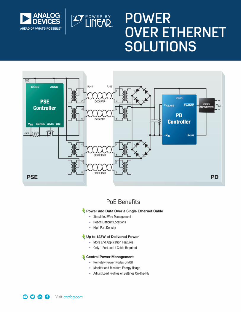
POWER OVER ETHERNET SOLUTIONS
Visit analog.com
Power and Data Over a Single Ethernet Cable
• Simplified Wire Management
• Reach Difficult Locations
• High Port Density
Up to 123W of Delivered Power
• More End Application Features
• Only 1 Port and 1 Cable Required
Central Power Management
• Remotely Power Nodes On/Off
• Monitor and Measure Energy Usage
• Adjust Load Profiles or Settings On-the-Fly
PoE Benefits
–
DATA PAIR
DATA PAIR
0.25Ω–55V
RJ45
1
2
1
2
3
6
3
6
RJ45
DC/DCCONVERTER
+VOUT
GND
SPARE PAIR
SPARE PAIR
4
5
4
5
7
8
7
8
PD
DGND AGND
VEE GATESENSE OUT
PSEController
GND
PWRGD
–VIN
RCLASS
PDController
–VOUT
PSE
2 Visit analog.com 3
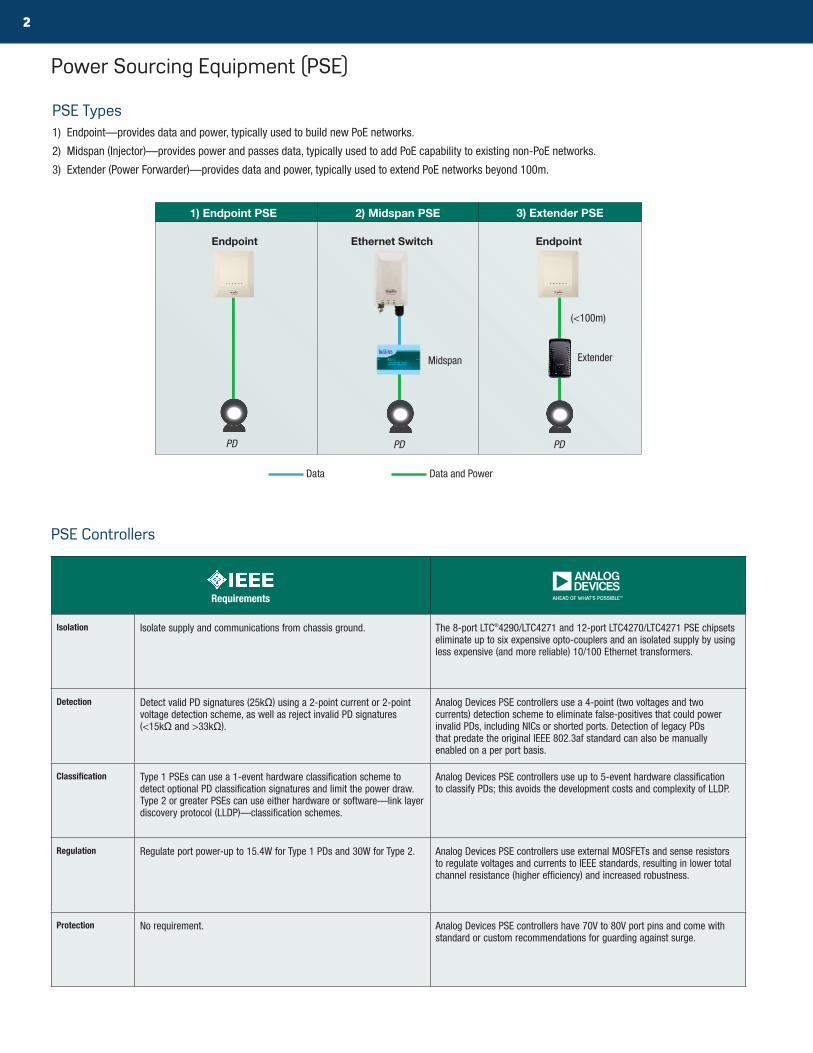
Power Sourcing Equipment (PSE)
PSE Types1) Endpoint—provides data and power, typically used to build new PoE networks.
2) Midspan (Injector)—provides power and passes data, typically used to add PoE capability to existing non-PoE networks.
3) Extender (Power Forwarder)—provides data and power, typically used to extend PoE networks beyond 100m.
PSE Controllers
Requirements
Isolation Isolate supply and communications from chassis ground. The 8-port LTC®4290/LTC4271 and 12-port LTC4270/LTC4271 PSE chipsets eliminate up to six expensive opto-couplers and an isolated supply by using less expensive (and more reliable) 10/100 Ethernet transformers.
Detection Detect valid PD signatures (25kΩ) using a 2-point current or 2-point voltage detection scheme, as well as reject invalid PD signatures (<15kΩ and >33kΩ).
Analog Devices PSE controllers use a 4-point (two voltages and two currents) detection scheme to eliminate false-positives that could power invalid PDs, including NICs or shorted ports. Detection of legacy PDs that predate the original IEEE 802.3af standard can also be manually enabled on a per port basis.
Classification Type 1 PSEs can use a 1-event hardware classification scheme to detect optional PD classification signatures and limit the power draw. Type 2 or greater PSEs can use either hardware or software—link layer discovery protocol (LLDP)—classification schemes.
Analog Devices PSE controllers use up to 5-event hardware classification to classify PDs; this avoids the development costs and complexity of LLDP.
Regulation Regulate port power-up to 15.4W for Type 1 PDs and 30W for Type 2. Analog Devices PSE controllers use external MOSFETs and sense resistors to regulate voltages and currents to IEEE standards, resulting in lower total channel resistance (higher efficiency) and increased robustness.
Protection No requirement. Analog Devices PSE controllers have 70V to 80V port pins and come with standard or custom recommendations for guarding against surge.
Endpoint Endpoint
Extender
Ethernet Switch
1) Endpoint PSE 2) Midspan PSE 3) Extender PSE
PDPD PD
Data Data and Power
Midspan
(<100m)

Visit analog.com 3
Advanced Power Management Software and HardwareAnalog Devices PSEs support a variety of operating modes and include per-port current monitoring, supply monitoring, one second current averaging and field-upgradeable firmware. Analog Devices provides C libraries for customer systems at mul-tiple levels, from control of basic PSE operation to management of overallocated and prioritized PoE switch systems.
Mode Auto Pin Detect/Class Power-Up
Automatic ICUT/ILIM
Assignment
AUTO 1 Enabled at Reset Automatically Yes
Semi-auto 0 Host Enabled Upon Request No
Manual 0 Once Upon Request Upon Request No
Shutdown 0 Disabled Disabled No
PSE Example: Isolated 12-Port PSE Chipset
Extended Power Analog Devices PSE and PD controllers provide up to 90W of power at the PD’s RJ45 input, while ensuring backward compat-ibility and interoperability with Type 1 and 2 equipment. Type 3 and 4 equipment and LTPoE++ controllers operate exclusively.
DEVICE PSE
STANDARD 802.3at LTPoE++
TYPE TYPE 1 TYPE 2 38.7W 52.7W 70W 90W
PD
802.
3at TYPE 1 13W 13W 13W 13W 13W 13W
TYPE 2 13W 25.5W 25.5W 25.5W 25.5W 25.5W
LTPo
E++
38.7W 13W 25.5W 38.7W 38.7W 38.7W 38.7W
52.7W 13W 25.5W – 52.7W 52.7W 52.7W
70W 13W 25.5W – – 70W 70W
90W 13W 25.5W – – – 90W
LTC4271 LTC4270
GP0
GP1
MID
RESET
MSD
AUTO
SCL
AD0AD1AD2AD3AD6 DGND CAP1
SDAINSDAOUT
VDD33
SENSE1
GATE1
OUT1
XIO0 XIO1
SENSEn
GATEn
OUTn
CAP2 VEEAGND VSSK
INT
••3.3V
3.3V
–54V
••3.3V –54V
100V
S1B
S1B
–54V
–54V
S1B
S1B
PORTn
PORT1
0.25Ω
0.25Ω
–54V
Robust Surge Protection
Low Cost Isolation Efficient Regulation
EffectiveDetection and SimpleClassification
No IsolationRequired onI2C Interface
DEVICE PSE
STANDARD 802.3bt
TYPE TYPE 1 TYPE 2 TYPE 3 TYPE 4
PD
802.
3bt
TYPE 1 13W 13W 13W 13W
TYPE 2 13W 25.5W 25.5W 25.5W
TYPE 3 13W 25.5W 40W, 51W 40W, 51W
TYPE 4 13W 25.5W 40W, 51W 62W, 71.3W

4 Visit analog.com 5
Cabling and Magnetics
PSE Controller Selection
Low EMIAnalog Devices PSEs use preventative techniques to minimize electromagnetic interference (EMI). For example, the blue line in the graph shows the GTEM radiated emissions scan for the 12-port LTC4270/LTC4271 demo board (DC1840), which is safely below the CISPR 22 Class B limit, rep-resented by the red line, with some appreciable margin to spare.
StandardPD Input Power
# of Cables Required
Pairs Used (Out of 4)
Cable Bundle Size
Rec Cable Type
Max Cable Current Magnetics
PoE (IEEE 802.3af) 13W
1
2
100
CAT-5350mA
StandardPoE+ (IEEE 802.3at) 25.5W 600mA
PoE++ (IEEE 802.3bt)
40W
4 CAT-5e
900mA
High Power
51W 1.2A
62W80
1.45A
71W 1.72A
Analog Devices LTPoE++
38.7W100
777mA
52.7W 1.1A
70W 80 1.5A
90W 25 2.2A
FREQUENCY (MHz)
0–20
RADI
ATED
EM
ISSI
ONS
(dBµ
V/m
)
–10
0
10
20
300 400
40
100 200 700 800 900500 600 1000
30
GTEM CELL MEASUREMENTCORRECTED PER IEC 61000-4-20DETECTOR = PEAK HOLDRBW = 120kHzVBW = 300kHzSWEEP TIME = 680ms# OF POINTS = 8084
DC1840
CISPR 22 CLASS B LIMIT
NOISE FLOOR
Part NumberNumber of Ports
Internal Isolation
StandardPD Input Power
Packages (mm) Demo BoardsLTPoE++ PoE++ PoE+ PoE
LTC4270A/LTC4271 12 • • • • 90W 7 × 8 QFN-52 / 4 × 4 QFN-24 DC1679 + SB002
LTC4270B/LTC4271 12 • • • 25.5W 7 × 8 QFN-52 / 4 × 4 QFN-24 DC1840
LTC4270C/LTC4271 12 • • 13W 7 × 8 QFN-52 / 4 × 4 QFN-24 DC1680 + SB021
LTC4290A/LTC4271 8 • • • • 90W 6 × 6 QFN-40 / 4 × 4 QFN-24 DC1679 + SB073
LTC4290B/LTC4271 8 • • • 25.5W 6 × 6 QFN-40 / 4 × 4 QFN-24 DC1843
LTC4290C/LTC4271 8 • • 13W 6 × 6 QFN-40 / 4 × 4 QFN-24 DC1680 + SB090
LTC4291/LTC4292 4 • • • • 71.3W 6 × 6 QFN-40 / 4 × 4 QFN-24 DC2685
LTC4266A 4 • • • 90W 5 × 7 QFN-38 DC1815
LTC4266 4 • • 25.5W 5 × 7 QFN-38, SSOP-36 DC1366
LTC4266C 4 • 13W 5 × 7 QFN-38
LTC4279 1 • • • 123W 4 × 5 QFN-20, SO-16 DC2541, DC2579
LTC4274A 1 • • • 90W 5 × 7 QFN-38 DC1814
LTC4274 1 • • 25.5W 5 × 7 QFN-38 DC1567
LTC4274C 1 • 13W 5 × 7 QFN-38
LTC4263 1 • 13W 4 × 3 DFN-14, SO-14 DC981A/B
Visit analog.com 5
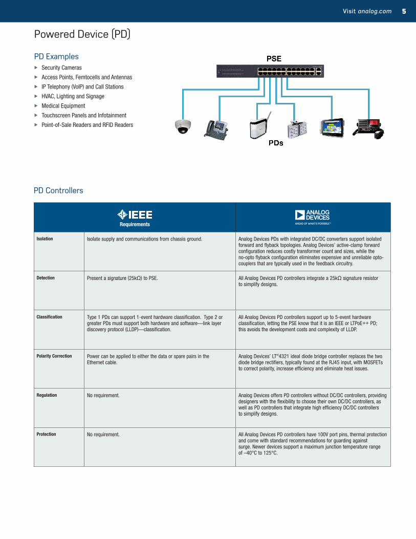
Powered Device (PD)
PD Examples X Security Cameras
X Access Points, Femtocells and Antennas
X IP Telephony (VoIP) and Call Stations
X HVAC, Lighting and Signage
X Medical Equipment
X Touchscreen Panels and Infotainment
X Point-of-Sale Readers and RFID Readers
Requirements
Isolation Isolate supply and communications from chassis ground. Analog Devices PDs with integrated DC/DC converters support isolated forward and flyback topologies. Analog Devices’ active-clamp forward configuration reduces costly transformer count and sizes, while the no-opto flyback configuration eliminates expensive and unreliable opto-couplers that are typically used in the feedback circuitry.
Detection Present a signature (25kΩ) to PSE. All Analog Devices PD controllers integrate a 25kΩ signature resistor to simplify designs.
Classification Type 1 PDs can support 1-event hardware classification. Type 2 or greater PDs must support both hardware and software—link layer discovery protocol (LLDP)—classification.
All Analog Devices PD controllers support up to 5-event hardware classification, letting the PSE know that it is an IEEE or LTPoE++ PD; this avoids the development costs and complexity of LLDP.
Polarity Correction Power can be applied to either the data or spare pairs in the Ethernet cable.
Analog Devices’ LT®4321 ideal diode bridge controller replaces the two diode bridge rectifiers, typically found at the RJ45 input, with MOSFETs to correct polarity, increase efficiency and eliminate heat issues.
Regulation No requirement. Analog Devices offers PD controllers without DC/DC controllers, providing designers with the flexibility to choose their own DC/DC controllers, as well as PD controllers that integrate high efficiency DC/DC controllers to simplify designs.
Protection No requirement. All Analog Devices PD controllers have 100V port pins, thermal protection and come with standard recommendations for guarding against surge. Newer devices support a maximum junction temperature range of –40°C to 125°C.
PD Controllers

6 Visit analog.com 7
Very EfficientUsing low resistance components, including low RDS(ON) MOSFETs controlled by the LT4321 ideal diode bridge controller, Analog Devices PDs provide up to 94% efficiency from the RJ45 input to the load, for simplified thermal designs and more power to the load. The load is able to har-ness more energy, and designs more easily stay within power budgets.
Extremely Low Heat Analog Devices PD solutions generate much less heat while delivering much more power than alternatives. Analog Devices’ latest generation of PD controllers utilize external MOSFETs and sense resistors to enable users to choose low resistance components in order to minimize heat dissipation, while increasing efficiency and reli-ability. Similarly, the LT4320 and LT4321 diode bridge controllers replace diodes with MOSFETs to lower channel resistance and improve thermal performance.
CURRENT (mA)
0
POW
ER D
ISSI
PATI
ON (W
)
0
0.8
1.0
1.2
1.8
1.4
600
0.6
0.4
0.2
1.6
200 400 800 1000
POWERSAVED
IN12 = 55VIN36 = 0VIN45 = FLOATIN78 = FLOAT
LT4321 (50mΩ FETs)DIODES (S2B)
Simple Topology All Analog Devices PD controllers use a single-signature PD topology to simplify designs and reduce costs. IEEE 802.3bt also introduced the dual-signature PD topology, which is a complex and costly implementation that calls for two PD controllers, two detection resistors and two classification results to support two independent PD loads. Both single and dual PD topologies can support two loads.
Single-Signature PD Dual-Signature PD
RJ45
1
2
6
4
3
5
7
8
1000BASE-T
TX1
TX2
TX3
TX4
PD
+
–VOUT
RJ45
1
2
6
4
3
5
7
8
1000BASE-T
TX1
TX2
TX3
TX4
PD1
+
–VOUT1
PD2
+
–VOUT2

Visit analog.com 7
PD Controller Selection
PD Example: High Efficiency PoE++ PD Solution with 12VDC and 24VAC Auxiliary Input
LT4320AUX INPUTDC TO 600Hz
DATAPAIRS
1
2
3
6
4
+
–
VOUT
5
8
7SPAREPAIRS
LT4321
FORWARD ORFLYBACK
DISCRETES
LT4295
PoE Diode Bridge Controller■ Maximizes Power Efficiency■ Reduces Heat, Eliminates Thermal
Design Problems■ Less Than 800µA Quiescent
Operating Current■ Fully Compatible with IEEE 802.3
Detection and Classification
PD Forward/Flyback Controller■ IEEE 802.3bt Draft 2.1 Compliant■ High Efficiency Forward or No-Opto
Flyback Operation■ Superior Surge Protection (100V)■ Wide Junction Temperature Range
(–40°C to125°C)
Ideal Diode Bridge Controller■ Maximizes Power Efficiency■ Reduces Heat, Eliminates Thermal
Design Problems■ DC to 600Hz■ 9V to 72V Operating Voltage Range■ IQ = 1.5mA (Typical)
*All Analog Devices PD Controllers integrate a signature resistor.
Part Number Standard
PD Input Power Integrated DC/DC
ControllerDC/DC
Topology
Integrated Hot Swap MOSFET
Temp Range
Package Dimensions (mm)90W 71W 25.5W 13W
LTC4257 PoE • • C, I 3 × 3 DFN-8, SO-8
LTC4267 PoE • • Flyback • C, I 5 × 3 DFN-16, SO-16
LTC4265 PoE+ • • • C, I 4 × 3 DFN-12
LTC4269-1 PoE+ • • • Flyback • C, I 7 × 4 DFN-32
LTC4269-2 PoE+ • • • Forward • C, I 7 × 4 DFN-32
LTC4278 PoE+ • • • Flyback • C, I 7 × 4 DFN-32
LT4275A LTPoE++ • • • I, H 3 × 3 DFN-10, MSOP-10
LT4275B PoE+ • • I, H 3 × 3 DFN-10, MSOP-10
LT4275C PoE • I, H 3 × 3 DFN-10, MSOP-10
LT4276A LTPoE++ • • • • Forward, Flyback I, H 4 × 5 QFN-28
LT4276B PoE+ • • • Forward, Flyback I, H 4 × 5 QFN-28
LT4276C PoE • • Forward, Flyback I, H 4 × 5 QFN-28
LT4294 PoE++ • • • I, H 3 × 3 DFN-10, MSOP-10
LT4295 PoE++ • • • • Forward, Flyback I, H 4 × 5 QFN-28

Analog Devices, Inc. Worldwide Headquarters
Analog Devices, Inc. One Technology Way P.O. Box 9106 Norwood, MA 02062-9106 U.S.A. Tel: 781.329.4700 (800.262.5643, U.S.A. only) Fax: 781.461.3113
Analog Devices, Inc. Europe Headquarters
Analog Devices GmbH Otl-Aicher-Str. 60-6480807 München Germany Tel: 49.89.76903.0 Fax: 49.89.76903.157
Analog Devices, Inc. Japan Headquarters
Analog Devices, KK New Pier Takeshiba South Tower Building 1-16-1 Kaigan, Minato-ku, Tokyo, 105-6891 Japan Tel: 813.5402.8200 Fax: 813.5402.1064
Analog Devices, Inc. Asia Pacific Headquarters
Analog Devices 5F, Sandhill Plaza 2290 Zuchongzhi Road Zhangjiang Hi-Tech Park Pudong New District Shanghai, China 201203 Tel: 86.21.2320.8000 Fax: 86.21.2320.8222
©2016 Analog Devices, Inc. All rights reserved. Trademarks and registered trademarks are the property of their respective owners.Ahead of What’s Possible is a trademark of Analog Devices.BRPoES-3/18(C)
analog.com
PD Demo Boards X Complete ready to copy-and-paste reference designs, including
schematics, BOMs and layout files
X Simultaneously evaluate PD controllers and ideal diode bridges
X Magnetics sized and specified for exact load voltages and currents
X Compatible with existing Analog Devices PSE demo boards
IC Part Number Standard PD Input PowerOutput (V/I)
Input Voltage
Input-to-Output Efficiency
Demo Board Part Number
LTC4267 PoE 3.84W 3.3V/1A 38V to 57V 75.0% DC804B-A
LTC4267 PoE 13W 3.3V/2.6A 37V to 57V 78.0% DC917A
LTC4267 PoE 13W 12V/0.9A 37V to 57V 85.0% DC1145B
LTC4267 PoE 13W 1.8V/2.5A, 2.5V/1.5A, 3.3V/0.5A
37V to 57V 76.0% DC859A
LTC4265 PoE+ 25.5W – 37V to 57V – DC1415
LTC4269-1 PoE+ 25.5W 3.3V/6.6A 37V to 57V 89.0% DC1335A-A
LTC4269-1 PoE+ 25.5W 5V/4.5A 37V to 57V 91.0% DC1335B-B
LTC4269-1 PoE+ 25.5W 12V/2A 37V to 57V 90.8% DC1335B-C
LTC4269-2 PoE+ 25.5W 5V/4.6A 37V to 57V 92.5% DC1351B
LTC4278 PoE+ 25.5W 5V/4.5A 9V to 57V 89.0% DC1561
LT4275C/LT4321 PoE 13W – 37V to 57V – DC2093A-C
LT4275B/LT4321 PoE+ 25.5W – 37V to 57V – DC2093A-B
LT4275A/LT4321 LTPoE++ 90W – 37V to 57V – DC2093A-A
LT4275A/LT4321/LTM®8027 LTPoE++ 38.7W 12V/3A 37V to 57V 90.0% DC2125A
LT4276C/LT4321 PoE 13W 5V/2.3A 37V to 57V 90.0% DC2046A-F
LT4276B/LT4321 PoE+ 25.5W 3.3V/6.8A 37V to 57V 90.0% DC2046A-A
LT4276B/LT4321 PoE+ 25.5W 5V/4.7A 37V to 57V 92.0% DC2046A-B
LT4276B/LT4321 PoE+ 25.5W 12V/1.9A 37V to 57V 92.0% DC2046A-C
LT4276B/LT4321 PoE+ 25.5W 24V/1A 37V to 57V 92.0% DC2046A-D
LT4276A/LT4321 LTPoE++ 38.7W 5V/7A 37V to 57V 92.0% DC2046A-E
LT4276A/LT4321 LTPoE++ 70W 5V/13A 37V to 57V 92.5% DC2262A-A
LT4276A/LT4321 LTPoE++ 90W 12V/7A 37V to 57V 93.5% DC2262A-B
LT4276B/LT4321/LT4320 PoE+ 25.5W 12V/1.9A 9V to 57V 92.0% DC2047A-A
LT4295/LT4321 PoE++ 40W 12V/3A 37V to 57V 92.0% DC2475A-A
LT4295/LT4321 PoE++ 51W 12V/3.9A 37V to 57V 91.5% DC2539A-A
LT4295/LT4321 PoE++ 62W 24V/2.3A 37V to 57V 92.0% DC2476A-A
LT4295/LT4321 PoE++ 71W 24V/2.7A 37V to 57V 92.0% DC2476A-A
LT4295/LT4321 PoE++ 71W 12V/5.5V 37V to 57V 93.0% DC2584A-A
LT4294/LT4321 PoE++ 71W – 37V to 57V 99.0% DC2583A