pella installation instructions block frame hinged...
TRANSCRIPT
BFHD – 1 Revised 01/17/2018 © 2018 Pella CorporationBFHD – 1 (ED)
THE FOLLOWING INSTALLATION METHODS ARE INCLUDED IN THIS BOOKLET:
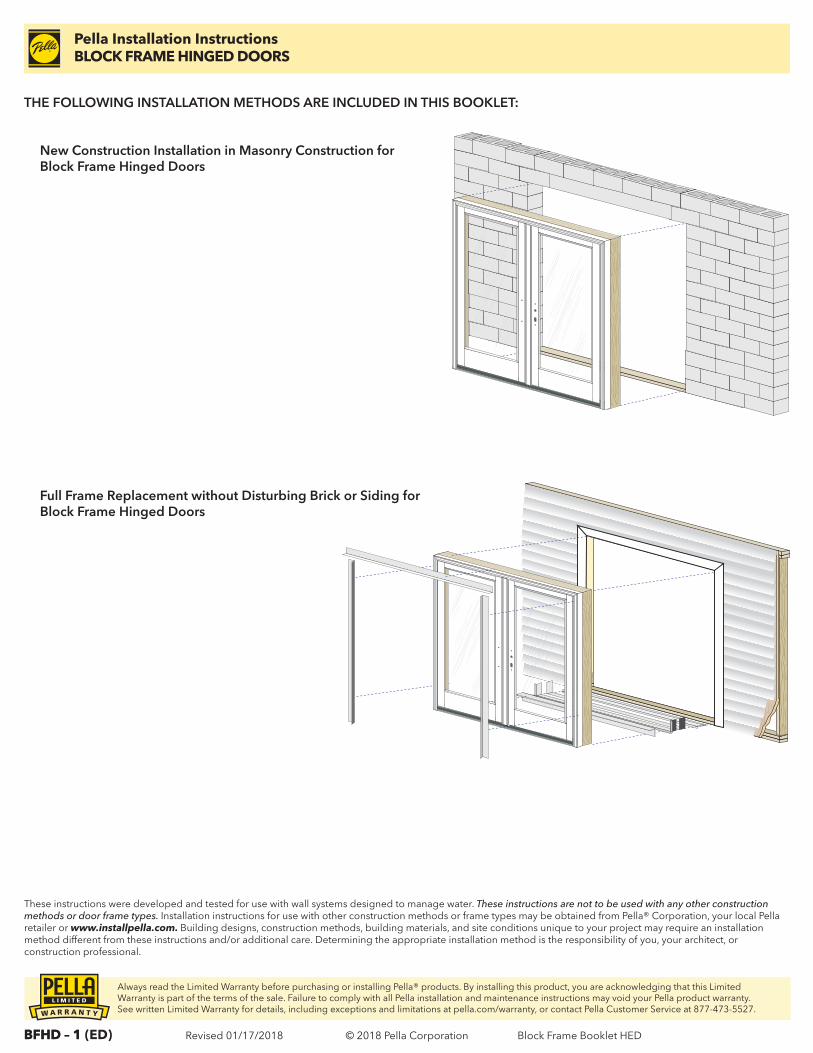
New Construction Installation in Masonry Construction for Block Frame Hinged Doors
These instructions were developed and tested for use with wall systems designed to manage water. These instructions are not to be used with any other construction methods or door frame types. Installation instructions for use with other construction methods or frame types may be obtained from Pella® Corporation, your local Pella retailer or www.installpella.com. Building designs, construction methods, building materials, and site conditions unique to your project may require an installation method different from these instructions and/or additional care. Determining the appropriate installation method is the responsibility of you, your architect, or construction professional.
Full Frame Replacement without Disturbing Brick or Siding for Block Frame Hinged Doors
Pella Installation InstructionsBLOCK FRAME HINGED DOORS
Always read the Limited Warranty before purchasing or installing Pella® products. By installing this product, you are acknowledging that this Limited Warranty is part of the terms of the sale. Failure to comply with all Pella installation and maintenance instructions may void your Pella product warranty. See written Limited Warranty for details, including exceptions and limitations at pella.com/warranty, or contact Pella Customer Service at 877-473-5527.
Block Frame Booklet HED
BFHD – 2 Revised 01/17/2018 © 2018 Pella Corporation
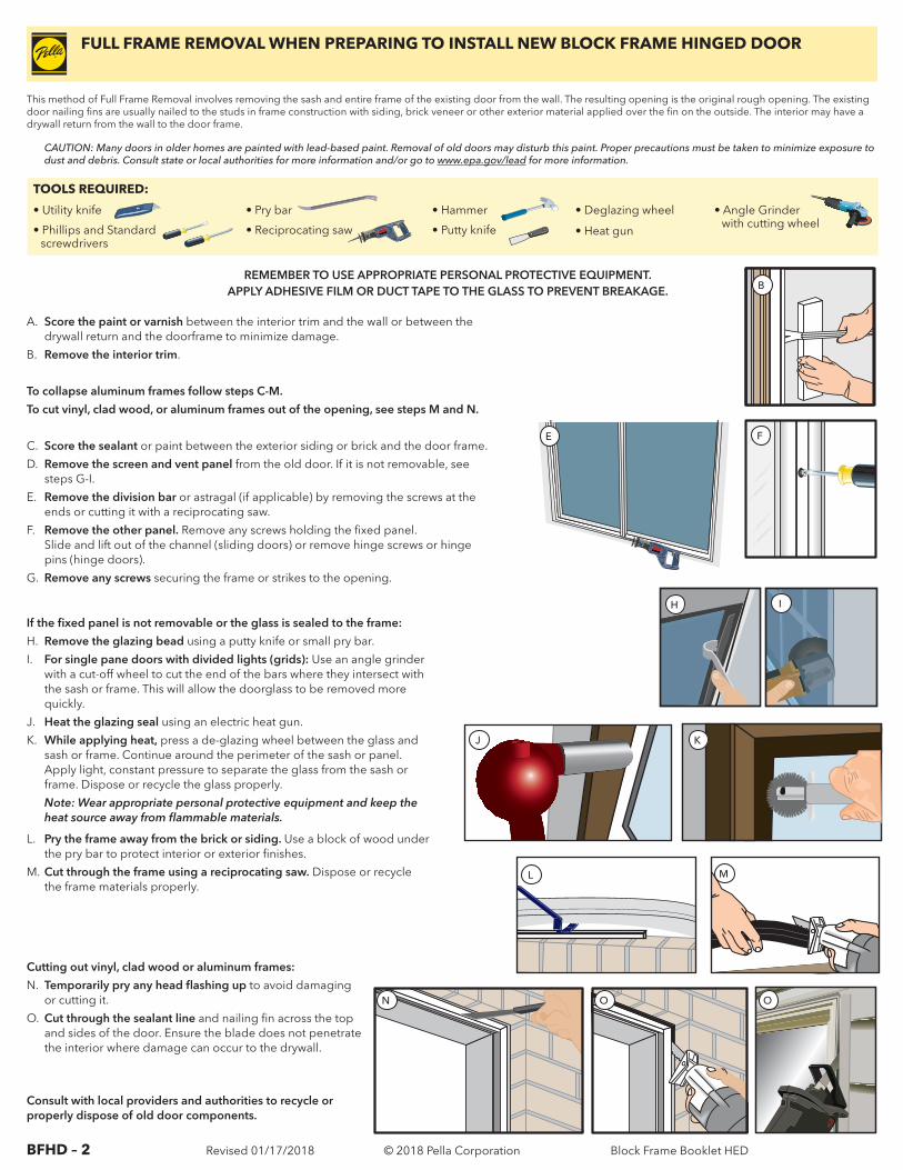
If the fixed panel is not removable or the glass is sealed to the frame:
H. Remove the glazing bead using a putty knife or small pry bar.
I. For single pane doors with divided lights (grids): Use an angle grinder with a cut-off wheel to cut the end of the bars where they intersect with the sash or frame. This will allow the doorglass to be removed more quickly.
J. Heat the glazing seal using an electric heat gun.
K. While applying heat, press a de-glazing wheel between the glass and sash or frame. Continue around the perimeter of the sash or panel. Apply light, constant pressure to separate the glass from the sash or frame. Dispose or recycle the glass properly.
Note: Wear appropriate personal protective equipment and keep the heat source away from flammable materials.
L. Pry the frame away from the brick or siding. Use a block of wood under the pry bar to protect interior or exterior finishes.
M. Cut through the frame using a reciprocating saw. Dispose or recycle the frame materials properly.
This method of Full Frame Removal involves removing the sash and entire frame of the existing door from the wall. The resulting opening is the original rough opening. The existing door nailing fins are usually nailed to the studs in frame construction with siding, brick veneer or other exterior material applied over the fin on the outside. The interior may have a drywall return from the wall to the door frame.
TOOLS REQUIRED:
• Utility knife
• Phillips and Standard screwdrivers
• Pry bar
• Reciprocating saw
• Hammer
• Putty knife
• Deglazing wheel
• Heat gun
• Angle Grinder with cutting wheel
REMEMBER TO USE APPROPRIATE PERSONAL PROTECTIVE EQUIPMENT.APPLY ADHESIVE FILM OR DUCT TAPE TO THE GLASS TO PREVENT BREAKAGE.
CAUTION: Many doors in older homes are painted with lead-based paint. Removal of old doors may disturb this paint. Proper precautions must be taken to minimize exposure to dust and debris. Consult state or local authorities for more information and/or go to www.epa.gov/lead for more information.
A. Score the paint or varnish between the interior trim and the wall or between the drywall return and the doorframe to minimize damage.
B. Remove the interior trim.
To collapse aluminum frames follow steps C-M.
To cut vinyl, clad wood, or aluminum frames out of the opening, see steps M and N.
C. Score the sealant or paint between the exterior siding or brick and the door frame.
D. Remove the screen and vent panel from the old door. If it is not removable, see steps G-I.
E. Remove the division bar or astragal (if applicable) by removing the screws at the ends or cutting it with a reciprocating saw.
F. Remove the other panel. Remove any screws holding the fixed panel. Slide and lift out of the channel (sliding doors) or remove hinge screws or hinge pins (hinge doors).
G. Remove any screws securing the frame or strikes to the opening.
Cutting out vinyl, clad wood or aluminum frames:
N. Temporarily pry any head flashing up to avoid damaging or cutting it.
O. Cut through the sealant line and nailing fin across the top and sides of the door. Ensure the blade does not penetrate the interior where damage can occur to the drywall.
IH
E
J K
L M
N O O
FULL FRAME REMOVAL WHEN PREPARING TO INSTALL NEW BLOCK FRAME HINGED DOOR
F
B
Consult with local providers and authorities to recycle or properly dispose of old door components.
Block Frame Booklet HED
BFHD – 3 Revised 01/17/2018 © 2018 Pella Corporation
PREPARING FOR BLOCK FRAME HINGED DOOR INSTALLATION
These instructions were developed and tested for use with wall systems designed to manage water. These instructions are not to be used with any other construction methods or doorframe types. Installation instructions for use with other construction methods or frame types may be obtained from Pella® Corporation, your local Pella retailer or www.installpella.com. Building designs, construction methods, building materials, and site conditions unique to your project may require an installation method different from these instructions and/or additional care. Determining the appropriate installation method is the responsibility of you, your architect, or construction professional.
Always read the Limited Warranty before purchasing or installing Pella® products. By installing this product, you are acknowledging that this Limited Warranty is part of the terms of the sale. Failure to comply with all Pella installation and maintenance instructions may void your Pella product warranty. See written Limited Warranty for details, including exceptions and limitations at pella.com/warranty, or contact Pella Customer Service at 877-473-5527.
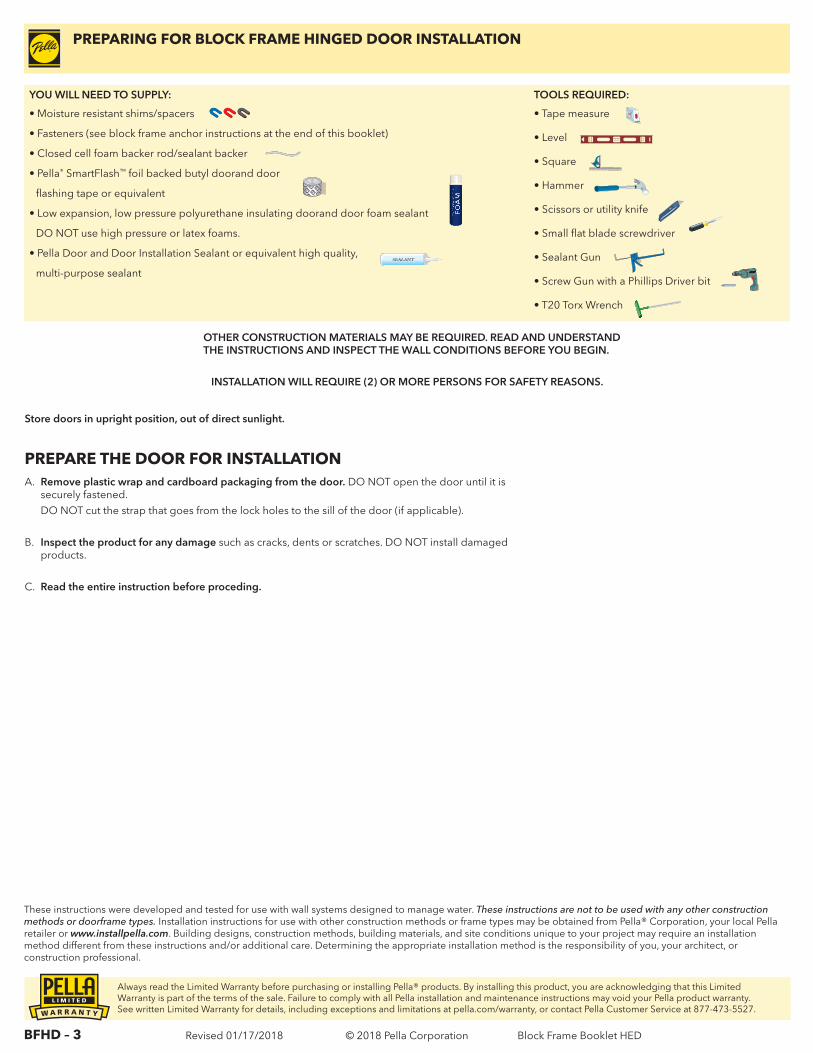
YOU WILL NEED TO SUPPLY: TOOLS REQUIRED:
• Moisture resistant shims/spacers
• Fasteners (see block frame anchor instructions at the end of this booklet)
• Closed cell foam backer rod/sealant backer
• Pella® SmartFlash™ foil backed butyl doorand door
flashing tape or equivalent
• Low expansion, low pressure polyurethane insulating doorand door foam sealant
DO NOT use high pressure or latex foams.
• Pella Door and Door Installation Sealant or equivalent high quality,
multi-purpose sealant
• Tape measure
• Level
• Square
• Hammer
• Scissors or utility knife
• Small flat blade screwdriver
• Sealant Gun
• Screw Gun with a Phillips Driver bit
• T20 Torx Wrench
SEALANTSEALANT
INSTALLATION WILL REQUIRE (2) OR MORE PERSONS FOR SAFETY REASONS.
OTHER CONSTRUCTION MATERIALS MAY BE REQUIRED. READ AND UNDERSTAND THE INSTRUCTIONS AND INSPECT THE WALL CONDITIONS BEFORE YOU BEGIN.
Store doors in upright position, out of direct sunlight.
A. Remove plastic wrap and cardboard packaging from the door. DO NOT open the door until it is securely fastened.
DO NOT cut the strap that goes from the lock holes to the sill of the door (if applicable).
B. Inspect the product for any damage such as cracks, dents or scratches. DO NOT install damaged products.
C. Read the entire instruction before proceding.
PREPARE THE DOOR FOR INSTALLATION
Block Frame Booklet HED
BFHD – 4 Revised 01/17/2018 © 2018 Pella Corporation
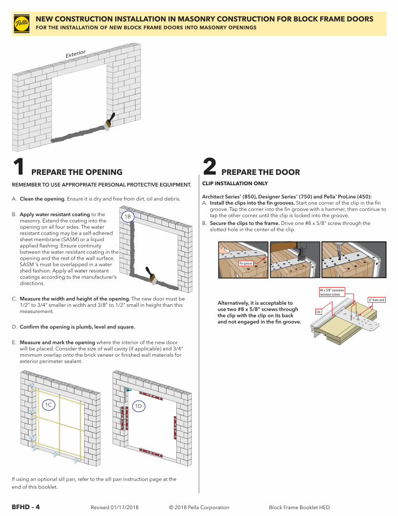
1 PREPARE THE OPENINGREMEMBER TO USE APPROPRIATE PERSONAL PROTECTIVE EQUIPMENT.
A. Clean the opening. Ensure it is dry and free from dirt, oil and debris.
B. Apply water resistant coating to the masonry. Extend the coating into the opening on all four sides. The water resistant coating may be a self-adhered sheet membrane (SASM) or a liquid applied flashing. Ensure continuity between the water resistant coating in the opening and the rest of the wall surface. SASM ’s must be overlapped in a water shed fashion. Apply all water resistant coatings according to the manufacturer’s directions.
C. Measure the width and height of the opening. The new door must be 1/2" to 3/4" smaller in width and 3/8" to 1/2" small in height than this measurement.
D. Confirm the opening is plumb, level and square.
E. Measure and mark the opening where the interior of the new door will be placed. Consider the size of wall cavity (if applicable) and 3/4" minimum overlap onto the brick veneer or finished wall materials for exterior perimeter sealant.
NEW CONSTRUCTION INSTALLATION IN MASONRY CONSTRUCTION FOR BLOCK FRAME DOORS for the installation of new block frame doors into masonry openings
6“ from end
Lip
#6 x 5/8” corrosionresistant screws
Fin groove
CLIP INSTALLATION ONLY
1B
If using an optional sill pan, refer to the sill pan instruction page at theend of this booklet.
1C 1D
2 PREPARE THE DOOR
Architect Series® (850), Designer Series® (750) and Pella® ProLine (450):A. Install the clips into the fin grooves. Start one corner of the clip in the fin
groove. Tap the corner into the fin groove with a hammer, then continue to tap the other corner until the clip is locked into the groove.
B. Secure the clips to the frame. Drive one #8 x 5/8" screw through the slotted hole in the center of the clip.
Alternatively, it is acceptable to use two #8 x 5/8" screws through the clip with the clip on its back and not engaged in the fin groove.
Interior
Exterior
Exterior
Block Frame Booklet HED
BFHD – 5 Revised 01/17/2018 © 2018 Pella Corporation
NEW CONSTRUCTION INSTALLATION IN MASONRY CONSTRUCTION FOR BLOCK FRAME DOORS for the installation of new block frame doors into masonry openings
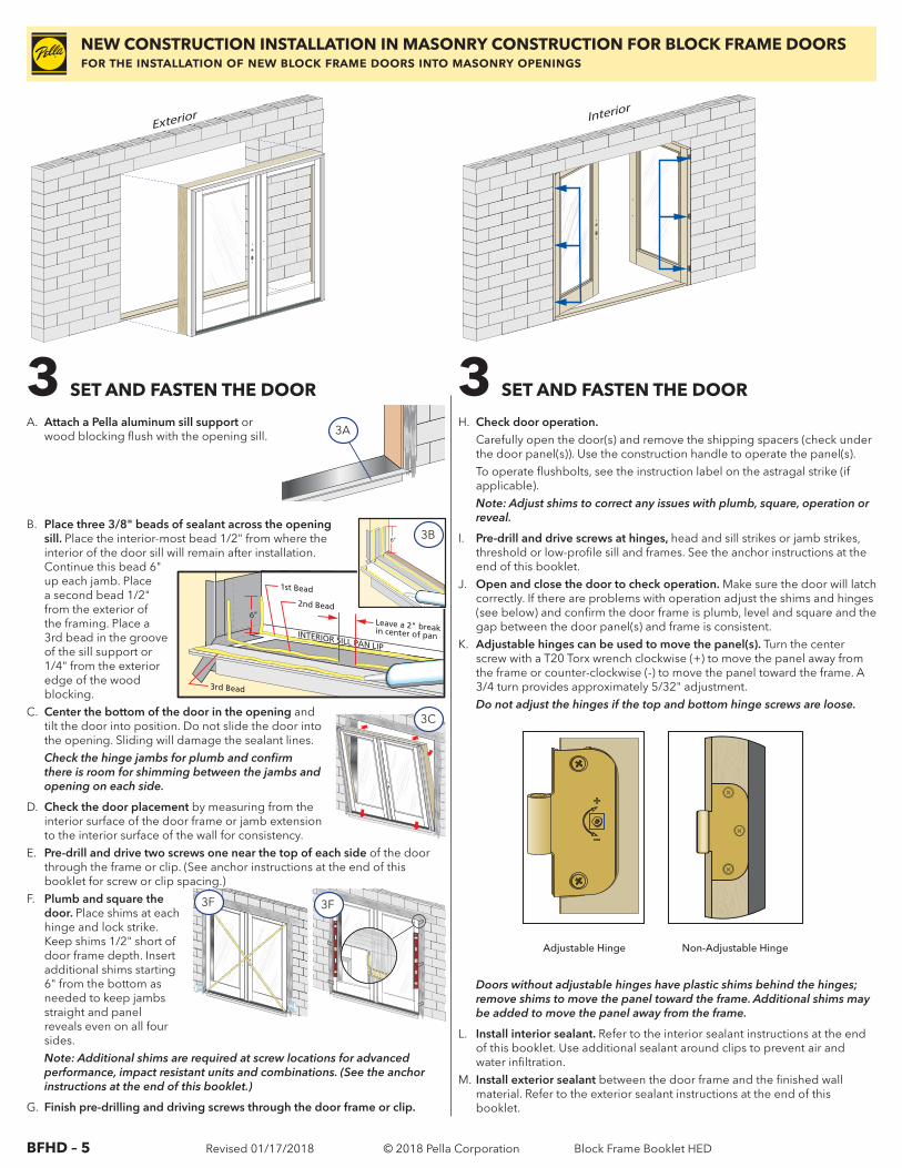
3 SET AND FASTEN THE DOOR
H. Check door operation. Carefully open the door(s) and remove the shipping spacers (check under
the door panel(s)). Use the construction handle to operate the panel(s). To operate flushbolts, see the instruction label on the astragal strike (if
applicable).Note: Adjust shims to correct any issues with plumb, square, operation or reveal.
I. Pre-drill and drive screws at hinges, head and sill strikes or jamb strikes, threshold or low-profile sill and frames. See the anchor instructions at the end of this booklet.
J. Open and close the door to check operation. Make sure the door will latch correctly. If there are problems with operation adjust the shims and hinges (see below) and confirm the door frame is plumb, level and square and the gap between the door panel(s) and frame is consistent.
K. Adjustable hinges can be used to move the panel(s). Turn the center screw with a T20 Torx wrench clockwise (+) to move the panel away from the frame or counter-clockwise (-) to move the panel toward the frame. A 3/4 turn provides approximately 5/32" adjustment.Do not adjust the hinges if the top and bottom hinge screws are loose.
Adjustable Hinge Non-Adjustable Hinge
Doors without adjustable hinges have plastic shims behind the hinges; remove shims to move the panel toward the frame. Additional shims may be added to move the panel away from the frame.
L. Install interior sealant. Refer to the interior sealant instructions at the end of this booklet. Use additional sealant around clips to prevent air and water infiltration.
M. Install exterior sealant between the door frame and the finished wall material. Refer to the exterior sealant instructions at the end of this booklet.
Interior
Exterior
Exterior
Interior
Exterior
Exterior
A. Attach a Pella aluminum sill support or wood blocking flush with the opening sill.
B. Place three 3/8" beads of sealant across the opening sill. Place the interior-most bead 1/2" from where the interior of the door sill will remain after installation. Continue this bead 6" up each jamb. Place a second bead 1/2" from the exterior of the framing. Place a 3rd bead in the groove of the sill support or 1/4" from the exterior edge of the wood blocking.
C. Center the bottom of the door in the opening and tilt the door into position. Do not slide the door into the opening. Sliding will damage the sealant lines.Check the hinge jambs for plumb and confirm there is room for shimming between the jambs and opening on each side.
D. Check the door placement by measuring from the interior surface of the door frame or jamb extension to the interior surface of the wall for consistency.
E. Pre-drill and drive two screws one near the top of each side of the door through the frame or clip. (See anchor instructions at the end of this booklet for screw or clip spacing.)
F. Plumb and square the door. Place shims at each hinge and lock strike. Keep shims 1/2" short of door frame depth. Insert additional shims starting 6" from the bottom as needed to keep jambs straight and panel reveals even on all four sides.Note: Additional shims are required at screw locations for advanced performance, impact resistant units and combinations. (See the anchor instructions at the end of this booklet.)
G. Finish pre-drilling and driving screws through the door frame or clip.
3 SET AND FASTEN THE DOOR
3A
3C
3F
12 0 3 0 4 0 5 0 6 0 7 0
23
INCHESmm
3F
EXTERIOR SILL PAN LIP
INTERIOR SILL PAN LIP
2nd Bead
Leave a 2" break in center of pan
1st Bead
3rd Bead
6”
12
3
6” 3B
Block Frame Booklet HED
BFHD – 6 Revised 01/17/2018 © 2018 Pella Corporation
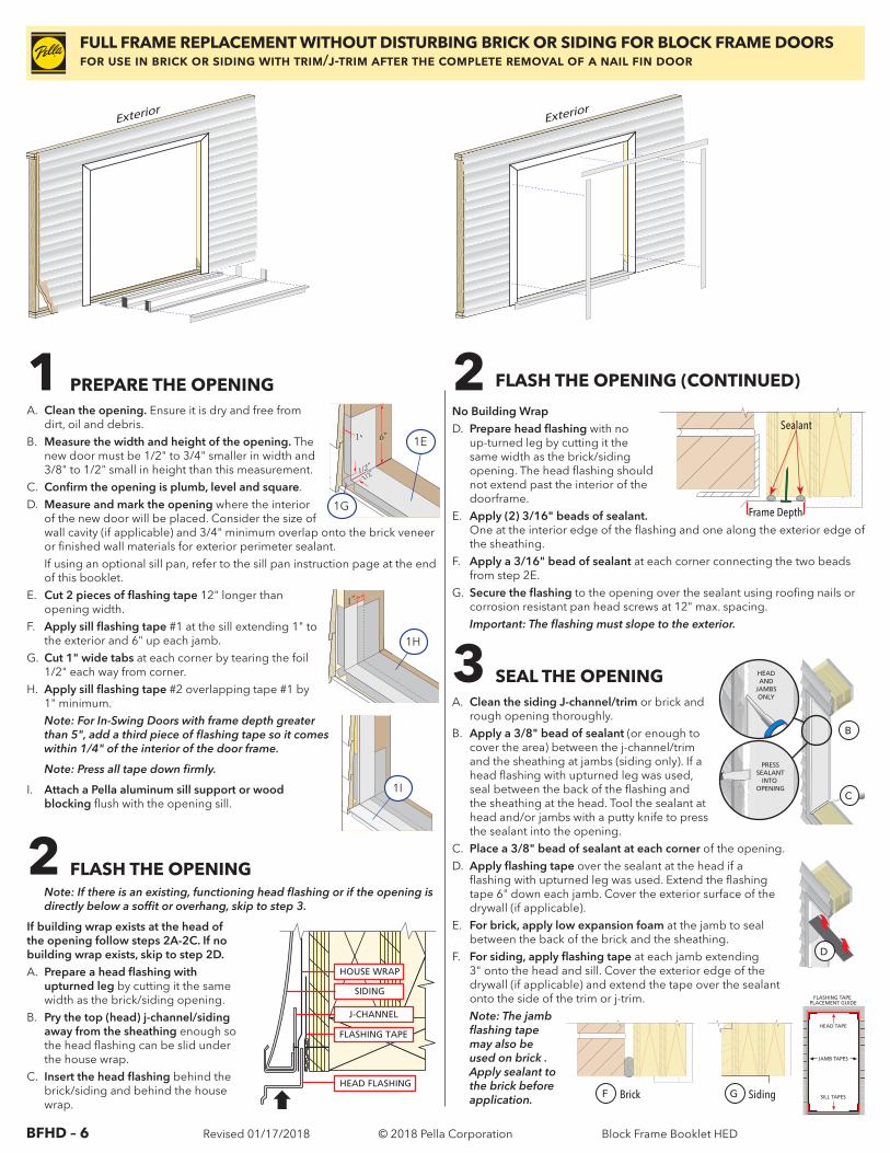
1 PREPARE THE OPENING
2 FLASH THE OPENINGNote: If there is an existing, functioning head flashing or if the opening is directly below a soffit or overhang, skip to step 3.
If building wrap exists at the head of the opening follow steps 2A-2C. If no building wrap exists, skip to step 2D.A. Prepare a head flashing with
upturned leg by cutting it the same width as the brick/siding opening.
B. Pry the top (head) j-channel/siding away from the sheathing enough so the head flashing can be slid under the house wrap.
C. Insert the head flashing behind the brick/siding and behind the house wrap.
2 FLASH THE OPENING (CONTINUED)
No Building WrapD. Prepare head flashing with no
up-turned leg by cutting it the same width as the brick/siding opening. The head flashing should not extend past the interior of the doorframe.
E. Apply (2) 3/16" beads of sealant. One at the interior edge of the flashing and one along the exterior edge of the sheathing.
F. Apply a 3/16" bead of sealant at each corner connecting the two beads from step 2E.
G. Secure the flashing to the opening over the sealant using roofing nails or corrosion resistant pan head screws at 12" max. spacing.Important: The flashing must slope to the exterior.
3 SEAL THE OPENINGA. Clean the siding J-channel/trim or brick and
rough opening thoroughly.B. Apply a 3/8" bead of sealant (or enough to
cover the area) between the j-channel/trim and the sheathing at jambs (siding only). If a head flashing with upturned leg was used, seal between the back of the flashing and the sheathing at the head. Tool the sealant at head and/or jambs with a putty knife to press the sealant into the opening.
C. Place a 3/8" bead of sealant at each corner of the opening.D. Apply flashing tape over the sealant at the head if a
flashing with upturned leg was used. Extend the flashing tape 6" down each jamb. Cover the exterior surface of the drywall (if applicable).
E. For brick, apply low expansion foam at the jamb to seal between the back of the brick and the sheathing.
F. For siding, apply flashing tape at each jamb extending 3" onto the head and sill. Cover the exterior edge of the drywall (if applicable) and extend the tape over the sealant onto the side of the trim or j-trim.Note: The jamb flashing tape may also be used on brick . Apply sealant to the brick before application.
HEAD FLASHING
HOUSE WRAP
SIDING
FLASHING TAPE
J-CHANNEL
FULL FRAME REPLACEMENT WITHOUT DISTURBING BRICK OR SIDING FOR BLOCK FRAME DOORS for use in brick or siding with trim/j-trim after the complete removal of a nail fin door
PRESSSEALANT
INTO OPENING
HEADAND
JAMBSONLY
B
C
1”
D
FLASHING TAPE PLACEMENT GUIDE
SILL TAPES
HEAD TAPE
JAMB TAPES
Brick SidingF G
A. Clean the opening. Ensure it is dry and free from dirt, oil and debris.
B. Measure the width and height of the opening. The new door must be 1/2" to 3/4" smaller in width and 3/8" to 1/2" small in height than this measurement.
C. Confirm the opening is plumb, level and square.D. Measure and mark the opening where the interior
of the new door will be placed. Consider the size of wall cavity (if applicable) and 3/4" minimum overlap onto the brick veneer or finished wall materials for exterior perimeter sealant.
If using an optional sill pan, refer to the sill pan instruction page at the end of this booklet.
E. Cut 2 pieces of flashing tape 12" longer than opening width.
F. Apply sill flashing tape #1 at the sill extending 1" to the exterior and 6" up each jamb.
G. Cut 1" wide tabs at each corner by tearing the foil 1/2" each way from corner.
H. Apply sill flashing tape #2 overlapping tape #1 by 1" minimum.Note: For In-Swing Doors with frame depth greater than 5", add a third piece of flashing tape so it comes within 1/4" of the interior of the door frame.
Note: Press all tape down firmly.
I. Attach a Pella aluminum sill support or wood blocking flush with the opening sill.
Interior
Exterior
Exterior
Exterior
Interior
Exterior
Exterior
Exterior
1I
1"
1/2"1/2"
6"
1"
1E
1G1"
1/2"1/2"
6"
1"
1H
Frame Depth
Sealant
Block Frame Booklet HED
BFHD – 7 Revised 01/17/2018 © 2018 Pella Corporation
FULL FRAME REPLACEMENT WITHOUT DISTURBING BRICK OR SIDING FOR BLOCK FRAME DOORS for use in brick or siding with trim/j-trim after the complete removal of a nail fin door
Interior
Exterior
Exterior
Exterior
Interior
Exterior
Exterior
Exterior
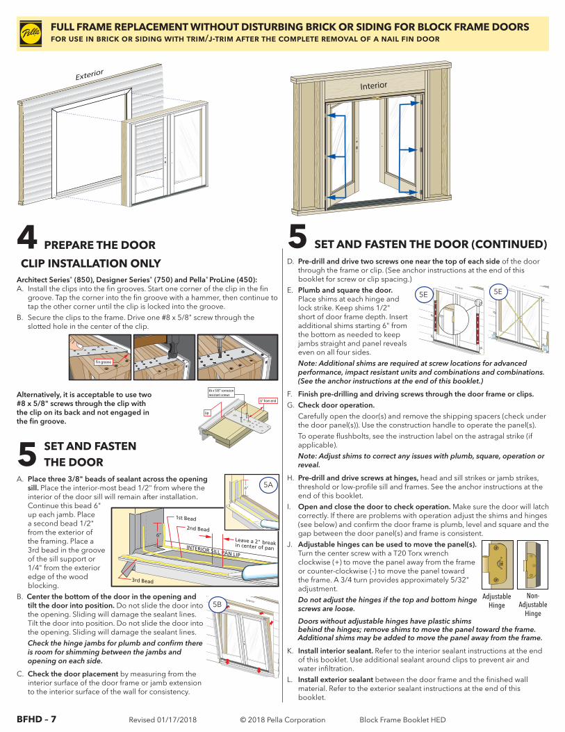
D. Pre-drill and drive two screws one near the top of each side of the door through the frame or clip. (See anchor instructions at the end of this booklet for screw or clip spacing.)
E. Plumb and square the door. Place shims at each hinge and lock strike. Keep shims 1/2" short of door frame depth. Insert additional shims starting 6" from the bottom as needed to keep jambs straight and panel reveals even on all four sides.Note: Additional shims are required at screw locations for advanced performance, impact resistant units and combinations and combinations. (See the anchor instructions at the end of this booklet.)
F. Finish pre-drilling and driving screws through the door frame or clips.G. Check door operation. Carefully open the door(s) and remove the shipping spacers (check under
the door panel(s)). Use the construction handle to operate the panel(s). To operate flushbolts, see the instruction label on the astragal strike (if
applicable).Note: Adjust shims to correct any issues with plumb, square, operation or reveal.
H. Pre-drill and drive screws at hinges, head and sill strikes or jamb strikes, threshold or low-profile sill and frames. See the anchor instructions at the end of this booklet.
I. Open and close the door to check operation. Make sure the door will latch correctly. If there are problems with operation adjust the shims and hinges (see below) and confirm the door frame is plumb, level and square and the gap between the door panel(s) and frame is consistent.
J. Adjustable hinges can be used to move the panel(s). Turn the center screw with a T20 Torx wrench clockwise (+) to move the panel away from the frame or counter-clockwise (-) to move the panel toward the frame. A 3/4 turn provides approximately 5/32" adjustment.Do not adjust the hinges if the top and bottom hinge screws are loose.
Doors without adjustable hinges have plastic shims behind the hinges; remove shims to move the panel toward the frame. Additional shims may be added to move the panel away from the frame.
K. Install interior sealant. Refer to the interior sealant instructions at the end of this booklet. Use additional sealant around clips to prevent air and water infiltration.
L. Install exterior sealant between the door frame and the finished wall material. Refer to the exterior sealant instructions at the end of this booklet.
A. Place three 3/8" beads of sealant across the opening sill. Place the interior-most bead 1/2" from where the interior of the door sill will remain after installation. Continue this bead 6" up each jamb. Place a second bead 1/2" from the exterior of the framing. Place a 3rd bead in the groove of the sill support or 1/4" from the exterior edge of the wood blocking.
B. Center the bottom of the door in the opening and tilt the door into position. Do not slide the door into the opening. Sliding will damage the sealant lines. Tilt the door into position. Do not slide the door into the opening. Sliding will damage the sealant lines.Check the hinge jambs for plumb and confirm there is room for shimming between the jambs and opening on each side.
C. Check the door placement by measuring from the interior surface of the door frame or jamb extension to the interior surface of the wall for consistency.
4 PREPARE THE DOOR
6“ from end
Lip
#6 x 5/8” corrosionresistant screws
Fin groove
CLIP INSTALLATION ONLYArchitect Series® (850), Designer Series® (750) and Pella® ProLine (450):A. Install the clips into the fin grooves. Start one corner of the clip in the fin
groove. Tap the corner into the fin groove with a hammer, then continue to tap the other corner until the clip is locked into the groove.
B. Secure the clips to the frame. Drive one #8 x 5/8" screw through the slotted hole in the center of the clip.
Alternatively, it is acceptable to use two #8 x 5/8" screws through the clip with the clip on its back and not engaged in the fin groove.
5 SET AND FASTEN THE DOOR (CONTINUED)
Exterior5B
Exterior
5EExterior
5E
5 SET AND FASTEN THE DOOR
Adjustable Hinge
Non- Adjustable
Hinge
EXTERIOR SILL PAN LIP
INTERIOR SILL PAN LIP
2nd Bead
Leave a 2" break in center of pan
1st Bead
3rd Bead
6”
12
3
6” 5A
Block Frame Booklet HED
BFHD – 8 Revised 01/17/2018 © 2018 Pella CorporationBFHD – 8 (ED)
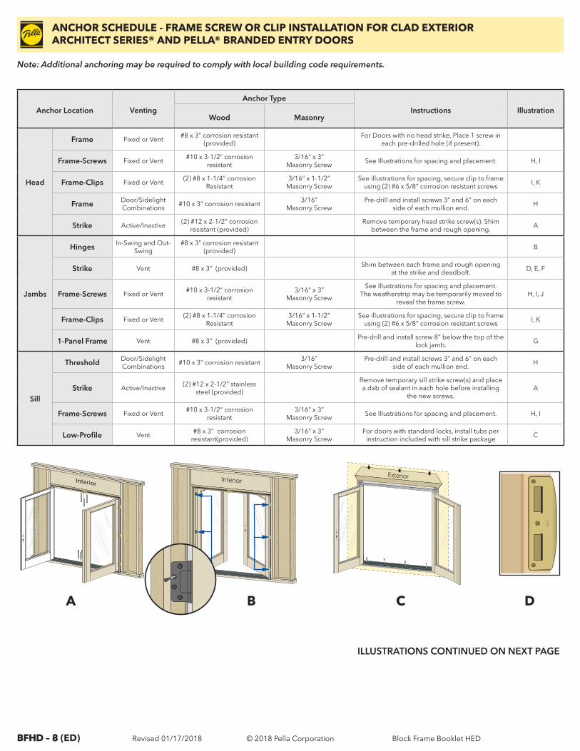
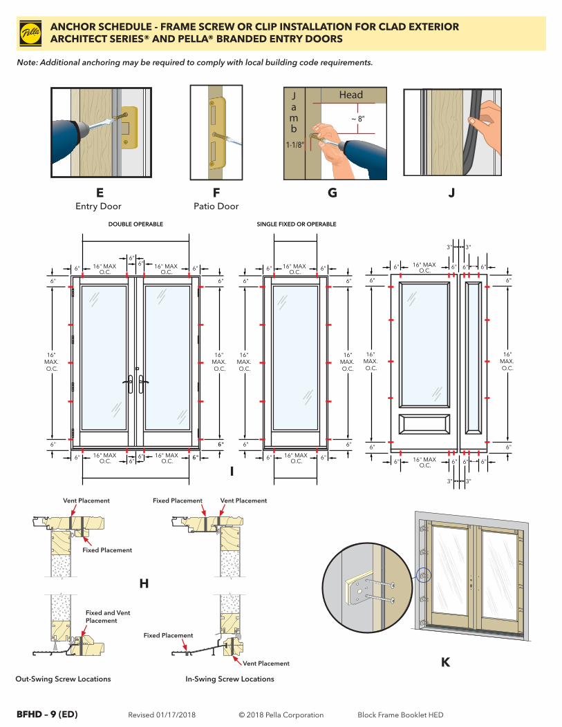
ANCHOR SCHEDULE - FRAME SCREW OR CLIP INSTALLATION FOR CLAD EXTERIORARCHITECT SERIES® AND PELLA® BRANDED ENTRY DOORS
Anchor Location Venting
Anchor Type
Instructions IllustrationWood Masonry
Head
Frame Fixed or Vent#8 x 3” corrosion resistant
(provided)For Doors with no head strike, Place 1 screw in
each pre-drilled hole (if present).
Frame-Screws Fixed or Vent#10 x 3-1/2” corrosion
resistant3/16” x 3”
Masonry ScrewSee Illustrations for spacing and placement. H, I
Frame-Clips Fixed or Vent(2) #8 x 1-1/4” corrosion
Resistant3/16” x 1-1/2”
Masonry ScrewSee illustrations for spacing, secure clip to frame
using (2) #6 x 5/8” corrosion resistant screwsI, K
Frame Door/Sidelight Combinations
#10 x 3” corrosion resistant 3/16”
Masonry ScrewPre-drill and install screws 3” and 6” on each
side of each mullion end.H
Strike Active/Inactive(2) #12 x 2-1/2” corrosion
resistant (provided)Remove temporary head strike screw(s). Shim
between the frame and rough opening.A
Jambs
Hinges In-Swing and Out-Swing
#8 x 3” corrosion resistant (provided)
B
Strike Vent #8 x 3” (provided)Shim between each frame and rough opening
at the strike and deadbolt.D, E, F
Frame-Screws Fixed or Vent#10 x 3-1/2” corrosion
resistant3/16” x 3”
Masonry Screw
See Illustrations for spacing and placement. The weatherstrip may be temporarily moved to
reveal the frame screw.H, I, J
Frame-Clips Fixed or Vent(2) #8 x 1-1/4” corrosion
Resistant3/16” x 1-1/2”
Masonry ScrewSee illustrations for spacing, secure clip to frame
using (2) #6 x 5/8” corrosion resistant screwsI, K
1-Panel Frame Vent #8 x 3” (provided)Pre-drill and install screw 8” below the top of the
lock jamb.G
Sill
Threshold Door/Sidelight Combinations
#10 x 3” corrosion resistant 3/16”
Masonry ScrewPre-drill and install screws 3” and 6” on each
side of each mullion end.H
Strike Active/Inactive(2) #12 x 2-1/2” stainless
steel (provided)
Remove temporary sill strike screw(s) and place a dab of sealant in each hole before installing
the new screws. A
Frame-Screws Fixed or Vent#10 x 3-1/2” corrosion
resistant3/16” x 3”
Masonry ScrewSee Illustrations for spacing and placement. H, I
Low-Profile Vent#8 x 3” corrosion
resistant(provided)3/16” x 3”
Masonry ScrewFor doors with standard locks, install tubs per
instruction included with sill strike packageC
InteriorInterior
Exterior
A B C D
ILLUSTRATIONS CONTINUED ON NEXT PAGE
Out-Swing Screw Locations
Note: Additional anchoring may be required to comply with local building code requirements.
Block Frame Booklet HED
BFHD – 9 Revised 01/17/2018 © 2018 Pella CorporationBFHD – 9 (ED)
ANCHOR SCHEDULE - FRAME SCREW OR CLIP INSTALLATION FOR CLAD EXTERIORARCHITECT SERIES® AND PELLA® BRANDED ENTRY DOORS
I
Out-Swing Screw Locations In-Swing Screw Locations
Vent Placement
Fixed Placement
Fixed and Vent Placement
Vent Placement
Vent Placement
Fixed Placement
Fixed Placement
Out-Swing Screw Locations In-Swing Screw Locations
H
K
6" 16" MAX O.C.
16" MAX O.C.
16" MAX O.C.
16" MAX O.C.
6"
6"
6"6"
6" 6"6"
DOUBLE OPERABLE
6"
6"
16" MAX. O.C.
6"
6"
16" MAX. O.C.
16" MAX O.C.
16" MAX O.C.
6" 6"
6" 6"
SINGLE FIXED OR OPERABLE
6"
6"
16"MAX. O.C.
6"
6"
16" MAX. O.C.
6"
6"
16"MAX. O.C.
6"
6"
16" MAX. O.C.
16" MAX O.C.
6" 6"
3" 3"
6"6"
16" MAX O.C.
6" 6"
3" 3"
6"6"
G J
Head
~ 8”
Jamb
1-1/8”
E FPatio DoorEntry Door
Note: Additional anchoring may be required to comply with local building code requirements.
Block Frame Booklet HED
BFHD – 10 Revised 01/17/2018 © 2018 Pella Corporation
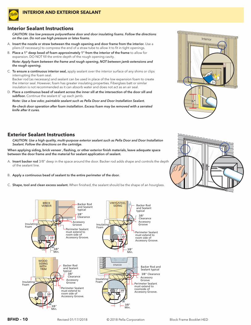
Interior Sealant InstructionsCAUTION: Use low pressure polyurethane door and door insulating foams. Follow the directions on the can. Do not use high pressure or latex foams.
A. Insert the nozzle or straw between the rough opening and door frame from the interior. Use a pliers (if necessary) to compress the end of a straw tube to allow it to fit in tight openings.
B. Place a 1" deep bead of foam approximately 1" from the interior of the frame to allow for expansion. DO NOT fill the entire depth of the rough opening cavity. Note: Apply foam between the frame and rough opening, NOT between jamb extensions and the rough opening.
C. To ensure a continuous interior seal, apply sealant over the interior surface of any shims or clips interrupting the foam seal. Backer rod (as necessary) and sealant can be used in place of the low expansion foam to create the interior seal. However, foam has greater insulating properties. Fiberglass batt or similar insulation is not recommended as it can absorb water and does not act as an air seal.
D. Place a continuous bead of sealant across the inner sill at the intersection of the door sill and subfloor. Continue the sealant 6" up each jamb.Note: Use a low odor, paintable sealant such as Pella Door and Door Installation Sealant.
Re-check door operation after foam installation. Excess foam may be removed with a serrated knife after it cures.
Exterior Sealant InstructionsCAUTION: Use a high quality, multi-purpose exterior sealant such as Pella Door and Door Installation Sealant. Follow the directions on the cartridge.
When applying siding, brick veneer , flashing, or other exterior finish materials, leave adequate space between the door frame and the material for sealant application of sealant.
A. Insert backer rod 3/8" deep in the space around the door. Backer rod adds shape and controls the depth of the sealant line.
B. Apply a continuous bead of sealant to the entire perimeter of the door.
C. Shape, tool and clean excess sealant. When finished, the sealant should be the shape of an hourglass.
Interior
6"
BRICKVENEER
3/8" Clearance
Backer Rod and Sealant typical
Insulating Foam
Perimeter Sealant must extend to room side of Accessory Groove.
Accessory Groove
3/8"Min.
3/8"
3/8"Min.
3/8"
VINYL/STEELSIDING
3/8" Clearance
Backer Rod and Sealant typical
InsulatingFoam
Perimeter Sealant must extend to room side of Accessory Groove.
Accessory Groove
STUCCO
3/8" Clearance
Backer Rod andSealant typical
Perimeter Sealant must extend to roomside of Accessory Groove.
Accessory GrooveInsulating
Foam
3/8"Min.
3/8"
InsulatingFoam
Perimeter Sealant must extend to room side of Accessory Groove.
WOOD SIDINGWITH TRIM
3/8" Clearance
Accessory Groove
Backer Rod and Sealant typical
3/8"Min.
3/8"
INTERIOR AND EXTERIOR SEALANT
Block Frame Booklet HED
BFHD – 11 Revised 01/17/2018 © 2018 Pella CorporationBFHD – 11 (ED)
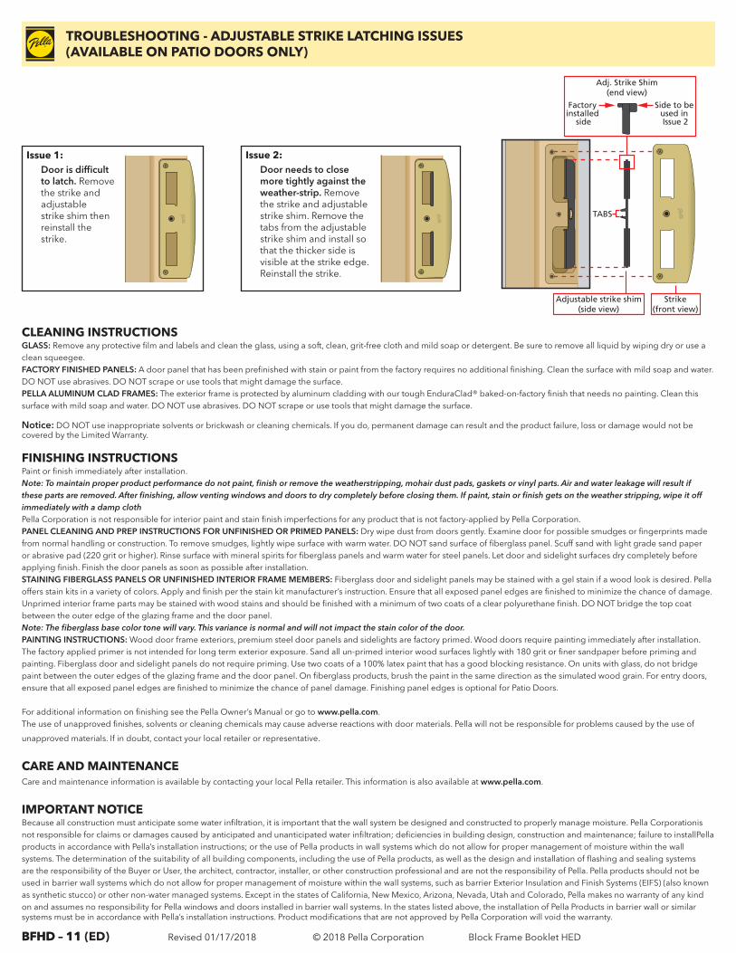
TABS
Adjustable strike shim(side view)
Strike(front view)
Adj. Strike Shim(end view)
Factory installed
side
Side to be used in Issue 2
Issue 2: Door needs to close
more tightly against the weather-strip. Remove the strike and adjustable strike shim. Remove the tabs from the adjustable strike shim and install so that the thicker side is visible at the strike edge. Reinstall the strike.
Issue 1: Door is difficult
to latch. Remove the strike and adjustable strike shim then reinstall the strike.
TROUBLESHOOTING - ADJUSTABLE STRIKE LATCHING ISSUES(AVAILABLE ON PATIO DOORS ONLY)
CLEANING INSTRUCTIONSGLASS: Remove any protective film and labels and clean the glass, using a soft, clean, grit-free cloth and mild soap or detergent. Be sure to remove all liquid by wiping dry or use a clean squeegee.FACTORY FINISHED PANELS: A door panel that has been prefinished with stain or paint from the factory requires no additional finishing. Clean the surface with mild soap and water. DO NOT use abrasives. DO NOT scrape or use tools that might damage the surface.PELLA ALUMINUM CLAD FRAMES: The exterior frame is protected by aluminum cladding with our tough EnduraClad® baked-on-factory finish that needs no painting. Clean this surface with mild soap and water. DO NOT use abrasives. DO NOT scrape or use tools that might damage the surface.
Notice: DO NOT use inappropriate solvents or brickwash or cleaning chemicals. If you do, permanent damage can result and the product failure, loss or damage would not be covered by the Limited Warranty.
FINISHING INSTRUCTIONSPaint or finish immediately after installation.Note: To maintain proper product performance do not paint, finish or remove the weatherstripping, mohair dust pads, gaskets or vinyl parts. Air and water leakage will result if these parts are removed. After finishing, allow venting windows and doors to dry completely before closing them. If paint, stain or finish gets on the weather stripping, wipe it off immediately with a damp clothPella Corporation is not responsible for interior paint and stain finish imperfections for any product that is not factory-applied by Pella Corporation. PANEL CLEANING AND PREP INSTRUCTIONS FOR UNFINISHED OR PRIMED PANELS: Dry wipe dust from doors gently. Examine door for possible smudges or fingerprints made from normal handling or construction. To remove smudges, lightly wipe surface with warm water. DO NOT sand surface of fiberglass panel. Scuff sand with light grade sand paper or abrasive pad (220 grit or higher). Rinse surface with mineral spirits for fiberglass panels and warm water for steel panels. Let door and sidelight surfaces dry completely before applying finish. Finish the door panels as soon as possible after installation.STAINING FIBERGLASS PANELS OR UNFINISHED INTERIOR FRAME MEMBERS: Fiberglass door and sidelight panels may be stained with a gel stain if a wood look is desired. Pella offers stain kits in a variety of colors. Apply and finish per the stain kit manufacturer’s instruction. Ensure that all exposed panel edges are finished to minimize the chance of damage. Unprimed interior frame parts may be stained with wood stains and should be finished with a minimum of two coats of a clear polyurethane finish. DO NOT bridge the top coat between the outer edge of the glazing frame and the door panel.Note: The fiberglass base color tone will vary. This variance is normal and will not impact the stain color of the door.PAINTING INSTRUCTIONS: Wood door frame exteriors, premium steel door panels and sidelights are factory primed. Wood doors require painting immediately after installation. The factory applied primer is not intended for long term exterior exposure. Sand all un-primed interior wood surfaces lightly with 180 grit or finer sandpaper before priming and painting. Fiberglass door and sidelight panels do not require priming. Use two coats of a 100% latex paint that has a good blocking resistance. On units with glass, do not bridge paint between the outer edges of the glazing frame and the door panel. On fiberglass products, brush the paint in the same direction as the simulated wood grain. For entry doors, ensure that all exposed panel edges are finished to minimize the chance of panel damage. Finishing panel edges is optional for Patio Doors.
For additional information on finishing see the Pella Owner’s Manual or go to www.pella.com.The use of unapproved finishes, solvents or cleaning chemicals may cause adverse reactions with door materials. Pella will not be responsible for problems caused by the use of
unapproved materials. If in doubt, contact your local retailer or representative.
CARE AND MAINTENANCECare and maintenance information is available by contacting your local Pella retailer. This information is also available at www.pella.com.
IMPORTANT NOTICEBecause all construction must anticipate some water infiltration, it is important that the wall system be designed and constructed to properly manage moisture. Pella Corporationis not responsible for claims or damages caused by anticipated and unanticipated water infiltration; deficiencies in building design, construction and maintenance; failure to installPella products in accordance with Pella’s installation instructions; or the use of Pella products in wall systems which do not allow for proper management of moisture within the wall systems. The determination of the suitability of all building components, including the use of Pella products, as well as the design and installation of flashing and sealing systems are the responsibility of the Buyer or User, the architect, contractor, installer, or other construction professional and are not the responsibility of Pella. Pella products should not be used in barrier wall systems which do not allow for proper management of moisture within the wall systems, such as barrier Exterior Insulation and Finish Systems (EIFS) (also known as synthetic stucco) or other non-water managed systems. Except in the states of California, New Mexico, Arizona, Nevada, Utah and Colorado, Pella makes no warranty of any kind on and assumes no responsibility for Pella windows and doors installed in barrier wall systems. In the states listed above, the installation of Pella Products in barrier wall or similar systems must be in accordance with Pella’s installation instructions. Product modifications that are not approved by Pella Corporation will void the warranty.
Block Frame Booklet HED
BFHD – 12 Revised 01/17/2018 © 2018 Pella Corporation
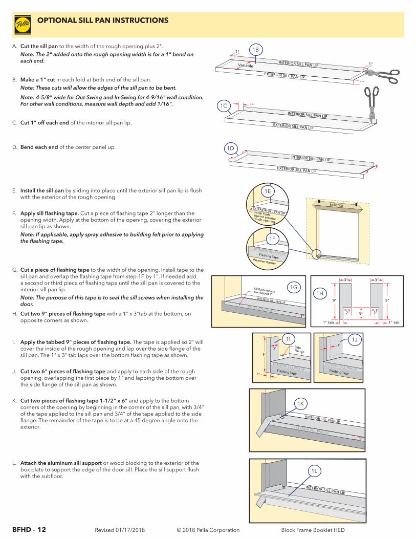
OPTIONAL SILL PAN INSTRUCTIONS
A. Cut the sill pan to the width of the rough opening plus 2".Note: The 2" added onto the rough opening width is for a 1" bend on each end.
B. Make a 1" cut in each fold at both end of the sill pan.Note: These cuts will allow the edges of the sill pan to be bent.
Note: 4-5/8" wide for Out-Swing and In-Swing for 4-9/16" wall condition. For other wall conditions, measure wall depth and add 1/16".
C. Cut 1" off each end of the interior sill pan lip.
D. Bend each end of the center panel up.
INTERIOR SILL PAN LIP
EXTERIOR SILL PAN LIP 1"
1"
Variable1"
INTERIOR SILL PAN LIP
EXTERIOR SILL PAN LIP
1"
INTERIOR SILL PAN LIP
EXTERIOR SILL PAN LIP
Exterior EXTERIOR SILL PAN LIP Install flush against exterior rough opening.
EXTERIOR SILL PAN LIP Flashing Tape Weather Barrier
9"
3"
1" tab
3"
2"
9"
1" tab
3"
2"
EXTERIOR SILL PAN LIPFlashing Tape
9"
1"
2" SideFlange
EXTERIOR SILL PAN LIPFlashing Tape
1"
1B
1C
1D
1E
1F
1H
1I 1J
EXTERIOR SILL PAN LIP
INTERIOR SILL PAN LIP
1"
EXTERIOR SILL PAN LIP
INTERIOR SILL PAN LIP
1K
1L
EXTERIOR SILL PAN LIP
INTERIOR SILL PAN LIP
1"
Sill �ashing tape overlapped 1"
1G
E. Install the sill pan by sliding into place until the exterior sill pan lip is flush with the exterior of the rough opening.
F. Apply sill flashing tape. Cut a piece of flashing tape 2" longer than the opening width. Apply at the bottom of the opening, covering the exterior sill pan lip as shown.Note: If applicable, apply spray adhesive to building felt prior to applying the flashing tape.
G. Cut a piece of flashing tape to the width of the opening. Install tape to the sill pan and overlap the flashing tape from step 1F by 1". If needed add a second or third piece of flashing tape until the sill pan is covered to the interior sill pan lip.Note: The purpose of this tape is to seal the sill screws when installing the door.
H. Cut two 9" pieces of flashing tape with a 1" x 3"tab at the bottom, on opposite corners as shown.
I. Apply the tabbed 9" pieces of flashing tape. The tape is applied so 2" will cover the inside of the rough opening and lap over the side flange of the sill pan. The 1" x 3" tab laps over the bottom flashing tape as shown.
J. Cut two 6" pieces of flashing tape and apply to each side of the rough
opening, overlapping the first piece by 1" and lapping the bottom over the side flange of the sill pan as shown.
K. Cut two pieces of flashing tape 1-1/2" x 6" and apply to the bottom corners of the opening by beginning in the corner of the sill pan, with 3/4" of the tape applied to the sill pan and 3/4" of the tape applied to the side flange. The remainder of the tape is to be at a 45 degree angle onto the exterior.
L. Attach the aluminum sill support or wood blocking to the exterior of the box plate to support the edge of the door sill. Place the sill support flush with the subfloor.
Block Frame Booklet HED