pendulum spreaders - gearmore · 5 fertilizer spreader use ... these pendulum spreaders are...
TRANSCRIPT

PENDULUMSPREADERS
Operation, Service & Parts Manual
For Models PDC400, PDV500,PDV600 & PDHV800
February 2009
Form: PDVPendSprdr

TABLE OF CONTENTS
SECTION DESCRIPTION ..................................................PAGE 1 Introduction ............................................................................................. 1
2 General Information ........................................................................... 1 - 4 2.1 Using the Manual ............................................................................................1 2.2 Serial Number Plate ........................................................................................2 2.3 Machine Characteristics ...........................................................................2 - 3 2.4 Technical Specifi cations .................................................................................4
3 Important Safety Information ............................................................5 - 9 3.1 General Advice ..........................................................................................5 - 6 3.2 Connection to Tractor ....................................................................................7 3.3 Operation of Machine ...................................................................................7 3.4 Transporting ....................................................................................................8 3.5 Safety Decals ....................................................................................................9
4 Connections .....................................................................................10 - 12 4.1 Connection Checklist ...................................................................................10 4.2 Raising Ability ................................................................................................10 4.3 3-Point Hitch Connection ...........................................................................11 4.4 Driveline Installation ....................................................................................12 4.5 Optional Hydraulic System Connection ....................................................12 4.6 PDC400 Assembly ................................................................................13 - 14
5 Fertilizer Spreader Use ....................................................................15 - 21 5.1 Correct Distribution Recommendations ...................................................15 5.2 Spreading Width Adjustment ......................................................................15 5.3 Using Adjustment Wrench ..........................................................................16 5.4 Spreading Quantity Adjustment .........................................................17 - 18 5.5 Hopper Load .................................................................................................19 5.6 Spreading In Field .........................................................................................20 5.7 Spreading Mistakes .......................................................................................21
6 General Maintenance ...................................................................... 22 - 24 6.1 Lubrication .....................................................................................................23 6.2 Pendulum Placement ....................................................................................23 6.3 Storage ............................................................................................................24 6.4 Spare Parts ......................................................................................................24
7 Parts Breakdown ............................................................................. 25 - 33 7.1 PDV500/600 Complete Frame ..................................................................25 7.2 PDHV800 Complete Frame .......................................................................26 7.3 Gearbox ..................................................................................................27 - 30 7.4 Optional Spouts ............................................................................................31 7.5 PDV500/600 Hyd. System Optional .........................................................32 7.6 PDHV800 Hyd. System Optional ..............................................................33
8 Limited Warranty ...................................................................................34

We would like to thank you for purchasing a Gearmore product and we assure you that you have made a good choice, as now you have a very high quality machine. Please follow all instructions contained in this manual for a long and trustworthy machine life.
These pendulum spreaders are machines used for the distribution of solid, granular fertilizers and seeds in the fi eld.
It is recommended to carefully read this operator's manual of use and maintenance and follow the recommendations to help ensure safe and effi cient operation with and on the machine.
This manual has been written in order to give the customer all the information and safety rules on the machine, as well as use and maintenance instructions.
The manual must always be handy, so as to consult it in order to check the operational cycle. If it gets lost or damaged, it will be necessary to ask for a substitute copy.
In case of some diffi culties of interpretation on texts or tables, or if the drawings/sketches are not clear enough, please get immediate assistance from your dealer.
2. GENERAL INFORMATION
2.1 USING THE MANUAL: This manual gives all the information for the use and maintenance of the machine. The good working and its life depends on the good maintenance and attention during the use. Some pictures in this manual show details or accessories that could be different from those of your machine, some components could be removed, in order to assure the clearness of the pictures. Decals are put on the machine and the operator shall see to keep them in a perfect visual condition, replacing them when they are not readable anymore.
SAFETY SIGNALS This symbol is used in this manual to draw your attention to the safety and good work of the machine. therefore, it is necessary to observe all the written rules in order to prevent any accident or damages.
We recommend the use of original spare parts and accessories.Not using original parts, besides voiding the guarantee, could be dangerous, reducing the life and the performances of the machine.
It is IMPORTANT to read this manual carefully before
operating the spreader!
1. INTRODUCTION
1

2. GENERAL INFORMATION
2
2.2 SERIAL NUMBER PLATE:
A name plate is fi xed on the frame of every machine showing the model, the serial number and the year of construction of the machine.
When some spare parts are required, it is always necessary to refer to the type of machine, to the serial number and to the manufacturing year.
Location of the name plate on the machine
2.3 MACHINE CHARACTERISTICS:
The great spreading precision of these kind of fertilizer spreaders lets them be used in different applications, both for specifi c cultivations and in golf courses.
Our spreaders can rely on a huge range of models adaptable with tractors of any power.
The upper parts of the gearbox are made of stainless steel in order to increase its long life and prevent corrosion.
It is possible to settle the gearbox on two different orders of spreading widths from 30 to 40 feet or from 40 to 50 feet by using a special key. (see spreader use section)

2. GENERAL INFORMATION
3
Besides the standard pendulum, several other spouts are available for different applications, such as for the spreading in which the spreading width is limited from a minimum of 3 feet to a maximum of 26 feet for its use on the vineyards, the orchards, or in the parks.
The hopper is fi berglass reinforced plastic that cannot rust (except Model PDC400, which is poly).
The paint on the frame is made by a water base varnish and is baked at 150° with the application of the primer bath, assuring great protection and a long life for the machine.
The feeding of the disc is by gravity through the exits, located on the bottom of the hopper, that can be opened or closed by a mechanical or hydraulic system (optional). The dosage of the fertilizer is made by operating on the opening section by an adjusting rod that slides on a threaded pin with a graduate scale.
For the more powdered fertilizers, it is possible to settle an agitator/mixer on the bottom of the hopper to avoid the formation of lumps in the fertilizer.
All models are 3-point hitch, 540 r.p.m. PTO speed.
Pendulum Spreading width adjustment key
Standard Agitator Optional Agitator Crown Opening Lever
2. GENERAL INFORMATION
4
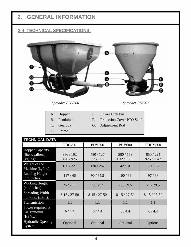
2.4 TECHNICAL SPECIFICATIONS:
Spreader PDV500 Spreader PDC400
A. Hopper E. Lower Link Pin B. Pendulum F. Protection Cover PTO Shaft C. Gearbox G. Adjustment Rod D. Frame
TECHNICAL DATAPDC400 PDV500 PDV600 PDHV800
Hopper Capacity(liters/gallons):(kg/lbs):
386 / 102420 / 925
480 / 127523 / 1153
580 / 153632 / 1393
850 / 224926 / 5042
Weight of theMachine (kg/lbs):
100 / 221 130 / 287 142 / 313 170 / 375
Loading Height(cm/inches):
117 / 46 90 / 35.5 100 / 39 97 / 38
Working Height(cm/inches):
75 / 29.5 75 / 29.5 75 / 29.5 75 / 29.5
Spreading Widthmin-max (mt/ft):
8-15 / 27-50 8-15 / 27-50 8-15 / 27-50 8-15 / 27-50
Transmission: 1:1 1:1 1:1 1:1Power required at540 rpm/min(HP/kw):
6 / 4.4 6 / 4.4 6 / 4.4 6 / 4.4
Hydraulic Opening System:
Optional Optional Optional Optional

3. IMPORTANT SAFETY INFORMATION
5
THE FOLLOWING SAFETY RECOMMENDATIONS ARE TO SAFEGUARD YOU; THEREFORE IT IS NECESSARY TO READ THEM CAREFULLY, MEMORIZING
AND ALWAYS APPLYING THEM.
The present warnings in this manual regard exclusively the allowed uses and reasonably foreseeable. All below instructions must be integrated by common sense and by the experience of who works, indispensable measures to prevent accidents.
The machine must be used by a single operator. It is forbidden for use by under age individuals.
All the listed instructions must be carefully respected.
Possible changes on the machine, not preventively authorized by the manufacturer (by written copy), exclude his responsibility.
Check the correct functioning of the machine, before each use.
3.1 GENERAL ADVICE: ● Read carefully this manual before proceeding to start, operate, employ, or maintenance on the machine. ● Watch, in addition to the warnings of this manual, all the safety, accident prevention rules and of general nature. ● The manual must always be handy, so as to consult it in order to check working cycle and safety information. In case of loss or damage, it will be necessary to ask for a replacement copy.
ATTENTION! Any maintenance work, regulation and cleaning must be done with the machine on the ground (in stable conditions), turning off the tractor engine and removing the key.
● Read carefully the safety signal words applied on the machine and follow the instructions. In case of wear and tear or insuffi cient readability of the safety signal words, clean them up or replace them, placing the signal words in the right position, as shown on page 9.
ATTENTION! - WARNING! The operator, during the period of use, maintenance, repair, handling or storing of the machine, must wear accident prevention shoes and safety gloves. Moreover, if it is necessary he must wear suitable hearing protections such as earmuffs or earplugs, dust masks and protective glasses.
● During loading phase, there is the danger of powder inhalation produced by fertilizer mixing. It is suggested to use tractors with fi lters on the ventilation system of the cabin, to use suitable safety systems of breathing, like powder masks or masks with fi lter.

3. IMPORTANT SAFETY INFORMATION
6
● The machine is designed for being used by a single operator who, during the use, must always stay in the stationing control on the tractor. ● Never work with this machine if you are tired, sick or after having taken alcohol, drugs or medicines.
DANGER! It is forbidden to climb or to transport somebody when the machine is in motion. Do not get in the hopper for any reason. Do not ride on implement.
● Keep the machine cleaned up from foreign bodies (debris, tools, miscellaneous), as they could damage the operations or the operator. Generally the fertilizers are rather corrosive. For this reason, it is important that any particle of the fertilizer stay in the machine for a long period of time. Clean the hopper and the distributor after each use of the machine.
● If during cleaning operations air or water with pressure is used, it is necessary to wear glasses and safety masks keeping all persons and animals away from the machine.
● Before connecting the machine to the tractor or to other self-moving means check that this is in good condition and that brakes work correctly, especially if you work on sloping grounds.
● Switch off the machine from tractor only on a compact and level ground (with empty hopper), checking that the machine is stable.
WARNING! During transport operations, stocking and employment of the fertilizers, the operators must follow all the label indications and particularly to the content of the written risks and the precaution suggestions.
ATTENTION! The manufacturer is not responsible for damages caused by improper and unforeseen use of the machine.
The Manufacturer is not responsible in case of:
~ Improper use of the machine, use by non trained staff. ~ Serious defi ciencies in the foreseen maintenance. ~ Changes or not allowed interventions. ~ Use of not original or specifi c spare parts. ~ Total or partial inobservance of the instructions. ~ Inobservance of the common safety rules during work. ~ Unusual cases.

3. IMPORTANT SAFETY INFORMATION
7
3.2 CONNECTION OF THE MACHINE TO THE TRACTOR: ● The third hitch point of the tractor and the fertilizer spreader must coincide or must be adapted. ● Make sure that the PTO shaft is engaged in right way after every linkage operation of the machine and that it does not come uncoupled when the machine is lowered in order to fi ll the hopper up.
ATTENTION! WARNING! Check that the protections of the PTO shaft are complete and in good conditions.
● In case of breaking or deterioration of the PTO shaft protections, please replace them immediately. ● When the machine is not linked to the power unit, the PTO shaft must be placed on the appropriate support. ● The presence of the machine can infl uence the maneuverability of the tractor, in particular during transport.
ATTENTION! Do not come, for any reason, between the tractor and the fertilizer spreader when the engine is running and the power take-off is on.
3.3 OPERATION OF THE MACHINE: ● Make a check of the machine before switching it on. Start to work only if the machine is in perfect condition. ● Before using the machine, please be sure that all the safety devices are correctly installed and in good working condition; in case of breakdowns or damages to the protections, please replace them immediately.
ATTENTION! During work, please make sure that no person or animal is allowed within a radius of 30 yards. When you work in proximity of roads or public places, it is ABSOLUTELY OBLIGATORY to keep away persons and to increase the precautions.
ATTENTION! Anybody who comes up to the machine is in a danger area, therefore he becomes "AN EXPOSED PERSON". The operator must prevent anybody from coming into the danger area and to work with the maximum caution. If somebody comes up, please stop immediately the tractor engine.
● Before every use of the spreader, please check the condition of the pendulum. Check that all the fi xing components (screws, bolts, etc) are in and tightened. ● The machine must never be unattended when it is moving. ● Keep always the machine in good operating condition and perform regular maintenance.

3. IMPORTANT SAFETY INFORMATION
8
3.4 TRANSPORTING:
ATTENTION! Please follow scrupulously the highway code in force in the area of use. During moves on public roads, it is obligatory to empty the hopper.
● Remember that during moving on public roads, special attention must be done, besides to possible and special regulations noted on the registration book of the tractor, choosing an appropriate speed especially when the street is crowded, winding or sloping.
● If the spreader hides with its shape the back signaling lights of the tractor, it is necessary to put a lights bar and/or some back signaling signs.
ATTENTION! During the moving on the road, the warning fl asher, yellow or orange, assembled on the tractor must always be in function also during the day.
ATTENTION! During transport with raised machine, please always check that the control lever of the rear hitch is locked, in order to avoid the accidental lowering of the machine.

3. IMPORTANT SAFETY INFORMATION
9
3.5 SAFETY DECALS: ATTENTION! Be sure that the safety labels are readable. Clean them using a cloth, water and soap. Replace the damaged labels placing them in the right position, as subsequently described.
The safety signs on the machine supply the most important indications; their observance helps your safeness.
1. ATTENTION! Before making any operation on the machine, 2. ATTENTION! - DANGER stop the engine of the tractor or entangling and dragging. Do of the self-moving means, remove not put hands near the running the key, put on the parking brake gearbox. and read carefully the operator's manual.
3. ATTENTION! Check the 4. ATTENTION! - DANGER sense of rotation and the number of crushing. Do not stop between of revolutions (540 rpm) of the the machine and tractor when the tractor power before placing the tractor engine is running. PTO shaft.
5. ATTENTION! - DANGER Possible throwing of material 6. ATTENTION! - DANGER and/or objects, please do not of shearing. Do not approach stop or come up to the machine. limbs to the pendulum when Keep a safety distance of 30 ft. the machine is running. at least, from the machine.
7. ATTENTION! Use the individual Protection Devices as required.
Placement of safety decals on machine:

4. CONNECTIONS
10
4.1 CONNECTIONS CHECKLIST:
The machine can be delivered all assembled or not (in this case follow the assembling instructions enclosed). In both cases, before using the spreader it is necessary to verify that all the fi xing elements (screws, nuts, washers, etc.) are well locked and make sure that all the safety devices are located in their right position.
Verify that the gearbox is fi xed to the machine frame by 4 screws: two longer (hexagonal head 12 x 50) in the front part, at the PTO shaft connection side, and two shorter (hexagonal head 12 x 40) back, at the pendulum side.
Before coupling the machine to the 3-point hitch, position the safety devices to the tractor, so that it is not possible to involuntarily and/or accidentally raise or lower the arms.
The 3-point hitch of the tractor and of the machine must coincide or must be adapted.
In proximity of arms rods of the back hitch of the tractor, there is the danger of wounding, because of crushing and cutting points.
Do not use the external controls for the lifting of the machine. During transport position, block the lateral stop of the rods.
4.2 CHECK THE RAISING ABILITY OF THE TRACTOR:
DANGER! It is obligatory to check the raising ability and the stability of the tractor (before carrying out the connection with the machine) in order to avoid the overturning and/or the loss of wheels grip.

4. CONNECTIONS
11
4.3 CONNECTION TO THE 3-POINT HITCH OF THE TRACTOR:
ATTENTION! Every time that somebody comes down from the tractor, it is necessary to disconnect the PTO shaft, stop the engine and engage the parking brake.
For the connection of the machine to the tractor, please operate in the following way:
● Step backwards with the tractor until arriving in proximity of the lower connections of the fertilizer spreader. ● Fix the lower connections of the tractor to the pins of the machine and lock them with the safety plugs. ● Connect the upper linkage of the machine to the 3-point hitch of the tractor putting the appropriate pin and block the anti- unscrewing device of the 3-point hitch. ● Raise the machine a few inches off the ground and operate on the lateral ties of the lifter bars and on the two turnbuckles, in order to block the lateral movement, so as to prevent excessive oscillations during the working phase.
The machine must be positioned, through the raising of the lower connections of the tractor, so that the land distance from the lower extremity of the pendulum is approximately 30".
To obtain a regular distribution, it is important that the pendulum is in horizontal position compared to the land.
● After having made these operations, the PTO shaft must be linked to the smooth shaft of the gearbox of the machine (covered by a safety cowling) and also to the tractor power take-off.
ATTENTION! The PTO shaft must always be engaged last to the tractor power take-off and disengaged fi rst, when you stop working.
The PDHV800 spreader is equipped with a quick attachment (A). In order to simplify the connection operation we suggest to assemble the bar (A) on the lower arms of the tractor's lifter. Afterwards, in order to connect the machine, open the connec-tion hooks (B) by unloosing the fi xing nuts (C), bring the tractor nearer to put the bar connected to the lifter in the connection hooks' slots, lock them tight and fi x them by the bolts. The bar (A) on larger model is raised (as shown in the picture) in order to avoid the PTO shaft could hit with it during the working.

4. CONNECTIONS
12
4.4 DRIVELINE INSTALLATION: Before using the PTO shaft, please consult the use and maintenance manual attached to the PTO shaft.For a correct and safe operation of the machine, please use exclusively PTO shafts with CE mark.
Please use PTO shafts with integral shields. ● Grease periodically the PTO shaft following the instruction supplied by the PTO shaft manufacturer (see the use and maintenance manual of the PTO shaft). ● Observe the sense of assembly of the PTO shaft, as indicated by the manufacturer and shown on the outer cover of the shield (tractor drawing on the external tube of the PTO shaft towards the power take-off of the same tractor). ● Fasten the safety anti-rotation chains after making sure that the connection between the PTO shaft and the gearbox is well locked. Use for this connection a hexagonal head screw 8.8 10 x 70 UNI 5737 with the relative nut.
ATTENTION! Check the rotation sense and the speed regulation of the power take-off of the tractor to be at 540 r.p.m., as the machine is projected for this kind of speed.
The length of the PTO shaft must be adapted to the type of tractor used.When the PTO shaft is released from the power take-off of the tractor, it must ALWAYS be laid on the appropriate support.We are not responsible for damages caused by an incorrect assembly and use of the PTO shaft.
4.5 HYDRAULIC SYSTEM INSTALLATION (OPTIONAL):
In order to recognize the element used, please refer to the tables 08 and 09 of the parts breakdown sections.
1. Assemble the connection plate for hydraulic opening system (ref. 8) on the gearbox by using the screw and the nut (C) already on the gearbox. 2. Fixing the hydraulic cylinder (ref. 1) to the connection plate (ref. 8) by using the screw (ref. 4) hexagonal head 8 x 30 (mod. PDV500/600) or hexagonal head 8 x 25 (mod. PDV800), the self- locking nut M8 (ref. 6), the two washers 8 x 17 (ref. 7) and the bushing 13 x 8 x 7 (ref. 9). 3. The hydraulic cylinder stem must be connected to the lever plate in the hole B. Insert the screw hexagonal head 12 x 60 (ref. 3) in the hole B, screw up the nut M12 (ref. 10) insert the screw in one of the two cylinder holes and fi x it by the self-locking nut M12 (ref. 5).

4. CONNECTIONS
13
4.6 PDC400 ASSEMBLY INSTRUCTIONSSTEP 1: Set frame in working position (Fig. 1).
Fig. 1
STEP 2: Put calibration rod (Ref. B) on gearbox assembly (Ref. A - Fig. 2).
STEP 3: Mount gearbox assembly (Ref. A - Fig. 2) to main frame (Fig. 3).
Fig. 2 Fig. 3
STEP 4: Mount extension bracket (Ref. C - Fig. 4) to main frame.
Fig. 4
STEP 5: Bolt adjustment handle (Ref. D - Fig. 5) to extension bracket (Ref. C - Fig. 4) using poly bushing, spring, bolt, washer and nut.
Fig. 5
Ref. A
Ref. B
Ref. C
Ref. D

4. CONNECTIONS
14
STEP 6: Slide adjustment handle (Ref. D) into calibration rod (Ref.B - Fig. 6) and install bolt and nut.
Fig. 6
STEP 7: Mount lower lift pins (Ref. E - Fig. 7) onto main frame.
STEP 8: Mount and center hopper (Ref. F - Fig. 8) in gearbox assembly. After centered, drill 3 holes in hopper and install bolts. Fig. 7
STEP 9: Install pendulum tube to gearbox assembly (Ref. A).
STEP 10: Measure and install PTO driveline to gearbox assembly (Ref. A). Fig. 8
STEP 11: Install all safety and rate decals.
Ref. E
Ref. F

ATTENTION! Before use, please check that gears are adequately greased (see lubrication section)
ATTENTION! During the use of the machine, please be sure that for a radius of 30 yards there are not any persons or animals. If somebody comes up, please immediately stop the tractor engine.
5.1 RECOMMENDATIONS FOR A CORRECT DISTRIBUTION:
● Please always test the lbs. per acre that you wish to spread before starting to work. ● Do not engage the PTO shaft when the tractor is in acceleration, because it will start the pendulum spreading. Lower the engine revolutions at the minimum and after that speed up gradually till obtaining a speed of 540 r.p.m. ● Open exits only when the right speed is achieved. ● Avoid spreading fertilizer on windy days, in order to improve the uniformity of the distribution.
5.2 SPREADING WIDTH ADJUSTMENT: The spreading angle can be reduced for narrow spreading. The spreader is set at the factory for the maxi-mum spreading angle of 56 degrees, position 1 for maximum spreading of 46 feet. You can reduce the degrees to 48° for spreading as narrow as 9 feet. When the arrow on the adjuster points away from the driveshaft, you achieve the widest angle. When the arrow points to the driveshaft, the spout will move to the narrowest angle.
For better accuracy in narrow rows, it is recommended that you purchase one of the narrow row spouts.
5. FERTILIZER SPREADER USE
15

5. FERTILIZER SPREADER USE
16
5.3 USING THE ADJUSTMENT WRENCH:
1. Remove the plug (3) from spreading cover (see drawing above). 2. Use the input shaft to rotate the fl ywheel (4) until the adjuster faces the hole. 3. Place the wrench (5) on the adjuster. 4. Use the wrench to push in the adjusting spring. 5. Rotate the wrench 180 degrees to the right to obtain the narrowest spread degrees. To the left is maximum, which is set at the factory. 6. Return the wrench making sure the adjuster is locked in place. 7. Replace the plug in the cover.

5. FERTILIZER SPREADER USE
17
5.4 SPREADING QUANTITY ADJUSTMENT:The material spreading is regulated by a metering rod that operates the opening width of the exits on the bottom of the hopper.
Use the chart below, or the chart decal on the spreader. The chart is to be used only if: 1. The standard pendulum is used. 2. The distance between the ground and the pendulum is approximately 30 inches. 3. The power take-off is 540 r.p.m.
When any of the optional shorter spouts are used, the supplied slide rule must be used. One side of the chart is U.S., the other side is metric.

5. FERTILIZER SPREADER USE
18
In order to achieve a right adjustment follow the instructions below:
1. Establish the spreading width you want to adopt (see spreading width adjustment).
EXAMPLE 1: Spreading with chosen = 35 feet
2. Establish the quantity of the product you want to spread for a surface unit by moving the inner part of the slide ruler.
EXAMPLE 2: Quantity spread of 200 lbs./acre
3. Establish the feed motion speed to be kept during the working.
EXAMPLE 3: Tractor speed = 5 MPH
4. Read on the slide ruler the product quantity in lbs./min. that will be spread.
EXAMPLE 4: Product quantity to be spread = 70 lbs./min.

5. FERTILIZER SPREADER USE
19
5. Refer to the spreading chart label affi xed on the hopper and shown on page 15.
According to the type of fertilizer (or product) used and to the product quantity in lbs./min/ established on the point mentioned above, get from the fi rst line of the chart the value to which the dosing rod, lo-cated on the spreader, should be positioned.
EXAMPLE 5: Fertilizer used = ammonium Nitrate 32.5N Table value in lbs./min. 70 Dial rod setting = 30
Spreading quantity of dial rod5.5 HOPPER LOAD:
It is advised not to carry out the hopper loading manually but using a suitable mechanical means.
ATTENTION! The hopper must be loaded only after having hitched the spreader to the tractor.
During loading the PTO shaft must be disconnected, the tractor engine stopped, the control board key must be removed and the parking brake put on.Do not activate the pendulum when the exits are closed, because the fertilizer could be crushed compromising the right machine working and causing breakings on the metering system and on the gearbox.During the hopper loading phase, if the machine needs to be lowered above the limit allowed by the PTO shaft, disconnect it before lowering the machine further more.Do not drive for very long distances with a full load and do not put full bags on the fertilizer loaded in the hopper during the transport to the fi eld or working, in order not to overload the capacity of the machine and to compress the fertilizer.
WARNING! During the operations of transport, stock and use of fertilizers, the operator must be behaved in compliance with the indications on the label of the product and in particular with the content of the sentences of risk and the precaution advices.

5. FERTILIZER SPREADER USE
20
5.6 SPREADING OF THE FERTILIZER IN THE FIELD:
ATTENTION! - WARNING!
The operator, during the period of use, maintenance, repair, transport or storing of the machine, must wear accident prevention shoes and gloves of security. If it is necessary, he will have, moreover, to wear headset, mask, and glasses.
After having connected the machine to the tractor and after the necessary regulations, it is possible to begin to work.
The exits opening on the bottom of the hopper is made by operating on the distribution lever, located on the front of the machine.
Do not connect the PTO shaft when the tractor is in the acceleration phase. When using the power take-off lever of the tractor avoid any sudden and inappropriate movements; hold the lever until the PTO shaft will begin turning and after that release the lever slowly.
Recommended working height: 30 inches
ATTENTION! Before getting off the spreader and before every operation of maintenance and regulation, set in action the parking brake, turn off the engine, remove the ignition key from the dashboard and await the stop of all moving parts.
There are various ways to spread the fertilizer in the fi eld.
● Position the spreader at the beginning of the fi eld you intend to fertilize, to a distance (D/2) that is half the working width that is used (point 1). ● Drive in the fi eld, distributing the fertilizer on all the perimeter. ● Stop the tractor at one distance (D) from the point 1, equivalent to the set working width (point 2.) ● Begin the spreading by opening the exits and proceeding in line, straight to point 3. ● Turn the tractor and drive a (D) distance, equal to the working width (point 4). ● Repeat such procedure until all the plot will be covered.

5. FERTILIZER SPREADER USE
21
5.7 SPREADING MISTAKES:
Mistakes of use:
● Wrong r.p.m. of the PTO shaft. ● Inadequate drive speed. ● The fertilizer spreader has not been properly connected to the tractor. ● Incorrect spreading width. ● Incorrect working height. ● The pendulum is not in a horizontal position compared to the land. ● Drive speed is different to those suggested by the spreading tables, or however not suitable for that particular type of fertilizer. ● Lack of cleaning of pendulum and the gates opening.
Mistakes due to the fertilizer:
● Fertilizer of poor quality. ● Wet or excessive humid fertilizer. ● Incorrect fertilizer composition or it does not correspond to what declared from the supplier. ● Presence of excessive large lumps of fertilizer that infl uence negatively on the yield of the spreading. ● Foreign body in the fertilizer.
Mistakes due to the spreader:
● Spreading exits clogged. ● Parts of the pendulum deteriorated or damaged.

6. GENERAL MAINTENANCE
22
The ordinary maintenance criteria we suggest, are based on the company experience and on the advices and suggestions from our customers.
Such criteria are not exhaustive can be further integrated also with the collaboration of the customers that we thank in advance.
A good ordinary maintenance keeps the operating costs of the machine low and provide an integral exploitation of its potentialities.
ATTENTION! Whichever work of maintenance, regulation and cleaning must be carried out with the machine on the ground (in stable conditions), engine turned off, handbrake set, key of ignition off and removed from the ignition board.
In case of damage, the operator must stop the machine immediately, assess the entity of the problem and proceed with eventual actions on the machine.
If pressure water or compressed air is used for the cleaning of the machine, it is necessary to protect one-self with proper glasses or protection masks and to remove eventual persons or animals near the machine. Do not use fl ammable fl uids.
ATTENTION! For the maintenance operations, always use the fi t individual Protection Devices (accident prevention footwear and gloves) and to prepare all the accident prevention steps for the type of operation in course.
Every 8 hours of effective job, check the tightness of all nuts and bolts.
In case of vibrations, verify the corrected tightness of all the nuts and bolts and the lubrication of the gearbox.
The excessive vibration of the machine, besides the specifi c annoyance, is dangerous and damaging for the entire structure subjecting the mechanical parts to more and more stress cycles compared to the advice pictures.
As regards particular actions that the user does not know or regarding broken parts replacing which are not shown in this manual, it is necessary to consult specialized personnel, making use of the Assistance Service by your dealer.

6. GENERAL MAINTENANCE
23
6.1 LUBRICATION:
Before every use and after every 8 hours of effective work, carry out the greasing of the gearbox.
It is a good use that the greasing zerks are well cleaned up from mud or other residuals before using them for injecting lubricating grease.
Lubricate with lithium grease the different 5 points, shown in the picture.
One of the grease zerks is located behind the capsule for the closing of the protecting cap of the lubricating mechanism:
● Take off the capsule for the closing of the distribution mechanism. ● Move the oscillating tube until you can reach the grease zerk from the opening of the protecting cap. ● Lubricate all the zerks 1 or 2 times. ● Place again the capsule for the closing on the protecting cap.
6.2 PENDULUM REPLACEMENT:
In case the pendulum breaks or gets damaged, it will be necessary to replace it with an original one supplied by the manufacturer.
Insert the aluminum fl ange on the pendulum base, insert the fi xing screws (A) and the relative nuts, one by side, and screw up them with two wrenches.
All the fi xing devices (screws and nuts) must be the same as the manufacturer used.

6. GENERAL MAINTENANCE
24
6.3 STORAGE:
It is a good use not to wait for using the machine to carry out repairing and maintenance. To repair and to replace the parts that are broken or damaged before the storage, in order to have always the machine ready for being used.
To store the machine in a sheltered place away from atmospheric agents and protect it in order to avoid deteriorations.
The fertilizers are generally corrosive, For this reason it is important that no particles of fertilizer remain on the machine for long periods of time.
Before storing the machine for long periods, it is necessary to operate as follows:
~ Wash accurately the machine and the inside of the hopper. ~ To carry out a general control by sight of the machine in order to check eventual structural damages, to fi nd eventual deep abrasions on the paint. ~ To check that the safety decals are present in their positions, that they are integral and readable, and in case they are deteriorated or unreadable, carry out immediately their replacement. ~ To grease all the mechanical parts. ~ To store , if possible, the machine in a sheltered place away from children.
6.4 SPARE PARTS:
For the replacement of parts of the spreader, the customer must use only original parts, ordering them directly from an authorized dealer.
Carrying out the order, it is necessary to specify what the identifi cation label brings, in particular:
● Serial number (frame number) ● Model ● Manufacturing year

7. PARTS BREAKDOWN
25
7.1 PDV500 / 600 COMPLETE FRAME:
REF. # QTY. PART NO. DESCRIPTION
1 1 613.110 Complete Frame PDV500/600 2 4 602.007 Rod 3 1 635.013 Rectangular Tube For Hopper Support 4 2 300.045 Hexagonal Head Screw 12 x 50 4a 2 300.074 Hexagonal Head Screw 12 x 40 5 10 300.044 Screw Round-Head 10 x 30 6 4 303.026 Washer 13 x 25 7 4 301.059 Nut M12 8 10 301.010 Nut M10 13 2 633.012 Link Pin 14 2 325.014 Link Pin Bushing 15 2 305.001 Spring Pin 8 x 40 16 1 609.050 Hopper PDV500 17 1 609.052 Extension PDV600 18 4 300.059 Screw Round Head 10 x 60 19 4 301.010 Nut M10 20 8 303.015 Washer 10 x 20

7. PARTS BREAKDOWN
26
7.2 PDHV800 COMPLETE FRAME:
REF. # QTY. PART NO. DESCRIPTION
1 1 613.111 Complete Frame 2/4 2 602.008 Long Front Rod 3/5 2 602.009 Short Back Rod 6 1 635.014 Rectangular Tube For Hopper Support 7 1 637.001 Right Hook Up Bar 8 1 637.002 Shaped Hook Up Bar 9 2 300.045 Hexagonal Head Screw 12 x 50 9a 2 300.074 Hexagonal Head Screw 12 x 40 10 8 300.044 Screw Round Head 10 x 30 11 8 303.025 Washer 10 x 30 12 2 300.017 Hexagonal Head Screw 10 x 35 13 3 300.049 Screw Round Head 10 x 70 14 4 303.026 Washer 13 x 25 15 5 301.013 Self Locking Nut M10 16 4 301.059 Nut M12 17 8 301.010 Nut M10 18 11 303.015 Washer 10 x 20 19 2 612.003 Plastic Cap 22 1 609.051 Hopper PDHV800 26 4 301.010 Nut M10 28 2 634.001 Connection Hook
7. PARTS BREAKDOWN
27
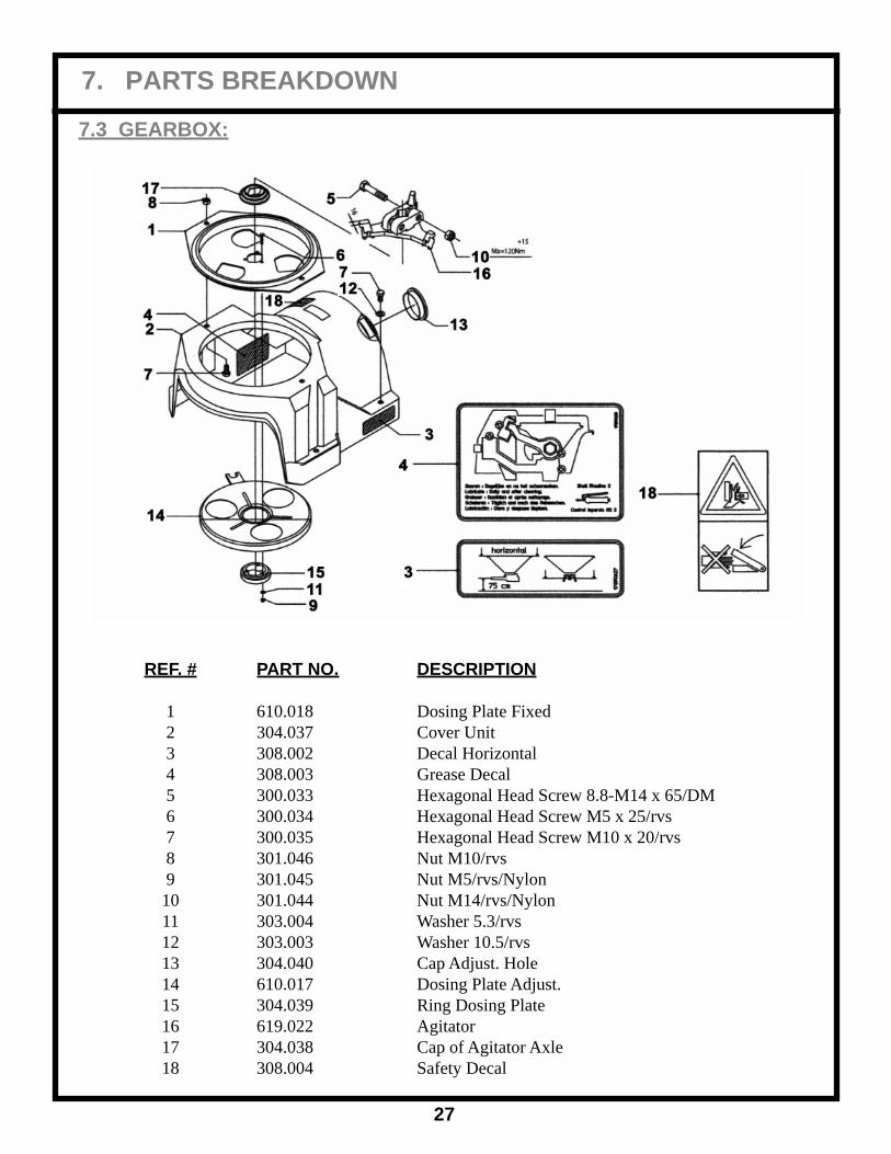
7.3 GEARBOX:
REF. # PART NO. DESCRIPTION
1 610.018 Dosing Plate Fixed 2 304.037 Cover Unit 3 308.002 Decal Horizontal 4 308.003 Grease Decal 5 300.033 Hexagonal Head Screw 8.8-M14 x 65/DM 6 300.034 Hexagonal Head Screw M5 x 25/rvs 7 300.035 Hexagonal Head Screw M10 x 20/rvs 8 301.046 Nut M10/rvs 9 301.045 Nut M5/rvs/Nylon 10 301.044 Nut M14/rvs/Nylon 11 303.004 Washer 5.3/rvs 12 303.003 Washer 10.5/rvs 13 304.040 Cap Adjust. Hole 14 610.017 Dosing Plate Adjust. 15 304.039 Ring Dosing Plate 16 619.022 Agitator 17 304.038 Cap of Agitator Axle 18 308.004 Safety Decal

7. PARTS BREAKDOWN
28
GEARBOX (CONTINUED):
REF. # PART NO. DESCRIPTION
19 332.005 Yoke Assembly 20 304.110 Flange Spout (long or short) 03 21 600.003 Spreading Basin 22 600.004 Center Axle 23 301.047 Special Nut Spout 24 300.061 Special Bolt Yoke Bearings 25 300.060 Bolt 10.9 - M12 x 65/DM 26 300.063 Bolt k100 - M12 x 40/DM 27 300.062 Bolt k100 - M12 x 50/DM 28 301.048 Nut k10/M12/DM 29 313.007 Circlip a25 x 1.2 30 303.002 Lockwasher 13/rvs 31 310.011 Bearing 6206-z 32 310.013 Bearing 6205-2lc 33 310.012 Bearing Yoke 34 306.009 Grease Nipple M8 x 1.25 35 303.001 Washer Bearing Yoke 36 304.041 Cap Bottom Bearing 37 299.006 Seal 38 299.005 Bearing Cap 39 299.007 Seal 40 321.002 Mainframe

7. PARTS BREAKDOWN
29
GEARBOX (CONTINUED):
REF. # PART NO. DESCRIPTION
41 304.045 Housing 42 303.032 Ring 43 624.002 Bearing Ring 44 304.042 Bearing Cap 45 304.043 Lock Cap Width Adjustment 46 300.064 Bolt PTO 10.9 - M10 x 48 47 599.002 Flywheel 48 304.044 Width Adjustment Ring 49 306.009 Grease Nipple M8 x 1.25 50 300.065 Bolt k100 - M8 x 25/DM 51 301.049 Nut M10/rvs/DM 52 305.009 Roll Pin 10 x 55 DM 53 310.015 Bearing 6009-2Z-C3 54 310.014 Bearing 6010-ZRS-C3 55 327.002 Rubber Buffer 56 617.006 Spring 57 303.036 Washer 58 323.014 Axle for PTO 59 303.037 Washer

7. PARTS BREAKDOWN
30
GEARBOX (CONTINUED):
REF. # PART NO. DESCRIPTION
60 619.026 Secondary Agitator (optional) 61 617.001 Agitator Spring 62 619.023 Agitator Crown 63 304.100 Spout Plastic Long 03 64 308.267 Pendulum Label 65 304.046 Band Grey 03 Long 66 305.007 Pin 3 x 40 67 304.047 Middle Plate (Long Spout) 68 618.016 Dosing Rod 69 618.017 Dosing Rod Nut 70 300.066 Bolt M6 x 25/rvs 71 301.051 Nut M6/rvs/Nylon 72 304.019 Protection Cover PTO
In order to fi x the protection cover PTO (72), use 3 cheese-headed screws 4.8 x 19 and 3 washers 5 x 20.

7. PARTS BREAKDOWN
31
7.4 OPTIONAL SPOUTS:
REF. # PART NO. DESCRIPTION SPREAD 73 304.101 Spout Plastic Short 13 to 26 Feet 74 304.105 Spout, Stainless Steel 6 to 33 Feet 75 304.102 Spout, Stainless Steel 3 to 14 Feet 77 304.103 Spout, Stainless Steel 6 to 13 Feet

7. PARTS BREAKDOWN
32
7.5 PDV500 / 600 HYDRAULIC SYSTEM - OPTIONAL:
REF. # QTY. PART NO. DESCRIPTION
HYDRAULIC CONTROL SYSTEM: 1 619.029 Hydraulic Opening System For PDV500/600 1 1 623.005 Hydraulic Cylinder 2 1 304.023 Hydraulic Tube 3 1 300.055 Hexagonal Head Screw 12 x 60 4 1 300.069 Hexagonal Head Screw 8 x 30 5 1 301.008 Self Locking Nut M12 6 1 301.001 Self Locking Nut M8 7 2 303.007 Washer 8 x 17 8 1 606.074 Connection Plate f/Hydraulic Opening System 9 1 325.012 Bushing 13 x 8 x 7 10 1 301.000 Nut M12
HYDRAULIC COMPLETE LEVER: 1 618.018 Complete Lever PDV500/600 1 1 304.009 Rubber Handle 2 1 635.008 Lever Extension 3 1 602.018 Tie Rod Lever w/Blade PDV400 Model 5 1 804.001 PVC Sheath 10 1 617.003 Spring for Lever 14 1 303.021 Washer 16 x 3 x 30 15 1 301.018 Self Locking Nut M16

7. PARTS BREAKDOWN
33
7.6 PDHV800 HYDRAULIC SYSTEM - OPTIONAL:
REF. # QTY. PART NO. DESCRIPTION
HYDRAULIC CONTROL SYSTEM: 1 619.030 Hydraulic Opening System For PDHV800 1 1 623.005 Hydraulic Cylinder 2 1 304.023 Hydraulic Tube 3 1 300.055 Hexagonal Head Screw 12 x 60 4 1 300.050 Hexagonal Head Screw 8 x 25 5 1 301.008 Self Locking Nut M12 6 1 301.001 Self Locking Nut M8 7 2 303.007 Washer 8 x 17 8 1 606.075 Connection Plate f/Hydraulic Opening System 9 1 325.012 Bushing 13 x 8 x 7 10 1 301.000 Nut M12
HYDRAULIC COMPLETE LEVER: 1 618.012 Complete Lever PDHV800 1 1 304.009 Rubber Handle 2 1 635.008 Lever Extension 3 1 602.019 Tie Rod Lever w/Blade 5 1 804.001 PVC Sheath 10 1 617.003 Spring for Lever 14 1 303.021 Washer 16 x 3 x 30 15 1 301.018 Self Locking Nut M16

34
8. LIMITED WARRANTY
GEARMORE, INC., warrants each new Gearmore product to be free from defects in material and workmanship for a period of twelve (12) months from date of purchase to the original purchaser. This warranty shall not apply to implements or parts that have been subject to misuse, negligence, accident, or that have been altered in any way.
Our obligation shall be limited to repairing or replacement of any part, provided that such part is returned within thirty (30) days from date of failure to Gearmore through the dealer from whom the purchase was made, transportation charges prepaid.
This warranty shall not be interpreted to render us liable for injury or damages of any kind or nature, direct, consequential or contingent, to person or property. This warranty does not extend to loss of crops, loss because of delay in harvesting or any other expenses, for any other reasons.
Gearmore in no way warranties engines, tires, or other trade accessories, since these items are warranted separately by these respective manufacturers.
Gearmore reserves the right to make improvements in design or changes in specifi cation at any time, without incurring any obligations to owners or units previously sold.
GEARMORE, INC.13477 Benson Ave.
Chino, CA 91710Always refer to and heed machine operating warning decals on machine.
The serial number of this product is stored in our computer database, thus submitting a warranty registration card is not required.
CUSTOMER INFORMATION
NAME: _______________________________________________
PURCHASED FROM: __________________________________
DATE OF PURCHASE: _________________________________
MODEL NUMBER: ____________________________________
SERIAL NUMBER: ____________________________________