penetration of hydrogen in distillate as a result of
TRANSCRIPT

PENETRATION OF HYDROGEN IN DISTILLATE AS A RESULT OF HERMETIC DISTURBANCE ON THE COOLING SYSTEM OF
THE STATOR WINDING ON TURBO-GENERATOR TYPE TVV-200-2A
M.Sc. TONI PASPALOVSKI
Thermo Power Plant Bitola, Electric Power Company of Macedonia Ul. Dimce Lahcanski 34/44, 7000 Bitola, FYRO Macedonia
tel. +389 47 206439, fax. +389 47 282295
Prof. DAMJAN HRISTOVSKI, Ph.D. Electro Technical Faculty – Skopje
Bul. Ilindenska 3/I/5, 1000 Skopje, FYRO Macedonia tel. +389 2 3099136, fax. +389 2 3161106
M.Sc. DRAGAN HRISTOVSKI
Department for Distribution and Supply of Electric Energy, Electric Power Company of Macedonia ul.Kozle 49a, 1000 Skopje, FYRO Macedonia
tel. +389 2 3149105, fax. +389 2 3161106
Abstract: - This paper describes hermetic disturbance on the cooling system of the stator winding cooled with distillate, resulting in penetration of the hydrogen in the distillate and with that making worse the cooling conditions. On the basis of the experience acquired in the diagnostics and prevention of such a faults in Thermo Power Plant Bitola, in the paper are presented some benefits which could help in making decisions, what should be done when such a defect occur the turbo-generator. Key-words: Turbo-generator (TG), stator, hydrogen, distillate, micro gap
1 Introduction On the turbo-generators type TVV 200-2A the stator winding is cooled directly with distillate which flows through the hollow elementary conductors of the stator winding, while the stator core and the rotor are cooled with hydrogen. Working pressure of the hydrogen is kept on higher value then the pressure of the distillate in order not to allowed wetting of the isolation if the tightness is damaged. In case of disturbance of the tightness, the hydrogen penetrates in the winding. With this disturbing the circulation of the distillate in some parallel branches of the cooling system and also endangering the stator winding because of overheating.
By this kind of defect, the generator must be put out of operation, defect to be diagnosed and repaired. The experience has shown that detecting the place of the defect is very difficult, and sometimes without success, especially if we speak
about micro gap. Namely, the micro gaps that allow penetration of the hydrogen in the winding for the time of operation, afterwards they become closed when the generator needs to be repaired. This happens because of cooling of the winding, and because of change of the pressure when the hydrogen is let out from the generator and the pressure of the distillate becomes higher then the pressure of the gas in the generator. After putting the generator into operation, the same micro gaps are opened.
2 Description of the distillate cooling system of the stator winding on TG type TVV-200-2A
On Fig.1 is shown principal scheme of the water cooling system on the stator winding of turbo-generator type TVV-200-2A [3].
Proceedings of the 5th WSEAS Int. Conf. on Power Systems and Electromagnetic Compatibility, Corfu, Greece, August 23-25, 2005 (pp340-346)

Wedge
Termoelement
izolation
Hollow conductor
Elementary conductor
Stator core
Fig. 1 Principal scheme of the cooling system of the stator winding Cooling of stator windings of the turbo-
generator is done by bringing up the distillate in the elementary hollow conductors of the bars on the stator winding by a closed scheme: pump - heat exchanger - filters - input (supply) collector of the turbo-generator - stator winding - output (main) collector of the turbo-generator - reservoir - pump. For circulation of the distillate through the stator winding are used two centrifugal pumps (1a and 1b on Fig.1) from which one is operational and the other is reserve. After the pump, the distillate enters in the heat exchanger (2a and 2b on Fig.1), where it is cooled to the necessary temperature. Further, the distillate enters through the filters for mechanical (3a and 3b on Fig.1) and magnetic cleaning (7 on Fig.1) into the supply ring collector for input into the stator winding. Inside the generator, the cooling system consists of input (supply) and output (main) collector and 60 basic cooling branches.
The bigger part of the cooling branches consists of two bars (one of them placed on the bottom of the gutter and the other in the upper bar from the gutter shifted for the shorted winding step), which are merged together with copper pipes into the head of the winding and with Teflon pipes for the supply and main collector. These connections are achieved with special screw connectors. The cooling
branches to which belong the bars of the beginnings and ends of the phase windings are longer, because they also include the connection bars and the generator outputs, so in this case the conditions of cooling are little unfavorable.
The bar of the winding consists of elementary conductors (42 peaces) from which every third is hollow (Fig. 2). In the active part of the winding, the elementary conductors reach transposition of 360o.
Fig. 2 Cross section of a gutter of the stator on turbogenerator type TVV-200-2A
OC
H2Gener at or
OC Q R
%H2
1a
1b2a 2b
3a
3b
456
7
8
910
6 11
12 13
111414
14 14
14
14
14
Proceedings of the 5th WSEAS Int. Conf. on Power Systems and Electromagnetic Compatibility, Corfu, Greece, August 23-25, 2005 (pp340-346)

Direct cooling of the stator winding is achieved with distillate which flows through hallow elementary conductors, meaning that the circulation of the water in the generator is carried out through 60 x 40 = 840 parallel branches.
In case of hermetic disturbance on the cooling system of the stator winding in the inner part of the generator, the hydrogen penetrates in the distillate, which partly is dissolved into the water and partly in a form of bubbles passes through the system. On some parts gas corks could be made, even it could come to complete blockage to some of the elementary conductors. Gas bubbles that will arrive in the collectors mainly are collected from the higher points, from where they come to the gas catcher (8 on Fig.1). The system for automatic gas analysis (9 on Fig.1), which observes the gas catcher, detects presence of hydrogen and in case the concentration of hydrogen is higher than 1% than the signalization is given. While the turbo-generator is in operation, the valves from the gas catcher must be opened all the time.
The distillate after the output of the generator is lead to the vacuum reservoir (10 on Fig.1) where it is dispersed on a grid in order the gas to be released from the distillate. The reservoir is constructed in a way for default stabile level to be kept, with a floating regulator and signalization for the limit levels. For support of the vacuum, it is placed ejector for technical water, and the reservoir is connected with the upper part of the condenser (12 on Fig1). Except for taking out the gases from the distillate, the reservoir is also used for supplement of the loss distillate (13 on Fig.1) while the system is in operation, and simultaneously it serves for supply of the water for intake from the pumps.
In the system continuously are followed following values: • Temperature on entrance and exit of the
generator with thermometer (11 on Fig.1) • Temperature on entrance and exit of the
generator with resistant thermometer with graduation 23 (6 on Fig.1)
• Flow of distillate through the stator winding (5 on Fig.1)
• Specific resistance of the distillate (4 on Fig.1)
• Control of concentration of hydrogen in gas, in the gas catcher (9 on Fig.1)
• Measurement of the pressures on the distillate with manometers
Having in view the possible places for penetration of the hydrogen, the following could be concluded:
- The biggest possibility of hermetic disturbance are the screw connections and the micro cracks on the welded connections
- Possible places of the hermetic disturbance are also the generator outputs
- Penetration of hydrogen directly in the bar is with low possibility and this could be practically neglected
- The possibility of cracking of Teflon pipe is also minimal and practically negligible The places with biggest possibility of
penetration of hydrogen in the distillate could be found on the beginning, in the middle and at the end of the cooling branches, and the number of possible places are 742 (480 welding places and 262 screw connections) [7].
3 Approach to a problem In case of penetration of hydrogen in the distillate, a part of the hydrogen, which could be found in the distillate in a form of bubbles, decreases the flow of the distillate in certain cooling branches and thus the cooling of this parts of the stator winding is decreased. This lead to increase of the temperature of the copper, and with this to the isolation also. If this temperature is above the permitted value, the isolation is getting worse, and in worst cases, the damage because of heating is so big that it comes to an electric breakdown [6].
With regards to the danger from disturbance of the cooling system on the stator winding, two cases should be taken into consideration: a) The hydrogen that penetrates in the system is
moving in form of gas bubbles together with the distillate without stopping or gas "pillows" are made, so they do not break the circulation of the distillate. This is the case when the hole, from which the hydrogen is passing, is with small geometrical dimensions (small quantity of hydrogen), and the speed of the distillate is relatively high (small dimensions of the gas bubbles).
b) The quantity of the hydrogen that penetrates in the distillate is so big, so in this case the normal cooling of the stator winding of the turbo-generator is disturbed.
4 Approximate determination of the place and the size of the defect
On Figure 3, it is presented one branch from the cooling system of the stator winding of the turbo-generator type TVV-200-2A.
Proceedings of the 5th WSEAS Int. Conf. on Power Systems and Electromagnetic Compatibility, Corfu, Greece, August 23-25, 2005 (pp340-346)

Fig.3 Scheme of the cooling system i.e. the movement of distillate through the stator winding
1- Pressure measurement of the distillate on entrance and exit from the generator
2 - Bushings for income and outcome of distillate from the generator
3 - Input (supply) and output (main) collector 4 - Highest point on the supply and on the main
collector 5 - Lower bar of the stator winding 6,8 - Output bars of the winding 7 - Generator output 9 - Upper bar of the stator winding 10- Gas catcher
pH2Ov, pH2Oi - Pressure of the distillate on entrance and exit from the generator
x - Distance of the place of the defect from the beginning of one parallel branch
l - Length of the cooling path of one parallel branch
pH2(x) - pressure of the hydrogen on the place of defect
pH2O(x) - pressure of the distillate on the place of defect
Fig. 4 Zoom of cross section of a defect (micro gap)
1 2 3
4
QH O2
PH Ov2
123
4
QH O2
PH Oi2
765 98
10
PH2(x)
lX
PH2O(x)
Ph2 generator
P’2 ν2
P2
P1H2
H O2
Fµ
νH2O
Fσ
ν2= 0
Proceedings of the 5th WSEAS Int. Conf. on Power Systems and Electromagnetic Compatibility, Corfu, Greece, August 23-25, 2005 (pp340-346)

2
22
'21 ν
ρρρξ ++=
ppp
221 )( HH pxpp ≈=
( )
OHOVH
OiHOVHOVHOH
plxp
pplxpxpp
22
22222 )(
∆−=
=−−≈=
2
22νξ
ρξ =
p
( ) ( )µσξρν ppp
lxp OH −−∆+∆
+= 21
2
( )µσρξν ppp
lxpSSq OHH −−∆+∆
+=⋅= 22
21
( ) ( )( ) l
pppp
xOH
⋅∆
−+∆−=
00
2
µσ
( ) ( )[ ]0021 222 OHOHH pp
lxppSq ∆−∆+∆−∆
+=
ρξ
( )µσ ppplxp OH −−∆=∆− 2
( )0212 ppSqH ∆−∆+
=ρξ
( )0212
ppqSS H
∆−∆==
+∗ ρ
ξ
On the place of a defect (micro gap) Fig.4 because of existing difference in the pressures between the hydrogen and the distillate, the gas will begin to flow [4]. If the difference in the pressures is small than Bernoulli's equation could be written:
(1) where: p2
’ - pressure of the gas on the exit of the gap In order the gas to penetrate in the liquid, the pressure p2
’ should be higher than p2 for value pσ, in order to overcome surface stress and the "sticking" force of the hydrogen on the walls of the channel. The flow of the distillate provokes an appearance of force of friction of the gas bubble, which "helps" for easily penetration of the gas into the water. The pressure corresponding to this force is marked with pµ. Than it could be written:
p2’ = p2 + pσ - pµ (2)
where: p2 – pressure of the distillate on the place of the
defect If the drop of pressure in the distillate is neglected on the path from 1 - 3, and with assumption that on the path from 3 - 9 the pressure drops linearly, it is obtained:
(3)
In the equation (1), pξ is drop of pressure due to the losses when the hydrogen passes through the gap
(4)
where: ξ - coefficient of losses dependent from the geometry of the gap, the roughness of the walls of the gap and some other factors From equations (1) and (4) it is obtained
(5)
where: ∆p = pH2 – pH2O
The quantity of the hydrogen that penetrate in the distillate is:
(6) where S is effective cross section of the gap. For
is obtained qH2 = 0 i.e.
(7)
where ∆p(0) is such a difference of the pressure between pH2 and pH2O, at which it stops the penetration of the hydrogen in the distillate. For easily calculation could be supposed that pσ - pµ ≈ const. In this case from (6) and (7) is obtained:
(8)
If ∆pH2 - ∆pH2O(0) ≈0 what is the case, if the flow of the distillate is not changing, then equation (8) could be simplified
(9)
From (9) could be determined
(10)
where S * in a certain meaning is a measure for the size of the defect
Proceedings of the 5th WSEAS Int. Conf. on Power Systems and Electromagnetic Compatibility, Corfu, Greece, August 23-25, 2005 (pp340-346)
0 ∆p−∆p ∆p(0)
qH2= 0
X = l
0 < X < l
X = 0
P pσ µ− =0
Pσ−pµ>0
S *1
Pσ−pµ>
0
Pσ−p
µ>0
Pσ−pµ>0
Pσ−pµ=
0
S1*
S *>S *2 1
S *1
S *1
S *1
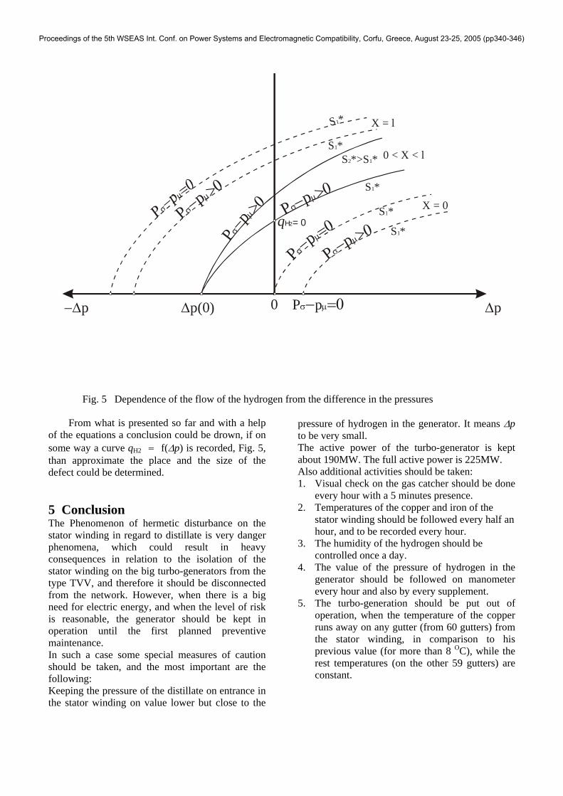
Fig. 5 Dependence of the flow of the hydrogen from the difference in the pressures
From what is presented so far and with a help of the equations a conclusion could be drown, if on some way a curve qH2 = f(∆p) is recorded, Fig. 5, than approximate the place and the size of the defect could be determined.
5 Conclusion The Phenomenon of hermetic disturbance on the stator winding in regard to distillate is very danger phenomena, which could result in heavy consequences in relation to the isolation of the stator winding on the big turbo-generators from the type TVV, and therefore it should be disconnected from the network. However, when there is a big need for electric energy, and when the level of risk is reasonable, the generator should be kept in operation until the first planned preventive maintenance. In such a case some special measures of caution should be taken, and the most important are the following: Keeping the pressure of the distillate on entrance in the stator winding on value lower but close to the
pressure of hydrogen in the generator. It means ∆p to be very small. The active power of the turbo-generator is kept about 190MW. The full active power is 225MW. Also additional activities should be taken: 1. Visual check on the gas catcher should be done
every hour with a 5 minutes presence. 2. Temperatures of the copper and iron of the
stator winding should be followed every half an hour, and to be recorded every hour.
3. The humidity of the hydrogen should be controlled once a day.
4. The value of the pressure of hydrogen in the generator should be followed on manometer every hour and also by every supplement.
5. The turbo-generation should be put out of operation, when the temperature of the copper runs away on any gutter (from 60 gutters) from the stator winding, in comparison to his previous value (for more than 8 OC), while the rest temperatures (on the other 59 gutters) are constant.
Proceedings of the 5th WSEAS Int. Conf. on Power Systems and Electromagnetic Compatibility, Corfu, Greece, August 23-25, 2005 (pp340-346)

References: [1] I.G.Balabanov, V.M. Chervanovski; "Control of the distillate in stator windings from
an electric machine cooled with hydrogen" "Power Plants" 1983/7 page 48÷50 Written in Russian
[2] I.D.Galicii, I.J.Dushar, V.V.Nikolaev, A.M.Timoshik; “Analyses of maintenance documentation of turbo-generators” "Power Plants" 1978/5 page 35÷38 Written in Russian
[3] Three phase synchronous turbo-generator type TVV-200-2AUZ and exciter type VGT-2700-500UZ – Technical description and instructions for operation OBS. 460. 247 TO -Moskva, 1995god; Written in Russian
[4] D. Hristovski; Testing of electrical machines, Electro Technical Faculty - Skopje 1996; Written in Macedonian
[5] G.M. Hutoreckii; M.I.Tokov; E.V.Tolvinkaja Turbo-generators designing – “Energoatomizdat” Leningrad 1987; Written in Russian
[6] T. Paspalovski, Power output increase possibilities for turbo-generators and particularly type TVV-200-2A, Master work, Electro Technical Faculty – Skopje 2003; Written in Macedonian
[7] S.I. Hazan, Energoatomizdat; Turbo-generators - Malfunctions and repair, “ - Moskva 1985; Written in Russian
[8] S.A. Motigina; Operation of electrical parts of thermal power plants, “ENERGIJA” - Moskva 1979; Written in Russian
Proceedings of the 5th WSEAS Int. Conf. on Power Systems and Electromagnetic Compatibility, Corfu, Greece, August 23-25, 2005 (pp340-346)