pentek ro-2550 4-stage reverse osmosis …® ro-2550 4-stage reverse osmosis water filtration system...
TRANSCRIPT

PENTEK® RO-2550 4-STAGE REVERSE OSMOSIS WATER FILTRATION SYSTEMINSTALLATION AND OPERATION MANUAL
©2014 Pentair Residential Filtration, LLC www.pentairaqua.com
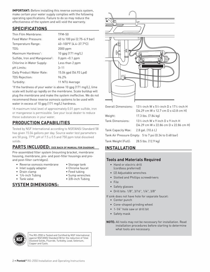
IMPORTANT: Before installing this reverse osmosis system, make certain your water supply complies with the following operating specifications. Failure to do so may reduce the effectiveness of the system and will void the warranty.
SPECIFICATIONSThin Film Membrane: TFM-50Feed Water Pressure: 40 to 100 psi (2.75–6.9 bar)Temperature Range: 40–100°F (4.4–37.7°C)TDS: 2000 ppmMaximum Hardness†: 10 gpg (171 mg/L)Sulfide, Iron and Manganese‡: 0 ppm <0.1 ppmChlorine in Water Supply: Less than 2 ppmpH Limits: 3–11Daily Product Water Rate: 15.04 gpd (56.93 Lpd)TDS Rejection: 96.2%Turbidity: 11 NTU Average†If the hardness of your water is above 10 gpg (171 mg/L), lime scale will build up rapidly on the membrane. Scale buildup will plug the membrane and make the system ineffective. We do not recommend these reverse osmosis systems to be used with water in excess of 10 gpg (171 mg/L) hardness.‡A maximum total level of approximately 0.01 ppm sulfide, iron or manganese is permissible. See your local dealer to reduce these substances in your water.
PRODUCTION CAPABILITIESTested by NSF International according to NSF/ANSI Standard 58 has given 15.04 gallons per day. Source water test parameters are 50 psig, 77°F, pH of 7.5 ± 0.5 and 750 ppm total dissolved solids.
PARTS INCLUDED: (SEE BACK OF MANUAL FOR DIAGRAM)
Pre-assembled filter system (mounting bracket, membrane housing, membrane, pre- and post-filter housings and pre- and post-filter cartridges).
• Reverseosmosismembrane •Storagetank• Inletsupplyadapter •Chromefaucet• Drainclamp •Feedtubing• 1/4-inchTubing •Sumpwrenches• Tankvalve •3/8-inchTubing
SYSTEM DIMENSIONS:
Overall Dimensions: 131⁄2-inch W x 51⁄2-inch D x 171⁄4-inch H (34.29cmWx12.7cmDx43.8cmH)Weight: 17.3lbs.(7.84kg)Tank Dimensions: 131⁄2-inch W x 9 inch D x 9 inch H (34.29cmWx22.86cmDx22.86cmH)TankCapacityMax: 2.8gal.(10.6L)TankAirPressureEmpty: 5to7psi(0.34to0.48bar)
TankWeight(Full): 28.5lbs.(12.9kg)
INSTALLATION
The RO-2550 is Tested and Certified by NSF International againstNSF/ANSIStandard58forthereductionofTotalDisolved Solids, Fluoride, Turbidity, Lead, Selenium, Copper and Cysts.
Tools and Materials Required• Hand or electric drill
(cordless preferred)• (2) Adjustable wrenches• Slotted and Phillips screwdrivers• File• Safety glasses• Drillbits:1/8",3/16",1/4",3/8"
If sink does not have hole for separate faucet:• Center punch• Cone-shaped grinding wheel• 1-1⁄4"holesawordrillbit• Safety mask
NOTE: All tools may not be necessary for installation. Read installation procedures before starting to determine what tools are necessary.
2•Pentek® RO-2550 Installation and Operating Instructions

GENERALWARNING: Do not use with water that is microbiologically
unsafe or of unknown quality without adequate disinfection before or after the system. Systems certified for cyst reduction* may be used on disinfected waters that may contain filterable cysts.
*NSF/ANSIStandard58certifiedtoreducecystssuchasCryptosporidium and Giardia by mechanical means.
CAUTION: Filter must be protected against freezing, which can cause cracking of the filter and water leakage.
CAUTION: Because of the product’s limited service life and to prevent costly repairs or possible water damage, we strongly recommend that the bottom of all plastic housings be replaced every five years for clear and ten years for opaque. If the bottom of your housing has been in use for longer than this period, it should be replaced immediately. Date the bottom of any new or replacement housing to indicate the next recommended replacement date.
NOTE:•Yourwatermustbewithinrequiredlimitsforsatisfactory
operation. If not, your membrane life may be shortened and your warranty will be voided (see Specifications on page 1).
•Thisreverseosmosissystemwillnotprotectagainstdisease-causing bacteria or remove naturally-occurring harmless bacteria.
•Installoncoldwaterlineonly.•Donotusewickingorsealertofitconnectionsintothecapof
the filter. Plumber tape is recommended. •Makecertainthatinstallationcomplieswithallstateand
local laws and regulations. •Thereplacementcartridgesandreverseosmosismembrane
included with this system have limited service lives. Changes in taste, odor, and color of the water being filtered indicate that the cartridge should be replaced (see Replacing the Pre- andPost-Filtersonpage8,andReplacingtheMembrane,onpage 9).
•Afterprolongedperiodsofnon-use(suchasduringavacation) it is recommended that the system be flushed for 5 minutes before it is used.
•Adrinkingwatercartridgemaycontaincarbonfines(veryfine black powder). After installation, flush the system for 5 minutes to remove the carbon fines before using the water.
•Itisrecommendedthatyourunthetapatleast20secondsprior to using water for drinking or cooking purposes.
•Thecontaminantsorothersubstancesremovedorreducedby this water treatment device are not necessarily present in your water.
RO MEMBRANE PRECAUTIONSCAUTION: Chlorine will destroy the TFM-50 membrane. If you
use the RO-2550 with a chlorinated or periodically-chlorinatedwatersupply,itisABSOLUTELYNECESSARYtouseacarbonpre-filter(includedwith the system). This carbon pre-filter should be changed at least every 3 months to avoid chlorine bypass. See Warranty for disclaimers and limitations that apply to the TFM-50 membrane.
HOW REVERSE OSMOSIS WORKS The RO-2550 Reverse Osmosis (RO) System uses a semi-permeable membrane to reduce dissolved salts and minerals, improving the taste and odor of your water. The RO membrane is made of layers of micron-thin film wound around a hollow center core. Water molecules can pass through the membrane, but dissolved salts and minerals are rejected. The RO-2550 Reverse Osmosis System features 4-stage filter action.Yourwatersupplyispre-filteredtoreducedirtandchlorine that may foul the membrane. The RO membrane separates this pre-filtered water into PRODUCT WATER and DRAIN or REJECT WATER. Incoming water pressure forces the product water through the membrane and into the storage tank. Dissolved solids and other contaminants cannot pass through the membrane and are sent to the drain as reject water. When you open the drinking water faucet, product water is drawn from the storage tank through an activated carbon post-filter, providing you with cleaner, great-tasting water. For each gallon of water produced, several gallons are discharged as reject water. The storage tank can hold up to 2.8gallons(10.6L)ofwateratatime,fordrinkingandcookingneeds. When used under the Specifications on page 1 of the manual, your Reverse Osmosis membranes should last 12-24 months.
BASIC INSTALLATION PROCEDURE GUIDELINES•Forstandard,under-sinkinstallationon3/8-inch(10mm)
steel, brass, or copper cold water line.•Pleasereadallinstructionsandprecautionsbeforeinstalling
and using your RO-2550.•Numbereddiagramscorrespondwithnumberedsteps.
PRECAUTIONS
•Readallinstallationandoperatinginstructionsbeforeinstalling and using your RO system.
•Numbereddiagramscorrespondwithnumberedsteps.1. Installing the Water Supply AdapterThe supply adapter fits 1/2-inch 14 NPS threads. If local codes permit, it may be used to connect the RO-2550 to the cold water supply line. If local codes do not permit the use of the supply adapter, alternate connectors can be obtained from your local plumbing wholesaler.Directions:(A) Turn off cold water inlet supply line. If cold water line does
not have a shut-off valve under the sink, you should install one.
(B) Turn on the cold water faucet and allow all water to drain from line.
(C) Disconnect cold water line from 1/2-inch 14 NPS threaded stub on bottom of main faucet.
(D) Using the nut that previously connected the cold water line to the faucet, screw the cold water line to the male supply adapter threads.
INSTALLATION CONTINUED . . .
NOTE:•Tomakesurenochlorineispresentinthewaterthatreaches
the membrane, you may want to use a chlorine test kit to check the brine/reject water that flows from the membrane to the drain. No chlorine should be detected.
•TheTFM-50membraneisresistanttonaturally-occurringbacteria.
Pentek® RO-2550 Installation and Operating Instructions•3

2. Selecting the Faucet LocationThe drinking water faucet should be positioned with function, convenience and appearance in mind. An adequate flat area is required to allow faucet base to rest securely. The faucet fits through a 11⁄4-inch hole. Most sinks have pre-drilled 11⁄2-inch or 13⁄8-inch diameter holes designed for spray hoses. The drinking water faucet may be installed using one of these holes, despite their larger size. If these pre-drilled holes cannot be used or are in an inconvenient location, it will be necessary to drill a 11⁄4-inch hole in the sink or through countertop next to the sink for the faucet. CAUTION: This procedure may generate dusts which can cause severe
irritation if inhaled or come in contact with the eyes. The use of safety glasses and safety mask for this procedure is recommended.
CAUTION: Do not attempt to drill through an all-porcelain or porcelain-coated sink. For applications on these types of sinks we recommend using the sprayer hole or mounting the faucet through the countertop.
CAUTION: When drilling through a countertop make sure the area below the drilled area is free of wiring and piping. Make certain that you have ample room to make the proper connections to the bottom of the faucet.
CAUTION: Do not drill through a countertop that is more than 1 inch thick.CAUTION: Do not attempt to drill through a tiled, marble, granite or similar
countertop. Consult a plumber or the countertop manufacturer for advice or assistance.
The following instructions apply to stainless steel sinks ONLY.(A) Line bottom of sink with newspaper to prevent shavings, parts or tools
from falling down the drain.
(B) Place masking tape over the area to be drilled to help prevent scratches if drill bit slips.
(C) Mark point with center punch. Use a 1/4-inch drill bit to drill a pilot hole through sink.
(D) Use a 11⁄4-inch hole saw to enlarge hole. Smooth rough edges with a file.
3. Mounting the Faucet(A) Loosen stem-nut on faucet, remove metal slotted disc (if attached).(B) Attachlargediameter3/8-inchdraintubetobarbfittingatthefaucetbase.
This tube should be long enough to reach the drain clamp in Step 4.(C) Attach small diameter 1/4-inch drain tube to other barb fitting at faucet
base. This tube should be long enough to reach right side of the RO Assembly.
(D) Slide chrome plate and black rubber washer onto faucet by threading both drain tubes through the holes on the plate and washer.
(E) Slide white extension onto long threaded section of faucet. Open end of extension should come in contact with base of faucet.
(F) Apply 3-5 wraps of plumber tape to faucet stem. Screw quick connector onto end of threads.
(G)Wetendof3/8"tube.Pushintobottomofconnector.Tuggentlytobesureconnection is complete.
NOTE: To remove the tube, push on the fittings' collar and pull the tube out.(H) Holding the faucet, feed the three tubes through the hole in the sink.
Position the faucet handle at a desired location(I) Center the faucet and slip slotted disc between the white extension and the
bottom of the counter or sink. Tighten the stem nut with a wrench until it is tight.
(J) Firmly insert goose-neck spout into faucet base.
4. Installing the Drain ClampNOTE: If you have a single-basin sink with a disposal unit, call Technical
Support for options.NOTE: Before installing the drain clamp, check the drainpipes under the sink
D
1
A
B
C
D
DC
1⁄4”
11⁄4”A
B
C
D
Pilot Hole
Mounting Hole
11⁄4"
1/4"
2
3
Counter Top
B
C
D
E
G
F
I
A
4•Pentek® RO-2550 Installation and Operating Instructions

for corrosion. Corroded pipes should be replaced before continuing with installation.
(A) Attach the drain clamp to a vertical section of the drainpipe, about 6 inches above the trap. Make sure the opening on the drain clamp is facing towards the drinking water faucet (see diagram on previous page).
(B) Using the fitting hole of the drain clamp as a guide, drill a 1/4-inch hole through one side of the drainpipe.
(C)Removethedrainclampfromthedrainpipeandenlargetheholewitha3/8-inch drill bit. Use a file to remove rough edges from the drilled hole.
(D) Make sure the black rubber gasket is adhered to the inside of the drain clamp and place the drain clamp assembly over the drilled hole. Look through the hole and position the clamp so that the center of the clamp hole is slightly higher (about 1/16-inch) than the center of the drilled hole. Tighten the clamp securely.
(E) Screw the plastic compression nut onto the drain clamp until hand-tight.
5. Connecting the Faucet to the DrainCAUTION: This is a gravity drain line. Any loops, kinks or sharp bends must be
eliminated before proceeding. Failure to create a straight line to the drain may result in reject water leaking through the air gap in the faucet onto the countertop and below the faucet.
(A)Alignthelargerreject(3/8-inch)tubingfromthefaucetwiththecompressionnut on the drain clamp. Create as straight and smooth a path as possible with the tubing. Do not kink tube. Cut the tubing squarely below the nut and remove the internal and external burrs.
(B) Loosen the compression nut two complete turns. Insert the tubing into the nut until it stops. Tighten with fingers, then tighten 1 to 2 turns with a wrench.
6. Installation of Mounting Screws(A) If system is being installed under the kitchen sink, locate it on back or right
wall. Make sure to allow ample space for installation. To change the filter cartridges, a minimum of 1-1⁄2 inches of clearance is required underneath the filter housings. A minimum of 2 inches of clearance from the left side of the unit is also required or 5 inches from the left bracket mounting screw hole.
(B) Install mounting screws at least 15 inches from cabinet floor and 71⁄2-inches apart. Leave a 5/16-inch space between the head of the screw and the wall to slip bracket onto screws. NOTE: Each connection fitting on the RO Assembly has a plug that must be
removed before inserting tubing. Push in on the collar and pull the plug out.
7. Connecting the Faucet to the System(A) Locate the reject tubing (reject water line) from the drinking water faucet. This
tubeisthesmallerofthetwo.Placeamarkonthetubing5/8-inchfromtheend. Moisten the end of the tubing with water and insert tubing into the quick-connect fitting on the flow restrictor found on the right side of system behind the membrane.
If tubing is not firmly connected, leaking will occur. It is important for the tubing to be inserted all the way until the mark is flush with the outer edge of the quick-connect insert. NOTE: Tubing may be quickly and easily removed from the fitting if necessary by
pressing the collar around the fitting then pulling the tubing with your other hand.
(B) The faucet tube from the bottom of the threaded metal tube is inserted into the post filter. The fitting is at the top left of the RO System. Push the free end of the tubing into the quick connect fitting.
INSTALLATION CONTINUED . . . 8. Connecting the Storage Tank to the SystemCAUTION: Whentankisfull,itweighsapproximately28.5lbs.(12.9kg)Provide
ample support under the tank.
4A
B C
6"
D
E
5 A
B
3/8"Tube
65"(min.) 71⁄2"
15"(min.)
11⁄2"(min.)
2"(min.)
7
A
BPort Reference
Pentek® RO-2550 Installation and Operating Instructions•5

(A) To prevent leaks, apply 3 or more wraps of plumber tape to threads on tank. Thread the tank valve onto the top of the tank opening. Turn tank so handle is in line with tubing.
CAUTION: The tank/valve connection will leak if not properly sealed. plumber tape will normally seal the threaded connection.
(B) Locatethe1/4-inchtubing.Placeamarkonthetubing5/8-inchfromeachend. Moisten one end of the tubing with water and insert with a twisting motionintotheportofthetankvalveuntilthe5/8-inchmarkisflushwiththequick connect fitting. Then locate the tank near the system's installation area.
(C) Cut the tubing to correct length. Install free end of tubing into white quick-connect fitting on the post filter tee on the right side. Do not cut tubing.
(D) Place entire system over mounting screws on wall and slide down.CAUTION: Make certain system is firmly attached to wall to prevent it from falling
and possibly becoming damaged. NOTE: Use caution not to bend or pinch the tubing behind the system while
attaching to mounting screws.
9. Connecting the Supply Adapter and Inlet Filter(A) Locate remaining length of 1/4-inch plastic tubing. (B) Push into quick connect fitting on the right side of system.(C) Cut the tube to a length that will allow connection to the cold water supply
fitting. Ensure the tubing does not kink. Push the tube into the fitting.
10. Installing the Membrane(A) Remove tube attached to membrane housing by pressing in the white collar
around the fitting while pulling the tubing with your other hand.(B) Hold the membrane housing with one hand and turn the cap (wrench
provided) with other hand to remove. To make it easier to hold the membrane housing, you may want to remove the post-filter.
(C) With clean hands (sanitary gloves preferred), remove the membrane from the plastic bag. HANDLE WITH CARE.
CAUTION: Do not unwrap the tape around the membrane, as it is part of the membrane. Do not squeeze membrane.
(D) With the double O-ring side first, push membrane into housing until it stops. About1/8-inchofthemembrane’splasticcorewillstickoutbeyondthehousing.
(E) Use clean silicone grease (pack is included with the system) to lubricate both O-rings and the brine seal. Hand-tighten membrane housing cap until you feel resistance, then tighten an additional 1/2 turn. Do not over-tighten.
(F) Reinsert the tube by pushing it into the quick connect fitting.
INSTALLATION CONTINUED . . . 11. Faucet Operation(A) For controlled water flow, push the handle down.
B
Port Reference
9 A
C1/4"Tube
5/8" 16 mm
5/8" 16 mm
10
A
A
D
E
Port Reference
Port Reference
C
8 A
B
1/4"Tube
Apply plumber
tape5/8"
6•Pentek® RO-2550 Installation and Operating Instructions
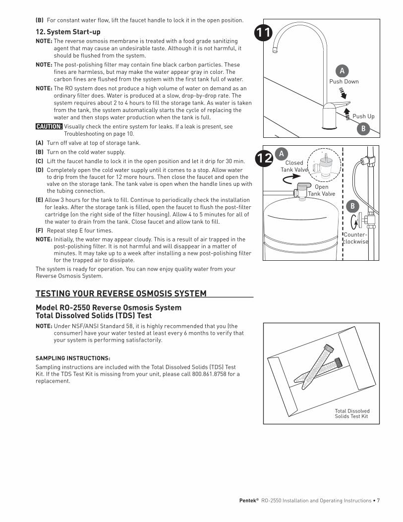
(B) For constant water flow, lift the faucet handle to lock it in the open position.
12. System Start-upNOTE: The reverse osmosis membrane is treated with a food grade sanitizing
agent that may cause an undesirable taste. Although it is not harmful, it should be flushed from the system.
NOTE: The post-polishing filter may contain fine black carbon particles. These fines are harmless, but may make the water appear gray in color. The carbon fines are flushed from the system with the first tank full of water.
NOTE: The RO system does not produce a high volume of water on demand as an ordinary filter does. Water is produced at a slow, drop-by-drop rate. The system requires about 2 to 4 hours to fill the storage tank. As water is taken from the tank, the system automatically starts the cycle of replacing the water and then stops water production when the tank is full.
CAUTION: Visually check the entire system for leaks. If a leak is present, see Troubleshooting on page 10.
(A) Turn off valve at top of storage tank.(B) Turn on the cold water supply.(C) Lift the faucet handle to lock it in the open position and let it drip for 30 min. (D) Completely open the cold water supply until it comes to a stop. Allow water
to drip from the faucet for 12 more hours. Then close the faucet and open the valve on the storage tank. The tank valve is open when the handle lines up with the tubing connection.
(E) Allow 3 hours for the tank to fill. Continue to periodically check the installation for leaks. After the storage tank is filled, open the faucet to flush the post-filter cartridge (on the right side of the filter housing). Allow 4 to 5 minutes for all of the water to drain from the tank. Close faucet and allow tank to fill.
(F) Repeat step E four times.NOTE: Initially, the water may appear cloudy. This is a result of air trapped in the
post-polishing filter. It is not harmful and will disappear in a matter of minutes. It may take up to a week after installing a new post-polishing filter for the trapped air to dissipate.
Thesystemisreadyforoperation.YoucannowenjoyqualitywaterfromyourReverse Osmosis System.
TESTING YOUR REVERSE OSMOSIS SYSTEMModel RO-2550 Reverse Osmosis System Total Dissolved Solids (TDS) TestNOTE:UnderNSF/ANSIStandard58,itishighlyrecommendedthatyou(the
consumer) have your water tested at least every 6 months to verify that your system is performing satisfactorily.
SAMPLING INSTRUCTIONS:Sampling instructions are included with the Total Dissolved Solids (TDS) Test Kit.IftheTDSTestKitismissingfromyourunit,pleasecall800.861.8758forareplacement.
11
Push Down
Push Up
B
A
12 Closed Tank Valve
B
A
Counter-clockwise
Open Tank Valve
Total Dissolved Solids Test Kit
Pentek® RO-2550 Installation and Operating Instructions•7
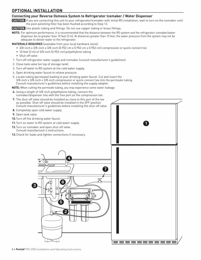
OPTIONAL INSTALLATIONConnecting your Reverse Osmosis System to Refrigerator Icemaker / Water DispenserCAUTION: If you are connecting this unit to your refrigerator/icemaker with initial RO installation, wait to turn on the icemaker until
the post-polishing filter has been flushed according to Step 12.CAUTION: Use plastic tubing and fittings. Do not use copper tubing or brass fittings. NOTE: For optimum performance, it is recommended that the distance between the RO system and the refrigerator icemaker/water
dispenser be no greater than 10 feet (3 m). At distances greater than 10 feet, the water pressure from the system may not be adequate to deliver water to the refrigerator.
MATERIALS REQUIRED (available from your local hardware store): •3/8-inchx3/8-inchx3/8-inch(0.952cmx0.952cmx0.952cm)compressionorquick-connecttee •10feet(3m)of3/8-inch(0.952cm)polyethylenetubing • Shut-offvalve 1. Turn off refrigerator water supply and icemaker (consult manufacturer’s guidelines). 2. Close tank valve (on top of storage tank). 3. Turn off water to RO system at the cold water supply. 4. Open drinking water faucet to relieve pressure. 5. Locate tubing (permeate) leading to your drinking water faucet. Cut and insert the
3/8-inch x 3/8-inch x 3/8-inch compression or quick-connect tee into the permeate tubing. Consult manufacturer’s guidelines before installing the supply adapter.
NOTE: When cutting the permeate tubing, you may experience some water leakage. 6. Using a length of 3/8-inch polyethylene tubing, connect the
icemaker/dispenser line with the free port on the compression tee. 7. The shut-off valve should be installed as close to this port of the tee
as possible. Shut-off valve should be installed in the OFF position Consult manufacturer’s guidelines before installing the shut-off valve.
8. Completely open cold water supply. 9. Open tank valve. 10. Turn off the drinking water faucet.11. Turn on water to RO system at cold water supply.12. Turn on icemaker and open shut-off valve. Consult manufacturer’s instructions.13. Check for leaks and tighten connections if necessary.
1
2
7
6
5
4
3
8•Pentek® RO-2550 Installation and Operating Instructions

1st Stage Pre-Filter and 2nd Stage Pre-Filter Cartridges: The cartridge should be replaced every six months. If your water contains a high amount of sediment, it may be necessary to change the 1st stage cartridge more frequently. If your water contains a high amount of chlorine, it may be necessary to change the 2nd stage pre-filter more often.1. Turn off incoming water supply and valve on the storage
tank. Place a tray under the system to catch any water that spills during removal of the filter housings.
2. Open faucet to release pressure.3. Unscrew bottom of filter housings from caps. Use the filter
wrench. Discard used cartridges.4. Remove black rubber O-rings from grooves in housings.
Wipe grooves and O-rings clean; set O-rings aside. 5. Rinse out housings and fill each 1/3 with water. Add 2
tablespoons of bleach and scrub with non-abrasive brush or sponge. Rinse thoroughly.
6. Lubricate each O-ring with a coating of clean silicone grease. With two fingers, press each O-ring securely into groove below the threads of the appropriate housing.
CAUTION: The rubber O-ring provides the water-tight seal between the cap and the bottom of the housing. It is important that the O-ring be properly seated in the groove below the threads of the housing or a water leak could occur.
7. Insert cartridges in the bottom of
the housings. Make sure cartridge slips over standpipe in the bottom of the housing.
NOTE: Be sure to install cartridges in proper housings (see diagram below).
8. Screw bottoms of housings back onto caps securely; do not over-tighten. Turn on cold water supply. Check for leaks. Continue to check periodically to make sure no leaks develop.
4th Stage Post-Filter Cartridge: post-filter should be replaced every twelve months.1. Turn off incoming water supply and valve on the storage
tank. Place a tray under the system to catch any water that spills during removal of the filter housings.
2. Open faucet to release pressure.3. Remove filter from bracket and discard.4. Remove tubes from fittings by pressing in collar around the fitting while pulling the tubing out with your other hand. NOTE: If quick connect fittings need to be installed, tape
threads of fittings with 3 wraps of plumber tape and attach to filter.
CAUTION: Ensure the tape is not touching O-ring on the fitting or a leak may occur.
NOTE: The filter has an arrow on it showing the direction of flow. The tee fitting connects to the inlet side of the filter and the elbow fitting attaches to the outlet side.
NOTE: Hand tighten fittings, then tighten with wrench 1/4 turn.5. Attach 4th stage filter to bracket with the tee fitting on the
right hand side.6. Attach tubes to fittings by pushing in until the tube stops.
Check to see if tube is in place by trying to gently pull tube out.
REPLACING THE PRE-FILTER AND POST-FILTER CARTRIDGES
1/4"FeedTube
1/4"FaucetDrain Tube3/8"DrainTube
GS-10RO (4th Stage Post-Filter)
TFM-50 Membrane (3rd Stage Pre-
Filter)
P5 (1st Stage Pre-Filter)
EPM10 (2nd Stage Post-Filter)
1/4"StorageTank Permeate Tube
3/8"FaucetPermeate Tube
Pentek® RO-2550 Installation and Operating Instructions•9

About the Reverse Osmosis MembraneWhen used under operating conditions specified on page 1 of the manual, your reverse osmosis membrane should last at leastoneyear.Youshouldreplacethemembraneafter18to24months. Replace it sooner if you notice a return of unpleasant tastes or odors or a noticeable decline in water production. The precise life span of your system's membrane will depend on the quality of the water entering the system and the frequency with which you use it. Frequent system use prevents the filtered salts and minerals from building up on the membrane as scale. The more water the system is required to produce, thelongerthemembranewilllast.Youmaywishtofindavariety of uses for your system in order to prolong the life of the membrane. During extended periods of non-use (such as during a vacation), remove the membrane from the membrane housing and place it in a sealed plastic bag. Store membrane in refrigerator for future use. DO NOT FREEZE. NOTE: If system stands for more than 2 to 3 days without being
used, the storage tank should be emptied.
Replacing the Membrane and Sanitizing the System and FiltersNOTE: It is recommended that you sanitize the system each
time you change the membrane. It is not necessary to sanitize the system when changing only the pre-filters or post-filter.
NOTE: When installing a new membrane, it is recommended that you replace the pre-filter and post-filter cartridges as well.
Removing the Membrane and Filters 1. Turn off the cold water supply. Allow five minutes for system
to depressurize. Place a tray under the system to catch any water that spills during removal of the filter housings.
2. Open drinking water faucet to drain tank. When tank is drained, close faucet.
3. Hold the membrane housing with one hand and remove the cap with the other hand.
CAUTION: Do not disconnect tubing from membrane cap. 4. To remove the RO membrane, grasp membrane tube with
pliers and pull. Discard old membrane. Screw cap back onto membrane housing. DO NOT install new membrane.
5. Unscrew filter housings from caps and discard used cartridges.
6. Remove black rubber O-rings from grooves in housings. Wipe grooves and O-rings clean; set O-rings aside.
Sanitizing the System 7. Rinse out bottom of housings and fill each 1/3 with water.
Add 2 tablespoons of household bleach to each housing and scrub cap, bottom of housings, and membrane housing with non-abrasive sponge or cloth. Rinse thoroughly.
8. Lubricate O-rings with a coating of clean silicone grease. With two fingers, press each O-ring securely into groove below the threads of the appropriate housing.
CAUTION: The rubber O-ring provides the water-tight seal between the cap and the bottom of the housing. It is
important that the O-ring be properly seated in the groove below the threads of the housing or a water leak could occur.
9. Screw bottom of housing onto caps WITHOUT inserting prefilters and hand-tighten. Do not over-tighten.
10. Open the cold water supply and let the system run for 2 to 3 minutes to carry the bleach solution throughout the system.
11. Close the cold water supply and turn on the drinking water faucet. Let the faucet run for about 30 seconds before turning off.
12. Let the entire system stand for 30 minutes to sanitize. 13. After 30 minutes, turn on the drinking water faucet to allow
the bleach water to run out (about 3 to 5 minutes). 14. Unscrew bottom of housings. Discard bleach water and rinse.
Replacing the Membrane and Filter CartridgesTo replace the filters, see Replacing the Pre-Filters and Post-Filteronpage8.To replace the membrane, see Step 10: Installing the MembraneNOTE: After installing new membrane and cartridges, allow
system to run for 3 hours to fill tank. Check for leaks every hour. As pressure builds in tank, leaks may occur that did not exist directly after installation.
When the membrane and cartridges have been changed, follow the system start-up procedure in Step 12: System Start-up.
SUGGESTED LIST PRICE REPLACEMENT CARTRIDGES P5SedimentFilter:$3.89 EPM10 Carbon Filter: $6.50 50 GPD Element: $36.40 GAC Post Filter: $21.61
REPLACING THE 3RD STAGE REVERSE OSMOSIS MEMBRANE
10•Pentek® RO-2550 Installation and Operating Instructions
Leaks between bottom of housing and cap1. Ensure sump is tightly screwed to cap. If it still leaks close
the cold water supply and tank valves. 2. Clean black rubber O-ring and lubricate with clean silicone
grease. With two fingers, insert O-ring in groove below threads of housing and press into place. Tighten housing back onto cap.
3. Open the cold water supply and tank valve. If leaks persist, call Technical Support.
Leaks on tank valve assembly1. Open drinking water faucet to drain storage tank. Let
drinking water faucet run until it drips. Turn off cold water supply.
2. Push in on white collar of tank valve fitting and pull out tubing. Unscrew the tank valve from the storage tank. Rewrap threads on top of the tank with plumber tape. Screw tank valve back onto tank. Trim 1/2-inch from end of tubing andreinsert5/8-inchintotankvalvefitting.
3. Open the cold water supply and shut off the reverse osmosis faucet. Let the system pressurize for several hours and check for leaks. Check again after tank is fully pressurized.
Leaks on quick-connect fittings1. Close the cold water supply and tank valve.2. Depress plastic collar and pull out tubing.3.Cutoff1inchoftubingandplaceamark5/8-inchfromend
of tubing. Tubing should be cut squarely. The internal and external burrs should be removed.
4.Pushtubing5/8-inchintofitting.5. Open the cold water supply and tank valve. If leaks persist,
call Technical Support.
No flow or slow flow from the brine (drain) lineLess than 1½ cups per minuteNOTE: Before checking brine (or reject) flow, make sure the
system is producing water by turning off the valve on the storage tank and opening the faucet. Water should drip from faucet.
1. Examine the P5 and EPM10 pre-filters. If clogged, replace (seeReplacingthePre-FilterandPost-Filteronpage8)andrecheck the brine (or reject) flow rate.
2. If the pre-filters are not at fault, the brine (or drain) flow controller is probably clogged. Call Technical Support.
High TDS in Product WaterIf high levels of TDS (Total Dissolved Solids) are detected in your product water (approximately 30% or greater of what is measured in your tap water, as determined with a conductivity meter or by the supplied TDS Test Kit), the RO membrane may need to be replaced, or the brine (or drain) flow control tubing may be clogged. See your dealer or plumber to check product water TDS.
Reduced productionSlow or no product water flow usually indicates either a clogged pre-filter or an exhausted membrane. First, replace the pre-filters. If the production rate is not improved, replace membrane.
Gradual return of taste and odorGradual return of unpleasant taste and odor over a period of time may indicate that your filter cartridges and/or RO membrane need to be replaced. See Replacing the Pre-Filters onpage8 and Replacing the Reverse Osmosis Membrane”on page 9.
Sudden return of taste and odorIf shortly after complete servicing noticeable taste and odors return contact Technical Support.
No water pressure from the drinking water faucet or low volume in storage tank1. Close the cold water supply to system.2. Lift storage tank to see if it is empty. If not, open the drinking
water faucet to empty water from tank.NOTE: It may be necessary to pump a small amount of air into
the tank with a bicycle pump to remove all the water from the tank.
3. When tank is empty, use a pressure gauge to check tank pressure. An empty tank should contain 5 to 7 psi pressure. Increase or decrease the air pressure in the tank accordingly.
4. Open cold water supply. Let system run for 3 hours to fill tank, then check system performance. If performance has not improved, call Technical Support.
TROUBLESHOOTING GUIDE
Pentek® RO-2550 Installation and Operating Instructions•11

Important Notice: Read this performance data and compare the capabilities of this system with your actual water treatment needs. It is recommended that before installing a water treatment system, you have your water supply tested to determine your actual water treatment needs.ThissystemhasbeentestedaccordingtoNSF/ANSI58forthereduction of the substances listed below. The concentration for the indicated substances in water entering the system was reduced to a concentration less than or equal to the permissible limit for waterleavingthesystem,asspecifiedinNSF/ANSI58.NOTE: Substances reduced are not necessarily in your water.
Filter must be maintained according to manufacturer’s instructions, including replacement of filter cartridges.
Thetestedefficiencyratingforthissystemis7.68%.Efficiencyrating means the percentage of the influent water to the system that is available to the user as reverse osmosis treated water under operating conditions that approximate typical daily usage. The tested recovery rating is 20.1%. Recovery rating means the percentage of the influent water to the membrane portion of the system that is available to the user as reverse osmosis treated water when the system is operated without a storage tank or when the storage tank is bypassed
Model RO-2550
Substance
Average Influent
Concentration
Maximum Permissible
Product Water
ConcentrationReduction
RequirementsAverage
ReductionStandard58
Barium 10.0 mg/L ± 10% 2.0 mg/L 98.3%
Cadmium 0.03 mg/L ± 10% 0.005 mg/L 98.7%
Chromium (Hexavalent)
0.3 mg/L ± 10% 0.1 mg/L 91.2%
Chromium (Trivalent)
0.3 mg/L ± 10% 0.1 mg/L 94.8%
Copper 3.0 mg/L ± 10% 1.3 mg/L 98.9%
Fluoride 8.0mg/L±10% 1.5 mg/L 95.6%
Lead 0.15 mg/L ± 10% 0.010 mg/L 98.7%
Radium 226/228 25 pCi/L ± 10% 5 pCi/L 80.0%
Selenium 0.10 mg/L ± 10% 0.05 mg/L 96.0%
Turbidity 11 NTU ± 1 NTU 0.5 NTU 99.0%
Total Dissolved Solids
750 mg/L ± 40 mg/L 187mg/L 96.2%
Cysts* Minimum 50,000/mL 99.95% 99.99%
PERFORMANCE DATA
*NSF/ANSIStandard58certifiedtoreducecystssuchasCryptosporidiumandGiardia by mechanical means.
EPA#082989-CHN-001
12•Pentek® RO-2550 Installation and Operating Instructions

1 244796 Drain Clamp2 244797 Inlet Supply Adapter3 244959 Faucet4 153049 Housing5 244794 1/4-inch Tubing6 244795 3/8-inchTubing7 244783 TankValve(1/4"NPTx1/4"QC)8 244833 Storage Tank9 155014-43 1st Stage Sediment Pre-filter (P5)10 155634-43 2nd Stage Pre-filter (EPM1O)
PARTS GUIDE11 555583-43 3rd Stage RO Membrane TFM-5012 555574-43 4th Stage Post-filter GS-10RO-B with
fittings13 150539 SW-1 Wrench14 150640 RO Housing Wrench15 143495 Silicone16 244835 FaucetAdaptor7/16-24UNSx3/8"QC17 244787 Valve Auto Shut-off18 161080 Membrane Housing19 150538 TDS Test Kit* 244837 Flow Restrictor, TFM-50 (*Not Shown)
For replacement parts, contact your nearest Water Filter dealer or call 800.279.9404
1 4
32
7
8
5
6
11109 12
1413
15
1617
1819
Pentek® RO-2550 Installation and Operating Instructions•13

Buyer Seller Date
14•Pentek® RO-2550 Installation and Operating Instructions

Pentek® RO-2550 Installation and Operating Instructions•15

FILTRATION & PROCESS5730 NORTH GLEN PARK ROAD, MILWAUKEE, WI 53209 P:262.238.4400| WWW.PENTAIRAQUA.COM|CUSTOMERCARE:800.279.9404| [email protected]
All Pentair trademarks and logos are owned by Pentair, Inc. or its affiliates. All other registered and unregistered trademarks and logos are the property of their respective owners. Because we are continuously improving our products and services, Pentair reserves the right to change specifications without prior notice. Pentair is an equal opportunity employer.SH247113 REV C AP14 ©2014 Pentair Residential Filtration, LLC All Rights Reserved.
For Pentair® Product Warranties visit:Pentair® para las gasantías de los productos visite:
Pour Pentair® garanties produit visitez le site: } www.pentairaqua.com/pro