people soft complete guide
TRANSCRIPT

Enterprise PeopleTools 8.48PeopleBook: PeopleSoft ApplicationDesigner
June 2006

Enterprise PeopleTools 8.48 PeopleBook: PeopleSoft Application DesignerSKU PT848APD-B 0606Copyright © 1988-2006, Oracle. All rights reserved.
The Programs (which include both the software and documentation) contain proprietary information; they areprovided under a license agreement containing restrictions on use and disclosure and are also protected by copyright,patent, and other intellectual and industrial property laws. Reverse engineering, disassembly, or decompilation of thePrograms, except to the extent required to obtain interoperability with other independently created software or asspecified by law, is prohibited.
The information contained in this document is subject to change without notice. If you find any problems in thedocumentation, please report them to us in writing. This document is not warranted to be error-free. Except as maybe expressly permitted in your license agreement for these Programs, no part of these Programsmay be reproduced ortransmitted in any form or by anymeans, electronic or mechanical, for any purpose.If the Programs are delivered to the United States Government or anyone licensing or using the Programs on behalf ofthe United States Government, the following notice is applicable:
U.S. GOVERNMENT RIGHTSPrograms, software, databases, and related documentation and technical data delivered to U.S. Governmentcustomers are “commercial computer software” or “commercial technical data” pursuant to the applicable FederalAcquisition Regulation and agency-specific supplemental regulations. As such, use, duplication, disclosure,modification, and adaptation of the Programs, including documentation and technical data, shall be subject tothe licensing restrictions set forth in the applicable Oracle license agreement, and, to the extent applicable, theadditional rights set forth in FAR 52.227-19, Commercial Computer Software--Restricted Rights (June 1987).Oracle Corporation, 500 Oracle Parkway, Redwood City, CA 94065.The Programs are not intended for use in any nuclear, aviation, mass transit, medical, or other inherently dangerousapplications. It shall be the licensee’s responsibility to take all appropriate fail-safe, backup, redundancy and othermeasures to ensure the safe use of such applications if the Programs are used for such purposes, and we disclaimliability for any damages caused by such use of the Programs.The Programsmay provide links toWeb sites and access to content, products, and services from third parties.Oracle is not responsible for the availability of, or any content provided on, third-partyWeb sites. You bear all risksassociated with the use of such content. If you choose to purchase any products or services from a third party, therelationship is directly between you and the third party. Oracle is not responsible for: (a) the quality of third-partyproducts or services; or (b) fulfilling any of the terms of the agreement with the third party, including delivery ofproducts or services and warranty obligations related to purchased products or services. Oracle is not responsible forany loss or damage of any sort that youmay incur from dealing with any third party.Oracle, JD Edwards, PeopleSoft, and Siebel are registered trademarks of Oracle Corporation and/or its affiliates.Other namesmay be trademarks of their respective owners.Open Source DisclosureOracle takes no responsibility for its use or distribution of any open source or shareware software or documentationand disclaims any and all liability or damages resulting from use of said software or documentation. The followingopen source software may be used in Oracle’s PeopleSoft products and the following disclaimers are provided.Apache Software FoundationThis product includes software developed by the Apache Software Foundation (http://www.apache.org/). Copyright© 2000-2003. The Apache Software Foundation. All rights reserved. Licensed under the Apache License, Version2.0 (the “License”); youmay not use this file except in compliance with the License. Youmay obtain a copy of theLicense at http://www.apache.org/licenses/LICENSE-2.0.Unless required by applicable law or agreed to in writing, software distributed under the License is distributed on an“AS IS” BASIS,WITHOUTWARRANTIESORCONDITIONSOFANYKIND, either express or implied. See theLicense for the specific language governing permissions and limitations under the License.OpenSSLCopyright © 1998-2005 The OpenSSL Project. All rights reserved.

This product includes software developed by the OpenSSL Project for use in the OpenSSL Toolkit(http://www.openssl.org/).THIS SOFTWARE IS PROVIDEDBYTHEOpenSSL PROJECT “AS IS” ANDANYEXPRESSEDORIMPLIEDWARRANTIES, INCLUDING, BUTNOTLIMITEDTO, THE IMPLIEDWARRANTIESOFMERCHANTABILITYANDFITNESS FORAPARTICULAR PURPOSEAREDISCLAIMED. INNOEVENTSHALLTHEOpenSSL PROJECTOR ITSCONTRIBUTORSBELIABLE FORANYDIRECT, INDIRECT,INCIDENTAL, SPECIAL, EXEMPLARY, ORCONSEQUENTIALDAMAGES (INCLUDING, BUTNOTLIMITEDTO, PROCUREMENTOF SUBSTITUTEGOODSORSERVICES; LOSSOFUSE, DATA, ORPROFITS; ORBUSINESS INTERRUPTION)HOWEVERCAUSEDANDONANYTHEORYOFLIABILITY,WHETHER INCONTRACT, STRICT LIABILITY, OR TORT (INCLUDINGNEGLIGENCEOROTHERWISE)ARISING INANYWAYOUTOFTHEUSEOFTHIS SOFTWARE, EVEN IFADVISEDOFTHE POSSIBILITYOF SUCHDAMAGE.Loki LibraryCopyright © 2001 byAndrei Alexandrescu. This code accompanies the book: Alexandrescu, Andrei. “Modern C++Design: Generic Programming and Design Patterns Applied”. Copyright © 2001Addison-Wesley. Permission touse, copy, modify, distribute and sell this software for any purpose is hereby granted without fee, provided that theabove copyright notice appear in all copies and that both that copyright notice and this permission notice appear insupporting documentation.Helma ProjectCopyright © 1999-2004 Helma Project. All rights reserved. THIS SOFTWARE IS PROVIDED “AS IS”ANDANYEXPRESSEDOR IMPLIEDWARRANTIES, INCLUDING, BUTNOTLIMITEDTO, THEIMPLIEDWARRANTIESOFMERCHANTABILITYANDFITNESS FORAPARTICULARPURPOSEAREDISCLAIMED. INNOEVENT SHALL THEHELMAPROJECTOR ITSCONTRIBUTORSBE LIABLE FORANYDIRECT, INDIRECT, INCIDENTAL, SPECIAL, EXEMPLARY, ORCONSEQUENTIALDAMAGES(INCLUDING, BUTNOTLIMITEDTO, PROCUREMENTOF SUBSTITUTEGOODSOR SERVICES;LOSSOFUSE, DATA, OR PROFITS; ORBUSINESS INTERRUPTION) HOWEVERCAUSEDANDONANYTHEORYOFLIABILITY,WHETHER INCONTRACT, STRICT LIABILITY, OR TORT (INCLUDINGNEGLIGENCEOROTHERWISE) ARISING INANYWAYOUTOF THEUSEOF THIS SOFTWARE, EVEN IFADVISEDOFTHE POSSIBILITYOF SUCHDAMAGE.Helma includes third party software released under different specific license terms. See the licenses directory in theHelma distribution for a list of these license.SarissaCopyright © 2004Manos Batsis.This library is free software; you can redistribute it and/or modify it under the terms of the GNULesser GeneralPublic License as published by the Free Software Foundation; either version 2.1 of the License, or (at your option)any later version.This library is distributed in the hope that it will be useful, butWITHOUTANYWARRANTY; without even theimplied warranty ofMERCHANTABILITY or FITNESS FORAPARTICULARPURPOSE. See the GNULesserGeneral Public License for more details.You should have received a copy of the GNULesser General Public License along with this library; if not, write tothe Free Software Foundation, Inc., 59 Temple Place, Suite 330, Boston,MA 02111-1307 USA.ICUICU License - ICU 1.8.1 and later COPYRIGHTANDPERMISSIONNOTICECopyright © 1995-2003International BusinessMachines Corporation and others. All rights reserved.

Permission is hereby granted, free of charge, to any person obtaining a copy of this software and associateddocumentation files (the “Software”), to deal in the Software without restriction, including without limitation therights to use, copy, modify, merge, publish, distribute, and/or sell copies of the Software, and to permit personsto whom the Software is furnished to do so, provided that the above copyright notice(s) and this permissionnotice appear in all copies of the Software and that both the above copyright notice(s) and this permission noticeappear in supporting documentation. THE SOFTWARE IS PROVIDED “AS IS,”WITHOUTWARRANTYOFANYKIND, EXPRESSOR IMPLIED, INCLUDINGBUTNOTLIMITEDTOTHEWARRANTIESOFMERCHANTABILITY, FITNESS FORAPARTICULAR PURPOSEANDNONINFRINGEMENTOFTHIRDPARTYRIGHTS. INNOEVENT SHALL THECOPYRIGHTHOLDERORHOLDERS INCLUDED IN THISNOTICEBELIABLE FORANYCLAIM, ORANYSPECIAL INDIRECTORCONSEQUENTIALDAMAGES,ORANYDAMAGESWHATSOEVERRESULTING FROMLOSSOFUSE, DATAORPROFITS,WHETHER INANACTIONOFCONTRACT, NEGLIGENCEOROTHERTORTIOUSACTION, ARISINGOUTOFOR INCONNECTIONWITHTHEUSEOR PERFORMANCEOF THIS SOFTWARE. Except as contained in this notice,the name of a copyright holder shall not be used in advertising or otherwise to promote the sale, use or other dealingsin this Software without prior written authorization of the copyright holder.All trademarks and registered trademarks mentioned herein are the property of their respective owners.Sun’s JAXB Implementation – JDSDK 1.5 relaxngDatatype.jar 1.0 LicenseCopyright © 2001, Thai Open Source Software Center Ltd, SunMicrosystems. All rights reserved.THIS SOFTWARE IS PROVIDEDBYTHECOPYRIGHTHOLDERSANDCONTRIBUTORS “ASIS” ANDANYEXPRESSOR IMPLIEDWARRANTIES, INCLUDING, BUTNOTLIMITEDTO, THEIMPLIEDWARRANTIESOFMERCHANTABILITYANDFITNESS FORAPARTICULARPURPOSEAREDISCLAIMED. INNOEVENT SHALLTHEREGENTSORCONTRIBUTORSBELIABLE FORANYDIRECT, INDIRECT, INCIDENTAL, SPECIAL, EXEMPLARY, ORCONSEQUENTIALDAMAGES(INCLUDING, BUTNOTLIMITEDTO, PROCUREMENTOF SUBSTITUTEGOODSOR SERVICES;LOSSOFUSE, DATA, OR PROFITS; ORBUSINESS INTERRUPTION) HOWEVERCAUSEDANDONANYTHEORYOF LIABILITY,WHETHER INCONTRACT, STRICT LIABILITY, ORTORT (INCLUDINGNEGLIGENCEOROTHERWISE) ARISING INANYWAYOUTOF THEUSEOF THIS SOFTWARE, EVEN IFADVISEDOFTHE POSSIBILITYOF SUCHDAMAGE.W3C IPR SOFTWARENOTICECopyright © 2000WorldWideWeb Consortium, (Massachusetts Institute of Technology, Institut National deRecherche en Informatique et en Automatique, Keio University). All Rights Reserved.Note: The original version of theW3C Software Copyright Notice and License could be found athttp://www.w3.org/Consortium/Legal/copyright-software-19980720.THIS SOFTWAREANDDOCUMENTATION IS PROVIDED “AS IS,” ANDCOPYRIGHTHOLDERSMAKENOREPRESENTATIONSORWARRANTIES, EXPRESSOR IMPLIED, INCLUDINGBUTNOTLIMITEDTO,WARRANTIESOFMERCHANTABILITYOR FITNESS FORANYPARTICULAR PURPOSEORTHATTHEUSEOFTHE SOFTWAREORDOCUMENTATIONWILLNOT INFRINGEANYTHIRD PARTYPATENTS,COPYRIGHTS, TRADEMARKSOROTHERRIGHTS. COPYRIGHTHOLDERSWILLNOTBELIABLE FORANYDIRECT, INDIRECT, SPECIALORCONSEQUENTIALDAMAGESARISINGOUTOFANYUSEOFTHE SOFTWAREORDOCUMENTATION.

Contents
General PrefaceAbout This PeopleBook ..... . . . . . . . . . . . . . . . . . . . . . . . . . . . . . . . . . . . . . . . . . . . . . . . . . . . . . . . . . . . . . . . . . . . . . . . . . . . . . . .xxvPeopleSoft Enterprise Application Prerequisites.. . . . . . . . . . . . . . . . . . . . . . . . . . . . . . . . . . . . . . . . . . . . . . . . . . . . . . . . . . . . . . . . .xxvApplication Fundamentals.. . . . . . . . . . . . . . . . . . . . . . . . . . . . . . . . . . . . . . . . . . . . . . . . . . . . . . . . . . . . . . . . . . . . . . . . . . . . . . . . . . . . . . . . . . .xxvDocumentation Updates and Printed Documentation.. . . . . . . . . . . . . . . . . . . . . . . . . . . . . . . . . . . . . . . . . . . . . . . . . . . . . . . . . .xxvi
Obtaining Documentation Updates.. . . . . . . . . . . . . . . . . . . . . . . . . . . . . . . . . . . . . . . . . . . . . . . . . . . . . . . . . . . . . . . . . . . . . .. . . . . .xxviDownloading and Ordering Printed Documentation.. . . . . . . . . . . . . . . . . . . . . . . . . . . . . . . . . . . . . . . . . . . . . . . . . . .. . . . . .xxvi
Additional Resources.. . . . . . . . . . . . . . . . . . . . . . . . . . . . . . . . . . . . . . . . . . . . . . . . . . . . . . . . . . . . . . . . . . . . . . . . . . . . . . . . . . . . . . . . . . . . . . .xxviiTypographical Conventions and Visual Cues.. . . . . . . . . . . . . . . . . . . . . . . . . . . . . . . . . . . . . . . . . . . . . . . . . . . . . . . . . . . . . . . . . . .xxviii
Typographical Conventions.. . . . . . . . . . . . . . . . . . . . . . . . . . . . . . . . . . . . . . . . . . . . . . . . . . . . . . . . . . . . . . . . . . . . . . . . . . . . . .. . . . .xxviiiVisual Cues.. . . . . . . . . . . . . . . . . . . . . . . . . . . . . . . . . . . . . . . . . . . . . . . . . . . . . . . . . . . . . . . . . . . . . . . . . . . . . . . . . . . . . . . . . . . . . . . . .. . . . . .xxixCountry, Region, and Industry Identifiers.. . . . . . . . . . . . . . . . . . . . . . . . . . . . . . . . . . . . . . . . . . . . . . . . . . . . . . . . . . . . . . .. . . . . .xxixCurrency Codes.. . . . . . . . . . . . . . . . . . . . . . . . . . . . . . . . . . . . . . . . . . . . . . . . . . . . . . . . . . . . . . . . . . . . . . . . . . . . . . . . . . . . . . . . . . . .. . . . . . .xxx
Comments and Suggestions.. . . . . . . . . . . . . . . . . . . . . . . . . . . . . . . . . . . . . . . . . . . . . . . . . . . . . . . . . . . . . . . . . . . . . . . . . . . . . . . . . . . . . . . .xxxCommon Elements Used in PeopleBooks.. . . . . . . . . . . . . . . . . . . . . . . . . . . . . . . . . . . . . . . . . . . . . . . . . . . . . . . . . . . . . . . . . . . . . . . .xxx
PrefacePeopleSoft Application Designer Preface.... . . . . . . . . . . . . . . . . .. . . . . . . . . . . . . . . . . . .. . . . . . . . . . . . . . . . . . .xxxiiiPeopleSoft Application Designer.. . . . . . . . . . . . . . . . . . . . . . . . . . . . . . . . . . . . . . . . . . . . . . . . . . . . . . . . . . . . . . . . . . . . . . . . . . . . . . . . .xxxiii
Part 1Getting Started with PeopleSoft Application Designer
Chapter 1Getting Started with PeopleSoft Application Designer..... . . . . . . . . . . . . . . . . . . . . . . . . . . . . . . . . . . . . . . . . . . . .3PeopleSoft Application Designer Overview.. . . . . . . . . . . . . . . . . . . . . . . . . . . . . . . . . . . . . . . . . . . . . . . . . . . . . . . . . . . . . . . . . . . . . . . . . .3PeopleSoft Application Designer Implementation.. . . . . . . . . . . . . . . . . . . . . . . . . . . . . . . . . . . . . . . . . . . . . . . . . . . . . . . . . . . . . . . . . . .3
Installation-Level Steps.. . . . . . . . . . . . . . . . . . . . . . . . . . . . . . . . . . . . . . . . . . . . . . . . . . . . . . . . . . . . . . . . . . . . . . . . . . . . . . . . . . .. . . . . . . . . .3Main Application Development Steps.. . . . . . . . . . . . . . . . . . . . . . . . . . . . . . . . . . . . . . . . . . . . . . . . . . . . . . . . . . . . . . . . . . .. . . . . . . . . .4Other Sources of Information.. . . . . . . . . . . . . . . . . . . . . . . . . . . . . . . . . . . . . . . . . . . . . . . . . . . . . . . . . . . . . . . . . . . . . . . . . . . .. . . . . . . . . .5
Copyright © 1988-2006, Oracle. All rights reserved. v

Contents
Part 2Developing and Customizing PeopleSoft Applications
Chapter 2Using PeopleSoft Application Designer... . . . . . . . . . . . . . . . . . . . . . . . . . . . . . . . . . . . . . . . . . . . . . . . . . . . . . . . . . . . . . . . .9Understanding PeopleSoft Application Designer.. . . . . . . . . . . . . . . . . . . . . . . . . . . . . . . . . . . . . . . . . . . . . . . . . . . . . . . . . . . . . . . . . . . .9Using PeopleSoft Application Designer. . . . . . . . . . . . . . . . . . . . . . . . . . . . . . . . . . . . . . . . . . . . . . . . . . . . . . . . . . . . . . . . . . . . . . . . . . . . . . .9
Understanding the Eight Steps of Application Development.. . . . . . . . . . . . . . . . . . . . . . . . . . . . . . . . . . . . . . . . .. . . . . . . . . .9Starting PeopleSoft Application Designer. . . . . . . . . . . . . . . . . . . . . . . . . . . . . . . . . . . . . . . . . . . . . . . . . . . . . . . . . . . . . . .. . . . . . . .11Using the PeopleSoft Application Designer Window Components.. . . . . . . . . . . . . . . . . . . . . . . . . . . . . . . . . .. . . . . . . .13Setting PeopleTools Options.. . . . . . . . . . . . . . . . . . . . . . . . . . . . . . . . . . . . . . . . . . . . . . . . . . . . . . . . . . . . . . . . . . . . . . . . . . . . .. . . . . . . .20
Working with PeopleCode... . . . . . . . . . . . . . . . . . . . . . . . . . . . . . . . . . . . . . . . . . . . . . . . . . . . . . . . . . . . . . . . . . . . . . . . . . . . . . . . . . . . . . . . . . .21Using the Development Editors.. . . . . . . . . . . . . . . . . . . . . . . . . . . . . . . . . . . . . . . . . . . . . . . . . . . . . . . . . . . . . . . . . . . . . . . . . .. . . . . . . .22
Working with Definitions.. . . . . . . . . . . . . . . . . . . . . . . . . . . . . . . . . . . . . . . . . . . . . . . . . . . . . . . . . . . . . . . . . . . . . . . . . . . . . . . . . . . . . . . . . . . . . .24Understanding Definitions.. . . . . . . . . . . . . . . . . . . . . . . . . . . . . . . . . . . . . . . . . . . . . . . . . . . . . . . . . . . . . . . . . . . . . . . . . . . . . . . .. . . . . . . .24Opening Definitions.. . . . . . . . . . . . . . . . . . . . . . . . . . . . . . . . . . . . . . . . . . . . . . . . . . . . . . . . . . . . . . . . . . . . . . . . . . . . . . . . . . . . . . .. . . . . . . .26Viewing Definitions.. . . . . . . . . . . . . . . . . . . . . . . . . . . . . . . . . . . . . . . . . . . . . . . . . . . . . . . . . . . . . . . . . . . . . . . . . . . . . . . . . . . . . . . .. . . . . . . .27Viewing and Editing Definition Properties.. . . . . . . . . . . . . . . . . . . . . . . . . . . . . . . . . . . . . . . . . . . . . . . . . . . . . . . . . . . . . .. . . . . . . .27Creating Definitions.. . . . . . . . . . . . . . . . . . . . . . . . . . . . . . . . . . . . . . . . . . . . . . . . . . . . . . . . . . . . . . . . . . . . . . . . . . . . . . . . . . . . . . .. . . . . . . .28Saving Definitions.. . . . . . . . . . . . . . . . . . . . . . . . . . . . . . . . . . . . . . . . . . . . . . . . . . . . . . . . . . . . . . . . . . . . . . . . . . . . . . . . . . . . . . . . .. . . . . . . .29Closing Definitions... . . . . . . . . . . . . . . . . . . . . . . . . . . . . . . . . . . . . . . . . . . . . . . . . . . . . . . . . . . . . . . . . . . . . . . . . . . . . . . . . . . . . . . .. . . . . . . .29Renaming Definitions.. . . . . . . . . . . . . . . . . . . . . . . . . . . . . . . . . . . . . . . . . . . . . . . . . . . . . . . . . . . . . . . . . . . . . . . . . . . . . . . . . . . . .. . . . . . . .29Deleting Definitions.. . . . . . . . . . . . . . . . . . . . . . . . . . . . . . . . . . . . . . . . . . . . . . . . . . . . . . . . . . . . . . . . . . . . . . . . . . . . . . . . . . . . . . . .. . . . . . . .31Finding Definitions.. . . . . . . . . . . . . . . . . . . . . . . . . . . . . . . . . . . . . . . . . . . . . . . . . . . . . . . . . . . . . . . . . . . . . . . . . . . . . . . . . . . . . . . . .. . . . . . . .32Using the Multiple Document Interface.. . . . . . . . . . . . . . . . . . . . . . . . . . . . . . . . . . . . . . . . . . . . . . . . . . . . . . . . . . . . . . . . .. . . . . . . .34Using Drag-and-Drop.. . . . . . . . . . . . . . . . . . . . . . . . . . . . . . . . . . . . . . . . . . . . . . . . . . . . . . . . . . . . . . . . . . . . . . . . . . . . . . . . . . . . .. . . . . . . .34Using Dynamic Toolbars and Menus.. . . . . . . . . . . . . . . . . . . . . . . . . . . . . . . . . . . . . . . . . . . . . . . . . . . . . . . . . . . . . . . . . . . .. . . . . . . .35Using Pop-up Menus.. . . . . . . . . . . . . . . . . . . . . . . . . . . . . . . . . . . . . . . . . . . . . . . . . . . . . . . . . . . . . . . . . . . . . . . . . . . . . . . . . . . . . .. . . . . . . .35Configuring the Environment.. . . . . . . . . . . . . . . . . . . . . . . . . . . . . . . . . . . . . . . . . . . . . . . . . . . . . . . . . . . . . . . . . . . . . . . . . . . . .. . . . . . . .36Working with Generated Files.. . . . . . . . . . . . . . . . . . . . . . . . . . . . . . . . . . . . . . . . . . . . . . . . . . . . . . . . . . . . . . . . . . . . . . . . . . . .. . . . . . . .38
Using Miscellaneous Definitions.. . . . . . . . . . . . . . . . . . . . . . . . . . . . . . . . . . . . . . . . . . . . . . . . . . . . . . . . . . . . . . . . . . . . . . . . . . . . . . . . . . . . .38Using Spell Check.. . . . . . . . . . . . . . . . . . . . . . . . . . . . . . . . . . . . . . . . . . . . . . . . . . . . . . . . . . . . . . . . . . . . . . . . . . . . . . . . . . . . . . . . . . . . . . . . . . . . .40
Understanding Spell Check.. . . . . . . . . . . . . . . . . . . . . . . . . . . . . . . . . . . . . . . . . . . . . . . . . . . . . . . . . . . . . . . . . . . . . . . . . . . . . .. . . . . . . .40Enabling Spell Check.. . . . . . . . . . . . . . . . . . . . . . . . . . . . . . . . . . . . . . . . . . . . . . . . . . . . . . . . . . . . . . . . . . . . . . . . . . . . . . . . . . . . .. . . . . . . .43Configuring Browser Options.. . . . . . . . . . . . . . . . . . . . . . . . . . . . . . . . . . . . . . . . . . . . . . . . . . . . . . . . . . . . . . . . . . . . . . . . . . . .. . . . . . . .44
Building and Maintaining Data.. . . . . . . . . . . . . . . . . . . . . . . . . . . . . . . . . . . . . . . . . . . . . . . . . . . . . . . . . . . . . . . . . . . . . . . . . . . . . . . . . . . . . . .45Data Building and Maintenance.. . . . . . . . . . . . . . . . . . . . . . . . . . . . . . . . . . . . . . . . . . . . . . . . . . . . . . . . . . . . . . . . . . . . . . . . .. . . . . . . .45Creating SQL Tables.. . . . . . . . . . . . . . . . . . . . . . . . . . . . . . . . . . . . . . . . . . . . . . . . . . . . . . . . . . . . . . . . . . . . . . . . . . . . . . . . . . . . . .. . . . . . . .45
vi Copyright © 1988-2006, Oracle. All rights reserved.

Contents
Chapter 3Working With Projects... . . .. . . . . . . . . . . . . . . . . . . . . . . . .. . . . . . . . . . . . . . . . . . . . . . . .. . . . . . . . . . . . . . . . . . . . . . . . . . . . . . . .47Understanding Projects.. . . . . . . . . . . . . . . . . . . . . . . . . . . . . . . . . . . . . . . . . . . . . . . . . . . . . . . . . . . . . . . . . . . . . . . . . . . . . . . . . . . . . . . . . . . . . . .47Viewing Projects.. . . . . . . . . . . . . . . . . . . . . . . . . . . . . . . . . . . . . . . . . . . . . . . . . . . . . . . . . . . . . . . . . . . . . . . . . . . . . . . . . . . . . . . . . . . . . . . . . . . . . . .48
Accessing Definitions for a Project. . . . . . . . . . . . . . . . . . . . . . . . . . . . . . . . . . . . . . . . . . . . . . . . . . . . . . . . . . . . . . . . . . . . . . .. . . . . . . .48Using the Upgrade View... . . . . . . . . . . . . . . . . . . . . . . . . . . . . . . . . . . . . . . . . . . . . . . . . . . . . . . . . . . . . . . . . . . . . . . . . . . . . . . . .. . . . . . . .49
Creating and Saving Projects.. . . . . . . . . . . . . . . . . . . . . . . . . . . . . . . . . . . . . . . . . . . . . . . . . . . . . . . . . . . . . . . . . . . . . . . . . . . . . . . . . . . . . . . .49Creating a New Project. . . . . . . . . . . . . . . . . . . . . . . . . . . . . . . . . . . . . . . . . . . . . . . . . . . . . . . . . . . . . . . . . . . . . . . . . . . . . . . . . . . .. . . . . . . .50Saving a Project. . . . . . . . . . . . . . . . . . . . . . . . . . . . . . . . . . . . . . . . . . . . . . . . . . . . . . . . . . . . . . . . . . . . . . . . . . . . . . . . . . . . . . . . . . . .. . . . . . . .50
Setting Project Properties.. . . . . . . . . . . . . . . . . . . . . . . . . . . . . . . . . . . . . . . . . . . . . . . . . . . . . . . . . . . . . . . . . . . . . . . . . . . . . . . . . . . . . . . . . . . .50Inserting Definitions Into a Project. . . . . . . . . . . . . . . . . . . . . . . . . . . . . . . . . . . . . . . . . . . . . . . . . . . . . . . . . . . . . . . . . . . . . . . . . . . . . . . . . . .51Removing Definitions From a Project. . . . . . . . . . . . . . . . . . . . . . . . . . . . . . . . . . . . . . . . . . . . . . . . . . . . . . . . . . . . . . . . . . . . . . . . . . . . . . . .53Merging Projects.. . . . . . . . . . . . . . . . . . . . . . . . . . . . . . . . . . . . . . . . . . . . . . . . . . . . . . . . . . . . . . . . . . . . . . . . . . . . . . . . . . . . . . . . . . . . . . . . . . . . . . .53Using Change Projects.. . . . . . . . . . . . . . . . . . . . . . . . . . . . . . . . . . . . . . . . . . . . . . . . . . . . . . . . . . . . . . . . . . . . . . . . . . . . . . . . . . . . . . . . . . . . . . .54Setting Project Options.. . . . . . . . . . . . . . . . . . . . . . . . . . . . . . . . . . . . . . . . . . . . . . . . . . . . . . . . . . . . . . . . . . . . . . . . . . . . . . . . . . . . . . . . . . . . . . .55Validating Projects... . . . . . . . . . . . . . . . . . . . . . . . . . . . . . . . . . . . . . . . . . . . . . . . . . . . . . . . . . . . . . . . . . . . . . . . . . . . . . . . . . . . . . . . . . . . . . . . . . . .56Setting System IDs.. . . . . . . . . . . . . . . . . . . . . . . . . . . . . . . . . . . . . . . . . . . . . . . . . . . . . . . . . . . . . . . . . . . . . . . . . . . . . . . . . . . . . . . . . . . . . . . . . . . .57
Chapter 4Creating Field Definitions.... .. . . . . . . . . . . . . . . . . .. . . . . . . . . . . . . . . . .. . . . . . . . . . . . . . . . . .. . . . . . . . . . . . . . . . . . . . . . . . .59Understanding Field Definitions.. . . . . . . . . . . . . . . . . . . . . . . . . . . . . . . . . . . . . . . . . . . . . . . . . . . . . . . . . . . . . . . . . . . . . . . . . . . . . . . . . . . . .59Creating New Field Definitions.. . . . . . . . . . . . . . . . . . . . . . . . . . . . . . . . . . . . . . . . . . . . . . . . . . . . . . . . . . . . . . . . . . . . . . . . . . . . . . . . . . . . . . .59
Creating a New Field Definition.. . . . . . . . . . . . . . . . . . . . . . . . . . . . . . . . . . . . . . . . . . . . . . . . . . . . . . . . . . . . . . . . . . . . . . . . . .. . . . . . . .60Specifying Attributes for a New Field Definition. . . . . . . . . . . . . . . . . . . . . . . . . . . . . . . . . . . . . . . . . . . . . . . . . . . . . . . .. . . . . . . .61Specifying Character Field Attributes.. . . . . . . . . . . . . . . . . . . . . . . . . . . . . . . . . . . . . . . . . . . . . . . . . . . . . . . . . . . . . . . . . . .. . . . . . . .62Specifying Long Character Field Attributes.. . . . . . . . . . . . . . . . . . . . . . . . . . . . . . . . . . . . . . . . . . . . . . . . . . . . . . . . . . . .. . . . . . . .64Specifying Number Field Attributes. . . . . . . . . . . . . . . . . . . . . . . . . . . . . . . . . . . . . . . . . . . . . . . . . . . . . . . . . . . . . . . . . . . . . .. . . . . . . .64Specifying Date Field Attributes. . . . . . . . . . . . . . . . . . . . . . . . . . . . . . . . . . . . . . . . . . . . . . . . . . . . . . . . . . . . . . . . . . . . . . . . . .. . . . . . . .66Specifying Time Field Attributes.. . . . . . . . . . . . . . . . . . . . . . . . . . . . . . . . . . . . . . . . . . . . . . . . . . . . . . . . . . . . . . . . . . . . . . . . .. . . . . . . .66Specifying DateTime Field Attributes. . . . . . . . . . . . . . . . . . . . . . . . . . . . . . . . . . . . . . . . . . . . . . . . . . . . . . . . . . . . . . . . . . . .. . . . . . . .66Specifying Image Field Attributes.. . . . . . . . . . . . . . . . . . . . . . . . . . . . . . . . . . . . . . . . . . . . . . . . . . . . . . . . . . . . . . . . . . . . . . .. . . . . . . .67Specifying ImageReference Field Attributes.. . . . . . . . . . . . . . . . . . . . . . . . . . . . . . . . . . . . . . . . . . . . . . . . . . . . . . . . . . .. . . . . . . .67Working With Additional Oracle Data Type Mappings.. . . . . . . . . . . . . . . . . . . . . . . . . . . . . . . . . . . . . . . . . . . . . . . .. . . . . . . .67Working With Additional Microsoft SQL Server 2005 Data Type Mappings. . . . . . . . . . . . . . . . . . . . . . . .. . . . . . . .68
Using Multiple Labels.. . . . . . . . . . . . . . . . . . . . . . . . . . . . . . . . . . . . . . . . . . . . . . . . . . . . . . . . . . . . . . . . . . . . . . . . . . . . . . . . . . . . . . . . . . . . . . . . .69Understanding Multiple Labels.. . . . . . . . . . . . . . . . . . . . . . . . . . . . . . . . . . . . . . . . . . . . . . . . . . . . . . . . . . . . . . . . . . . . . . . . . . .. . . . . . . .69Adding a New Label. . . . . . . . . . . . . . . . . . . . . . . . . . . . . . . . . . . . . . . . . . . . . . . . . . . . . . . . . . . . . . . . . . . . . . . . . . . . . . . . . . . . . . . .. . . . . . . .69Deleting a Label.. . . . . . . . . . . . . . . . . . . . . . . . . . . . . . . . . . . . . . . . . . . . . . . . . . . . . . . . . . . . . . . . . . . . . . . . . . . . . . . . . . . . . . . . . . . .. . . . . . . .70Selecting Record Field Labels.. . . . . . . . . . . . . . . . . . . . . . . . . . . . . . . . . . . . . . . . . . . . . . . . . . . . . . . . . . . . . . . . . . . . . . . . . . .. . . . . . . .70
Copyright © 1988-2006, Oracle. All rights reserved. vii
Contents
Opening an Existing Field Definition.. . . . . . . . . . . . . . . . . . . . . . . . . . . . . . . . . . . . . . . . . . . . . . . . . . . . . . . . . . . . . . . . . . . . . . . . . . . . . . . .71Viewing Field Properties.. . . . . . . . . . . . . . . . . . . . . . . . . . . . . . . . . . . . . . . . . . . . . . . . . . . . . . . . . . . . . . . . . . . . . . . . . . . . . . . . . . . . . . . . . . . . . .71Changing Field Definitions.. . . . . . . . . . . . . . . . . . . . . . . . . . . . . . . . . . . . . . . . . . . . . . . . . . . . . . . . . . . . . . . . . . . . . . . . . . . . . . . . . . . . . . . . . . .72
Understanding the Effects of Changing Field Definitions.. . . . . . . . . . . . . . . . . . . . . . . . . . . . . . . . . . . . . . . . . . . . .. . . . . . . .72Changing Field Types.. . . . . . . . . . . . . . . . . . . . . . . . . . . . . . . . . . . . . . . . . . . . . . . . . . . . . . . . . . . . . . . . . . . . . . . . . . . . . . . . . . . . .. . . . . . . .72Renaming Field Definitions.. . . . . . . . . . . . . . . . . . . . . . . . . . . . . . . . . . . . . . . . . . . . . . . . . . . . . . . . . . . . . . . . . . . . . . . . . . . . . . .. . . . . . . .73Deleting Field Definitions.. . . . . . . . . . . . . . . . . . . . . . . . . . . . . . . . . . . . . . . . . . . . . . . . . . . . . . . . . . . . . . . . . . . . . . . . . . . . . . . . .. . . . . . . .74Printing Field Definitions.. . . . . . . . . . . . . . . . . . . . . . . . . . . . . . . . . . . . . . . . . . . . . . . . . . . . . . . . . . . . . . . . . . . . . . . . . . . . . . . . . .. . . . . . . .74
Setting Custom Field Formats.. . . . . . . . . . . . . . . . . . . . . . . . . . . . . . . . . . . . . . . . . . . . . . . . . . . . . . . . . . . . . . . . . . . . . . . . . . . . . . . . . . . . . . .75Understanding Custom Field Formats.. . . . . . . . . . . . . . . . . . . . . . . . . . . . . . . . . . . . . . . . . . . . . . . . . . . . . . . . . . . . . . . . . .. . . . . . . .75Understanding Format Notation.. . . . . . . . . . . . . . . . . . . . . . . . . . . . . . . . . . . . . . . . . . . . . . . . . . . . . . . . . . . . . . . . . . . . . . . . .. . . . . . . .75Changing Format Families.. . . . . . . . . . . . . . . . . . . . . . . . . . . . . . . . . . . . . . . . . . . . . . . . . . . . . . . . . . . . . . . . . . . . . . . . . . . . . . .. . . . . . . .79Editing Formats.. . . . . . . . . . . . . . . . . . . . . . . . . . . . . . . . . . . . . . . . . . . . . . . . . . . . . . . . . . . . . . . . . . . . . . . . . . . . . . . . . . . . . . . . . . . .. . . . . . . .80Using Family Options.. . . . . . . . . . . . . . . . . . . . . . . . . . . . . . . . . . . . . . . . . . . . . . . . . . . . . . . . . . . . . . . . . . . . . . . . . . . . . . . . . . . . .. . . . . . . .82Testing Formats.. . . . . . . . . . . . . . . . . . . . . . . . . . . . . . . . . . . . . . . . . . . . . . . . . . . . . . . . . . . . . . . . . . . . . . . . . . . . . . . . . . . . . . . . . . . .. . . . . . . .83
Using the Translate Table.. . . . . . . . . . . . . . . . . . . . . . . . . . . . . . . . . . . . . . . . . . . . . . . . . . . . . . . . . . . . . . . . . . . . . . . . . . . . . . . . . . . . . . . . . . . .84Understanding the Translate Table.. . . . . . . . . . . . . . . . . . . . . . . . . . . . . . . . . . . . . . . . . . . . . . . . . . . . . . . . . . . . . . . . . . . . . .. . . . . . . .84Adding Values to the Translate Table.. . . . . . . . . . . . . . . . . . . . . . . . . . . . . . . . . . . . . . . . . . . . . . . . . . . . . . . . . . . . . . . . . . .. . . . . . . .87Changing Translate Values.. . . . . . . . . . . . . . . . . . . . . . . . . . . . . . . . . . . . . . . . . . . . . . . . . . . . . . . . . . . . . . . . . . . . . . . . . . . . . . .. . . . . . . .88Deleting Translate Values.. . . . . . . . . . . . . . . . . . . . . . . . . . . . . . . . . . . . . . . . . . . . . . . . . . . . . . . . . . . . . . . . . . . . . . . . . . . . . . . .. . . . . . . .88Saving the Translate Table. . . . . . . . . . . . . . . . . . . . . . . . . . . . . . . . . . . . . . . . . . . . . . . . . . . . . . . . . . . . . . . . . . . . . . . . . . . . . . . .. . . . . . . .88
Chapter 5Planning Records, Control Tables, and TableSets... . . . . . . . . . . . . . . . . . . . . . . . . . . . . . . . . . . . . . . . . . . . . . . . . .91Understanding the Planning Process.. . . . . . . . . . . . . . . . . . . . . . . . . . . . . . . . . . . . . . . . . . . . . . . . . . . . . . . . . . . . . . . . . . . . . . . . . . . . . . .91
Table-Based Systems... . . . . . . . . . . . . . . . . . . . . . . . . . . . . . . . . . . . . . . . . . . . . . . . . . . . . . . . . . . . . . . . . . . . . . . . . . . . . . . . . . . .. . . . . . . .91Normalized Relational Databases.. . . . . . . . . . . . . . . . . . . . . . . . . . . . . . . . . . . . . . . . . . . . . . . . . . . . . . . . . . . . . . . . . . . . . . .. . . . . . . .92Record Definition Planning.. . . . . . . . . . . . . . . . . . . . . . . . . . . . . . . . . . . . . . . . . . . . . . . . . . . . . . . . . . . . . . . . . . . . . . . . . . . . . . .. . . . . . . .94Effective Dates.. . . . . . . . . . . . . . . . . . . . . . . . . . . . . . . . . . . . . . . . . . . . . . . . . . . . . . . . . . . . . . . . . . . . . . . . . . . . . . . . . . . . . . . . . . . . .. . . . . . . .94Control Tables.. . . . . . . . . . . . . . . . . . . . . . . . . . . . . . . . . . . . . . . . . . . . . . . . . . . . . . . . . . . . . . . . . . . . . . . . . . . . . . . . . . . . . . . . . . . . . .. . . . . . . .96TableSets.. . . . . . . . . . . . . . . . . . . . . . . . . . . . . . . . . . . . . . . . . . . . . . . . . . . . . . . . . . . . . . . . . . . . . . . . . . . . . . . . . . . . . . . . . . . . . . . . . . .. . . . . . . .97
Sharing Tables.. . . . . . . . . . . . . . . . . . . . . . . . . . . . . . . . . . . . . . . . . . . . . . . . . . . . . . . . . . . . . . . . . . . . . . . . . . . . . . . . . . . . . . . . . . . . . . . . . . . . . . . . .99Understanding Table Sharing.. . . . . . . . . . . . . . . . . . . . . . . . . . . . . . . . . . . . . . . . . . . . . . . . . . . . . . . . . . . . . . . . . . . . . . . . . . . .. . . . . . .100Adding the SetID Field to Record Definitions.. . . . . . . . . . . . . . . . . . . . . . . . . . . . . . . . . . . . . . . . . . . . . . . . . . . . . . . . . .. . . . . . .102Defining Set Control Fields.. . . . . . . . . . . . . . . . . . . . . . . . . . . . . . . . . . . . . . . . . . . . . . . . . . . . . . . . . . . . . . . . . . . . . . . . . . . . . . .. . . . . . .102Modifying the Set Control Field.. . . . . . . . . . . . . . . . . . . . . . . . . . . . . . . . . . . . . . . . . . . . . . . . . . . . . . . . . . . . . . . . . . . . . . . . . .. . . . . . .103Creating SetIDs.. . . . . . . . . . . . . . . . . . . . . . . . . . . . . . . . . . . . . . . . . . . . . . . . . . . . . . . . . . . . . . . . . . . . . . . . . . . . . . . . . . . . . . . . . . . .. . . . . . .103Defining Record Groups.. . . . . . . . . . . . . . . . . . . . . . . . . . . . . . . . . . . . . . . . . . . . . . . . . . . . . . . . . . . . . . . . . . . . . . . . . . . . . . . . . .. . . . . . .104Defining TableSet Controls.. . . . . . . . . . . . . . . . . . . . . . . . . . . . . . . . . . . . . . . . . . . . . . . . . . . . . . . . . . . . . . . . . . . . . . . . . . . . . . .. . . . . . .104
viii Copyright © 1988-2006, Oracle. All rights reserved.
Contents
Sharing Trees.. . . . . . . . . . . . . . . . . . . . . . . . . . . . . . . . . . . . . . . . . . . . . . . . . . . . . . . . . . . . . . . . . . . . . . . . . . . . . . . . . . . . . . . . . . . . . .. . . . . . .105
Chapter 6Creating Record Definitions.... . . . .. . . . . . . . . . . . . . . . .. . . . . . . . . . . . . . .. . . . . . . . . . . . . . .. . . . . . . . . . . . . .. . . . . . . . . .107Viewing Record Definitions.. . . . . . . . . . . . . . . . . . . . . . . . . . . . . . . . . . . . . . . . . . . . . . . . . . . . . . . . . . . . . . . . . . . . . . . . . . . . . . . . . . . . . . . . . .107
Common Elements Used in This Section.. . . . . . . . . . . . . . . . . . . . . . . . . . . . . . . . . . . . . . . . . . . . . . . . . . . . . . . . . . . . . .. . . . . . .107Viewing Basic Field Definitions.. . . . . . . . . . . . . . . . . . . . . . . . . . . . . . . . . . . . . . . . . . . . . . . . . . . . . . . . . . . . . . . . . . . . . . . . . .. . . . . . .108Viewing Key-Related Characteristics and Default Values.. . . . . . . . . . . . . . . . . . . . . . . . . . . . . . . . . . . . . . . . . . . .. . . . . . .108Viewing Editing Options... . . . . . . . . . . . . . . . . . . . . . . . . . . . . . . . . . . . . . . . . . . . . . . . . . . . . . . . . . . . . . . . . . . . . . . . . . . . . . . . . .. . . . . . .108Viewing PeopleCode Program Types.. . . . . . . . . . . . . . . . . . . . . . . . . . . . . . . . . . . . . . . . . . . . . . . . . . . . . . . . . . . . . . . . . . .. . . . . . .109Reordering Fields... . . . . . . . . . . . . . . . . . . . . . . . . . . . . . . . . . . . . . . . . . . . . . . . . . . . . . . . . . . . . . . . . . . . . . . . . . . . . . . . . . . . . . . . .. . . . . . .110Sizing and Sorting Columns.. .. . . . . . . . . . . . . . . . . . . . . . . . . . . . . . . . . . . . . . . . . . . . . . . . . . . . . . . . . . . . . . . . . . . . . . . . . . . .. . . . . . .110
Saving Record Definitions.. . . . . . . . . . . . . . . . . . . . . . . . . . . . . . . . . . . . . . . . . . . . . . . . . . . . . . . . . . . . . . . . . . . . . . . . . . . . . . . . . . . . . . . . . . .110Naming Record Definitions.. . . . . . . . . . . . . . . . . . . . . . . . . . . . . . . . . . . . . . . . . . . . . . . . . . . . . . . . . . . . . . . . . . . . . . . . . . . . . . . . . . . . . . . . . .111Creating a New Record.. . . . . . . . . . . . . . . . . . . . . . . . . . . . . . . . . . . . . . . . . . . . . . . . . . . . . . . . . . . . . . . . . . . . . . . . . . . . . . . . . . . . . . . . . . . . . .112Opening an Existing Record.. . . . . . . . . . . . . . . . . . . . . . . . . . . . . . . . . . . . . . . . . . . . . . . . . . . . . . . . . . . . . . . . . . . . . . . . . . . . . . . . . . . . . . . .113Manipulating Fields in Record Definitions.. . . . . . . . . . . . . . . . . . . . . . . . . . . . . . . . . . . . . . . . . . . . . . . . . . . . . . . . . . . . . . . . . . . . . . . . .113
Understanding Fields in Record Definitions.. . . . . . . . . . . . . . . . . . . . . . . . . . . . . . . . . . . . . . . . . . . . . . . . . . . . . . . . . . . .. . . . . . .113Inserting Fields Into Records.. . . . . . . . . . . . . . . . . . . . . . . . . . . . . . . . . . . . . . . . . . . . . . . . . . . . . . . . . . . . . . . . . . . . . . . . . . . . .. . . . . . .114Inserting Subrecords Into Records.. . . . . . . . . . . . . . . . . . . . . . . . . . . . . . . . . . . . . . . . . . . . . . . . . . . . . . . . . . . . . . . . . . . . . .. . . . . . .114
Setting Record Properties.. . . . . . . . . . . . . . . . . . . . . . . . . . . . . . . . . . . . . . . . . . . . . . . . . . . . . . . . . . . . . . . . . . . . . . . . . . . . . . . . . . . . . . . . . . .115Setting General Properties.. . . . . . . . . . . . . . . . . . . . . . . . . . . . . . . . . . . . . . . . . . . . . . . . . . . . . . . . . . . . . . . . . . . . . . . . . . . . . . .. . . . . . .115Setting Use Properties.. . . . . . . . . . . . . . . . . . . . . . . . . . . . . . . . . . . . . . . . . . . . . . . . . . . . . . . . . . . . . . . . . . . . . . . . . . . . . . . . . . . .. . . . . . .115Creating User-Defined Audit Record Definitions.. . . . . . . . . . . . . . . . . . . . . . . . . . . . . . . . . . . . . . . . . . . . . . . . . . . . . .. . . . . . .117
Setting Record Field Properties.. . . . . . . . . . . . . . . . . . . . . . . . . . . . . . . . . . . . . . . . . . . . . . . . . . . . . . . . . . . . . . . . . . . . . . . . . . . . . . . . . . . .118Understanding Record Field Properties.. . . . . . . . . . . . . . . . . . . . . . . . . . . . . . . . . . . . . . . . . . . . . . . . . . . . . . . . . . . . . . . .. . . . . . .119Understanding Record Key Considerations.. . . . . . . . . . . . . . . . . . . . . . . . . . . . . . . . . . . . . . . . . . . . . . . . . . . . . . . . . . . .. . . . . . .119Setting Record Field Use Properties.. . . . . . . . . . . . . . . . . . . . . . . . . . . . . . . . . . . . . . . . . . . . . . . . . . . . . . . . . . . . . . . . . . . .. . . . . . .121Adding From and Through Logic to the Search Page.. . . . . . . . . . . . . . . . . . . . . . . . . . . . . . . . . . . . . . . . . . . . . . . .. . . . . . .125Setting Record Field Edit Properties.. . . . . . . . . . . . . . . . . . . . . . . . . . . . . . . . . . . . . . . . . . . . . . . . . . . . . . . . . . . . . . . . . . . .. . . . . . .127Moving Fields in the Same Record.. . . . . . . . . . . . . . . . . . . . . . . . . . . . . . . . . . . . . . . . . . . . . . . . . . . . . . . . . . . . . . . . . . . . . .. . . . . . .128Moving Fields to Another Record Definition.. . . . . . . . . . . . . . . . . . . . . . . . . . . . . . . . . . . . . . . . . . . . . . . . . . . . . . . . . . . .. . . . . . .129Deleting a Field From a Record Definition. . . . . . . . . . . . . . . . . . . . . . . . . . . . . . . . . . . . . . . . . . . . . . . . . . . . . . . . . . . . . .. . . . . . .129Renaming Record Definitions.. . . . . . . . . . . . . . . . . . . . . . . . . . . . . . . . . . . . . . . . . . . . . . . . . . . . . . . . . . . . . . . . . . . . . . . . . . . .. . . . . . .130Deleting Record Definitions.. . . . . . . . . . . . . . . . . . . . . . . . . . . . . . . . . . . . . . . . . . . . . . . . . . . . . . . . . . . . . . . . . . . . . . . . . . . . . .. . . . . . .130Printing Record Definitions.. . . . . . . . . . . . . . . . . . . . . . . . . . . . . . . . . . . . . . . . . . . . . . . . . . . . . . . . . . . . . . . . . . . . . . . . . . . . . . .. . . . . . .131Creating SQL View and Dynamic View Select Statements. . . . . . . . . . . . . . . . . . . . . . . . . . . . . . . . . . . . . . . . . . .. . . . . . .133
Copyright © 1988-2006, Oracle. All rights reserved. ix

Contents
Chapter 7Administering Data... . . . . . . . . . . . . . . . . . . . . . . . .. . . . . . . . . . . . . . . . . . . . . . . . .. . . . . . . . . . . . . . . . . . . . . . . . . .. . . . . . . . . . . .137Understanding Data Administration and the Build Process.. . . . . . . . . . . . . . . . . . . . . . . . . . . . . . . . . . . . . . . . . . . . . . . . . . . . .137Running the Build Process.. . . . . . . . . . . . . . . . . . . . . . . . . . . . . . . . . . . . . . . . . . . . . . . . . . . . . . . . . . . . . . . . . . . . . . . . . . . . . . . . . . . . . . . . . .138
Understanding the Build Menu... . . . . . . . . . . . . . . . . . . . . . . . . . . . . . . . . . . . . . . . . . . . . . . . . . . . . . . . . . . . . . . . . . . . . . . . . .. . . . . . .138Selecting the Build Scope.. . . . . . . . . . . . . . . . . . . . . . . . . . . . . . . . . . . . . . . . . . . . . . . . . . . . . . . . . . . . . . . . . . . . . . . . . . . . . . . .. . . . . . .141Selecting Build Options and Running the Build Process.. . . . . . . . . . . . . . . . . . . . . . . . . . . . . . . . . . . . . . . . . . . . .. . . . . . .141Using Command Line Syntax to Build a Project. . . . . . . . . . . . . . . . . . . . . . . . . . . . . . . . . . . . . . . . . . . . . . . . . . . . . . . .. . . . . . .142
Creating Tables.. . . . . . . . . . . . . . . . . . . . . . . . . . . . . . . . . . . . . . . . . . . . . . . . . . . . . . . . . . . . . . . . . . . . . . . . . . . . . . . . . . . . . . . . . . . . . . . . . . . . . . .144Understanding the Create Table Process.. . . . . . . . . . . . . . . . . . . . . . . . . . . . . . . . . . . . . . . . . . . . . . . . . . . . . . . . . . . . . .. . . . . . .145Creating a Table.. . . . . . . . . . . . . . . . . . . . . . . . . . . . . . . . . . . . . . . . . . . . . . . . . . . . . . . . . . . . . . . . . . . . . . . . . . . . . . . . . . . . . . . . . . .. . . . . . .146Specifying Create Options.. . . . . . . . . . . . . . . . . . . . . . . . . . . . . . . . . . . . . . . . . . . . . . . . . . . . . . . . . . . . . . . . . . . . . . . . . . . . . . . .. . . . . . .147Specifying Logging Options.. . . . . . . . . . . . . . . . . . . . . . . . . . . . . . . . . . . . . . . . . . . . . . . . . . . . . . . . . . . . . . . . . . . . . . . . . . . . . .. . . . . . .148Specifying Script Options.. . . . . . . . . . . . . . . . . . . . . . . . . . . . . . . . . . . . . . . . . . . . . . . . . . . . . . . . . . . . . . . . . . . . . . . . . . . . . . . . .. . . . . . .152Confirming a Table Build.. . . . . . . . . . . . . . . . . . . . . . . . . . . . . . . . . . . . . . . . . . . . . . . . . . . . . . . . . . . . . . . . . . . . . . . . . . . . . . . . . .. . . . . . .156
Creating Indexes.. . . . . . . . . . . . . . . . . . . . . . . . . . . . . . . . . . . . . . . . . . . . . . . . . . . . . . . . . . . . . . . . . . . . . . . . . . . . . . . . . . . . . . . . . . . . . . . . . . . . .156Understanding Indexes.. . . . . . . . . . . . . . . . . . . . . . . . . . . . . . . . . . . . . . . . . . . . . . . . . . . . . . . . . . . . . . . . . . . . . . . . . . . . . . . . . . .. . . . . . .157Configuring Indexes.. . . . . . . . . . . . . . . . . . . . . . . . . . . . . . . . . . . . . . . . . . . . . . . . . . . . . . . . . . . . . . . . . . . . . . . . . . . . . . . . . . . . . . .. . . . . . .158Adding a Custom Index.. . . . . . . . . . . . . . . . . . . . . . . . . . . . . . . . . . . . . . . . . . . . . . . . . . . . . . . . . . . . . . . . . . . . . . . . . . . . . . . . . . .. . . . . . .160Editing the DDL... . . . . . . . . . . . . . . . . . . . . . . . . . . . . . . . . . . . . . . . . . . . . . . . . . . . . . . . . . . . . . . . . . . . . . . . . . . . . . . . . . . . . . . . . . .. . . . . . .161
Altering Tables.. . . . . . . . . . . . . . . . . . . . . . . . . . . . . . . . . . . . . . . . . . . . . . . . . . . . . . . . . . . . . . . . . . . . . . . . . . . . . . . . . . . . . . . . . . . . . . . . . . . . . . . .161Understanding the Alter Process. . . . . . . . . . . . . . . . . . . . . . . . . . . . . . . . . . . . . . . . . . . . . . . . . . . . . . . . . . . . . . . . . . . . . . . . .. . . . . . .161Determining Tables to be Altered After a Field Change.. . . . . . . . . . . . . . . . . . . . . . . . . . . . . . . . . . . . . . . . . . . . . .. . . . . . .167Altering a Table. . . . . . . . . . . . . . . . . . . . . . . . . . . . . . . . . . . . . . . . . . . . . . . . . . . . . . . . . . . . . . . . . . . . . . . . . . . . . . . . . . . . . . . . . . . . .. . . . . . .168Specifying Alter Options.. . . . . . . . . . . . . . . . . . . . . . . . . . . . . . . . . . . . . . . . . . . . . . . . . . . . . . . . . . . . . . . . . . . . . . . . . . . . . . . . . .. . . . . . .168Confirming Your Table Alter. . . . . . . . . . . . . . . . . . . . . . . . . . . . . . . . . . . . . . . . . . . . . . . . . . . . . . . . . . . . . . . . . . . . . . . . . . . . . . .. . . . . . .171
Creating Triggers.. . . . . . . . . . . . . . . . . . . . . . . . . . . . . . . . . . . . . . . . . . . . . . . . . . . . . . . . . . . . . . . . . . . . . . . . . . . . . . . . . . . . . . . . . . . . . . . . . . . . .172Creating Views.. . . . . . . . . . . . . . . . . . . . . . . . . . . . . . . . . . . . . . . . . . . . . . . . . . . . . . . . . . . . . . . . . . . . . . . . . . . . . . . . . . . . . . . . . . . . . . . . . . . . . . . .172
Understanding Views... . . . . . . . . . . . . . . . . . . . . . . . . . . . . . . . . . . .. . . . . . . . . . . . . . . . . . . . . . . . . . . . . . . . . . . . . . . . . . . . . . . . .. . . . . . .172Creating Views.. . . . . . . . . . . . . . . . . . . . . . . . . . . . . . . . . . . . . . . . . . . . . . . . . . . . . . . . . . . . . . . . . . . . . . . . . . . . . . . . . . . . . . . . . . . . .. . . . . . .173Using Joins in Views.. . . . . . . . . . . . . . . . . . . . . . . . . . . . . . . . . . . . . . . . . . . . . . . . . . . . . . . . . . . . . . . . . . . . . . . . . . . . . . . . . . . . . .. . . . . . .173Using Cross-Platform Meta-SQL for Dynamic Views.. . . . . . . . . . . . . . . . . . . . . . . . . . . . . . . . . . . . . . . . . . . . . . . . .. . . . . . .173
Administering DDL... . . . . . . . . . . . . . . . . . . . . . . . . . . . . . . . . . . . . . . . . . . . . . . . . . . . . . . . . . . . . . . . . . . . . . . . . . . . . . . . . . . . . . . . . . . . . . . . . .174Using the Record DDL... . . . . . . . . . . . . . . . . . . . . . . . . . . . . . . . . . . . . . . . . . . . . . . . . . . . . . . . . . . . . . . . . . . . . . . . . . . . . . . . . . .. . . . . . .174Setting the Tablespace.. . . . . . . . . . . . . . . . . . . . . . . . . . . . . . . . . . . . . . . . . . . . . . . . . . . . . . . . . . . . . . . . . . . . . . . . . . . . . . . . . . . .. . . . . . .175Using Physical Data Storage.. . . . . . . . . . . . . . . . . . . . . . . . . . . . . . . . . . . . . . . . . . . . . . . . . . . . . . . . . . . . . . . . . . . . . . . . . . . . .. . . . . . .176
Chapter 8Designing Pages for Optimal Performance and Accessibility... . . . . . . . . . . . . . . . . . . . . . . . . . . . . . . . . . .179
x Copyright © 1988-2006, Oracle. All rights reserved.

Contents
Improving Online Performance.. . . . . . . . . . . . . . . . . . . . . . . . . . . . . . . . . . . . . . . . . . . . . . . . . . . . . . . . . . . . . . . . . . . . . . . . . . . . . . . . . . . . .179Understanding Processing Modes.. . . . . . . . . . . . . . . . . . . . . . . . . . . . . . . . . . . . . . . . . . . . . . . . . . . . . . . . . . . . . . . . . . . . . .. . . . . . .179Refreshing a Page... . . . . . . . . . . . . . . . . . . . . . . . . . . . . . . . . . . . . . . . . . . . . . . . . . . . . . . . . . . . . . . . . . . . . . . . . . . . . . . . . . . . . . . .. . . . . . .180Triggering Server Processing.. . . . . . . . . . . . . . . . . . . . . . . . . . . . . . . . . . . . . . . . . . . . . . . . . . . . . . . . . . . . . . . . . . . . . . . . . . . .. . . . . . .180Using PeopleCode in Deferred Mode... . . . . . . . . . . . . . . . . . . . . . . . . . . . . . . . . . . . . . . . . . . . . . . . . . . . . . . . . . . . . . . . . .. . . . . . .181Using Page Controls in Deferred Mode... . . . . . . . . . . . . . . . . . . . . . . . . . . . . . . . . . . . . . . . . . . . . . . . . . . . . . . . . . . . . . . .. . . . . . .182Using Error and Warning Messages.. . . . . . . . . . . . . . . . . . . . . . . . . . . . . . . . . . . . . . . . . . . . . . . . . . . . . . . . . . . . . . . . . . . .. . . . . . .184
Designing Accessible Pages.. . . . . . . . . . . . . . . . . . . . . . . . . . . . . . . . . . . . . . . . . . . . . . . . . . . . . . . . . . . . . . . . . . . . . . . . . . . . . . . . . . . . . . . .184Understanding Accessibility Issues.. . . . . . . . . . . . . . . . . . . . . . . . . . . . . . . . . . . . . . . . . . . . . . . . . . . . . . . . . . . . . . . . . . . . .. . . . . . .185Using Labels. . . . . . . . . . . . . . . . . . . . . . . . . . . . . . . . . . . . . . . . . . . . . . . . . . . . . . . . . . . . . . . . . . . . . . . . . . . . . . . . . . . . . . . . . . . . . . . .. . . . . . .185Using Color to Convey Meaning.. . . . . . . . . . . . . . . . . . . . . . . . . . . . . . . . . . . . . . . . . . . . . . . . . . . . . . . . . . . . . . . . . . . . . . . . .. . . . . . .187Verifying Titles for Grids and Scroll Areas.. . . . . . . . . . . . . . . . . . . . . . . . . . . . . . . . . . . . . . . . . . . . . . . . . . . . . . . . . . . . . .. . . . . . .187Adding Unique Labels for Push Buttons and Links.. . . . . . . . . . . . . . . . . . . . . . . . . . . . . . . . . . . . . . . . . . . . . . . . . . .. . . . . . .188Deactivating Adornment Images.. . . . . . . . . . . . . . . . . . . . . . . . . . . . . . . . . . . . . . . . . . . . . . . . . . . . . . . . . . . . . . . . . . . . . . . . .. . . . . . .188Maintaining Logical Tab Order.. . . . . . . . . . . . . . . . . . . . . . . . . . . . . . . . . . . . . . . . . . . . . . . . . . . . . . . . . . . . . . . . . . . . . . . . . . .. . . . . . .188Using Deferred Processing.. . . . . . . . . . . . . . . . . . . . . . . . . . . . . . . . . . . . . . . . . . . . . . . . . . . . . . . . . . . . . . . . . . . . . . . . . . . . . . .. . . . . . .188Using Foreground and Background Colors.. . . . . . . . . . . . . . . . . . . . . . . . . . . . . . . . . . . . . . . . . . . . . . . . . . . . . . . . . . . .. . . . . . .188Using Instructional Text. . . . . . . . . . . . . . . . . . . . . . . . . . . . . . . . . . . . . . . . . . . . . . . . . . . . . . . . . . . . . . . . . . . . . . . . . . . . . . . . . . . .. . . . . . .188
Chapter 9Using Page Controls... . . . . . . . . . . . . . . . . . . . . . . . . . . . . . . . . . . . . . . . . . . . . . . . . . . . . . . . . . . . . . . . . . . . . . . . . . . . . . . . . . . . . .193Understanding Page Controls. . . . . . . . . . . . . . . . . . . . . . . . . . . . . . . . . . . . . . . . . . . . . . . . . . . . . . . . . . . . . . . . . . . . . . . . . . . . . . . . . . . . . . .193
Aesthetic Controls.. . . . . . . . . . . . . . . . . . . . . . . . . . . . . . . . . . . . . . . . . . . . . . . . . . . . . . . . . . . . . . . . . . . . . . . . . . . . . . . . . . . . . . . . .. . . . . . .194Data Entry Controls. . . . . . . . . . . . . . . . . . . . . . . . . . . . . . . . . . . . . . . . . . . . . . . . . . . . . . . . . . . . . . . . . . . . . . . . . . . . . . . . . . . . . . . .. . . . . . .195Function and Data Processing Controls.. . . . . . . . . . . . . . . . . . . . . . . . . . . . . . . . . . . . . . . . . . . . . . . . . . . . . . . . . . . . . . . .. . . . . . .196
Using Charts.. . . . . . . . . . . . . . . . . . . . . . . . . . . . . . . . . . . . . . . . . . . . . . . . . . . . . . . . . . . . . . . . . . . . . . . . . . . . . . . . . . . . . . . . . . . . . . . . . . . . . . . . . .197Using Frames... . . . . . . . . . . . . . . . . . . . . . . . . . . . . . . . . . . . . . . . . . . . . . . . . . . . . . . . . . . . . . . . . . . . . . . . . . . . . . . . . . . . . . . . . . . . . . . . . . . . . . . .198Using Group Boxes.. . . . . . . . . . . . . . . . . . . . . . . . . . . . . . . . . . . . . . . . . . . . . . . . . . . . . . . . . . . . . . . . . . . . . . . . . . . . . . . . . . . . . . . . . . . . . . . . . .198
Inserting and Moving a Group Box.. . . . . . . . . . . . . . . . . . . . . . . . . . . . . . . . . . . . . . . . . . . . . . . . . . . . . . . . . . . . . . . . . . . . . .. . . . . . .198Setting Group Box Properties.. . . . . . . . . . . . . . . . . . . . . . . . . . . . . . . . . . . . . . . . . . . . . . . . . . . . . . . . . . . . . . . . . . . . . . . . . . . .. . . . . . .199
Using Horizontal Rules.. . . . . . . . . . . . . . . . . . . . . . . . . . . . . . . . . . . . . . . . . . . . . . . . . . . . . . . . . . . . . . . . . . . . . . . . . . . . . . . . . . . . . . . . . . . . . .200Drawing a Horizontal Rule.. . . . . . . . . . . . . . . . . . . . . . . . . . . . . . . . . . . . . . . . . . . . . . . . . . . . . . . . . . . . . . . . . . . . . . . . . . . . . . . .. . . . . . .201Setting Horizontal Rule Properties.. . . . . . . . . . . . . . . . . . . . . . . . . . . . . . . . . . . . . . . . . . . . . . . . . . . . . . . . . . . . . . . . . . . . . .. . . . . . .201
Using Images.. . . . . . . . . . . . . . . . . . . . . . . . . . . . . . . . . . . . . . . . . . . . . . . . . . . . . . . . . . . . . . . . . . . . . . . . . . . . . . . . . . . . . . . . . . . . . . . . . . . . . . . . .201Understanding Static Images.. . . . . . . . . . . . . . . . . . . . . . . . . . . . . . . . . . . . . . . . . . . . . . . . . . . . . . . . . . . . . . . . . . . . . . . . . . . .. . . . . . .202Adjusting Static Image Size and Shape.. . . . . . . . . . . . . . . . . . . . . . . . . . . . . . . . . . . . . . . . . . . . . . . . . . . . . . . . . . . . . . . .. . . . . . .202Setting Static Image Properties.. . . . . . . . . . . . . . . . . . . . . . . . . . . . . . . . . . . . . . . . . . . . . . . . . . . . . . . . . . . . . . . . . . . . . . . . . .. . . . . . .202Setting Image Properties.. . . . . . . . . . . . . . . . . . . . . . . . . . . . . . . . . . . . . . . . . . . . . . . . . . . . . . . . . . . . . . . . . . . . . . . . . . . . . . . . .. . . . . . .203
Using Static Text. . . . . . . . . . . . . . . . . . . . . . . . . . . . . . . . . . . . . . . . . . . . . . . . . . . . . . . . . . . . . . . . . . . . . . . . . . . . . . . . . . . . . . . . . . . . . . . . . . . . . . .204
Copyright © 1988-2006, Oracle. All rights reserved. xi

Contents
Using Check Boxes.. . . . . . . . . . . . . . . . . . . . . . . . . . . . . . . . . . . . . . . . . . . . . . . . . . . . . . . . . . . . . . . . . . . . . . . . . . . . . . . . . . . . . . . . . . . . . . . . . .204Setting Check Box Properties.. . . . . . . . . . . . . . . . . . . . . . . . . . . . . . . . . . . . . . . . . . . . . . . . . . . . . . . . . . . . . . . . . . . . . . . . . . . .. . . . . . .204
Using Drop-Down List Boxes.. . . . . . . . . . . . . . . . . . . . . . . . . . . . . . . . . . . . . . . . . . . . . . . . . . . . . . . . . . . . . . . . . . . . . . . . . . . . . . . . . . . . . . .205Setting Drop-Down List Box Record Properties.. . . . . . . . . . . . . . . . . . . . . . . . . . . . . . . . . . . . . . . . . . . . . . . . . . . . . . .. . . . . . .205Setting Drop-Down List Box Label and Use Properties. . . . . . . . . . . . . . . . . . . . . . . . . . . . . . . . . . . . . . . . . . . . . . .. . . . . . .205
Using Edit Boxes and Long Edit Boxes.. . . . . . . . . . . . . . . . . . . . . . . . . . . . . . . . . . . . . . . . . . . . . . . . . . . . . . . . . . . . . . . . . . . . . . . . . . . .206Using Radio Buttons.. . . . . . . . . . . . . . . . . . . . . . . . . . . . . . . . . . . . . . . . . . . . . . . . . . . . . . . . . . . . . . . . . . . . . . . . . . . . . . . . . . . . . . . . . . . . . . . . .206
Understanding Radio Buttons... . . . . . . . . . . . . . . . . . . . . . . . . . . . . . . . . . . . . . . . . . . . . . . . . . . . . . . . . . . . . . . . . . . . . . . . . . .. . . . . . .207Setting Radio Button Record Properties... . . . . . . . . . . . . . . . . . . . . . . . . . . . . . . . . . . . . . . . . . . . . . . . . . . . . . . . . . . . . . .. . . . . . .207Setting Radio Button Label Properties.. . . . . . . . . . . . . . . . . . . . . . . . . . . . . . . . . . . . . . . . . . . . . . . . . . . . . . . . . . . . . . . . . .. . . . . . .207Setting Radio Button Use Properties.. . . . . . . . . . . . . . . . . . . . . . . . . . . . . . . . . . . . . . . . . . . . . . . . . . . . . . . . . . . . . . . . . . . .. . . . . . .207
Using Subpages.. . . . . . . . . . . . . . . . . . . . . . . . . . . . . . . . . . . . . . . . . . . . . . . . . . . . . . . . . . . . . . . . . . . . . . . . . . . . . . . . . . . . . . . . . . . . . . . . . . . . . .208Understanding Subpages.. . . . . . . . . . . . . . . . . . . . . . . . . . . . . . . . . . . . . . . . . . . . . . . . . . . . . . . . . . . . . . . . . . . . . . . . . . . . . . . . .. . . . . . .208Defining a Subpage... . . . . . . . . . . . . . . . . . . . . . . . . . . . . . . . . . . . . . . . . . . . . . . . . . . . . . . . . . . . . . . . . . . . . . . . . . . . . . . . . . . . . .. . . . . . .208Inserting a Subpage Into a Page.. . . . . . . . . . . . . . . . . . . . . . . . . . . . . . . . . . . . . . . . . . . . . . . . . . . . . . . . . . . . . . . . . . . . . . . .. . . . . . .209Specifying Informational Subpage Labels.. . . . . . . . . . . . . . . . . . . . . . . . . . . . . . . . . . . . . . . . . . . . . . . . . . . . . . . . . . . . . .. . . . . . .209
Using Grids.. . . . . . . . . . . . . . . . . . . . . . . . . . . . . . . . . . . . . . . . . . . . . . . . . . . . . . . . . . . . . . . . . . . . . . . . . . . . . . . . . . . . . . . . . . . . . . . . . . . . . . . . . . . .210Understanding Grid Control Scope.. .. . . . . . . . . . . . . . . . . . . . . . . . . . . . . . . . . . . . . . . . . . . . . . . . . . . . . . . . . . . . . . . . . . . .. . . . . . .210Understanding Grid Properties.. . . . . . . . . . . . . . . . . . . . . . . . . . . . . . . . . . . . . . . . . . . . . . . . . . . . . . . . . . . . . . . . . . . . . . . . . . .. . . . . . .211Understanding Grid Customization.. . . . . . . . . . . . . . . . . . . . . . . . . . . . . . . . . . . . . . . . . . . . . . . . . . . . . . . . . . . . . . . . . . . . . .. . . . . . .211Inserting and Resizing Grid Controls.. . . . . . . . . . . . . . . . . . . . . . . . . . . . . . . . . . . . . . . . . . . . . . . . . . . . . . . . . . . . . . . . . . . .. . . . . . .213Inserting and Manipulating Grid Columns.. . . . . . . . . . . . . . . . . . . . . . . . . . . . . . . . . . . . . . . . . . . . . . . . . . . . . . . . . . . . . .. . . . . . .213Setting Column Properties. . . . . . . . . . . . . . . . . . . . . . . . . . . . . . . . . . . . . . . . . . . . . . . . . . . . . . . . . . . . . . . . . . . . . . . . . . . . . . . .. . . . . . .214Creating a Tabbed Grid.. . . . . . . . . . . . . . . . . . . . . . . . . . . . . . . . . . . . . . . . . . . . . . . . . . . . . . . . . . . . . . . . . . . . . . . . . . . . . . . . . . .. . . . . . .215Freezing Grid Columns.. . . . . . . . . . . . . . . . . . . . . . . . . . . . . . . . . . . . . . . . . . . . . . . . . . . . . . . . . . . . . . . . . . . . . . . . . . . . . . . . . . .. . . . . . .216Using Multiple Grids on a Page... . . . . . . . . . . . . . . . . . . . . . . . . . . . . . . . . . . . . . . . . . . . . . . . . . . . . . . . . . . . . . . . . . . . . . . . .. . . . . . .216Enabling Grid Personalization.. . . . . . . . . . . . . . . . . . . . . . . . . . . . . . . . . . . . . . . . . . . . . . . . . . . . . . . . . . . . . . . . . . . . . . . . . . .. . . . . . .217Setting Grid General Properties.. . . . . . . . . . . . . . . . . . . . . . . . . . . . . . . . . . . . . . . . . . . . . . . . . . . . . . . . . . . . . . . . . . . . . . . . .. . . . . . .218Setting Grid Label Properties. . . . . . . . . . . . . . . . . . . . . . . . . . . . . . . . . . . . . . . . . . . . . . . . . . . . . . . . . . . . . . . . . . . . . . . . . . . . .. . . . . . .218Setting Grid Use Properties.. . . . . . . . . . . . . . . . . . . . . . . . . . . . . . . . . . . . . . . . . . . . . . . . . . . . . . . . . . . . . . . . . . . . . . . . . . . . . .. . . . . . .224
Using HTML Areas.. . . . . . . . . . . . . . . . . . . . . . . . . . . . . . . . . . . . . . . . . . . . . . . . . . . . . . . . . . . . . . . . . . . . . . . . . . . . . . . . . . . . . . . . . . . . . . . . . . .228Understanding HTML Area Controls.. . . . . . . . . . . . . . . . . . . . . . . . . . . . . . . . . . . . . . . . . . . . . . . . . . . . . . . . . . . . . . . . . . . .. . . . . . .228Inserting an HTML Area.. . . . . . . . . . . . . . . . . . . . . . . . . . . . . . . . . . . . . . . . . . . . . . . . . . . . . . . . . . . . . . . . . . . . . . . . . . . . . . . . . .. . . . . . .229Populating an HTML Area.. . . . . . . . . . . . . . . . . . . . . . . . . . . . . . . . . . . . . . . . . . . . . . . . . . . . . . . . . . . . . . . . . . . . . . . . . . . . . . . .. . . . . . .229Changing an HTML Area Label. . . . . . . . . . . . . . . . . . . . . . . . . . . . . . . . . . . . . . . . . . . . . . . . . . . . . . . . . . . . . . . . . . . . . . . . . . .. . . . . . .231
Using Push Buttons and Links.. . . . . . . . . . . . . . . . . . . . . . . . . . . . . . . . . . . . . . . . . . . . . . . . . . . . . . . . . . . . . . . . . . . . . . . . . . . . . . . . . . . . . .231Understanding Push Buttons and Links.. . . . . . . . . . . . . . . . . . . . . . . . . . . . . . . . . . . . . . . . . . . . . . . . . . . . . . . . . . . . . . . .. . . . . . .231Inserting a Push Button or Link.. . . . . . . . . . . . . . . . . . . . . . . . . . . . . . . . . . . . . . . . . . . . . . . . . . . . . . . . . . . . . . . . . . . . . . . . . .. . . . . . .231Specifying Destination Types.. . . . . . . . . . . . . . . . . . . . . . . . . . . . . . . . . . . . . . . . . . . . . . . . . . . . . . . . . . . . . . . . . . . . . . . . . . . .. . . . . . .232Specifying a Label for the Push Button or Link. . . . . . . . . . . . . . . . . . . . . . . . . . . . . . . . . . . . . . . . . . . . . . . . . . . . . . . . .. . . . . . .237
xii Copyright © 1988-2006, Oracle. All rights reserved.
Contents
Using Scroll Areas and Scroll Bars.. . . . . . . . . . . . . . . . . . . . . . . . . . . . . . . . . . . . . . . . . . . . . . . . . . . . . . . . . . . . . . . . . . . . . . . . . . . . . . . . .239Understanding Scroll Areas and Scroll Bars.. . . . . . . . . . . . . . . . . . . . . . . . . . . . . . . . . . . . . . . . . . . . . . . . . . . . . . . . . . .. . . . . . .239Setting Scroll Area General Attributes.. . . . . . . . . . . . . . . . . . . . . . . . . . . . . . . . . . . . . . . . . . . . . . . . . . . . . . . . . . . . . . . . . .. . . . . . .240Setting Scroll Area Label Properties.. . . . . . . . . . . . . . . . . . . . . . . . . . . . . . . . . . . . . . . . . . . . . . . . . . . . . . . . . . . . . . . . . . . .. . . . . . .242Setting Scroll Area Use Properties.. . . . . . . . . . . . . . . . . . . . . . . . . . . . . . . . . . . . . . . . . . . . . . . . . . . . . . . . . . . . . . . . . . . . . .. . . . . . .243Setting Scroll Bar Label Properties.. . . . . . . . . . . . . . . . . . . . . . . . . . . . . . . . . . . . . . . . . . . . . . . . . . . . . . . . . . . . . . . . . . . . . .. . . . . . .243Setting Scroll Bar Use Properties.. . . . . . . . . . . . . . . . . . . . . . . . . . . . . . . . . . . . . . . . . . . . . . . . . . . . . . . . . . . . . . . . . . . . . . .. . . . . . .243Controlling Scrollable Data.. . . . . . . . . . . . . . . . . . . . . . . . . . . . . . . . . . . . . . . . . . . . . . . . . . . . . . . . . . . . . . . . . . . . . . . . . . . . . . .. . . . . . .245Converting Scroll Bars to Grids.. . . . . . . . . . . . . . . . . . . . . . . . . . . . . . . . . . . . . . . . . . . . . . . . . . . . . . . . . . . . . . . . . . . . . . . . . .. . . . . . .246
Using Secondary Pages.. . . . . . . . . . . . . . . . . . . . . . . . . . . . . . . . . . . . . . . . . . . . . . . . . . . . . . . . . . . . . . . . . . . . . . . . . . . . . . . . . . . . . . . . . . . . .246Understanding Secondary Pages.. . . . . . . . . . . . . . . . . . . . . . . . . . . . . . . . . . . . . . . . . . . . . . . . . . . . . . . . . . . . . . . . . . . . . . .. . . . . . .246Defining Secondary Pages.. . . . . . . . . . . . . . . . . . . . . . . . . . . . . . . . . . . . . . . . . . . . . . . . . . . . . . . . . . . . . . . . . . . . . . . . . . . . . . .. . . . . . .248Inserting a Secondary Page Control. . . . . . . . . . . . . . . . . . . . . . . . . . . . . . . . . . . . . . . . . . . . . . . . . . . . . . . . . . . . . . . . . . . . .. . . . . . .249
Chapter 10Creating Page Definitions.... . . . . . . .. . . . . . . . . . . . . . . .. . . . . . . . . . . . . . . .. . . . . . . . . . . . . .. . . . . . . . . . . . . .. . . . . . . . . . .251Understanding Page Design.. . . . . . . . . . . . . . . . . . . . . . . . . . . . . . . . . . . . . . . . . . . . . . . . . . . . . . . . . . . . . . . . . . . . . . . . . . . . . . . . . . . . . . . .251
Level-Based Controls.. . . . . . . . . . . . . . . . . . . . . . . . . . . . . . . . . . . . . . . . . . . . . . . . . . . . . . . . . . . . . . . . . . . . . . . . . . . . . . . . . . . . .. . . . . . .252Keys for Accessing Pages.. . . . . . . . . . . . . . . . . . . . . . . . . . . . . . . . . . . . . . . . . . . . . . . . . . . . . . . . . . . . . . . . . . . . . . . . . . . . . . . .. . . . . . .255Multiple Occurrences of Data. . . . . . . . . . . . . . . . . . . . . . . . . . . . . . . . . . . . . . . . . . . . . . . . . . . . . . . . . . . . . . . . . . . . . . . . . . . . .. . . . . . .256Prompt Fields. . . . . . . . . . . . . . . . . . . . . . . . . . . . . . . . . . . . . . . . . . . . . . . . . . . . . . . . . . . . . . . . . . . . . . . . . . . . . . . . . . . . . . . . . . . . . . .. . . . . . .257Derived and Work Fields.. . . . . . . . . . . . . . . . . . . . . . . . . . . . . . . . . . . . . . . . . . . . . . . . . . . . . . . . . . . . . . . . . . . . . . . . . . . . . . . . .. . . . . . .259Sensitive Data.. . . . . . . . . . . . . . . . . . . . . . . . . . . . . . . . . . . . . . . . . . . . . . . . . . . . . . . . . . . . . . . . . . . . . . . . . . . . . . . . . . . . . . . . . . . . . .. . . . . . .259Hidden Pages.. . . . . . . . . . . . . . . . . . . . . . . . . . . . . . . . . . . . . . . . . . . . . . . . . . . . . . . . . . . . . . . . . . . . . . . . . . . . . . . . . . . . . . . . . . . . . .. . . . . . .259Upgrade Considerations.. . . . . . . . . . . . . . . . . . . . . . . . . . . . . . . . . . . . . . . . . . . . . . . . . . . . . . . . . . . . . . . . . . . . . . . . . . . . . . . . . .. . . . . . .259End User Page Customization.. . . . . . . . . . . . . . . . . . . . . . . . . . . . . . . . . . . . . . . . . . . . . . . . . . . . . . . . . . . . . . . . . . . . . . . . . . .. . . . . . .259
Using Page Development Tools.. . . . . . . . . . . . . . . . . . . . . . . . . . . . . . . . . . . . . . . . . . . . . . . . . . . . . . . . . . . . . . . . . . . . . . . . . . . . . . . . . . . .260Using Page Definition Menus.. . . . . . . . . . . . . . . . . . . . . . . . . . . . . . . . . . . . . . . . . . . . . . . . . . . . . . . . . . . . . . . . . . . . . . . . . . . .. . . . . . .260Using Toolbars.. . . . . . . . . . . . . . . . . . . . . . . . . . . . . . . . . . . . . . . . . . . . . . . . . . . . . . . . . . . . . . . . . . . . . . . . . . . . . . . . . . . . . . . . . . . . .. . . . . . .261Using the Page Layout Grid.. . . . . . . . . . . . . . . . . . . . . . . . . . . . . . . . . . . . . . . . . . . . . . . . . . . . . . . . . . . . . . . . . . . . . . . . . . . . . .. . . . . . .263
Creating New Page Definitions.. . . . . . . . . . . . . . . . . . . . . . . . . . . . . . . . . . . . . . . . . . . . . . . . . . . . . . . . . . . . . . . . . . . . . . . . . . . . . . . . . . . . .264Cloning Page Definitions.. . . . . . . . . . . . . . . . . . . . . . . . . . . . . . . . . . . . . . . . . . . . . . . . . . . . . . . . . . . . . . . . . . . . . . . . . . . . . . . . .. . . . . . .264Creating a Blank Page... . . . . . . . . . . . . . . . . . . . . . . . . . . . . . . . . . . . . . . . . . . . . . . . . . . . . . . . . . . . . . . . . . . . . . . . . . . . . . . . . . .. . . . . . .265
Adding Page Controls.. . . . . . . . . . . . . . . . . . . . . . . . . . . . . . . . . . . . . . . . . . . . . . . . . . . . . . . . . . . . . . . . . . . . . . . . . . . . . . . . . . . . . . . . . . . . . . . .265Dragging Field Definitions From a Record Onto a Page.. . . . . . . . . . . . . . . . . . . . . . . . . . . . . . . . . . . . . . . . . . . . .. . . . . . .265Dragging Record Fields From the Project Workspace Onto a Page... . . . . . . . . . . . . . . . . . . . . . . . . . . . . . .. . . . . . .265Dragging Record Definitions Onto a Page... . . . . . . . . . . . . . . . . . . . . . . . . . . . . . . . . . . . . . . . . . . . . . . . . . . . . . . . . . . .. . . . . . .266Using the Page Control Toolbar. . . . . . . . . . . . . . . . . . . . . . . . . . . . . . . . . . . . . . . . . . . . . . . . . . . . . . . . . . . . . . . . . . . . . . . . . .. . . . . . .266Using the Insert Menu... . . . . . . . . . . . . . . . . . . . . . . . . . . . . . . . . . . . . . . . . . . . . . . . . . . . . . . . . . . . . . . . . . . . . . . . . . . . . . . . . . . .. . . . . . .267
Copyright © 1988-2006, Oracle. All rights reserved. xiii
Contents
Manipulating Page Controls.. . . . . . . . . . . . . . . . . . . . . . . . . . . . . . . . . . . . . . . . . . . . . . . . . . . . . . . . . . . . . . . . . . . . . . . . . . . . . . . . . . . . . . . . .267Selecting Controls.. . . . . . . . . . . . . . . . . . . . . . . . . . . . . . . . . . . . . . . . . . . . . . . . . . . . . . . . . . . . . . . . . . . . . . . . . . . . . . . . . . . . . . . . .. . . . . . .267Resizing Controls.. . . . . . . . . . . . . . . . . . . . . . . . . . . . . . . . . . . . . . . . . . . . . . . . . . . . . . . . . . . . . . . . . . . . . . . . . . . . . . . . . . . . . . . . . .. . . . . . .268Using the Page Control Inspector. . . . . . . . . . . . . . . . . . . . . . . . . . . . . . . . . . . . . . . . . . . . . . . . . . . . . . . . . . . . . . . . . . . . . . . .. . . . . . .268Deleting Controls. . . . . . . . . . . . . . . . . . . . . . . . . . . . . . . . . . . . . . . . . . . . . . . . . . . . . . . . . . . . . . . . . . . . . . . . . . . . . . . . . . . . . . . . . . .. . . . . . .269Moving Controls on the Same Page... . . . . . . . . . . . . . . . . . . . . . . . . . . . . . . . . . . . . . . . . . . . . . . . . . . . . . . . . . . . . . . . . . .. . . . . . .269Copying and Moving Controls to Another Page.. . . . . . . . . . . . . . . . . . . . . . . . . . . . . . . . . . . . . . . . . . . . . . . . . . . . . . .. . . . . . .270Moving Labels... . . . . . . . . . . . . . . . . . . . . . . . . . . . . . . . . . . . . . . . . . . . . . . . . . . . . . . . . . . . . . . . . . . . . . . . . . . . . . . . . . . . . . . . . . . . .. . . . . . .270
Setting Page Field Properties for Controls.. . . . . . . . . . . . . . . . . . . . . . . . . . . . . . . . . . . . . . . . . . . . . . . . . . . . . . . . . . . . . . . . . . . . . . . .270Setting Record Properties.. . . . . . . . . . . . . . . . . . . . . . . . . . . . . . . . . . . . . . . . . . . . . . . . . . . . . . . . . . . . . . . . . . . . . . . . . . . . . . . .. . . . . . .270Setting Label Properties.. . . . . . . . . . . . . . . . . . . . . . . . . . . . . . . . . . . . . . . . . . . . . . . . . . . . . . . . . . . . . . . . . . . . . . . . . . . . . . . . . .. . . . . . .275Setting Use Properties.. . . . . . . . . . . . . . . . . . . . . . . . . . . . . . . . . . . . . . . . . . . . . . . . . . . . . . . . . . . . . . . . . . . . . . . . . . . . . . . . . . . .. . . . . . .278Setting General Properties.. . . . . . . . . . . . . . . . . . . . . . . . . . . . . . . . . . . . . . . . . . . . . . . . . . . . . . . . . . . . . . . . . . . . . . . . . . . . . . .. . . . . . .283
Creating Display Control and Related Fields. . . . . . . . . . . . . . . . . . . . . . . . . . . . . . . . . . . . . . . . . . . . . . . . . . . . . . . . . . . . . . . . . . . . . .285Using Display Control and Related Fields.. . . . . . . . . . . . . . . . . . . . . . . . . . . . . . . . . . . . . . . . . . . . . . . . . . . . . . . . . . . . . .. . . . . . .285Creating Related Edit Fields.. . . . . . . . . . . . . . . . . . . . . . . . . . . . . . . . . . . . . . . . . . . . . . . . . . . . . . . . . . . . . . . . . . . . . . . . . . . . .. . . . . . .286Creating Invisible Control Fields.. . . . . . . . . . . . . . . . . . . . . . . . . . . . . . . . . . . . . . . . . . . . . . . . . . . . . . . . . . . . . . . . . . . . . . . . .. . . . . . .287
Ordering and Spacing Page Controls.. . . . . . . . . . . . . . . . . . . . . . . . . . . . . . . . . . . . . . . . . . . . . . . . . . . . . . . . . . . . . . . . . . . . . . . . . . . . . .287Understanding Page Control Order and Spacing.. . . . . . . . . . . . . . . . . . . . . . . . . . . . . . . . . . . . . . . . . . . . . . . . . . . . .. . . . . . .287Ordering Controls Visually. . . . . . . . . . . . . . . . . . . . . . . . . . . . . . . . . . . . . . . . . . . . . . . . . . . . . . . . . . . . . . . . . . . . . . . . . . . . . . . . .. . . . . . .288Ordering Controls Logically. . . . . . . . . . . . . . . . . . . . . . . . . . . . . . . . . . . . . . . . . . . . . . . . . . . . . . . . . . . . . . . . . . . . . . . . . . . . . . .. . . . . . .288Testing Page Control Order.. . . . . . . . . . . . . . . . . . . . . . . . . . . . . . . . . . . . . . . . . . . . . . . . . . . . . . . . . . . . . . . . . . . . . . . . . . . . . .. . . . . . .289Applying Control Order Rules.. . . . . . . . . . . . . . . . . . . . . . . . . . . . . . . . . . . . . . . . . . . . . . . . . . . . . . . . . . . . . . . . . . . . . . . . . . . .. . . . . . .289Changing Control Order Using the Order List. . . . . . . . . . . . . . . . . . . . . . . . . . . . . . . . . . . . . . . . . . . . . . . . . . . . . . . . . .. . . . . . .290Finding a Field on a Page Definition.. . . . . . . . . . . . . . . . . . . . . . . . . . . . . . . . . . . . . . . . . . . . . . . . . . . . . . . . . . . . . . . . . . . .. . . . . . .291Using Default Order.. . . . . . . . . . . . . . . . . . . . . . . . . . . . . . . . . . . . . . . . . . . . . . . . . . . . . . . . . . . . . . . . . . . . . . . . . . . . . . . . . . . . . . .. . . . . . .291Spacing Controls on Pages.. . . . . . . . . . . . . . . . . . . . . . . . . . . . . . . . . . . . . . . . . . . . . . . . . . . . . . . . . . . . . . . . . . . . . . . . . . . . . .. . . . . . .291
Designing Inquiry Pages.. . . . . . . . . . . . . . . . . . . . . . . . . . . . . . . . . . . . . . . . . . . . . . . . . . . . . . . . . . . . . . . . . . . . . . . . . . . . . . . . . . . . . . . . . . . . .291Aligning Page Controls.. . . . . . . . . . . . . . . . . . . . . . . . . . . . . . . . . . . . . . . . . . . . . . . . . . . . . . . . . . . . . . . . . . . . . . . . . . . . . . . . . . . . . . . . . . . . . .292Maximizing Performance.. . . . . . . . . . . . . . . . . . . . . . . . . . . . . . . . . . . . . . . . . . . . . . . . . . . . . . . . . . . . . . . . . . . . . . . . . . . . . . . . . . . . . . . . . . . .292Accessing PeopleCode in Page Definitions.. . . . . . . . . . . . . . . . . . . . . . . . . . . . . . . . . . . . . . . . . . . . . . . . . . . . . . . . . . . . . . . . . . . . . . .293Viewing Pages in the Browser.. . . . . . . . . . . . . . . . . . . . . . . . . . . . . . . . . . . . . . . . . . . . . . . . . . . . . . . . . . . . . . . . . . . . . . . . . . . . . . . . . . . . . .294
Working With the View in Browser Feature. . . . . . . . . . . . . . . . . . . . . . . . . . . . . . . . . . . . . . . . . . . . . . . . . . . . . . . . . . . . .. . . . . . .295Changing the Default Browser.. . . . . . . . . . . . . . . . . . . . . . . . . . . . . . . . . . . . . . . . . . . . . . . . . . . . . . . . . . . . . . . . . . . . . . . . . . .. . . . . . .296Generating HTML... . . . . . . . . . . . . . . . . . . . . . . . . . . . . . . . . . . . . . . . . . . . . . . . . . . . . . . . . . . . . . . . . . . . . . . . . . . . . . . . . . . . . . . . .. . . . . . .297Viewing the HTML for a Page... . . . . . . . . . . . . . . . . . . . . . . . . . . . . . . . . . . . . . . . . . . . . . . . . . . . . . . . . . . . . . . . . . . . . . . . . . .. . . . . . .297Identifying Page Definitions Online.. . . . . . . . . . . . . . . . . . . . . . . . . . . . . . . . . . . . . . . . . . . . . . . . . . . . . . . . . . . . . . . . . . . . . .. . . . . . .298
Producing Pages.. . . . . . . . . . . . . . . . . . . . . . . . . . . . . . . . . . . . . . . . . . . . . . . . . . . . . . . . . . . . . . . . . . . . . . . . . . . . . . . . . . . . . . . . . . . . . . . . . . . . .299Understanding Page Production.. . . . . . . . . . . . . . . . . . . . . . . . . . . . . . . . . . . . . . . . . . . . . . . . . . . . . . . . . . . . . . . . . . . . . . . . .. . . . . . .299Changing General Page Information.. . . . . . . . . . . . . . . . . . . . . . . . . . . . . . . . . . . . . . . . . . . . . . . . . . . . . . . . . . . . . . . . . . . .. . . . . . .299
xiv Copyright © 1988-2006, Oracle. All rights reserved.

Contents
Changing Page Use Information.. . . . . . . . . . . . . . . . . . . . . . . . . . . . . . . . . . . . . . . . . . . . . . . . . . . . . . . . . . . . . . . . . . . . . . . . .. . . . . . .300Saving Pages.. . . . . . . . . . . . . . . . . . . . . . . . . . . . . . . . . . . . . . . . . . . . . . . . . . . . . . . . . . . . . . . . . . . . . . . . . . . . . . . . . . . . . . . . . . . . . .. . . . . . .303Renaming and Deleting Pages.. . . . . . . . . . . . . . . . . . . . . . . . . . . . . . . . . . . . . . . . . . . . . . . . . . . . . . . . . . . . . . . . . . . . . . . . . .. . . . . . .303Printing Page Definitions.. . . . . . . . . . . . . . . . . . . . . . . . . . . . . . . . . . . . . . . . . . . . . . . . . . . . . . . . . . . . . . . . . . . . . . . . . . . . . . . . .. . . . . . .303Altering Page Setup.. . . . . . . . . . . . . . . . . . . . . . . . . . . . . . . . . . . . . . . . . . . . . . . . . . . . . . . . . . . . . . . . . . . . . . . . . . . . . . . . . . . . . . .. . . . . . .304Reading Your Page Definition Report. . . . . . . . . . . . . . . . . . . . . . . . . . . . . . . . . . . . . . . . . . . . . . . . . . . . . . . . . . . . . . . . . . . .. . . . . . .304
Working with Pages in Foreign Languages. . . . . . . . . . . . . . . . . . . . . . . . . . . . . . . . . . . . . . . . . . . . . . . . . . . . . . . . . . . . . . . . . . . . . . . .306Understanding Working with Pages in a Foreign Language.. . . . . . . . . . . . . . . . . . . . . . . . . . . . . . . . . . . . . . . . .. . . . . . .306Performing a Save As with Foreign Language Pages.. . . . . . . . . . . . . . . . . . . . . . . . . . . . . . . . . . . . . . . . . . . . . . . .. . . . . . .306Deleting Foreign Language Pages.. . . . . . . . . . . . . . . . . . . . . . . . . . . . . . . . . . . . . . . . . . . . . . . . . . . . . . . . . . . . . . . . . . . . . .. . . . . . .307
Chapter 11Creating Component Definitions.... . . . . . . . . . . . . . . . . . . . . . . . . . . . . . . . .. . . . . . . . . . . . . . . . . . . . . . . . . . . . . . . . . . . . .309Understanding Component Definitions.. . . . . . . . . . . . . . . . . . . . . . . . . . . . . . . . . . . . . . . . . . . . . . . . . . . . . . . . . . . . . . . . . . . . . . . . . . . .309
What Component Definitions Manage.. . . . . . . . . . . . . . . . . . . . . . . . . . . . . . . . . . . . . . . . . . . . . . . . . . . . . . . . . . . . . . . . . .. . . . . . .309Component Buffer. . . . . . . . . . . . . . . . . . . . . . . . . . . . . . . . . . . . . . . . . . . . . . . . . . . . . . . . . . . . . . . . . . . . . . . . . . . . . . . . . . . . . . . . . .. . . . . . .310
Defining Components.. . . . . . . . . . . . . . . . . . . . . . . . . . . . . . . . . . . . . . . . . . . . . . . . . . . . . . . . . . . . . . . . . . . . . . . . . . . . . . . . . . . . . . . . . . . . . . . .311Understanding the Component Definition Window... . . . . . . . . . . . . . . . . . . . . . . . . . . . . . . . . . . . . . . . . . . . . . . . . . .. . . . . . .311Creating a New Component Definition.. . . . . . . . . . . . . . . . . . . . . . . . . . . . . . . . . . . . . . . . . . . . . . . . . . . . . . . . . . . . . . . . . .. . . . . . .312Opening an Existing Component Definition.. . . . . . . . . . . . . . . . . . . . . . . . . . . . . . . . . . . . . . . . . . . . . . . . . . . . . . . . . . . .. . . . . . .313Adding Pages to Components.. . . . . . . . . . . . . . . . . . . . . . . . . . . . . . . . . . . . . . . . . . . . . . . . . . . . . . . . . . . . . . . . . . . . . . . . . . .. . . . . . .313Reordering Pages in a Component. . . . . . . . . . . . . . . . . . . . . . . . . . . . . . . . . . . . . . . . . . . . . . . . . . . . . . . . . . . . . . . . . . . . . .. . . . . . .314Copying or Moving Pages to Another Component.. . . . . . . . . . . . . . . . . . . . . . . . . . . . . . . . . . . . . . . . . . . . . . . . . . . .. . . . . . .314Setting Page Attributes.. . . . . . . . . . . . . . . . . . . . . . . . . . . . . . . . . . . . . . . . . . . . . . . . . . . . . . . . . . . . . . . . . . . . . . . . . . . . . . . . . . .. . . . . . .315Validating Components.. . . . . . . . . . . . . . . . . . . . . . . . . . . . . . . . . . . . . . . . . . . . . . . . . . . . . . . . . . . . . . . . . . . . . . . . . . . . . . . . . . .. . . . . . .316
Specifying Market-Specific Components.. . . . . . . . . . . . . . . . . . . . . . . . . . . . . . . . . . . . . . . . . . . . . . . . . . . . . . . . . . . . . . . . . . . . . . . . . .317Determining Where a Component Is Used.. . . . . . . . . . . . . . . . . . . . . . . . . . . . . . . . . . . . . . . . . . . . . . . . . . . . . . . . . . . . . . . . . . . . . . . .317Setting Component Properties.. . . . . . . . . . . . . . . . . . . . . . . . . . . . . . . . . . . . . . . . . . . . . . . . . . . . . . . . . . . . . . . . . . . . . . . . . . . . . . . . . . . . . .317
Opening the Component Properties Dialog Box.. . . . . . . . . . . . . . . . . . . . . . . . . . . . . . . . . . . . . . . . . . . . . . . . . . . . . . .. . . . . . .318Setting General Properties.. . . . . . . . . . . . . . . . . . . . . . . . . . . . . . . . . . . . . . . . . . . . . . . . . . . . . . . . . . . . . . . . . . . . . . . . . . . . . . .. . . . . . .318Setting Use Properties.. . . . . . . . . . . . . . . . . . . . . . . . . . . . . . . . . . . . . . . . . . . . . . . . . . . . . . . . . . . . . . . . . . . . . . . . . . . . . . . . . . . .. . . . . . .318Setting Internet Properties... . . . . . . . . . . . . . . . . . . . . . . . . . . . . . . . . . . . . . . . . . . . . . . . . . . . . . . . . . . . . . . . . . . . . . . . . . . . . . .. . . . . . .321
Overriding the Search Record.. . . . . . . . . . . . . . . . . . . . . . . . . . . . . . . . . . . . . . . . . . . . . . . . . . . . . . . . . . . . . . . . . . . . . . . . . . . . . . . . . . . . . .325Understanding Search Records.. . . . . . . . . . . . . . . . . . . . . . . . . . . . . . . . . . . . . . . . . . . . . . . . . . . . . . . . . . . . . . . . . . . . . . . . .. . . . . . .325Overriding the Search Record.. . . . . . . . . . . . . . . . . . . . . . . . . . . . . . . . . . . . . . . . . . . . . . . . . . . . . . . . . . . . . . . . . . . . . . . . . . .. . . . . . .325
Accessing the Message Catalog.. . . . . . . . . . . . . . . . . . . . . . . . . . . . . . . . . . . . . . . . . . . . . . . . . . . . . . . . . . . . . . . . . . . . . . . . . . . . . . . . . . .326Enabling the Expert Entry Feature.. . . . . . . . . . . . . . . . . . . . . . . . . . . . . . . . . . . . . . . . . . . . . . . . . . . . . . . . . . . . . . . . . . . . . . . . . . . . . . . . .326
Understanding Expert Entry.. . . . . . . . . . . . . . . . . . . . . . . . . . . . . . . . . . . . . . . . . . . . . . . . . . . . . . . . . . . . . . . . . . . . . . . . . . . . . .. . . . . . .326Enabling Expert Entry Through Security. . . . . . . . . . . . . . . . . . . . . . . . . . . . . . . . . . . . . . . . . . . . . . . . . . . . . . . . . . . . . . . . .. . . . . . .327
Copyright © 1988-2006, Oracle. All rights reserved. xv

Contents
Chapter 12Creating Menu Definitions... . . . . . . . . . . . . . . . . . . . . . . . . . . . . . . . . . . . . . . . . . . . . . . . . . . . . . . . . . . . . . . . . . . . . . . . . . . . . . .329Understanding Menus.. . . . . . . . . . . . . . . . . . . . . . . . . . . . . . . . . . . . . . . . . . . . . . . . . . . . . . . . . . . . . . . . . . . . . . . . . . . . . . . . . . . . . . . . . . . . . . .329Defining Custom Component Menus.. . . . . . . . . . . . . . . . . . . . . . . . . . . . . . . . . . . . . . . . . . . . . . . . . . . . . . . . . . . . . . . . . . . . . . . . . . . . . .329
Creating Custom Component Menus.. . . . . . . . . . . . . . . . . . . . . . . . . . . . . . . . . . . . . . . . . . . . . . . . . . . . . . . . . . . . . . . . . . .. . . . . . .329Setting Menu Item Properties. . . . . . . . . . . . . . . . . . . . . . . . . . . . . . . . . . . . . . . . . . . . . . . . . . . . . . . . . . . . . . . . . . . . . . . . . . . . .. . . . . . .330Setting General Properties.. . . . . . . . . . . . . . . . . . . . . . . . . . . . . . . . . . . . . . . . . . . . . . . . . . . . . . . . . . . . . . . . . . . . . . . . . . . . . . .. . . . . . .331Setting Use Properties.. . . . . . . . . . . . . . . . . . . . . . . . . . . . . . . . . . . . . . . . . . . . . . . . . . . . . . . . . . . . . . . . . . . . . . . . . . . . . . . . . . . .. . . . . . .332
Working With Existing Menu Definitions... . . . . . . . . . . . . . . . . . . . . . . . . . . . . . . . . . . . . . . . . . . . . . . . . . . . . . . . . . . . . . . . . . . . . . . . . .332Adding Components to a Menu... . . . . . . . . . . . . . . . . . . . . . . . . . . . . . . . . . . . . . . . . . . . . . . . . . . . . . . . . . . . . . . . . . . . . . . . .. . . . . . .332Renaming Menu Definitions.. . . . . . . . . . . . . . . . . . . . . . . . . . . . . . . . . . . . . . . . . . . . . . . . . . . . . . . . . . . . . . . . . . . . . . . . . . . . . .. . . . . . .332Copying a Menu Definition. . . . . . . . . . . . . . . . . . . . . . . . . . . . . . . . . . . . . . . . . . . . . . . . . . . . . . . . . . . . . . . . . . . . . . . . . . . . . . . .. . . . . . .333Deleting Menu Items... . . . . . . . . . . . . . . . . . . . . . . . . . . . . . . . . . . . . . . . . . . . . . . . . . . . . . . . . . . . . . . . . . . . . . . . . . . . . . . . . . . . .. . . . . . .333Printing Menu Definitions.. . . . . . . . . . . . . . . . . . . . . . . . . . . . . . . . . . . . . . . . . . . . . . . . . . . . . . . . . . . . . . . . . . . . . . . . . . . . . . . . .. . . . . . .333Setting Up Menu Security. . . . . . . . . . . . . . . . . . . . . . . . . . . . . . . . . . . . . . . . . . . . . . . . . . . . . . . . . . . . . . . . . . . . . . . . . . . . . . . . .. . . . . . .334Importing Custom Menu Groups Into Portals.. . . . . . . . . . . . . . . . . . . . . . . . . . . . . . . . . . . . . . . . . . . . . . . . . . . . . . . . . .. . . . . . .334
Defining Pop-up Menus.. . . . . . . . . . . . . . . . . . . . . . . . . . . . . . . . . . . . . . . . . . . . . . . . . . . . . . . . . . . . . . . . . . . . . . . . . . . . . . . . . . . . . . . . . . . . . .334Understanding Pop-up Menus.. . . . . . . . . . . . . . . . . . . . . . . . . . . . . . . . . . . . . . . . . . . . . . . . . . . . . . . . . . . . . . . . . . . . . . . . . . .. . . . . . .334Creating Pop-up Menus.. . . . . . . . . . . . . . . . . . . . . . . . . . . . . . . . . . . . . . . . . . . . . . . . . . . . . . . . . . . . . . . . . . . . . . . . . . . . . . . . . .. . . . . . .335Defining Transfer Menu Items... . . . . . . . . . . . . . . . . . . . . . . . . . . . . . . . . . . . . . . . . . . . . . . . . . . . . . . . . . . . . . . . . . . . . . . . . . .. . . . . . .336
Chapter 13Using the Registration Wizard... . . . . . . . . . . . . . .. . . . . . . . . . . . . . . . . . . . . . . . . . . . . . . . . . . . . . . . . . . . . . . . . . . . . . . . . . .339Understanding the Registration Wizard.. . . . . . . . . . . . . . . . . . . . . . . . . . . . . . . . . . . . . . . . . . . . . . . . . . . . . . . . . . . . . . . . . . . . . . . . . . .339
Common Elements Used in This Chapter. . . . . . . . . . . . . . . . . . . . . . . . . . . . . . . . . . . . . . . . . . . . . . . . . . . . . . . . . . . . . . .. . . . . . .339Working With the Registration Wizard.. . . . . . . . . . . . . . . . . . . . . . . . . . . . . . . . . . . . . . . . . . . . . . . . . . . . . . . . . . . . . . . . . .. . . . . . .339
Registering a Component or iScript. . . . . . . . . . . . . . . . . . . . . . . . . . . . . . . . . . . . . . . . . . . . . . . . . . . . . . . . . . . . . . . . . . . . . . . . . . . . . . . . .340Registering a Component in Multiple Portals.. . . . . . . . . . . . . . . . . . . . . . . . . . . . . . . . . . . . . . . . . . . . . . . . . . . . . . . . . . . . . . . . . . . . .344Registering a Mobile Page... . . . . . . . . . . . . . . . . . . . . . . . . . . . . . . . . . . . . . . . . . . . . . . . . . . . . . . . . . . . . . . . . . . . . . . . . . . . . . . . . . . . . . . . .344
Chapter 14Creating Style Sheet Definitions..... . . . . . . . . . . . . . . . . . . . . . . . . . . . . . . . . . . . . . . . . . . . . . . . . . . . . . . . . . . . . . . . . . . . . .347Understanding Style Sheets and Classes.. . . . . . . . . . . . . . . . . . . . . . . . . . . . . . . . . . . . . . . . . . . . . . . . . . . . . . . . . . . . . . . . . . . . . . . . .347
Types of Classes.. . . . . . . . . . . . . . . . . . . . . . . . . . . . . . . . . . . . . . . . . . . . . . . . . . . . . . . . . . . . . . . . . . . . . . . . . . . . . . . . . . . . . . . . . .. . . . . . .347PSSTYLEDEF... . . . . . . . . . . . . . . . . . . . . . . . . . . . . . . . . . . . . . . . . . . . . . . . . . . . . . . . . . . . . . . . . . . . . . . . . . . . . . . . . . . . . . . . . . . .. . . . . . .349
Creating Style Sheets... . . . . . . . . . . . . . . . . . . . . . . . . . . . . . . . . . . . . . . . . . . . . . . . . . . . . . . . . . . . . . . . . . . . . . . . . . . . . . . . . . . . . . . . . . . . . . .350Creating a New Style Sheet.. . . . . . . . . . . . . . . . . . . . . . . . . . . . . . . . . . . . . . . . . . . . . . . . . . . . . . . . . . . . . . . . . . . . . . . . . . . . . .. . . . . . .350Inserting a Sub Style Sheet.. . . . . . . . . . . . . . . . . . . . . . . . . . . . . . . . . . . . . . . . . . . . . . . . . . . . . . . . . . . . . . . . . . . . . . . . . . . . . .. . . . . . .350
xvi Copyright © 1988-2006, Oracle. All rights reserved.

Contents
Adding a New Class.. . . . . . . . . . . . . . . . . . . . . . . . . . . . . . . . . . . . . . . . . . . . . . . . . . . . . . . . . . . . . . . . . . . . . . . . . . . . . . . . . . . . . . . . . . . . . . . . . .350Setting Class Attributes.. . . . . . . . . . . . . . . . . . . . . . . . . . . . . . . . . . . . . . . . . . . . . . . . . . . . . . . . . . . . . . . . . . . . . . . . . . . . . . . . . . . . . . . . . . . . . .351
Understanding Class Attributes.. . . . . . . . . . . . . . . . . . . . . . . . . . . . . . . . . . . . . . . . . . . . . . . . . . . . . . . . . . . . . . . . . . . . . . . . . .. . . . . . .351Understanding Generic and Installed Fonts.. . . . . . . . . . . . . . . . . . . . . . . . . . . . . . . . . . . . . . . . . . . . . . . . . . . . . . . . . . . .. . . . . . .352Accessing Class Attributes.. . . . . . . . . . . . . . . . . . . . . . . . . . . . . . . . . . . . . . . . . . . . . . . . . . . . . . . . . . . . . . . . . . . . . . . . . . . . . . .. . . . . . .352Specifying Fonts.. . . . . . . . . . . . . . . . . . . . . . . . . . . . . . . . . . . . . . . . . . . . . . . . . . . . . . . . . . . . . . . . . . . . . . . . . . . . . . . . . . . . . . . . . . .. . . . . . .352Setting Font Attributes for a Specific Language... . . . . . . . . . . . . . . . . . . . . . . . . . . . . . . . . . . . . . . . . . . . . . . . . . . . . .. . . . . . .354Specifying Spacing and Alignment.. . . . . . . . . . . . . . . . . . . . . . . . . . . . . . . . . . . . . . . . . . . . . . . . . . . . . . . . . . . . . . . . . . . . . .. . . . . . .354Specifying Background Attributes.. . . . . . . . . . . . . . . . . . . . . . . . . . . . . . . . . . . . . . . . . . . . . . . . . . . . . . . . . . . . . . . . . . . . . . .. . . . . . .356Referencing a Background Image URL... . . . . . . . . . . . . . . . . . . . . . . . . . . . . . . . . . . . . . . . . . . . . . . . . . . . . . . . . . . . . . . .. . . . . . .359Specifying Border Attributes.. . . . . . . . . . . . . . . . . . . . . . . . . . . . . . . . . . . . . . . . . . . . . . . . . . . . . . . . . . . . . . . . . . . . . . . . . . . . . .. . . . . . .359Specifying Margins.. . . . . . . . . . . . . . . . . . . . . . . . . . . . . . . . . . . . . . . . . . . . . . . . . . . . . . . . . . . . . . . . . . . . . . . . . . . . . . . . . . . . . . . .. . . . . . .361Specifying Miscellaneous Attributes. . . . . . . . . . . . . . . . . . . . . . . . . . . . . . . . . . . . . . . . . . . . . . . . . . . . . . . . . . . . . . . . . . . . .. . . . . . .362
Changing the Default Style Sheets for an Application.. . . . . . . . . . . . . . . . . . . . . . . . . . . . . . . . . . . . . . . . . . . . . . . . . . . . . . . . . . .364Specifying a Style Sheet for a Page... . . . . . . . . . . . . . . . . . . . . . . . . . . . . . . . . . . . . . . . . . . . . . . . . . . . . . . . . . . . . . . . . . . . . . . . . . . . . .364Changing Colors on Tabs.. . . . . . . . . . . . . . . . . . . . . . . . . . . . . . . . . . . . . . . . . . . . . . . . . . . . . . . . . . . . . . . . . . . . . . . . . . . . . . . . . . . . . . . . . . . .364
Understanding Tab Definitions.. . . . . . . . . . . . . . . . . . . . . . . . . . . . . . . . . . . . . . . . . . . . . . . . . . . . . . . . . . . . . . . . . . . . . . . . . . .. . . . . . .365Creating Tab Images.. . . . . . . . . . . . . . . . . . . . . . . . . . . . . . . . . . . . . . . . . . . . . . . . . . . . . . . . . . . . . . . . . . . . . . . . . . . . . . . . . . . . . .. . . . . . .368
Chapter 15Creating Image Definitions... . . . . . . . . . . . . . . . . . . . . . . . . . . . . . . . . . . . . . . . . . . . . . . . . . . . . . . . . . . . . . . . . . . . . . . . . . . . . .371Understanding Images.. . . . . . . . . . . . . . . . . . . . . . . . . . . . . . . . . . . . . . . . . . . . . . . . . . . . . . . . . . . . . . . . . . . . . . . . . . . . . . . . . . . . . . . . . . . . . . .371Creating New Image Definitions.. . . . . . . . . . . . . . . . . . . . . . . . . . . . . . . . . . . . . . . . . . . . . . . . . . . . . . . . . . . . . . . . . . . . . . . . . . . . . . . . . . . .372
Understanding Image Definitions.. . . . . . . . . . . . . . . . . . . . . . . . . . . . . . . . . . . . . . . . . . . . . . . . . . . . . . . . . . . . . . . . . . . . . . . .. . . . . . .372Creating an Image Definition.. . . . . . . . . . . . . . . . . . . . . . . . . . . . . . . . . . . . . . . . . . . . . . . . . . . . . . . . . . . . . . . . . . . . . . . . . . . . .. . . . . . .372Setting Image Properties.. . . . . . . . . . . . . . . . . . . . . . . . . . . . . . . . . . . . . . . . . . . . . . . . . . . . . . . . . . . . . . . . . . . . . . . . . . . . . . . . .. . . . . . .373Importing and Creating Alternate Image Types.. . . . . . . . . . . . . . . . . . . . . . . . . . . . . . . . . . . . . . . . . . . . . . . . . . . . . . . .. . . . . . .374
Opening an Image Definition.. . . . . . . . . . . . . . . . . . . . . . . . . . . . . . . . . . . . . . . . . . . . . . . . . . . . . . . . . . . . . . . . . . . . . . . . . . . . . . . . . . . . . . . .374Updating an Image Definition.. . . . . . . . . . . . . . . . . . . . . . . . . . . . . . . . . . . . . . . . . . . . . . . . . . . . . . . . . . . . . . . . . . . . . . . . . . . . . . . . . . . . . . .374
Updating an Image Definition.. . . . . . . . . . . . . . . . . . . . . . . . . . . . . . . . . . . . . . . . . . . . . . . . . . . . . . . . . . . . . . . . . . . . . . . . . . . .. . . . . . .375Changing the Image Display Size.. . . . . . . . . . . . . . . . . . . . . . . . . . . . . . . . . . . . . . . . . . . . . . . . . . . . . . . . . . . . . . . . . . . . . . .. . . . . . .375Specifying the Image Storage Format. . . . . . . . . . . . . . . . . . . . . . . . . . . . . . . . . . . . . . . . . . . . . . . . . . . . . . . . . . . . . . . . . . .. . . . . . .375
Converting Images.. . . . . . . . . . . . . . . . . . . . . . . . . . . . . . . . . . . . . . . . . . . . . . . . . . . . . . . . . . . . . . . . . . . . . . . . . . . . . . . . . . . . . . . . . . . . . . . . . . .376Consolidating Images.. . . . . . . . . . . . . . . . . . . . . . . . . . . . . . . . . . . . . . . . . . . . . . . . . . . . . . . . . . . . . . . . . . . . . . . . . . . . . . . . . . . . . . . . . . . . . . . .376Using the Catalog of Image Definitions.. . . . . . . . . . . . . . . . . . . . . . . . . . . . . . . . . . . . . . . . . . . . . . . . . . . . . . . . . . . . . . . . . . . . . . . . . . . .378
Chapter 16Creating HTML Definitions.... . . . . . . . . . .. . . . . . . . . . . . . .. . . . . . . . . . . . . .. . . . . . . . . . . . . .. . . . . . . . . . . . . .. . . . . . . . . . .383
Copyright © 1988-2006, Oracle. All rights reserved. xvii
Contents
Understanding HTML Definitions.. . . . . . . . . . . . . . . . . . . . . . . . . . . . . . . . . . . . . . . . . . . . . . . . . . . . . . . . . . . . . . . . . . . . . . . . . . . . . . . . . . .383Creating an HTML Definition.. . . . . . . . . . . . . . . . . . . . . . . . . . . . . . . . . . . . . . . . . . . . . . . . . . . . . . . . . . . . . . . . . . . . . . . . . . . . . . . . . . . . . . . .383Opening an HTML Definition... . . . . . . . . . . . . . . . . . . . . . . . . . . . . . . . . . . . . . . . . . . . . . . . . . . . . . . . . . . . . . . . . . . . . . . . . . . . . . . . . . . . . . .384Referencing HTML Definitions Dynamically. . . . . . . . . . . . . . . . . . . . . . . . . . . . . . . . . . . . . . . . . . . . . . . . . . . . . . . . . . . . . . . . . . . . . . .384
Part 3Maintaining Data
Chapter 17Constructing File Layouts and Performing Data Interchanges.. . . . . . . . . . . . . . . . . . . . . . . . . . . . . . . . . .387Understanding File Layouts.. . . . . . . . . . . . . . . . . . . . . . . . . . . . . . . . . . . . . . . . . . . . . . . . . . . . . . . . . . . . . . . . . . . . . . . . . . . . . . . . . . . . . . . . .387
Understanding File Layouts.. . . . . . . . . . . . . . . . . . . . . . . . . . . . . . . . . . . . . . . . . . . . . . . . . . . . . . . . . . . . . . . . . . . . . . . . . . . . . .. . . . . . .387Field Formats in a Flat File.. . . . . . . . . . . . . . . . . . . . . . . . . . . . . . . . . . . . . . . . . . . . . . . . . . . . . . . . . . . . . . . . . . . . . . . . . . . . . . .. . . . . . .388FIXED Format Files.. . . . . . . . . . . . . . . . . . . . . . . . . . . . . . . . . . . . . . . . . . . . . . . . . . . . . . . . . . . . . . . . . . . . . . . . . . . . . . . . . . . . . . .. . . . . . .389CSV Format Files.. . . . . . . . . . . . . . . . . . . . . . . . . . . . . . . . . . . . . . . . . . . . . . . . . . . . . . . . . . . . . . . . . . . . . . . . . . . . . . . . . . . . . . . . . .. . . . . . .390XML Format Files.. . . . . . . . . . . . . . . . . . . . . . . . . . . . . . . . . . . . . . . . . . . . . . . . . . . . . . . . . . . . . . . . . . . . . . . . . . . . . . . . . . . . . . . . . .. . . . . . .391
Constructing File Layouts.. . . . . . . . . . . . . . . . . . . . . . . . . . . . . . . . . . . . . . . . . . . . . . . . . . . . . . . . . . . . . . . . . . . . . . . . . . . . . . . . . . . . . . . . . . .392Creating a New File Layout Definition.. . . . . . . . . . . . . . . . . . . . . . . . . . . . . . . . . . . . . . . . . . . . . . . . . . . . . . . . . . . . . . . . . .. . . . . . .393Adding File Records and File Fields. . . . . . . . . . . . . . . . . . . . . . . . . . . . . . . . . . . . . . . . . . . . . . . . . . . . . . . . . . . . . . . . . . . . .. . . . . . .393Reordering File Layout Nodes.. . . . . . . . . . . . . . . . . . . . . . . . . . . . . . . . . . . . . . . . . . . . . . . . . . . . . . . . . . . . . . . . . . . . . . . . . . .. . . . . . .395Naming File Layouts, Records, and Fields.. . . . . . . . . . . . . . . . . . . . . . . . . . . . . . . . . . . . . . . . . . . . . . . . . . . . . . . . . . . . .. . . . . . .395Applying Field Formats.. . . . . . . . . . . . . . . . . . . . . . . . . . . . . . . . . . . . . . . . . . . . . . . . . . . . . . . . . . . . . . . . . . . . . . . . . . . . . . . . . . .. . . . . . .396
Specifying File Layout, Record, and Field Properties. . . . . . . . . . . . . . . . . . . . . . . . . . . . . . . . . . . . . . . . . . . . . . . . . . . . . . . . . . . .396Specifying File Layout Properties.. . . . . . . . . . . . . . . . . . . . . . . . . . . . . . . . . . . . . . . . . . . . . . . . . . . . . . . . . . . . . . . . . . . . . . .. . . . . . .397Specifying File Record Properties.. . . . . . . . . . . . . . . . . . . . . . . . . . . . . . . . . . . . . . . . . . . . . . . . . . . . . . . . . . . . . . . . . . . . . . .. . . . . . .400Specifying File Layout Field Properties.. . . . . . . . . . . . . . . . . . . . . . . . . . . . . . . . . . . . . . . . . . . . . . . . . . . . . . . . . . . . . . . . .. . . . . . .401
Performing Data Interchanges.. . . . . . . . . . . . . . . . . . . . . . . . . . . . . . . . . . . . . . . . . . . . . . . . . . . . . . . . . . . . . . . . . . . . . . . . . . . . . . . . . . . . . .403Understanding the Import Process.. . . . . . . . . . . . . . . . . . . . . . . . . . . . . . . . . . . . . . . . . . . . . . . . . . . . . . . . . . . . . . . . . . . . . .. . . . . . .403Previewing Input Data.. . . . . . . . . . . . . . . . . . . . . . . . . . . . . . . . . . . . . . . . . . . . . . . . . . . . . . . . . . . . . . . . . . . . . . . . . . . . . . . . . . . . .. . . . . . .404Generating and Running the Import Program.. . . . . . . . . . . . . . . . . . . . . . . . . . . . . . . . . . . . . . . . . . . . . . . . . . . . . . . . .. . . . . . .407Exporting Data.. . . . . . . . . . . . . . . . . . . . . . . . . . . . . . . . . . . . . . . . . . . . . . . . . . . . . . . . . . . . . . . . . . . . . . . . . . . . . . . . . . . . . . . . . . . . .. . . . . . .407
Producing a Sample File Layout. .. . . . . . . . . . . . . . . . . . . . . . . . . . . . . . . . . . . . . . . . . . . . . . . . . . . . . . . . . . . . . . . . . . . . . . . . . . . . . . . . . . .407Creating the File Layout Definition.. . . . . . . . . . . . . . . . . . . . . . . . . . . . . . . . . . . . . . . . . . . . . . . . . . . . . . . . . . . . . . . . . . . . . .. . . . . . .407Adjusting File Layout Properties.. . . . . . . . . . . . . . . . . . . . . . . . . . . . . . . . . . . . . . . . . . . . . . . . . . . . . . . . . . . . . . . . . . . . . . . . .. . . . . . .409Inserting a Segment and a Field.. . . . . . . . . . . . . . . . . . . . . . . . . . . . . . . . . . . . . . . . . . . . . . . . . . . . . . . . . . . . . . . . . . . . . . . . .. . . . . . .410
xviii Copyright © 1988-2006, Oracle. All rights reserved.

Contents
Chapter 18Using Command Line Parameters... . . . . . . . . . . . . . . . . . . . . . . . . . . . . . . . . . . . . . . . . . . . . . . . . . . . . . . . . . . . . . . . . . . . .413Understanding PeopleSoft Application Designer Command Line Parameters. . . . . . . . . . . . . . . . . . . . . . . . . . . . . . . .413Starting PeopleSoft Application Designer Command Line Interface.. . . . . . . . . . . . . . . . . . . . . . . . . . . . . . . . . . . . . . . . . . .414Building Projects.. . . . . . . . . . . . . . . . . . . . . . . . . . . . . . . . . . . . . . . . . . . . . . . . . . . . . . . . . . . . . . . . . . . . . . . . . . . . . . . . . . . . . . . . . . . . . . . . . . . . . .415Copying Definitions.. . . . . . . . . . . . . . . . . . . . . . . . . . . . . . . . . . . . . . . . . . . . . . . . . . . . . . . . . . . . . . . . . . . . . . . . . . . . . . . . . . . . . . . . . . . . . . . . . . .417Comparing Definitions for Upgrade Using the Command Line.. . . . . . . . . . . . . . . . . . . . . . . . . . . . . . . . . . . . . . . . . . . . . . . . .424
Chapter 19Using Change Control.. . . . . . . . . . . . . . . . . . . . . . . . . . . . . . . . . . . . . . . . . . . . . . . . . . . . . . . . . . . . . . . . . . . . . . . . . . . . . . . . . . . . .431Understanding Change Control Features.. . . . . . . . . . . . . . . . . . . . . . . . . . . . . . . . . . . . . . . . . . . . . . . . . . . . . . . . . . . . . . . . . . . . . . . . .431
Change Control Locking.. . . . . . . . . . . . . . . . . . . . . . . . . . . . . . . . . . . . . . . . . . . . . . . . . . . . . . . . . . . . . . . . . . . . . . . . . . . . . . . . . .. . . . . . .431Change Control History.. . . . . . . . . . . . . . . . . . . . . . . . . . . . . . . . . . . . . . . . . . . . . . . . . . . . . . . . . . . . . . . . . . . . . . . . . . . . . . . . . . .. . . . . . .433Change Control Stamping.. . . . . . . . . . . . . . . . . . . . . . . . . . . . . . . . . . . . . . . . . . . . . . . . . . . . . . . . . . . . . . . . . . . . . . . . . . . . . . . .. . . . . . .434
Understanding Implementation Considerations.. . . . . . . . . . . . . . . . . . . . . . . . . . . . . . . . . . . . . . . . . . . . . . . . . . . . . . . . . . . . . . . . . .434Setting Up Change Control.. . . . . . . . . . . . . . . . . . . . . . . . . . . . . . . . . . . . . . . . . . . . . . . . . . . . . . . . . . . . . . . . . . . . . . . . . . . . . . . . . . . . . . . . . .435
Understanding Change Control Security. . . . . . . . . . . . . . . . . . . . . . . . . . . . . . . . . . . . . . . . . . . . . . . . . . . . . . . . . . . . . . . .. . . . . . .435Appointing a Change Control Administrator. . . . . . . . . . . . . . . . . . . . . . . . . . . . . . . . . . . . . . . . . . . . . . . . . . . . . . . . . . . . .. . . . . . .436Enabling or Disabling Change Control. . . . . . . . . . . . . . . . . . . . . . . . . . . . . . . . . . . . . . . . . . . . . . . . . . . . . . . . . . . . . . . . . . .. . . . . . .436
Using Projects. . . . . . . . . . . . . . . . . . . . . . . . . . . . . . . . . . . . . . . . . . . . . . . . . . . . . . . . . . . . . . . . . . . . . . . . . . . . . . . . . . . . . . . . . . . . . . . . . . . . . . . . .437Understanding Projects.. . . . . . . . . . . . . . . . . . . . . . . . . . . . . . . . . . . . . . . . . . . . . . . . . . . . . . . . . . . . . . . . . . . . . . . . . . . . . . . . . . .. . . . . . .437Using Multiple Databases for Development.. . . . . . . . . . . . . . . . . . . . . . . . . . . . . . . . . . . . . . . . . . . . . . . . . . . . . . . . . . . .. . . . . . .437Using Distributed Development Environments. . . . . . . . . . . . . . . . . . . . . . . . . . . . . . . . . . . . . . . . . . . . . . . . . . . . . . . . .. . . . . . .438
Using Change Control. . . . . . . . . . . . . . . . . . . . . . . . . . . . . . . . . . . . . . . . . . . . . . . . . . . . . . . . . . . . . . . . . . . . . . . . . . . . . . . . . . . . . . . . . . . . . . . .438Locking and Unlocking Definitions.. . . . . . . . . . . . . . . . . . . . . . . . . . . . . . . . . . . . . . . . . . . . . . . . . . . . . . . . . . . . . . . . . . . . . .. . . . . . .438Viewing Locked Definitions... . . . . . . . . . . . . . . . . . . . . . . . . . . . . . . . . . . . . . . . . . . . . . . . . . . . . . . . . . . . . . . . . . . . . . . . . . . . . .. . . . . . .440Inserting Comments.. . . . . . . . . . . . . . . . . . . . . . . . . . . . . . . . . . . . . . . . . . . . . . . . . . . . . . . . . . . . . . . . . . . . . . . . . . . . . . . . . . . . . . .. . . . . . .440Viewing Change Control History.. . . . . . . . . . . . . . . . . . . . . . . . . . . . . . . . . . . . . . . . . . . . . . . . . . . . . . . . . . . . . . . . . . . . . . . . .. . . . . . .441Reporting Change Control Information.. . . . . . . . . . . . . . . . . . . . . . . . . . . . . . . . . . . . . . . . . . . . . . . . . . . . . . . . . . . . . . . . .. . . . . . .442
Part 4Performing Updates and Upgrades with PeopleSoft ApplicationDesigner
Chapter 20Upgrading with PeopleSoft Application Designer... .. .. . . . . . . . . . . . .. . . . . . . . . . . . .. . . . . . . . . . .. . . . . . . . .451Understanding a PeopleSoft Upgrade.. . . . . . . . . . . . . . . . . . . . . . . . . . . . . . . . . . . . . . . . . . . . . . . . . . . . . . . . . . . . . . . . . . . . . . . . . . . . .451
Copyright © 1988-2006, Oracle. All rights reserved. xix
Contents
PeopleSoft Application Designer Upgrade Features.. . . . . . . . . . . . . . . . . . . . . . . . . . . . . . . . . . . . . . . . . . . . . . . . . .. . . . . . .451Definition Types That You Can Upgrade.. . . . . . . . . . . . . . . . . . . . . . . . . . . . . . . . . . . . . . . . . . . . . . . . . . . . . . . . . . . . . . .. . . . . . .452
Using the Upgrade Workspace.. . . . . . . . . . . . . . . . . . . . . . . . . . . . . . . . . . . . . . . . . . . . . . . . . . . . . . . . . . . . . . . . . . . . . . . . . . . . . . . . . . . . .457Switching to the Upgrade View... . . . . . . . . . . . . . . . . . . . . . . . . . . . . . . . . . . . . . . . . . . . . . . . . . . . . . . . . . . . . . . . . . . . . . . . .. . . . . . .457Viewing Upgrade Attributes by Definition Type.. . . . . . . . . . . . . . . . . . . . . . . . . . . . . . . . . . . . . . . . . . . . . . . . . . . . . . . .. . . . . . .458Working with Upgrade Definition Columns.. . . . . . . . . . . . . . . . . . . . . . . . . . . . . . . . . . . . . . . . . . . . . . . . . . . . . . . . . . . . .. . . . . . .458Using Upgrade Menu Actions.. . . . . . . . . . . . . . . . . . . . . . . . . . . . . . . . . . . . . . . . . . . . . . . . . . . . . . . . . . . . . . . . . . . . . . . . . . . .. . . . . . .459Setting Upgrade Options.. . . . . . . . . . . . . . . . . . . . . . . . . . . . . . . . . . . . . . . . . . . . . . . . . . . . . . . . . . . . . . . . . . . . . . . . . . . . . . . . .. . . . . . .460
Preparing Projects for an Upgrade.. .. . . . . . . . . . . . . . . . . . . . . . . . . . . . . . . . . . . . . . . . . . . . . . . . . . . . . . . . . . . . . . . . . . . . . . . . . . . . . . .468Understanding Upgrade Projects.. . . . . . . . . . . . . . . . . . . . . . . . . . . . . . . . . . . . . . . . . . . . . . . . . . . . . . . . . . . . . . . . . . . . . . . .. . . . . . .468Populating Projects.. . . . . . . . . . . . . . . . . . . . . . . . . . . . . . . . . . . . . . . . . . . . . . . . . . . . . . . . . . . . . . . . . . . . . . . . . . . . . . . . . . . . . . . .. . . . . . .468Searching for Definitions... . . . . . . . . . . . . . . . . . . . . . . . . . . . . . . . . . . . . . . . . . . . . . . . . . . . . . . . . . . . . . . . . . . . . . . . . . . . . . . . .. . . . . . .469Printing All Definitions in a Project. . . . . . . . . . . . . . . . . . . . . . . . . . . . . . . . . . . . . . . . . . . . . . . . . . . . . . . . . . . . . . . . . . . . . . .. . . . . . .469Obtaining Access for Upgrading.. . . . . . . . . . . . . . . . . . . . . . . . . . . . . . . . . . . . . . . . . . . . . . . . . . . . . . . . . . . . . . . . . . . . . . . . .. . . . . . .469
Viewing Upgrade Messages.. . . . . . . . . . . . . . . . . . . . . . . . . . . . . . . . . . . . . . . . . . . . . . . . . . . . . . . . . . . . . . . . . . . . . . . . . . . . . . . . . . . . . . . .469Understanding Upgrade Messages.. . . . . . . . . . . . . . . . . . . . . . . . . . . . . . . . . . . . . . . . . . . . . . . . . . . . . . . . . . . . . . . . . . . . .. . . . . . .469Determining Whether Errors Were Encountered.. . . . . . . . . . . . . . . . . . . . . . . . . . . . . . . . . . . . . . . . . . . . . . . . . . . . . .. . . . . . .470Viewing Messages... . . . . . . . . . . . . . . . . . . . . . . . . . . . . . . . . . . . . . . . . . . . . . . . . . . . . . . . . . . . . . . . . . . . . . . . . . . . . . . . . . . . . . . .. . . . . . .470Printing Upgrade Messages... . . . . . . . . . . . . . . . . . . . . . . . . . . . . . . . . . . . . . . . . . . . . . . . . . . . . . . . . . . . . . . . . . . . . . . . . . . . .. . . . . . .470Clearing Messages.. . . . . . . . . . . . . . . . . . . . . . . . . . . . . . . . . . . . . . . . . . . . . . . . . . . . . . . . . . . . . . . . . . . . . . . . . . . . . . . . . . . . . . . .. . . . . . .470
Chapter 21Comparing Source and Target Definitions.... . . . . . . . . . . . . . . . . . . . .. . . . . . . . . . . . . . . . . . . . . . . . . . . . . . . . . . . . .471Understanding the Compare Process.. . . . . . . . . . . . . . . . . . . . . . . . . . . . . . . . . . . . . . . . . . . . . . . . . . . . . . . . . . . . . . . . . . . . . . . . . . . . .471
Comparing All Definitions by Type.. . . . . . . . . . . . . . . . . . . . . . . . . . . . . . . . . . . . . . . . . . . . . . . . . . . . . . . . . . . . . . . . . . . . . .. . . . . . .472Comparing Definitions by Project. . . . . . . . . . . . . . . . . . . . . . . . . . . . . . . . . . . . . . . . . . . . . . . . . . . . . . . . . . . . . . . . . . . . . . . . .. . . . . . .472Synchronizing Databases When Comparing Record Definitions.. . . . . . . . . . . . . . . . . . . . . . . . . . . . . . . . . . . .. . . . . . .472
Working With Compare Reports.. . . . . . . . . . . . . . . . . . . . . . . . . . . . . . . . . . . . . . . . . . . . . . . . . . . . . . . . . . . . . . . . . . . . . . . . . . . . . . . . . . . .474Running a Compare Report. . . . . . . . . . . . . . . . . . . . . . . . . . . . . . . . . . . . . . . . . . . . . . . . . . . . . . . . . . . . . . . . . . . . . . . . . . . . . . .. . . . . . .474Working with the Compare and Report Dialog Box.. . . . . . . . . . . . . . . . . . . . . . . . . . . . . . . . . . . . . . . . . . . . . . . . . . .. . . . . . .475
Working With Workspace Reports.. . . . . . . . . . . . . . . . . . . . . . . . . . . . . . . . . . . . . . . . . . . . . . . . . . . . . . . . . . . . . . . . . . . . . . . . . . . . . . . . .477Accessing Reports... . . . . . . . . . . . . . . . . . . . . . . . . . . . . . . . . . . . . . . . . . . . . . . . . . . . . . . . . . . . . . . . . . . . . . . . . . . . . . . . . . . . . . . .. . . . . . .477Searching for Definitions in Reports. . . . . . . . . . . . . . . . . . . . . . . . . . . . . . . . . . . . . . . . . . . . . . . . . . . . . . . . . . . . . . . . . . . . .. . . . . . .477Printing the Report. . . . . . . . . . . . . . . . . . . . . . . . . . . . . . . . . . . . . . . . . . . . . . . . . . . . . . . . . . . . . . . . . . . . . . . . . . . . . . . . . . . . . . . . . .. . . . . . .477Saving Reports as Text Files.. . . . . . . . . . . . . . . . . . . . . . . . . . . . . . . . . . . . . . . . . . . . . . . . . . . . . . . . . . . . . . . . . . . . . . . . . . . . .. . . . . . .479
Working with Browser Reports... . . . . . . . . . . . . . . . . . . . . . . . . . . . . . . . . . . . . . . . . . . . . . . . . . . . . . . . . . . . . . . . . . . . . . . . . . . . . . . . . . . . .479Understanding Browser Reports.. . . . . . . . . . . . . . . . . . . . . . . . . . . . . . . . . . . . . . . . . . . . . . . . . . . . . . . . . . . . . . . . . . . . . . . . .. . . . . . .479Accessing and Sharing Browser Reports.. . . . . . . . . . . . . . . . . . . . . . . . . . . . . . . . . . . . . . . . . . . . . . . . . . . . . . . . . . . . . .. . . . . . .479Selecting a Project. . . . . . . . . . . . . . . . . . . . . . . . . . . . . . . . . . . . . . . . . . . . . . . . . . . . . . . . . . . . . . . . . . . . . . . . . . . . . . . . . . . . . . . . . .. . . . . . .481
xx Copyright © 1988-2006, Oracle. All rights reserved.

Contents
Searching for Definitions.. . . . . . . . . . . . . . . . . . . . . . . . . . . . . . . . . . . . . . . . . . . . . . . . . . . . . . . . . . . . . . . . . . . . . . . . . . . . . . . . . .. . . . . . .481Viewing Report Details. . . . . . . . . . . . . . . . . . . . . . . . . . . . . . . . . . . . . . . . . . . . . . . . . . . . . . . . . . . . . . . . . . . . . . . . . . . . . . . . . . . . .. . . . . . .481Viewing Status Summary.. . . . . . . . . . . . . . . . . . . . . . . . . . . . . . . . . . . . . . . . . . . . . . . . . . . . . . . . . . . . . . . . . . . . . . . . . . . . . . . . .. . . . . . .481Viewing Compare Results by Definition Type.. . . . . . . . . . . . . . . . . . . . . . . . . . . . . . . . . . . . . . . . . . . . . . . . . . . . . . . . . .. . . . . . .482
Working with Composite Reports... . . . . . . . . . . . . . . . . . . . . . . . . . . . . . . . . . . . . . . . . . . . . . . . . . . . . . . . . . . . . . . . . . . . . . . . . . . . . . . . . .483Understanding Composite Reports.. . . . . . . . . . . . . . . . . . . . . . . . . . . . . . . . . . . . . . . . . . . . . . . . . . . . . . . . . . . . . . . . . . . . . .. . . . . . .483Generating Composite Reports.. . . . . . . . . . . . . . . . . . . . . . . . . . . . . . . . . . . . . . . . . . . . . . . . . . . . . . . . . . . . . . . . . . . . . . . . . .. . . . . . .484Working With Composite Report Output. . . . . . . . . . . . . . . . . . . . . . . . . . . . . . . . . . . . . . . . . . . . . . . . . . . . . . . . . . . . . . . . .. . . . . . .485Example: Creating a Composite Report. . . . . . . . . . . . . . . . . . . . . . . . . . . . . . . . . . . . . . . . . . . . . . . . . . . . . . . . . . . . . . . . .. . . . . . .485
Working with Definition Status.. . . . . . . . . . . . . . . . . . . . . . . . . . . . . . . . . . . . . . . . . . . . . . . . . . . . . . . . . . . . . . . . . . . . . . . . . . . . . . . . . . . . . .487Determining Definition Status. . . . . . . . . . . . . . . . . . . . . . . . . . . . . . . . . . . . . . . . . . . . . . . . . . . . . . . . . . . . . . . . . . . . . . . . . . . . .. . . . . . .487Comparing Source Status to Target Status. . . . . . . . . . . . . . . . . . . . . . . . . . . . . . . . . . . . . . . . . . . . . . . . . . . . . . . . . . . . .. . . . . . .488
Comparing and Merging Page Definitions.. . . . . . . . . . . . . . . . . . . . . . . . . . . . . . . . . . . . . . . . . . . . . . . . . . . . . . . . . . . . . . . . . . . . . . . .490Comparing and Merging Page Definitions.. . . . . . . . . . . . . . . . . . . . . . . . . . . . . . . . . . . . . . . . . . . . . . . . . . . . . . . . . . . . . .. . . . . . .490Working with the Page Compare Results. . . . . . . . . . . . . . . . . . . . . . . . . . . . . . . . . . . . . . . . . . . . . . . . . . . . . . . . . . . . . . .. . . . . . .491
Comparing Definitions for Upgrade Using the Command Line.. . . . . . . . . . . . . . . . . . . . . . . . . . . . . . . . . . . . . . . . . . . . . . . . .494
Chapter 22Working with Text Definitions and Text Files During Upgrades.... . . . . . . . . . . . . . . . . . . . . . . . . . . . . . . .501Understanding Comparing Text Definitions and Text Files.. . . . . . . . . . . . . . . . . . . . . . . . . . . . . . . . . . . . . . . . . . . . . . . . . . . . . .501Comparing and Merging Text Definitions and Files.. . . . . . . . . . . . . . . . . . . . . . . . . . . . . . . . . . . . . . . . . . . . . . . . . . . . . . . . . . . . . .502
Running the Merge Process for Text Definitions.. . . . . . . . . . . . . . . . . . . . . . . . . . . . . . . . . . . . . . . . . . . . . . . . . . . . . .. . . . . . .502Running the Merge Process for External Text Files.. . . . . . . . . . . . . . . . . . . . . . . . . . . . . . . . . . . . . . . . . . . . . . . . . . .. . . . . . .502Using the Merge Interface.. . . . . . . . . . . . . . . . . . . . . . . . . . . . . . . . . . . . . . . . . . . . . . . . . . . . . . . . . . . . . . . . . . . . . . . . . . . . . . . .. . . . . . .503
Working with Merge Properties.. . . . . . . . . . . . . . . . . . . . . . . . . . . . . . . . . . . . . . . . . . . . . . . . . . . . . . . . . . . . . . . . . . . . . . . . . . . . . . . . . . . . .505Accessing the Merge Properties Dialog Box.. . . . . . . . . . . . . . . . . . . . . . . . . . . . . . . . . . . . . . . . . . . . . . . . . . . . . . . . . . .. . . . . . .506Viewing and Setting Merge Properties.. . . . . . . . . . . . . . . . . . . . . . . . . . . . . . . . . . . . . . . . . . . . . . . . . . . . . . . . . . . . . . . . . .. . . . . . .506
Running a Project PeopleCode Diff/Merge.. . . . . . . . . . . . . . . . . . . . . . . . . . . . . . . . . . . . . . . . . . . . . . . . . . . . . . . . . . . . . . . . . . . . . . . .508Understanding the Project PeopleCode Diff/Merge.. . . . . . . . . . . . . . . . . . . . . . . . . . . . . . . . . . . . . . . . . . . . . . . . . . .. . . . . . .508Running a Project PeopleCode Diff/Merge.. . . . . . . . . . . . . . . . . . . . . . . . . . . . . . . . . . . . . . . . . . . . . . . . . . . . . . . . . . . . .. . . . . . .508Using the Project PeopleCode Diff/Merge.. . . . . . . . . . . . . . . . . . . . . . . . . . . . . . . . . . . . . . . . . . . . . . . . . . . . . . . . . . . . . .. . . . . . .508Filtering the Project PeopleCode Diff List. . . . . . . . . . . . . . . . . . . . . . . . . . . . . . . . . . . . . . . . . . . . . . . . . . . . . . . . . . . . . . .. . . . . . .509
Chapter 23Copying Projects and Definitions.... . . . . . . . . . . . . . . . . . . .. . . . . . . . . . . . . . . . . . . . . . . .. . . . . . . . . . . . . . . . . . . . . . . . .511Reviewing Upgrade Settings.. . . . . . . . . . . . . . . . . . . . . . . . . . . . . . . . . . . . . . . . . . . . . . . . . . . . . . . . . . . . . . . . . . . . . . . . . . . . . . . . . . . . . . . .511
Selecting View Options.. . . . . . . . . . . . . . . . . . . . . . . . . . . . . . . . . . . . . . . . . . . . . . . . . . . . . . . . . . . . . . . . . . . . . . . . . . . . . . . . . . .. . . . . . .511Selecting Custom View Settings.. . . . . . . . . . . . . . . . . . . . . . . . . . . . . . . . . . . . . . . . . . . . . . . . . . . . . . . . . . . . . . . . . . . . . . . . .. . . . . . .512
Copyright © 1988-2006, Oracle. All rights reserved. xxi

Contents
Overriding Upgrade Defaults. . . . . . . . . . . . . . . . . . . . . . . . . . . . . . . . . . . . . . . . . . . . . . . . . . . . . . . . . . . . . . . . . . . . . . . . . . . . . .. . . . . . .512Recording Upgrade Settings.. . . . . . . . . . . . . . . . . . . . . . . . . . . . . . . . . . . . . . . . . . . . . . . . . . . . . . . . . . . . . . . . . . . . . . . . . . . . .. . . . . . .514
Copying Projects.. . . . . . . . . . . . . . . . . . . . . . . . . . . . . . . . . . . . . . . . . . . . . . . . . . . . . . . . . . . . . . . . . . . . . . . . . . . . . . . . . . . . . . . . . . . . . . . . . . . . .514Understanding Project Copy Options.. . . . . . . . . . . . . . . . . . . . . . . . . . . . . . . . . . . . . . . . . . . . . . . . . . . . . . . . . . . . . . . . . . .. . . . . . .515Copying Projects to a Target Database... . . . . . . . . . . . . . . . . . . . . . . . . . . . . . . . . . . . . . . . . . . . . . . . . . . . . . . . . . . . . . . .. . . . . . .515Copying a Project to Multiple Databases.. . . . . . . . . . . . . . . . . . . . . . . . . . . . . . . . . . . . . . . . . . . . . . . . . . . . . . . . . . . . . . .. . . . . . .516Copying a Project to a File. . . . . . . . . . . . . . . . . . . . . . . . . . . . . . . . . . . . . . . . . . . . . . . . . . . . . . . . . . . . . . . . . . . . . . . . . . . . . . . .. . . . . . .516Copying a Project From a File. . . . . . . . . . . . . . . . . . . . . . . . . . . . . . . . . . . . . . . . . . . . . . . . . . . . . . . . . . . . . . . . . . . . . . . . . . . .. . . . . . .517
Copying Definitions for Upgrade Using the Command Line.. . . . . . . . . . . . . . . . . . . . . . . . . . . . . . . . . . . . . . . . . . . . . . . . . . . .519Stamping the Target Database.. . . . . . . . . . . . . . . . . . . . . . . . . . . . . . . . . . . . . . . . . . . . . . . . . . . . . . . . . . . . . . . . . . . . . . . . . . . . . . . . . . . . .526Reusing Projects.. . . . . . . . . . . . . . . . . . . . . . . . . . . . . . . . . . . . . . . . . . . . . . . . . . . . . . . . . . . . . . . . . . . . . . . . . . . . . . . . . . . . . . . . . . . . . . . . . . . . .527
Appendix AUnderstanding Functional Indexes... . . . . . . . . . . . . . . . . . . . . . . . . . . . . . . . . . . . . . . . . . . . . . . . . . . . . . . . . . . . . . . . . . . .529Functional Indexes for Microsoft SQL Server 2000.. . . . . . . . . . . . . . . . . . . . . . . . . . . . . . . . . . . . . . . . . . . . . . . . . . . . . . . . . . . . . .529DB2/UDB for Linux, UNIX, and Windows... . . . . . . . . . . . . . . . . . . . . . . . . . . . . . . . . . . . . . . . . . . . . . . . . . . . . . . . . . . . . . . . . . . . . . . .530Functional Indexes for Informix... . . . . . . . . . . . . . . . . . . . . . . . . . . . . . . . . . . . . . . . . . . . . . . . . . . . . . . . . . . . . . . . . . . . . . . . . . . . . . . . . . . .531
Appendix BReferencing Selections for Command Line Parameters... . . . . . . . . . . . . . . . . . . . . . . . . . . . . . . . . . . . . . . . . .535Database Type Selections.. . . . . . . . . . . . . . . . . . . . . . . . . . . . . . . . . . . . . . . . . . . . . . . . . . . . . . . . . . . . . . . . . . . . . . . . . . . . . . . . . . . . . . . . . .535Definition Type Selections.. . . . . . . . . . . . . . . . . . . . . . . . . . . . . . . . . . . . . . . . . . . . . . . . . . . . . . . . . . . . . . . . . . . . . . . . . . . . . . . . . . . . . . . . . . .535Language Selections... . . . . . . . . . . . . . . . . . . . . . . . . . . . . . . . . . . . . . . . . . . . . . . . . . . . . . . . . . . . . . . . . . . . . . . . . . . . . . . . . . . . . . . . . . . . . . . .540Available Release Numbers.. . . . . . . . . . . . . . . . . . . . . . . . . . . . . . . . . . . . . . . . . . . . . . . . . . . . . . . . . . . . . . . . . . . . . . . . . . . . . . . . . . . . . . . . .541
Appendix CUsing Default Style Classes.... . . . . . . . . . . . . . . . . . . . . . .. . . . . . . . . . . . . . . . . . . . . . . . .. . . . . . . . . . . . . . . . . . . . . . . . . . . .543Default Style Classes.. . . . . . . . . . . . . . . . . . . . . . . . . . . . . . . . . . . . . . . . . . . . . . . . . . . . . . . . . . . . . . . . . . . . . . . . . . . . . . . . . . . . . . . . . . . . . . . .543
Appendix DPerforming Bulk Operations..... . . . . . . . . . . . . . . . . . . . . . . . . . . . . . . . . . . . . . . . . . . . . . . . . . . . . . . . . . . . . . . . . . . . . . . . . . .557Understanding Bulk Operations.. . . . . . . . . . . . . . . . . . . . . . . . . . . . . . . . . . . . . . . . . . . . . . . . . . . . . . . . . . . . . . . . . . . . . . . . . . . . . . . . . . . .557Performing Bulk Insertions.. . . . . . . . . . . . . . . . . . . . . . . . . . . . . . . . . . . . . . . . . . . . . . . . . . . . . . . . . . . . . . . . . . . . . . . . . . . . . . . . . . . . . . . . . .557
Common Elements Used in This Section.. . . . . . . . . . . . . . . . . . . . . . . . . . . . . . . . . . . . . . . . . . . . . . . . . . . . . . . . . . . . . .. . . . . . .558Inserting Fields into Records.. . . . . . . . . . . . . . . . . . . . . . . . . . . . . . . . . . . . . . . . . . . . . . . . . . . . . . . . . . . . . . . . . . . . . . . . . . . . .. . . . . . .558Inserting Record Fields onto Pages.. . . . . . . . . . . . . . . . . . . . . . . . . . . . . . . . . . . . . . . . . . . . . . . . . . . . . . . . . . . . . . . . . . . . .. . . . . . .558
xxii Copyright © 1988-2006, Oracle. All rights reserved.

Contents
Inserting Fields into Both Records and onto Pages.. . . . . . . . . . . . . . . . . . . . . . . . . . . . . . . . . . . . . . . . . . . . . . . . . . .. . . . . . .559Performing Bulk Modifications.. . . . . . . . . . . . . . . . . . . . . . . . . . . . . . . . . . . . . . . . . . . . . . . . . . . . . . . . . . . . . . . . . . . . . . . . . . . . . . . . . . . . . .559
Modifying Record Fields.. . . . . . . . . . . . . . . . . . . . . . . . . . . . . . . . . . . . . . . . . . . . . . . . . . . . . . . . . . . . . . . . . . . . . . . . . . . . . . . . . .. . . . . . .559Modifying Page Fields. . . . . . . . . . . . . . . . . . . . . . . . . . . . . . . . . . . . . . . . . . . . . . . . . . . . . . . . . . . . . . . . . . . . . . . . . . . . . . . . . . . . .. . . . . . .559Reordering or Resizing Grid Fields.. . . . . . . . . . . . . . . . . . . . . . . . . . . . . . . . . . . . . . . . . . . . . . . . . . . . . . . . . . . . . . . . . . . . . .. . . . . . .560Changing Page Field Attributes.. . . . . . . . . . . . . . . . . . . . . . . . . . . . . . . . . . . . . . . . . . . . . . . . . . . . . . . . . . . . . . . . . . . . . . . . . .. . . . . . .560
Performing Bulk Deletions.. . . . . . . . . . . . . . . . . . . . . . . . . . . . . . . . . . . . . . . . . . . . . . . . . . . . . . . . . . . . . . . . . . . . . . . . . . . . . . . . . . . . . . . . . . .560
Appendix ERunning PeopleTools Cross-Reference Reports... . . . . . . . . . . . . . . . . . . . . . . . . . . . . . . . . . . . . . . . . . . . . . . . . . .563Understanding Cross-Reference Reports.. . . . . . . . . . . . . . . . . . . . . . . . . . . . . . . . . . . . . . . . . . . . . . . . . . . . . . . . . . . . . . . . . . . . . . . . .563Running a Crystal Report. . . . . . . . . . . . . . . . . . . . . . . . . . . . . . . . . . . . . . . . . . . . . . . . . . . . . . . . . . . . . . . . . . . . . . . . . . . . . . . . . . . . . . . . . . . . .565
Appendix FWorking With Records Used in the Mobile Synchronization Framework... . . . . . . . . . . . . . . . . . . . .567Understanding Mobile Synchronization Framework Records.. . . . . . . . . . . . . . . . . . . . . . . . . . . . . . . . . . . . . . . . . . . . . . . . . .567Configuring Records for the Mobile Synchronization Framework.. . . . . . . . . . . . . . . . . . . . . . . . . . . . . . . . . . . . . . . . . . . . . .567
Setting Record Properties. . . . . . . . . . . . . . . . . . . . . . . . . . . . . . . . . . . . . . . . . . . . . . . . . . . . . . . . . . . . . . . . . . . . . . . . . . . . . . . . .. . . . . . .568Working with Required Fields and Default Values.. . . . . . . . . . . . . . . . . . . . . . . . . . . . . . . . . . . . . . . . . . . . . . . . . . . .. . . . . . .568
Example: Building Records for the Mobile Synchronization Framework.. . . . . . . . . . . . . . . . . . . . . . . . . . . . . . . . . . . . . .569
Glossary of PeopleSoft Enterprise Terms.... . . . . . . . . . . . . . . . . . . . . . . . . . . . . . . . . . . . . . . . . . . . . . . . . . . . . . . . . . .571
Index .... . . . . . . . . . . . . . .. . . . . . . . . . . . . . . .. . . . . . . . . . . . . . . . .. . . . . . . . . . . . . . . .. . . . . . . . . . . . . . . .. . . . . . . . . . . . . .. . . . . . . . . . .593
Copyright © 1988-2006, Oracle. All rights reserved. xxiii

Contents
xxiv Copyright © 1988-2006, Oracle. All rights reserved.

About This PeopleBook
PeopleSoft Enterprise PeopleBooks provide you with the information that you need to implement and use PeopleSoftEnterprise applications from Oracle.
This preface discusses:
• PeopleSoft Enterprise application prerequisites.• Application fundamentals.• Documentation updates and printed documentation.• Additional resources.• Typographical conventions and visual cues.• Comments and suggestions.• Common elements in PeopleBooks.
Note. PeopleBooks document only elements, such as fields and check boxes, that require additional explanation. If anelement is not documented with the process or task in which it is used, then either it requires no additional explanationor it is documented with common elements for the section, chapter, PeopleBook, or product line. Elements that arecommon to all PeopleSoft Enterprise applications are defined in this preface.
PeopleSoft Enterprise Application PrerequisitesTo benefit fully from the information that is covered in these books, you should have a basic understandingof how to use PeopleSoft Enterprise applications.
You might also want to complete at least one introductory training course, if applicable.
You should be familiar with navigating the system and adding, updating, and deleting information by usingPeopleSoft Enterprise menus, pages, or windows. You should also be comfortable using the World Wide Weband the Microsoft Windows or Windows NT graphical user interface.
These books do not review navigation and other basics. They present the information that you need to use thesystem and implement your PeopleSoft Enterprise applications most effectively.
Application FundamentalsEach application PeopleBook provides implementation and processing information for your PeopleSoftEnterprise applications.
For some applications, additional, essential information describing the setup and design of your system appearsin a companion volume of documentation called the application fundamentals PeopleBook. Most product lineshave a version of the application fundamentals PeopleBook. The preface of each PeopleBook identifies theapplication fundamentals PeopleBooks that are associated with that PeopleBook.
Copyright © 1988-2006, Oracle. All rights reserved. xxv

General Preface
The application fundamentals PeopleBook consists of important topics that apply to many or all PeopleSoftEnterprise applications. Whether you are implementing a single application, some combination of applicationswithin the product line, or the entire product line, you should be familiar with the contents of the appropriateapplication fundamentals PeopleBooks. They provide the starting points for fundamental implementation tasks.
Documentation Updates and Printed DocumentationThis section discusses how to:
• Obtain documentation updates.
• Download and order printed documentation.
Obtaining Documentation UpdatesYou can find updates and additional documentation for this release, as well as previous releases, on Oracle’sPeopleSoft Customer Connection website. Through the Documentation section of Oracle’s PeopleSoftCustomer Connection, you can download files to add to your PeopleBooks Library. You’ll find a variety ofuseful and timely materials, including updates to the full line of PeopleSoft Enterprise documentation that isdelivered on your PeopleBooks CD-ROM.
Important! Before you upgrade, you must check Oracle’s PeopleSoft Customer Connection for updates to theupgrade instructions. Oracle continually posts updates as the upgrade process is refined.
See AlsoOracle’s PeopleSoft Customer Connection, http://www.oracle.com/support/support_peoplesoft.html
Downloading and Ordering Printed DocumentationIn addition to the complete line of documentation that is delivered on your PeopleBook CD-ROM, Oraclemakes PeopleSoft Enterprise documentation available to you via Oracle’s website. You can:
• Download PDF files.• Order printed, bound volumes.
Downloading PDF FilesYou can download PDF versions of PeopleSoft Enterprise documentation online via the Oracle TechnologyNetwork. Oracle makes these PDF files available online for each major release shortly after the softwareis shipped.
See Oracle Technology Network, http://www.oracle.com/technology/documentation/psftent.html.
Ordering Printed, Bound VolumesYou can order printed, bound volumes of selected documentation via the Oracle Store.
See O racle Store, http://oraclestore.oracle.com/OA_HTML/ibeCCtpSctDspRte.jsp?section=14021
xxvi Copyright © 1988-2006, Oracle. All rights reserved.

General Preface
Additional ResourcesThe following resources are located on Oracle’s PeopleSoft Customer Connection website:
Resource Navigation
Application maintenance information Updates + Fixes
Business process diagrams Support, Documentation, Business Process Maps
Interactive Services Repository Support, Documentation, Interactive Services Repository
Hardware and software requirements Implement, Optimize + Upgrade; Implementation Guide;Implementation Documentation and Software; Hardwareand Software Requirements
Installation guides Implement, Optimize + Upgrade; Implementation Guide;Implementation Documentation and Software; InstallationGuides and Notes
Integration information Implement, Optimize + Upgrade; Implementation Guide;Implementation Documentation and Software; Pre-BuiltIntegrations for PeopleSoft Enterprise and JD EdwardsEnterpriseOne Applications
Minimum technical requirements (MTRs) Implement, Optimize + Upgrade; Implementation Guide;Supported Platforms
Documentation updates Support, Documentation, Documentation Updates
PeopleBooks support policy Support, Support Policy
Prerelease notes Support, Documentation, Documentation Updates,Category, Release Notes
Product release roadmap Support, Roadmaps + Schedules
Release notes Support, Documentation, Documentation Updates,Category, Release Notes
Release value proposition Support, Documentation, Documentation Updates,Category, Release Value Proposition
Statement of direction Support, Documentation, Documentation Updates,Category, Statement of Direction
Troubleshooting information Support, Troubleshooting
Upgrade documentation Support, Documentation, Upgrade Documentation andScripts
Copyright © 1988-2006, Oracle. All rights reserved. xxvii

General Preface
Typographical Conventions and Visual CuesThis section discusses:
• Typographical conventions.
• Visual cues.• Country, region, and industry identifiers.
• Currency codes.
Typographical ConventionsThis table contains the typographical conventions that are used in PeopleBooks:
Typographical Convention or Visual Cue Description
Bold Indicates PeopleCode function names, business functionnames, event names, system function names, methodnames, language constructs, and PeopleCode reservedwords that must be included literally in the function call.
Italics Indicates field values, emphasis, and PeopleSoftEnterprise or other book-length publication titles. InPeopleCode syntax, italic items are placeholders forarguments that your program must supply.
We also use italics when we refer to words as words orletters as letters, as in the following: Enter the letterO.
KEY+KEY Indicates a key combination action. For example, a plussign (+) between keys means that you must hold downthe first key while you press the second key. For ALT+W,hold down the ALT key while you press the W key.
Monospace font Indicates a PeopleCode program or other code example.
“ ” (quotation marks) Indicate chapter titles in cross-references and words thatare used differently from their intended meanings.
. . . (ellipses) Indicate that the preceding item or series can be repeatedany number of times in PeopleCode syntax.
{ } (curly braces) Indicate a choice between two options in PeopleCodesyntax. Options are separated by a pipe ( | ).
xxviii Copyright © 1988-2006, Oracle. All rights reserved.

General Preface
Typographical Convention or Visual Cue Description
[ ] (square brackets) Indicate optional items in PeopleCode syntax.
& (ampersand) When placed before a parameter in PeopleCode syntax,an ampersand indicates that the parameter is an alreadyinstantiated object.
Ampersands also precede all PeopleCode variables.
Visual CuesPeopleBooks contain the following visual cues.
NotesNotes indicate information that you should pay particular attention to as you work with the PeopleSoftEnterprise system.
Note. Example of a note.
If the note is preceded by Important!, the note is crucial and includes information that concerns what you mustdo for the system to function properly.
Important! Example of an important note.
WarningsWarnings indicate crucial configuration considerations. Pay close attention to warning messages.
Warning! Example of a warning.
Cross-ReferencesPeopleBooks provide cross-references either under the heading “See Also” or on a separate line preceded bythe word See. Cross-references lead to other documentation that is pertinent to the immediately precedingdocumentation.
Country, Region, and Industry IdentifiersInformation that applies only to a specific country, region, or industry is preceded by a standard identifier inparentheses. This identifier typically appears at the beginning of a section heading, but it may also appearat the beginning of a note or other text.
Example of a country-specific heading: “(FRA) Hiring an Employee”
Example of a region-specific heading: “(Latin America) Setting Up Depreciation”
Country IdentifiersCountries are identified with the International Organization for Standardization (ISO) country code.
Copyright © 1988-2006, Oracle. All rights reserved. xxix

General Preface
Region IdentifiersRegions are identified by the region name. The following region identifiers may appear in PeopleBooks:
• Asia Pacific• Europe• Latin America• North America
Industry IdentifiersIndustries are identified by the industry name or by an abbreviation for that industry. The following industryidentifiers may appear in PeopleBooks:
• USF (U.S. Federal)• E&G (Education and Government)
Currency CodesMonetary amounts are identified by the ISO currency code.
Comments and SuggestionsYour comments are important to us. We encourage you to tell us what you like, or what you would like to seechanged about PeopleBooks and other Oracle reference and training materials. Please send your suggestions toyour product line documentation manager at Oracle Corporation, . Or email us at [email protected].
While we cannot guarantee to answer every email message, we will pay careful attention to your commentsand suggestions.
Common Elements Used in PeopleBooksAs of Date The last date for which a report or process includes data.
Business Unit An ID that represents a high-level organization of business information. Youcan use a business unit to define regional or departmental units within alarger organization.
Description Enter up to 30 characters of text.
Effective Date The date on which a table row becomes effective; the date that an actionbegins. For example, to close out a ledger on June 30, the effective date for theledger closing would be July 1. This date also determines when you can viewand change the information. Pages or panels and batch processes that use theinformation use the current row.
Once, Always, and Don’tRun
Select Once to run the request the next time the batch process runs. After thebatch process runs, the process frequency is automatically set to Don’t Run.
xxx Copyright © 1988-2006, Oracle. All rights reserved.
General Preface
Select Always to run the request every time the batch process runs.Select Don’t Run to ignore the request when the batch process runs.
Process Monitor Click to access the Process List page, where you can view the status ofsubmitted process requests.
Report Manager Click to access the Report List page, where you can view report content, checkthe status of a report, and see content detail messages (which show you adescription of the report and the distribution list).
Request ID An ID that represents a set of selection criteria for a report or process.
Run Click to access the Process Scheduler request page, where you can specify thelocation where a process or job runs and the process output format.
SetID An ID that represents a set of control table information, or TableSets.TableSets enable you to share control table information and processing optionsamong business units. The goal is to minimize redundant data and systemmaintenance tasks. When you assign a setID to a record group in a businessunit, you indicate that all of the tables in the record group are shared betweenthat business unit and any other business unit that also assigns that setID tothat record group. For example, you can define a group of common job codesthat are shared between several business units. Each business unit that sharesthe job codes is assigned the same setID for that record group.
Short Description Enter up to 15 characters of text.
User ID An ID that represents the person who generates a transaction.
Copyright © 1988-2006, Oracle. All rights reserved. xxxi

General Preface
xxxii Copyright © 1988-2006, Oracle. All rights reserved.

PeopleSoft Application Designer Preface
This preface provides an overview of the contents in PeopleSoft Application Designer.
PeopleSoft Application DesignerThis PeopleBook provides an overview of PeopleSoft Application Designer and discusses how to:
• Develop and customize PeopleSoft Applications for the PeopleSoft Pure Internet Architecture.• Maintain data using PeopleSoft Application Designer.• Perform updates and upgrades using PeopleSoft Application Designer.
For information that is specific to your application, please refer to the application PeopleBook for yourspecific PeopleSoft product.
Note. As a licensee of PeopleTools, you are licensed to use the base portal technology, which is limited tonavigation to licensed PeopleSoft applications. If you want to register additional non-PeopleSoft content,customize your homepage, or create any pagelets, you must license PeopleSoft Enterprise Portal.
Copyright © 1988-2006, Oracle. All rights reserved. xxxiii

Preface
xxxiv Copyright © 1988-2006, Oracle. All rights reserved.

PART 1
Getting Started with PeopleSoftApplication Designer
Chapter 1Getting Started with PeopleSoft Application Designer


CHAPTER 1
Getting Started with PeopleSoft ApplicationDesigner
This chapter provides an overview of the PeopleSoft Application Designer product and discusses the implementationtasks necessary to work with this tool.
PeopleSoft Application Designer OverviewPeopleSoft Application Designer is the core development tool used to build and modify PeopleSoftapplications. PeopleSoft Application Designer enables you to build a variety of definitions, including:
• Fields.• Records (Tables).• Pages.• Components.• Menus.• PeopleCode.• SQL.
PeopleSoft Application Designer ImplementationThis section discusses:
• Installation-level steps.• Main application development steps.
Installation-Level StepsBefore you can begin using PeopleSoft Application Designer, the following items must be in place.
Copyright © 1988-2006, Oracle. All rights reserved. 3

Getting Started with PeopleSoft Application Designer Chapter 1
Step Reference
Set up security.
For developing and customizing PeopleSoft applicationsyou will need access to the definitions involved, suchas fields, records, pages, and so on. Your administratorcan provide access by adjusting your definition securitysettings. There are also general PeopleTools permissionsfor maintaining and upgrading data that your administratormay need to provide access to as well. These include Buildand Data Administration, Change Control, and Upgrade.
See Enterprise PeopleTools 8.48 PeopleBook: SecurityAdministration, “Implementing Definition Security”.
See Enterprise PeopleTools 8.48 PeopleBook: SecurityAdministration, “Setting Up Permission Lists,” SettingPeopleTools Permissions.
Set up workstations.
PeopleSoft Application Designer is a windows-basedprogram. To run PeopleSoft Application Designer, youneed to have a supported version of Windows with ampleCPU and memory resources, and you need to have theworkstation configured using PeopleSoft ConfigurationManager so that there is connectivity to the appropriatedatabase and all required environment variables are set.
See Enterprise PeopleTools 8.48 PeopleBook: System andServer Administration, “Using PeopleSoft ConfigurationManager,” Configuring DeveloperWorkstations.
Main Application Development StepsThis table presents the main steps for creating a PeopleSoft application.
Step Reference
Design application. Review your in-house development cycle anddocumentation.
Create fields. See Chapter 4, “Creating Field Definitions,” page 59.
Create record definitions. See Chapter 5, “Planning Records, Control Tables, andTableSets,” page 91.
See Chapter 6, “Creating Record Definitions,” page 107.
Build SQL tables. See Chapter 7, “Administering Data,” page 137.
Create pages. See Chapter 8, “Designing Pages for Optimal Performanceand Accessibility,” page 179.
See Chapter 9, “Using Page Controls,” page 193.
See Chapter 10, “Creating Page Definitions,” page 251.
Create components. See Chapter 11, “Creating Component Definitions,” page309.
Register components. See Chapter 13, “Using the RegistrationWizard,” page339.
Test the application. Review your in-house testing procedures anddocumentation.
4 Copyright © 1988-2006, Oracle. All rights reserved.

Chapter 1 Getting Started with PeopleSoft Application Designer
Other Sources of InformationThis section provides information to consider before you begin to use PeopleSoft Application Designer. Inaddition to implementation considerations presented in this section, take advantage of all PeopleSoft sources ofinformation, including the installation guides, release notes, PeopleBooks, and training courses.
See AlsoEnterprise PeopleTools 8.48 PeopleBook: Getting Started with PeopleTools, “Getting Started with EnterprisePeopleTools Preface”
Copyright © 1988-2006, Oracle. All rights reserved. 5

Getting Started with PeopleSoft Application Designer Chapter 1
6 Copyright © 1988-2006, Oracle. All rights reserved.
PART 2
Developing and Customizing PeopleSoftApplications
Chapter 2Using PeopleSoft Application Designer
Chapter 3Working With Projects
Chapter 4Creating Field Definitions
Chapter 5Planning Records, Control Tables, and TableSets
Chapter 6Creating Record Definitions
Chapter 7Administering Data
Chapter 8Designing Pages for Optimal Performance and Accessibility
Chapter 9Using Page Controls

Chapter 10Creating Page Definitions
Chapter 11Creating Component Definitions
Chapter 12Creating Menu Definitions
Chapter 13Using the Registration Wizard
Chapter 14Creating Style Sheet Definitions
Chapter 15Creating Image Definitions
Chapter 16Creating HTML Definitions

CHAPTER 2
Using PeopleSoft Application Designer
This chapter provides an overview of PeopleSoft Application Designer and discusses how to:
• Use PeopleSoft Application Designer.• View PeopleCode.• Work with definitions.• Use miscellaneous definitions.• Use spell check.• Build and maintain data.
Understanding PeopleSoft Application DesignerEvery PeopleSoft Pure Internet Architecture application contains a collection of related definitions that worktogether for a specific purpose. Developing and adapting PeopleSoft applications is a step-by-step process inwhich you define and build the definitions, establish relationships among definitions, implement security, runyour PeopleSoft application in an internet browser, and test every aspect thoroughly. You use one interactivetool, PeopleSoft Application Designer, for the majority of these activities. PeopleSoft Application Designer isan integrated development environment that enables you to work with the numerous definitions of a businessapplication in a single work area.
Using PeopleSoft Application DesignerThis section provides an overview of the eight steps of application development and describes how to:
• Start PeopleSoft Application Designer.• Use the Application Designer window components.• Set PeopleTools Options
Understanding the Eight Steps of Application DevelopmentApplication development is a systematic process. Between the design and implementation of the application,you define and build application definitions, establish relationships, implement security, and test every aspectthoroughly. When developing in the PeopleSoft environment, it is helpful to look at the development phase asan eight step process:
1. Design the application.
Copyright © 1988-2006, Oracle. All rights reserved. 9

Using PeopleSoft Application Designer Chapter 2
2. Create field definitions.3. Create record definitions.4. Build the application data tables.5. Create page definitions.6. Define components.7. Register the components.8. Test the application.
Step One — Designing the ApplicationCreate a development plan. The first phase of development in any environment is always planning. It is notuncommon that 80% of the effort is spent on designing a solid plan before taking the first step. In PeopleSoft,you will need to fully understand the other seven steps of development to do a good job of planning. Whenyou are finished planning, you should have a business requirements document of the tables required and therelationships between them, a list of definitions required (fields, records, and so on) complete with detailedspecifications and naming conventions, mock-ups of the page layouts, and the navigational hierarchy togive users access to the pages you create.
Step Two — Creating Field DefinitionsField definitions in PeopleSoft are slightly different from other environments. Fields are defined apart fromany tables they may belong to and can be re-used in any number of separate database tables. The fielddefinition is the basis for all the steps that follow.
Step Three — Creating Record DefinitionsPeopleTools-based applications are table-based systems. When creating a record definition, you are actuallydefining two layers of information: the record level and the field level. At the record level you determine thestructure of the database table and the ultimate purpose of the record definition as well as how it will be used inthe system. At the field level, you determine the characteristics of the fields and any online processing that youwant to occur behind the scenes when a user enters data.
Step Four — Building the TablesOnce you define the record definition you must create or build the underlying SQL tables that house theapplication data that your users will enter online in the production environment. This Build process is thecenterpiece of the data administration features in PeopleSoft Application Designer. The build process takes allof the properties of a record definition and creates a database table from it. Unless this step is taken, there isno table in the database to accept application data.
Step Five — Creating Page DefinitionsPages are the user interface for the application where you present the data to the users and enable them toenter data into the application data table created in the previous step. In this step you add page controls to apage and that you associate with record fields and configure the display of the page. The page is presented tothe user in a browser window as HTML.
Step Six — Creating Component DefinitionsComponent definitions represent complete business transactions in PeopleSoft applications and are central tonavigation and security access. A component holds one or more pages that the user navigates between usingtabs or links. Here you define the search record and search attributes, processing mode, and toolbar buttonsthat display at the bottom of each page in the component.
10 Copyright © 1988-2006, Oracle. All rights reserved.
Chapter 2 Using PeopleSoft Application Designer
Step Seven — Registering the ComponentThe Registration Wizard makes registering a component easy. In this step you accomplish several things:attach the component to a menu, assign security access for users, and place navigational links in the registry.Once you register a component, the user interface is complete and you can view the application in the browser.
Step Eight — Testing the ApplicationThe final step of application development is to thoroughly test the application before delivering the finishedproduct to users. It is important to test all aspects of the application by opening the transaction in yourbrowser and entering test data into the application. As issues arise you can cycle back through each of thesesteps to resolve them.
Starting PeopleSoft Application DesignerOpen PeopleSoft Application Designer from the Start menu. Or, if you have set up a shortcut on your desktopyou can open the application from there. At the PeopleSoft Signon dialog box enter the Database Name orApplication Server Name, (depending on your connection type) User ID, and Password. PeopleTools opensautomatically to PeopleSoft Application Designer.
Note. Certain PeopleSoft utilities require setting an environment variable, PS_SERVER_CFG, to run properly.However, PeopleSoft Application Designer isn’t compatible with PS_SERVER_CFG being set. Before youstart PeopleSoft Application Designer, you must ensure that PS_SERVER_CFG is not set. You can make thisconvenient by using a DOS batch file to unset PS_SERVER_CFG, launch PeopleSoft Application Designer,then after PeopleSoft Application Designer exits, reset PS_SERVER_CFG to its previous value.
In addition to launching PeopleSoft Application Designer from the Start menu, you can also do so using thecommand line syntax and the available parameters listed here.
PeopleSoft Application Designer offers a variety of command-line parameters that you can use to controlthe database to which it connects. By using these parameters, you can automatically navigate to the partof the system that you need.
Use the values from the following tables when specifying certain parameters.
SyntaxThe following command line syntax applies to all actions identified in this chapter:
PSIDE [-parameter value [-parameter value . . .]]
Use this command line syntax to start PeopleSoft Data Mover:
PSDMT [-parameter value [-parameter value . . .]]
You can include as many or as few parameters as you need.
Each parameter starts with a hyphen (-) or a forward slash (/). The value for each parameter follows the hyphenor slash, separated by zero or more spaces. In general, the value doesn’t need to have quotation marks aroundit, even if it has internal spaces—the system treats all text following the parameter as part of the value, up tothe next parameter or the end of the command line.
Note. You must enclose a value in quotation marks only when it includes a hyphen or forward slash, or toinclude leading or trailing spaces. If the value itself includes a quotation mark character, precede the doublequote with a backslash (\).
Copyright © 1988-2006, Oracle. All rights reserved. 11

Using PeopleSoft Application Designer Chapter 2
Available ParametersThe available parameters for PSIDE.EXE fall into two general categories:
• Parameters providing login information.• Parameters setting general options.
If the command line includes login parameters, it uses them only if no PeopleSoft applications are currentlyrunning. If a PeopleSoft application is already running, the system starts a new instance by using the samelogin information as the active instance.
This table lists all of the available parameters:
Parameter Value Description
-CT Database type Enter the type of database to whichyou are connecting. Valid values areORACLE, INFORMIX, SYBASE,MICROSFT, DB2ODBC, andDB2 UDB for Linux, UNIX, andMicrosoft (note the spelling ofMICROSFT).
-CS Server name Enter the name of the databaseserver for the database that you’reconnecting to. This setting isrequired for some database types.
-CD Database name Enter the name of the database towhich you are connecting, as youwould enter it into the PeopleSoftLogin dialog box.
-CO User ID Enter the PeopleSoft user ID to login with.
-CP Password Enter the password for the specifieduser ID.
-CI Connect ID Enter the ID that is used to connectto the database server.
-CW Password Enter the password for the specifiedconnect ID.
-SS NO Use to suppress the display of thePeopleSoft splash screen. Any othervalue causes the splash screen todisplay.
12 Copyright © 1988-2006, Oracle. All rights reserved.
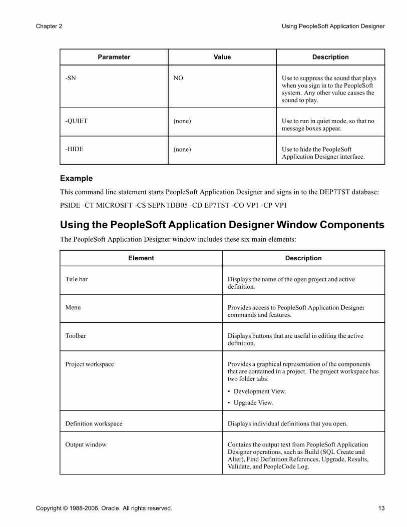
Chapter 2 Using PeopleSoft Application Designer
Parameter Value Description
-SN NO Use to suppress the sound that playswhen you sign in to the PeopleSoftsystem. Any other value causes thesound to play.
-QUIET (none) Use to run in quiet mode, so that nomessage boxes appear.
-HIDE (none) Use to hide the PeopleSoftApplication Designer interface.
ExampleThis command line statement starts PeopleSoft Application Designer and signs in to the DEP7TST database:
PSIDE -CT MICROSFT -CS SEPNTDB05 -CD EP7TST -CO VP1 -CP VP1
Using the PeopleSoft Application Designer Window ComponentsThe PeopleSoft Application Designer window includes these six main elements:
Element Description
Title bar Displays the name of the open project and activedefinition.
Menu Provides access to PeopleSoft Application Designercommands and features.
Toolbar Displays buttons that are useful in editing the activedefinition.
Project workspace Provides a graphical representation of the componentsthat are contained in a project. The project workspace hastwo folder tabs:
• Development View.
• Upgrade View.
Definition workspace Displays individual definitions that you open.
Output window Contains the output text from PeopleSoft ApplicationDesigner operations, such as Build (SQL Create andAlter), Find Definition References, Upgrade, Results,Validate, and PeopleCode Log.
Copyright © 1988-2006, Oracle. All rights reserved. 13
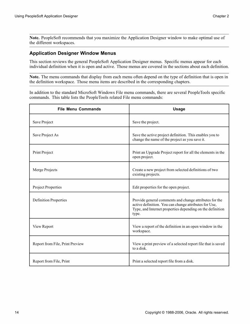
Using PeopleSoft Application Designer Chapter 2
Note. PeopleSoft recommends that you maximize the Application Designer window to make optimal use ofthe different workspaces.
Application Designer Window MenusThis section reviews the general PeopleSoft Application Designer menus. Specific menus appear for eachindividual definition when it is open and active. Those menus are covered in the sections about each definition.
Note. The menu commands that display from each menu often depend on the type of definition that is open inthe definition workspace. Those menu items are described in the corresponding chapters.
In addition to the standard MicroSoft Windows File menu commands, there are several PeopleTools specificcommands. This table lists the PeopleTools related File menu commands:
File Menu Commands Usage
Save Project Save the project.
Save Project As Save the active project definition. This enables you tochange the name of the project as you save it.
Print Project Print an Upgrade Project report for all the elements in theopen project.
Merge Projects Create a new project from selected definitions of twoexisting projects.
Project Properties Edit properties for the open project.
Definition Properties Provide general comments and change attributes for theactive definition. You can change attributes for Use,Type, and Internet properties depending on the definitiontype.
View Report View a report of the definition in an open window in theworkspace.
Report from File, Print Preview View a print preview of a selected report file that is savedto a disk.
Report from File, Print Print a selected report file from a disk.
14 Copyright © 1988-2006, Oracle. All rights reserved.
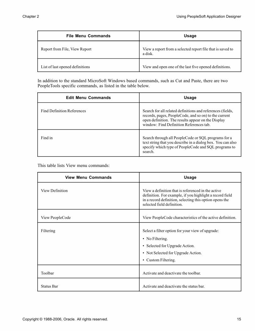
Chapter 2 Using PeopleSoft Application Designer
File Menu Commands Usage
Report from File, View Report View a report from a selected report file that is saved toa disk.
List of last opened definitions View and open one of the last five opened definitions.
In addition to the standard MicroSoft Windows based commands, such as Cut and Paste, there are twoPeopleTools specific commands, as listed in the table below.
Edit Menu Commands Usage
Find Definition References Search for all related definitions and references (fields,records, pages, PeopleCode, and so on) to the currentopen definition. The results appear on the Displaywindow: Find Definition References tab.
Find in Search through all PeopleCode or SQL programs for atext string that you describe in a dialog box. You can alsospecify which type of PeopleCode and SQL programs tosearch.
This table lists View menu commands:
View Menu Commands Usage
View Definition View a definition that is referenced in the activedefinition. For example, if you highlight a record fieldin a record definition, selecting this option opens theselected field definition.
View PeopleCode View PeopleCode characteristics of the active definition.
Filtering Select a filter option for your view of upgrade:
• No Filtering.
• Selected for Upgrade Action.
• Not Selected for Upgrade Action.
• Custom Filtering.
Toolbar Activate and deactivate the toolbar.
Status Bar Activate and deactivate the status bar.
Copyright © 1988-2006, Oracle. All rights reserved. 15

Using PeopleSoft Application Designer Chapter 2
View Menu Commands Usage
Project Workspace Activate and deactivate the project workspace display.
Output Window Activate and deactivate the output window display.
This table lists Insert menu commands:
Insert Menu Commands Usage
Current Definition into Project Insert the active definition into the project.
Definitions into Project Display a dialog box to insert definitions into the project.
Build Menu Commands Usage
Current Definition Display a dialog box to build or alter the record definitionthat is currently active in the definition workspace.
Project Display a dialog box to build (SQL Create and SQLAlter) all records in the project.
Settings Display a dialog box in which you set parameters thatapply to build operations.
This table lists the Debug menu commands:
Debug Menu Commands Usage
PeopleCode Debugger Mode Start the PeopleCode Debugger, invoking a debuggingsession and causing a full Debug menu to appear. Whenin Debugger mode, a Local Variables pop-up windowdisplays in the definition workspace.
See PeopleTools 8.4 PeopleBook: PeopleSoftPeopleCode Developer’s Guide, "Debugging YourApplication."
This table lists the Tools menu commands:
16 Copyright © 1988-2006, Oracle. All rights reserved.

Chapter 2 Using PeopleSoft Application Designer
Tools Menu Commands Usage
Validate Project Validate attributes of the active project.
Validate Database for WSRP Validates all of the appropriate definitions within adatabase for WSRP compliance.
See Enterprise PeopleTools 8.48 PeopleBook: InternetTechnology, “UsingWSRP to Consume and ProduceRemote Portlets,” ValidatingWSRP-Compliance.
Compile All PeopleCode Validate all of the PeopleCode in the current database.
Compile Project PeopleCode Validate the PeopleCode in the current project.
Diff / Merge Project PeopleCode Compare and merge two PeopleCode definitions duringan upgrade.
Diff / Merge External Text Compare and merge two versions of an external text file(such as a Data Mover script or a SQL script) during anupgrade.
Compare and Report Compares two projects and reports on the differences.
Copy Project Copy the current project to a database or a file, or export aproject from a file to your database.
Data Administration Open dialog boxes that describe space allocation in thedatabase.
Change Control Open dialog boxes to view history or set systemwidechange control options as the administrator.
Upgrade Upgrade an application project.
Translate Translate base and operator language databases.
Miscellaneous Definitions Set custom field formats, toolbars, colors, styles, accessprofiles, and file type codes.
Copyright © 1988-2006, Oracle. All rights reserved. 17
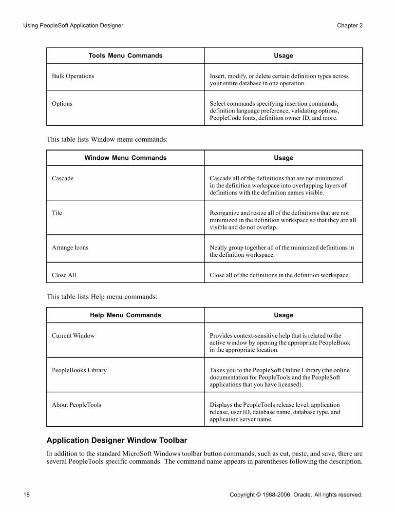
Using PeopleSoft Application Designer Chapter 2
Tools Menu Commands Usage
Bulk Operations Insert, modify, or delete certain definition types acrossyour entire database in one operation.
Options Select commands specifying insertion commands,definition language preference, validating options,PeopleCode fonts, definition owner ID, and more.
This table lists Window menu commands:
Window Menu Commands Usage
Cascade Cascade all of the definitions that are not minimizedin the definition workspace into overlapping layers ofdefinitions with the definition names visible.
Tile Reorganize and resize all of the definitions that are notminimized in the definition workspace so that they are allvisible and do not overlap.
Arrange Icons Neatly group together all of the minimized definitions inthe definition workspace.
Close All Close all of the definitions in the definition workspace.
This table lists Help menu commands:
Help Menu Commands Usage
Current Window Provides context-sensitive help that is related to theactive window by opening the appropriate PeopleBookin the appropriate location.
PeopleBooks Library Takes you to the PeopleSoft Online Library (the onlinedocumentation for PeopleTools and the PeopleSoftapplications that you have licensed).
About PeopleTools Displays the PeopleTools release level, applicationrelease, user ID, database name, database type, andapplication server name.
Application Designer Window ToolbarIn addition to the standard MicroSoft Windows toolbar button commands, such as cut, paste, and save, there areseveral PeopleTools specific commands. The command name appears in parentheses following the description.
18 Copyright © 1988-2006, Oracle. All rights reserved.

Chapter 2 Using PeopleSoft Application Designer
Open the Definition Properties dialog box (File, Definition Properties).
Open the Build dialog box (Build, Current Definition).
Toggle the display of the project workspace (View, Project Workspace).
Project WorkspaceView projects and their associated definitions in the project workspace. A project organizes a collection ofdefinitions in logical groups for easier development, adaptation, maintenance, and upgrade.
Project workspace shown with a project open
Work with a development project or an upgrade project by selecting either the Development tab or the Upgradetab at the bottom of the project workspace.
The text on the Development and Upgrade tabs might not appear if there is not enough room to displayit onscreen.
Definition WorkspaceUse the definition workspace to create and modify definitions, which can be maximized, minimized, cascaded,or tiled in the workspace.
Output WindowThe output window displays status messages of various PeopleSoft Application Designer operations. Theoutput is organized into different categories by using tabs at the bottom of the window.
Copyright © 1988-2006, Oracle. All rights reserved. 19

Using PeopleSoft Application Designer Chapter 2
The text displayed in the output window is context-sensitive, enabling you to select it to perform relatedoperations. For example, if you have a field definition open, select Edit, Find Definition References to list thedefinitions that reference the active field definition. The list appears in the output window. Then, double-clickany of the related definitions listed to open them.
The output window contains several tabs that relate to numerous functions that you can perform withPeopleSoft Application Designer:
Tab Usage
Build Create tables, indexes, and views, and alter tables.If you select the Log to Output Window option in theBuild settings, then errors, warnings, and informationalmessages appear here. You can control the level of detailthat appears.
Find Definition References View definitions that are used or referenced by otherdefinitions. Double-click a definition to open it.
Upgrade View upgrade actions that are initiated from PeopleSoftApplication Designer.
Results View messages related to project operations, like openinga project or inserting definitions into the project.
Validate Validate projects and components, and view the results.
Find in View the Find Indialog box output. Double-click adefinition to open it. The Find In search can be limited toa specific project, rather than the entire database.
PeopleCode Log View errors that you receive when you’re in the debuggerstepping through code.
Setting PeopleTools OptionsYou can set preferences for various features in the Options dialog box. Access the Options dialog box byselecting Tools, Options. Each tab controls options for different areas of PeopleSoft Application Designer.Most of these options are described in further detail in other, more relevant areas of the PeopleBooksdocumentation. The table below provides a general description of each tab and a link to further detailsabout the options:
Project Set various project options.
See Chapter 3, “Working With Projects,” Setting Project Options, page 55.
Validate Use this tab to set project validation options and to activate the spell checkfeature for PeopleSoft Application Designer.
See Chapter 3, “Working With Projects,” Validating Projects, page 56.
20 Copyright © 1988-2006, Oracle. All rights reserved.

Chapter 2 Using PeopleSoft Application Designer
See Chapter 2, “Using PeopleSoft Application Designer,” Enabling SpellCheck, page 43.
Editors Set Word Wrap options for the various editors in PeopleSoft ApplicationDesigner.
See Enterprise PeopleTools 8.48 PeopleBook: PeopleCode Developer’sGuide, “Using the PeopleCode Editor”.
See Enterprise PeopleTools 8.48 PeopleBook: PeopleCode Developer’sGuide, “Using the SQL Editor”.
General Set the Undo/Redo Buffer Depth. This option determines how many layers ofeditability you have in the PeopleSoft Application Designer. The default valueis 10. This means that you can “undo” up to 10 immediately previous actionstaken, such as adding or deleting page fields from a page.Set the Maximum Most Recently Used Definition. The most recently useddefinitions appear at the bottom of the File menu. The default value is 5.Choose the destination you would like for your report output in the ReportOutput Directory field.
Owner Id Set the default owner Id for new definitions you create. Alternatively,leave the option blank, the default, to allow users to select the owner Idthey wish. The Owner Id helps identify which applications team last madea change to a definition.
Image Set the preferred storage format for newly created image definitions.
See Chapter 15, “Creating Image Definitions,” Specifying the Image StorageFormat, page 375.
Browser Enter here the base URI to be used by the browser to locate the applicationand the node name.
See Chapter 2, “Using PeopleSoft Application Designer,” ConfiguringBrowser Options, page 44.
Working with PeopleCodeThis section provides a brief explanation of working with PeopleCode and discusses the main developmenteditors.
PeopleCode is the structured programming language built into PeopleTools that extends the functionality ofthe PeopleTools environment. All PeopleCode programs are associated with a parent definition. ThesePeopleCode programs are considered part of the definitions of their parent components and you edit them aspart of the definitions.
PeopleCode programs can be associated with many items, such as record fields, pages, components, andapplication messages. You can access any PeopleCode program from its related definition. As an example, oneof the ways to access PeopleCode from one of the many places that PeopleCode is stored is to access RecordField PeopleCode from an open record definition.
Copyright © 1988-2006, Oracle. All rights reserved. 21

Using PeopleSoft Application Designer Chapter 2
Accessing FieldChange PeopleCode from the BEGIN_DT field
To view Record Field PeopleCode from PeopleSoft Application Designer:
1. Open a record definition in PeopleSoft Application Designer.2. Click the View PeopleCode toolbar button to view the PeopleCode display for the record.3. Select a field containing PeopleCode in the record definition.4. Double-click the cell under the column heading for the type of PeopleCode that you want to view.You can also right-click on a definition and use the pop-up menu to access or view the PeopleCode.
See AlsoEnterprise PeopleTools 8.48 PeopleBook: PeopleCode Developer’s Guide, “Accessing PeopleCode andEvents”
Using the Development EditorsThis section describes the three main development editors:
• SQL editor• PeopleCode editor• Application Packages editor
SQL EditorThe SQL Editor is a tool that enables you to construct SQL definitions. SQL Editor has a similar look and feelto the PeopleCode editor. You can access SQL Editor from these definitions:
22 Copyright © 1988-2006, Oracle. All rights reserved.

Chapter 2 Using PeopleSoft Application Designer
• Records that are based on SQL and dynamic view.• PeopleSoft Application Engine actions.• PeopleCode editor.
PeopleCode EditorAny method of accessing PeopleCode programs displays a window where PeopleCode programs can be inputor modified. This window is the PeopleCode editor. The PeopleCode editor enables you to edit and navigateall PeopleCode programs that belong to the same parent definition.
On the left side of the window is a drop-down list box showing the current field and other available fields,records, and components. Any field with PeopleCode attached is listed in bold. The right side of the windowhas a drop-down list box listing the current PeopleCode event and other acceptable events for that definition.Events already containing PeopleCode for that definition are listed in bold.
Working in the PeopleCode editor
Application Packages EditorFrom an Application Package you can access the PeopleCode programs that are associated with the classesof the package. The Application Packages editor and the PeopleCode editor interfaces are similar. You canadd, delete, and change text: you can use the find and replace function; you can validate the syntax. Whenyou save your application package, the code is automatically formatted (indented and so on), just as it is inthe PeopleCode editor.
See AlsoEnterprise PeopleTools 8.48 PeopleBook: PeopleCode Developer’s Guide, “Using the SQL Editor”
Enterprise PeopleTools 8.48 PeopleBook: PeopleCode Developer’s Guide, “Using the PeopleCode Editor”
Enterprise PeopleTools 8.48 PeopleBook: PeopleCode Developer’s Guide, “Creating Application Packagesand Classes”
Copyright © 1988-2006, Oracle. All rights reserved. 23

Using PeopleSoft Application Designer Chapter 2
Working with DefinitionsThis section provides as overview of definitions and discusses how to:
• Open definitions.
• View definitions.
• View and edit definition properties.
• Create definitions.
• Save definitions.
• Close definitions.
• Rename definitions.
• Delete definitions.
• Find definitions.
Understanding DefinitionsYou can create or modify many types of definitions in PeopleSoft Application Designer. This table listsdevelopment definitions:
Definition Description
Activity Workflow map showing the individual steps, events, androutings that comprise a complete activity in a businessprocess.
Analytic Model Analytic models are used exclusively with the PeopleSoftAnalytic Calculation Engine.
See Enterprise PeopleTools 8.48 PeopleBook:PeopleSoft Analytic Calculation Engine, “Designing andEditing Analytic Models”.
Application Engine Program comprising SQL statements and PeopleCodeprograms to run in batch mode as an alternative to usingCOBOL or SQR programs.
Application Package Used to create Application Classes, which could be usedto either extend the functionality of existing PeopleToolsclasses (Rowset, Array, and so on) or to create your ownclasses.
Approval Rule Set Workflow maps that provide a visual representation ofapproval rules. Virtual Approver reads approval rule setsto determine who must approve transactions.
24 Copyright © 1988-2006, Oracle. All rights reserved.

Chapter 2 Using PeopleSoft Application Designer
Definition Description
Business Interlink Provides a gateway between PeopleSoft applications andthe services of an external system.
Business Process Workflow maps that provide a visual overview of theactivities involved in a procedure.
Component Represents a logical business transaction or a set oflogically related pages that are processed together.
Component Interface Externalizes access to a component so that it can be usedby a third party or an application message.
Field Individual pieces of data—such as an employee ID—thatcan be entered by the user and stored in the database, in acolumn on a table, or in a view.
File Layout Definition (or mapping) of a file to be processed. Itidentifies where data fields are located in a file.
HTML Definition that represents static HTML that can beinlcuded on a page definition.
Image Stores and displays images, such as employee photos,product pictures, and so on.
Menu Enables access to the components that you build and thepages contained in the components.
Message Based on a multilevel structure, similar to components,that defines the data to insert into the application messageat runtime.
Message Channel These correspond to groups of message definitions andhelp order messages properly, enhance scalability, andprovide a simple way to define processing characteristicsof many similar messages as a single group.
Mobile Page A PeopleSoft Pure Internet Architecture page based ona synchronizable component interface for display ondisconnected mobile devices, such as laptops or PDAs.
Page Pages provide a way to enter, view, and edit data online.The system validates user input, writes it to the database,and retrieves and displays it upon request.
Copyright © 1988-2006, Oracle. All rights reserved. 25

Using PeopleSoft Application Designer Chapter 2
Definition Description
Project User-defined collection of related definitions createdfor developing, adapting, or upgrading a PeopleSoftapplication.
Problem Type Used in optimization to tie the optimization applicationrecords, the optimization transactions, and theoptimization plug-in together as one entity.
Record All of the data that resides in PeopleSoft applications isstored in tables, or records, as part of a relational databasesystem. Each record definition describes the propertiesof an underlying SQL table.
SQL Can be entire SQL programs or fragments of SQLstatements that you want to reuse.
Style Sheet Collection of styles that can be used by PeopleSoft PureInternet Architecture application pages.
Opening DefinitionsUse the definition workspace when accessing or creating definitions.
To open a definition:
1. Select File, Open or click the corresponding toolbar button.The Open Definition dialog box appears.
2. Select the type of definition that you want to open from the Definition drop-down list box.
3. Provide selection criteria.
Enter a definition name or description (or the beginning characters of either). Other selection criteriaoptions might be available, depending on the definition type.
4. Click Open, or press ENTER, to display definitions matching the selection criteria that you entered.
To clear the current selection criteria and start over, click New Search. To change how the search list isdisplayed, perform one of these actions:
• Click the List button to see only the names of the definitions.
• Click the Details button to see the names and descriptions, which is the default.
5. Select the definition to open.
6. Double-click the definition that you want to open in the definition workspace, or highlight the definitionand click Open.
You can also use the shift-click selection technique to select more than one definition to open in a singleaction, or right-click to view a pop-up menu, where you can open, print, rename, or delete the selecteddefinition.
26 Copyright © 1988-2006, Oracle. All rights reserved.
Chapter 2 Using PeopleSoft Application Designer
Note. When the definition is open and able to be modified, "Ready" appears in the lower left-handcorner of the workspace.
Viewing DefinitionsIn the project workspace, you can view a definition that is referenced by the active definition.
To view a definition, select View, View Definition. You can also right-click the definition to be referencedand select View Definition from the pop-up menu.
Viewing and Editing Definition PropertiesEach definition type has properties that are associated with it. To view or edit definition properties, selectFile, Definition Properties. You can also click the toolbar button or press ALT+ENTER.or right-click on thedefinition and select Properties from the pop-up menu.
The Definition Properties dialog box almost always includes a General tab that provides a place to displayand enter descriptions and comments regarding the definition. An optional Owner ID drop-down list box isprovided to designate the owner of an individual definition. This helps identify which application teamlast made a change to a definition. Set the default owner ID for new definitions in the Options dialog box,Owner Id tab.
Copyright © 1988-2006, Oracle. All rights reserved. 27

Using PeopleSoft Application Designer Chapter 2
Property sheet example
With PeopleSoft Application Designer, every definition that you can open (menus, pages, components, records,fields, and so on) has an associated property sheet. Definition properties that are specific to the definition typeare grouped together in these definition property sheets. For example:
• Record Type and Record Use properties are both found in the Definition Properties sheet for records.
• Translates are found in the Definition Properties sheet for fields.
• Menu groups and menu labels are found in the Definition Properties sheet for menus.
• Search record, actions, and internet settings are found in the Definition Properties sheet for components.
Creating DefinitionsWhen building or adapting an application, try to use existing definitions as much as possible; when that’s notpossible, create new definitions.
To create a new definition:
1. Select File, New or click the corresponding toolbar button.2. Select the definition type.
28 Copyright © 1988-2006, Oracle. All rights reserved.
Chapter 2 Using PeopleSoft Application Designer
The new definition appears in the definition workspace.
Saving DefinitionsTo retain the changes that you make, you must save the definition. However, you must name new definitionsbefore you can save them.
To save a definition:
1. Click the Save button on the toolbar, or select either File, Save or File, Save As to save a definition.The Save and Save As commands save a single definition. Use the File, Save All command or the Save Alltoolbar button to save all open definitions at once.
2. If you’re saving a page or component, specify the language or market.For a page definition, the Language drop-down list box appears; for a component, the Market drop-downlist box appears.
Definition Naming ConventionsWhen naming definitions, use the following guidelines:
• Use only uppercase alphabetic characters (A–Z), numeric characters (0–9), or underscore (_). Other specialcharacters, such as the dash (—), dollar sign, number sign, question mark, and so on, are not permitted.
• Names must begin with an alphabetic character.• Embedded spaces are not permitted.Instead, use an underscore.
• Avoid using accented characters.Names containing these characters may not sort consistently, depending on workstation or locale settings,which results in problems during an upgrade.
• System definitions such as records, fields, styles, and so on, generally have a name and a label or description.Generally, it is recommended to use US-ASCII characters only for the definition name. Labels ordescriptions, which are used for the display to the user, can contain non-ASCII characters.
Note. Existing Business Process and Business Process Map definitions may already contain mixed casecharacters. Nonetheless, newly created definition names must be all uppercase.
Closing DefinitionsTo close a definition, either select File, Close or click the Close Window icon on the title bar of the activedefinition’s window. You can also select Window, Close All to close all open definitions.
Renaming DefinitionsYou can rename existing definitions in a database at any time.
Copyright © 1988-2006, Oracle. All rights reserved. 29

Using PeopleSoft Application Designer Chapter 2
Rename Definition dialog box
To rename a definition in the database:
1. Select File, Rename.The Rename Definition dialog box looks like the Open Definition dialog box, and you select definitionsin the same way.
2. Specify the definition type and any selection criteria that are useful in locating the definition that youwant to rename.The Rename Definition dialog box does not have a Select button. So, after entering either a partial name ordescription of the definition, press ENTER to retrieve a list of definitions matching your selection criteria.
3. Select the definition that you want to rename.4. Click the Rename button in the dialog box and double-click the selected definition, or right -click toselect Rename from the pop-up menu.The selected definition name in the Rename Definition dialog box is in edit mode.
5. Change the selected definition name and press ENTER.You are prompted to close any open definitions, if any are open, before you can save the new name. Youare also prompted with a Confirm Rename dialog box before you can save the change.
6. Click OK to complete the renaming of the selected definition.
30 Copyright © 1988-2006, Oracle. All rights reserved.

Chapter 2 Using PeopleSoft Application Designer
Deleting DefinitionsDeleting a definition is different from removing a definition from a project. When you remove a definitionfrom a project, the reference to the definition is removed from the project, but the definition still exists in thedatabase and thus may be a part of any other project. Deleting a definition, however, permanently removes thedefinition from the database. Any projects or other definitions that contains the deleted definition are affected.
Before deleting a definition you should find all references to that definition by running the Find DefinitionReferences process. For example, a field definition that you want to delete may be referenced by bothrecord and page definitions.
Note. If you delete a component definition, you must delete all component interfaces that are based on thatdefinition.
Note. A component definition must contain at least one page. If you attempt to delete a page definition that isthe only page definition within a component, the system does not allow the delete to occur and displays anerror message. If the page definition is the only page within a component, the error message appears during aFile, Delete or during an upgrade copy to database (with a Delete action).
Delete Definition dialog box
To delete a definition from the database:
1. Select File, Delete.The Delete Definition dialog box looks like the Open Definition dialog box, and you select definitions inexactly the same way.
Copyright © 1988-2006, Oracle. All rights reserved. 31
Using PeopleSoft Application Designer Chapter 2
2. Specify the definition type and any selection criteria that are useful in locating the definition that youwant to delete.After entering either a partial name or description of the definition, press ENTER to retrieve a list ofdefinitions matching your selection criteria.
3. Select the definition that you want to delete.To select multiple definitions, hold down either SHIFT or CTRL while clicking the appropriate definitions.
4. Click the Delete button and confirm that you want to delete the selected definition.
Finding DefinitionsBefore making significant changes, such as deleting a definition, it is critical to see what other parts of theapplication may be impacted by this change. The Find Definition References feature performs a comprehensivesearch of the database pinpointing all definitions in which the changed definition is located.
Although a project keeps track of your definitions, the definitions are not actually embedded in the project.
Note. There is a distinction between related definitions and referenced definitions. A related definition isone that is used by the current definition. A definition reference is one that uses the current definition. Forexample, in the case of a component, pages in the component are related definitions. The menus that use thecomponent are its definition references.
32 Copyright © 1988-2006, Oracle. All rights reserved.

Chapter 2 Using PeopleSoft Application Designer
Finding definition references
To find definition references:
1. Open the definition in the definition workspace.2. Select Edit, Find Definition References, or right-click the definition and select Find Definition Referencesfrom the pop-up menu.After you select this item, a search of the database takes place, and the results appear on the Find DefinitionReferences tab of the output window.
3. Select any definition that is displayed in the output window by double-clicking it.The selected definition opens in the definition workspace.
4. After you find a definition, select the definition reference and right-click to view the pop-up menu.
Note. Double-clicking any entry in the Find Definition References output window opens the appropriatemode of PeopleSoft Application Designer. If you double-click a related record that was found, the recordopens, and the field for which you were looking is highlighted.
Copyright © 1988-2006, Oracle. All rights reserved. 33

Using PeopleSoft Application Designer Chapter 2
Using the Multiple Document InterfacePeopleSoft Application Designer makes use of an MDI. This means that each window in the definitionworkspace of PeopleSoft Application Designer represents a view of a definition, and you can have multiplewindows open at the same time. These definition windows must stay inside the borders of the definitionworkspace, but they can be maximized, minimized, cascaded, or tiled in that space.
You can have different types of definition windows open at the same time, such as menu, field, record, andpage windows. This enables you to work with different definitions simultaneously, simplifying the process ofdesigning a group of related definitions.
Active WindowsAlthough you can have multiple windows open at the same time, only one window can be active at anymoment. Make a window active by selecting it in the definition workspace. The active window always appearson top with the title bar in active window title color.
In addition to clicking on a window to make it active, you can also use the Window menu. This menu displaysthe windows that are currently open with a check mark next to the active one. Change the window thatis currently active by selecting it from the menu.
Window menu
Other commands from the Window menu include Cascade, Tile, Arrange Icons, or Close All windows.
Using Drag-and-DropPeopleSoft Application Designer makes ample use of drag-and-drop mouse techniques. For example, you candrag a field from a record definition and drop it onto a page definition. You can then drag the page onto acomponent and drag the component onto a menu. Using the drag-and-drop technique is faster and simpler thanusing menu commands to manipulate definitions.
To drag and drop a definition:
1. Open the definition in either the project workspace or the definition workspace from which you want todrag.
34 Copyright © 1988-2006, Oracle. All rights reserved.

Chapter 2 Using PeopleSoft Application Designer
For example, to drag a field from an existing record definition to a new page definition, first open therecord containing the field. You can open it in the definition workspace or expand the record in theproject workspace so that the fields are displayed. With the appropriate field displayed, you can drag anddrop it into another definition.
2. Open the definition to which you want to drag.3. Drag the definition from one definition to the other.
Using Dynamic Toolbars and MenusThe PeopleSoft Application Designer toolbar and menu changes based on the type of definition that is active.For example, when a page definition is active, the toolbar displays buttons that represent the definitions thatyou can add to a page. This technique is also known as morphing.
The change is so subtle that it can be missed easily. This is because the menu bar names are consistent betweendefinition types. However, if you look at the menu items and toolbars closely, you see a distinct difference. Forexample, if a page window is active, the menus and toolbars change to include actions and options applicableto a page definition—as in the Show Grid option on the View menu and the introduction of the Layout menu.In addition, page-specific toolbars are also displayed.
In the same respect, if a record window is active, the menus and toolbars morph to include actions and optionsapplicable to a record definition. For example, different options are available on the View menu (such as View,Field Display, and so on). Different toolbar buttons for record definition actions also appear.
Using Pop-up MenusPop-up menus are context-sensitive menus that appear at the current location of the mouse pointer wheneveryou click the alternate mouse button (typically, the right mouse button). They provide efficient access tonumerous PeopleSoft Application Designer commands. Because pop-up menus appear at the current locationof the pointer, they eliminate the need to move the pointer up to the menu bar or to a toolbar. A pop-up menucontains only the commands that apply to the selected definition or the current context.
Copyright © 1988-2006, Oracle. All rights reserved. 35

Using PeopleSoft Application Designer Chapter 2
Component definition pop-up menu
Configuring the EnvironmentPeopleSoft Application Designer is highly configurable, enabling you to tailor the tool to your needs orpreferences.
Splitter BarsA splitter bar is a thin vertical or horizontal bar that separates windows inside a parent window. Using thesplitter bar enables you to resize two windows at the same time. Splitter bars are used between the projectworkspace, definition workspace, and output window.
36 Copyright © 1988-2006, Oracle. All rights reserved.

Chapter 2 Using PeopleSoft Application Designer
Splitter bars used to resize workspace easily
Drag the splitter bar to change the size of the project workspace, definition workspace, or output window.
Dockable Windows and ToolbarsYou can freely move PeopleSoft Application Designer windows and toolbars to either anchor (or dock) to partsof the main application window, or to make them float freely anywhere that you want them to appear. Whenyou dock a toolbar or window, you anchor it to the top, sides, or bottom of the main window.
To move or dock a PeopleSoft Application Designer window or toolbar, drag the window title bar or theappropriate toolbar to a new location. If you move the window or toolbar near the top, bottom, or sides of themain window, the window or toolbar snaps into place, meaning that it is docked. However, if you press andhold CTRL and then drag the window or toolbar, you can prevent it from automatically docking when it isnear the edge of the window.
Note. Use caution when running the PeopleCode Debugger with undocked windows.
View MenuThe View menu enables you to display or hide different PeopleSoft Application Designer components (such asthe project workspace, output window, and toolbar).
Copyright © 1988-2006, Oracle. All rights reserved. 37

Using PeopleSoft Application Designer Chapter 2
Working with Generated FilesWhen working with PeopleSoft Application Designer, you often generate scripts, logs, reports, and so on.When specifying the full path for a file reference in PeopleSoft Application Designer, there is a 100-character(Unicode) limit. This limit applies to all file references, which include build scripts, build logs, comparereports, and so on. For example, a reference to a build log, such as c:\temp\...\psbuild.log, can’t exceed 100characters.
Using Miscellaneous DefinitionsThere are several definition types that are different from the standard definitions described above. Thesedefinitions control your work environment or have an impact on the other definitions you create. Thesemiscellaneous definitions are found under the Tools menu and include:
• Field Formats.• System Colors.• Styles.• Access Profiles.• File Type Codes.
Field FormatsPeopleTools has formatting provisions at both the field and page levels. The field format specifications affectinternal values that are stored in the database, and the page formats affect the visual presentation of values.There are several formatting options for U.S. Social Security Numbers, Canadian Social Insurance Numbers,postal codes, telephone numbers, and various currencies, dates, and times.
Custom field formats extend these formatting provisions to support the same types of data in other countries.They also support other types of formatted information, such as bank codes, credit card numbers, partnumbers, or serial numbers.
Custom field formats enable you to create your own format definitions using format notation and apply them tofields. These formats are organized into format families, which can include one or more unique formats.
See Chapter 4, “Creating Field Definitions,” Changing Format Families, page 79.
System ColorsYou can establish definitions for colors you use in your applications. You define colors by associating a colorname either with an existing color in the PeopleSoft Internet Architecture or with a custom color that youdefine. Since taste in color is subjective, PeopleTools allows individual operators to customize their colorsettings. Users can use the default color definitions you establish in PeopleSoft Application Designer, or theycan override them with their own color definitions.
38 Copyright © 1988-2006, Oracle. All rights reserved.

Chapter 2 Using PeopleSoft Application Designer
Setting system default colors
To modify the default system colors:
1. Select Tools, Miscellaneous Definitions, System Colors.2. Select the Color Name you want to modify.3. To change the color, click the Choose Color button.4. Choose from the available colors or click Define Custom Colors to create your own color.5. Click OK.The new color displays in the Sample area of the Set System Default Colors dialog box.
To create a new system color:
1. Type a new name in the Color Name field and click the New button.2. Select the Use Custom Color radio button to select a custom color.3. Click the Choose Color button.4. Choose from the available colors or click the Define Custom Colors button.5. Click OK in both dialog boxes to accept the new color.
Styles and Style InheritanceYou can create and save your own styles in PeopleSoft Application Designer. A style is a set of font andcolor attributes that can be associated with pages, field labels, field data, and so on. PeopleSoft ApplicationDesigner comes with a standard set of attributes called the System Default Style, which applies to all pages,field labels, and field data that have not been assigned a specific style. You can define as many customsets of attributes as you need.
Copyright © 1988-2006, Oracle. All rights reserved. 39

Using PeopleSoft Application Designer Chapter 2
A powerful feature of styles is inheritance. It’s easier to understand style inheritance if you think of yoursystem as a hierarchy composed of pages that are, in turn, composed of fields. You can apply styles at eachlevel of the hierarchy—sytem-wide, at the page level, or at the indivdual field level. The way style inheritanceworks is that style attributes that are not specified at the field level are inherited from the page level. If a styleis not specified at the page level, the System Default Style is inherited.
The advantage of style inheritance is that it simplifies font and color changes. For example, if you want tochange the font of all your pages from “MS Sans Serif” 8 point, bold to “Times New Roman” 9 point, italic,you only need change the System Default Style for all pages and fields that inherit the System Default Style tobe updated.
To edit the System Default Style:
1. Select Tools, Miscellaneous Objects, Styles.2. Select System Default Style in the Edit Styles dialog box.3. Click the Edit button.4. Make the desired style changes and click OK.
Access ProfilesAccess profiles are the security profiles users use to connect to the PeopleSoft database. Detailed informationabout access profiles is discussed in the Security Administration PeopleBook.
See Enterprise PeopleTools 8.48 PeopleBook: Security Administration, “Administering User Profiles,”Setting Up Access Profiles.
File Type CodesYou may need to set up file type codes when creating change projects. You create change projects to work withPeopleSoft Application Designer’s Change Packager tool to package system customizations in preparationfor an upgrade. The file type code stores generic information that is applicable to a group of files within thesame target directory.
See Enterprise PeopleTools 8.48 PeopleBook: PeopleSoft Software Updates, “Using Change Packages”.
Using Spell CheckThis section provides an overview of the spell check feature in PeopleSoft Application Designer and discusseshow to:
• Enable spell check.
• Configure browser options.
• Run spell check on a project.
Understanding Spell CheckThe PeopleSoft Application Designer spell check feature checks the spelling for user-facing labels and text inprojects and legacy data. Use this feature prior to building your application. Spell check verifies spelling onthese items:
• Message Catalog entries.
40 Copyright © 1988-2006, Oracle. All rights reserved.
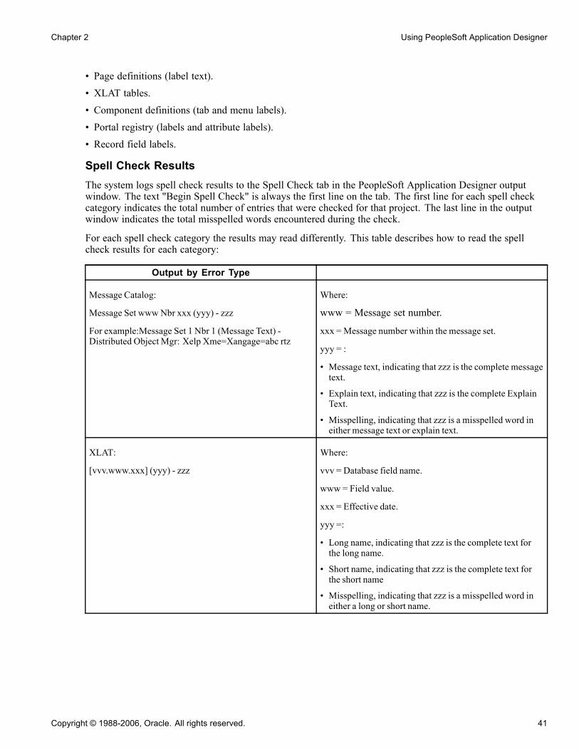
Chapter 2 Using PeopleSoft Application Designer
• Page definitions (label text).• XLAT tables.• Component definitions (tab and menu labels).• Portal registry (labels and attribute labels).• Record field labels.
Spell Check ResultsThe system logs spell check results to the Spell Check tab in the PeopleSoft Application Designer outputwindow. The text "Begin Spell Check" is always the first line on the tab. The first line for each spell checkcategory indicates the total number of entries that were checked for that project. The last line in the outputwindow indicates the total misspelled words encountered during the check.
For each spell check category the results may read differently. This table describes how to read the spellcheck results for each category:
Output by Error Type
Message Catalog:
Message Set www Nbr xxx (yyy) - zzz
For example:Message Set 1 Nbr 1 (Message Text) -Distributed Object Mgr: Xelp Xme=Xangage=abc rtz
Where:
www = Message set number.
xxx =Message number within the message set.
yyy = :
• Message text, indicating that zzz is the complete messagetext.
• Explain text, indicating that zzz is the complete ExplainText.
• Misspelling, indicating that zzz is a misspelled word ineither message text or explain text.
XLAT:
[vvv.www.xxx] (yyy) - zzz
Where:
vvv = Database field name.
www = Field value.
xxx = Effective date.
yyy =:
• Long name, indicating that zzz is the complete text forthe long name.
• Short name, indicating that zzz is the complete text forthe short name
• Misspelling, indicating that zzz is a misspelled word ineither a long or short name.
Copyright © 1988-2006, Oracle. All rights reserved. 41

Using PeopleSoft Application Designer Chapter 2
Output by Error Type
Component:
[vvv.www] Item Name xxx (yyy) - zzz
Where:
vvv = Component name.
www =Market code.
xxx = Item name for the component.
yyy =:
• Item label, indicating that zzz is the complete text for thecomponent’s item label.
• Folder tab label, indicating that zzz is the complete textfor the component’s folder tab label.
• Misspelling, indicating that zzz is a misspelled word ineither item label or folder tab label.
Portal Registry:
[ttt.uuu.vvv] www xxx (yyy) - zzz
Where:
ttt = Portal name.
uuu = C for content reference, F for folder.
vvv = Portal object name.
www =:
• Empty.
• Attribute.
• System attribute.
xxx =:
• Empty if www is empty.
• Attribute name if www is attribute.
• System attribute name if www is system attribute.
yyy =:
• Label name, indicating that zzz is the complete text forthe Label Name.
• Display name, indicating that zzz is the complete text forthe display name of an attribute.
• Misspelling, indicating that zzz is a misspelled word ineither label name or display name.
42 Copyright © 1988-2006, Oracle. All rights reserved.

Chapter 2 Using PeopleSoft Application Designer
Output by Error Type
Field Label:
[www.xxx] (yyy) - zzz
Where:
www = Field name.
xxx = Field label name.
yyy =
• Long name, indicating that zzz is the complete text forthe long name.
• Short name, indicating that zzz is the complete text forthe short name
• Misspelling, indicating that zzz is a misspelled word ineither a long or short name.
Page:
[www] Field ID xxx (yyy) - zzz
Where:
www = Page name.
xxx = Field ID within the page.
yyy =
• Label text, indicating that zzz is the complete text for thefield’s label text.
• Scroll area, indicating that zzz is the complete text forlabel text within a scroll area.
• Misspelling, indicating that zzz is a misspelled word inthe label text.
You can launch an identified definition from the output window directly by double clicking the error line.PeopleSoft Application Designer launches the appropriate content to correct the misspelling:
Error Type Launches
Message Catalog n/a
XLAT Field definition.
Component Component definition.
Portal registry Browser to display the Content or Folder Administration page.
Field label Field definition.
Page Page definition.
Enabling Spell CheckThe spell check feature is turned off by default. You enable spell check in the Options dialog box, Validatetab. Enabling the spell check option ensures that spell check is run on the designated project when youvalidate a project.
Copyright © 1988-2006, Oracle. All rights reserved. 43
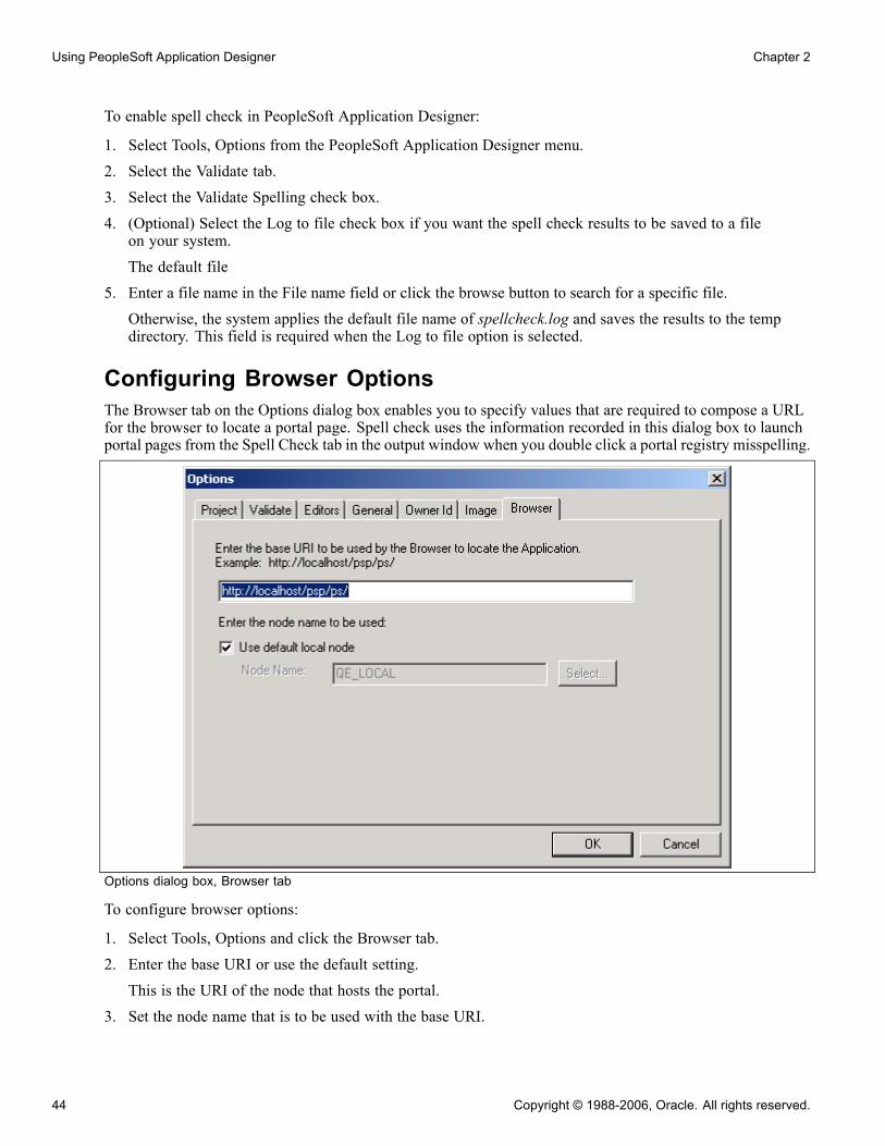
Using PeopleSoft Application Designer Chapter 2
To enable spell check in PeopleSoft Application Designer:
1. Select Tools, Options from the PeopleSoft Application Designer menu.
2. Select the Validate tab.
3. Select the Validate Spelling check box.
4. (Optional) Select the Log to file check box if you want the spell check results to be saved to a fileon your system.
The default file
5. Enter a file name in the File name field or click the browse button to search for a specific file.
Otherwise, the system applies the default file name of spellcheck.log and saves the results to the tempdirectory. This field is required when the Log to file option is selected.
Configuring Browser OptionsThe Browser tab on the Options dialog box enables you to specify values that are required to compose a URLfor the browser to locate a portal page. Spell check uses the information recorded in this dialog box to launchportal pages from the Spell Check tab in the output window when you double click a portal registry misspelling.
Options dialog box, Browser tab
To configure browser options:
1. Select Tools, Options and click the Browser tab.2. Enter the base URI or use the default setting.This is the URI of the node that hosts the portal.
3. Set the node name that is to be used with the base URI.
44 Copyright © 1988-2006, Oracle. All rights reserved.

Chapter 2 Using PeopleSoft Application Designer
The Use default local node check box is selected by default. Clearing this check box enables the Selectbutton, which allows you to set the node name in the Select Node dialog box.The Select Node dialog box displays the list of available nodes by project. You can perform a search forthe appropriate node by clicking the Select button.
Building and Maintaining DataThis section discusses:
• Data building and maintenance.
• Creating SQL tables.
Data Building and MaintenanceThe underlying database definitions must be kept in sync with PeopleSoft definitions. Therefore, fromPeopleSoft Application Designer, you must:
• Submit SQL Alter and Create commands for all types of database definitions.• Manage the database index.• Manage the table space.• Manage the DDL model for tables, indexes, and table spaces.
Creating SQL TablesTo access data, you must create a SQL table and then store data in the fields and records. The process ofrunning the SQL necessary to synchronize the database with records, indexes, and DDL is called Build.
The Build feature processes definitions at these three levels:
• Current record.
• Selected records in the project workspace.
• All records in the project.
See AlsoChapter 7, “Administering Data,” page 137
Copyright © 1988-2006, Oracle. All rights reserved. 45

Using PeopleSoft Application Designer Chapter 2
46 Copyright © 1988-2006, Oracle. All rights reserved.

CHAPTER 3
Working With Projects
This chapter provides an overview of projects and discusses how to:
• View projects.
• Create and save projects.
• Set project properties.
• Insert definitions into a project.
• Remove definitions from a project.
• Merge projects.
• Use change projects.
• Set project options.
• Validate projects.
• Set system IDs.
Understanding ProjectsWhile not one of the eight steps of application development, using projects is an efficient way to organize yourdefinitions as you develop and configure your application. A project simply keeps track of all definition typesas a simple list of definition names; it is not where the definitions are stored. Development definitions existoutside of the project in your PeopleSoft database.
You are not required to use projects in PeopleSoft Application Designer; you can create and edit individualdefinitions without associating them with a project. However, using projects can help you:
• Organize related definitions.• Understand relationships among definitions.• Coordinate the work of several developers.• Streamline upgrade tasks.• Search for fields or records.• Access related definitions easily.
Copyright © 1988-2006, Oracle. All rights reserved. 47

Working With Projects Chapter 3
Viewing ProjectsOn the left-hand side of your screen, the project workspace displays one project at a time and all of itsdefinitions, making them easily accessible for opening and editing. It includes two views representing thecollection of definitions in the project: Development and Upgrade. Switch between the views by selecting thefolder tabs at the bottom of the project workspace.
This section discusses how to:
• Access definitions for a project.• Using the upgrade view.
Accessing Definitions for a ProjectIn the Development view, the project folder contains a folder for each definition type included in the project.To open folders and view related definitions, click the expand (+) button. Access the definitions for a projectby double-clicking the definition.
Development view in the project workspace
The definitions appear in a project tree, organized by definition type. The project tree enables you to see alldefinitions associated with the project and their connection, by showing the definitions in an hierarchicalformat. By expanding definitions that have nested levels, such as records, you’ll see the field definitionsincluded in that record.
48 Copyright © 1988-2006, Oracle. All rights reserved.

Chapter 3 Working With Projects
Using the Upgrade ViewThe Upgrade view helps to streamline the migration of definitions—such as records, pages, orPeopleCode—from one PeopleSoft database to another. It displays all of the definitions available for upgradeand attributes related to the upgrade process. When you double-click a definition type in the Upgrade view, anupgrade definition window appears in the definition workspace, displaying the definitions of that type that areavailable for upgrade and the associated upgrade options.
Upgrade view in the project workspace
This view is important when moving changes into production and when upgrading to new PeopleSoft releases.Definitions in development projects and upgrade projects are interchangeable, meaning that components thatwere developed in PeopleSoft Application Designer can be copied or compared using the Upgrade view.
See AlsoChapter 20, “Upgrading with PeopleSoft Application Designer,” page 451
Creating and Saving ProjectsThis section discusses how to:
• Create a new project.• Save a project.
Note. Changes that you make to a definition in a project are also reflected outside the project. Before youchange a definition in a project, be aware of how it might affect other definitions outside the project. Forexample, when you rename or delete a field, you do so globally. Although you can enter a project name asselection criteria in certain PeopleSoft Application Designer dialog boxes (such as Open, Rename, and Delete),this is just to narrow the list of definitions returned in the selection list.
Copyright © 1988-2006, Oracle. All rights reserved. 49

Working With Projects Chapter 3
Creating a New ProjectWhen you start PeopleSoft Application Designer, an empty project titled "Untitled" always appears, whetheryou use the project or not. Unlike other definitions, only one project can be open at a time. AlthoughPeopleSoft encourages you to develop in projects, you can hide the project workspace window and ignore theproject entirely.
To create a new project:
1. Select File, New.2. Highlight Project as the new definition type to create, and click OK.
Note. Another way to create a new project is to open an existing project. Then, select File, Save Project As,and enter a new name for the project. All of the existing definitions in the project are also copied.
See Chapter 2, “Using PeopleSoft Application Designer,” Saving Definitions, page 29.
To open an existing project, follow the same procedure as you would for any other definition type.
See Chapter 2, “Using PeopleSoft Application Designer,” Opening Definitions, page 26.
Saving a ProjectUse a different command when saving an entire project than when saving other types of definitions.
To save a project, select File, Save Project. You can also select File, Save Project As to save the projectwith a new name. This is a good way to make a copy of a project, because the original project still existsunder the original name.
The save toolbar button saves whichever definition is active in the definition workspace, but it cannot beused to save an entire project.
Setting Project PropertiesUse the Project Properties dialog box to enter information about the project. Access Project Properties fromthe File menu.
50 Copyright © 1988-2006, Oracle. All rights reserved.

Chapter 3 Working With Projects
Project Properties dialog box
In the General tab, enter a description of the project and any additional comments you might want others to beaware of when using the project. Select the Change Project check box only if you are creating a change projectto be used with the Change Packager. Selecting this option enables the Update IDs and the Pre-Requisites tabs,also used only with the Change Packager.
See Enterprise PeopleTools 8.48 PeopleBook: PeopleSoft Software Updates, “Using Change Packages”.
Select the appropriate Owner ID for the project. The Owner ID allows for a way to identify which definitionsare owned by which PeopleSoft applications, such as PeopleSoft General Ledger, Accounts Receivables, andso on. The values in the drop-down list box are translate table values associated with the OBJECTOWNERIDfield.
Inserting Definitions Into a ProjectYou can add definitions to a project by selecting Definitions into Project from the Insert menu.
To insert a definition into a project:
You can:
• Insert definitions individually.• Select a number of definitions to insert as a group.
Copyright © 1988-2006, Oracle. All rights reserved. 51
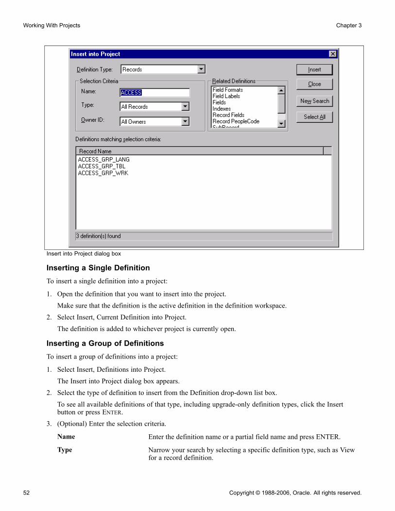
Working With Projects Chapter 3
Insert into Project dialog box
Inserting a Single DefinitionTo insert a single definition into a project:
1. Open the definition that you want to insert into the project.Make sure that the definition is the active definition in the definition workspace.
2. Select Insert, Current Definition into Project.The definition is added to whichever project is currently open.
Inserting a Group of DefinitionsTo insert a group of definitions into a project:
1. Select Insert, Definitions into Project.The Insert into Project dialog box appears.
2. Select the type of definition to insert from the Definition drop-down list box.To see all available definitions of that type, including upgrade-only definition types, click the Insertbutton or press ENTER.
3. (Optional) Enter the selection criteria.
Name Enter the definition name or a partial field name and press ENTER.
Type Narrow your search by selecting a specific definition type, such as Viewfor a record definition.
52 Copyright © 1988-2006, Oracle. All rights reserved.
Chapter 3 Working With Projects
Owner ID Narrow your search further by selecting an application with which thedefinition is used.
4. Select the definitions to insert.To select multiple definitions, hold down either SHIFT or CTRL while clicking the appropriate definitions.
5. (Optional) Specify which related definitions to insert.To insert related definitions, specify them in the list of related definitions. To select multiple relateddefinitions, hold down either SHIFT or CTRL while clicking the appropriate definitions.
Note. After you insert definitions into a project, the upgrade-only definitions appear in the upgrade view ofthe project workspace, not the development view.
The status bar at the bottom of the Insert into Project dialog box indicates that definitions have beeninserted. Additionally, the Results tab on the output window displays the number of definitions insertedeach time you perform an insert.
Removing Definitions From a ProjectRemoving a definition from a project is different than deleting it from the database. When you remove adefinition from a project, the reference to the definition is removed from the project, but the definition stillexists in the database and thus may be a part of any other project.
To remove definitions from a project:
1. In the project workspace, select the definition that you want to remove from the project.To select multiple items, highlight one or more nodes by using the CTRL key while clicking the definitionsto remove.
2. Press DELETE, or right-click to select Remove from Project from the pop-up menu.This does not delete the definition; it just removes it from the project.
Merging ProjectsYou can merge two or more projects by inserting all of the definitions from one project into another.
Copyright © 1988-2006, Oracle. All rights reserved. 53

Working With Projects Chapter 3
Merge Projects dialog box
To merge projects:
1. Open the project in which you want to insert another project.2. Select File, Merge Projects.The Merge Projects dialog box appears.
3. Enter selection criteria.a. Enter a project name or description (or the beginning characters of either).b. Click Insert or press ENTER to display projects matching the selection criteria that you entered.
4. Select a project to insert into your currently open project.
Double-click the project that you want to insert, or highlight the project and click Insert. To select multipleprojects, use the SHIFT or CTRL keys.
5. Click Insert.
All selected definitions are inserted into the project in one action. After each insert, note the information inthe status bar and on the Results tab in the output window.
Using Change ProjectsChange projects are used with the Change Packager feature to enable you to group together definitionsthat are affected by PeopleSoft application updates. Combined with the PeopleSoft Change Assistant, theChange Packager feature significantly reduces the complexity and time required to apply application updatesfrom PeopleSoft.
54 Copyright © 1988-2006, Oracle. All rights reserved.
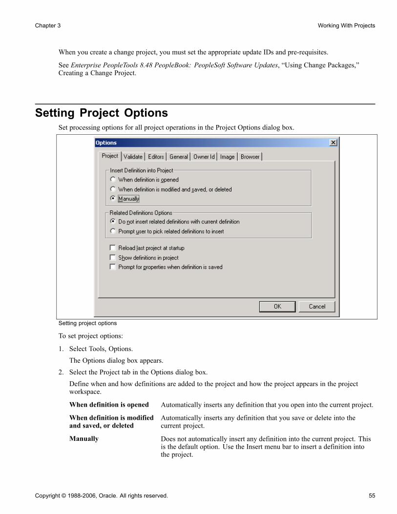
Chapter 3 Working With Projects
When you create a change project, you must set the appropriate update IDs and pre-requisites.
See Enterprise PeopleTools 8.48 PeopleBook: PeopleSoft Software Updates, “Using Change Packages,”Creating a Change Project.
Setting Project OptionsSet processing options for all project operations in the Project Options dialog box.
Setting project options
To set project options:
1. Select Tools, Options.The Options dialog box appears.
2. Select the Project tab in the Options dialog box.Define when and how definitions are added to the project and how the project appears in the projectworkspace.
When definition is opened Automatically inserts any definition that you open into the current project.
When definition is modifiedand saved, or deleted
Automatically inserts any definition that you save or delete into thecurrent project.
Manually Does not automatically insert any definition into the current project. Thisis the default option. Use the Insert menu bar to insert a definition intothe project.
Copyright © 1988-2006, Oracle. All rights reserved. 55
Working With Projects Chapter 3
Do not insert relateddefinitions with currentdefinition
Does not prompt you to include related definitions. Only the specifieddefinition is inserted, not related definitions.
Prompt user to pick relateddefinitions to insert
After you select Insert, Current Definition into Project, a dialog boxappears, prompting you to pick which related definitions to insert.
Reload last project atstartup
When starting PeopleSoft Application Designer, the project that was lastopened in the previous session opens automatically.
Show definitions in project Displays a black mark next to icons for definitions that are explicitly ina project (Development view) to indicate that they are in the project.Attribute definitions, which are not explicitly part of the project, arenot marked.
Prompt for propertieswhen definition is saved
Prompts you with a definition properties dialog box before you cansave the definition.
Validating ProjectsAn important part of the PeopleSoft upgrade process involves validating your upgrade project. PeopleSoftApplication Designer includes a validate utility to make sure that all definitions included in the projectactually exist in your database.
To validate a project:
1. Close all active component definitions in the definition workspace.Otherwise, the validation occurs in the component, rather than the project.
2. Select Tools, Options.3. Select the Validate tab in the Options dialog box.4. Select Validate project integrity.5. Click OK.6. Select Tools, Validate Project.
The validate utility runs a series of tests on the project or components and sends its results to the Validate tabin the output window. If errors are found, they are listed on this tab.
Note. The Validate WSRP compliance option applies to projects that contain PeopleSoft content intendedfor WSRP production.
See Enterprise PeopleTools 8.48 PeopleBook: Internet Technology, “Using WSRP to Consume and ProduceRemote Portlets,” Validating WSRP-Compliance.
56 Copyright © 1988-2006, Oracle. All rights reserved.

Chapter 3 Working With Projects
Setting System IDsThe system ID functionality makes system ID maintenance easier for developers. This is especially true forthose working on mobile applications where the System ID field must be set to SYNCID on the recordproperties for each record of each component used in mobile applications.
You can set the system ID for an overall project or for the current record definition in the project workspace.
To set system IDs for a project:
1. Open the project.2. Select Build, Set System IDs for ProjectThe Build Progress dialog box appears, displaying the progress of the command for the number of objectsaffected by this command.
See AlsoEnterprise PeopleTools 8.48 PeopleBook: PeopleSoft Mobile Agent, “Using Synchronizable ComponentInterfaces,” Understanding the Synchronization ID and Datetime Stamp
Copyright © 1988-2006, Oracle. All rights reserved. 57

Working With Projects Chapter 3
58 Copyright © 1988-2006, Oracle. All rights reserved.

CHAPTER 4
Creating Field Definitions
This chapter provides an overview of field definitions and discusses how to:
• Create new field definitions.• Use multiple labels.• Open an existing field definition.• View field properties.• Change field definitions.• Set custom field formats.• Use the translate table.
Understanding Field DefinitionsFields are the basic building blocks in your PeopleSoft system; in database terms, they represent columns in atable or view. Field definitions are stand-alone development definitions, defined in PeopleSoft ApplicationDesigner, and can be shared across multiple record definitions. Changes to field properties affect all recordsthat include that field.
Each field definition includes attributes, such as data type, field name, long name, short name, field length,and various formatting values.
Fields in Record DefinitionsBy grouping fields that share a common theme, you build a record definition. For example, a department table(record) might include a department ID field, department name field, location field, and so on.
For each field definition that you add to a record, you define additional characteristics, called record fieldproperties, that are specific to the way the field is used in that particular record. Record field properties are notshared with other records in which the field is used.
Creating New Field DefinitionsThis section assumes that you are already familiar with the general terminology and functions of PeopleSoftApplication Designer.
This section discusses how to:
• Create a new field definition.
Copyright © 1988-2006, Oracle. All rights reserved. 59
Creating Field Definitions Chapter 4
• Specify attributes for a new field definition.• Specify character field attributes.• Specify long character field attributes.• Specify number field attributes.• Specify date field attributes.• Specify time field attributes.• Specify DateTime field attributes.• Specify image field attributes.• Specify ImageReference field attributes.
Creating a New Field DefinitionTo create a new field definition:
1. Click the New button on the PeopleSoft Application Designer toolbar.
The New dialog box appears.
2. Select Field.3. Click OK.A new character field opens in the workspace area.
4. Select one of the following field types from the Field Type drop-down list box.
Note. Make sure to name your fields according to the accepted naming conventions.
See Chapter 2, “Using PeopleSoft Application Designer,” Saving Definitions, page 29.
Character (Char) Alphanumeric field of fixed length.
Long Character (Long) Alphanumeric field of variable length used for textual entries, such ascomments or descriptions.
Number (Nbr) Positive numeric field of fixed length for which decimals are allowed.
Signed Number (Sign) Positive or negative numeric field of fixed length for which decimalsare allowed.
Date (Date) Date field of constant length. The system edits dates and prohibits incorrectones, such as day 42 or month 20. Date fields always store a four-digit year.
Time (Time) Time field of a constant length. Built-in edits prohibit impossible times,such as hour 26, minute 70, or second 94.
DateTime (DtTm) Date and time field of constant length. Built-in edits prohibit impossibledates and times, as defined in the individual Date and Time fields.DateTime fields always store a four-digit year.
Image (Img) Image field to store images in a user-defined format, such as JPEG or GIF.
ImageReference (Iref) Use this to change an image dynamically at runtime using PeopleCode.
60 Copyright © 1988-2006, Oracle. All rights reserved.
Chapter 4 Creating Field Definitions
Attachment (Att) Maps to a BLOB database type to hold the contents of a file attachment.However, PeopleSoft recommends using the existing field, FILE_DATA,if a BLOB column is needed. For attachments, use the subrecordATTACH_DETAIL, which contains FILE_DATA.
After you select a field type, the definition workspace displays a field definition window in which youspecify attributes to complete your new field definition.
Specifying Attributes for a New Field DefinitionAccess the field definition window for the new field definition.
The following property settings are shared by all field types.
Note. Multiple views of this dialog box are available, depending on which field type you select. PeopleSoftdocuments fields that are common to all views first.
Label ID Enter a unique identifier for the field that is less than 18 characters, withoutspaces, and in uppercase. Make this the default label by selecting the Defcheck box in the last column; otherwise, the first label is the default. You canset only one field label as the default.
Note. You can specify multiple labels for one field and change them atruntime using PeopleCode.
See Chapter 4, “Creating Field Definitions,” Using Multiple Labels, page 69.
Long Name Enter up to 30 characters. The name that you enter here appears as the RFTLong option for a page field. This label is also used for the tool tip, or hovertext, for links at runtime if it is different from the assigned display value ofthe link.
Short Name Enter up to 15 characters as an alternate name to use on pages and reportsif you have insufficient space to display the long name. If you leave thisfield blank, the system automatically copies the first 15 characters of thelong name into this field. The name that you enter here appears as the RFTShort option for a page field.
Note. If you name the field the same as the default label ID, you can identify itmore easily when using PeopleCode.
Def (default) When you enter the first label ID, the system automatically selects the Defcheck box. The system uses this default field if you have multiple labels.You can have only one default field.
Not Used This check box is always read-only in the field definition properties dialogbox. You can change its value using PeopleCode, causing the field to be:
• Skipped as part of the unique index.• Exposed to PeopleCode for read and write operations.• Ignored in Query.• Ignored in nVision.
Copyright © 1988-2006, Oracle. All rights reserved. 61
Creating Field Definitions Chapter 4
• Unavailable to users in search pages or list boxes if it is a search key orlist box item.
See Enterprise PeopleTools 8.48 PeopleBook: PeopleCode LanguageReference, “PeopleCode Built-in Functions,” SetDBFieldNotUsed.
Chart Field Read-only in the field definition properties dialog box. It is used for characterfields and by financial applications to specify a usage pattern. You can changethe value using PeopleCode.
Specifying Character Field AttributesCharacter fields are used for names, codes, and anything with letter values. You also use them for numbersfor which you want to contain formatting attributes and the data itself. Examples of such fields are those inwhich you enter telephone numbers and zip or postal codes. You cannot use character fields in calculations.You can enter decimal numbers in character fields, but you cannot use them mathematically until you convertthem back to numeric fields.
You can specify character field attributes at design time, and you can access most of them at runtime withPeopleCode.
Field Length Enter a whole number between 1 and 254 for the length of the field.
Format Type Select one of the following values:Uppercase: Converts the field value to uppercase and signifies that no otherformatting options apply to this field. Use this option for code values, such asdepartment ID, for which it doesn’t matter whether the user enters the value inuppercase or lowercase. This is the default format.Mixedcase: Stores uppercase and lowercase characters as entered. Use thisoption for fields that contain textual data, such as a department or companydivision name. For example, Accounting − Receivables is more readable thanACCOUNTING − RECEIVABLES.Numbers Only: Forces entries to be numeric. This is useful for enforcingnumeric values without redefining the field as a number field. This optionautomatically populates fields with leading zeros. For example, if the userenters 1 in a three-digit field, the system changes this to 001.SSN: Formats the entry in U.S. Social Security Number format (999-99-9999).Define 9 as the field length, even though the display length is 11. The systemautomatically adds dashes when formatting the field for display, but thenumber is stored in the database without the dashes.SIN: Formats the entry in Canadian Social Insurance Number format(999-999-999) and performs the standard check-digit verification for SIN.Define 9 as the field length, even though the display length is 11. The systemautomatically adds dashes when formatting the field for display, but thenumber is stored in the database without the dashes.Raw Binary: Allows character fields containing embedded NULLs, such asencrypted values.Name: Requires that the field entry appear in the PeopleSoft standardname format:[lastname] [suffix],[prefix] [firstname] [middle name/initial]
62 Copyright © 1988-2006, Oracle. All rights reserved.

Chapter 4 Creating Field Definitions
The entry can contain alphabetic characters, spaces, periods, hyphens, andapostrophes. Uppercase and lowercase characters are preserved as entered—inother words, mixed case formatting is included automatically. Valid entriesmight include:
• O’Brien,Michael.
• Jones IV,James.
• Phillips MD,Deanna Lynn.
• Reynolds Jr.,Dr. John Q.
• Phipps-Scott,Adrienne.
• Knauft,Günter.
Note. If the name contains Japanese characters, the first and last names mustbe separated by a space instead of a comma. The Japanese name format cancontain hankaku katakana, Zenchiku katakana, hiragana, kanji, and romajicharacters. It can also include spaces, periods, and hyphens.
Postal Code North America: Formats the entry to U.S. zip code format orCanadian postal code format. Canadian postal codes are edited to ensure thatalpha and numeric characters are entered in the correct positions.The following entry formats apply. Stored formats appear in parenthesesfollowing the entry format:
• 99999 (99999)
• 99999-9999 (99999-9999)
• 999999999 (99999-9999)
• A9A9A9 (A9A 9A9)
• A9A 9A9 (A9A 9A9)
Postal Code International: Allows the entry of international postal codes. Thefield length must be at least 7 digits. If 9 digits are entered, the system assumesthat the value is a U.S. zip code; if the entry is in A9A9A9 format, the systemassumes that the value is a Canadian postal code. Then, the value is formattedaccordingly. For all other entries, no formatting is applied.
Phone Num North America (phone number North America): Formats the entryin North American telephone number format.
The following entry formats apply. Stored formats appear in parenthesesfollowing the entry format:
• 9999999 (999-9999)• 999-9999 (999-9999)• 9999999999 (999/999-9999)• 999/999-9999 (999/999-9999)Phone Number International: Allows the entry of international telephonenumbers. If you enter 7 or 10 digits (and no other characters), the systemassumes that the value is a North American phone number, and formats itaccordingly. For all other entries, no formatting is applied.
Copyright © 1988-2006, Oracle. All rights reserved. 63
Creating Field Definitions Chapter 4
Custom: If you select this value, the Family Name and Display Name fieldsbecome available for entry. These selections enable you to apply additionalformatting attributes that affect how the field appears on a page.
Specifying Long Character Field AttributesDepending on your database environment, the maximum length of a long character field ranges from severalthousand characters to 32,767 characters (64,000 bytes). Using a long character field instead of a regularcharacter field enables the user to insert a tab at runtime by pressing CTRL+TAB.
Maximum Length To control the length of a long character field, enter the maximum number ofbytes that you want the system to write to this field. If you don’t specify amaximum length, or specify 0 (zero), you can enter an unlimited number ofcharacters, depending on the capacity of your database system.When working with fields, be aware that your chosen database system limitsthe amount of data contained in a field. For Oracle the field size is truncated to1333 characters. Consider this limitation when choosing to use fields of aLong Character data type.For Oracle, if the maximum length of a long field is less than 4001 bytes,the field can be stored more efficiently as a VARCHAR2(4000). To supportPeopleSoft’s Unicode implementation on the Oracle platform, PeopleSoftdefined "long" columns with a specified length of 1330 or less as VARCHAR2columns. If the length specified was greater than 1330, the column wasgenerated as a long VARCHAR or long raw, depending on the setting of theRaw Binary check box. This allows for the maximum possible usage of atripled VARCHAR2 character length for Unicode-defined databases.
Raw Binary Select to store data that is not converted when moving data between differentsystems. Raw binary is intended for binary data and byte strings. For example,raw binary can store graphics, sound, documents, and arrays of binary data.
Specifying Number Field AttributesWhen you create a new field, notice that there are two field types for numbers:
• Number fields.• Signed number fields.
Both field types are fixed in field length and allow the entry of positive numbers. Only signed numbers,however, allow the entry of negative numbers. Otherwise, both number field types are the same.
Unlike character fields, a number field can contain decimals but does not contain special formatting, such asthe formatting for telephone numbers. Use number fields for calculations. If you use number fields for codes,you sacrifice flexibility to change your coding structure to alphanumeric in the future.
64 Copyright © 1988-2006, Oracle. All rights reserved.

Chapter 4 Creating Field Definitions
Number Field type
Integer Positions Specify the number of integer positions to the left of the decimal. If thenumber contains only decimal positions, leave this field blank.
Decimal Positions Specify the number of decimal positions to the right of the decimal. If a numbercontains only integer positions, leave this field blank. In calculations, thesystem rounds up the result to the number of decimal positions defined here.
Note. Number fields cannot exceed 31 positions. Therefore, the sum of integerand decimal positions cannot exceed 31.
The field length notation differs between PeopleSoft Application Designer andStructured Query Language (SQL). If you specify a field length of 8 integerpositions and 3 decimal positions in PeopleSoft Application Designer, SQLprocesses that as a length notation of 11.3.
SQL describes field length in terms of precision and scale. Precision is thetotal number of integer and decimal positions. Scale is the number of decimalpositions. Thus, 11.3 means 8 integer positions and 3 decimal positions; 11.0means 11 integer positions and 0 decimal positions.When you enter 0 in the Decimal Positions field and enter 5 or 10 in theInteger Positions field, the RawBinary format option appears. The RawBinaryformat converts a number field value to a full-length 16- or 32-bit integer.See the example in the table below.
Signed Select this check box for a field that is used for arithmetic calculations thatmight contain a negative value.
This table shows how the integer position affects the RawBinary storage format:
Copyright © 1988-2006, Oracle. All rights reserved. 65

Creating Field Definitions Chapter 4
Integer Position Maximum Value Number Stored As
5 65535 16-bit integer
10 4294967295 32-bit integer
Specifying Date Field AttributesDate fields contain calendar dates. A date field has a field length of 10 and is maintained by the system. Thedefault format of a date field is defined by the database and can be overridden by your browser settings.
Default to 2000 if year lessthan or equal to
Specify the last two digits of a year, which is typically what users enter in adate field. If you enter 50, the default century becomes 2000 when someoneenters 0 through 50 as the year in a date field. If someone enters a numberbetween 51 and 99 in a date field, the default century becomes 1900. Thedefault value is 50.
Note. When working with date and time fields on pages and search pages, carefully consider search criteria.Assume the date, time, and time zone fields are separate with the condition that the time is time zone-controlledby the time zone field and the time is associated with the date field. In this case, you need to provide date, timeand time zone on the search page if any one of those search criteria is required.
Specifying Time Field AttributesTime fields are fixed-length fields (15 positions, format of HH:MI:SS.999999) that contain the time of day.The maximum time precision varies, depending on your database.
Time Formatting Specify the formatting for this field. HH represents hours, MI representsminutes, SS represents seconds, and 999999 represents microseconds.
Note. You can use %CLIENTDATE as the default constant for the Time field. %CLIENTDATE adjusts thedate as appropriate to the time zone of the browser.
See AlsoEnterprise PeopleTools 8.48 PeopleBook: PeopleCode Language Reference, “System Variables,” %ClientDate
Enterprise PeopleTools 8.48 PeopleBook: PeopleCode Language Reference, “System Variables,” %Date
Specifying DateTime Field AttributesThe DateTime field is a fixed-length field (26 positions, format of YYY-MM-DD-HH-MI-SS.999999) thatholds dates and times. The maximum date and time precision depends on your database.
Note. You can use %CLIENTDATE as the default constant for the DateTime field. %CLIENTDATE adjuststhe date as appropriate to the time zone of the browser.
66 Copyright © 1988-2006, Oracle. All rights reserved.
Chapter 4 Creating Field Definitions
See AlsoEnterprise PeopleTools 8.48 PeopleBook: PeopleCode Language Reference, “System Variables,” %ClientDate
Enterprise PeopleTools 8.48 PeopleBook: PeopleCode Language Reference, “System Variables,” %Date
Specifying Image Field AttributesUse Image fields to store application data that takes the form of images. Image fields are functionally nodifferent from any other type of field. Just as end-users employ character fields to store names and addresses,they can employ image fields to keep track of all types of digital pictures. This field enables you to storepictures of assets, company logos (in SQL tables), or scanned images of employees (as part of their personaldata rows).
Maximum Length Specify the maximum number of bytes available to store an image. If youdon’t specify a maximum length, the maximum length is determined by yourdatabase platform. If a user attempts to cut and paste an image that is largerthan the maximum length or database capacity, an error message appears.The following databases apply (maximum length appears in parentheses):
• DB2/zOS (up to 32 kilobytes*).• Oracle (2 gigabytes).• Sybase (2 gigabytes).• SQL Server (2 gigabytes).• Informix (2 gigabytes).• DB2 UDB for Linux, Unix, and Windows (32 kilobytes).* Depends on the page size, the buffer pool, and the other data that is beingstored in that row.
Image Format Select an image format. Format determines the type of image that you canselect and write to the database for this field. PeopleSoft supports BMP, DIB,GIF, CUT, EPS, JPG, PCX, PCT, RLE, and TGA image types. At runtime, theuser can upload BMP, DIB, GIF, and JPG images to the database.
Specifying ImageReference Field AttributesUse the ImageReference field to store static images that can be changed at runtime with PeopleCode. Byassociating image definitions with an ImageReference field on a page, you can display images dynamically.For example, to have different images appear on an employee profile depending on the status of theemployee’s current review, use the ImageReference field to reference the current review field and displaythe appropriate image.
Working With Additional Oracle Data Type MappingsIf your site has upgraded to a PeopleSoft 9 application and performed the appropriate conversion processduring the application upgrade, there are different data type mappings between PeopleSoft field types andthe underlying Oracle system.
See The upgrade documentation and release notes for your release for information regarding the conversionprocess.
Copyright © 1988-2006, Oracle. All rights reserved. 67

Creating Field Definitions Chapter 4
The following table describes how the PeopleSoft field types involved map to the underlying Oracle data types.
PeopleSoft Field TypePre Conversion Oracle Data
Type MappingPost Conversion Oracle Data
Type Mapping
Character ANSI:VARCHAR2(n)
Unicode:VARCHAR2(n*3)
ANSI:VARCHAR2(n)
Unicode:VARCHAR2(n)
Note. For Unicode the VARCHAR2column is interpreted as thenumber of Unicode charactersdue to init.ora parameterNLS_LENGTH_SEMANTICS isset to "CHAR".
Long Character If 1 <= n <= 2000
ANSI:VARCHAR2
Unicode:VARCHAR2(n*3) CHECK(Length <field name>) <=n)
If n = 0 or n > 2000
ANSI: LONGVARCHAR
Unicode:LONGVARCHAR
ANSI:
VARCHAR2(n) when 1 <= n <= 4000
CLOB when n = 0, or n > 4000
Unicode:
VARCHAR2(n) when 1 <= n <= 1333
CLOB when n = 0, or n > 1333
Note. For Unicode the VARCHAR2column is interpreted as thenumber of Unicode charactersdue to init.ora parameterNLS_LENGTH_SEMANTICS isset to "CHAR".
Long Character with Raw Binaryattribute
ANSI: LONG RAW
Unicode:LONGRAW
ANSI: BLOB
Unicode:BLOB
Image ANSI: LONG RAW
Unicode:LONGRAW
ANSI: BLOB
Unicode:BLOB
Attachment ANSI: LONG RAW
Unicode:LONGRAW
ANSI: BLOB
Unicode:BLOB
Working With Additional Microsoft SQL Server2005 Data Type MappingsIf your site has upgraded to a PeopleSoft 9 application and performed the appropriate conversion processduring the application upgrade, there are different data type mappings between PeopleSoft field types andthe underlying Microsoft SQL Server 2005 system.
See The upgrade documentation and release notes for your release for information regarding the conversionprocess.
The following table describes how the PeopleSoft field types involved map to the underlying MicrosoftSQL Server data types.
68 Copyright © 1988-2006, Oracle. All rights reserved.
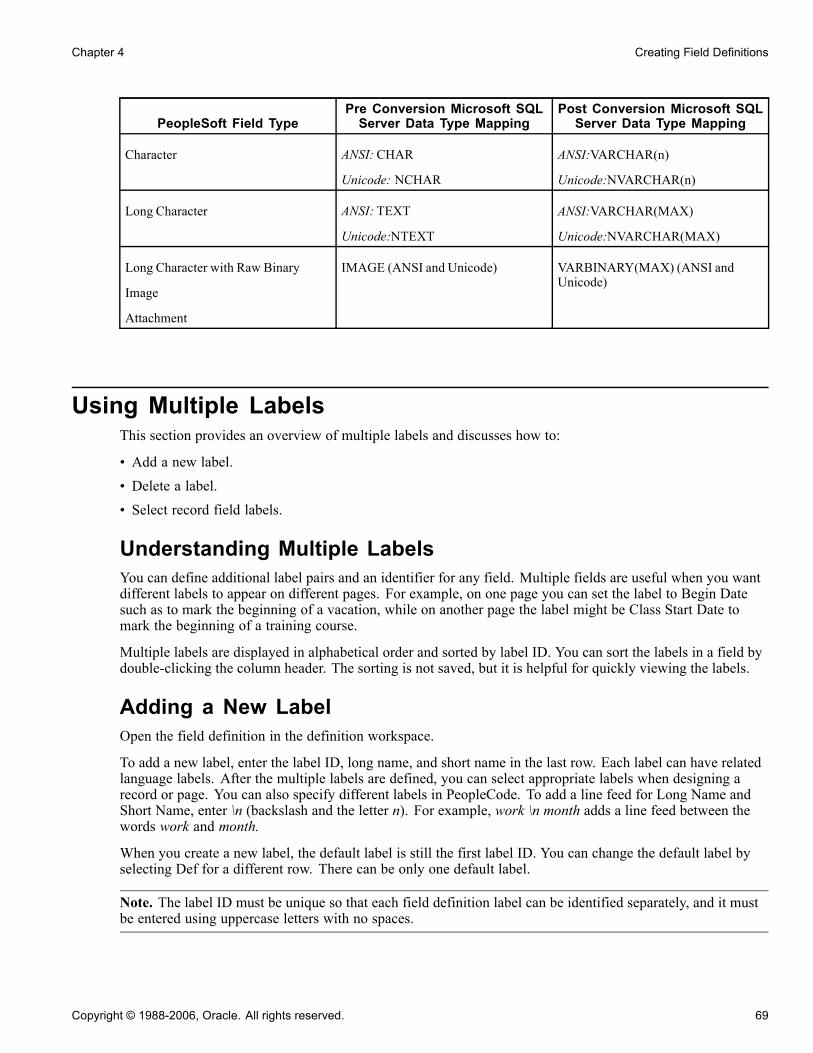
Chapter 4 Creating Field Definitions
PeopleSoft Field TypePre Conversion Microsoft SQLServer Data Type Mapping
Post Conversion Microsoft SQLServer Data Type Mapping
Character ANSI: CHAR
Unicode: NCHAR
ANSI:VARCHAR(n)
Unicode:NVARCHAR(n)
Long Character ANSI: TEXT
Unicode:NTEXT
ANSI:VARCHAR(MAX)
Unicode:NVARCHAR(MAX)
Long Character with Raw Binary
Image
Attachment
IMAGE (ANSI and Unicode) VARBINARY(MAX) (ANSI andUnicode)
Using Multiple LabelsThis section provides an overview of multiple labels and discusses how to:
• Add a new label.
• Delete a label.
• Select record field labels.
Understanding Multiple LabelsYou can define additional label pairs and an identifier for any field. Multiple fields are useful when you wantdifferent labels to appear on different pages. For example, on one page you can set the label to Begin Datesuch as to mark the beginning of a vacation, while on another page the label might be Class Start Date tomark the beginning of a training course.
Multiple labels are displayed in alphabetical order and sorted by label ID. You can sort the labels in a field bydouble-clicking the column header. The sorting is not saved, but it is helpful for quickly viewing the labels.
Adding a New LabelOpen the field definition in the definition workspace.
To add a new label, enter the label ID, long name, and short name in the last row. Each label can have relatedlanguage labels. After the multiple labels are defined, you can select appropriate labels when designing arecord or page. You can also specify different labels in PeopleCode. To add a line feed for Long Name andShort Name, enter \n (backslash and the letter n). For example, work \n month adds a line feed between thewords work and month.
When you create a new label, the default label is still the first label ID. You can change the default label byselecting Def for a different row. There can be only one default label.
Note. The label ID must be unique so that each field definition label can be identified separately, and it mustbe entered using uppercase letters with no spaces.
Copyright © 1988-2006, Oracle. All rights reserved. 69

Creating Field Definitions Chapter 4
Deleting a LabelOpen the field definition in the definition workspace.
To delete a label, right-click a field label row and select Delete Label from the pop-up menu. Labels that arecurrently in use cannot be deleted. To determine where the label is used, select the label and select FindDefinition Reference from the pop-up menu. The results appear in the Find Definition Reference outputwindow.
Selecting Record Field LabelsAccess the Record Field Properties dialog box.
Record Field label ID drop-down list box
70 Copyright © 1988-2006, Oracle. All rights reserved.
Chapter 4 Creating Field Definitions
For the record definition, the Record Field label ID drop-down list box is available on the Use tab of theRecord Field Properties dialog box. The drop-down list box displays the label ID, short name, and long namethat you set in the field definition. *** Use Default Label *** is the default selection. The record field labelchanges automatically whenever you change the default label in the field definition.
Opening an Existing Field DefinitionThere are several ways to open a field definition:
• Select File, Open from the menu.
From this dialog box, you can view all available fields in the database. You can open all fields of a certaintype or from a specific project, or you can open a specific field or set of fields.
• Clone an existing definition.
To create a field definition with attributes similar to an existing one:
1. Open an existing field definition.
2. Select File, Save As.
3. Enter a new name.
• Open the field from the project workspace.
Double-click a field from the project workspace to open a field definition window in the definitionworkspace.
• Open the field from the record.
Open an existing record definition. When the record definition window opens, you can:
1. Select a field.
2. Right-click.
3. Select View Definition.
Viewing Field PropertiesThere are several ways to view field properties:
• While in the field definition workspace, click the Properties button.• Select File, Definition Properties.• While in a record definition:
1. Select the field.2. Right-click the field name.3. Select View Field Properties from the pop-up menu.
Copyright © 1988-2006, Oracle. All rights reserved. 71
Creating Field Definitions Chapter 4
The General tab in the Field Properties dialog box provides a place for you to enter comments documenting thepurpose of the field definition. The Owner ID drop-down list box enables you to select a valid owner, as inapplication project or role. The Last Updated group box contains information—date, time, and user ID—aboutthe last time that the field definition was modified.
The Translate Values tab is available only for character fields.
See AlsoChapter 4, “Creating Field Definitions,” Using the Translate Table, page 84
Changing Field DefinitionsThis section provides an overview of the effects of changing field definitions and discusses how to:
• Change field types.
• Rename field definitions.
• Delete field definitions.
• Print field definitions.
Understanding the Effects of Changing Field DefinitionsWhen you develop new record definitions or modify existing ones, you might need to change characteristicsor attributes for a field. If you change attributes in a field definition, the change affects every occurrence ofthe field in every record definition. So, before you change basic attributes in a field definition, consider howit affects all of the record definitions in which the field occurs. If the change isn’t appropriate for everyoccurrence of this field, consider defining a new field instead.
If you still find that a change is needed, PeopleSoft recommends that you determine the extent of the changeby finding out how many records are affected. Do this by using the Find Definition References tool. Openthe field definition and select Edit, Find Definition References, or right-click and select the option from thepop-up menu. If you’re in a record definition window, another method is to select the field, right-click the fieldname, and select Find Definition References-Field from the pop-up menu.
The Find Definition References tab in the Output window displays a list of all record definitions, pagedefinitions, messages, channels, file layouts, and PeopleCode programs in which the field is used. Double-clicka line of output to open the corresponding definition in the definition workspace.
Note. Changing the name or length in a field definition requires modification of the underlying SQL table. Dothis either by running the build process and specifying Create Tables or Alter Tables, or by carrying out anaction issued by your system administrator. For example, if you change the length in a field definition and 30record definitions contain the same field name, you have 30 records that must be created or altered.
Changing Field TypesChange a field type by opening a field and selecting another field type from the drop-down list box. However,this feature is intended as a design-time change—that is, before your tables have been created in the database.While some field type conversion can be done, results vary, depending on your database platform.
72 Copyright © 1988-2006, Oracle. All rights reserved.

Chapter 4 Creating Field Definitions
Note. If you change a field from one type to another, all records containing that field must be rebuilt byrunning the Alter process. Use Find Definition References to find all incidences of the changed field.
See Chapter 7, “Administering Data,” Altering Tables, page 161.
Renaming Field DefinitionsYou can use either the Rename Definition dialog box or the Open Definition dialog box to rename a fielddefinition.
Using the Rename Definition Dialog BoxTo rename a field definition from the Rename Definition dialog box:
1. Select File, Rename to open the Rename Definition dialog box.2. Select Field as the definition type.3. Enter the name of the field.If you aren’t sure of the name or the correct spelling, use the search criteria fields to locate the field torename. The list displays field names that match your search criteria.
4. To rename a field in the list, select the field and click Rename, or double-click the field.The field name becomes available for entry, and you can type the new name.
5. When you finish typing the new name, press ENTER or click the Rename button.The Rename Field dialog box appears. Select the records in which you want the field to be renamed.The De-select All button toggles to Select All.
6. Click OK.
Using the Open Definition Dialog BoxTo rename a field definition from the Open Definition dialog box:
1. Select File, Open to access the Open Definition dialog box.This dialog box enables you to set up search criteria for locating field names.
2. Select Field as the definition type.If you have additional information, use the Name field. You can further narrow your search criteria byselecting a field type or the name of the project that contains the field to delete.
3. Click the Open button or press ENTER when you have completed your search criteria.4. You can rename a field in the Open Definition dialog box by selecting the field, right-clicking the fieldname, and selecting Rename.You can also select the field name and click it a second time. The field name becomes available forentry and you can enter a new name.
5. When you finish typing the new name, press ENTER or click the Rename button.
Results of Renaming Field DefinitionsWhen you rename a field, the system automatically changes all occurrences of it, including data on tables withcolumns named FIELDNAME where the data matches the field being renamed.
Copyright © 1988-2006, Oracle. All rights reserved. 73

Creating Field Definitions Chapter 4
The only references that are not renamed are the text portions of SQL functions, such as SQLExec and ScrollSelect. If you have already used SQL Create to create the underlying tables for the record definitions thatcontain the field that you renamed, you must re-create or alter those tables. If the tables contain data that youwant to preserve, use the SQL Alter function to rename the database table fields.
Deleting Field DefinitionsYou can use either the Delete Definition dialog box or the Open Definition dialog box to delete a fielddefinition.
Using the Delete Definition Dialog BoxTo delete field definitions by using the Delete Definition dialog box:
1. Select File, Delete to open the Delete Definition dialog box.Set up search criteria for locating field names.
2. Select Field as the definition type.3. If you have additional information, use the Name field.4. Select a field type or the name of the project that contains the field that you want to delete.This further narrows your search criteria.
5. When your search results appear in the output window, delete the field definition by selecting the field andclicking the Delete button or double-clicking the field name.
Note. You cannot delete a field that is currently used in any records. Before you delete a field definition, youmust first remove it from records in which it appears.
Using the Open Definition Dialog BoxTo delete field definitions by using the Open Definition dialog box:
1. Select File, Open to access the Open Definition dialog box.
This dialog box enables you to set up search criteria for locating field names.
2. Select Field as the definition type.
3. If you have additional information, enter it in the Name field.
4. You can further narrow your search criteria by selecting a field type or the name of the project that containsthe field that you want to delete.
5. When you have completed your search criteria, click Open or press ENTER.
6. Right-click the field that you want to delete from the list of field names displayed.
7. Select Delete from the pop-up menu.
Printing Field DefinitionsIf you plan to make changes to your field definitions, PeopleSoft recommends viewing your field definitionbefore you proceed. You can view it on your screen or print it to a one-page report that combines informationfrom several resources. This can also serve as a paper audit trail to document your database.
74 Copyright © 1988-2006, Oracle. All rights reserved.

Chapter 4 Creating Field Definitions
To print a field definition, select File, Print from the field definition window (or click the Print button in thetoolbar) to open the Print dialog box, where you specify printing options. You can also print field definitionsfrom the Open Definition dialog box. On the list resulting from your search, right-click the name of the fielddefinition that you want to print, and select Print from the pop-up menu to view your printing options.
Setting Custom Field FormatsThis section provides overviews of custom field formats and format notation and discusses how to:
• Change format families.
• Edit formats.
• Use family options.
• Test formats.
Understanding Custom Field FormatsPeopleTools has formatting provisions at both the field and page levels. The field format specifications affectinternal values that are stored in the database, and the page formats affect the visual presentation of values.
There are several formatting options for U.S. Social Security Numbers, Canadian Social Insurance Numbers,postal codes, telephone numbers, and various currencies, dates, and times. Custom field formats extend theseformatting provisions to support the same types of data in other countries. They also support other types offormatted information, such as bank codes, credit card numbers, part numbers, or serial numbers.
Understanding Format NotationStored and display formats are defined by strings that contain lexical, literal, and meta characters:
• Lexical characters delimit character expressions and designate interpretation rules.• Literal characters represent only themselves.• Meta characters represent a class of characters.
Use the format symbols in the following tables to create the format notation for your own custom field formats:
Copyright © 1988-2006, Oracle. All rights reserved. 75

Creating Field Definitions Chapter 4
Meta Symbol Description
# Digit placeholder.
If the number has more digits to the right of the decimal point than there are # symbolsto the right in the format, the system truncates the number to as many decimal places asthere are # symbols to the right.
If the number has more digits to the left of the decimal point than there are # symbols tothe left in the format, the system displays the extra digits.
If the number has fewer digits to the right of the decimal point than there are # symbols tothe right of the decimal point in the format, the system adds spaces.
If the number has fewer digits to the left of the decimal point than # symbols to the left ofthe decimal point in the format, the system also adds spaces.
Example format: ###.##
Input: 1234.567 - Matches? Yes - Output: 1234.56
0 (zero) Digit placeholder.
Follows the same rules as for #, except that if the number has fewer digits than there are 0sin the format, the system displays the extra 0s.
Example format: 000.00
Input: 1.2345 - Matches? Yes - Output: 001.23
(period) Decimal point.
This symbol determines howmany digits (0 or #) appear to the right and left of the decimalpoint.
If the format contains only # symbols to the left of this symbol, numbers less than oneappear with a decimal point.
This symbol has meaning only in conjunction with the # and 0 symbols.
Example format: ###.##
Input: .12345 -Matches? Yes - Output: .12
9 Required numeric placeholder.
If the number does not have the same number of digits as there are 9s, the system displaysan error message.
Example format: 999
Input: 123 - Matches? Yes - Output: 123
Input: 12 - Matches? No
76 Copyright © 1988-2006, Oracle. All rights reserved.
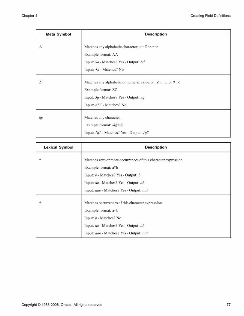
Chapter 4 Creating Field Definitions
Meta Symbol Description
A Matches any alphabetic character: A−Z or a−z.
Example format: AA
Input: Sd - Matches? Yes - Output: Sd
Input: 4A - Matches? No
Z Matches any alphabetic or numeric value: A−Z, a−z, or 0−9.
Example format: ZZ
Input: 3g - Matches? Yes - Output: 3g
Input: A3C - Matches? No
@ Matches any character.
Example format: @@@
Input: 1q? - Matches? Yes - Output: 1q?
Lexical Symbol Description
* Matches zero or more occurrences of this character expression.
Example format: a*b
Input: b - Matches? Yes - Output: b
Input: ab - Matches? Yes - Output: ab
Input: aab - Matches? Yes - Output: aab
+ Matches occurrences of this character expression.
Example format: a+b
Input: b - Matches? No
Input: ab - Matches? Yes - Output: ab
Input: aab - Matches? Yes - Output: aab
Copyright © 1988-2006, Oracle. All rights reserved. 77
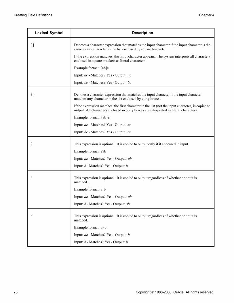
Creating Field Definitions Chapter 4
Lexical Symbol Description
[ ] Denotes a character expression that matches the input character if the input character is thesame as any character in the list enclosed by square brackets.
If the expression matches, the input character appears. The system interprets all charactersenclosed in square brackets as literal characters.
Example format: [ab]c
Input: ac - Matches? Yes - Output: ac
Input: bc - Matches? Yes - Output: bc
{ } Denotes a character expression that matches the input character if the input charactermatches any character in the list enclosed by curly braces.
If the expression matches, the first character in the list (not the input character) is copied tooutput. All characters enclosed in curly braces are interpreted as literal characters.
Example format: {ab}c
Input: ac - Matches? Yes - Output: ac
Input: bc - Matches? Yes - Output: ac
? This expression is optional. It is copied to output only if it appeared in input.
Example format: a?b
Input: ab - Matches? Yes - Output: ab
Input: b - Matches? Yes - Output: b
! This expression is optional. It is copied to output regardless of whether or not it ismatched.
Example format: a!b
Input: ab - Matches? Yes - Output: ab
Input: b - Matches? Yes - Output: ab
~ This expression is optional. It is copied to output regardless of whether or not it ismatched.
Example format: a~b
Input: ab - Matches? Yes - Output: b
Input: b - Matches? Yes - Output: b
78 Copyright © 1988-2006, Oracle. All rights reserved.
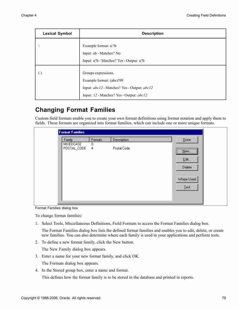
Chapter 4 Creating Field Definitions
Lexical Symbol Description
\ Example format: a\?b
Input: ab - Matches? No
Input: a?b - Matches? Yes - Output: a?b
( ) Groups expressions.
Example format: (abc)!99
Input: abc12 - Matches? Yes - Output: abc12
Input: 12 - Matches? Yes - Output: abc12
Changing Format FamiliesCustom field formats enable you to create your own format definitions using format notation and apply them tofields. These formats are organized into format families, which can include one or more unique formats.
Format Families dialog box
To change format families:
1. Select Tools, Miscellaneous Definitions, Field Formats to access the Format Families dialog box.The Format Families dialog box lists the defined format families and enables you to edit, delete, or createnew families. You can also determine where each family is used in your applications and perform tests.
2. To define a new format family, click the New button.The New Family dialog box appears.
3. Enter a name for your new format family, and click OK.The Formats dialog box appears.
4. In the Stored group box, enter a name and format.This defines how the format family is to be stored in the database and printed in reports.
Copyright © 1988-2006, Oracle. All rights reserved. 79
Creating Field Definitions Chapter 4
5. Enter the format notation that you want to use for storing the data in the Format field.Because a stored format cannot exist alone, a display format is always required. If you are adding to afamily that has existing stored formats, a display name and format pair is optional. PeopleSoft ApplicationDesigner automatically places all of the current display formats in the new stored format. The displayformat default is the stored format that you can redefine later.
6. In the Display group box, enter a name for the format.This defines how the format family appears online.
7. Enter the format notation that you want to use for displaying the data in the Format field.8. Click the Add button to add the new format family, and then click OK when you are finished.
Max Display LengthMax Display Length enables you to override the default length that PeopleSoft Application Designer uses todetermine the length of the edit field in custom format. This is useful when the displayed data is longer thanthe defined field length. For example, you might store data as 999 (field length in the database is 3 characters),but the display format of the data is 9-9-9 (5 characters).
PeopleSoft Application Designer uses the field length of 3, by default, for the edit field, which is not longenough to hold the 5 characters of the reformatted data. By entering five in the Max Display Len (maximumdisplay length) field, the page uses 5 characters for the edit field without requiring that the field length in thedatabase be 5 characters long.
Editing FormatsThe Edit Formats dialog box presents a tree where you define the stored and display formats for a family andall options and attributes. This dialog box enables you to:
• Add, update, and delete stored and display formats.
• Enter a description for the family.
• Specify options, such as uppercase and smart punctuation, for the family.
Click OK to save changes.
80 Copyright © 1988-2006, Oracle. All rights reserved.

Chapter 4 Creating Field Definitions
Formats dialog box
This section discusses how to:
• Add a new stored format.• Add a new display format to a stored format.• Update a display format.• Delete stored formats.
Adding a New Stored FormatTo add a new stored format:
1. Open the format family to which you want to add a format.2. Select the format family name.3. Enter the stored and display names and format notation.4. Click Add.The new format appears in the tree below the existing formats.
Adding a New Display Format to a Stored FormatTo add a new display format to a stored format:
1. In the tree, select the stored format name to which you want to add a display format.2. In the Display group box, enter a new name and format notation.3. Click the Add button to add the display format.The new display format appears in the tree, attached to the stored format to which it belongs.
Copyright © 1988-2006, Oracle. All rights reserved. 81

Creating Field Definitions Chapter 4
Updating a Display FormatTo update a display format:
1. Select the display format in the tree view.
Note. Clicking the Update button applies only to display formats.
2. Select a display format and enter the enabled fields.
3. Click Update to update the display.
Deleting Stored FormatsTo delete a stored format:
1. Select the display format.
2. Click the Delete button.
PeopleSoft Application Designer displays a warning message indicating that deleting a display formatmight strand stored data. Select Yes to continue with the deletion.
Note. Stored formats cannot be deleted directly. Therefore, all display formats for a specific stored formatmust be deleted first. This ensures that data is not stranded in the database under an invalid format. When thelast display format is deleted for a stored format, the stored format is automatically deleted.
Using Family OptionsFamily options include:
• Smart punctuation• Make uppercase
Smart PunctuationSmart punctuation automatically adds or removes punctuation characters to the data that users enter. Forinstance, if you enter a phone number like 8005551212 and press TAB to exit the entry field, it is reformattedas 800-555-1212.
The system uses the punctuation characters specified in the punctuation list to strip out unwanted input and tomodify the pattern specified before applying the pattern to the data.
Note. Smart punctuation and the standard set of characters are enabled by default.
You can modify the standard set of characters by selecting Custom in the options drop-down list box andtyping another set of punctuation characters to use. Smart punctuation processes the characters defined in thestandard set or custom set as follows:
• The input has all characters in the punctuation set stripped out—similar to ignoring white spaces.• The pattern has all characters in the punctuation set expanded if they are not found in the input.This is done by enclosing each punctuation character that is found in the punctuation set with "[ puncchar]!"
• The formatter is run on the modified data to apply the modified pattern.
82 Copyright © 1988-2006, Oracle. All rights reserved.
Chapter 4 Creating Field Definitions
Warning! Use meta characters and lexical characters in the punctuation sets with caution. Step two of thetransformation process modifies the format pattern so that PeopleSoft Application Designer might sometimesconvert special characters to literals (when they’re placed inside the left or right brace).
For example:
• Input: (800)555-1212.
• Display pattern: 999-999-9999.
• Punctuation set: ()-.
• Stored pattern: 999999999.
• The "(" , ")", and "-"are stripped out of the input because they appear in the punctuation set.
Now the input looks as follows: 8005551212.
The display pattern is modified to 999[-]!999[-]!9999 because the "-" is in the punctuation set. Thetransformed data (8005551212) is matched against the display pattern of 999[-]!999[-]!9999. The match issuccessful, so the raw data is transformed into 800-555-1212.
Now, the input data has successfully matched the expected display format. The next step is to transform thisdata into what we want stored. In this case, the stored format has no dashes, as in 999999999.
The transformed data (800-555-1212) is stripped of the smart punctuation characters (8005551212), andthe pattern of the stored format is 999999999. A match is made so that the system stores 8005551212in the database.
Finally, the stored data is reformatted back to the display using 8005551212 and the display pattern. Output tothe display is reformatted to 800-555-1212.
Make UppercaseCustom format fields support mixed case. With uppercase activated, PeopleSoft Application Designertransforms the data into uppercase when you press TAB to exit the field.
Testing FormatsThe Test Format dialog box enables you to test a specific format or unformatted path for a family withouthaving to build a page.
Copyright © 1988-2006, Oracle. All rights reserved. 83
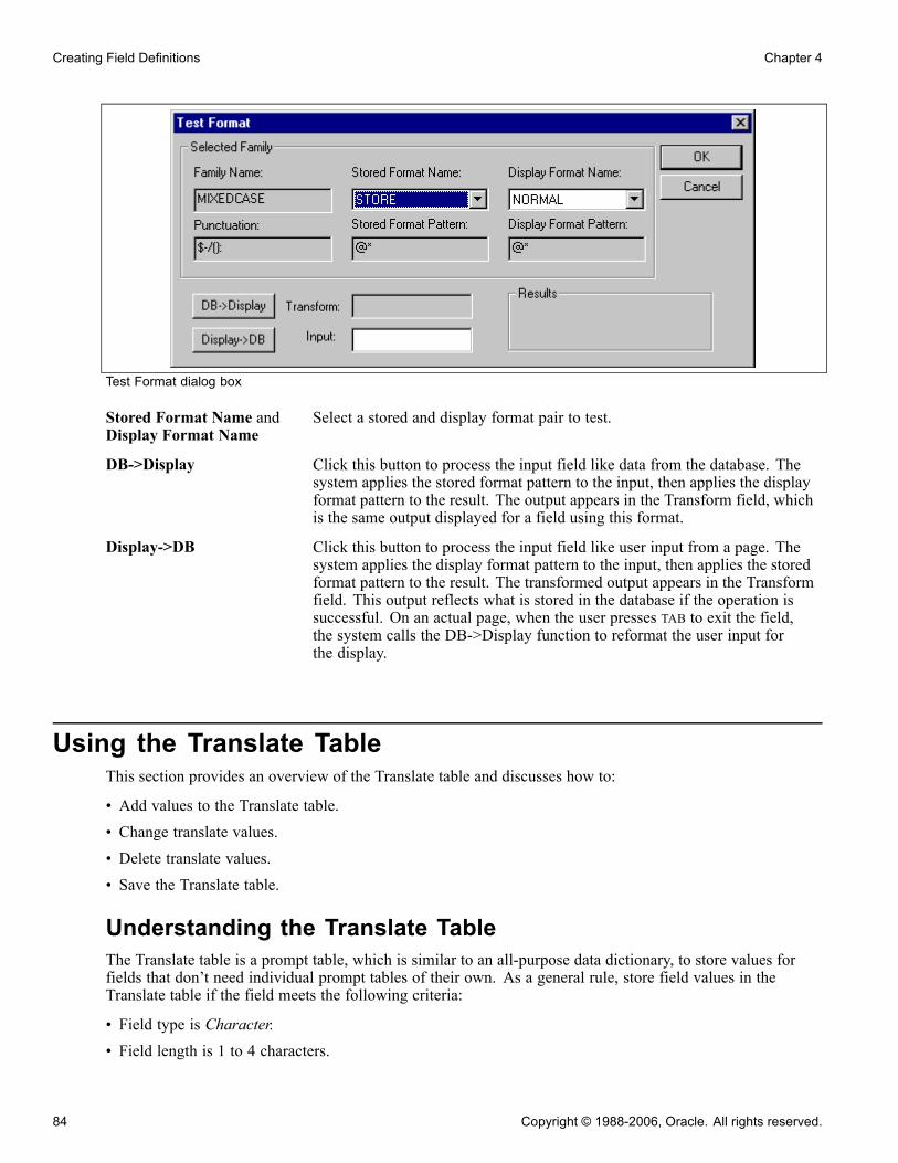
Creating Field Definitions Chapter 4
Test Format dialog box
Stored Format Name andDisplay Format Name
Select a stored and display format pair to test.
DB->Display Click this button to process the input field like data from the database. Thesystem applies the stored format pattern to the input, then applies the displayformat pattern to the result. The output appears in the Transform field, whichis the same output displayed for a field using this format.
Display->DB Click this button to process the input field like user input from a page. Thesystem applies the display format pattern to the input, then applies the storedformat pattern to the result. The transformed output appears in the Transformfield. This output reflects what is stored in the database if the operation issuccessful. On an actual page, when the user presses TAB to exit the field,the system calls the DB->Display function to reformat the user input forthe display.
Using the Translate TableThis section provides an overview of the Translate table and discusses how to:
• Add values to the Translate table.• Change translate values.• Delete translate values.• Save the Translate table.
Understanding the Translate TableThe Translate table is a prompt table, which is similar to an all-purpose data dictionary, to store values forfields that don’t need individual prompt tables of their own. As a general rule, store field values in theTranslate table if the field meets the following criteria:
• Field type is Character.• Field length is 1 to 4 characters.
84 Copyright © 1988-2006, Oracle. All rights reserved.

Chapter 4 Creating Field Definitions
• Field values consist of a relatively small, static set of values that are not maintained by the user.• No other fields relate to this field.
Note. If the only values for a field are Y (yes) and N (no), you don’t need to enter them in the Translate table.The Translate table comes with a field for Y and N named PSYESNO. When you select the Yes/No Table Edit,the system automatically points to the PSYESNO field in the Translate table.
Example of When to Use the Translate TableConsider the relative attributes of a department ID field and a gender field in a company database. In thefollowing table, Department ID is not a good case for using the Translate table, because it requires its ownprompt table. However, the Gender field is a good case for using the Translate Table:
Characteristic Department ID Gender
Field type. Character. Character.
Field length. Longer than 3 characters. 1 character.
Field values. Could be many values, 20 or more. Two possible values.
Other related fields. Related to other fields, likedepartment manager.
Not related to other fields.
Requires maintenance. Yes, users might have to adddepartments.
No, gender is a static value.
Translate Table AttributesThe system maintains the structure of the Translate table and you supply the data. This table contains thefollowing fields:
Field Name Description
FIELDNAME Field name, such as ABSENCE_TYPE.
LANGUAGE_CD Language code.
FIELDVALUE Value for the field.
EFFDT Effective date.
VERSION Internal version number (system-maintained).
EFF_STATUS Status—active or inactive.
Copyright © 1988-2006, Oracle. All rights reserved. 85

Creating Field Definitions Chapter 4
Field Name Description
XLATLONGNAME Thirty-character description; used as a label on pages andreports.
XLATSHORTNAME Ten-character description; used as a label on pages andreports.
LASTUPDDTTM DateTime field showing the last time that a field wasupdated.
LASTUPDOPRID User ID of the user who most recently updated the field.
If you must define more information about a field other than the preceding attributes, create a separate prompttable for the field instead of adding it to the Translate table.
When the user presses the prompt button to prompt for valid values in a field on a page, the system displaysa list of the translate values for a field.
Each value in the Translate table has an effective date, and the date must be earlier than the effective dates ofany rows that reference the value. The translate values delivered by PeopleSoft all have an effective date ofJanuary 1, 1900. Remember this if you add new translate values for a field.
86 Copyright © 1988-2006, Oracle. All rights reserved.
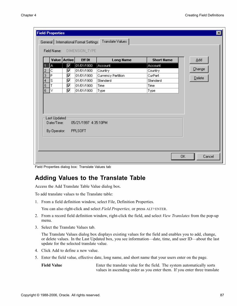
Chapter 4 Creating Field Definitions
Field Properties dialog box: Translate Values tab
Adding Values to the Translate TableAccess the Add Translate Table Value dialog box.
To add translate values to the Translate table:
1. From a field definition window, select File, Definition Properties.You can also right-click and select Field Properties, or press ALT+ENTER.
2. From a record field definition window, right-click the field, and select View Translates from the pop-upmenu.
3. Select the Translate Values tab.The Translate Values dialog box displays existing values for the field and enables you to add, change,or delete values. In the Last Updated box, you see information—date, time, and user ID—about the lastupdate for the selected translate value.
4. Click Add to define a new value.5. Enter the field value, effective date, long name, and short name that your users enter on the page.
Field Value Enter the translate value for the field. The system automatically sortsvalues in ascending order as you enter them. If you enter three translate
Copyright © 1988-2006, Oracle. All rights reserved. 87
Creating Field Definitions Chapter 4
values with field values A, T, and C, they appear in the Translate Valuesdialog box as A, C, T.
Effective Date Enter the date on which you want this value to take effect. The defaultvalue is today’s date. If you want the effective date to predate all rows onyour database, enter 01011900 (January 1, 1900).
Note. The Add button only allows you to add a new, distinct translatevalue. To add a different effective date for the same translate value, selectthe translate value and use the Change button. As long as the effective dateis changed, the system saves the modified entry.
Inactive When a value for a field becomes obsolete, PeopleSoft recommendsthat you select the Inactive check box rather than deleting the value.Deactivating a value enables fields in the database that still contain thevalue to use the correct long and short names. If you delete an obsoletecode from the Translate table and you still have records in the database thatcontain that value, you must change all of those values to active values.
Long Name Enter up to 30 characters.
Short Name Enter up to 10 characters. If you leave this field blank, the systemautomatically copies the first 10 characters of the long name into this field.PeopleSoft recommends that you use mixed case to improve readability.
Changing Translate ValuesSometimes the meaning of a translate value changes, but you still need to retain both values in the Translatetable. For example, suppose that your PROFICIENCY field has a value of E (extremely high). You’vebeen in production for five years, when upper management decides to change the meaning of the valueto Exceptional, as of January 1, 1998.
You can accommodate this type of change by creating a second active entry for the same translate value. Thefirst value is valid in the time range between the effective dates of January 1, 1990 and December 31, 1997.The second entry is valid from January 1, 1998 onward. You don’t want to delete the old entry because thedatabase might contain rows that predate January 1, 1997 and contain this value. You might also maintain theold definition for historical reporting.
To change an existing translate value, select the value and click Change, or double-click the value. The systemdisplays the Change Translate Table dialog box, in which you can make the necessary changes.
Deleting Translate ValuesUse caution when deleting a translate value, unless you are removing an invalid value that was entered bymistake. To deactivate a value because it is no longer used or its meaning has changed, either change thelong and short names, or change the status to Inactive. To delete the value, select it and click the Deletebutton. The row disappears.
Saving the Translate TableAfter you have made all of your changes to the Translate table, you must save the entire field definition. Thereis no save option specifically for translate values. Click OK from the Field Properties dialog box, and thensave the field definition by clicking the Save button or selecting File, Save.
88 Copyright © 1988-2006, Oracle. All rights reserved.

Chapter 4 Creating Field Definitions
To save the Translate table, you must be authorized to modify field definitions. There is a special TranslatesOnly security access level for fields that allows translate values to be updated, but not other field attributes.
Copyright © 1988-2006, Oracle. All rights reserved. 89

Creating Field Definitions Chapter 4
90 Copyright © 1988-2006, Oracle. All rights reserved.
CHAPTER 5
Planning Records, Control Tables, and TableSets
The first step in the application development process is planning. You must consider as a system designer how to store,retrieve, manipulate, and process data that is stored in the tables in your application database.
This chapter provides an overview of the planning process and discusses how to share tables.
Understanding the Planning ProcessThis section discusses:
• Table-based systems.• Normalized relational databases.• Record definition planning.• Effective dates.• Control tables.• TableSets.
Table-Based SystemsPeopleTools-based applications are table-based systems. A database for a PeopleTools application containsthree major sets of tables:
• System Catalog tables store physical attributes of tables and views, which your database managementsystem uses to optimize performance.
• PeopleTools tables contain information that you define using PeopleTools.• Application Data tables house the actual data that your users enter and access through PeopleSoft applicationpages.
This figure shows PeopleSoft database tables and sample names:
Copyright © 1988-2006, Oracle. All rights reserved. 91

Planning Records, Control Tables, and TableSets Chapter 5
SystemCatalog Tables
ApplicationData Tables
PeopleToolsTables
SYSCOLUMNS SYSTABLES
PSRECDEFN PSPNLDEFN PSMENUDEFN
PS_VNDRID PS_EMERGENCY PS_JOB
Tables in a PeopleSoft database
Like a spreadsheet, each of these tables contain columns and rows. Columns define the structure of how thedata is stored. Rows represent the actual data that is stored in the database.
Every time that you create a new definition using PeopleTools, the system inserts rows of data into variousPeopleTools tables. The entries in these tables determine the online processing of the system and what happensduring imports. PeopleSoft maintains the structure of these tables. You maintain data in the PeopleTools tablesrelated to definitions that you create or adapt using PeopleTools. The PeopleTools tables can be viewed in thePPLTOOLS project using the PeopleSoft Application Designer.
To create the application data tables that store the rows of data that your users manipulate:
1. Create a record definition.In doing so you determine the structure of the table, the characteristics of the fields, and any onlineprocessing that you want to occur behind the scenes when a user enters data.
2. Apply the SQL Create option to build the SQL table in which your application data will reside based on asubset of parameters in your record definition.During this process, the system automatically gives the application data table the same name as yourrecord definition, prefaced with PS_.
Normalized Relational DatabasesTo better understand the structure of your PeopleSoft system, you should be familiar with the concept ofa normalized relational database. A normalized table adheres to standards that are designed to improvethe productivity of the database user. Normalization makes the database more flexible, allowing data tobe combined in many different ways.
The standards for a normalized database are called forms, such as first normal form, second normal form,and so on.
92 Copyright © 1988-2006, Oracle. All rights reserved.
Chapter 5 Planning Records, Control Tables, and TableSets
First Normal FormThe first normal form requires that a table contain no repeating groups of nonkey fields. In other words, whenyou’re setting up a record definition, if you encounter a field that could have multiple occurrences, put thatfield in a separate record that is subordinate to the primary record definition (a child record). This allowsunlimited occurrences of a repeating field rather than a specified number. Each row of data is uniquelyidentified by a primary key, which can be a single field or a group of fields that, when concatenated together,form a unique key.
For example, look at the record definition structure of the tables that we use to schedule exam times fordifferent locations in our training database. Here are the necessary fields, in order of importance:
• LOCATION• EXAM_DT• EXAM_TIME
You know that you have multiple exam dates and times per location. You could set up record definitions toaccommodate this data as follows:
Record Definition Fields Key?
LOCATION LOCATION Yes
EXAM LOCATION
EXAM_DT
Yes
Yes
EXAM_TIME LOCATION
EXAM_DT
EXAM_TIME
Yes
Yes
Yes
Because multiple exam dates per location might exist, we added exam dates to the second record definition(child record) that is subordinate to the first (parent) record. Similarly, because there can be multiple examtimes per date, exam times are located in a third record definition that is subordinate to the second.
Second Normal FormThe second normal form dictates that every nonkey field in a table must be completely dependent on theprimary key. If two fields make up the key to a table, every nonkey field must be dependent on both keystogether. For example, if a table has the Employee ID and the Department ID fields as keys, you wouldn’t putthe Department Name field in the table because this field is dependent only on the Department ID field andnot on the Employee ID field.
Third Normal FormThe third normal form is a corollary to the second; it requires that a nonkey field not be dependent on anothernonkey field. For example, if a table is keyed by the Employee ID field, and Department ID is a nonkey fieldin the table, you wouldn’t put the Department Name field in the record because this field is dependent on anonkey field (Department ID). This is why the Department Name field would be found only on the table that iskeyed by the Department ID field, not on any other that contains Department ID.
Copyright © 1988-2006, Oracle. All rights reserved. 93

Planning Records, Control Tables, and TableSets Chapter 5
With the third normal form, you store shared fields in tables of their own and reference them elsewhere. Forexample, you wouldn’t put the Department Name field in every record definition in which the DepartmentID field appears. Instead, you would create a prompt table of department IDs and department names.Similarly, you would create a prompt table of job codes and job titles instead of putting a job title in everyemployee’s record.
Note. When designing record definitions, adherence to the third normal form is recommended to increaseflexibility and reduce data redundancy.
Record Definition PlanningBefore you begin to create record definitions, you should have a clear picture of how you plan to use therecord definition, the fields that it will contain, special edits that you would like to see performed on therecord definition, or specific fields in the definition.
You actually define two layers of information:
• Record level• Field level
At the record level, determine the ultimate purpose of the record definition and how it will be used in thesystem. Is it destined to define an underlying SQL table to hold data? Are you building a view to join or retrieveinformation from other tables? Do you need a temporary work record where you can store derived data?
You can audit record-level changes, as opposed to individual fields contained in the record definition—anefficient alternative if you plan to audit several fields. More sophisticated use of record definitions, such assharing information in TableSets and multilanguage controls, are also established at the record level.
At the field level, plan the details of what types of fields to add. Should they be character fields or numberfields? Should automatic formatting be used? What are the keys to the data stored in the database? Whichfields should you audit? Do you want to specify prompt tables so that users can select from lists of validvalues that are stored elsewhere in the database?
In most cases, if you are creating a record definition for a SQL table, you don’t have to worry aboutrecord-level definitions for parameters and conditions. Unless you change how a record definition is used, thesystem automatically assumes that you are defining a record definition for an underlying SQL table.
Effective DatesEffective dates enable you to keep historical, current, and future information in tables. You can use theinformation to review the past and plan for the future. There are three types of effective dates:
Future Data rows that have effective dates that are after the system date, which isusually today’s date.
Current Data row with the most recent effective date that is closest to today’s (system)date, but not a future date. Only one row is the current row.
History Data rows that have effective dates before the current data row.
The EFFDT (effective date) field has special properties related to the processing of effective dates on rowsand should be used only when needed.
94 Copyright © 1988-2006, Oracle. All rights reserved.

Chapter 5 Planning Records, Control Tables, and TableSets
Unlike regular date fields, which you can use anywhere in the system, use the EFFDT field only on recorddefinitions for which you want to maintain data history—future, current, and past—to store rows of data insequence. This enables you to store multiple occurrences of data based on when it goes into effect.
For effective-dated rows, you can have multiple occurrences of future and history, but only one currentrow of data.
EFFDT is almost always a key and almost never a list item. Activate the Descending Key attribute so thatthe row with the most recent effective date appears first on pages. You might enter %DATE (current systemdate) as the default constant for this field.
Note. Alternatively, you can use %CLIENTDATE as the default constant for the date field. %CLIENTDATEadjusts the date as appropriate to the time zone of the browser.
To enable you to track an accurate history of your effective-dated information, the system invokes special logicwhen you access a record definition that contains EFFDT. The action that you select dictates whether youcan access the row type and what you can do with each type of row:
Action Type View Change Insert New Rows
Update/Display Current, Future Future only Effective Date GreaterThan the Current Row
Update/Display All History, Current, Future Future only Effective Date GreaterThan the Current Row
Correction History, Current, Future All Existing Rows Add New Rows withNo Effective DateRestrictions
Note. For records that do not contain EFFDT, all actions (Update/Display, Update/Display All, and Correction)operate the same way—they retrieve all existing rows for the specified keys.
When you’re running a page with effective-dated records and you insert a row, the system copies the contentsof the prior row into the new row to save you keying time. On a large effective-dated table, you don’t want toreenter all of the data when only a single field changes. Also, anytime you insert an effective-dated row usingPeopleCode, the same copying of the prior row’s contents takes place.
Effective Status In prompt tables, EFF_STATUS (Effective Date Status) usually accompaniesEFFDT. When used with EFFDT, it’s part of the mechanism that enables thesystem to select the appropriate effective-dated rows.You can also use EFF_STATUS by itself as a simple status field, but don’tchange the translate values. They must be A (active) and I (inactive) forEFFDT to work properly. If you need a status field with different values, useor define a different field.
Effective Sequence The EFFSEQ (Effective Sequence) field serves different purposes, dependingon whether it’s paired with EFFDT. If EFFSEQ isn’t paired with EFFDT,EFFSEQ has no special function and can be used as a simple sequencingfield wherever you need one.
Copyright © 1988-2006, Oracle. All rights reserved. 95
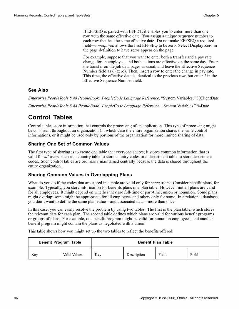
Planning Records, Control Tables, and TableSets Chapter 5
If EFFSEQ is paired with EFFDT, it enables you to enter more than onerow with the same effective date. You assign a unique sequence number toeach row that has the same effective date. Do not make EFFSEQ a requiredfield—unrequired allows the first EFFSEQ to be zero. Select Display Zero inthe page definition to have zeros appear on the page.For example, suppose that you want to enter both a transfer and a pay ratechange for an employee, and both actions are effective on the same day. Enterthe transfer on the job data pages as usual, and leave the Effective SequenceNumber field as 0 (zero). Then, insert a row to enter the change in pay rate.This time, the effective date is identical to the previous row, but enter 1 in theEffective Sequence Number field.
See AlsoEnterprise PeopleTools 8.48 PeopleBook: PeopleCode Language Reference, “System Variables,” %ClientDate
Enterprise PeopleTools 8.48 PeopleBook: PeopleCode Language Reference, “System Variables,” %Date
Control TablesControl tables store information that controls the processing of an application. This type of processing mightbe consistent throughout an organization (in which case the entire organization shares the same controlinformation), or it might be used only by portions of the organization for more limited sharing of data.
Sharing One Set of Common ValuesThe first type of sharing is to create one table that everyone shares; it stores common information that isvalid for all users, such as a country table to store country codes or a department table to store departmentcodes. Such control tables are ordinarily maintained centrally because the data is shared throughout theentire organization.
Sharing Common Values in Overlapping PlansWhat do you do if the codes that are stored in a table are valid only for some users? Consider benefit plans, forexample. Typically, you store information for benefits plans in a plan table. However, not all plans are validfor all employees. It might depend on whether they are full-time or part-time, union or nonunion. Some plansmight overlap; some might be appropriate for all employees and others only for some. In a relational database,you don’t want to define the same plan value—and associated data—more than once.
In this case, you can easily resolve the problem by using two tables. The first is the plan table, which storesthe relevant data for each plan. The second table defines which plans are valid for various benefit programsor groups of plans. For example, one benefit program might be valid for nonunion employees, and anotherbenefit program might contain the plans as negotiated with a union.
This table shows how you might set up the two tables to reflect the benefits offered:
Benefit Program Table Benefit Plan Table
Key Valid Values Key Description Field Field
96 Copyright © 1988-2006, Oracle. All rights reserved.
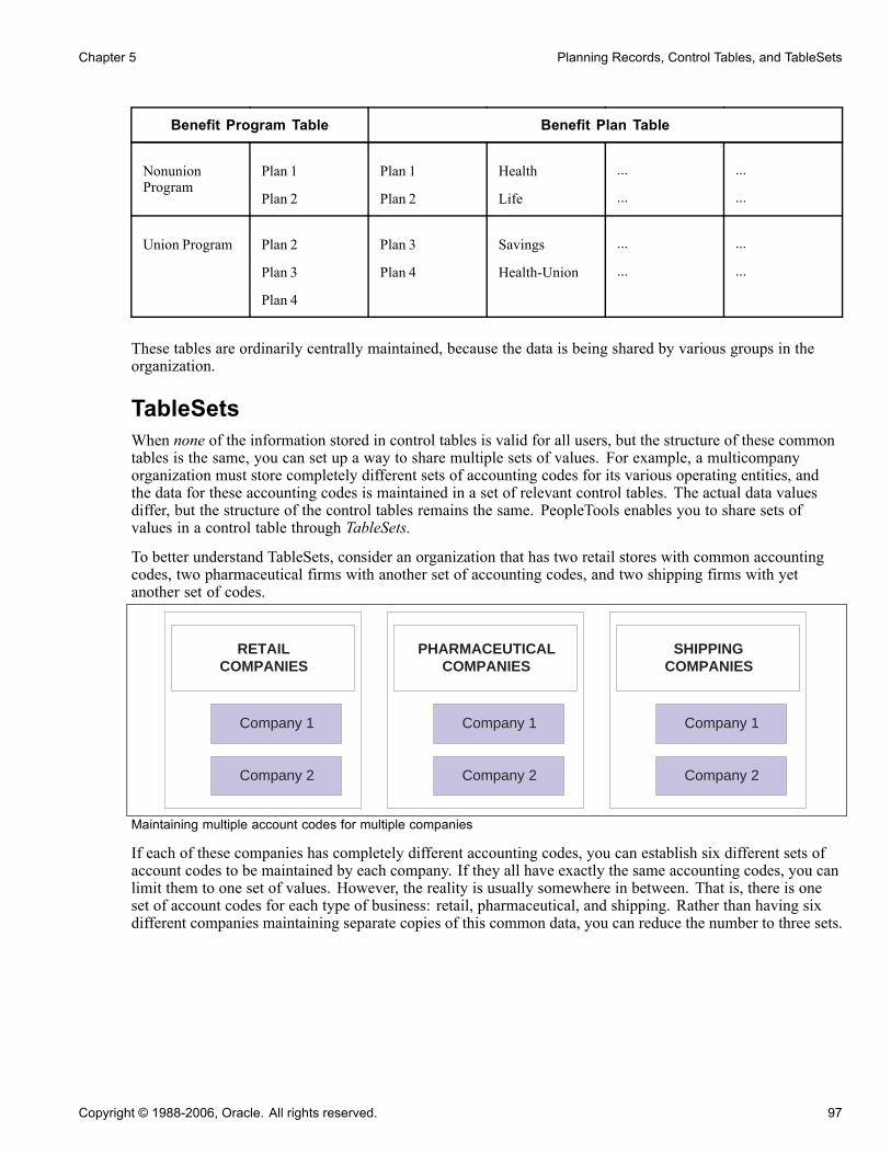
Chapter 5 Planning Records, Control Tables, and TableSets
Benefit Program Table Benefit Plan Table
NonunionProgram
Plan 1
Plan 2
Plan 1
Plan 2
Health
Life
...
...
...
...
Union Program Plan 2
Plan 3
Plan 4
Plan 3
Plan 4
Savings
Health-Union
...
...
...
...
These tables are ordinarily centrally maintained, because the data is being shared by various groups in theorganization.
TableSetsWhen none of the information stored in control tables is valid for all users, but the structure of these commontables is the same, you can set up a way to share multiple sets of values. For example, a multicompanyorganization must store completely different sets of accounting codes for its various operating entities, andthe data for these accounting codes is maintained in a set of relevant control tables. The actual data valuesdiffer, but the structure of the control tables remains the same. PeopleTools enables you to share sets ofvalues in a control table through TableSets.
To better understand TableSets, consider an organization that has two retail stores with common accountingcodes, two pharmaceutical firms with another set of accounting codes, and two shipping firms with yetanother set of codes.
RETAILCOMPANIES
SHIPPINGCOMPANIES
PHARMACEUTICALCOMPANIES
Company 1
Company 2
Company 1
Company 2
Company 1
Company 2
Maintaining multiple account codes for multiple companies
If each of these companies has completely different accounting codes, you can establish six different sets ofaccount codes to be maintained by each company. If they all have exactly the same accounting codes, you canlimit them to one set of values. However, the reality is usually somewhere in between. That is, there is oneset of account codes for each type of business: retail, pharmaceutical, and shipping. Rather than having sixdifferent companies maintaining separate copies of this common data, you can reduce the number to three sets.
Copyright © 1988-2006, Oracle. All rights reserved. 97

Planning Records, Control Tables, and TableSets Chapter 5
RETAILCOMPANIES
SHIPPINGCOMPANIES
PHARMACEUTICALCOMPANIES
Company 1
Company 2
Company 1
Company 2
Company 1
Company 2
RETAILAccount Codes
PHARMACEUTICALAccount Codes
SHIPPINGAccount Codes
Sharing multiple account codes among companies
You can also handle exceptions. Suppose that Retail Company 2, a recently acquired company, has its ownunique set of account codes. A separate set of values should be maintained for this company as an exceptionto the retail rule.
RETAILCOMPANIES
SHIPPINGCOMPANIES
PHARMACEUTICALCOMPANIES
Company 1
Company 2
Company 1
Company 2
Company 1
Company 2
RETAILAccount Codes
PHARMACEUTICALAccount Codes
SHIPPINGAccount Codes
RETAIL Company2Account Codes
ACCOUNT CODES
Six Sets ofPossible AccountCodes
Three Sets ofStandard ValuesOne Set ofUnique Values
Three StandardSets Plus OneException forRetail Company 2
Retail TableSet Pharmaceutical TableSet Shipping TableSet Retail Company2
Sharing account codes among companies with exceptions
98 Copyright © 1988-2006, Oracle. All rights reserved.
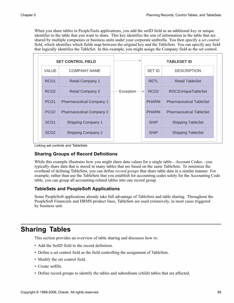
Chapter 5 Planning Records, Control Tables, and TableSets
When you share tables in PeopleTools applications, you add the setID field as an additional key or uniqueidentifier to the table that you want to share. This key identifies the sets of information in the table that areshared by multiple companies or business units under your corporate umbrella. You then specify a set controlfield, which identifies which fields map between the original key and the TableSets. You can specify any fieldthat logically identifies the TableSet. In this example, you might assign the Company field as the set control.
SET CONTROL FIELD
VALUE COMPANY NAME
Retail Company 1RCO1
Retail Company 2RCO2
Pharmaceutical Company 1PCO1
Pharmaceutical Company 2PCO2
Shipping Company 1SCO1
Shipping Company 2SCO2
TABLESET ID
SET ID DESCRIPTION
Retail TableSetRETL
ROC2UniqueTableSetRCO2
Pharmaceutical TableSetPHARM
Pharmaceutical TableSetPHARM
Shipping TableSetSHIP
Shipping TableSetSHIP
Exception
Linking set controls and TableSets
Sharing Groups of Record DefinitionsWhile this example illustrates how you might share data values for a single table—Account Codes—youtypically share data that is stored in many tables that are based on the same TableSets. To minimize theoverhead of defining TableSets, you can define record groups that share table data in a similar manner. Forexample, rather than use the TableSets that you establish for accounting codes solely for the Accounting Codetable, you can group all accounting-related tables into one record group.
TableSets and PeopleSoft ApplicationsSome PeopleSoft applications already take full advantage of TableSets and table sharing. Throughout thePeopleSoft Financials and HRMS product lines, TableSets are used extensively, in most cases triggeredby business unit.
Sharing TablesThis section provides an overview of table sharing and discusses how to:
• Add the SetID field to the record definition.• Define a set control field as the field controlling the assignment of TableSets.• Modify the set control field.• Create setIDs.• Define record groups to identify the tables and subordinate (child) tables that are affected.
Copyright © 1988-2006, Oracle. All rights reserved. 99

Planning Records, Control Tables, and TableSets Chapter 5
• Define TableSet controls.• Share trees.
Understanding Table SharingTo share tables, you must modify the record definitions for both the table that you want to share and theone that contains the set control field. Using the online PeopleTools Utilities for TableSets, you define theterms or controls for sharing.
For example, in the PeopleTools database, there are three companies: one U.S.-based parent company (PST)and two sister companies (CCB in the U.S. and VNB in Canada). In this organization, all of the U.S.-basedcompanies share one set of accounting codes, and all of the Canadian-based VNB companies share another.
U.S. Account Codes Canadian Account Codes Description
123456789 123456789 Teller
987654321 987600000 Customer Service
CCB-4476-EXTSAL-USA VNB-4476-EXTSAL-CDN Extraordinary Salary Employees
CCB-4476-REGSAL-USA VNB-4476-REGSAL-CDN Regular Salary Employees
These two groups of companies must maintain parallel sets of accounting codes, and in some cases, they usethe same code, uniquely identified for U.S. or Canadian companies.
We must set up the Account Code table so that users who access that page or prompt for valid values see onlythe values for their respective companies, depending on whether they’re located in the U.S. or Canada.
To do this:
1. Modify the Account Code table, which will be shared, and the Company table, the values of which (CCB,PST, VNB) control the TableSets that are used.
2. Create two TableSet IDs:• USA: For U.S. companies.• CAN: For Canadian companies.
100 Copyright © 1988-2006, Oracle. All rights reserved.

Chapter 5 Planning Records, Control Tables, and TableSets
US BASEDCOMPANIES
ACCOUNT CODES
CANADIANCOMPANIES
PST
CCB
WNB
WNB - Quebec
USA TableSet
CAN TableSet
USAAccount Codes
CANADIANAccount Codes
TableSets and set control fields
Assigning Set Control FieldsIf you plan to use the Table Sharing feature to add an additional high-level key to identify common sets ofvalues and handle exception values, you enter a set control field. The set control field determines which set ofvalues appears, based on how you define table sharing.
Table sharing is usually applied in multicompany environments, in which you might want to share certaintables in some operating entities while allowing others to retain control over the contents of their own. Usethe feature to maintain a single table in which you can store multiple sets of values to be used by differententities in your organization.
When you create a record definition that will be shared, you add the field setID as a high-level key. The setIDvalue is controlled by the key that you select in the Set Control Field drop-down list box in the RecordProperties dialog box. These setIDs identify groups of tables to be shared and enable each business entityto identify whether it wants to use the corporatewide table or maintain its own. Enter the name of the keyas your set control field for each record definition that will be shared.
Copyright © 1988-2006, Oracle. All rights reserved. 101

Planning Records, Control Tables, and TableSets Chapter 5
For example, if you have several companies in your organization, many of which share the same set ofaccount codes, add a SetID field to the Account table record definition. In this definition, enter Company.as the set control field. This enables different companies to access the account values stored in the sameAccount table. As each company defines its set controls, it has the option to use the shared Account tableor maintain control of its own.
Adding the SetID Field to Record DefinitionsAdd the setID field to the record definition for table sharing purposes.
Adding setIDs to record definitions
To add the setID:
1. Open the record definition for the table that you want to share.2. Select New, Field, Character.3. Enter the special field that PeopleTools provides for table sharing:SETIDSetID is a 5-character field. Add it to the top of your record definition list, and define it as a required key,search and list item, with a prompt table edit against the PeopleTools SETID_TBL.
Defining Set Control FieldsAfter you add the setID field to your record, identify the set control field in Record Properties.
To define the set control field:
1. Select Edit, Definition Properties from the menu.2. Select the Use tab.3. Select the field that identifies the appropriate setID in the Set Control Field drop-down box.
See Chapter 5, “Planning Records, Control Tables, and TableSets,” Understanding Table Sharing, page 100.4. Click OK to save your changes.5. Use the SQLAlter process to alter your underlying SQL table.6. When the system prompts you for a default setID, enter the most common setID for your company.
102 Copyright © 1988-2006, Oracle. All rights reserved.

Chapter 5 Planning Records, Control Tables, and TableSets
Modifying the Set Control FieldIf you are sharing tables or using a set control field that is not already defined as such in your PeopleSoftapplication, you must make some modifications to the record definition for the table in which you store valuesfor your specified set control field. For example, all PST company codes are stored in the COMPANY_TBL.
Here, you must add PeopleCode to the set control field so that each time you add a new value, the systempopulates the set controls in PeopleTools utilities, where you assign the appropriate TableSets.
Attaching PeopleCode to your set control field
This program assigns a default setID with the same value as the Set Control Field value, for each newCOMPANY row that you add to the COMPANY_TBL. For example, when you add a row for CCB in theCompany table, it creates a default setID of CCB. This way, each value that you add is assigned a uniqueTableSet until you assign shared TableSets in the Utilities window.
You can easily clone and modify this program to change the ADD_SETID and ADD_TABLESET_CNTRLstatements to reflect your table sharing objectives. Alternatively, if you’re working with existing TableSetfunctionality, you can point to a model setID that is delivered with your PeopleSoft application.
See AlsoChapter 7, “Administering Data,” Altering Tables, page 161
Creating SetIDsAfter you prepare for sharing your table, you define the setIDs that logically group information. When youdefine setIDs, you create groups that might naturally share more than one table. For example, although CCBand VNB are planning to share only the ACCT_CD_TBL now, the setIDs that you set up might define logicaldivisions in the organization that serve as the basis for sharing all accounting-related tables. Describe your setsto give them as broad an application as is practical in your organization.
If possible, use descriptions that denote the shared table and set control field. For example, for CCB and VNB,we added two TableSet IDs, identifying them as related to accounting codes for companies.
Copyright © 1988-2006, Oracle. All rights reserved. 103
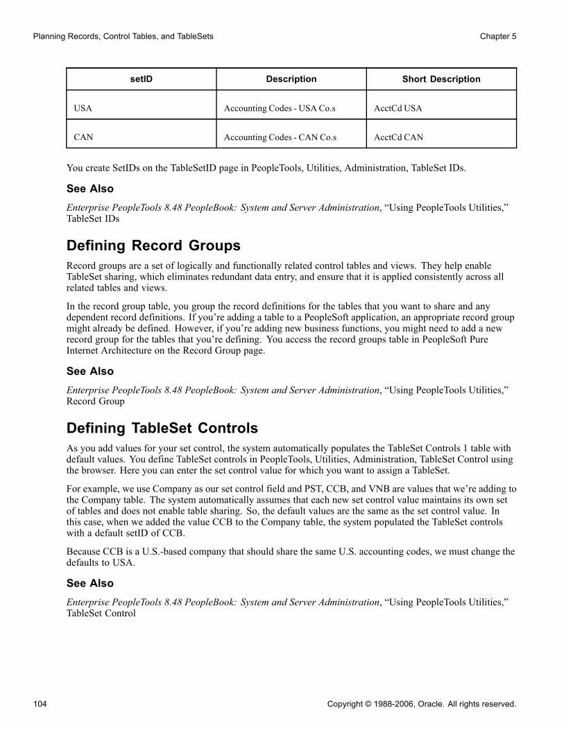
Planning Records, Control Tables, and TableSets Chapter 5
setID Description Short Description
USA Accounting Codes - USA Co.s AcctCd USA
CAN Accounting Codes - CAN Co.s AcctCd CAN
You create SetIDs on the TableSetID page in PeopleTools, Utilities, Administration, TableSet IDs.
See AlsoEnterprise PeopleTools 8.48 PeopleBook: System and Server Administration, “Using PeopleTools Utilities,”TableSet IDs
Defining Record GroupsRecord groups are a set of logically and functionally related control tables and views. They help enableTableSet sharing, which eliminates redundant data entry, and ensure that it is applied consistently across allrelated tables and views.
In the record group table, you group the record definitions for the tables that you want to share and anydependent record definitions. If you’re adding a table to a PeopleSoft application, an appropriate record groupmight already be defined. However, if you’re adding new business functions, you might need to add a newrecord group for the tables that you’re defining. You access the record groups table in PeopleSoft PureInternet Architecture on the Record Group page.
See AlsoEnterprise PeopleTools 8.48 PeopleBook: System and Server Administration, “Using PeopleTools Utilities,”Record Group
Defining TableSet ControlsAs you add values for your set control, the system automatically populates the TableSet Controls 1 table withdefault values. You define TableSet controls in PeopleTools, Utilities, Administration, TableSet Control usingthe browser. Here you can enter the set control value for which you want to assign a TableSet.
For example, we use Company as our set control field and PST, CCB, and VNB are values that we’re adding tothe Company table. The system automatically assumes that each new set control value maintains its own setof tables and does not enable table sharing. So, the default values are the same as the set control value. Inthis case, when we added the value CCB to the Company table, the system populated the TableSet controlswith a default setID of CCB.
Because CCB is a U.S.-based company that should share the same U.S. accounting codes, we must change thedefaults to USA.
See AlsoEnterprise PeopleTools 8.48 PeopleBook: System and Server Administration, “Using PeopleTools Utilities,”TableSet Control
104 Copyright © 1988-2006, Oracle. All rights reserved.

Chapter 5 Planning Records, Control Tables, and TableSets
Sharing TreesTo share trees as well as tables and views, complete TableSet Controls 2 in the same way that you did TableSetControls 1. For example, if PST and CCB want to share one department tree for organizational security andVNB another, you assign the appropriate setID for each value.
Defining TableSet Controls for TreesTo define TableSet controls for trees:
1. Select PeopleTools, Utilities, Administration, TableSet Control in PeopleSoft Pure Internet Architecture.
2. Enter the name of the set control value for which you want to assign a TableSet in the search page.
For example, we use Company as our set control field and PST, CCB, and VNB are values that we’readding to the Company table.
Because you already assigned a default setID in TableSet Controls 1, the system displays the defaultsetID that you assigned to this field value. If you create another TableSet for sharing trees, you canchange this value.
3. Specify the tree name.
Click the prompt button next to the Tree Name field for a list of only the tree definitions with the same setcontrol field (which has PostSave PeopleCode that recognizes it as a TableSet control field).
This prompt list comes from a SQL view of tree definitions with that set control field that haven’t alreadybeen associated with a tree group.
4. In each tree row, specify the appropriate setID.
5. Save your changes.
Viewing All Record Definitions Associated With a Set ControlYou can view all record definitions that are associated with a set control in the Record Group tab of theTableSet Controls page.
Example of Set ControlsAfter you set up and define all of your set controls, you can see the results by looking at pages on which youreference codes that are stored in a shared table. For example, on Administer Workforce, Use, Job Data 1 and 2pages, Account Code is an optional field that is edited against the ACCT_CODE_TBL. In this component, thesystem identifies the company based on the department to which an employee is assigned. For example, SimonSchumacher is in department 10100, which is associated with the company CCB.
Select the Job Data 2 tab and enter 8001 or Simon Schumacher in the search record dialog box to retrieve aCCB row, for which the company is defined in the department table. Here, you can see that Simon worksin department 00001, which identifies him as a CCB employee. If you click the prompt button next to theAccount Code field, the system displays only those rows in the Account Code Table that are associatedwith USA, the setID for CCB.
Alternatively, if you access the job row for Joan Avery, an employee of VNB, and click the prompt buttonfor the same Job Data 2 Account Code field, you retrieve only values that are associated with CAN, thesetID for VNB.
Copyright © 1988-2006, Oracle. All rights reserved. 105

Planning Records, Control Tables, and TableSets Chapter 5
106 Copyright © 1988-2006, Oracle. All rights reserved.

CHAPTER 6
Creating Record Definitions
Fields that are grouped together as a unit are record definitions. A record definition represents what the underlyingStructured Query Language (SQL) database tables look like and how they process data.
This chapter discusses how to:
• View record definitions.• Save record definitions.• Name record definitions.• Create a new record.• Open an existing record.• Manipulate fields in record definitions.• Set record properties.• Set record field properties.
Viewing Record DefinitionsYou can see four views of the record by selecting View from the main toolbar: Field Display, Use Display,Edits Display, and PeopleCode Display.
This section lists common elements and discusses how to:
• View basic field definitions.• View key-related characteristics and default values.• View editing options.• View PeopleCode program types.• Reorder fields.• Size and sort columns.
Common Elements Used in This SectionNum (number) The number of the field in the order in which it is defined in the record.
Field Name The name of the field in the SQL database.
Type The data type of the field, such as character, number, or date.
Copyright © 1988-2006, Oracle. All rights reserved. 107

Creating Record Definitions Chapter 6
Viewing Basic Field DefinitionsField Display mode shows the basic field definition characteristics for fields in the record definition. Fielddefinition characteristics are global—they affect all record definitions in which the field is used. To open theassociated field definition, right-click while in Field View and select View Definition.
Len (length) Indicates the maximum length of the field, including decimal places.
Format Notes special formatting for the field, such as mixed case, date, internationalphone number, or RawBinary.
Short Name and LongName
Displays the short and long names of the field as users see it on pages.
Viewing Key-Related Characteristics and Default ValuesUse Display mode shows key-related characteristics and default values for fields that determine how fields areused in a record. The use characteristics might differ for fields that are used on more than one record definition.Double-click the field to access the Record Field Properties dialog box in which you define these parameters.
Key Indicates whether the field is a key to the record definition. Key fields areincluded in an index that is automatically created during the table build process.
The word "Not" in this column indicates that this field cannot be usedas a chart field. This can only be set through PeopleCode using theSetDBFieldNotUsed function.
See Enterprise PeopleTools 8.48 PeopleBook: PeopleCode LanguageReference, “PeopleCode Built-in Functions,” SetDBFieldNotUsed.
Ordr (order) Indicates the order of key fields in the index. This order can be configuredfrom the Index dialog box and is reflected in this column.
Dir (direction) Indicates the order in which the key field indexes are created in the database:ascending or descending.
CurC (currency control) The currency format for this field is controlled by the currency code inanother field.
Srch (search) Indicates a search key—a field for which one is prompted in a search recorddialog box.
List Indicates a list box item—that is, whether the values for the field appear inthe search record list box.
Sys (system) Indicates that the field is generated and maintained by the system.
Audt (audit) Specifies whether additions, changes, or deletions to data in this field arewritten to the standard PeopleTools Audit Table (PSAUDIT).
Default Represents the default value that is used to initialize the field.
Viewing Editing OptionsEdits Display mode shows all editing options (edit as a validation rule) that are available for fields in a record.Edits on a field vary from one record definition to another. To define parameters, access the Record FieldProperties dialog box by double-clicking the field.
108 Copyright © 1988-2006, Oracle. All rights reserved.

Chapter 6 Creating Record Definitions
Req (required) Indicates whether the field is required. A user must enter a value before therecord can be written to the database.
Edit Specifies that the values for this field are validated against a table.The translate table stores the codes and translate values:Y/N (yes or no): Only two values, Y or N, are valid.Prompt: Values reside in a designated prompt table.
Prompt Table Indicates the prompt table for a field. When a user clicks the prompt buttonor presses the ALT+5 key combination on a page, the values that are storedin this table are retrieved.
Set Control Field If you plan to use the Table Sharing feature to add an additional high-levelkey to identify common sets of values and handle exception values, add thename of the key here. The set control field determines which set of valuesappears, based on how you define table sharing.
Rs Dt (reasonable date) Specifies whether a reasonable date test is performed on a date field. All datefields are automatically edited to ensure that you can enter only valid values.The reasonable date test warns if the date is outside a 30-day range before andafter the current date. You can use this, among other things, to guard againstentering the wrong year in a date.
Event Indicates whether any type of PeopleCode has been added for this field. (Youcan also determine this because the field is bold if PeopleCode has been added.)
Viewing PeopleCode Program TypesPeopleCode Display mode contains a column for each PeopleCode program type. This display indicates whichfields contain PeopleCode events with a check mark in the event type column. Double-click on a cell to launchthe PeopleCode Editor. Note that fields containing PeopleCode are in bold in all display modes.
Copyright © 1988-2006, Oracle. All rights reserved. 109

Creating Record Definitions Chapter 6
PeopleCode Display mode with PeopleCode Editor
Reordering FieldsYou can reorder the display of fields in the record definition by double-clicking the attribute name. Forexample, if you double-click Field Name, the fields appear in alphabetical order; double-clicking Num returnsthe fields to their numeric order. This doesn’t change the order of the fields in the actual record. The numbersthat the fields are originally assigned remain the same. This is important when it comes to key fields.
To actually reorder the fields in the records, you must cut and paste or select the field and move it.
Sizing and Sorting ColumnsYou can change column lengths in any of the displays by dragging them to the appropriate size with yourcursor. For example, you might make the short name column smaller so that the entire long name for each fieldappears. The default sizing of all columns returns after you close the record and reopen it.
You can also sort the rows in columns by double-clicking the column heading. For example, double-clickingthe Num column heading returns the list of record fields to the default sort order.
Saving Record DefinitionsPeopleSoft recommends that you save your work every time that you define a new record definition. As soonas you add or change one element in the new definition, save your work and name the record. You cannot savea record definition until you make at least one change to the record definition by changing record properties,adding or deleting at least one field, or changing the record field properties.
110 Copyright © 1988-2006, Oracle. All rights reserved.

Chapter 6 Creating Record Definitions
You cannot add PeopleCode to a field until you save the record definition.
To save a new record definition, select File, Save or File, Save As. If you haven’t named the definition,the system prompts you to enter a record name. The system also prompts you to set the tablespace withthe Change Space dialog box.
See Chapter 7, “Administering Data,” Setting the Tablespace, page 175.
Naming Record DefinitionsUse these guidelines for record definition names:
• The name length can be up to 15 characters, with the exception of the Temporary Table type, which has amaximum length of 13.
• The name must begin with a letter and can contain underscores to make it more readable.• Avoid special characters, such as # or $, which can cause problems in some database environments.
See Chapter 2, “Using PeopleSoft Application Designer,” Saving Definitions, page 29.
Record Naming ConventionsTo help identify the purpose of different types of record definitions, PeopleSoft recommends that you adoptthese naming conventions for record definition names, and use these suffixes:
_TBL Identifies an edit or prompt table that contains data that is used for validation,as opposed to data that is maintained by the application. Prompt tablesstore commonly used values. They include, but are not limited to, controltables, which store company-wide values. For example, the location table(LOCATION_TBL) stores values for all operating locations in which yourcompany does business; the country table (COUNTRY_TBL) stores values forall valid countries.
_VW Identifies a record definition that is physically implemented by defininga SQL view.
_DVW Identifies a dynamic view.
_WRK Identifies derived work records.
_SBR Identifies subrecords.
_QVW Identifies a query view.
_WL Identifies the record as a worklist record definition.
In some cases, PeopleSoft also uses these prefixes to identify special types of record definitions:
R_ Identifies work record definitions for Structured Query Report reports. Theremainder of the record name consists of the program or report ID.
AUDIT_ Identifies record definitions that store audit information for other recorddefinitions in the database.
Copyright © 1988-2006, Oracle. All rights reserved. 111
Creating Record Definitions Chapter 6
WEBLIB_ Identifies record definitions that store internet scripts. Internet scripts aregenerally located in FieldFormula PeopleCode events. You must grant accessin the Security component for a WEBLIB record with an internet script beforeit can be run in a PeopleCode program.
FUNCLIB_ Identifies record definitions that contain written PeopleCode functions, asopposed to built-in functions. You can include these records in the componentand call them as functions. These self-developed functions are generallylocated in FieldFormula events, and the records are usually derived.
DERIVED_ Identifies shared record definitions (across an application module or group)that have fields for PeopleCode events.
Creating a New RecordThis section discusses how to create new record definitions.
To create a new record definition:
1. Select File, New.2. Select Record.3. Click OK.The object workspace appears so that you can build a list of fields in a record definition.
4. Select the Record Type tab to define the type of record definition.
SQL Table (StructuredQuery Language table)
Select to define a record definition that has a corresponding physical SQLtable in the database. Create this table when you run the Build Operationfrom the Build menu. This is the default setting.
SQL View (Structured QueryLanguage view)
Select to define a record definition that corresponds to a SQL view, whichis not a physical SQL table in the database, but rather fields from one ormore SQL tables that are reorganized into a different sequence. Thisprovides an alternate view of information that is stored in tables.To create the SQL view, click the Click to open SQL Editor button, enter aSQL Select statement, and then run the Build process.
See Chapter 6, “Creating Record Definitions,” Creating SQL View andDynamic View Select Statements, page 133.
Dynamic View Select to define a record definition that can be used like a view in pagesand PeopleCode, but is not actually stored as a SQL view in the database.Instead, the system uses the view text as a base for the SQL Select that isperformed at runtime. Dynamic views can provide superior performance insome situations, such as search records and in PeopleCode Selects, becausethey are optimized more efficiently than normal SQL views.
Note. Keys for dynamic views should not be effective date fields.
112 Copyright © 1988-2006, Oracle. All rights reserved.

Chapter 6 Creating Record Definitions
Derived/Work Select to define the record definition as a temporary workspace to useduring online page processing. A derived or work record is not stored inthe database, so you do not build it.
SubRecord Select to define the record definition as a subrecord—a group of fields thatare commonly used in multiple record definitions—that you can add toother record definitions. This way, you can change a group of fields inone place, as opposed to changing each record definition in which thegroup of fields is used.
Query View Select to define the record definition as a view that is constructed usingthe PeopleSoft Query tool. Before you can create the view, PeopleSoftApplication Designer prompts you to save the definition.
Temporary Table Select to define the record definition as a temporary table. Temporaryimages of the table can be specified on the PeopleTools Options page.Temporary tables are used for running PeopleSoft Application Enginebatch processes. Temporary tables can store specific data to update withoutrisking the main application table.
Non Standard SQLTable Name (nonstandardStructured Query Languagetable name)
Specify the SQL table name that you are defining, to override the standardconvention of prefixing PS_ to the record name.
See AlsoChapter 6, “Creating Record Definitions,” Manipulating Fields in Record Definitions, page 113
Opening an Existing RecordOpen a record definition in the same manner you open other definitions in PeopleSoft Application Designer. Inthe open dialog box you can narrow the search by selecting a record type or project. You can also open anexisting record from the project tree view by double-clicking a record name.
Manipulating Fields in Record DefinitionsThis section provides an overview of fields in record definitions and discusses how to:
• Insert fields into records.
• Insert subrecords into records.
Understanding Fields in Record DefinitionsYou create record definitions by adding field definitions to a new record definition or by cloning and modifyingan existing record definition. You can add fields in any order and reorder them at any time. Keys should belocated at the top of the record definition, in order of importance.
Copyright © 1988-2006, Oracle. All rights reserved. 113
Creating Record Definitions Chapter 6
Each field has basic attributes that are shared across all records that contain the field. These field propertiesinclude data type, field name, long name, short name, field length (or integer and decimal positions),formatting, help context number, and translate values. If you change any of these attributes for a field, thechange affects every occurrence of the field in every record definition. If the change isn’t appropriate for everyoccurrence of this field, consider defining a new field instead.
Note. Changing a field name or length requires modification of the underlying SQL table, either by runningthe SQL Build or SQL Alter menu items or by a system administrator action. For example, if you changea field length on one record definition and 30 other record definitions contain the same field name, youhave 31 records that must be built or altered. If the records are all within one project, you can run the buildprocess on the project instead.
Inserting Fields Into RecordsYou can insert a field into a record in one of several ways:
• Using the project workspace tree.To insert a field into a record definition directly from the project workspace by using drag and drop:1. Locate a field using the PeopleSoft Application Designer project workspace tree.2. Drag the field from the project workspace tree to the object workspace.The field and its attributes are automatically added to the list of fields in the record definition.
• Using the Insert menu (Insert, Field).Use the Insert, Field menu selection to search for fields with selection criteria, and then add them to therecord using the Insert button. You can also double-click a selected field definition and select Insert the FieldDefinition. Fields are inserted below the selected field in the record definition.
• Dragging fields from existing records.To drag a field from one record definition to another:1. Open a record that contains the fields that you need.2. Select the field.3. Drag the field to a new record.
Inserting Subrecords Into RecordsSelect Insert, SubRecord to search, select, and insert subrecords into a record. A subrecord enables you toadd a group of fields that are commonly used in multiple record definitions. A subrecord must be definedbefore it can be inserted into a record definition.
Viewing a SubrecordAny open record in which a subrecord is inserted can have the subrecord expanded into the same recorddefinition window by selecting View, Expand All Subrecords. After selecting this option, the parent recorddefinition expands to show the fields in the subrecord. Subrecord fields are shaded.
When the subrecord is expanded, you cannot insert, cut, delete, paste, reorder, and sort fields. If you reorderedthe display of the fields, you cannot expand the subrecords.
114 Copyright © 1988-2006, Oracle. All rights reserved.

Chapter 6 Creating Record Definitions
The expanded subrecord fields are read-only, which means that you cannot see the properties of thesefields. To access the properties, first open the subrecord. The shortcut to opening a subrecord is to clickthe expanded subrecord and select View Definition. This opens a subrecord definition from which you canview the properties of the fields.
Collapse the subrecord by selecting View, Collapse All Subrecords.
Nesting SubrecordsNested subrecords are fully supported to any level. Expanding a record toggles the record field list to show allof the fields from all levels of nesting. Changes to subrecords are immediately reflected in expanded records.
Editing PeopleCode in SubrecordsYou can edit PeopleCode that is attached to a subrecord field by double-clicking the appropriate field as itappears in the expanded record. Any PeopleCode changes that you make apply to all records that contain thatsubrecord.
Setting Record PropertiesAfter you create a record definition, you’ll want to apply attributes so the record functions. Access the dialogbox by selecting Record Properties, then either the General or Use tab. This section discusses how to:
• Set general properties.• Set use properties.• Create user-defined audit record definitions.
Setting General PropertiesAccess the Record Properties, General tab.
Description Enter a descriptive name for the record.
Record Definition Enter appropriate comments in this area, including details about the recordtype, use, parent and child relationships, or other information that is importantto other application designers.
Owner ID Displays a list of applications with which this record is used. This list ishelpful to identify the applications with which the record is associated duringapplication development.
Last Updated Displays the date and time of the last modification that was made to the recordand the name of the user who made the modification.
Setting Use PropertiesAccess the Record Properties, Use tab.
These properties control the way the record definition is used in the system.
Specify the field with which the system maps between the original key and the tablesets in the Set ControlField drop-down list box.
Copyright © 1988-2006, Oracle. All rights reserved. 115

Creating Record Definitions Chapter 6
See Chapter 5, “Planning Records, Control Tables, and TableSets,” Defining Set Control Fields, page 102.
Record Relationship Settings
Parent Record If this is a subordinate or child record, specify the parent record.
Related Language Record Specify a related language record:
• The master record definition, which contains the appropriate key andnonkey field definitions.
• A clone of the master record definition, to which you add an additional keyfor language code.This is the related language record definition. This definition should containonly those nonkey fields for which contents vary by language. Link the tworecord definitions by specifying the name of the related language recorddefinition in this field on the master record definition.At runtime, the system checks the user’s language preference and retrievesthe data value from the appropriate related language record definition.
Query Security Record Specify a query security record if you want secure access to a record using asecurity view.
Optimization DeleteRecord
Specify a delete record to use for optimization.
Record Name Specify the user-defined audit record.
Audit OptionsWhile you can audit individual fields at the field level, you might find it more efficient to have the system auditthe entire row whenever a user adds, changes, or deletes information. With record-level audits, the systemfocuses on rows of data, instead of specific fields. Consequently, a record-level audit writes a single row ofaudit data, rather than writing multiple rows for each insert, change, or delete transaction at the field level.
Add Inserts an audit table row whenever a new row is added to the table underlyingthis record definition.
Change Inserts one or two audit table rows whenever a row is changed on the tableunderlying this record definition.
Selective Inserts one or two audit table rows whenever a field that is also included in therecord definition for the audit table is changed.
Delete Inserts an audit table row whenever a row is deleted from the table underlyingthis record definition.
Record-Level Auto-Update OptionsThese settings are used exclusively for mobile applications, enabling developers to display derived values on amobile page. They are not available for subrecords.
System ID Field Set this field to assign a unique way to identify the record for mobilesynchronization purposes. This field must have a user defined index createdfor it.
116 Copyright © 1988-2006, Oracle. All rights reserved.

Chapter 6 Creating Record Definitions
Timestamp Field Set this field to automatically update this field with the date and time whenthere’s a change to the record for mobile synchronization purposes.
Sync type (MSF)The Sync type settings are used only with the PeopleSoft Enterprise Mobile Synchronization Framework(MSF).
Note. PeopleSoft intends to support the Mobile Synchronization Framework in a future release.
Record InformationThe Record Information contains options used during PeopleSoft upgrades.
Tools Table Identifies SQL tables owned by Enterprise PeopleTools development, which istypically the same ownership as indicated by the PPLTOOLS project.
Managed Identifies SQL tables owned by Enterprise PeopleTools development thatcontain information which is used by managed (cached) objects.
Upgrade Job Not Needed Identifies SQL tables that do not require an upgrade job to be defined. Thisoption applies only to “A to B” upgrades.
Note. The Append ALL (Dynamic Views) option applies to dynamic views. If it is set, at runtime thesystem appends the WHERE clause generated at runtime to all the SELECT statements in a dynamic viewwith a UNION.
Also, if it is set, at runtime the system generates FILL as the table alias in the WHERE clause condition. Forexample, FILL.<record field name> LIKE ’%O%’. You need to specify which table corresponds to the FILLin the dynamic view definition. For example, FROM tableA FILL. This is because the same record fieldname may exist in two different records.
See AlsoEnterprise PeopleTools 8.48 PeopleBook: PeopleSoft Mobile Agent, “Using Synchronizable ComponentInterfaces,” Understanding the Synchronization ID and Datetime Stamp
PeopleSoft upgrade documentation
Creating User-Defined Audit Record DefinitionsTo audit at the record level, you must create a record definition and SQL table in which you store auditinformation. When you create a new audit record definition, name it with an AUDIT_ prefix. Some processes,such as the Employee ID Change and Employee ID Delete processes in the PeopleSoft Human ResourcesManagement product line, change fields, such as EMPLID (employee identification). These processes do notaffect record definitions that begin with the AUDIT_ prefix, leaving your audit data secure.
The easiest way to create an audit table is to open the record definition that you want to audit, and save it as anew record definition, prefaced with AUDIT_. Audit record definitions can’t contain key fields. Therefore, ifyou clone a record definition to create an audit record definition, you must remove all key attributes.
PeopleSoft recommends that you also use the audit-specific fields that are already defined for the PeopleToolsaudit table (PSAUDIT), which PeopleSoft uses to track field-level audits. Place these audit fields at thetop of the audit record definition, as you would keys. If you are creating several user-defined audit recorddefinitions, you might consider creating and using a subrecord definition with these audit fields instead ofadding them individually to each audit record definition.
Copyright © 1988-2006, Oracle. All rights reserved. 117
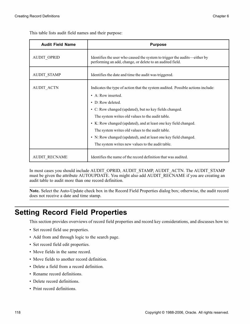
Creating Record Definitions Chapter 6
This table lists audit field names and their purpose:
Audit Field Name Purpose
AUDIT_OPRID Identifies the user who caused the system to trigger the audits—either byperforming an add, change, or delete to an audited field.
AUDIT_STAMP Identifies the date and time the audit was triggered.
AUDIT_ACTN Indicates the type of action that the system audited. Possible actions include:
• A: Row inserted.
• D: Row deleted.
• C: Row changed (updated), but no key fields changed.
The system writes old values to the audit table.
• K: Row changed (updated), and at least one key field changed.
The system writes old values to the audit table.
• N: Row changed (updated), and at least one key field changed.
The system writes new values to the audit table.
AUDIT_RECNAME Identifies the name of the record definition that was audited.
In most cases you should include AUDIT_OPRID, AUDIT_STAMP, AUDIT_ACTN. The AUDIT_STAMPmust be given the attribute AUTOUPDATE. You might also add AUDIT_RECNAME if you are creating anaudit table to audit more than one record definition.
Note. Select the Auto-Update check box in the Record Field Properties dialog box; otherwise, the audit recorddoes not receive a date and time stamp.
Setting Record Field PropertiesThis section provides overviews of record field properties and record key considerations, and discusses how to:
• Set record field use properties.• Add from and through logic to the search page.• Set record field edit properties.• Move fields in the same record.• Move fields to another record definition.• Delete a field from a record definition.• Rename record definitions.• Delete record definitions.• Print record definitions.
118 Copyright © 1988-2006, Oracle. All rights reserved.

Chapter 6 Creating Record Definitions
• Create SQL view and dynamic view Select statements.
Understanding Record Field PropertiesWhen you add a field to a record definition, you must define attributes for how the field is used in that record.These include key settings, default values, table edits, and PeopleCode programs.
The properties of record fields are not shared among records; they are specific to a single record definition andare stored with the record. Therefore, even though you might add the same field to multiple records, eachrecord stores a unique set of record field properties while the primary field definition remains the same.
When you access record field properties from a record definition, you set the record field properties—not fielddefinition properties or record definition properties.
To edit record field properties from a record definition, select Edit, Record Field Properties from thePeopleSoft Application Designer menu.
Understanding Record Key ConsiderationsWhen creating key fields in your record definition there are several guidelines to keep in mind.
Records With Multiple KeysYou can specify more than one field as a key to a record definition—that is, a record definition can havea compound key.
Defining compound key combinations
For example, the keys to the ABSENCE_HIST record definition are EMPLID, ABSENCE_TYPE, andBEGIN_DT. This means that an absence history can be created only once.
Keys on Parent and Child TablesIn some cases, you have a field in a table for which you want to allow multiple occurrences, in which case youcreate a subordinate or child table. For example, for employee reviews, an employee can be reviewed forperformance in multiple categories—organization skills, interpersonal skills, and so on. These categories andratings are stored in a separate child table, EE_REVIEW_RT, which is directly related to REVIEW_DT, theparent table that stores information about employee reviews.
The keys that you establish in a parent record definition determine which keys are required in child recorddefinitions. The child must have the same keys as the parent, plus one or more keys that uniquely identifyeach row:
Copyright © 1988-2006, Oracle. All rights reserved. 119
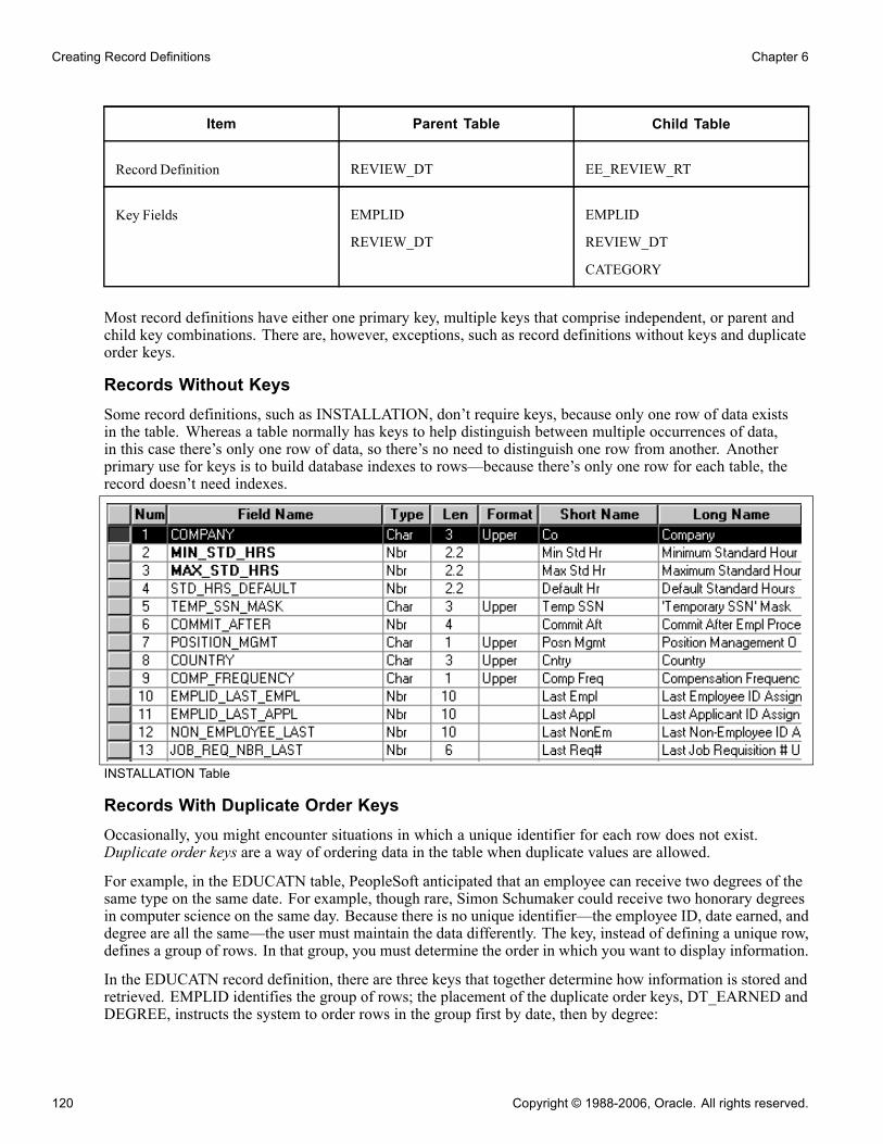
Creating Record Definitions Chapter 6
Item Parent Table Child Table
Record Definition REVIEW_DT EE_REVIEW_RT
Key Fields EMPLID
REVIEW_DT
EMPLID
REVIEW_DT
CATEGORY
Most record definitions have either one primary key, multiple keys that comprise independent, or parent andchild key combinations. There are, however, exceptions, such as record definitions without keys and duplicateorder keys.
Records Without KeysSome record definitions, such as INSTALLATION, don’t require keys, because only one row of data existsin the table. Whereas a table normally has keys to help distinguish between multiple occurrences of data,in this case there’s only one row of data, so there’s no need to distinguish one row from another. Anotherprimary use for keys is to build database indexes to rows—because there’s only one row for each table, therecord doesn’t need indexes.
INSTALLATION Table
Records With Duplicate Order KeysOccasionally, you might encounter situations in which a unique identifier for each row does not exist.Duplicate order keys are a way of ordering data in the table when duplicate values are allowed.
For example, in the EDUCATN table, PeopleSoft anticipated that an employee can receive two degrees of thesame type on the same date. For example, though rare, Simon Schumaker could receive two honorary degreesin computer science on the same day. Because there is no unique identifier—the employee ID, date earned, anddegree are all the same—the user must maintain the data differently. The key, instead of defining a unique row,defines a group of rows. In that group, you must determine the order in which you want to display information.
In the EDUCATN record definition, there are three keys that together determine how information is stored andretrieved. EMPLID identifies the group of rows; the placement of the duplicate order keys, DT_EARNED andDEGREE, instructs the system to order rows in the group first by date, then by degree:
120 Copyright © 1988-2006, Oracle. All rights reserved.
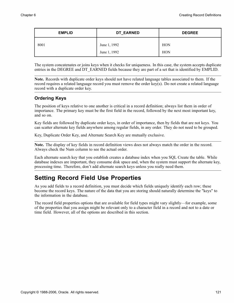
Chapter 6 Creating Record Definitions
EMPLID DT_EARNED DEGREE
8001 June 1, 1992
June 1, 1992
HON
HON
The system concatenates or joins keys when it checks for uniqueness. In this case, the system accepts duplicateentries in the DEGREE and DT_EARNED fields because they are part of a set that is identified by EMPLID.
Note. Records with duplicate order keys should not have related language tables associated to them. If therecord requires a related language record you must remove the order key(s). Do not create a related languagerecord with a duplicate order key.
Ordering KeysThe position of keys relative to one another is critical in a record definition; always list them in order ofimportance. The primary key must be the first field in the record, followed by the next most important key,and so on.
Key fields are followed by duplicate order keys, in order of importance, then by fields that are not keys. Youcan scatter alternate key fields anywhere among regular fields, in any order. They do not need to be grouped.
Key, Duplicate Order Key, and Alternate Search Key are mutually exclusive.
Note. The display of key fields in record definition views does not always match the order in the record.Always check the Num column to see the actual order.
Each alternate search key that you establish creates a database index when you SQL Create the table. Whiledatabase indexes are important, they consume disk space and, when the system must support the alternate key,processing time. Therefore, don’t add alternate search keys unless you really need them.
Setting Record Field Use PropertiesAs you add fields to a record definition, you must decide which fields uniquely identify each row; thesebecome the record keys. The nature of the data that you are storing should naturally determine the "keys" tothe information in the database.
The record field properties options that are available for field types might vary slightly—for example, someof the properties that you assign might be relevant only to a character field in a record and not to a date ortime field. However, all of the options are described in this section.
Copyright © 1988-2006, Oracle. All rights reserved. 121
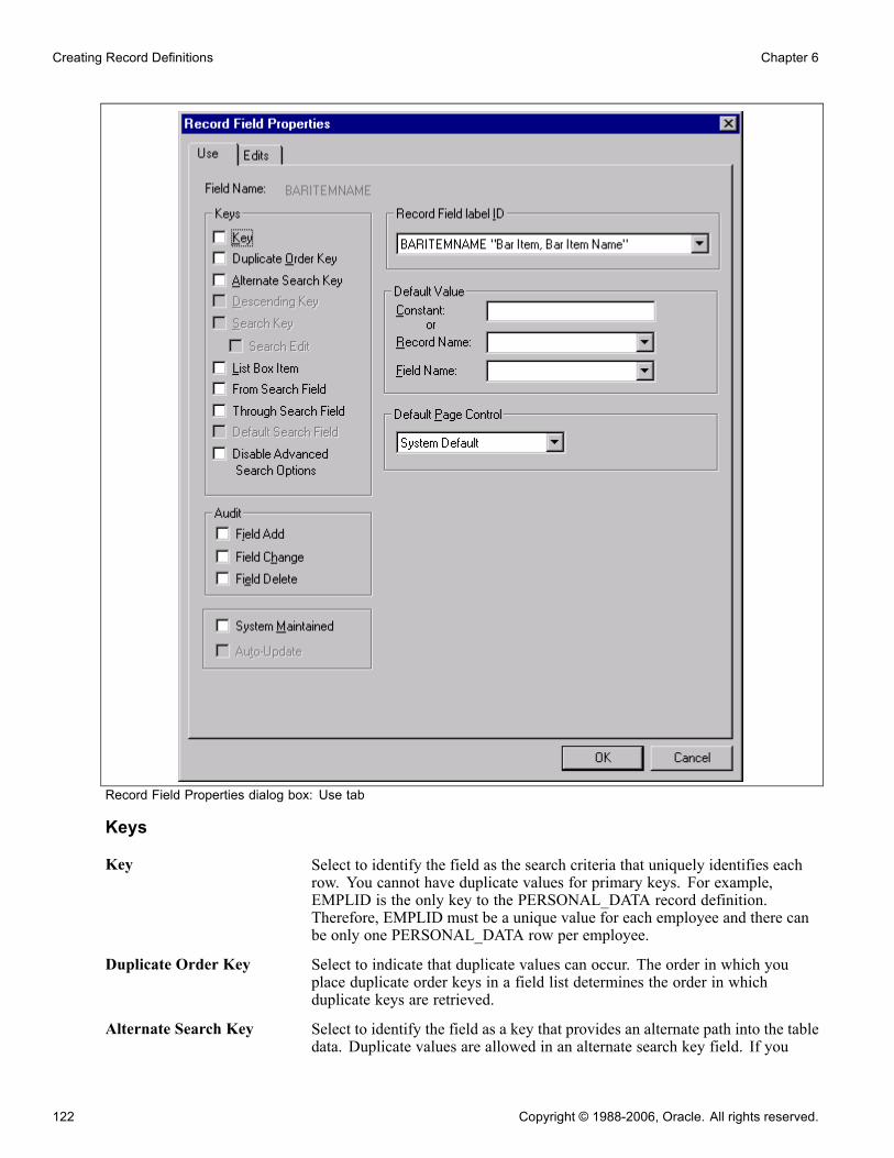
Creating Record Definitions Chapter 6
Record Field Properties dialog box: Use tab
Keys
Key Select to identify the field as the search criteria that uniquely identifies eachrow. You cannot have duplicate values for primary keys. For example,EMPLID is the only key to the PERSONAL_DATA record definition.Therefore, EMPLID must be a unique value for each employee and there canbe only one PERSONAL_DATA row per employee.
Duplicate Order Key Select to indicate that duplicate values can occur. The order in which youplace duplicate order keys in a field list determines the order in whichduplicate keys are retrieved.
Alternate Search Key Select to identify the field as a key that provides an alternate path into the tabledata. Duplicate values are allowed in an alternate search key field. If you
122 Copyright © 1988-2006, Oracle. All rights reserved.

Chapter 6 Creating Record Definitions
define a field as an alternate search key in a search record, when you bring upa page, the system prompts you to enter a key or alternate search key values.
Descending Key Select to identify the field as descending if you want rows of data to beretrieved in reverse alphanumeric order (for example, 3, 2, and 1). If youclear this check box, the key is ascending, meaning that rows are stored andretrieved in alphanumeric order (for example, 1, 2, and 3). This option appliesonly to a field that is specified as a key, duplicate order key, or alternate searchkey. PeopleSoft uses descending order primarily for effective date fields;most character keys are ascending.
Search Key Select to make the field available on the basic and advanced search or lookuppages. A search key is valid only for keys and should be used only in searchand prompt records. If you select this check box, the system automaticallyselects List Box Item.
Search Edit Enabled only if Search Key is selected. Selecting this option enforces therequired property and table edits on the search page. It also enforces theseedits under circumstances where the search page would normally be bypassed.With this option, the user no longer has the ability to perform partial searcheson this field.
List Box Item Select if you want the field to appear in the list box preceding a page. If a fieldhas values in the translate table and you designate it as a list box item, the listbox automatically shows the translated value instead of the code.
From Search Field andThrough Search Field
Select for fields that are used as search records. If you select From SearchField, the displayed list contains rows in which the field value is greaterthan or equal to a value that the user enters. If you select Through SearchField, the displayed list contains rows in which the field value is less than orequal to a value that the user enters.If you do not want these fields to be in a search list box, clear the List BoxItem check box, even if the field is an alternate search key.
Default Search Field Select to control which field name appears in the Search By drop-downlist box on the basic search page.
Disable Advanced SearchOptions
Select to prevent runtime search pages from displaying advanced searchfeatures for this field.
AuditThe audit options apply only to data that is manipulated on a normal PeopleSoft application page throughcomponent processing. These options do not apply to data that is added using SQLExec in PeopleCode orby some other means. PSAUDIT logs the user ID, the date and time the field was modified, and the oldand new values.
To audit certain fields, regardless of the record definitions in which they’re included, you want to control whenthe fields are audited. To audit several fields in a record definition, you might want to consider specifyingaudits at the record definition level.
Field Add Audits this field whenever a new row of data is added.
Field Change Audits this field whenever the contents are changed.
Field Delete Audits this field whenever a row of data is deleted.
Copyright © 1988-2006, Oracle. All rights reserved. 123

Creating Record Definitions Chapter 6
System Maintained Select to indicate that the field value is system-generated. This option is fordocumentation purposes only and doesn’t affect processing.
Auto-Update Select to have the field updated with the server’s current date and timewhenever a user creates or updates a row. Any user entries—even if permittedon a page—are overwritten by the server time.
Currency Control Field Enables the user to specify where to find the currency code that is used todisplay the currency symbol, decimal digits, and scale of a number field. Touse this option, the multicurrency option must be set. You might also want toenable the current display when you define the field on the page.
Record Field Label IDSpecify which label, long name or short name, to use for the record. The default value is ***Use DefaultLabel***. This enables you to change labels of record fields dynamically anytime that the default label onthe field definition is changed.
For example, if a field definition has three labels:
• Label1 (Long Name1, Short Name1), marked as default.• Label2 (Long Name2, Short Name2).• Label3 (Long Name3, Short Name3).
When the label ID in a record field is set to Use Default Label, initially the long name and short name are LongName1 and Short Name1. If the default label is changed to Label3 in the field definition, then the long nameand short name automatically become Long Name3 and Short Name3.
Default ValueSelect the most commonly used value as the default. You can always enter a different value if the default isinappropriate. The more defaults that you provide, the more data entry time you’ll save your users.
For a field, you can enter a default value as a system variable or as a combination of record and field names.
Constant Specify a default value.The value is case-sensitive. If the record has translate values for this field, thevalues appear in a drop-down list.You can specify a system variable only when you want to display the valueof the current date or time. The accepted system variables to be used asconstants are:
• %DATE for DATE, TIME, or DATETIME fields.• %TIME for TIME fields.• %DATETIME for DATETIME fields.• %CLIENTDATE for DATE, TIME, or DATETIME fields. Note that inthis case %CLIENTDATE is only relevant for a DATE field. Otherwiseit behaves the same as %DATE.
Record Name and FieldName
Enter the record and field names of the default value.
Default Page Control Specify the default appearance of a field as it appears on the page thatcorresponds with the record field that you are creating.
124 Copyright © 1988-2006, Oracle. All rights reserved.

Chapter 6 Creating Record Definitions
Time Zone and Related Date FieldsThese fields are enabled only if the current field is a time or date and time field. They determine whether thefield is displayed or entered in a specified time zone.
Specified Time Zone Times are always stored in a database base time zone, but when you placea time field on a page, you can display the time in the base time zone oranother time zone.If you clear this check box, the time appears in the database base time zone. Ifyou have users in multiple time zones, you can reduce confusion by showingthe time zone along with the time.If you select this check box, the system converts the time according to thetime zone specified in Time Zone Control Field. This control field must be afield in the current record. Set an appropriate default value for the timezone control field.
Date Control Field Select which related date field in the current record stores the calendar date towhich this field should be adjusted.
Typically, you want to make a date field a descending key so that the row with the latest and most current timeappears first. If you want the default value to be the current system date, enter the value %date (or %time)as the constant in the Default Values group box.
In general, each Time record field that is related to the Time Zone field should also be related to a Date field onthat same record. Otherwise, the time data that is displayed or saved may not properly reflect the appropriatestate of daylight savings in that time zone. Furthermore, each Time record field should be associated witha different Date record field.
For applications where two Time record fields need to share a common Date record field (as in, recordswith a start time and an end time always occurring on the same date), you can relate each Time record fieldto the same Date record field. However, keep in mind that the Date record field will only consider itselfassociated with one Time record field—the related Time record field that has the earliest position in the recordfield ordering for that record.
Adding From and Through Logic to the Search PageRefer to the following example when applying from and through logic to a search page.
CNT_CLAUSE_TBL record
Copyright © 1988-2006, Oracle. All rights reserved. 125

Creating Record Definitions Chapter 6
To apply the from and through logic to a search page:
1. Determine which component you want to change.
You must modify the search record for a particular page, so you must first identify the appropriatecomponent.
2. Determine on which field to use the from and through search logic.
Open the component in PeopleSoft Application Designer and examine the search record that is associatedwith the component. In the CNT_CLAUSE_TBL record, the search record is CNT_CLAUSE_TBL, andthe field to which you want to apply the from and through search logic is CONTRACT_CLAUSE.
3. Create a new view that contains the same fields as the original search record.
To use the from and through search logic, the search record must be a view. If the search record is alreadybased on a view, you can modify the existing view instead of creating a new view.
4. Select the From Search Field property for the field.
In the new view, select the from search field and apply the following record field properties: Key, SearchKey, and From Search Field (List Box Item is optional).
5. Create a new field with exactly the same attributes as the from field.
For example, if CONTRACT_CLAUSE represents the field from which you want to search, create a fieldcalled CONTRACT_CLAUSE_TO representing the field through which you want to search.
6. Insert the new field directly below the original field.
7. Select the Through Search Field property for the field.
Select the new through search field and apply the following record field properties: Key, Search Key, andThrough Search Field only.
8. Update the SQL view text.
Update the SQL view Select statement in the new view to reflect the new column. That is, the view textshould select the same field twice in a row (as shown in the example that follows this procedure). This isbecause the same field is used for the from logic and the through logic.
9. Save and build the new view.
10. Update the component properties.
You must update the search record so that the component uses the new view.
11. Test the new search page.
The search page should now include the new through field so that the user can specify a range of values forthe field. Because you want to search on both fields, you must use an advanced search.
The results in the list box should reflect a range of values between the from and through fields thatare specified. The results are inclusive—they include the minimum and maximum values that the userspecified.
Example of Updating the SQL View Select StatementOnce you define a search field as a Through Search Field, you’ll need to update the SQL view text.
126 Copyright © 1988-2006, Oracle. All rights reserved.

Chapter 6 Creating Record Definitions
Updating the SQL view Select statement
Setting Record Field Edit PropertiesThe Edits tab enables you to specify whether the system is to perform special edits or validations on a recordfield. You also name the record definition for the prompt table that stores values.
Required Select if you don’t want users to skip a field or leave it blank. Users are unableto save their work until they complete all of the required fields on a page.
Note. The system only checks required fields when the page field is changedor the record buffer is changed.
Edit Type
No Edit Select if you don’t want to edit the contents of this field against a table. This isthe default, which makes the options in the Table Edit group box unavailable.
Table Edit Select to edit the contents of the field against the values that are maintainedin the specified table. When you select Table Edit, the Type field becomesavailable in the Table Edit group box.
Table Edit
Type Select from the drop-down list box:Prompt Table with No Edit: Provides users with a list of suggested values, butdoes not edit the contents of the field against the prompt table. Users can enterany value. Selecting this option makes the Prompt Table field available.Prompt Table Edit: Edits the contents of the field against the values that aremaintained in the specified prompt table. Selecting this option activates thePrompt Table field. When you enter a prompt table name and exit the field bypressing TAB, Set Control Field becomes activated.Translate Table Edit: Edits the contents of the field against the translate table.The translate table stores values for fields that must be validated but don’t
Copyright © 1988-2006, Oracle. All rights reserved. 127

Creating Record Definitions Chapter 6
need individual tables of their own. If you select this option, Prompt Table andSet Control Field become unavailable.Yes/No Table Edit: Makes the values for this field Y (yes) and N (no) only. Ifyou select this option, Prompt Table and Set Control Field become unavailable.This is a 1/0 table edit where 1=True and 0=False.
Note. The list of available table edit types is dependent on the field type.
If you add a field (other than with the paste action) to a record and the fieldname is already defined in the database with previously defined translatevalues, the system automatically selects Table Edit and selects Translate TableEdit as the table type. For both Translate Table Edit and Yes/No Table Edit,PeopleSoft recommends that you follow its design standards, select Required,and specify a default value for the field in the Record Field Properties dialogbox.
Prompt Table Enter the name of the record definition that you want to use as the prompttable for this field.If you want the prompt table to vary depending on the context of the field,indicate a field in the derived or work record (DERIVED) that contains thename of the prompt table at runtime. Then, in this field enter%FieldName.The % is required, and indicates that you’re referencing a derived or workrecord definition named DERIVED. FieldName is the name of the field inthat DERIVED record definition.
Set Control Field Select a set control field that overrides the set control field of the recorddefinition specified in the prompt table. If you don’t specify a name in thisfield, the default is the set control field of the record definition specifiedin the prompt table.
Reasonable Date Select if you want the system to test the field value to determine whether itis within 30 days of the current date. If the date is out of range, a warningmessage appears when the user exits the field.
Moving Fields in the Same RecordYou can move fields in a record by dragging a field to another place in the open record definition. In addition,you can change the visible order of fields by clicking any of the grid headings.
128 Copyright © 1988-2006, Oracle. All rights reserved.

Chapter 6 Creating Record Definitions
Moving field to new position
To move a field in the same record definition:
1. Select the field that you want to move.Use the CTRL and SHIFT keys to select multiple fields at once.
2. Drag the selected field number to the new position in the record definition window.A red line between rows indicates the new placement options as you drag the field. The Num columnautomatically renumbers the fields in the new order.
Note. The fields are reordered only in the visible display of the record definition, not in the actual table.
Moving Fields to Another Record DefinitionTo move fields from one record definition to another, you can cut and paste the fields. You can also drag a fieldfrom the project workspace into a record definition in the object workspace or between open record definitions.
To move a field from one record definition to another:
1. Open the two records between which you want to move the field.2. Select the field that you want to move.Move multiple fields by using the CTRL or SHIFT keys.
3. Select Edit, Cut.If this is the correct field to cut from the record, click Yes.
4. Select the new position for the field in the destination record.5. Select Edit, Paste to paste the field into the new record definition.
Note. PeopleCode that is associated with fields is not carried over with cut and paste operations. The sameis true for delete and undo with field deletions in records. RecordField attributes, such as key, search key,and so on, are retained.
Deleting a Field From a Record DefinitionTo delete a field from a record definition:
1. Select the field that you want to remove and press the DEL (delete) key.
Copyright © 1988-2006, Oracle. All rights reserved. 129

Creating Record Definitions Chapter 6
This deletes the field completely and doesn’t copy it to the clipboard, unlike a cut operation, whichdoes copy to the clipboard.
2. When the system prompts you to confirm the deletion, click Yes.If you’ve already SQL Created the underlying table for the record definition from which you are deletingthe field, re-create the table, or use the SQL Alter function to alter the table.
Important! If you delete a field from a record definition, you must also delete it from any pages on whichit appears. When you delete a field, the system does not automatically delete references to the field inPeopleCode, so you must do this manually. To determine where the field is referenced in PeopleCode,use the Find Object References feature.
You can also reference the following two reports: "Fields and Records" (XRFFLRC) shows whichrecords contain the field; "Fields Referenced by PeopleCode Programs" (XRFFLPC) shows PeopleCodethat refers to the field in the record.
Modify or remove PeopleCode when you find references to the deleted field.
Renaming Record DefinitionsTo rename a record definition:
1. Select File, Rename.The Rename Definition dialog box appears.
2. Select Record from Definition Type.3. Click Rename.4. Select the record and click Rename.A rectangular box appears around the name.
5. Enter the new name and press ENTER.
Results of Renaming Record DefinitionsWhen you rename a record definition, the system automatically renames all references to it, including data ontables with columns named RECNAME where the data matches the record being renamed.
The only references that are not renamed are the text portion of SQL functions, such as SQLExec and ScrollSelect, and the record names in the view text. To find the text portion of SQL functions in PeopleCode orrecord names in view text, select Edit, Find In to search for the matching text.
If you have already SQL Created the underlying tables for the record definition that you renamed, re-createthat table. To preserve data in the tables, use the SQL Alter function to rename the database tables.
Deleting Record DefinitionsTo delete a record definition:
1. Select File, Delete.2. Select the record definition to delete.3. Click Delete.
130 Copyright © 1988-2006, Oracle. All rights reserved.

Chapter 6 Creating Record Definitions
Warning! When you delete a record definition, the system automatically deletes any PeopleCode that isassociated with the record.
4. Click Yes if you really want to delete the record definition.
Note. Notify your database administrator about which record definition you deleted, so that theadministrator can drop the underlying SQL table and its contents from the database.
Printing Record DefinitionsYou can print your record definitions as references identifying all of the fields and their various attributes—anyspecial use, edits, or PeopleCode that you’ve applied.
To print a record definition, it must be open in the object workspace.
To print a record definition:
1. Select File, Page Setup to change any of the print record defaults.The system retains your changes until you reset them again. The Page Setup dialog box appears.
2. Select printing options.
Definition Print a picture of what the definition looks like.
PeopleCode Select if you want the report to include a listing of any PeopleCodeprograms that are attached to each field, identifying the program type andlisting all of the PeopleCode statements. Selected by default.
Graphics Not used for record definition printing.
Margins(mm) Set the distance (in millimeters) from the edge of the page to the left, right,top, and bottom edges of the page image or report. The defaults are: 20(top), 5 (bottom), 5 (left), and 0 (right).
Header Print a header at the top of the report indicating the date and time at whichyou printed the report and the database name, record name, versionnumber, and page number. Selected by default.
Footer Print a footer at the bottom of the report indicating the date and time atwhich you printed the report and the database name, record name, versionnumber, and page number. Cleared by default.
Border Print a border or box around a record definition report. To print reportsfaster, clear this check box so that the printer can print the report incharacter mode, rather than in graphics mode. Cleared by default.
Border Space(mm) Insert a set amount of space between a graphical boarder around the recorddefinition report and the margins of the report. The default value is 3.
3. Click OK when you are done, to close the Print Setup dialog box and save your settings.4. Select File, Print.
Record Definition ReportThe following table lists the columns in the record definition report and their contents:
Copyright © 1988-2006, Oracle. All rights reserved. 131
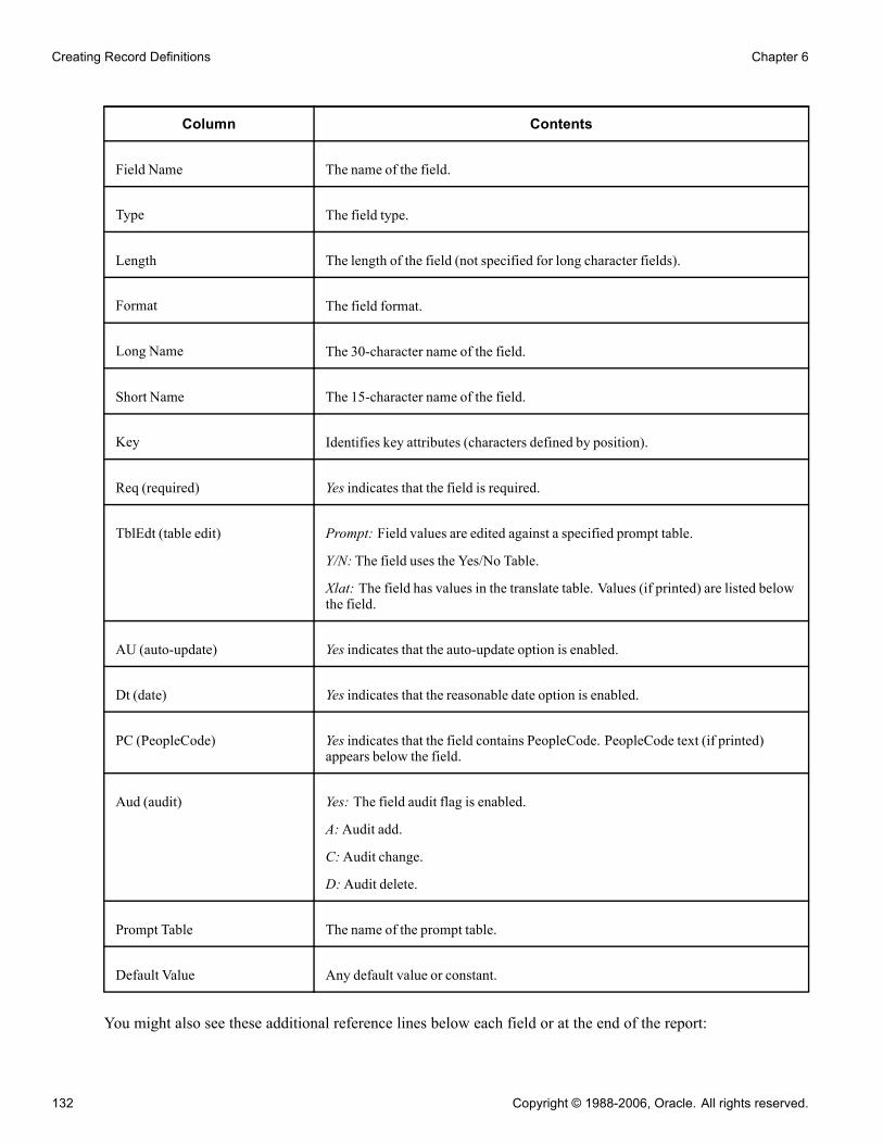
Creating Record Definitions Chapter 6
Column Contents
Field Name The name of the field.
Type The field type.
Length The length of the field (not specified for long character fields).
Format The field format.
Long Name The 30-character name of the field.
Short Name The 15-character name of the field.
Key Identifies key attributes (characters defined by position).
Req (required) Yes indicates that the field is required.
TblEdt (table edit) Prompt: Field values are edited against a specified prompt table.
Y/N: The field uses the Yes/No Table.
Xlat: The field has values in the translate table. Values (if printed) are listed belowthe field.
AU (auto-update) Yes indicates that the auto-update option is enabled.
Dt (date) Yes indicates that the reasonable date option is enabled.
PC (PeopleCode) Yes indicates that the field contains PeopleCode. PeopleCode text (if printed)appears below the field.
Aud (audit) Yes: The field audit flag is enabled.
A:Audit add.
C:Audit change.
D:Audit delete.
Prompt Table The name of the prompt table.
Default Value Any default value or constant.
You might also see these additional reference lines below each field or at the end of the report:
132 Copyright © 1988-2006, Oracle. All rights reserved.

Chapter 6 Creating Record Definitions
Reference Description
SQL View Shows the SQL view Select statement for view-type record definitions. Thisappears at the top of the report.
SystemMaintained Indicates that the SystemMaintained check box is selected. Because this option isfor documentation purposes only, it doesn’t warrant its own column heading.
DbField Help Context: nnn Indicates that the field has been assigned a field help context number to link it to ahelp file that describes how the field is used wherever it appears in the database.
RecField Help Context: nnn Indicates that the field has been assigned to a record field help context number tolink it to a help file that describes how the field is used only as it appears in thisrecord definition.
Audit Record Identifies a user-defined audit record. Lists the audit record name and the typeof audit.
Set Control Field Identifies a set control field that is designated for the record definition.
Related Language Record Identifies a related language record that is designated for the record definition.
Query Security Record Identifies views that are used to restrict query access to data that is stored in thetable.
Parent Record Name Identifies the hierarchical relationship of the record for query reporting.
Printing records with subrecords takes into account whether the record view is expanded or collapsed. If therecord view is expanded, the subrecord fields are indented to the appropriate level of nesting.
Creating SQL View and Dynamic View Select StatementsIf you are creating a SQL view or dynamic view record definition, you must enter a SQL view Select statement,to indicate which field values you want to join from which tables. The only difference between the standardview and dynamic view is that the dynamic view is not defined as a view to the database—it is stored on theclient and run as a Select at runtime. Dynamic views avoid some constraints on views on some platforms.
Non-Standard SQLTable Name (nonstandardStructured Query Languagetable name)
Override the standard convention of prefixing PS_ to the record name.
Build Sequence No (buildsequence number)
Set the order in which the dynamic view is to be created. The default value is1 when the record or view is initially created. Views that must be createdfirst can be set to 0, while views that you want created last can be set to 1or greater. The build sequence number is stored with the other details ofthe record or view in the database.
Copyright © 1988-2006, Oracle. All rights reserved. 133
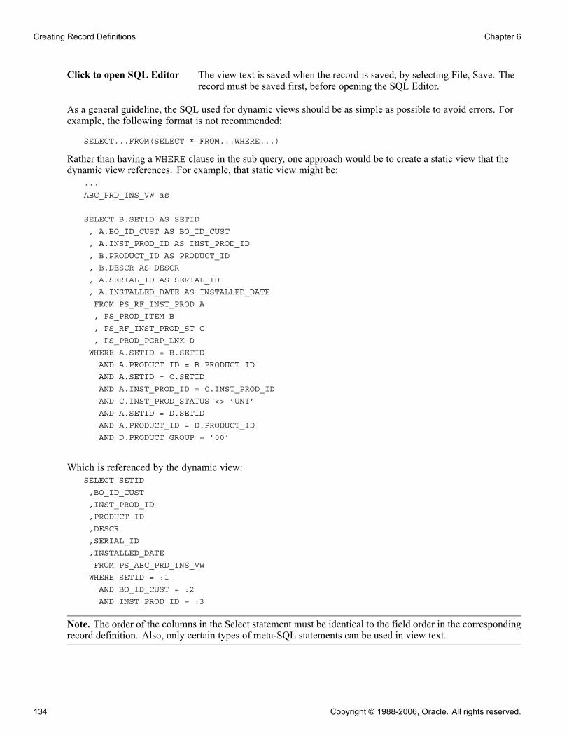
Creating Record Definitions Chapter 6
Click to open SQL Editor The view text is saved when the record is saved, by selecting File, Save. Therecord must be saved first, before opening the SQL Editor.
As a general guideline, the SQL used for dynamic views should be as simple as possible to avoid errors. Forexample, the following format is not recommended:
SELECT...FROM(SELECT * FROM...WHERE...)
Rather than having a WHERE clause in the sub query, one approach would be to create a static view that thedynamic view references. For example, that static view might be:
...
ABC_PRD_INS_VW as
SELECT B.SETID AS SETID
, A.BO_ID_CUST AS BO_ID_CUST
, A.INST_PROD_ID AS INST_PROD_ID
, B.PRODUCT_ID AS PRODUCT_ID
, B.DESCR AS DESCR
, A.SERIAL_ID AS SERIAL_ID
, A.INSTALLED_DATE AS INSTALLED_DATE
FROM PS_RF_INST_PROD A
, PS_PROD_ITEM B
, PS_RF_INST_PROD_ST C
, PS_PROD_PGRP_LNK D
WHERE A.SETID = B.SETID
AND A.PRODUCT_ID = B.PRODUCT_ID
AND A.SETID = C.SETID
AND A.INST_PROD_ID = C.INST_PROD_ID
AND C.INST_PROD_STATUS <> ’UNI’
AND A.SETID = D.SETID
AND A.PRODUCT_ID = D.PRODUCT_ID
AND D.PRODUCT_GROUP = ’00’
Which is referenced by the dynamic view:SELECT SETID
,BO_ID_CUST
,INST_PROD_ID
,PRODUCT_ID
,DESCR
,SERIAL_ID
,INSTALLED_DATE
FROM PS_ABC_PRD_INS_VW
WHERE SETID = :1
AND BO_ID_CUST = :2
AND INST_PROD_ID = :3
Note. The order of the columns in the Select statement must be identical to the field order in the correspondingrecord definition. Also, only certain types of meta-SQL statements can be used in view text.
134 Copyright © 1988-2006, Oracle. All rights reserved.

Chapter 6 Creating Record Definitions
See AlsoChapter 7, “Administering Data,” Using Cross-Platform Meta-SQL for Dynamic Views, page 173
Copyright © 1988-2006, Oracle. All rights reserved. 135

Creating Record Definitions Chapter 6
136 Copyright © 1988-2006, Oracle. All rights reserved.

CHAPTER 7
Administering Data
This chapter provides an overview of the PeopleSoft Application Designer data administration and the Build processand discusses how to:
• Use the Build menu.• Create tables.• Create indexes.• Alter tables.• Create triggers.• Create views.• Administer DDL.
Understanding Data Administration and the Build ProcessUsing PeopleSoft Application Designer, you create several kinds of definitions that represent databasecomponents. For instance, field definitions represent table columns, and record definitions represent tablesand views. From these field and record definitions, you can create tables, views, and indexes. The importantconcept to remember is that the definitions are just the blueprints for the actual, physical database componentswith which they are associated. In the context of the entire application development cycle, use the Build processto create Structured Query Language (SQL) tables, views, triggers, and indexes occurs after you define newfields and create the record definitions. After you build the SQL tables, you begin creating page definitions.
After you create and define your field and record definitions, you must create or build the underlying SQLtables that house the application data that your users enter online in your production environment. This buildprocess is the centerpiece of the data administration features in PeopleSoft Application Designer. The Buildprocess uses Data Definition Language (DDL) to construct a physical database component that is based on theassociated record and field definitions that you created. With the build feature, you can create the following:
• Tables• Indexes• Views• Triggers
You can also use the build feature to alter existing tables if you change the record definition after the tablealready exists. Altering a table is useful, because it enables you to make changes without losing the applicationdata that is already housed in the table. In general, the results of the build operation are written to a script filethat a database administrator can run later. On some database platforms, you can run the SQL online, if youprefer, so that your changes are immediately reflected in the physical database. However, if you run the SQLimmediately, you cannot review it to make sure that the table that was built truly meets all of your requirements.
Copyright © 1988-2006, Oracle. All rights reserved. 137
Administering Data Chapter 7
Before you begin using the data administration tools and running a build process, make sure to:
• Review what DDL means for PeopleSoft applications.
• Grant build authority.
Reviewing DDLDDL is the part of SQL that pertains to the creation of tables, indexes, views, triggers, and tablespaces. DDL isalso the part of SQL that differs most between the various relational database platforms. Each database vendorprovides different syntax and configuration options for creating and organizing tables and for optimizingperformance. Because PeopleTools supports multiple database platforms, PeopleSoft has designed a flexibleway of specifying DDL that enables you to take advantage of each vendor’s features. The basic components ofthe PeopleSoft DDL support include the following:
• DDL model definition: A complete set of the supported DDL statements for each database platform.
Statements include Create Table, Create Tablespace, and Create Index. Each DDL model statement hassubstitution parameters that can be specified at the database level or overridden for individual records.
• Record DDL: Specify the DDL model substitution parameters for an individual record.
• Index DDL: Specify the DDL model substitution parameters for an index.
• Sizing sets: A way to maintain multiple versions of your DDL model statements for a database platform.
For example, you can use one sizing set during a development phase, when tables have only test data, andanother during production, when tables have much more data.
Granting Build AuthorityPeopleSoft Security enables you to specify which users can build scripts, run scripts (Execute SQL now),maintain DDL, and so on. Access Security from the PeopleTools link in the menu.
See AlsoEnterprise PeopleTools 8.48 PeopleBook: Security Administration, “Setting Up Permission Lists,” SettingPeopleTools Permissions
Running the Build ProcessThis section provides an overview of the Build menu and discusses how to:
• Select the build scope.• Select build options and run the Build process.
Understanding the Build MenuAccess all of the commands and options that are associated with building tables, views, indexes, triggers,and altering tables from the Build menu. When you choose to build an item from the Build menu, the tasksfor creating or running SQL scripts that define the underlying database components are included in theBuild dialog box.
138 Copyright © 1988-2006, Oracle. All rights reserved.
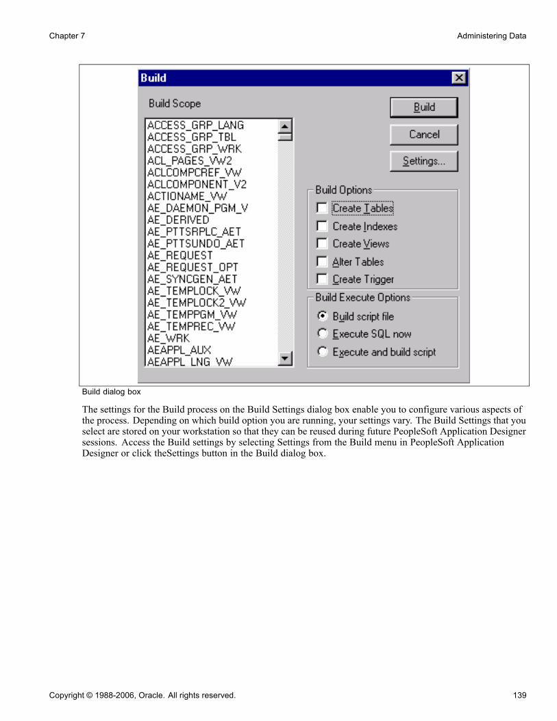
Chapter 7 Administering Data
Build dialog box
The settings for the Build process on the Build Settings dialog box enable you to configure various aspects ofthe process. Depending on which build option you are running, your settings vary. The Build Settings that youselect are stored on your workstation so that they can be reused during future PeopleSoft Application Designersessions. Access the Build settings by selecting Settings from the Build menu in PeopleSoft ApplicationDesigner or click theSettings button in the Build dialog box.
Copyright © 1988-2006, Oracle. All rights reserved. 139
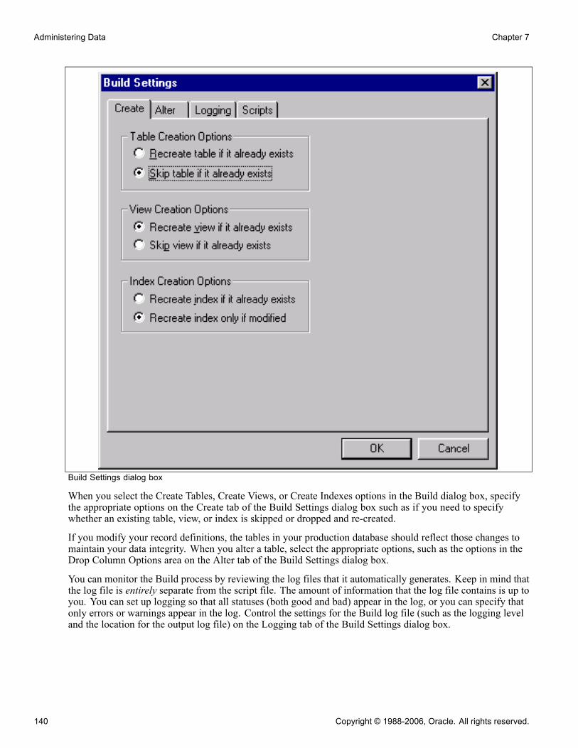
Administering Data Chapter 7
Build Settings dialog box
When you select the Create Tables, Create Views, or Create Indexes options in the Build dialog box, specifythe appropriate options on the Create tab of the Build Settings dialog box such as if you need to specifywhether an existing table, view, or index is skipped or dropped and re-created.
If you modify your record definitions, the tables in your production database should reflect those changes tomaintain your data integrity. When you alter a table, select the appropriate options, such as the options in theDrop Column Options area on the Alter tab of the Build Settings dialog box.
You can monitor the Build process by reviewing the log files that it automatically generates. Keep in mind thatthe log file is entirely separate from the script file. The amount of information that the log file contains is up toyou. You can set up logging so that all statuses (both good and bad) appear in the log, or you can specify thatonly errors or warnings appear in the log. Control the settings for the Build log file (such as the logging leveland the location for the output log file) on the Logging tab of the Build Settings dialog box.
140 Copyright © 1988-2006, Oracle. All rights reserved.

Chapter 7 Administering Data
If you build a script file, then the Build process generates a script file that contains all of the CREATE andALTER SQL statements so that you can review them before running the SQL through another SQL commandprocessor. If the generated script file meets your requirements, a database administrator (DBA) can runthe script later. The Build process can produce multiple scripts during a single run—one for each buildoption—depending on the script settings that you specify at runtime. For example, you can specify that theBuild process generate a separate script for your tables, views, indexes, triggers, and alters, or you can have allof the SQL for each action contained in one script. Use the Scripts tab of the Build Settings dialog box tospecify where the SQL script is written, whether you want multiple scripts generated for each definition type,and whether you want previous scripts overwritten.
Selecting the Build ScopeThe Build feature includes three different scopes that determine the size of your build project. Depending onwhat you actually want to build—one record or an entire project—you can determine this by selecting oneof the scopes described in the following sections.
Current DefinitionSelect Current Definition from the Build menu to build or alter the active record definition. Active definitionmeans the definition that is currently active in the definition workspace.
ProjectSelect Project from the Build menu to build or alter all of the records, indexes, triggers, and views in thecurrent project—that is, all of the records that appear in the project workspace. You typically find numerousrecord definitions in the Build Scope list box.
To build all definitions in a database, create a new project and insert all of the appropriate records. Forexample, insert records of a particular type, such as views. If you create another record after the all recordsproject is built, you must manually add the new record to the project.
You may also build a project using the command line and specific parameters. The prerequisites for usingthe command line to build a project are:
• The project exists with all objects.
• The build settings need to be set in the Windows registry.
Note. The Build Project process accesses every single record that is in the project, including work records,even if they are marked to be deleted.
Select Definitions Into ProjectIn some situations, you might want to build a subset of the records in the project that is currently open. Ifyou do not want to build an entire project or even the current project, you can build only the definitions thatyou select in the project workspace by pressing the CTRL key and selecting multiple records in the projectworkspace. After you select the appropriate records, right-click and select Build from the pop-up menu. Onlythe definitions that are selected in the project workspace appear in the Build Scope list box.
Note. You must invoke the Build process from the pop-up menu; you cannot build selected definitions froman open project using the Build menu.
Selecting Build Options and Running the Build ProcessAccess the Build dialog box.
Copyright © 1988-2006, Oracle. All rights reserved. 141
Administering Data Chapter 7
Build Scope This list box displays all of the definitions that are included in the currentBuild process. The records that appear in this list box cannot be selected orcleared. If you must narrow the scope of your build, do so before accessing theBuild dialog box.
Build Click this button to start the Build process. While the Build process is running,the Build Progress dialog box appears, showing the current record beingprocessed, the record number being processed in the series, and the totalnumber of records that comprise the build. To stop a running Build process,click the Cancel button. When the Build process completes, the Cancel buttonis unavailable and the Close button is the only valid button.
Settings Click this button to open the Build Settings dialog box, where you can view orchange your options.
Note. After the Build process begins, there are no runtime prompts until the process is complete. All eventsare written to the Build log.
Build OptionsThe Build Options group box enables you to specify what action you want to occur: Create Tables, CreateIndexes, Create Views, Alter Tables, or Create Trigger. If you select Create Tables or Alter Tables, CreateIndexes is automatically selected by default. Also, if you select Alter Tables, Create Indexes and CreateTrigger are automatically selected by default.
Note. You can select both Alter Tables and Create Tables to run concurrently, as long as the Skip table if italready exists option is enabled on the Create tab in the Build Settings dialog box. Otherwise, there is no wayto determine whether you wanted to alter or re-create a table that already exists.
Build Execute Options
Build script file Select this option to review and update the SQL before running the script.This is the safest method.
Execute SQL now (executeStructured Query Languagenow)
Select this option if you don’t want to invoke another program to run the SQL;the SQL runs as part of the Build process. The disadvantage with runningthe SQL immediately is that you have no opportunity to review the SQLbefore it is committed to the database.
Execute and build script Select this option to review the SQL that the Build process just ran.
To run the SQL script file that the Build process generates, you must use a third-party SQL interpreter, such asOracle SQL*Plus or Microsoft ISQL/W. Most database vendors include a native command processor thatyou can run on the client or the server.
Note. The Execute SQL now option is unavailable if you use the Alter Tables Build option. However, you canuse the Execute and build script option when using Alter Tables. Selecting this option builds a script withthe entire alter SQL. This script may help if errors are encountered during the alter process. However, ifthere are multiple tables in an alter process and an error occurs, the errors are reported to a log file andthe process continues to the next table.
Using Command Line Syntax to Build a ProjectUse the same command line syntax as identified previously to build a project.
142 Copyright © 1988-2006, Oracle. All rights reserved.

Chapter 7 Administering Data
See Chapter 18, “Using Command Line Parameters,” Understanding PeopleSoft Application DesignerCommand Line Parameters, page 413.
Use the command line statement for the project build to:
• Connect the project to the source database.• Use the build settings from the Windows registry to generate the SQL script for the create or alter processes.
Before running the build command line, verify that:
• The project’s system components are created and loaded.
• The build options are set in the Windows registry.
Available ParametersThis table lists all of the available parameters for the project build statement:
Parameter Description Error Handling
-HIDE Use to hide the PeopleSoftApplication Designer interface.Always use this parameter whenperforming a command line Copyprocess.
Required for all project commandline processes.
-CT Database type.
Enter the type of the databaseto which you are connecting(MICROSFT, ORACLE, SYBASE,and so on).
Required. If you do not supply thisparameter, the last database type istaken from the registry. If it fails, theprocess stops and error messages arewritten to the log file.
-CS Server name.
Enter the name of the sourcedatabase server for the database towhich you are connecting.
Required for some database types. Ifyou do not supply this parameter, theprocess stops and error messages arewritten to the log file.
-CD Database name.
Enter the name of the sourcedatabase to which you areconnecting, as you would enterit into the PeopleSoft Login dialogbox.
Required. If you do not supply thisparameter, the process stops anderror messages are written to the logfile.
-CO User ID.
Enter the PeopleSoft user ID thatis needed to sign in to the sourcedatabase.
Required. If you do not supply thisparameter, the last database type istaken from the registry. If it fails, theprocess stops and error messages arewritten to the log file.
Copyright © 1988-2006, Oracle. All rights reserved. 143
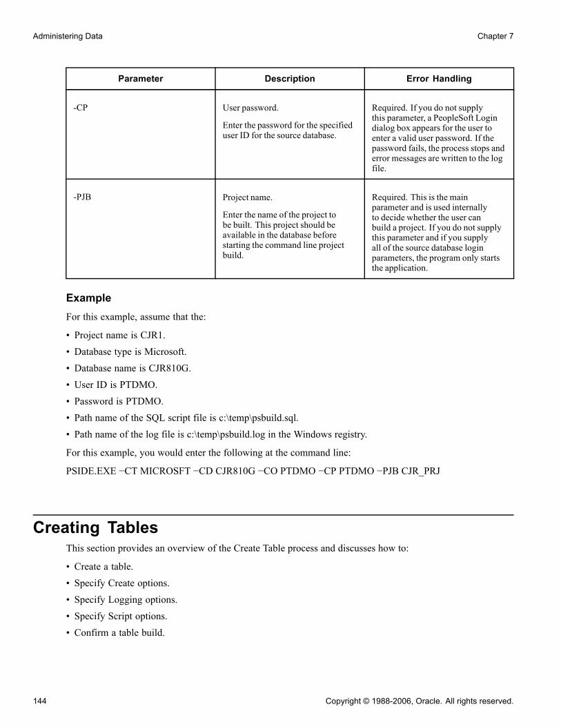
Administering Data Chapter 7
Parameter Description Error Handling
-CP User password.
Enter the password for the specifieduser ID for the source database.
Required. If you do not supplythis parameter, a PeopleSoft Logindialog box appears for the user toenter a valid user password. If thepassword fails, the process stops anderror messages are written to the logfile.
-PJB Project name.
Enter the name of the project tobe built. This project should beavailable in the database beforestarting the command line projectbuild.
Required. This is the mainparameter and is used internallyto decide whether the user canbuild a project. If you do not supplythis parameter and if you supplyall of the source database loginparameters, the program only startsthe application.
ExampleFor this example, assume that the:
• Project name is CJR1.• Database type is Microsoft.• Database name is CJR810G.• User ID is PTDMO.• Password is PTDMO.• Path name of the SQL script file is c:\temp\psbuild.sql.• Path name of the log file is c:\temp\psbuild.log in the Windows registry.
For this example, you would enter the following at the command line:
PSIDE.EXE −CT MICROSFT −CD CJR810G −CO PTDMO −CP PTDMO −PJB CJR_PRJ
Creating TablesThis section provides an overview of the Create Table process and discusses how to:
• Create a table.• Specify Create options.• Specify Logging options.• Specify Script options.• Confirm a table build.
144 Copyright © 1988-2006, Oracle. All rights reserved.

Chapter 7 Administering Data
Understanding the Create Table ProcessThe Build process generates the appropriate SQL Create statements to build tables based on both your recorddefinition and your platform. It prefaces each new application SQL table with PS_ to identify it as anapplication that was built using PeopleTools. For example:
PS_ABSENCE_HIST
Note. PeopleTools does not preface table names with PS_ if you specified a custom name in the Non-StandardSQL Table Name edit box located on the Type tab of the Record Properties dialog box.
The Build process also creates the appropriate indexes. Because long character fields operate more efficientlyin some database environments when they’re located at the end of the table, the Build process automaticallypositions long character fields at the end of the table for each database environment.
The Create Table process creates a new application table based on parameters defined in the record definition.When a new table is created, the database management system updates the system catalog tables to reflectthe attributes of the new table.
The Create Table process is illustrated by the following figure:
SystemCatalog Tables
ApplicationData Tables
PeopleToolsTables
A. Create the application datatable and indexes based on recorddefinition parameters.
B. Update the system catalogtables to reflect the newapplication data table and indexes.
B.A.
Database Server
Create Table process
After you build an updated SQL build script and run it, the PeopleTools tables and the system catalog tablesare synchronized; the record definition and the application data table are synchronized. The following tablelists the steps of the Create Table process and the associated record definition parameters:
Copyright © 1988-2006, Oracle. All rights reserved. 145
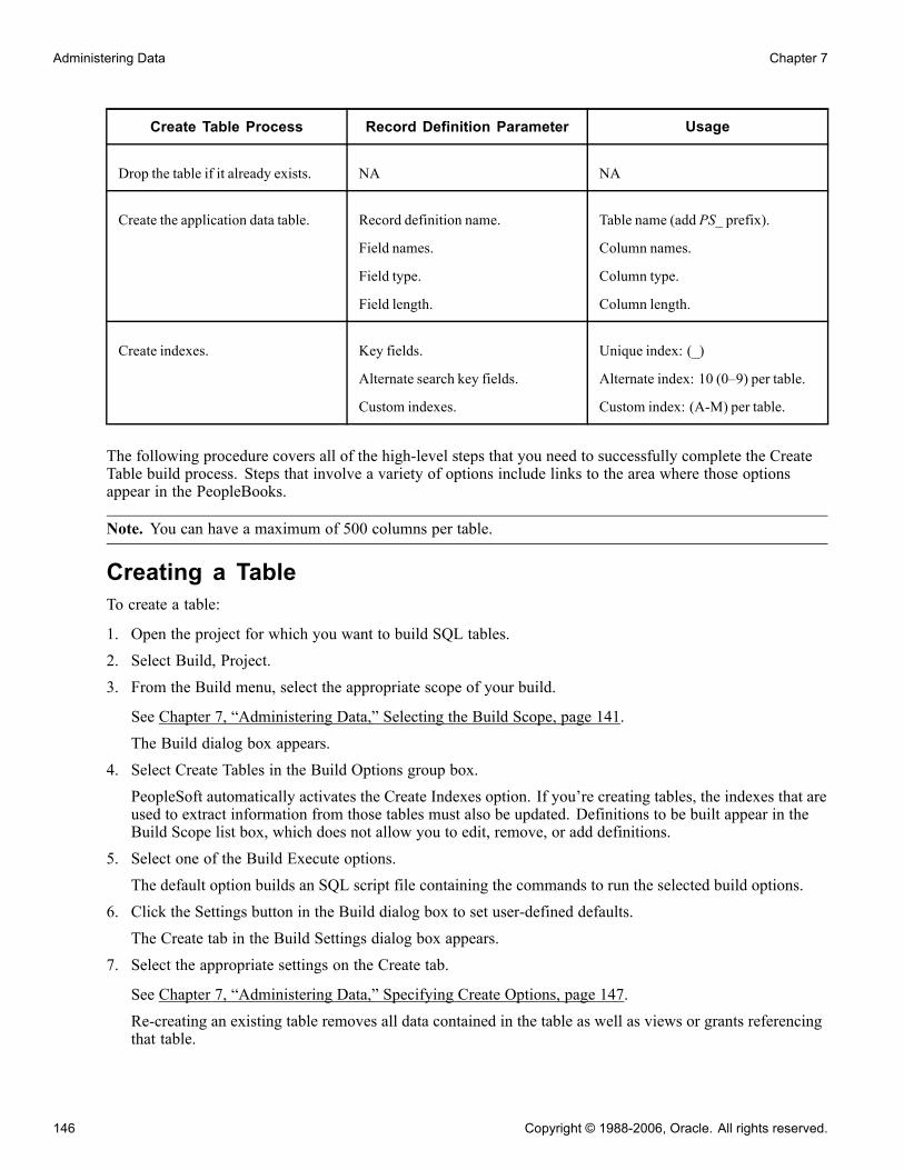
Administering Data Chapter 7
Create Table Process Record Definition Parameter Usage
Drop the table if it already exists. NA NA
Create the application data table. Record definition name.
Field names.
Field type.
Field length.
Table name (add PS_ prefix).
Column names.
Column type.
Column length.
Create indexes. Key fields.
Alternate search key fields.
Custom indexes.
Unique index: (_)
Alternate index: 10 (0–9) per table.
Custom index: (A-M) per table.
The following procedure covers all of the high-level steps that you need to successfully complete the CreateTable build process. Steps that involve a variety of options include links to the area where those optionsappear in the PeopleBooks.
Note. You can have a maximum of 500 columns per table.
Creating a TableTo create a table:
1. Open the project for which you want to build SQL tables.2. Select Build, Project.3. From the Build menu, select the appropriate scope of your build.
See Chapter 7, “Administering Data,” Selecting the Build Scope, page 141.The Build dialog box appears.
4. Select Create Tables in the Build Options group box.PeopleSoft automatically activates the Create Indexes option. If you’re creating tables, the indexes that areused to extract information from those tables must also be updated. Definitions to be built appear in theBuild Scope list box, which does not allow you to edit, remove, or add definitions.
5. Select one of the Build Execute options.The default option builds an SQL script file containing the commands to run the selected build options.
6. Click the Settings button in the Build dialog box to set user-defined defaults.The Create tab in the Build Settings dialog box appears.
7. Select the appropriate settings on the Create tab.
See Chapter 7, “Administering Data,” Specifying Create Options, page 147.
Re-creating an existing table removes all data contained in the table as well as views or grants referencingthat table.
146 Copyright © 1988-2006, Oracle. All rights reserved.

Chapter 7 Administering Data
8. Select the Logging tab.9. Set the Logging Levels and associated options.
See Chapter 7, “Administering Data,” Specifying Logging Options, page 148.
10. Select the Scripts tab.
11. Specify the script file options.
If you selected Execute SQL Now as your build option in the Build dialog box, you can skip the Scriptstab, because you will be running the SQL online. Settings on the Scripts tab are relevant only if youare building a SQL script to run later.
See Chapter 7, “Administering Data,” Specifying Script Options, page 152.12. Click OK to close the Build Settings dialog box.13. In the Build dialog box, click the Build button to run your build option.The length of a build process depends on the number of definitions that require building. Watch theBuild Progress dialog box to monitor the Build process. When the process completes, check any errorslisted in the log file.
Specifying Create OptionsAccess the Build Settings dialog box. Select the Create tab.
Build Settings dialog box: Create tab
Table Creation OptionsThese options determine when a table should and should not be created.
Copyright © 1988-2006, Oracle. All rights reserved. 147
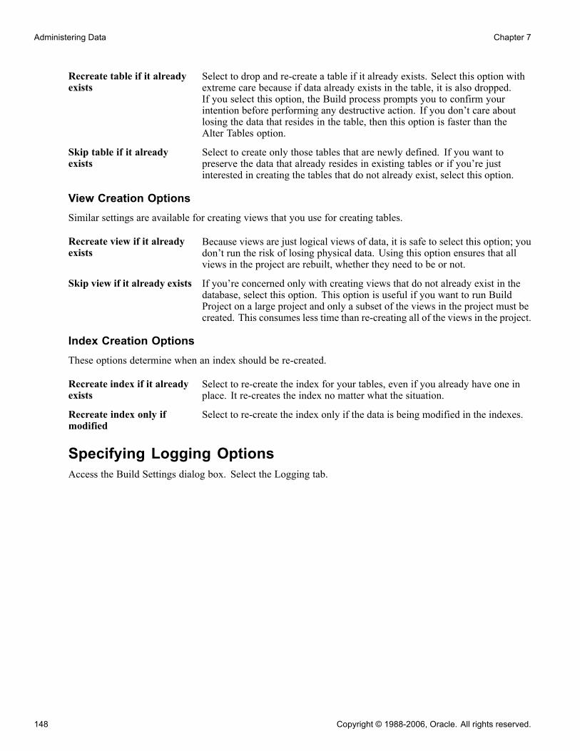
Administering Data Chapter 7
Recreate table if it alreadyexists
Select to drop and re-create a table if it already exists. Select this option withextreme care because if data already exists in the table, it is also dropped.If you select this option, the Build process prompts you to confirm yourintention before performing any destructive action. If you don’t care aboutlosing the data that resides in the table, then this option is faster than theAlter Tables option.
Skip table if it alreadyexists
Select to create only those tables that are newly defined. If you want topreserve the data that already resides in existing tables or if you’re justinterested in creating the tables that do not already exist, select this option.
View Creation OptionsSimilar settings are available for creating views that you use for creating tables.
Recreate view if it alreadyexists
Because views are just logical views of data, it is safe to select this option; youdon’t run the risk of losing physical data. Using this option ensures that allviews in the project are rebuilt, whether they need to be or not.
Skip view if it already exists If you’re concerned only with creating views that do not already exist in thedatabase, select this option. This option is useful if you want to run BuildProject on a large project and only a subset of the views in the project must becreated. This consumes less time than re-creating all of the views in the project.
Index Creation OptionsThese options determine when an index should be re-created.
Recreate index if it alreadyexists
Select to re-create the index for your tables, even if you already have one inplace. It re-creates the index no matter what the situation.
Recreate index only ifmodified
Select to re-create the index only if the data is being modified in the indexes.
Specifying Logging OptionsAccess the Build Settings dialog box. Select the Logging tab.
148 Copyright © 1988-2006, Oracle. All rights reserved.

Chapter 7 Administering Data
Build Settings dialog box: Logging tab
Logging LevelSpecify the detail of information that you want in your Build log output.
Fatal errors only Select this option if you want to see only the operations that failed.
Fatal errors and warnings Select this option to add warnings to the fatal errors.
Fatal errors, warnings andinformational messages
Select this option to see everything that processed successfully and all ofthe errors and warnings.
Note. These options are personal preferences and do not affect the actual build of your SQL tables, but theymight help you track down potential failures. For example, if you’re processing a large number of definitions,you’ll want to see only the operations that failed. Whereas, if you’re processing a small number of definitions,you’ll want to see all of the successful operations too.
Logging OutputSpecify where and in what form you want to view your log output.
Log to output window Select to write the same information that appears in the log file to thePeopleSoft Application Designer output window. Always be aware of thelevel that you select. If there is a lot of detail (high logging level plus manyrecords to process), it might be easier to copy the logging information to afile and print it later.
Copyright © 1988-2006, Oracle. All rights reserved. 149

Administering Data Chapter 7
Log to file Select to write the log to a file. If you select this check box, you can specify alocation and name for your log file in the Log file name edit box. To searchfor a name, click the Browse button. Select a .LOG type file from the BuildFile Selection dialog box. If you do not select this check box, the edit box isunavailable for entry.
Log settings Select to write all of the runtime options to the log. If you select this checkbox, it is not necessary to rerun a test when you have a problem. Should it benecessary to report a problem with the Build process or troubleshoot, it isimportant to know the settings that were active.
Note. PeopleSoft recommends selecting the Log to file check box and the Log to output window with aminimum logging level of fatal errors and warnings. In case you run into a problem, you already have theinformation that is needed to research the problem. Otherwise, you must run the process again with a higherlogging level.
Example Log ResultsThe following are samples of the type of information that you can expect to see in your log output thatcorresponds to the selections that you make on the Logging tab:
• Fatal errors:
SQL Build process began on 7/30/2003 at 8:46:46 PM for database
OM51U20
Error: BI_BILL_BY_F_VW - Unable to retrieve current DDL space name.
Alter processed failed. (76,47)
Error: BI_CHARGE_VW - Unable to retrieve current DDL space name.
Alter processed failed. (76,47)
Error: PS_BI_CYCLE_VW - alter failed due to an unknown column type
(UNDEFINED) found for field BILL_CYCLE_ID. (76,22)
Error: PS_BI_IVCLAYOUT_VW - alter failed due to an unknown column
type (UNDEFINED) found for field INVOICE_LAYOUT_ID. (76,22)
Error: CARINA - alter failed because SQL table does not exist. (76,7)
SQL Build process ended on 7/30/2003 at 8:54:34 PM.
2487 records processed, 11 errors, 0 warnings
SQL Build script for all processes written to file C:\TEMP\step38.SQL.
SQL Build log file written to C:\TEMP\step38.LOG
• Warnings:
SQL Build process began on 8/27/2003 at 4:00:32 PM for database DXD7L
Warning: ABSENCE_HIST2 - data would be truncated by altering
REASON. Record processed. (76,24)
• Fatal errors, warnings, and informational messages:
SQL Build process began on 8/27/2003 at 3:58:58 PM for database DXD7L
Warning: ABSENCE_HIST2 - data would be truncated by altering
REASON. Record processed. (76,24)
Error: ABSENCE_HIST2 - field PAID_UNPAID to be deleted has data
present. Record skipped. (76,23)
Informational: ACCOMPLISHMT_VW - view created and scripted
successfully. (76,18)
150 Copyright © 1988-2006, Oracle. All rights reserved.
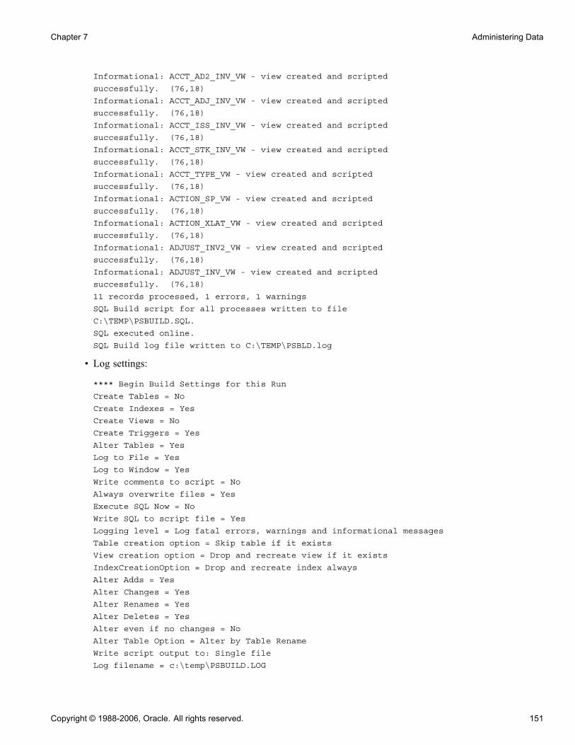
Chapter 7 Administering Data
Informational: ACCT_AD2_INV_VW - view created and scripted
successfully. (76,18)
Informational: ACCT_ADJ_INV_VW - view created and scripted
successfully. (76,18)
Informational: ACCT_ISS_INV_VW - view created and scripted
successfully. (76,18)
Informational: ACCT_STK_INV_VW - view created and scripted
successfully. (76,18)
Informational: ACCT_TYPE_VW - view created and scripted
successfully. (76,18)
Informational: ACTION_SP_VW - view created and scripted
successfully. (76,18)
Informational: ACTION_XLAT_VW - view created and scripted
successfully. (76,18)
Informational: ADJUST_INV2_VW - view created and scripted
successfully. (76,18)
Informational: ADJUST_INV_VW - view created and scripted
successfully. (76,18)
11 records processed, 1 errors, 1 warnings
SQL Build script for all processes written to file
C:\TEMP\PSBUILD.SQL.
SQL executed online.
SQL Build log file written to C:\TEMP\PSBLD.log
• Log settings:
**** Begin Build Settings for this Run
Create Tables = No
Create Indexes = Yes
Create Views = No
Create Triggers = Yes
Alter Tables = Yes
Log to File = Yes
Log to Window = Yes
Write comments to script = No
Always overwrite files = Yes
Execute SQL Now = No
Write SQL to script file = Yes
Logging level = Log fatal errors, warnings and informational messages
Table creation option = Skip table if it exists
View creation option = Drop and recreate view if it exists
IndexCreationOption = Drop and recreate index always
Alter Adds = Yes
Alter Changes = Yes
Alter Renames = Yes
Alter Deletes = Yes
Alter even if no changes = No
Alter Table Option = Alter by Table Rename
Write script output to: Single file
Log filename = c:\temp\PSBUILD.LOG
Copyright © 1988-2006, Oracle. All rights reserved. 151

Administering Data Chapter 7
Single script filename = c:\temp\PSBUILD.SQL
Alter drop column option = skip record if data present
Alter truncate column option = skip record if data would be truncated
Target database platform = MICROSFT
Target sizing set = 0
Working With the Output WindowYou can navigate from error messages in the PeopleSoft Application Designer output window to thecorresponding record definition by selecting the appropriate line in the Build log and double-clicking anywhereon that line. PeopleSoft Application Designer opens the corresponding record in the definition workspace.
Also, you can double-click any line in the output window that corresponds to a file—not just a record.PeopleSoft Application Designer opens that file with whatever application that you defined to open files with aparticular extension. For example, if you associated SQL files with your native SQL command utility, yourSQL utility opens and loads your PSBUILD.SQL script when you double-click the line that reads:
Single script file name = C:\TEMP\PSBUILD.SQL
Note. PeopleSoft Application Designer uses the standard Microsoft Windows method for defining whichprograms are associated with particular file types. To modify the file associations, open My Computer, selectView, Folder Options, and then select the File Types tab.
Specifying Script OptionsAccess the Build Settings dialog box. Select the Scripts tab.
Build Settings dialog box: Scripts tab
152 Copyright © 1988-2006, Oracle. All rights reserved.

Chapter 7 Administering Data
CommentsThe Write Alter comments to script check box enables you to either include or suppress alter comments. Thefollowing example displays the types of comments that you see in your PSALTER.SQL script if you enablethis option:
-- Alters for record PS_AE_RUN_CONTROL ;
-- AE_THREAD - change ;
-- OPRID - change ;
-- Start the Transaction ;
-- Data Conversion ;
-- Drop Old Indexes ;
DROP INDEX SYSADM.PS_AE_RUN_CONTROL
/
-- Add Columns ;
ALTER TABLE PS_AE_RUN_CONTROL ADD Z_TMP_ALTER_1 DECIMAL(12,4)
/
ALTER TABLE PS_AE_RUN_CONTROL ADD Z_TMP_ALTER_2 CHAR(12)
/
UPDATE PS_AE_RUN_CONTROL SET
Z_TMP_ALTER_1 = AE_THREAD,
Z_TMP_ALTER_2 = OPRID
/
If you do not view the alter comments, the script containing the same commands as the previous scriptlooks like this:
DROP INDEX SYSADM.PS_AE_RUN_CONTROL
/
ALTER TABLE PS_AE_RUN_CONTROL ADD Z_TMP_ALTER_1 DECIMAL(12,4)
/
ALTER TABLE PS_AE_RUN_CONTROL ADD Z_TMP_ALTER_2 CHAR(12)
/
UPDATE PS_AE_RUN_CONTROL SET
Z_TMP_ALTER_1 = AE_THREAD,
Z_TMP_ALTER_2 = OPRID
/
Script FileThe default for the Save as Unicode check box is based on the UNICODE/ANSI database. This check box isavailable only when using MSSQLServer, Oracle, DB2/UDB for Linux, UNIX, and Windows, Sybase andDB2 UDB for OS/390 and z/OS databases. Only on Informix , the check box is permanently unavailable,because the script files are always ANSI.
The following table explains the default settings for the Save as Unicode check box:
Copyright © 1988-2006, Oracle. All rights reserved. 153
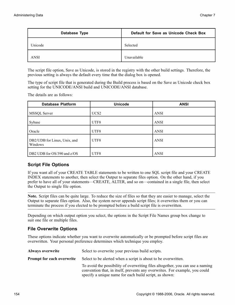
Administering Data Chapter 7
Database Type Default for Save as Unicode Check Box
Unicode Selected
ANSI Unavailable
The script file option, Save as Unicode, is stored in the registry with the other build settings. Therefore, theprevious setting is always the default every time that the dialog box is opened.
The type of script file that is generated during the Build process is based on the Save as Unicode check boxsetting for the UNICODE/ANSI build and UNICODE/ANSI database.
The details are as follows:
Database Platform Unicode ANSI
MSSQL Server UCS2 ANSI
Sybase UTF8 ANSI
Oracle UTF8 ANSI
DB2/UDB for Linux, Unix, andWindows
UTF8 ANSI
DB2 UDB for OS/390 and z/OS UTF8 ANSI
Script File OptionsIf you want all of your CREATE TABLE statements to be written to one SQL script file and your CREATEINDEX statements to another, then select the Output to separate files option. On the other hand, if youprefer to have all of your statements—CREATE, ALTER, and so on—contained in a single file, then selectthe Output to single file option.
Note. Script files can be quite large. To reduce the size of files so that they are easier to manage, select theOutput to separate files option. Also, the system never appends script files; it overwrites them or you canterminate the process if you elected to be prompted before a build script file is overwritten.
Depending on which output option you select, the options in the Script File Names group box change tosuit one file or multiple files.
File Overwrite OptionsThese options indicate whether you want to overwrite automatically or be prompted before script files areoverwritten. Your personal preference determines which technique you employ.
Always overwrite Select to overwrite your previous build scripts.
Prompt for each overwrite Select to be alerted when a script is about to be overwritten.To avoid the possibility of overwriting files altogether, you can use a namingconvention that, in itself, prevents any overwrites. For example, you couldspecify a unique name for each build script, as shown:
154 Copyright © 1988-2006, Oracle. All rights reserved.
Chapter 7 Administering Data
• C:\TEMP\PSINDEX1.SQL• C:\TEMP\PSINDEX2.SQL
Script File NamesThe options available to select in this group box depend on your selection in the Script File Options group box.
Output to single file When you select this option, an edit box appears in the Script File Namesgroup box: All Output File Name. The default name for the generated scriptis PSBUILD.SQL.
Note. Script files can be quite large. To reduce the size of files so that they areeasier to manage, select the Output to separate files option. Also, the systemnever appends script files; it overwrites them or you can terminate the processif you elected to be prompted before a build script file is overwritten.
Output to separate files If you select this option, the following edit boxes appear—one for eachbuild option:
• Create Table File Name: The default name for this script is PSTABLE.SQL.
• Create Index File Name: The default name for this script is PSINDEX.SQL.
• Create Trigger File Name: The default name for this script isPSTRIGGER.SQL.
• Create View File Name: The default name for this script is PSVIEW.SQL.
• Alter Table File Name: The default name for this script is PSALTER.SQL.
Copyright © 1988-2006, Oracle. All rights reserved. 155
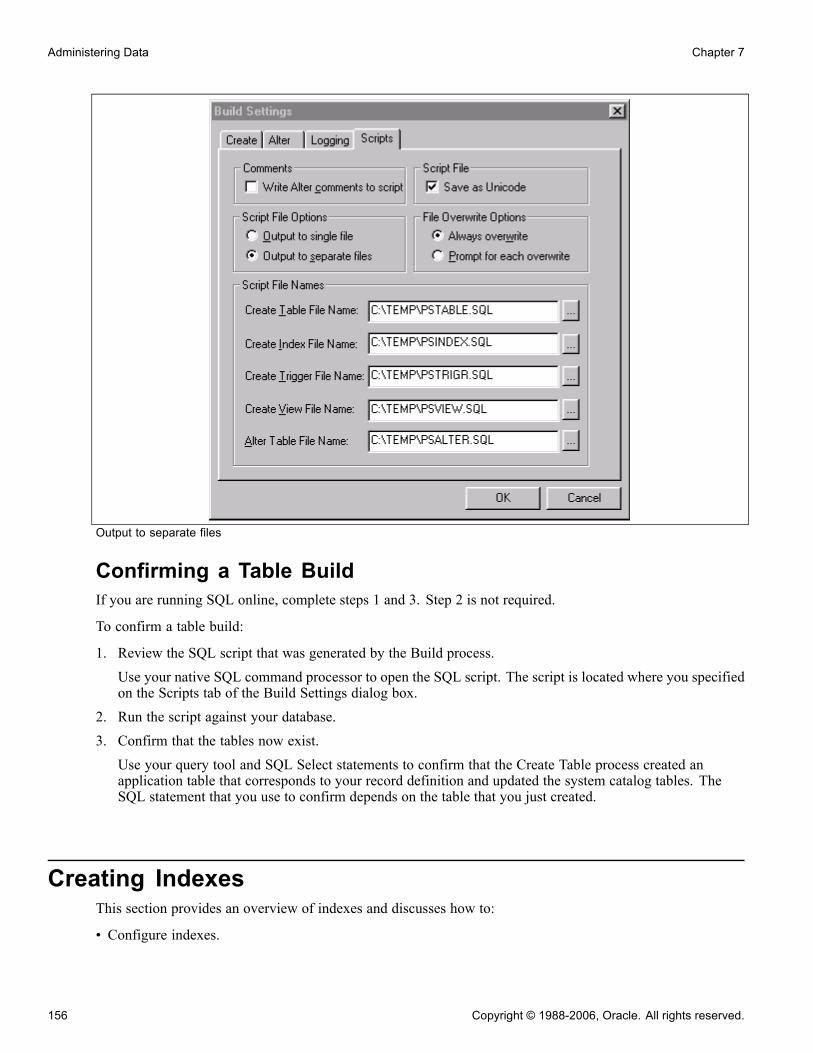
Administering Data Chapter 7
Output to separate files
Confirming a Table BuildIf you are running SQL online, complete steps 1 and 3. Step 2 is not required.
To confirm a table build:
1. Review the SQL script that was generated by the Build process.Use your native SQL command processor to open the SQL script. The script is located where you specifiedon the Scripts tab of the Build Settings dialog box.
2. Run the script against your database.3. Confirm that the tables now exist.Use your query tool and SQL Select statements to confirm that the Create Table process created anapplication table that corresponds to your record definition and updated the system catalog tables. TheSQL statement that you use to confirm depends on the table that you just created.
Creating IndexesThis section provides an overview of indexes and discusses how to:
• Configure indexes.
156 Copyright © 1988-2006, Oracle. All rights reserved.

Chapter 7 Administering Data
• Add a custom index.• Edit the DDL.
Understanding IndexesIndexes are an important part of your physical database, because they affect the efficiency and speed withwhich your application can store and retrieve data. PeopleSoft application indexes are defined in two ways.
Some indexes are defined for you automatically, based on the key, search key, list box items, and alternatesearch keys that you specified on your record definition. These indexes are used by the application processorfor quick access when you use the online system.
However, it is sometimes necessary to define additional indexes to improve the performance of demandingqueries, reports, or batch programs. These additional indexes are defined and modified using the dataadministration tools in PeopleSoft Application Designer.
Note. You can only create indexes for record definition types that are SQL or temporary tables. You would notcreate indexes on views, such as a SQL view, because views are never physically created. The Indexes optionin the Tools, Data Administration menu is disabled when a view is open.
When you use SQL Create or SQL Alter on a table, the system automatically builds database indexes to theSQL table that are based on the keys and list items that you specify in the record definition. Your database usesindexes to find definitions in the database the same way that you use indexes to find specific information in abook. If an index entry exists for a specific field on a table, the database can search and quickly find what itneeds to complete your request; otherwise, it must search through the contents of the entire table.
Indexes enhance system performance by generating key lists that the application processor uses to extract thedata that it uses to populate pages and search records. The system automatically creates:
• Standard indexes (key or duplicate order key indexes), if at least one field in the table is a key or duplicateorder key.The index contains all key and duplicate order key fields. The system automatically names this indexwith a prefix of PS_.
• Alternate search key indexes for each alternate search key.The system automatically names this index with a prefix of PSn, in which n is a number between 0 and 9.
• Custom indexes, which can be defined with the Edit Index, Edit DLL, and Add Index dialog box in thePeopleSoft Application Designer administration tools.The system automatically names this index with a prefix of Psa, in which a can be any letter between A andM. Custom indexes are not automatically created.
For most database tables (those with unique keys), the key index defines unique keys for a table, but the systemalso uses it to access high-level keys and orders by all keys. The alternate search key indexes support thesearch record and field prompts. The purpose of these different indexes is to enable the system to respond toall system prompts through index-only SQL access, minimizing direct database table access.
Copyright © 1988-2006, Oracle. All rights reserved. 157
Administering Data Chapter 7
Note. If you are using Create Table or Alter, the Create Index option is automatically selected. With the CreateTable or Alter options, you can’t clear the Create Index option.
The alter process takes care of indexes regardless of the Alter Table Options you select on the Alter tab of theBuild Settings dialog box. In the case of "Alter by Table Rename," the indexes are dropped automaticallywhen the temp table is dropped. For the "Alter in Place" option, the index creation process goes through the"Recreate index only if modified" option on the Create tab.
When creating indexes with the Alter method, prior to altering the table, drop the statistics using "DROPSTATISTICS" that were created explicitly on columns using "CREATE STATISTICS."
The following record definition modifications require the creation of new indexes:
• Add, delete, or modify keys, duplicate order keys, alternate search keys, or descending keys in the RecordField Properties dialog box.
• Change the order of keys (ascending, as opposed to descending) in the Change Record Indexes dialog box.• Change the Unique or Clustersettings in the Edit Index dialog box.
Platform Support for IndexesMost database platforms support indexes with an unlimited number of keys. However, Microsoft SQL Server2000, DB2/UDB for Linux, UNIX, and Windows, and Informix support only indexes that have a maximum of16 keys. PeopleSoft supports indexes for these databases by creating functional indexes. If a record definitionhas more than 16 keys, the Build process automatically alters the table to support functional indexes. Thesystem adds a warning message to the log file indicating this. Sample code for functional indexes for eachof these platforms can be found in Appendix A of this PeopleBook.
See Appendix A, “Understanding Functional Indexes,” page 529.
The following list offers more detail on functional indexes by database platform:
• Functional indexes for Microsoft SQL Server 2000.If an index has more than 16 keys, the key fields are concatenated to a functional key. This key fieldis then added to the table as the last column called MSSCONCATCOL. A unique index is created forMSSXCONCATCOL as well as an additional index called PSW<record name> that is used as a search index.
• Functional indexes for DB2/UDB for Linux, UNIX, and Windows.Similar to the concatenation that occurs with SQL Server, DB2/UDB for Linux, UNIX, and Windows alsoconcatenates the key fields to a functional key. The key is then added to the table as the last column calledDBXCONCATCOL. A unique index is created for DBXCONCATCOL as well as an additional index calledPSW<record name> that is used as a search index.
• Functional indexes for Informix.For Informix, if there are more than 16 keys in an index, a function is created for every 16 keys. The namefor this set of 16 keys is PS_<record name>_SP<the incremented number for each function>. The functionsare used to create a unique index. An additional index called PSW<record name> is also created.
Configuring IndexesFor performance tuning, you might want to change the order of your index keys. PeopleSoft ApplicationDesigner provides direct control over all of the indexes created by PeopleTools. You can inspect, add, orchange all defined indexes or delete custom indexes for any record in the system through the Change RecordIndexes dialog box.
158 Copyright © 1988-2006, Oracle. All rights reserved.

Chapter 7 Administering Data
Standard indexes are based on the key, duplicate order key, or alternate search key only. However, with theChange Record Indexes dialog box, you can modify those indexes and create additional indexes, which mightbe required if you do custom processing. Any of the indexes that you entered can be maintained for alldatabase platforms or for a list of specific platforms. All indexes and keys created by PeopleTools are storedin PeopleSoft system tables.
Change Record Indexes dialog box
To edit the index key order:
1. Open the record definition for which you want to make the custom index.
2. Select Tools, Data Administration, Indexes to access the Change Record Indexes dialog box.
The Custom Order column indicates whether the index keys have been configured. The default selection isN, indicating that no configurations have been made.
3. Double-click the N or Y in the Custom Order column for the index that you want to alter, or click Edit Index.
4. Select the Custom Key Order check box.
5. Click OK.
The Custom Order entry changes from N to Y.
6. Drag and drop the field that you want to move into the appropriate order.
After configuring the key order, to reset the key order of the index to the original order as defined in therecord definition, clear the Custom Order entry (Y to N), and click OK. The orders of the key fields resetto the original position in the Change Record Indexes dialog box.
7. Check the key order in the Use Display mode of your record definition.
The Num (number) column represents the original order of the keys in your record and the Ordr (order)column reflects the key order in the index.
8. Create the indexes:
Copyright © 1988-2006, Oracle. All rights reserved. 159
Administering Data Chapter 7
a. Select Build, Current Project.b. Select Create Indexes in the Build Options group box.
Make sure that you select the appropriate build settings.
9. Run the Build process to either generate a script or run the SQL online.10. Confirm the construction of the new index with your native SQL command processor.
Note. Users might also configure indexes for "parent" records that contain one or more subrecords withoutkey fields, such as the subrecord ADDRESS_SBR. However, if the subrecords contain key fields, indexkey order changes are restricted. The Custom Key Order option is deactivated and cannot be changed fromN to Y. Change the index key order for the parent before inserting the subrecord.
Adding a Custom IndexTo add an index:
1. Open the record.
2. Select Tools, Data Administration, Indexes to access the Change Record Indexes dialog box.
3. Click Add Index.
The Add Index dialog box enables you to determine for which database platforms you want to definethe index if you selected the Some option for Platform. The Custom Key Order check box has beenselected by the system to ensure that the underlying record definition is not adversely impacted by thechange to your index.
For all user-defined indexes, you must enter a description of the index in the Comments section. Itis useful to know the purpose of the index, the transactions and processes that use this index, and otherrelevant information. This information assists you when you want to remove unused indexes. An errormessage appears if you do not do so.
Note. You cannot add more than 22 user indexes (A-V). The system disables the Add Index button if therecord already contains 22 user indexes.
4. Indicate the database platforms for which you want to create the index.5. Click the OK button to add a row to the Change Record Indexes dialog box and enable the arrow buttons.6. Move the field under the new index row:
a. In the Record Fields list box, select the field that you want indexed.b. Click the arrow button, or double-click the field.c. Repeat this step for each field that you want to add.
7. Click OK.8. Save the record definition.9. Select Build, Current Project.10. Select Create Indexes under Build Options.Make sure that you select the appropriate build settings.
11. Run the Build process to either generate a script or run SQL online.12. Run the generated SQL script if you opted to generate one.
160 Copyright © 1988-2006, Oracle. All rights reserved.
Chapter 7 Administering Data
13. Confirm the construction of the new index with your native SQL command processor.
Editing the DDLIn the Change Record Indexes dialog box, you can view the DDL for the index and override DDL parametersthat are defined in the DDL model for this index.
To edit the DDL:
1. In the Change Record Indexes dialog box, select the index that you want to edit.2. Click the Edit DDL button to access the Maintain Index DDL dialog box.The upper list box in this dialog box lists the platform and DDL parameter, and the lower list box showsthe DDL templates for the various platforms. Your database might have fewer platforms enabled. Thesizing set enables different collections of tables to have different model statements and parameters.
3. Select the platform and sizing set.4. Click View DDL.The dialog box that appears shows the index DDL for the platform and sizing set that you selected.Review this DDL statement.
5. Click the Close button when you’re finished.6. Select the parameter that you want to edit in the upper list box.The default value is set in the DDL Model Defaults dialog box. You can change this setting by selectingGo, PeopleTools, Utilities, Use, DDL Model Defaults in PeopleSoft Application Designer, or by selectingPeopleTools, Utilities, Use, DDL Model Defaults in the browser.
7. Click the Edit Parm (edit parameter) button to access the Edit Override Parm Value (edit overrideparameter value) dialog box.
8. Enter the override value for the parameter that you selected.9. Select OK for both open dialog boxes.
Altering TablesThis chapter provides an overview of the Alter process and discusses how to:
• Determine tables to be altered after a field change.• Alter a table.• Specify alter options.• Confirm your table alter.
Understanding the Alter ProcessThe Alter process enables you to make changes to your record definitions at any time without losing theapplication data that is already housed in the table. To ensure that the Alter process produces the appropriateresults, be aware of when to alter an existing table and what types of conversions PeopleSoft ApplicationDesigner supports. To preserve data that is stored in tables and also reflect a recent change in the tabledefinition, use the alter tables function to make the appropriate changes.
Copyright © 1988-2006, Oracle. All rights reserved. 161

Administering Data Chapter 7
The alter function simplifies the process of modifying database tables when new data fields are added or whenexisting data fields are modified. It effectively eliminates the need to write SQL statements to performthe same function.
PeopleSoft specifically designed the alter process to automate the task of writing alter scripts and protect theintegrity of your database. In essence, it protects your interests by ensuring that you always control data loss.The alter function performs tests that verify whether data will be lost during the conversion on each column tobe altered. Data loss normally occurs when reducing the character width of a column, dropping a column thatcontains data, or converting a number field to a character field that is too small.
The generated statements for this method are sent to a SQL script file—the alter script. After the script hascompleted, you are responsible for reapplying any SQL table DDL that you applied outside of PeopleTools.Typically, this consists of GRANT and REVOKE statements controlling security.
Note. On Oracle databases, procedural language/Structured Query Language (PL/SQL) is required to usethe PeopleSoft Application Designer Build process.
Alter SettingsThe Alter tab in the Build Settings dialog box handles the most common types of data conversions, including:
• Increasing the length of character fields.• Changing a character (CHAR) field to a long character (LONG VARCHAR) field.• Increasing the size of number or character fields.• Reducing the decimal positions in number fields.If any column of the table has data that will be lost when truncating, the system action is determined bythe Change Column Length options.
• Changing integer-only number fields to character fields, where the character field is formatted with leadingzeros.If any column of the table has a number that does not fit in the new character field, system action isdetermined by the Change Column Length options. This prevents data from being lost.
• Adding columns to SQL tables.• Dropping columns from SQL tables.• Renaming columns in SQL tables.• Renaming SQL tables.• Moving tables to a new tablespace.
The following sections describe the types of alter conversions that you can expect to occur during the Buildprocess.
Data ConversionsWhen altering tables with existing field data, PeopleSoft Application Designer handles conversions as outlinedin the following table. A No indicates that conversion cannot take place. A number in the cell following aYes indicates that there are restrictions involved with the conversion. Refer to the corresponding numberednote following the table for additional information:
162 Copyright © 1988-2006, Oracle. All rights reserved.
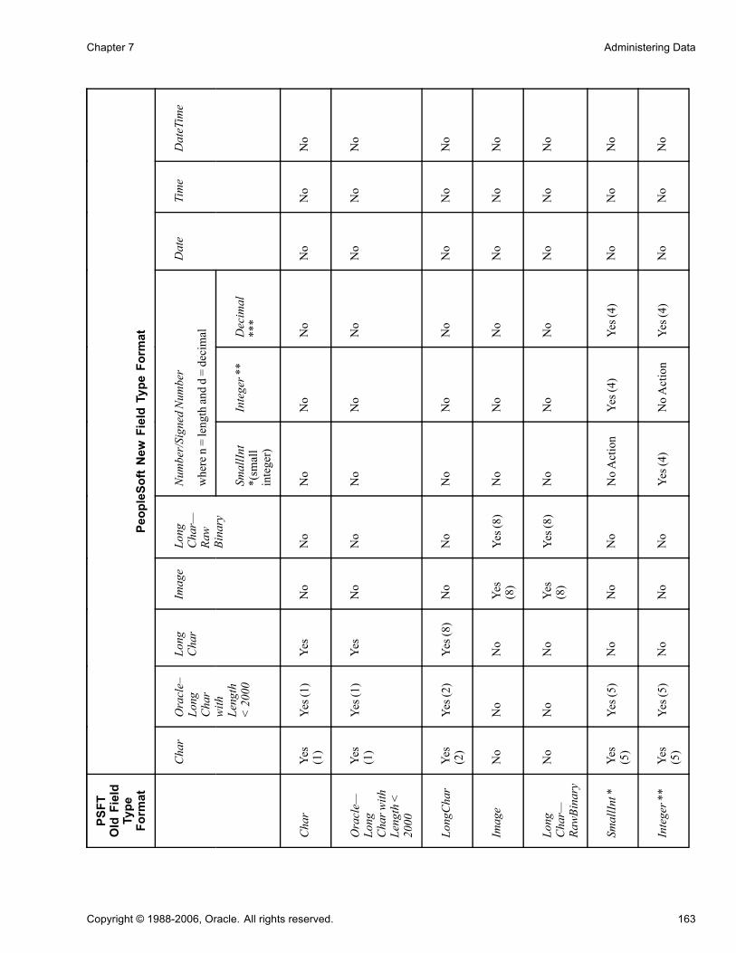
Chapter 7 Administering Data
PSFT
OldField
Type
Format
PeopleSoftNew
FieldType
Format
Number/SignedNumber
wheren=lengthandd=decimal
Char
Oracle–
Long
Char
withLength
<2000
Long
Char
Image
Long
Char—
Raw
Binary
SmallInt
*(small
integer)
Integer**
Decimal
***
Date
Time
DateTime
Char
Yes
(1)
Yes(1)
Yes
No
No
No
No
No
No
No
No
Oracle—
Long
Charwith
Length<
2000
Yes
(1)
Yes(1)
Yes
No
No
No
No
No
No
No
No
LongChar
Yes
(2)
Yes(2)
Yes(8)
No
No
No
No
No
No
No
No
Image
No
No
No
Yes
(8)
Yes(8)
No
No
No
No
No
No
Long
Char—
RawBinary
No
No
No
Yes
(8)
Yes(8)
No
No
No
No
No
No
SmallInt*
Yes
(5)
Yes(5)
No
No
No
NoAction
Yes(4)
Yes(4)
No
No
No
Integer**
Yes
(5)
Yes(5)
No
No
No
Yes(4)
NoAction
Yes(4)
No
No
No
Copyright © 1988-2006, Oracle. All rights reserved. 163
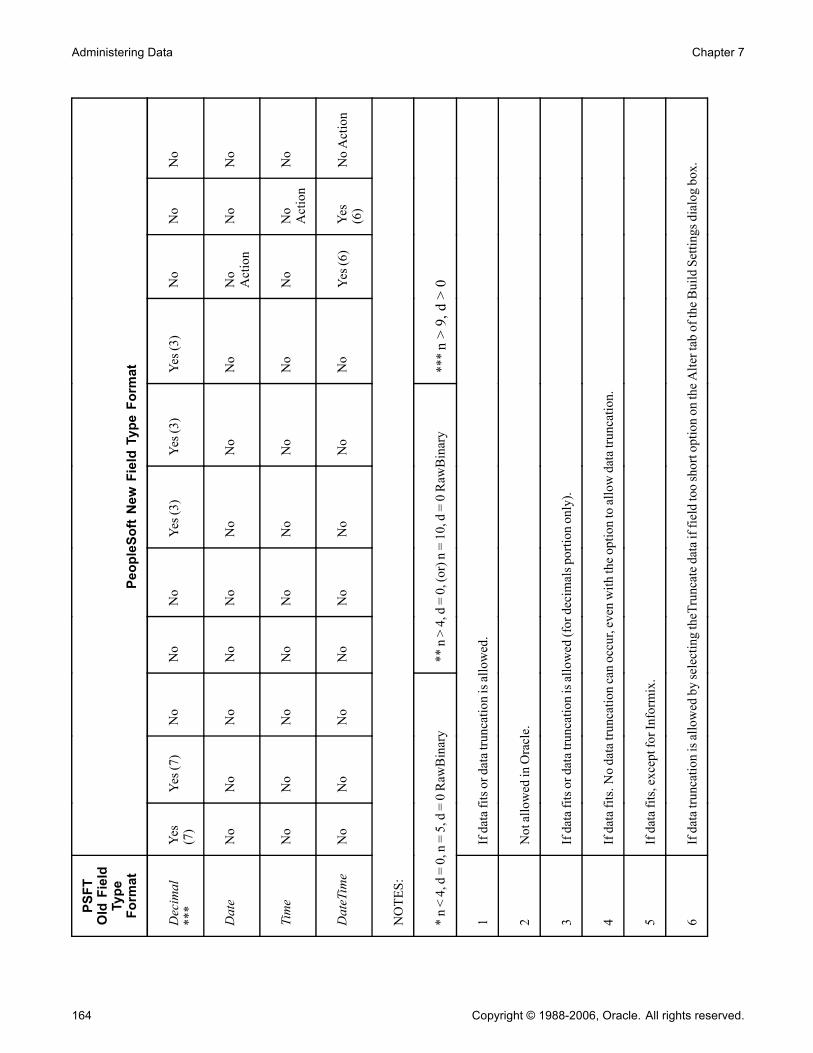
Administering Data Chapter 7
PSFT
OldField
Type
Format
PeopleSoftNew
FieldType
Format
Decimal
***
Yes
(7)
Yes(7)
No
No
No
Yes(3)
Yes(3)
Yes(3)
No
No
No
Date
No
No
No
No
No
No
No
No
NoAction
No
No
Time
No
No
No
No
No
No
No
No
No
NoAction
No
DateTime
No
No
No
No
No
No
No
No
Yes(6)
Yes
(6)
NoAction
NOTES:
*n<4,d=0,n=5,d=0RawBinary
**n>4,d=0,(or)n=10,d=0RawBinary
***n>9,d>0
1Ifdatafitsordatatruncationisallowed.
2NotallowedinOracle.
3Ifdatafitsordatatruncationisallowed(fordecimalsportiononly).
4Ifdatafits.Nodatatruncationcanoccur,evenwiththeoptiontoallowdatatruncation.
5Ifdatafits,exceptforInformix.
6IfdatatruncationisallowedbyselectingtheTruncatedataiffieldtooshortoptionontheAltertaboftheBuildSettingsdialogbox.
164 Copyright © 1988-2006, Oracle. All rights reserved.

Chapter 7 Administering Data
PSFT
OldField
Type
Format
PeopleSoftNew
FieldType
Format
7Ifdatafits,exceptifdatahasdecimalvaluesorforInformix.
8IfimageorlongcharacterchangefromNulltoNotNullorNotNulltoNull,otherwise,noaction.
9AllowedonallplatformsexceptInformix(duetoanInformixlimitation).
Copyright © 1988-2006, Oracle. All rights reserved. 165
Administering Data Chapter 7
Alter Process TipsThe following lists information to keep in mind as you create and run the alter scripts:
• Temporary tables during alter:When you run the Alter process, the script might create a temporary table. Temporary tables are namedPSY%tablename%, and they are created in the altered table’s tablespace—the tablespace currently defined inthe record definition.
• Alter process on tables containing logs on Oracle:Oracle does not allow an INSERT or SELECT FROM command if the table contains a LONG VARCHARor LONG RAW. Therefore, PeopleSoft uses an Oracle PL/SQL script to do alters on tables in Oracle thatcontain any type of LONG data type.
• Alter process on Oracle on records with CHAR fields greater than 1333 bytes but less than 2000 bytes:For Oracle, records with CHAR fields of length greater than 1333 characters and less than 2000 characterswill appear in the alter SQL script as needing to be altered, even if nothing has changed. On Oracle Unicodedatabases, PeopleSoft triples the length of a field while creating a table with a VARCHAR2 column in thedatabase to store all three bytes of the Unicode character. On Oracle databases, VARCHAR2 can store up to4000 bytes which means there is a restriction to store only 1333 characters (with three bytes each).For example, if a LONG CHAR field is designed with a length of 1999 characters, PeopleSoft interpretsthe field as a VARCHAR2, and creates the column with a size of 1333 characters. The field length ofthat LONG CHAR field will be stored as 1999 in the PSRECFIELD table, but in the database it will becreated with a size of 1333. So, each time a record with a LONG CHAR field of 1999 (or any value >1333), the alter process detects the difference between the 1999 character length in PSRECFIELD and the1333 character length in the database and generates the alter script. In addition, PeopleSoft also creates aconstraint on the VARCHAR2.
• View dependencies:PeopleSoft Application Designer does not keep track of view dependencies. When the structure of a tablechanges, it is a good idea to re-create all views. Many database environments track this information, soyou might be able to determine view dependencies by issuing a query directly against the system catalog.However, if you are not the DBA, you might not have the authority to run such a query successfully.Also, renaming or dropping a table, view, or column might invalidate view text, dynamic view text, andpossibly other stored queries.This table shows what happens to views by database platform:
Database Platforms
What Happens tothe Dependent ViewsWhen a Table Gets
Dropped?
Do the InoperativeViews Become
Operative When theTable is Re-created? Comments
Microsoft SQL Server Become inoperative. Yes The dependency reportedby sp_depends is incorrectuntil you recreate the view.
Sybase Become inoperative. Yes The dependency reportedby sp_depends is incorrectuntil you recreate the view.
166 Copyright © 1988-2006, Oracle. All rights reserved.

Chapter 7 Administering Data
Database Platforms
What Happens tothe Dependent ViewsWhen a Table Gets
Dropped?
Do the InoperativeViews Become
Operative When theTable is Re-created? Comments
Oracle Become inoperative. Yes, but only after the firstuse of the dependent view.
The VIEW object that hadbecome invalid remainsinvalid until its first use.The Oracle catalog table forobjects marks the view asvalid again.
Informix Get dropped when the tablegets dropped.
Not applicable (NA). Views need to be createdbecause the system dropsthem along with the tabledrop.
DB2/UDB for Linux,UNIX, andWindows
Become inoperative. No Views need to be re-createdto make them operative.
DB2 UDB for OS/390 andz/OS
Get dropped when the tablegets dropped.
NA Views need to be re-createdbecause the system dropsthem along with the tabledrop.
• Alter script:After you invoke the Alter process, the system uses the default value that is defined in the record definitionto populate the column on the altered table. The alter script that is generated contains detailed comments (--)to assist you if you must modify the script manually.
When to Alter TablesThe following record definition changes affect synchronization with the application table and require analter process:
• Add or delete a field on the record.• Modify the length of a field.• Change the required status of a date, time, DateTime, or long field.• Rename a field.• Rename a record.
The Alter Table process is similar to the Create Table process, except that it does not drop existing applicationdata tables and the data that they contain.
Note. The Build process automatically alters records with more than 16 keys to support functional indexes.A warning message indicating this is included in the log file for Microsoft SQL Server and DB2/UDB forLinux, UNIX, and Windows. For Informix, the warning message reads: "The record %s has more than 16keys. Indexes will be re-created to support functional indexes."
Determining Tables to be Altered After a Field ChangeTo determine tables to be altered after a field change:
1. Create a new project.
Copyright © 1988-2006, Oracle. All rights reserved. 167

Administering Data Chapter 7
2. Open the altered field.3. Select Edit, Find Definition References.The referenced definitions appear in the output window.
4. Select all of the rows that appear in the output window.5. Right-click the selected rows, and select Insert Into Project from the pop-up menu.
Altering a TableTo alter a table:
1. Open the project for which you must perform an alter.
2. From the Build menu, select the appropriate scope of your build.
The Build dialog box appears.
3. Select Alter Tables in the Build Options group box.
Selecting the Alter Tables option automatically selects and disables the Create Indexes and Create Trigger(only if triggers are needed) option. In the Build Execute Options group box, only the Build script fileoption is enabled.
4. Click the Settings button in the Build dialog box to set user-defined defaults.
Select the appropriate alter, logging, and scripts settings.
Note. The alter process takes care of the indexes regardless of the Alter Table Options you select on theAlter tab of the Build Settings dialog box. In the case of "Alter by Table Rename," the indexes are droppedautomatically when the temp table is dropped. For the "Alter in Place" option, the index creation processgoes through the "Recreate index only if modified" option on the Create tab.
5. In the Build dialog box, click Build to run the Alter Tables process.The length of a build process depends on the number of definitions that require building. Watch theBuild Progress dialog box to monitor the Build process. When the process completes, check any errorslisted in the log file.
Specifying Alter OptionsAccess the Build Settings dialog box. Select the Alter tab.
168 Copyright © 1988-2006, Oracle. All rights reserved.
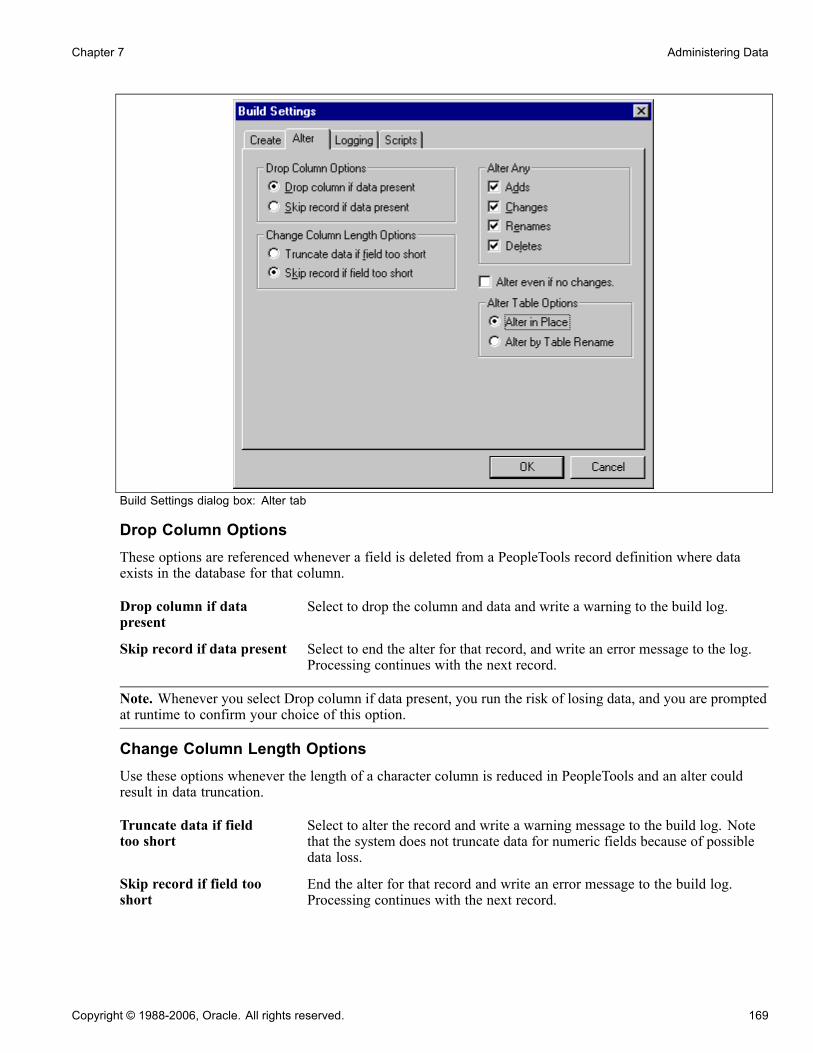
Chapter 7 Administering Data
Build Settings dialog box: Alter tab
Drop Column OptionsThese options are referenced whenever a field is deleted from a PeopleTools record definition where dataexists in the database for that column.
Drop column if datapresent
Select to drop the column and data and write a warning to the build log.
Skip record if data present Select to end the alter for that record, and write an error message to the log.Processing continues with the next record.
Note. Whenever you select Drop column if data present, you run the risk of losing data, and you are promptedat runtime to confirm your choice of this option.
Change Column Length OptionsUse these options whenever the length of a character column is reduced in PeopleTools and an alter couldresult in data truncation.
Truncate data if fieldtoo short
Select to alter the record and write a warning message to the build log. Notethat the system does not truncate data for numeric fields because of possibledata loss.
Skip record if field tooshort
End the alter for that record and write an error message to the build log.Processing continues with the next record.
Copyright © 1988-2006, Oracle. All rights reserved. 169

Administering Data Chapter 7
Note. Whenever you select Truncate data if field too short, you run the risk of losing data, and you areprompted at runtime to confirm your choice of this option. Also, numeric fields are not truncated to avoidany loss of data.
Alter AnyPeopleTools assumes that you want to perform alters for any modifications made to tables, so, by default, allof the check boxes in the Alter Any group box are selected. Alter Any allows for custom alter processingregarding adds, changes, renames, and deletes. For example, you have the flexibility to add, change, andrename fields, but not to delete any removed columns. When you complete any other custom externalconversion processes, you can then enable the delete processing to drop columns that are no longer defined.
Normally, you select all of these options, but during upgrades or operations requiring data conversion steps,you might select a subset of actions. For example:
• Perform alter with Adds and Changes selected.• Perform data conversion routines to populate the new and changed columns (perhaps from columns thatare ultimately to be dropped).
• Perform alter with Rename and Delete selected.
Alter even if no changesSelect this check box to force an alter, even if no changes are made to the tables. This check box is cleared bydefault. If selected, the Alter by Table Rename option in the Alter Table Options group box is automaticallyselected, and the Alter in Place option is disabled.
Alter Table OptionsWhen altering tables, the alter process takes care of the indexes regardless of the Alter Table Options youselect on the Alter tab of the Build Settings dialog box. In the case of Alter by Table Rename, the indexesare dropped automatically when the temp table is dropped. For the Alter in Place option, the index creationprocess goes through the Recreated index only if modified option on the Create tab.
• Alter in PlaceSelected by default. For database platforms in which Alter in Place is not supported, alter is automaticallydone by Alter by Table Rename (even if that option is not selected).Database platforms vary in the capabilities for Alter in Place table operations. The following table displaysthe limitations for each operation by platform:
170 Copyright © 1988-2006, Oracle. All rights reserved.

Chapter 7 Administering Data
DatabasePlatforms
Add Column Change Column(data type, size,precision, scale,and null/notnull propertychange)
Rename Table Delete Column
Microsoft SQLServer
Yes * Yes * Yes * Yes *
Oracle Yes * No Yes Yes *
DB2/UDB forOS/390 and z/OS
Yes * No No No
DB2/UDB forLinux, UNIX, andWindows
Yes * No No No
Sybase No No Yes No
Informix Yes Yes Yes Yes
* Certain restrictions might apply to this operation. Refer to the documentation delivered with your specificdatabase platform for more information.
• Alter by Table RenameSelect to create a temporary table (with changes made to the original table or its fields); the data from theoriginal table is imported into the temporary table. The original table is then dropped and the temporarytable is renamed to the original table.If a table is renamed from the old name to a new name, the indexes that were created on the old tableare moved to the new table, but the index names remain in the old table’s name. With Alter by TableRename selected, the indexes of the old table are dropped before being renamed to the new table name andthe indexes are re-created after the table is renamed to the new name. This way, the index is created inthe new table’s name.
Confirming Your Table AlterTo confirm your table alter:
1. Review the SQL script that was generated by the Alter process.Use your native SQL command processor to open the SQL script. The script is located where you specifiedon the Scripts tab of the Build Settings dialog box.
2. Run the script against your database.3. Use your query tool and SQL Select statements to confirm that the Alter Tables process has created anapplication table that corresponds to your record definition and has updated the system catalog tables.
Copyright © 1988-2006, Oracle. All rights reserved. 171

Administering Data Chapter 7
Creating TriggersA database trigger is a type of stored procedure that runs automatically when a user makes a specificdata-modification statement (INSERT, UPDATE, or DELETE) on a specified table. Within PeopleTools,triggers are created in tables related to synchronization for mobile applications and for optimization servers.Triggers are not created for all records; they are created only for records where specific properties have been set.
For example, in a mobile component record, set the required properties for that record so that triggers arecreated during the Build process. Using the Build dialog box, create the trigger by selecting the Create Triggercheck box in Build Options. Using the Build Execute options, you can either generate the SQL or run thebuild online. There are, however, usage and implementation restrictions.
See Enterprise PeopleTools 8.48 PeopleBook: PeopleSoft Mobile Agent, “Using Synchronizable ComponentInterfaces,” Understanding the Synchronization ID and Datetime Stamp.
See AlsoEnterprise PeopleTools 8.48 PeopleBook: PeopleSoft Optimization Framework, “Designing Analytic TypeDefinitions,” Creating and Building Optimization Records
Creating ViewsThis section provides an overview of online views and discusses how to:
• Create views.• Use joins in views.• Use cross-platform meta-SQL for dynamic views.
Understanding ViewsViews in PeopleSoft applications are comparable to views used in traditional RDBMS technology. A view, inessence, is a virtual table. It is created from the results of a query run against one or more tables.
When you create views to use online, you must keep the views synchronized with the database. Like SQLtables, you must have a record definition for online views because the system checks the record definitions foronline processing rules. You must build the view before you can use or reference it online.
If you use a view as the basis for a page, you select existing information to display on the page. Therefore,when you create the record definition for your view, you can clone an existing record definition, delete anyfields that are not used in the view, and proceed to define the view. Query views are processed the same way asview text, which is defined as part of the record.
The order in which PeopleTools creates views is based on the build sequence number that you set on theRecord Type tab while the record is open. The default build sequence number is 1. For the dependent views tobe created first, the build sequence number should be 0. This way, all of the 0 views are created first, then the1s, and finally the views that are greater than 1. Although the views are sorted in alphabetical order in theproject, they are created based on the build sequence number.
172 Copyright © 1988-2006, Oracle. All rights reserved.

Chapter 7 Administering Data
Creating ViewsIf you’re already familiar with creating record definitions and writing SQL queries, creating online viewsis quite similar.
To create online views:
1. Clone a record definition:a. Open an existing record definition.b. Select File, Save As.c. Specify the name of the view that you want to create.
2. Delete and add the appropriate fields.All columns that are selected in your view should have a corresponding field in the record definition.
3. Set the record type to SQL View:a. Select the Record Type tab for the record definition.b. Select SQL View in the Record Type group box.
4. Click the Click to open SQL Editor button.The order in which you list the columns in your SQL SELECT statement should match the order that youspecified in the record definition. A SQL statement can be given for each platform.
See Chapter 6, “Creating Record Definitions,” Creating SQL View and Dynamic View Select Statements,page 133.
5. Save the record definition.6. Select Build, Current Definition to create the view in the database.7. Select the Create Views check box under Build Options.8. Click Build.
Using Joins in ViewsIf you plan to use a join on a regular basis, you can save it as a SQL script, or you can create a view—a singlevirtual table—using the join as the logical representation of the data. After you create a view, the users neverneed to know that the data that they’re viewing is stored in multiple tables. To users, the relative complexity ofyour view is transparent. For example:
SELECT A.EMPLID,
A.NAME,
B.CONTACT_NAME,
B.RELATIONSHIP
FROM PS_PERSONAL_DATA A,
PS_EMERGENCY_CNTCT B
WHERE A.EMPLID = B.EMPLID;
Using Cross-Platform Meta-SQL for Dynamic ViewsPeopleTools includes functionality to produce meta-SQL constructs for dynamic views. This means thatdynamic SQL views that are created using PeopleSoft Application Designer can be used on any platform that issupported by PeopleSoft. The PeopleSoft PeopleTools PeopleBook: PeopleCode Developer’s Guide contains afull list of the meta-SQL that is supported in the PeopleSoft Internet Architecture.
Copyright © 1988-2006, Oracle. All rights reserved. 173
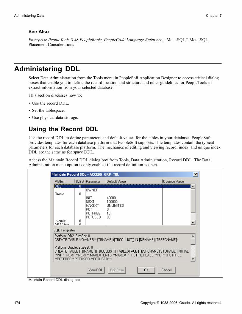
Administering Data Chapter 7
See AlsoEnterprise PeopleTools 8.48 PeopleBook: PeopleCode Language Reference, “Meta-SQL,” Meta-SQLPlacement Considerations
Administering DDLSelect Data Administration from the Tools menu in PeopleSoft Application Designer to access critical dialogboxes that enable you to define the record location and structure and other guidelines for PeopleTools toextract information from your selected database.
This section discusses how to:
• Use the record DDL.• Set the tablespace.• Use physical data storage.
Using the Record DDLUse the record DDL to define parameters and default values for the tables in your database. PeopleSoftprovides templates for each database platform that PeopleSoft supports. The templates contain the typicalparameters for each database platform. The mechanics of editing and viewing record, index, and unique indexDDL are the same as for space DDL.
Access the Maintain Record DDL dialog box from Tools, Data Administration, Record DDL. The DataAdministration menu option is only enabled if a record definition is open.
Maintain Record DDL dialog box
174 Copyright © 1988-2006, Oracle. All rights reserved.

Chapter 7 Administering Data
View DDL Select a Platform row in the Maintain Record DDL dialog box to enablethe View DDL button. This button opens the DDL Statements dialog boxwhich displays the CREATE TABLE DDL for the current record on eachof the database platforms.
Edit Parm (Parameter) Select a Parameter row in the Maintain Record DDL dialog box to enable theEdit Parm button. This button opens the Edit Override Parm Value dialog boxwhere you can enter a new value to override the Default Value listed in thetable. The new value is stored in the PSRECDDLPARM override table.
Setting the TablespaceThe Change Space dialog box is an editing tool with which you can select the space name and view therecords attributed to the named space in the database.
Access this dialog by selecting Tools, Data Administration, Set Tablespace. This dialog box also appearsautomatically when you attempt to save a new record definition. For each new record definition that is createdin PeopleSoft Application Designer, a tablespace name must be allocated. For the Change Space dialog box toappear upon saving a new record definition, the Platform Compatibility Mode check box under PeopleTools,Utilities, PeopleTools Options must be selected.
Change Space dialog box
Record Name Displays the name of the current record definition. This field is display-only.
Platform Select from the available database platforms to which you can assign thedesignated space name.
Space Name.DB Name(tablespace name.databasename)
Displays the available space name that is assigned to the current record.This field is display-only.
Copyright © 1988-2006, Oracle. All rights reserved. 175
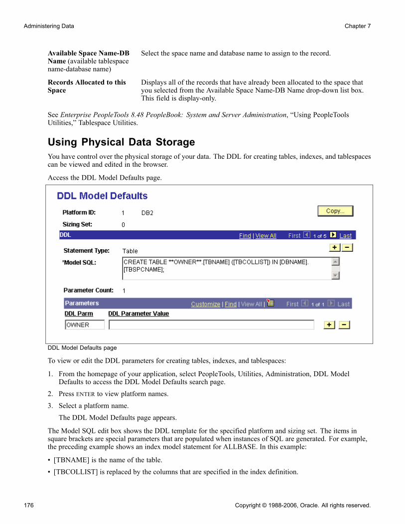
Administering Data Chapter 7
Available Space Name-DBName (available tablespacename-database name)
Select the space name and database name to assign to the record.
Records Allocated to thisSpace
Displays all of the records that have already been allocated to the space thatyou selected from the Available Space Name-DB Name drop-down list box.This field is display-only.
See Enterprise PeopleTools 8.48 PeopleBook: System and Server Administration, “Using PeopleToolsUtilities,” Tablespace Utilities.
Using Physical Data StorageYou have control over the physical storage of your data. The DDL for creating tables, indexes, and tablespacescan be viewed and edited in the browser.
Access the DDL Model Defaults page.
DDL Model Defaults page
To view or edit the DDL parameters for creating tables, indexes, and tablespaces:
1. From the homepage of your application, select PeopleTools, Utilities, Administration, DDL ModelDefaults to access the DDL Model Defaults search page.
2. Press ENTER to view platform names.3. Select a platform name.The DDL Model Defaults page appears.
The Model SQL edit box shows the DDL template for the specified platform and sizing set. The items insquare brackets are special parameters that are populated when instances of SQL are generated. For example,the preceding example shows an index model statement for ALLBASE. In this example:
• [TBNAME] is the name of the table.• [TBCOLLIST] is replaced by the columns that are specified in the index definition.
176 Copyright © 1988-2006, Oracle. All rights reserved.
Chapter 7 Administering Data
The model statements also contain parameter names enclosed in pairs of asterisks. A parameter nameis replaced by a value when instances of the SQL are generated. In the preceding example, there is oneparameter, **FILESET**. When DDL is generated using this model, the FILESET parameter is replaced byFILE, unless it is overridden for the specific record or tablespace. The other text in the model statement iscopied to the generated SQL.
See AlsoEnterprise PeopleTools 8.48 PeopleBook: System and Server Administration, “Using PeopleTools Utilities,”Using Administration Utilities
Copyright © 1988-2006, Oracle. All rights reserved. 177

Administering Data Chapter 7
178 Copyright © 1988-2006, Oracle. All rights reserved.
CHAPTER 8
Designing Pages for Optimal Performanceand Accessibility
Developing pages for internet applications requires certain design techniques to optimize performance and offer thegreatest accessibility for users. This section discusses how to:
• Improve online performance.• Design accessible pages.
Improving Online PerformanceTo improve online performance of internet applications, you must optimize the transmissions to the server.Optimizing transmissions improves overall processing speed and reduces the user’s data entry time.
Transactions that are designed using deferred mode reduce traffic to the application server but do not operateinteractively.
This section provides an overview of processing modes and discusses how to:
• Refresh a page.• Trigger server processing.• Use PeopleCode in deferred mode.• Use page controls in deferred mode.• Use error and warning messages.
Understanding Processing ModesPeopleSoft applications can run in two different processing modes: interactive and deferred.
Interactive ModeIn interactive mode (formerly called standard), when the user exits a field that has a field-level event (forexample, FieldChange, FieldEdit, RowInsert PeopleCode, prompt validation, related display, and so on):
1. A transmission to the application server is performed to run that field-level event.2. The page is displayed again.
Copyright © 1988-2006, Oracle. All rights reserved. 179
Designing Pages for Optimal Performance and Accessibility Chapter 8
Deferred ModeDeferred mode enables you to defer many of the conditions that need server processing until running them onthe application server is required or requested. For example, when a user exits a field that has a field-levelevent (like FieldChange or FieldEdit PeopleCode, prompt validation, related display, and so on), that event isnot run until the next transmission to the application server. When the next transmission to the server occurs,PeopleTools determines which fields have changed since the last transmission. Logic on the application serverruns the appropriate system edits and PeopleCode events (in field layout order).
You can select deferred mode processing at the field, page, and component levels. For a field in the componentto run in deferred mode, you must select deferred mode at each of those levels. Deferred processing is thedefault mode at the field, page, and component levels.
Refreshing a PageClick the Refresh button on a page to force processing on the application server to determine which fields havechanged since the last transmission and to run processing logic that is associated with those changes.
Users can also refresh by pressing the ALT-0 hot key, which keeps the cursor in the same field when the page isdisplayed again. You can refresh at any time during data entry to enable an expert user to:
• Update related display field values for the data that is already entered.
• Recalculate totals and balances.
• Provide defaults that are based on prior data that was entered on the page.
• Validate the data that has been entered on the page so far.
• Invoke any hide, unhide, gray, or ungray code that is associated with specific fields.
Note. The refresh button does not refresh the page from the database. It does cause a server trip so that anydeferred PeopleCode changes can be processed. If there are no deferred changes or the deferred changes do notcause any errors or other changes on the page, clicking Refresh has no effect. It may appear to the user thatnothing happened. Fields on derived work records are not updated if the user clicks the Refresh button.
Triggering Server ProcessingThe following table shows the events that cause the PeopleTools runtime environment to run logic on theapplication server when operating in deferred or interactive processing mode:
Event Deferred Processing Interactive Processing
Entering data in fields withPeopleCode (for example, FieldEditand FieldChange) associated withthem.
X
Entering data in fields that haveprompt table edits.
X
Entering data in fields that haverelated displays.
X
180 Copyright © 1988-2006, Oracle. All rights reserved.

Chapter 8 Designing Pages for Optimal Performance and Accessibility
Event Deferred Processing Interactive Processing
Inserting a row or series of rows in agrid or scroll area.
X X
Deleting a row from a grid or scrollarea.
X X
Using the grid or scroll area controlsto move forward or back.
X X
Selecting another page tab. X X
Selecting another grid tab. X X
Expanding or collapsing acollapsible section.
X X
Clicking any button or icon on thepage.
X X
Clicking any link on the page. X X
Clicking the Refresh toolbar button. X X
Using the Refresh hot key. X X
Using PeopleCode in Deferred ModeWhen designing transactions to run in deferred mode, note the following:
• Code field edits in FieldEdit PeopleCode; it is not necessary to move field edits to SaveEdit PeopleCode.• Code field change logic in FieldChange PeopleCode.• Set all fields, including those that have FieldEdit or FieldChange PeopleCode, to deferred processing.• Do not use gray and hide fields on the same page to achieve a form of progressive disclosure on the page.Specifically, do not include hide or unhide and gray or ungray FieldEdit and FieldChange PeopleCode fordefinitions on the same page, unless it is triggered by a separate push button. Instead, use either pageActivate PeopleCode or FieldChange PeopleCode for definitions that are on another page in the component.The page display should be static as the user enters values and moves between fields on the page.PeopleSoft recommends that you hide or unhide definitions, or set them to display-only in pageActivate PeopleCode before the page is initially displayed based on setup data, configuration options, orpersonalization settings. Set fields to display-only in PeopleCode by setting the DisplayOnly property inthe Field class to true.
Copyright © 1988-2006, Oracle. All rights reserved. 181
Designing Pages for Optimal Performance and Accessibility Chapter 8
• Show all fields as a static form, and perform cross-validation edits to prevent invalid data combinations frombeing written to the database.
• Cross-validation edits should always assume that the controlling field (for example, a radio button, checkbox, drop down list box, and so on) is correct when editing for invalid combinations.Use SaveEdit to code cross-validation edits. If the transaction requires that the edits be performed beforethe user can select another folder tab, code the edits in a function that is called from the page ActivatePeopleCode for every other visible page in the component. If the transaction is a sequential step-by-stepprocess, add the cross-validation edits to the Next and Previous buttons that navigate the user through theprocess. Code cross-validation edits at the record level if the cross-validation edits apply to all componentsand at the component level if they apply to only one component.
Publishing Messages in PeopleCodeUse the SavePostChange event, either from record-field or component PeopleCode, to publish messagesonline. PeopleTools has special logic in SavePostChange PeopleCode that defers publishing until just beforethe commit for the transaction. This minimizes the time that the system locks single-threaded PeopleSoftIntegration Broker tables.
See AlsoEnterprise PeopleTools 8.48 PeopleBook: PeopleCode Developer’s Guide, “PeopleCode and the ComponentProcessor,” Deferred Processing Mode
Using Page Controls in Deferred ModeConsider the following when designing transactions to run in deferred mode.
Edit TablesFields that have edit tables should be set to deferred. The user can click the Refresh button for immediatevalidation of the field; otherwise, the prompt validation is deferred until the next required transmission tothe application server.
Prompt TablesUse deferred processing on prompt table edits that use %EditTable to set the prompt keys based on thevalues of other fields on the page. Deferred processing still results in the appropriate behavior being run. Forexample, if the user clicks the prompt icon, the system:
1. Determines which fields have changed since the prior server transmission.2. Runs the appropriate PeopleCode events.3. Applies the values from the page to the buffer.This results in setting the correct values before resolving the %EditTable function, provided that anycontrolling fields come before the prompt table edit based on the page layout order.
4. Runs the prompt table edit lookup logic for the corresponding field.
Drop-Down List BoxesDo not use drop-down list boxes when the high-order key values are set on the same page. If you do, it requiresthe server to transmit the correct drop-down list box values based on the high-order key values. Therefore, setthe high-order keys on another page, if possible, or use a prompt lookup instead.
182 Copyright © 1988-2006, Oracle. All rights reserved.
Chapter 8 Designing Pages for Optimal Performance and Accessibility
For pages that have an effective-dated scroll area and a drop-down list box based on the PSXLATITEMtranslate table, the drop-down list box is not refreshed when the effective date is changed on the page.However, the drop-down list box does accurately reflect the new effective date the next time that the pageis displayed. Evaluate whether this is a problem for the transaction, based on whether customers typicallyenter effective-dated XLAT rows for the field and on how often changes to the XLAT values are made. Ifthis is an issue, either replace the drop-down list box with an edit box and a prompt, or use the refresh iconafter the effective date field.
Drop-down list boxes are a good design choice because they present users with a small number of selectionsfrom which they must select one. They are typically more appropriate than prompts for transactions that aretargeted at casual, untrained users. Prompts are more appropriate when a power user is entering the transactionfrom a paper form or document that contains the necessary codes.
Check Boxes and Radio ButtonsRemove any FieldChange PeopleCode associated with check boxes in a grid that are mutually exclusive(meaning only one row can be checked). Instead, implement cross-validation edits in SavePreChangePeopleCode. When you design cross-validation edits between a radio button or check box and any associatededit box fields, assume that the controlling field (in this case, the radio button or check box) is correct.
Related DisplaysWhen you include related displays on your pages, make sure that they are set to deferred mode and that thestandard Refresh button is enabled. Then, users can press the Refresh hot key to display related displayswhen they want to see them. Self-service transactions should not display the code and corresponding relateddisplay, but rather should use descriptive prompts.
Adding Multiple RowsThis feature enables the user to specify the number of blank rows to be added by clicking the InsertRow icon.
The number of blank lines that are specified by the user is included on the page when it is displayed again, soapplication server processing is no longer required for each row that is added.
Do not use this for effective-dated grids or scroll areas.
Multirow inserts might not apply if the entire row is populated using PeopleCode, especially if the data iscopied from prior rows. If a multirow insert does apply, the default value of the ChangeOnInit property can beused. (The default value is True, which means that any PeopleCode updates done in the RowInit or RowInsertevents set the IsChanged and IsNew properties to True.)
Once a transaction is saved, empty rows are discarded before the page is displayed again to the user. Anempty row means that the user did not access the data and that PeopleCode or record defaults might havebeen used to initialize the row for the initial display.
PeopleCode Save processing (that is, SaveEdit and SavePreChange PeopleCode) runs for all rows that are inthe buffer (including the empty ones). Therefore, SaveEdit and SavePreChange PeopleCode should be codedso that it runs only if the field contains data or if the row properties IsNew and IsChanged are both true.
An alternative method is adding PeopleCode in the first save program in the component to explicitly delete anyrow based on the IsNew and IsChanged properties. If you choose this method, then rows should be deletedfrom the bottom of the data buffer to the top (last row first).
To implement multirow insert:
1. Ensure that deferred processing is set.
Copyright © 1988-2006, Oracle. All rights reserved. 183
Designing Pages for Optimal Performance and Accessibility Chapter 8
Open PeopleSoft Application Designer and ensure that deferred mode is set for the component, all pages inthe component, and all fields on each page.
2. Access the Page Properties dialog box of the appropriate control.3. Enable multirow insert.For each grid or scroll area where appropriate, select the Allow Multi-row Insert check box under theUse tab in the grid or scroll area property sheet.
4. Add ChangeOnInit PeopleCode.Setting the ChangeOnInit property for a rowset to FALSE enables PeopleCode to modify data in the rowset during RowInit and RowInsert events without flagging the rows as changed. This ensures that onlychanges entered by the user cause the affected row to be saved.
Note. Each rowset that is referenced by a grid or scroll area with multirow insert enabled should have theChangeOnInit property for the rowset to FALSE. This includes child, or lower level, rowsets. In addition,this property must be set before any RowInsert or RowInit PeopleCode for the affected row.
Using Error and Warning MessagesWhen components, pages, and fields are set to deferred mode, FieldEdit PeopleCode errors and warnings arenot displayed when the user exits the field, but rather after the next application server transmission. Therefore,users might not receive an error message until they enter all of the data and click the Save button.
For FieldEdit error messages running in deferred mode, the system changes the field to red and positions thecursor to the field in error when it displays the message. This allows the user to associate the error messagewith a specific field. However, for warning messages, the system does not display fields, nor reposition thecursor. Consequently, create warning messages that clearly describe to which fields they apply. For example,if a page contained a "Date out of range" warning, it would be confusing to users if there were multipledate fields on the page.
Designing Accessible PagesYou want to design an application page that is useful to the user and supports assistive technologies.
This section provides an overview of accessibility issues and discusses how to:
• Use labels.• Use color to convey meaning.
• Verify titles for grids and scroll areas.
• Add unique labels for buttons and links.
• Deactivate adornment images.
• Maintain logical tab order.
• Use deferred processing.
• Use foreground and background colors.
• Use instructional text.
184 Copyright © 1988-2006, Oracle. All rights reserved.

Chapter 8 Designing Pages for Optimal Performance and Accessibility
Understanding Accessibility IssuesPeopleSoft is committed to designing transactions that are accessible to all users. When you create or modifyPeopleSoft Internet Architecture pages for your system, consider the needs of all users who might access thesepages. Make sure that users with disabilities can navigate quickly and cleanly through your transactions whenusing screen reader software. Before you design your page, use the following checklist to create a properlydesigned application page that also addresses important usability issues:
• Do all functional images have labels?Do these labels effectively communicate the purpose of the image?
• Do all data entry fields have labels near the entry field?• Do all grid columns have labels (excluding columns with buttons or links)?• Do all grids and scroll areas have titles?• Do all buttons and links have unique labels?• Do adornment images have labels deactivated?• Is the tab order correct?• Is deferred processing activated?If not, is field processing kept to a minimum?
• Do foreground and background colors provide sufficient contrast?• Do your self-service pages have instructional text?• Did you remove abbreviations used in labels and column headers?• If your page contains HTML not generated by PeopleTools (such as code in an HTML area) or an applet, firstcheck that the code follows the Section 508 accessibility standards. The applicable standards are in SubpartB, Technical Standards, Section 1194.22Web-based Intranet and Internet Information and Applications.
See http://www.access-board.gov/sec508/508standards.htm
Some of these features are set in design time and can be activated or deactivated by the system administratorand the end user. The system administrator controls the availability of functions to the user from PeopleToolsSecurity. The end user can then activate the options on the My Personalizations page.
See AlsoEnterprise PeopleTools 8.48 PeopleBook: Security Administration, “Managing PeopleSoft Personalizations,”Working with the My Personalizations Interface
Enterprise PeopleTools 8.48 PeopleBook: Using PeopleSoft Applications, “Working With Browser-BasedApplications,” Using Accessibility Features
Using LabelsConsider the use of labels for functional images, data-entry fields, and grid columns in your application page.
Copyright © 1988-2006, Oracle. All rights reserved. 185

Designing Pages for Optimal Performance and Accessibility Chapter 8
Labels for Functional ImagesAll functional images need a good label. Functional images are image buttons, image links, and static anddynamic images that convey meaningful information. Images that do not require labels are spacer (or invisible)Graphics Interchange Format (GIF) files and adornments (images that do not serve a functional purposeother than to provide visual interest). A good label is vital for blind users to understand the meaning of animage. Labels also clarify the meaning of images for sighted users, because the labels appear as mouse-overtext on some browsers.
Assign labels to images using alternate text, or the ALT HTML tag. You can set alternate text for staticimages, dynamic images, push buttons and link images, and control buttons in scroll areas and grids. Assignalternate text on the Label tab of the Properties dialog box for the control that you specify. You can use theMessage Catalog, custom label text, or the RFT long or RFT short label, if one has already been designated inthe record field. There are alternative text entries in the Message Catalog for the following page elements:folder tabs, scroll left and right buttons, hide and show grid tabs, prompt buttons, expand and collapse buttonsfor grids, group boxes, and scroll areas.
Note. Any alternate text that you select is visible to all users as mouse-over text on some browsers regardlessof whether the system administrator makes the accessibility features available to users in PeopleTools Security.
To specify a label for an image push button or link associated with a record field:
1. Open the Page Field Properties dialog box for the control.2. Select Image as the type.3. Determine the RFT names:
a. If the RFT name is descriptive, set the label type to that RFT name.b. If the RFT name is not adequate, edit the RFT name or write a message using the Message Catalog.
Note. Image buttons and links not associated with record fields should use messages exclusively.
The steps to specify a label for other types of images are the same as for image buttons and links, with thefollowing differences:
• For dynamic images, you can choose to use RFT names or messages.
• For static images, you can only use messages or static text.
PeopleSoft recommends using the Message Catalog.
Labels for Data-Entry FieldsAll edit boxes, check boxes, radio buttons, and long edit boxes should have labels near the entry field. Thelabel should be the actual label for the field or the label from a hidden field, and so on.
Do not use a second independent field as the label for an edit field. This causes the field that is serving as alabel and the edit field to be disassociated by a screen reader, and it is confusing to blind users. It also results ina page that contains a field without a label and a label without a field.
Labels for Grid ColumnsAll grid columns need a label. The only grid columns that do not have labels include those that containbuttons or links.
186 Copyright © 1988-2006, Oracle. All rights reserved.

Chapter 8 Designing Pages for Optimal Performance and Accessibility
Using Color to Convey MeaningDo not use color as your only way to convey information. Include a redundant clue so that users who are blindor color-blind are aware that there is something special or different about a field or process. A common misuseof the color red is to change the background or text color to indicate an error. Another common mistake is touse an icon that changes color based on status but is otherwise the same. Color-blind users cannot distinguishbetween certain colors, nor can screen readers. In addition, if a user prints a page on a black and white printer,color-dependent items on the page become indistinguishable.
Use the approved set of icons in the table and see the following example on how to show status. All icons areGIFs or JPEGs.
PS_STATUS_OK_ICN: OK, normal, good
PS_STATUS_CAUTION_ICN: Warning, caution, at risk
PS_STATUS_ERROR_ICN: Error, critical
PS_STATUS_CLOSED_ICN: Completed
PS_STATUS_CANCELLED_ICN: Cancelled.
PS_STATUS_TREND_STABLE_ICN: Trend unchanged.
PS_STATUS_REQUIRED_ICN: Required.
Use a text field that describes the status. For example:
Status: Error
Use icons of different shape and color to represent each status. The icons should also have descriptivemouse-over text so that screen readers for blind users can interpret the meaning of the icons.
Using icons of different shapes and colors to denote status
Verifying Titles for Grids and Scroll AreasAll grids and scroll areas need to have meaningful titles. Sometimes titles are not used due to redundancybecause the label repeats the name of the page. However, while the grid may be visually close in proximityto a page title, it may not be close when read aloud by a screen reader. This may cause a loss of associationbetween the page and the grid, and the contents of the grid may become ambiguous.
Copyright © 1988-2006, Oracle. All rights reserved. 187
Designing Pages for Optimal Performance and Accessibility Chapter 8
Adding Unique Labels for Push Buttons and LinksButtons and links need unique names on a page. While you might visually associate a link with an area, theassociation might not be apparent to a screen reader. Also, screen readers have the ability to list all links on thepage. If there are two links with the same label, no distinction can be made to the user.
Deactivating Adornment ImagesAdornment images serve no functional purpose other than to provide visual interest. If the images have noinformation to convey to users and do not serve as navigation, then they should not have a label. Images usedas spacers, such as invisible GIFs, should not have labels.
To deactivate the label for an image:
1. Access the Image Properties dialog box.2. Select the Label tab.3. Set Label Text Type to Static Text.4. Delete any characters from the Text field, if it is present.It is not necessary to enter a space. Leave the Text field blank.
Maintaining Logical Tab OrderMaintaining a logical tab order on your page is critical because blind users cannot see the groupings or fieldproximity. Tab order is also important for sighted users because it can be confusing if the cursor moves tofields in an order different from how they appear on the screen.
Using Deferred ProcessingEvery time there is a trip to the server, your current page is refreshed. This "refresh" can make the screenreader lose focus of the field that the user was on, and it will start reading the page from the beginning.This includes navigation links and all other items on the page. It is difficult for users using a screen readerto find their place as well. Using deferred processing enables you to determine when the transmission tothe server needs to be made.
Using Foreground and Background ColorsText and background colors must have sufficient contrast to be viewed by someone with low vision orcolor-blindness. The PeopleSoft standard corporate style sheet is designed with this in mind. You mightconsider using the provided style sheets instead of custom ones.
Using Instructional TextInstructional text provides a brief overview of the page and a summary of the page contents for blind users. Byproviding instructional text, you save users from having to hear the contents of an entire page read aloud by thescreen reader. All self-service pages should contain at least a minimum of one or two lines of instructional text.
When writing instructions, labels, or any other text for transaction pages, follow these general guidelines:
• Know your audience and write to its level of expertise.• Do not make assumptions based on your expertise.• Avoid highly specialized technical slang that is unique to an occupational group.
188 Copyright © 1988-2006, Oracle. All rights reserved.

Chapter 8 Designing Pages for Optimal Performance and Accessibility
• Understand the task that you are describing.• Write clearly and concisely.• Use the fewest words required for clarity.• Use short sentences; avoid paragraphs.• Choose precise, imperative verbs.For example, use "Complete all fields" instead of "Please fill out all the fields below."
• Do not construct sentences that merge variable information into a sentence, as these sentences are difficultto translate.Use "OK to delete John Smith?" instead of "OK to delete dependent John Smith?"
• Correctly reference graphical user interface (GUI) elements.- You click buttons, you do not click on a button.- You select options, check boxes, and items in list boxes.You do not choose them.
- You press keyboard keys.- You clear options and check boxes (not uncheck, unmark, deselect, or other such variation).You can cancel a selection as well.
• You delete items (not remove them).• Use written English, not verbal English.(The English that you speak is not necessarily the English that you write.)
• Avoid contractions:
Poor Better
Won’t Will not
Didn’t Did not
Shouldn’t Should not
Can’t Cannot
• Use short, simple, nonthreatening words:
Poor Better
Abort Cancel, Stop
Execute Complete, Done
Implement Do, Use, Put Into
Copyright © 1988-2006, Oracle. All rights reserved. 189
Designing Pages for Optimal Performance and Accessibility Chapter 8
Poor Better
Invalid Not Correct, Not Good, Not Valid
Terminate End, Exit
• Avoid hyphenation.• Eliminate unnecessary words:
Poor Better
in order to to
so that so
in regards to regarding
Text for LabelsWhen writing labels, use the following guidelines:
• Write short, concise, yet descriptive labels.• Do not capitalize all letters in the words included in your label; use sentence case.• Use abbreviations only when there is limited space.• Follow field labels with a colon (:).• Do not use repetitive words.Use "Copy the overall definition for the following: Rules, Rates, Offerings" instead of "Copy the overalldefinition for the following: Rules definition, Rates definition, and Offerings definition."
Note. When using ampersands (&) in field labels (and hyperlinks) consider that PeopleSoft determines if afield has an access key based on whether or not the field label contains an ampersand (&). If the field labelcontains any ampersands, the last ampersand in the label along with the text following the last ampersand isused to create the text for the HTML and the system removes the last ampersand.
If the label contains a single ampersand (&), and the following character is not a blank space or anotherampersand, the character following the ampersand will be used as an access key. Use a double ampersand(&&) so that a single ’&’ appears in the label as well as enabling the character immediately following thesecond ampersand as the access key.
For example, ’&TEST’ appears on the page as ’TEST’ with the ’T’ activated as an access key. ’&&TESTappears on the page as ’&TEST’ with the ’T’ activated as an access key.
Text for TitlesWhen writing text for titles, use the following guidelines:
• Write titles that are short and descriptive.
190 Copyright © 1988-2006, Oracle. All rights reserved.
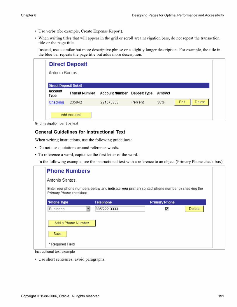
Chapter 8 Designing Pages for Optimal Performance and Accessibility
• Use verbs (for example, Create Expense Report).• When writing titles that will appear in the grid or scroll area navigation bars, do not repeat the transactiontitle or the page title.Instead, use a similar but more descriptive phrase or a slightly longer description. For example, the title inthe blue bar repeats the page title but adds more description:
Grid navigation bar title text
General Guidelines for Instructional TextWhen writing instructions, use the following guidelines:
• Do not use quotations around reference words.
• To reference a word, capitalize the first letter of the word.
In the following example, see the instructional text with a reference to an object (Primary Phone check box):
Instructional text example
• Use short sentences; avoid paragraphs.
Copyright © 1988-2006, Oracle. All rights reserved. 191

Designing Pages for Optimal Performance and Accessibility Chapter 8
Use "The listed competencies are based on your job. Complete the information where applicable. To enteradditional competencies, click Add. When completed, click Save" instead of "The following competencieslisted have been populated based on your job. Please complete the information below (where applicable) foryour perceived proficiency, your interest in developing this competency further, year acquired, year last used,and years of experience. If you need to add additional competencies, please click the Add button below."
• Use active voice.Use "Enter the part numbers" instead of "The part numbers should be entered."
Page Instructional TextPage instructional text provides users with instructions on how to complete a task on the page. Use thistext when pages have unique requirements or are particularly complex. When writing page instructionaltext, follow these guidelines:
• Place instructional text after level 0 identifying data.• Set the style of the instructional text to PAPAGEINSTRUCTIONS.• Derive instructional text from the Message Catalog.Use a unique message set for each product.
• Use Static Text to provide instructional text for a page.• When you need to create a dynamic phrase, embed bind variables in a message catalog entry.
Additional Instructional TextAdditional instructional text is used within a page and it helps users understand a specific section or field onthe page. Additional text can also be used as a footnote at the bottom of a section or page. Use this text when apage or sections of the page have unique requirements or are particularly complex.
192 Copyright © 1988-2006, Oracle. All rights reserved.
CHAPTER 9
Using Page Controls
This chapter provides an overview of page controls and discusses how to use:
• Charts.• Frames.• Group boxes.• Horizontal rules.• Images.• Static text.• Check boxes.• Drop-down list boxes.• Edit boxes and long edit boxes.• Radio buttons.• Subpages.• Grids.• HTML areas.• Push buttons or links.• Scroll areas and bars.• Secondary pages.
Understanding Page ControlsThere are three categories of controls that you use in page design and development. You determine which typesof controls that you want to add to your page definition by considering how you want to organize informationon a page as well as how your users will enter data.
This section discusses:
• Aesthetic controls.• Data entry controls.• Function and data processing controls.
Copyright © 1988-2006, Oracle. All rights reserved. 193

Using Page Controls Chapter 9
Aesthetic ControlsUse aesthetic controls to help organize, display, or emphasize information on the page. In most cases, aestheticcontrols are not associated with a particular record field that is defined in a record definition and maintainedin the database. With the exception of the image control, these controls never update data in the database.Aesthetic controls include:
Chart Draws a frame that serves as a placeholder for a chart that you construct usingthe GetChart field type in PeopleCode. Using the chart control, you drawa box in which the chart appears to the user at runtime. Associate the chartcontrol with a record field in a record definition.
Frame Draws a display-only box of variable size to visually group a set of controlson a page. You can drag a frame around almost any control. You can isolatecontrols, such as HTML areas, from other controls on the page and then hidethe frame. Frames generate HTML tables for viewing in the browser.
Group Box Draws a display-only box of variable size with a text label to visually groupand identify related controls, such as radio buttons. Like a frame, you canresize a group box to any length or width. However, with a group box youcan assign a visible label. Like frames, group boxes generate HTML tablesfor viewing in the browser.
Horizontal Rule Draws a horizontal line to separate parts of a page. Use the horizontal rulecontrol as a visual break between controls.
Image Draws a frame that you can associate with a variable image from a record fieldin the database. The record field stores a graphic, such as a scanned image ofan employee or a picture of an asset, in the format that you defined in therecord definition. Because an image can change at runtime and is associatedwith a record and field definition, it is considered a data entry control andan aesthetic control.The field that you associate with your image can be either a standard Imagetype field or an ImageReference type field, where images might be associatedwith it depending on user input. The ImageReference field type is a pointer toan image definition, which enables you to display images dynamically. Anexample of this is referencing a red, yellow, or green light image definition ona page, depending on the context when the page runs.
See Chapter 4, “Creating Field Definitions,” Specifying Image FieldAttributes, page 67.
See Chapter 4, “Creating Field Definitions,” Specifying ImageReferenceField Attributes, page 67.
Static Image Draws a frame that you can associate with an image definition. It can helporganize or identify information that is displayed on a page. A static image isdifferent from an image because it does not change at runtime, and it is notassociated with a record field, but instead with a predefined image definition.For example, you might select a static image, such as the yellow Clear button,from the image catalog and place it on top of a push button control so that theuser knows to click that button to clear the contents of the page.
See Chapter 15, “Creating Image Definitions,” Using the Catalog of ImageDefinitions, page 378.
194 Copyright © 1988-2006, Oracle. All rights reserved.

Chapter 9 Using Page Controls
Static Text Adds a static text item—a display-only alphanumeric field with a maximumlength of 60 characters to describe a page, control, or group of controls.You might use text for a static note, an extension of a control label, andoccasionally a control label itself. Try to avoid using text items because theymake it more difficult to translate pages to other languages. Instead you canreference message catalog text to facilitate translation and other maintenanceissues. Other methods of displaying text on a page are display-only edit boxes,field labels, or display-only long edit boxes.
Data Entry ControlsUse data entry controls to offer different ways to enter and maintain information. These types of controls arealways associated with a record field that is defined in a record definition and maintained in the database.
Note. The PeopleSoft Application Designer allows you add up to 405 fields on a page. When you havereached this limit, typical system behavior includes being unable to select, move, or edit the page fields withan order number exceeding the 405–field limit. While this limit has no affect on the page during runtime, ithas the potential to disrupt productivity during design time. If you find a page nearing the 405-field limit,PeopleSoft recommends using subpages to decrease the number of fields on a single page.
See Chapter 9, “Using Page Controls,” Using Subpages, page 208.
Check Box Adds a small square box that operates as a toggle switch—on and off—fordata controls that can have one of two values (yes or no, or 1 or 0).During data entry, when the page is saved, the enabled or disabled value(whichever represents the current state of the check box) is written to thedatabase. If values are specified in the page definition, the fields are left blankin the database, but you can still select or clear the check box on the page.You won’t know that the database fields are blank until you run a query orreport on the field.
Drop-Down List Box Adds a drop-down list box from which you select a single value from a list ofvalid values. Use drop-down list boxes to enable data selection from a list ofthree or more possible choices. In its closed state, the control displays thecurrent value for the control. The user opens the list to change the value.Drop-down list boxes are a good design choice when presenting userswith a small number of selections from which they must select one value.However, when designing for grids and scroll areas, prompts give you betterperformance.
Edit Box Adds an edit box, which is used for data entry. Edit boxes are also used fordisplaying fields and translatable text. Use an edit box for text data entry—forexample, a record field that is defined as character, number, signed number, ordate. Also use edit boxes for displaying fields and translatable text.
Long Edit Box Adds a long edit box, which is a variable-length, alphanumeric control that isused for entering long, textual items, such as comments. The length of thecontrol is determined by its contents, rather than the physical size of the boxon the page.Use long edit boxes to display long, translatable text. Each long edit box has abuilt-in scroll bar to enable users to enter and display more data than can be
Copyright © 1988-2006, Oracle. All rights reserved. 195

Using Page Controls Chapter 9
shown at one time on the page. The scroll bar on the long edit box is usedonly to scroll through the text in the long edit box.Unlike edit boxes, which are limited to the field size that is defined in yourrecord definition, long edit boxes can contain a relatively unlimited numberof characters, up to a theoretical maximum of 64KB. This space, however,is shared by a number of other programming elements, so the true sizemight be closer to 15−25KB, depending on the location of the field in yourapplication and the state of the application. Typically, long edit boxes areused for comments or descriptions.
Radio Button Adds a small, round button that represents one value for a control withmultiple defined values. Add radio buttons in groups. Only one radio button ina group can be selected at one time, like station buttons on a radio—hencethe name. Use radio buttons to enable selection of one out of two possiblechoices. If you have three or more choices, PeopleSoft recommends using adrop-down list box.
Subpage Adds a predefined, presized group of controls, such as address controls, thatare defined on a separate subpage definition. During design time, you addonly the subpage control to represent all of the controls in the subpage. Youmaintain those controls in only one place—the subpage definition. At runtime,you see all of the controls that are defined in the subpage on the page.
Function and Data Processing ControlsUse function and data processing controls to provide a mechanism for running commands and to maintainlevels of information on a page.
Grid Adds a grid that looks and behaves like a spreadsheet that is embedded ina page. It has column headings and cells and uses push buttons, links, andtabs to navigate through the data. It is similar to a scroll area on a page.Each row in the grid corresponds to a set of controls in a scroll occurrence.Navigation links and push buttons replace the actual visual scroll bar, and addand delete push buttons enable a user to insert and delete rows. Use instead ofa single-level scroll area or scroll bar to manage multirow sets of data.
HTML Area Adds an area where you can write your own HTML. With other controls, thePeopleSoft system automatically generates the HTML code. The HTML codeis then inserted into the dynamically generated code at runtime.
See Chapter 9, “Using Page Controls,” Using HTML Areas, page 228.
Tree The dynamic tree control is a deprecated feature. Use PeopleCode with theHTML area to create a hierarchical tree.
See Enterprise PeopleTools 8.48 PeopleBook: PeopleCode LanguageReference, “PeopleCode Built-in Functions,” GenerateTree.
Push Button/Hyperlink Adds a push button or link that represents an internal or external link,PeopleCode command, process through PeopleSoft Process Scheduler,prompt action, scroll action, secondary page, or toolbar action. You canspecify whether the control appears as a traditional push button or as a link(highlighted, underlined text).
196 Copyright © 1988-2006, Oracle. All rights reserved.
Chapter 9 Using Page Controls
Scroll Area Provides an easy way for you to group or repeat multiple fields of data in adefined area. Like a grid, users can easily navigate through the rows usinglinks and buttons in a navigation bar, and they can add or delete rows usingpush buttons. These features are automatically placed in the navigation bar.The navigation bar also provides several other settings, such as a Find featurethat enables the user to search all fields and rows for specific data and a ViewAll option so that the user can see all rows of data at once.The fields in the scroll area can be placed randomly, one on top of the other, orside by side. Unlike a grid, you are not limited to the type of controls that youcan place in your scroll area. You can even place a grid inside a scroll area.
Scroll Bar Like the scroll area, scroll bars also contain push buttons and links fornavigation, but not in the form of navigation bars. Developers must manuallyposition all navigation items.Like grids and scroll areas, the actual scroll control that you see in PeopleSoftApplication Designer when working with scroll bars in page definitionsdoes not appear at runtime. Instead, the scroll bar control has scroll actionbuttons to replace the visual rendering of the scroll bar as push buttons andlinks on the web.
Secondary Page Adds an invisible control that associates a secondary page with the primarypage. You then associate the secondary page with a command push buttonor link or a pop-up menu. Secondary pages gather or display supplementalinformation that is related to the data in a primary page but less frequentlyreferenced or updated. Secondary pages are displayed using the DoModalPeopleCode function.
See Chapter 9, “Using Page Controls,” Using Secondary Pages, page 246.
See Enterprise PeopleTools 8.48 PeopleBook: PeopleCode LanguageReference, “PeopleCode Built-in Functions,” DoModal.
Using ChartsUse the Chart Properties dialog box to:
• Associate your chart with a record definition and record field.• Assign a page field name.• Set label attributes.• Set the chart as a page anchor.
On the Label tab, add an information-only name for your chart. This label does not appear at runtime, but doesappear on the control order list on the Order tab of the page definition and any page definition report that youprint. Assigning a label is helpful if you have multiple charts on your page.
See AlsoEnterprise PeopleTools 8.48 PeopleBook: PeopleCode Language Reference, “PeopleCode Built-in Functions,”GetChart
Copyright © 1988-2006, Oracle. All rights reserved. 197
Using Page Controls Chapter 9
Using FramesUse the frame control to visually group a set of controls on a page.
To change frame labels and display options:
1. Double-click a frame to open the Frame Properties dialog box.2. On the Label tab, enter a brief text description of the function of the controls in the frame.The default frame label is Frame. Any label that you attach to a frame is for information only—it doesn’tappear on your page, but it does appear on the page definition printout and in the control order list. Uselabels to differentiate among multiple frames on your page.For example, if you’re enclosing address controls, you might use the label Address Frame.
3. Select the style for the frame.You can control the line color and thickness and background color of a frame by specifying a style.
See Chapter 14, “Creating Style Sheet Definitions,” page 347.4. Select the Hide Border check box to hide the border of the frame.Use this option to use the style to shade only the background of the framed area or to apply other styles. Ifyou select Hide Border, it overrides the border options that are specified in a style.A frame with a hidden border might also be used to facilitate HTML generation. When a frame is insertedin a page section, the system generates that section as a table in HTML. This is useful to ensure the correctlayout. However, in some browsers, adding more HTML tables can result in performance degradation.
See Chapter 8, “Designing Pages for Optimal Performance and Accessibility,” Improving OnlinePerformance, page 179.
5. Select the Adjust Layout for Hidden Fields check box to enable automatic vertical adjustments to the framesize when hidden fields are present.
If visible fields are not present to the right or left of the hidden field in a frame, the frame collapses tosurround the remaining fields.
6. If the field is associated with multicurrency processing, select the Multi-Currency Field option on the Usetab in the Frame Properties dialog box.
This causes the field to appear at runtime only if the Multi-Currency option on the PeopleTools Optionspage is selected.
Using Group BoxesThis section discusses how to:
• Insert and move a group box.• Set group box properties.
Inserting and Moving a Group BoxTo insert and move a group box:
198 Copyright © 1988-2006, Oracle. All rights reserved.

Chapter 9 Using Page Controls
1. Select Insert, Group Box.2. Position the mouse where you want the initial location of the group box and click.3. Move the group box to the appropriate location by clicking and dragging.4. Adjust the group box size and shape using the "handles" on the edge of the group box.5. Remove cursor focus from the group box by clicking anywhere outside of the group box on your pageworkspace.
Setting Group Box PropertiesAssociate your group box with a record definition and record field to easily distinguish it from other groupboxes on your page in the Order tab.
To link group boxes to record definitions:
1. Open the Group Box Properties dialog box.2. On the Record tab, select record and field names.Linking a record field with your group box enables you to control hiding and unhiding of the group box.
Changing the Group Box LabelThe label of your group box should reflect how the fields are related. However, if for visual reasons, thegroup box surrounds a variety of disparate controls, you might change the label, rather than associate it withone record definition and field.
To change the group box label:
1. Open the Group Box Properties dialog box.2. Select the Label tab.If you are organizing a group of radio buttons with translate values, you can label your group box byassociating it with the record definition and field and selecting either the long or short name as the label.If neither the long or short name is appropriate, create a text label.
3. In the Display Options region of the Label tab, select the body style for the group box border.You can control the color, line thickness, and background of the body section of a group box by specifyinga style.
See Chapter 14, “Creating Style Sheet Definitions,” page 347.
4. Select the Hide Border check box to hide the border.
This overrides border options that are specified in a style.
5. Select Adjust Layout for Hidden Fields.
If there are hidden fields, the group box adjusts its borders to accommodate them if this feature is selected.
Note. For the group box to adjust automatically, the hidden fields inside the group box must be surroundedby open space or have other hidden fields to the right or left.
6. Set the remaining group box label properties.
See Chapter 10, “Creating Page Definitions,” Setting Label Properties, page 275.
Copyright © 1988-2006, Oracle. All rights reserved. 199
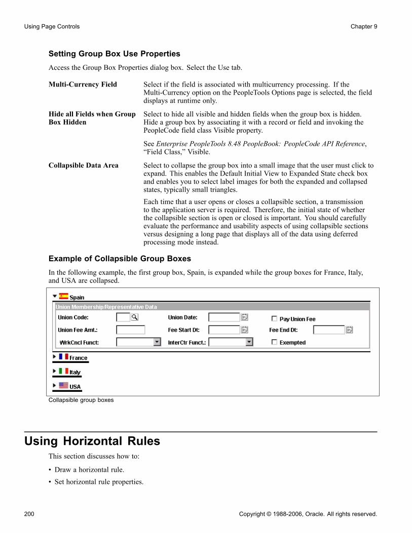
Using Page Controls Chapter 9
Setting Group Box Use PropertiesAccess the Group Box Properties dialog box. Select the Use tab.
Multi-Currency Field Select if the field is associated with multicurrency processing. If theMulti-Currency option on the PeopleTools Options page is selected, the fielddisplays at runtime only.
Hide all Fields when GroupBox Hidden
Select to hide all visible and hidden fields when the group box is hidden.Hide a group box by associating it with a record or field and invoking thePeopleCode field class Visible property.
See Enterprise PeopleTools 8.48 PeopleBook: PeopleCode API Reference,“Field Class,” Visible.
Collapsible Data Area Select to collapse the group box into a small image that the user must click toexpand. This enables the Default Initial View to Expanded State check boxand enables you to select label images for both the expanded and collapsedstates, typically small triangles.Each time that a user opens or closes a collapsible section, a transmissionto the application server is required. Therefore, the initial state of whetherthe collapsible section is open or closed is important. You should carefullyevaluate the performance and usability aspects of using collapsible sectionsversus designing a long page that displays all of the data using deferredprocessing mode instead.
Example of Collapsible Group BoxesIn the following example, the first group box, Spain, is expanded while the group boxes for France, Italy,and USA are collapsed.
Collapsible group boxes
Using Horizontal RulesThis section discusses how to:
• Draw a horizontal rule.• Set horizontal rule properties.
200 Copyright © 1988-2006, Oracle. All rights reserved.

Chapter 9 Using Page Controls
Drawing a Horizontal RuleTo draw a horizontal rule:
1. Select Insert, Horizontal Rule.2. Draw a horizontal line to the appropriate length on the page.
Setting Horizontal Rule PropertiesThis section discusses how to apply informational labels to a horizontal rule and configure how the horizontalrule is used on a page.
Setting Horizontal Rule Label PropertiesTo set horizontal rule label properties:
1. Open the Horizontal Rule Properties dialog box.2. On the Label tab, enter an information-only label to differentiate the line from other frames and lineson your field order list.
3. Select the style for the line.You can control the color and line thickness of a horizontal rule by specifying a style.
See Chapter 14, “Creating Style Sheet Definitions,” page 347.
Setting Horizontal Rule Use PropertiesAccess the Horizontal Rule Properties dialog box. Select the Use tab.
Multi-Currency Field See Chapter 10, “Creating Page Definitions,” Setting Use Properties, page 278.
Set to Level 0 Manipulate the occurs level of your controls on the page while still preservingthe physical tab order at runtime. If you adjust the sequence of fields on theOrder tab of the page definition, the tab order for the user at runtime isadjusted to that new order.
See Chapter 10, “Creating Page Definitions,” Level-Based Controls, page 252.Use this setting to specify a scroll level organization that differs from the orderof page fields on the Order tab. For example, you might want to create a pagethat contains multiple collapsing group boxes with each containing level-basedcontrols. By placing a horizontal rule between each of the collapsing sectionsand selecting Set to Level 0, you return the occurs level to 0 so that you canadd additional levels without having to alter the order of controls on the Ordertab. In doing so, you can maintain a consistent tab order.
Using ImagesThis section discusses how to:
• Adjust static image size and shape.
• Set static image properties.
Copyright © 1988-2006, Oracle. All rights reserved. 201

Using Page Controls Chapter 9
• Set image properties.
Understanding Static ImagesA static image is different from an image because it:
• Does not change at runtime.
• Is not associated with a record field.
Static images are associated with a predefined image definition. For example, you might select a static image,such as a yellow Clear button, from the image catalog and place it on top of a push button control so that theuser knows to click that button to clear the contents of the page.
Adjusting Static Image Size and ShapeYou can adjust the size of a static image by dragging the "handles" on the edge of the image box , or youcan adjust the size in the Static Image Properties dialog box on the Label tab by changing the width andheight in pixels.
Setting Static Image PropertiesTo associate a static image with an image definition:
1. Open the Static Image Properties dialog box.2. On the Label tab, select the label type.3. If you select Text, enter a label to identify your static image.The label does not appear on your page at runtime. Use it to track your images in your scroll orderlist box and on page definition reports.
4. Select an image ID using one of the following methods:• Select a predefined image definition from the Image ID drop-down list box.• Click the Browse button next to Image ID to preview the list of available images.The Select Image dialog box appears with a list of the image components available. To the right of thelist is a preview of the selected image.
Note. If an image definition is stored as a .GIF file, with no alternate format selected, it does not appearon the Layout tab of the page definition . A warning dialog box appears, telling you to convert the image.If you are not concerned about viewing the image during the design process, you can ignore the messagebecause the image will appear as intended on your page in the browser at runtime.
5. Click OK to return to the Static Image Properties dialog box.The image that you selected appears in the image area with its width and height displayed in pixels.
6. Set the format and size attributes for the image.
Scale Select to scale the image to the size of the frame that you set using thecontrol selection handles or by the width and height that you enter. Thescaling occurs when you view the page in a browser.
Size Select to display the image as is, regardless of the control size on the page.7. Click OK.
202 Copyright © 1988-2006, Oracle. All rights reserved.

Chapter 9 Using Page Controls
You can now position the static image anywhere on the page.
Note. You can define your own static images, such as your company logo, by creating a new image definition.After you create the image definition, you can then add your logo to a page using a static image control.
See Chapter 15, “Creating Image Definitions,” page 371.
Setting Image PropertiesTo associate a record definition with an image:
1. Open the Image Properties dialog box.2. On the Record tab, select the record and field names with which this image field is associated.3. Set the image format and size attributes.
Scale Select to scale the image to the size of the frame that you set using thecontrol selection handles or by the width and height that you enter. Thescaling occurs when you view the page in a browser.
Size Select to display the image as is, regardless of the control size on the page.
4. Specify the alignment of your image.
5. Select a style for the image.
Setting Image Label PropertiesBe sure to assign an informational label to your image. This is especially important if your application workswith screen reader software.
To document an image control with an informational label:
1. Enter a text description in the Alt tag for image region.2. Select one of the following settings from the Type drop-down list box:
None Select if you do not want a label. The Text field becomes unavailablefor entry.
Text Select to enter a custom label. This is the default setting.
Message Catalog Select to use a preset message from the message catalog. The Message Setand Msg Number (message number) fields become available for entry.
RFT Long (record field tablelong) and RFT Short (recordfield table short)
Select to use a preset label from the record field set on the Record tab. TheLabel ID drop-down list box becomes available for entry.
Setting Image Use PropertiesThe Use tab of the Image Properties dialog is the same as for that of an edit box.
See Chapter 10, “Creating Page Definitions,” Setting Use Properties, page 278.
Copyright © 1988-2006, Oracle. All rights reserved. 203
Using Page Controls Chapter 9
Using Static TextAccess the Static Text Properties dialog box.
Label Text
Text If you select Text, you can use either uppercase or lowercase characters. Thetext label is limited to 60 characters in length. You can also split your text iteminto multiple lines. To do this, position the cursor in the Text field where youwant the split to occur and click the Insert Line Feed button. A thick verticalbar character appears in the Text field, and when you close the dialog box,your text item is split into multiple lines.
Message Catalog If you select Message Catalog, enter the appropriate message set and number.As with a text label, you are limited to message catalog text of 60 characters.
StyleYou can control the color, font, size, and other characteristics of the text by specifying a style.
See Chapter 14, “Creating Style Sheet Definitions,” page 347.
AlignmentSet the horizontal alignment of your text control, as determined by the left-hand edge of the field. You canalign controls to the left-of-center, centered, or to the right-of-center.
Use TabIf a text item is associated with multicurrency processing, select the Multi-Currency Field option. This causesthe text item to appear at runtime only if the Multi-Currency option on the PeopleTools Options page is selected.
Using Check BoxesWhen you insert a check box on a page, it appears with a default label, Dummy Name, until you specify arecord definition name and field name, or a text label.
Setting Check Box PropertiesDefine the check box control by assigning the appropriate properties.
Setting Check Box Record PropertiesTo link check boxes with associated record definitions:
1. Open the Check Box Properties dialog box.
2. On the Record tab, select the record and field names from the drop-down list boxes.
3. Enter the enabled and disabled values for the check box.
204 Copyright © 1988-2006, Oracle. All rights reserved.
Chapter 9 Using Page Controls
For example, if the enabled value of the check box is Y for yes, and the check box is selected when the usersaves the row, the Y value is written to the database. If the disabled value of the check box is N for no, andthe check box is cleared when the user saves, the N value is written to the database.The enabled and disabled values that you enter validate against the Translate table. If a value isn’t found,the system displays a warning message but allows the value to remain. You might find this useful whenprototyping pages before defining record definitions.
Setting Check Box Label and Use PropertiesAfter you link the check box to a record definition and field, set the label properties. Otherwise, the defaultcheck box label is the field long name. Set how the check box will be used on the Use tab.
See AlsoChapter 10, “Creating Page Definitions,” Setting Page Field Properties for Controls, page 270
Chapter 10, “Creating Page Definitions,” Setting Use Properties, page 278
Using Drop-Down List BoxesThis section discusses how to:
• Set drop-down list box record properties.• Set drop-down list box label and use properties.
Setting Drop-Down List Box Record PropertiesTo set drop-down list box record properties:
1. Open the Drop-Down List Box Properties dialog box.
2. On the Record tab, associate the drop-down list box with a record and field.
3. Select a style.
Set the font and color attributes of your drop-down list box data.
See Chapter 14, “Creating Style Sheet Definitions,” page 347.4. Select a displayed text option:• Xlat Short.• Xlat Long.• Prompt Table Field.
5. If you selected Prompt Table Field, enter the field name in the Prompt Table Field area.6. Set the field size for the drop-down list box.
Setting Drop-Down List Box Label and Use PropertiesYou can set the label and use properties for a drop-down list box.
Copyright © 1988-2006, Oracle. All rights reserved. 205
Using Page Controls Chapter 9
See AlsoChapter 10, “Creating Page Definitions,” Setting Label Properties, page 275
Chapter 10, “Creating Page Definitions,” Setting Use Properties, page 278
Using Edit Boxes and Long Edit BoxesWhen you insert edit boxes and long edit boxes on a page, they appear with the default label, Dummy Name,until you specify a record and field for them or until you specify a text type field label. There is more spacethan required between your edit box label and the control. PeopleSoft provides 20 percent extra space for theedit box label for translation purposes.
You control source data, labels, and how the edit box is used in the respective edit box and long edit boxproperties dialog boxes in PeopleSoft Application Designer. The settings for these two controls are mostly thesame.
Note. A Long Edit Box does not limit the number of characters that a user can enter in the browser, regardlessof any limits defined in the underlying record field. As such, characters entered by the user that exceedthe field definition’s field length may be truncated. For example, if you enter 012345678901234 into aLong Edit Box associated with a field with a field length of 10, input would be truncated and saved to thedatabase as 0123456789. The system treats carriage returns (ASCII=13) and Line feeds (ASCII=10) thesame as any other character.
Display-Only Edit BoxesSome edit boxes should be display-only. You might want a page field to govern what is displayed in anothercontrol. In some cases, you might want the page control to be invisible because it is required by PeopleCode,but is not a field that is accessible by a user.
If you designate the long edit box as display-only, select the Expand Field When Display Only check box tohide the scroll and automatically expand the size of the edit box as necessary.
See AlsoEnterprise PeopleTools 8.48 PeopleBook: PeopleCode API Reference, “Field Class,” DisplayOnly
Chapter 10, “Creating Page Definitions,” Setting Use Properties, page 278
Using Radio ButtonsThis section provides an overview of radio buttons and discusses how to:
• Set radio button record properties.• Set radio button label properties.• Set radio button use properties.
206 Copyright © 1988-2006, Oracle. All rights reserved.
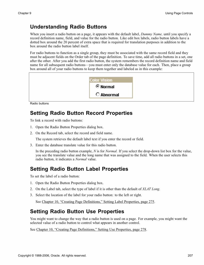
Chapter 9 Using Page Controls
Understanding Radio ButtonsWhen you insert a radio button on a page, it appears with the default label, Dummy Name, until you specify arecord definition name, field, and value for the radio button. Like edit box labels, radio button labels have adotted box around the 20 percent of extra space that is required for translation purposes in addition to thebox around the radio button label itself.
For radio buttons to function as a single group, they must be associated with the same record field and theymust be adjacent fields on the Order tab of the page definition. To save time, add all radio buttons in a set, oneafter the other. After you add the first radio button, the system remembers the record definition name and fieldname for all subsequent radio buttons—you must enter only the database value for each. Then, place a groupbox around all of your radio buttons to keep them together and labeled as in this example:
Radio buttons
Setting Radio Button Record PropertiesTo link a record with radio buttons:
1. Open the Radio Button Properties dialog box.
2. On the Record tab, select the record and field name.
The system retrieves the default label text if you enter the record or field.
3. Enter the database translate value for this radio button.
In the preceding radio button example, N is for Normal. If you select the drop-down list box for the value,you see the translate value and the long name that was assigned to the field. When the user selects thisradio button, it indicates a Normal value.
Setting Radio Button Label PropertiesTo set the label of a radio button:
1. Open the Radio Button Properties dialog box.2. On the Label tab, select the type of label if it is other than the default of XLAT Long.3. Select the location of the label for your radio button: to the left or right.
See Chapter 10, “Creating Page Definitions,” Setting Label Properties, page 275.
Setting Radio Button Use PropertiesYou might want to change the way that a radio button is used on a page. For example, you might want theselected value of a radio button to control what appears in another control.
See Chapter 10, “Creating Page Definitions,” Setting Use Properties, page 278.
Copyright © 1988-2006, Oracle. All rights reserved. 207

Using Page Controls Chapter 9
Using SubpagesThis section provides an overview of subpages and discusses how to:
• Define a subpage.
• Insert a subpage on a page.
• Specify informational subpage labels.
Understanding SubpagesSubpages are a powerful means of factoring out commonly used page functionality in your application. Ratherthan duplicating the same set of page fields on two or more pages, you can create a single subpage thatcontains those page fields and add it to any page. This makes it much easier to maintain the functionalitythat these page fields represent.
Subpages are even more effective when used with corresponding subrecords. In order to support the use ofsubrecords with subpages, the system uses a record name substitution mechanism for subpage-type page fields.Each subpage has a "from" record, determined dynamically by the page definition in PeopleSoft ApplicationDesigner and by the PeopleSoft Pure Internet Architecture. The "from" record is a record associated withone of the page fields in the subpage. Which page field depends upon the page field ordering, the types ofpage fields on the subpage, and whether it’s record is a subrecord. The subpage itself must be fully expandedin order to make this determination. (This is important to keep in mind when working with subpages thatcontain other subpages.)
The "to" record is specified by you in the SubPage Record Name Substitution group box in the InsertSubpage dialog box that displays after you insert the subpage into a page (and on the Subpage tab of theSubpage Properties dialog). At runtime, when a subpage-type page field is expanded, each page field thatis associated with the dynamically determined "from" record is instead associated with the "to" record youspecify. This means, for example, that a subpage can be populated with page fields that are associated with asubrecord so that the subrecord is determined to be the "from" record. Then when that subpage is used as asubpage-type page field, you can specify the "to" record as one of the records that contains that subrecord.This enables you to associate a single set of page fields (through the subpage) with a variety of differentrecords (each containing the subrecord).
Defining a SubpageCreating a subpage is just like creating a brand new page definition. The difference is that you define it as asubpage rather than a standard page in the Page Properties dialog box.
To define a subpage:
1. Select File, New, Page.2. Select File, Definition Properties to access the Page Properties dialog box.Use this dialog box to define the type, size, and layout of the page.
3. Select SubPage in the Page Type drop-down list box.4. Select the size of the page.
See Chapter 10, “Creating Page Definitions,” Changing Page Use Information, page 300.5. Select Adjust Layout for Hidden Fields if necessary.6. Select Allow Deferred Processing if appropriate.
208 Copyright © 1988-2006, Oracle. All rights reserved.
Chapter 9 Using Page Controls
See Chapter 8, “Designing Pages for Optimal Performance and Accessibility,” Understanding ProcessingModes, page 179.
Inserting a Subpage Into a PageAfter you create the subpage definition, insert a subpage control on your primary page and associate it withthe subpage definition.
To insert a subpage into a page:
1. Open the page on which you want to insert the subpage.2. Select Insert, SubPage.The Insert Subpage dialog box appears.
3. Select a subpage definition.Specify the name of the subpage that you want to insert into the open page definition.
4. Select a record definition in the SubPage Record Name Substitution group box.The subpage writes its fields to a generic record. Specify the application-specific record name to whichyou want the information in the subpage written.
See Chapter 9, “Using Page Controls,” Using Subpages, page 208.
Note. All of the fields in a subpage must be associated with fields of a subrecord in the specified recorddefinition.
5. Click OK.The subpage appears on the page. Its size reflects the size of the page control group, and it is identified bythe subpage definition name. During design time, the fields within the subpage are not visible. At runtime,pages containing subpages are dynamically expanded. Be sure to leave a few pixels of space between theleft edge of the main page and the subpage page field to ensure sufficient padding at runtime.
When saving a page with multiple subpages, be aware that you may receive a warning message if duplicatefields are present.
Inserting a Subpage Into a GridYou can insert a subpage into a grid as you would any other column.
See Chapter 9, “Using Page Controls,” Inserting and Manipulating Grid Columns, page 213.
Specifying Informational Subpage LabelsDocument the purpose of the subpage by changing the informational label of the subpage. The default subpagelabel is Subpage. Any label that you attach to a subpage is for information only—it doesn’t appear on the page,but it does appear on the page definition printout and in the control order list. Use labels to differentiate amongmultiple subpages on a page.
To change informational subpage labels:
1. Open the Subpage Properties dialog box.Note that the Subpage tab displays the information that you entered on the Insert Subpage dialog box.
2. On the Label tab, enter your informational text label.
Copyright © 1988-2006, Oracle. All rights reserved. 209

Using Page Controls Chapter 9
3. Enter the page field name in the General tab.4. (Optional) Select Enable as Page Anchor if you want the subpage to serve as a jump destination on the page.5. Click OK.
Using GridsThis section provides overviews of grids and discusses how to:
• Insert and resize grid controls.
• Insert and manipulate grid columns.
• Set column properties.
• Create a tabbed grid.
• Freeze grid columns.
• Use multiple grids on a page.
• Enable grid personalization.
• Set grid general properties.
• Set grid label properties.
• Set grid use properties.
Note. A specific type of grid called an analytic grid can be used exclusively for applications built for thePeopleSoft Analytic Calculation Engine.
See AlsoEnterprise PeopleTools 8.48 PeopleBook: PeopleSoft Analytic Calculation Engine, “Creating Analytic Grids”
Understanding Grid Control ScopeYou can insert these page controls into a grid:
• Check boxes.• Drop-down list boxes.• Edit boxes.• Long edit boxes.• Push buttons or links.• Images.• HTML areas.• Secondary pages.• Subpages.• Tab separators.
210 Copyright © 1988-2006, Oracle. All rights reserved.

Chapter 9 Using Page Controls
Note. When designing grids, use prompts in place of drop-down list boxes for better performance.
Understanding Grid PropertiesThe default grid displays:
• A data navigation bar at the top of the table that enables the user to page through additional rows of data.• Delete and Add buttons at the end of each row that enable the user to insert and delete rows in the grid.The inserted row appears under the current row. These buttons appear automatically as determined by thegrid properties (display-only, no row insert, and no row delete).
• An occurs count of 1.You can set the grid to be any size at design time and then set the occurs count to control the maximumnumber of rows to display at runtime.
There are three areas on a grid to which you can apply labels or image buttons to help the user navigate throughthe data in the grid. Set properties for these areas:
• Header• Body• Footer
Understanding Grid CustomizationPeopleSoft Application Designer enables the user to customize a grid at runtime. This feature is enabled bydefault as a Customize link on the Personalize tab of the Header Navigation Bar Properties dialog box.
Note. If you do not display the grid header bar, the Customize option is not available to the user unless youenable it for the footer area.
Copyright © 1988-2006, Oracle. All rights reserved. 211

Using Page Controls Chapter 9
Personalize Column and Sort Order page
When the user clicks the Customize link for a grid on a transaction page, the system opens the PersonalizeColumn and Sort Order page, where custom parameters can be set for that grid. This page contains a samplegrid that displays a few rows of real data from the buffer in display-only format. If there is no data in thebuffer for that grid, only the column headings appear. Tabs in the grid are active so that the user can viewall sample data.
From this customization page, users can control the column and sort order, as well as copy other users’ gridsettings or choose to share their settings with other users once they save their changes.
The Column Order grid displays the columns in their current order, including tab separators. The list of fields isdriven by the page definition but excludes columns that are hidden by PeopleCode. The user can hide columnsand change their sort order. Users can also freeze grid columns. Columns that you freeze at design timeautomatically appear to the user as already frozen. However, the user has the option of overriding this setting.
The Sort Order grid enables the user to control the ascending and descending sort of each column, with theexception of tab separators, images, push buttons, links, and HTML areas. Users can sort hidden fields,however. The default setting is ascending for each column.
After making changes, the user can accept, preview, restore defaults, or cancel selections. If the user saves thenew settings by selecting OK, the system stores the new settings as persistent values for that user based on akey structure. Therefore, each time the user accesses this grid, the system uses all personalization options thatwere set previously. The user can restore all default settings by selecting the Delete Settings link to remove allstored personalization settings from the database.
The user can override the persistent sort order directly on the transaction page by clicking the linked field labelto affect the sort. Clicking the link repeatedly toggles between ascending and descending sort order for thatcolumn. This type of sorting directly in the transaction page is not persistent.
212 Copyright © 1988-2006, Oracle. All rights reserved.
Chapter 9 Using Page Controls
Note. You can continue to implement the SortScrolls PeopleCode command, but the user can override thedefined sort with this feature.
Inserting and Resizing Grid ControlsTo insert a grid on a page:
1. Select Insert, Grid.2. To adjust the grid width, drag the horizontal or vertical control handles.The horizontal grid width should be roughly equivalent to the columns that you insert into the grid.Otherwise, your grid might appear wider than necessary at runtime.
Inserting and Manipulating Grid ColumnsThis section discusses how to:
• Insert grid columns.• Delete grid columns.• Move grid columns on the Layout tab.• Move grid columns on the Order tab.• Resize grid columns.
Inserting Grid ColumnsTo insert a grid column:
1. Use one of these methods to insert a column:• Select a page control from the Insert menu or the page control toolbar and click the grid.• Drag a page field from inside the current page or from another page.• Copy and paste a page field or record field.• Drag a definition (such as a record field, a page field, or an entire record definition) from the projectworkspace.The new location of the definition or control is determined by the location of the upper left-hand cornerof the drag rectangle, or by the mouse cursor if no drag rectangle appears. PeopleSoft ApplicationDesigner automatically places the first column on the left-hand side of the grid.
2. Click your mouse or release the field in the gray area of the grid.Place new columns to the right of existing columns by clicking or releasing the control in the gray area ofthe grid where no columns are present. To place a column between two grid columns, release the newcolumn in the first of the two columns.
When inserting subpages into your grid as a column, be aware that:
• You can insert subpages by dragging them from the project workspace or by cutting and pasting from thepage to the grid.
• Only one column displays in the grid in PeopleSoft Application Designer representing all fields in thesubpage.At runtime, all fields display in the order they appear on the Order tab of the subpage.
Copyright © 1988-2006, Oracle. All rights reserved. 213

Using Page Controls Chapter 9
• You cannot insert subpages that contain fields that are not allowed in grids such as static text or radio buttons.The system generates an error indicating the invalid field type. Similarly, if at a later point an invalid fieldtype is added to a subpage already in a grid, the system generates a runtime error when the user accesses thepage containing the subpage.
• The subpage you insert can contain fields that are associated with subrecord record fields.The same record name substitution mechanism that applies to subpages inserted onto a page applies tothose inserted as grid columns. The system replaces the name of the subrecord as part of the expansionprocess and it is never seen at runtime.
See Chapter 9, “Using Page Controls,” Understanding Subpages, page 208.
Deleting Grid ColumnsTo delete a grid column:
1. Select a column by right-clicking the column heading.
Be sure that you select only the column and not the grid as a whole; otherwise, you might delete the entiregrid instead of just the column. The grid is selected when control boxes appear around the edges of thegrid. The column is selected when it turns black.
2. Select Delete from the pop-up menu.
Moving Grid Columns on the Layout TabTo move grid columns on the Layout tab:
1. Select a column by clicking the column heading.
2. Drag the column to its new location.
3. Release the mouse button over the column that is to the left of the new location.
Moving Grid Columns on the Order TabTo move grid columns on the Order tab:
1. Select the column row by clicking the row number.
The grid and grid columns are clearly distinguished from other page fields on your page. The grid isidentified by the Type column. All columns in the grid are directly below in a lighter green. Nongrid pagefield rows are white.
2. Drag the row to the new position in the grid.
A red line indicates the new position of the column before you release it. You cannot move a columnoutside of the grid when working on the Order tab. Similarly, you cannot move an existing page field fromelsewhere on the page into the grid. Both of these operations can be performed on the Layout tab.
Resizing Grid ColumnsYou can resize grid columns in PeopleSoft Application Designer by dragging the right border of the columnheading.
Setting Column PropertiesAfter you insert the page control or field into your grid, you can set the properties for that field as you wouldset properties for any other page control. Access the field properties by double-clicking the column heading.
214 Copyright © 1988-2006, Oracle. All rights reserved.
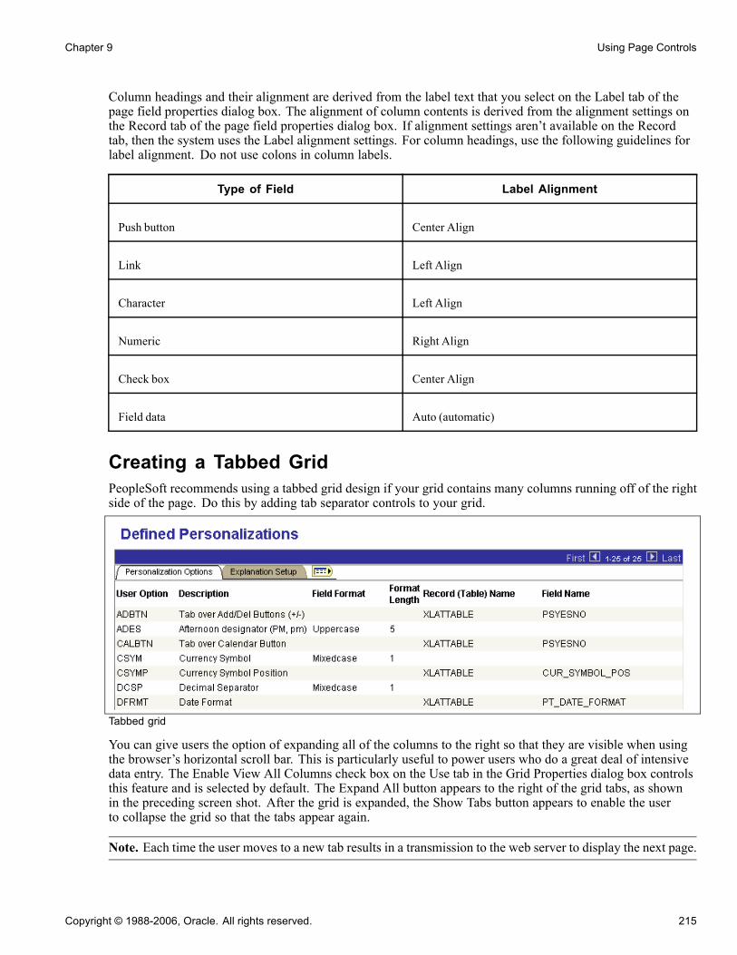
Chapter 9 Using Page Controls
Column headings and their alignment are derived from the label text that you select on the Label tab of thepage field properties dialog box. The alignment of column contents is derived from the alignment settings onthe Record tab of the page field properties dialog box. If alignment settings aren’t available on the Recordtab, then the system uses the Label alignment settings. For column headings, use the following guidelines forlabel alignment. Do not use colons in column labels.
Type of Field Label Alignment
Push button Center Align
Link Left Align
Character Left Align
Numeric Right Align
Check box Center Align
Field data Auto (automatic)
Creating a Tabbed GridPeopleSoft recommends using a tabbed grid design if your grid contains many columns running off of the rightside of the page. Do this by adding tab separator controls to your grid.
Tabbed grid
You can give users the option of expanding all of the columns to the right so that they are visible when usingthe browser’s horizontal scroll bar. This is particularly useful to power users who do a great deal of intensivedata entry. The Enable View All Columns check box on the Use tab in the Grid Properties dialog box controlsthis feature and is selected by default. The Expand All button appears to the right of the grid tabs, as shownin the preceding screen shot. After the grid is expanded, the Show Tabs button appears to enable the userto collapse the grid so that the tabs appear again.
Note. Each time the user moves to a new tab results in a transmission to the web server to display the next page.
Copyright © 1988-2006, Oracle. All rights reserved. 215

Using Page Controls Chapter 9
To create a tabbed grid:
1. Insert a grid control on the page.
2. Insert the columns to appear on the first tab.
3. Insert a tab separator control after the last column.
4. Set the tab separator properties.a. Double-click the tab separator to access the Tab Separator Properties dialog box.b. Specify the label properties on the Label tab.c. Specify the general properties on the General tab.
5. Insert the next set of columns to appear on the second tab.
Alternatively, you can place all of the columns in your grid first and then insert the tab separator betweenthe two columns that you want separated.
6. Repeat steps 3 and 4 if necessary.
7. Set the tab separator properties by double-clicking the column heading of the tab separator.a. On the Label tab, specify the label type.
Select None, Text, orMessage Catalog. If you select Text, enter the label text and select the label alignment.The label text that you select appears on the tab in the grid.
b. On the General tab, determine whether you want to enable the tab separator as a page anchor.If so, select the Enable as Page Anchor check box and enter a page field name.
Freezing Grid ColumnsYou can freeze the first column or the first several columns in a tabbed grid so that they appear on subsequenttabs. To freeze more than one column, select the freeze option for each column that you want to appear onthe following tab.
Freezing grid columns impacts the horizontal scrolling ability of the grid at design time. If you freeze a gridcolumn that is not visible inside the boundaries of the grid at design time, you are not able to view all columnsin your grid. Lengthen the width of your grid to accommodate all columns.
Freeze a grid column by selecting the Freeze Grid Column check box on the Use tab of the properties dialogbox for that column. Note that the effects of selecting this attribute are visible only at runtime.
Using Multiple Grids on a PageYou can place as many grids on a page as you want, provided that they are at the same occurs level. They canbe one above the other or they can be side-by-side, such as those in the following example. This is helpfulwhen you must transfer data from one grid to another without switching between pages.
In the following example, the user can transfer data from the Source Competencies grid on the right to theAssigned Competencies grid on the left by using the double left arrow button. The push button is associatedwith a PeopleCode program, enabling it to transfer the data between the two grids.
216 Copyright © 1988-2006, Oracle. All rights reserved.

Chapter 9 Using Page Controls
Grids side-by-side on a page
As you can with other level-based controls, you can nest a grid in a scroll area or scroll bar. However, youcannot nest a grid in another grid.
Enabling Grid PersonalizationTo disable grid personalization:
1. Open the Grid Properties dialog box.
2. Select the Label tab.
3. Click the Properties button for the header navigation bar.
This opens the Header Navigation Bar Properties dialog box.
4. Select the Personalize tab.
5. Select the Invisible check box.
6. Click the OK button.
To enable grid personalization in the navigation footer:
1. Open the Grid Properties dialog box.2. Select the Label tab.3. Select the Display Navigation Bar check box in the Footer Area group box.4. Click the Properties button for the footer navigation bar.This opens the Footer Navigation Bar Properties dialog box.
5. Select the Personalize tab.6. Clear the Invisible check box.
Copyright © 1988-2006, Oracle. All rights reserved. 217
Using Page Controls Chapter 9
7. Click the OK button.
Setting Grid General PropertiesAccess the Grid Properties dialog box.
Main Record Select the record that contains most of the fields that you want to use in thegrid. Fields that you display in the grid that are not from the main recordshould be display-only or related fields, which you can set on the Use tab ofthe properties dialog box for that column.
Page Field Name Enter a name for the grid. The default is the main record for the grid,however, you can rename the grid as long as it is a unique name for thepage or component. This name is used by the PeopleCode GetGrid functionto create a grid definition.
See Enterprise PeopleTools 8.48 PeopleBook: PeopleCode API Reference,“File Class” and Enterprise PeopleTools 8.48 PeopleBook: PeopleCodeLanguage Reference, “PeopleCode Built-in Functions,” GetGrid.
Occurs Level Enter a 1, 2, or 3 to represent at which level the grid resides on the page.Having an occurs level for the grid enables you to designate the hierarchicalparent-child relationship. Entering 1 specifies that the grid is at the first level.Entering 2 specifies that a grid is at the second level and is a child of, or nestedin, the first level of data, and so on up to 3. A grid can be nested in anotherlevel-based control, but it cannot be nested in another grid.
See Chapter 10, “Creating Page Definitions,” Level-Based Controls, page 252.
Occurs Count Enter the number of rows to display initially at runtime.
See Chapter 10, “Creating Page Definitions,” Multiple Occurrences of Data,page 256.
Unlimited Occurs Count Select instead of setting an occurs count if you want the system to displayall rows of data in the buffer for this grid. Navigation links do not appear atruntime and the size of the grid depends on the number of rows in the buffer.
Enable as Page Anchor Select to apply an anchor tag to serve as a jump destination on the page.
Setting Grid Label PropertiesAccess the Grid Properties dialog box. Select the Label tab.
218 Copyright © 1988-2006, Oracle. All rights reserved.
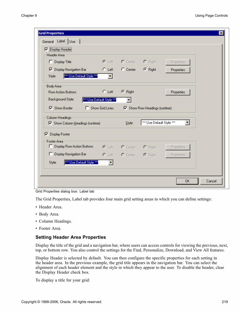
Chapter 9 Using Page Controls
Grid Properties dialog box: Label tab
The Grid Properties, Label tab provides four main grid setting areas in which you can define settings:
• Header Area.• Body Area.• Column Headings.• Footer Area.
Setting Header Area PropertiesDisplay the title of the grid and a navigation bar, where users can access controls for viewing the previous, next,top, or bottom row. You also control the settings for the Find, Personalize, Download, and View All features.
Display Header is selected by default. You can then configure the specific properties for each setting inthe header area. In the previous example, the grid title appears in the navigation bar. You can select thealignment of each header element and the style in which they appear to the user. To disable the header, clearthe Display Header check box.
To display a title for your grid:
Copyright © 1988-2006, Oracle. All rights reserved. 219
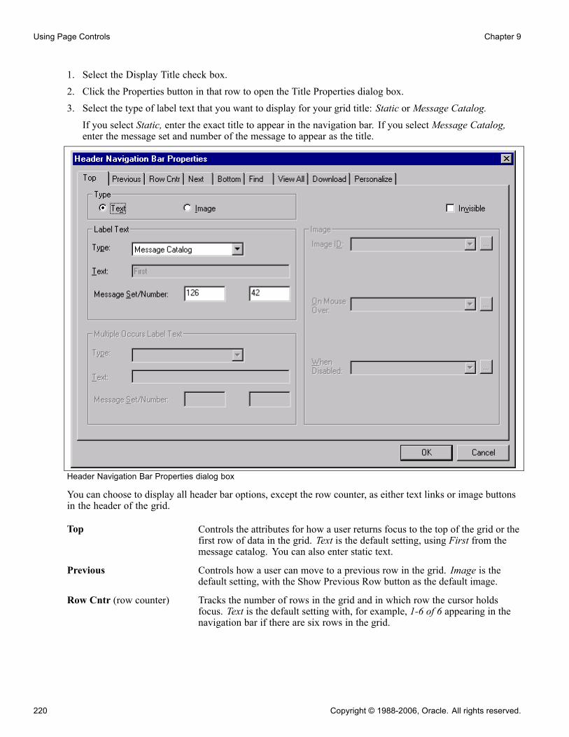
Using Page Controls Chapter 9
1. Select the Display Title check box.2. Click the Properties button in that row to open the Title Properties dialog box.3. Select the type of label text that you want to display for your grid title: Static or Message Catalog.If you select Static, enter the exact title to appear in the navigation bar. If you select Message Catalog,enter the message set and number of the message to appear as the title.
Header Navigation Bar Properties dialog box
You can choose to display all header bar options, except the row counter, as either text links or image buttonsin the header of the grid.
Top Controls the attributes for how a user returns focus to the top of the grid or thefirst row of data in the grid. Text is the default setting, using First from themessage catalog. You can also enter static text.
Previous Controls how a user can move to a previous row in the grid. Image is thedefault setting, with the Show Previous Row button as the default image.
Row Cntr (row counter) Tracks the number of rows in the grid and in which row the cursor holdsfocus. Text is the default setting with, for example, 1-6 of 6 appearing in thenavigation bar if there are six rows in the grid.
220 Copyright © 1988-2006, Oracle. All rights reserved.
Chapter 9 Using Page Controls
Note. The row count that appears is controlled by the occurs count that youset on the General tab in the Grid Properties dialog box (unless the userdisplays all). Using the previous example, if the occurs count is set to 5,then the row counter is 1-5 of 6.
Next Brings focus to the next row in the grid. Image is the default setting with theShow Next Row button appearing to the right of the row counter.
Bottom Controls the attributes for how a user moves focus to the last row of thegrid. Text is the default setting, using Last from the message catalog. Youcan also enter static text.
Find Displays a link that enables the user to search any field in the grid or scrollarea. You can select either text or an image to represent the find feature. TheFind feature searches for matches in edit boxes, display-only fields, disabledfields, dynamic links, and text in long edit boxes. It does not find columnheadings, field labels, text values in icons, static links, and hidden fields,nor does it search outside the grid.
View All Enables the user to view all rows of data at once. Text is the default settingusing View All as the message catalog entry.
Download Available for grids only. Displays a download image button in the headeror footer bar that enables users to download all active, unhidden rows to aMicrosoft Excel spreadsheet, regardless of how many rows are visible on thescreen. The default for this setting in the header area is Invisible. For the footerarea of a grid, the download button appears by default when you select theDisplay Navigation Bar check box in the Footer Area group box of the Labeltab in the Grid Properties dialog box.
Note. Microsoft Excel may display Unicode comma-delimited data differentlybecause Microsoft Excel may be expecting a tab-delimited file. If displayabnormalities occur, you have two options.
In Microsoft Excel, after highlighting the first column, you can select Data,Text to Columns and select the options required to set Microsoft Excel toexpect a comma-delimited file.
Or, in PeopleSoft Application Designer change the file layout fromcomma-delimited to tab-delimited. Keep in mind that changing the filelayout properties in PeopleSoft Application Designer could cause the data tochange such that other applications may no longer recognize the data. Also,changing the file layout properties may impact more than one application, ifthat file layout is shared.
Customize Available for grids only. Displays a Customize link in the header bar thatenables the user to access all grid customization options.
See Chapter 9, “Using Page Controls,” Enabling Grid Personalization, page217.
To define the navigation bar properties:
1. Select the Properties button next to Display Navigation Bar.
Copyright © 1988-2006, Oracle. All rights reserved. 221
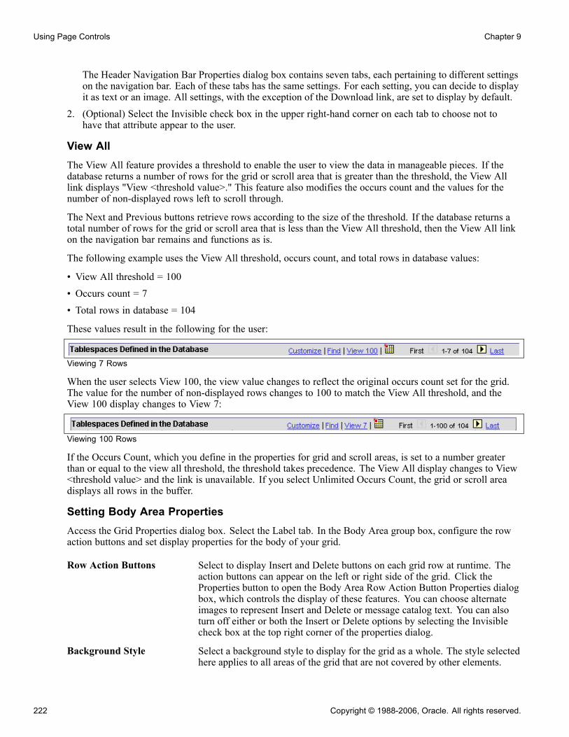
Using Page Controls Chapter 9
The Header Navigation Bar Properties dialog box contains seven tabs, each pertaining to different settingson the navigation bar. Each of these tabs has the same settings. For each setting, you can decide to displayit as text or an image. All settings, with the exception of the Download link, are set to display by default.
2. (Optional) Select the Invisible check box in the upper right-hand corner on each tab to choose not tohave that attribute appear to the user.
View AllThe View All feature provides a threshold to enable the user to view the data in manageable pieces. If thedatabase returns a number of rows for the grid or scroll area that is greater than the threshold, the View Alllink displays "View <threshold value>." This feature also modifies the occurs count and the values for thenumber of non-displayed rows left to scroll through.
The Next and Previous buttons retrieve rows according to the size of the threshold. If the database returns atotal number of rows for the grid or scroll area that is less than the View All threshold, then the View All linkon the navigation bar remains and functions as is.
The following example uses the View All threshold, occurs count, and total rows in database values:
• View All threshold = 100• Occurs count = 7• Total rows in database = 104
These values result in the following for the user:
Viewing 7 Rows
When the user selects View 100, the view value changes to reflect the original occurs count set for the grid.The value for the number of non-displayed rows changes to 100 to match the View All threshold, and theView 100 display changes to View 7:
Viewing 100 Rows
If the Occurs Count, which you define in the properties for grid and scroll areas, is set to a number greaterthan or equal to the view all threshold, the threshold takes precedence. The View All display changes to View<threshold value> and the link is unavailable. If you select Unlimited Occurs Count, the grid or scroll areadisplays all rows in the buffer.
Setting Body Area PropertiesAccess the Grid Properties dialog box. Select the Label tab. In the Body Area group box, configure the rowaction buttons and set display properties for the body of your grid.
Row Action Buttons Select to display Insert and Delete buttons on each grid row at runtime. Theaction buttons can appear on the left or right side of the grid. Click theProperties button to open the Body Area Row Action Button Properties dialogbox, which controls the display of these features. You can choose alternateimages to represent Insert and Delete or message catalog text. You can alsoturn off either or both the Insert or Delete options by selecting the Invisiblecheck box at the top right corner of the properties dialog.
Background Style Select a background style to display for the grid as a whole. The style selectedhere applies to all areas of the grid that are not covered by other elements.
222 Copyright © 1988-2006, Oracle. All rights reserved.

Chapter 9 Using Page Controls
Show Border Select to display a standard border around your grid. The default is selected.
Show Grid Lines Select to show grid lines on the grid. The default is to not display grid lines(cleared).
Show Row Headings(runtime)
Select to number rows at runtime. This option is selected by default.
Note. The row headings column still appears at design-time even if Show Row Headings (runtime) is notselected. This enables you to more easily select the grid if necessary.
Click the Properties button in the Body Area group box of the Grid Properties, Label tab to open the BodyArea Row Action Button Properties dialog box. It contains two tabs: Insert and Delete. The default settings forthese buttons are to display the Insert and the Delete buttons. Alternatively, you can select static or messagecatalog text, or you can make these items invisible so that they do not appear.
Body Area Row Action Button Properties dialog box
Setting Column Heading PropertiesAccess the Grid Properties dialog box. Select the Label tab.
You can set the grid to display column headings, and you can select the style in which to display them.Select a predefined column heading style from the drop-down list box or use the default. Changing stylesalters the foreground, background, and font in the column headings, making it different from the data rows.The default for Show Column Headings is selected.
Copyright © 1988-2006, Oracle. All rights reserved. 223
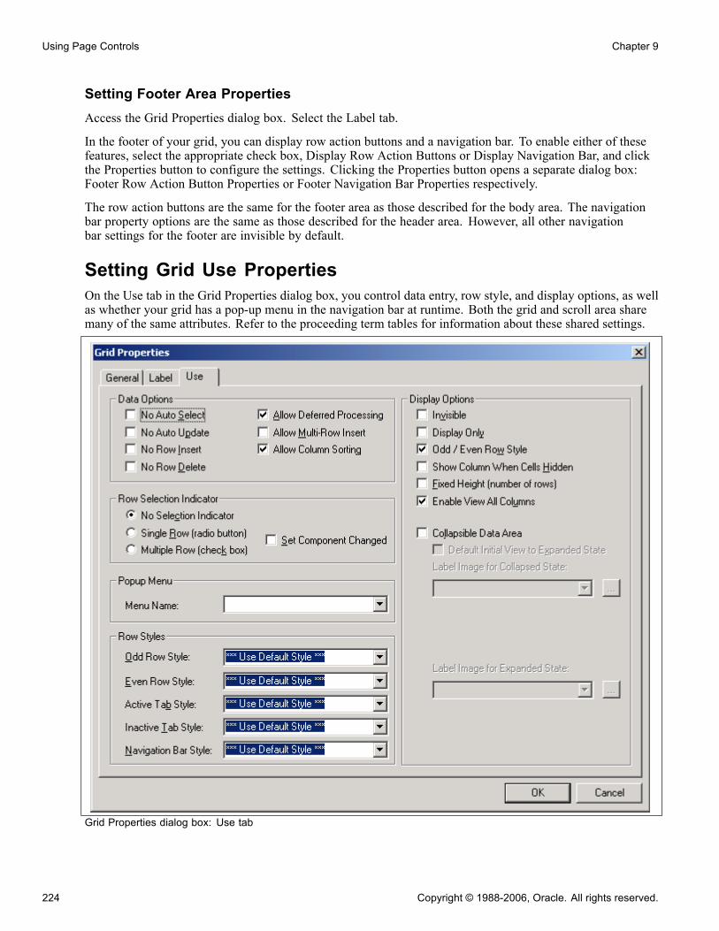
Using Page Controls Chapter 9
Setting Footer Area PropertiesAccess the Grid Properties dialog box. Select the Label tab.
In the footer of your grid, you can display row action buttons and a navigation bar. To enable either of thesefeatures, select the appropriate check box, Display Row Action Buttons or Display Navigation Bar, and clickthe Properties button to configure the settings. Clicking the Properties button opens a separate dialog box:Footer Row Action Button Properties or Footer Navigation Bar Properties respectively.
The row action buttons are the same for the footer area as those described for the body area. The navigationbar property options are the same as those described for the header area. However, all other navigationbar settings for the footer are invisible by default.
Setting Grid Use PropertiesOn the Use tab in the Grid Properties dialog box, you control data entry, row style, and display options, as wellas whether your grid has a pop-up menu in the navigation bar at runtime. Both the grid and scroll area sharemany of the same attributes. Refer to the proceeding term tables for information about these shared settings.
Grid Properties dialog box: Use tab
224 Copyright © 1988-2006, Oracle. All rights reserved.
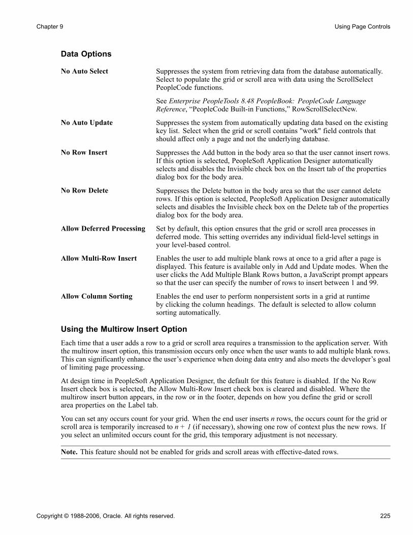
Chapter 9 Using Page Controls
Data Options
No Auto Select Suppresses the system from retrieving data from the database automatically.Select to populate the grid or scroll area with data using the ScrollSelectPeopleCode functions.
See Enterprise PeopleTools 8.48 PeopleBook: PeopleCode LanguageReference, “PeopleCode Built-in Functions,” RowScrollSelectNew.
No Auto Update Suppresses the system from automatically updating data based on the existingkey list. Select when the grid or scroll contains "work" field controls thatshould affect only a page and not the underlying database.
No Row Insert Suppresses the Add button in the body area so that the user cannot insert rows.If this option is selected, PeopleSoft Application Designer automaticallyselects and disables the Invisible check box on the Insert tab of the propertiesdialog box for the body area.
No Row Delete Suppresses the Delete button in the body area so that the user cannot deleterows. If this option is selected, PeopleSoft Application Designer automaticallyselects and disables the Invisible check box on the Delete tab of the propertiesdialog box for the body area.
Allow Deferred Processing Set by default, this option ensures that the grid or scroll area processes indeferred mode. This setting overrides any individual field-level settings inyour level-based control.
Allow Multi-Row Insert Enables the user to add multiple blank rows at once to a grid after a page isdisplayed. This feature is available only in Add and Update modes. When theuser clicks the Add Multiple Blank Rows button, a JavaScript prompt appearsso that the user can specify the number of rows to insert between 1 and 99.
Allow Column Sorting Enables the end user to perform nonpersistent sorts in a grid at runtimeby clicking the column headings. The default is selected to allow columnsorting automatically.
Using the Multirow Insert OptionEach time that a user adds a row to a grid or scroll area requires a transmission to the application server. Withthe multirow insert option, this transmission occurs only once when the user wants to add multiple blank rows.This can significantly enhance the user’s experience when doing data entry and also meets the developer’s goalof limiting page processing.
At design time in PeopleSoft Application Designer, the default for this feature is disabled. If the No RowInsert check box is selected, the Allow Multi-Row Insert check box is cleared and disabled. Where themultirow insert button appears, in the row or in the footer, depends on how you define the grid or scrollarea properties on the Label tab.
You can set any occurs count for your grid. When the end user inserts n rows, the occurs count for the grid orscroll area is temporarily increased to n + 1 (if necessary), showing one row of context plus the new rows. Ifyou select an unlimited occurs count for the grid, this temporary adjustment is not necessary.
Note. This feature should not be enabled for grids and scroll areas with effective-dated rows.
Copyright © 1988-2006, Oracle. All rights reserved. 225

Using Page Controls Chapter 9
At runtime, the system administrator controls the display and the default of this setting, as well as whether theend user has the option of overriding the default. The system administrator can disable multirow insert byclearing the Enable Option for Multiple Row Insert on the Administer Personalizations page in Security. Ifthe option is not disabled by the system administrator, the user can disable this setting on the Personalizationpage by selecting PeopleTools, Security, Use, My Profile. Here, the user can override the default of Yes byentering No in the Override Value edit box. When the user disables this feature, the multirow Add buttonis replaced with the standard Add button in all grids and scroll areas.
When the user saves the page, normal save processing runs, including save-edits on all rows. New, unchangedrows are not saved. After save processing, new, unchanged (and hence unsaved) rows are deleted from thebuffer. The only exception is when there is only one row and it is new and unchanged. This row remains in thebuffer, even though it has not been saved, because there must always be one row in any rowset.
For the end user pressing ALT+7 works the same with the multirow Add button as it does with the standardAdd button.
Row Selection IndicatorThese options enable the user to select one or more rows in the grid and scroll area. At runtime, indicatorsappear to the left of row numbers for grids and in the upper left corner for scroll areas. A transmission to theserver triggers the selection of the row or rows that the user designates.
No Selection Indicator This is the default selection. Prevents the user from selecting rows in thePeopleSoft Pure Internet Architecture.
Single Row (radio button) Enables the user to select a single row in a grid or scroll area. Inserts a radiobutton to the left of each row that the user can select.
Multiple Row (check box) Enables the user to select multiple rows in a grid or scroll area. Inserts acheck box to the left of each row that the user can select. Users can selectas many rows as needed.
Set Component Changed Enables the user to receive a save warning if a change is made to a rowselection indicator in the grid. PeopleSoft Pure Internet Architecture runtimeuses this option to set the PPR_CHANGED flag. This option is clearedby default.
This property ensures that if there are any changes to the grid, the datais saved to the database.
If you disable this property, this means that any row insert, row delete, orfield change on the rowset using PeopleCode would not cause the system totreat the component data as changed.
Note. For the row selection options, PeopleCode can change the selected property, which affects whichboxes are selected when the page is regenerated.
Popup MenuSelect a preset pop-up menu from the drop-down list box. The pop-up menu button appears in the left-handcorner of the navigation header at runtime.
See Chapter 12, “Creating Menu Definitions,” Creating Pop-up Menus, page 335.
226 Copyright © 1988-2006, Oracle. All rights reserved.

Chapter 9 Using Page Controls
Row StylesYou can control the color, font, and other characteristics of a row, active tab, inactive tab, and navigation barby specifying a style in the drop-down list box for each of the row style options.
Display Options
Invisible Select to make the grid or scroll area and its associated fields and recordsinvisible. Invisible is used for work grids or scrolls where you want theunderlying processing to be transparent to users. Typically, you associateinvisible work grids and scrolls with PeopleCode Scroll functions that enableyou to further control application processing.
Display Only In some cases, you might design grids that enable users to view but not changeinformation. Select this check box if you do not want the user to enter datainto the fields in any of the rows.
Odd/Even Row Style Selected by default, this attribute displays the grid with contrasting colors byrow. The Odd Row Style and Even Row Style drop-down list box optionsappear instead of the single Row Style option in the Row Styles group box.
Show Column When CellsHidden
Select if you want the columns to appear even if all of the cells in a column arehidden. Columns do not collapse.
Fixed Height (numberof rows)
Select to set the grid to a height corresponding to the number of rows in theoccurs count attribute. The grid remains fixed at that height even if the actualnumber of data rows varies from that number. If the fixed height property isnot used, the size of the grid dynamically changes based on the occurs countand the number of data rows retrieved.
Enable View All Columns Displays an expand all button to the right of a tabbed grid, enabling the userto view all columns of the grid by scrolling to the right using the browser’shorizontal scroll bar instead of selecting the grid tabs. The show grid tab buttonappears when columns are expanded to enable the user to view the tabs again.
Collapsible Data Area Select to collapse the data area for your grid or scroll area into a header barwith a small image that the user must click to activate or expand it. Thisenables the Default Initial View to Expanded State check box. You can thenselect the label image to represent the collapsed and expanded states.
Expanded grid
Collapsed grid
Copyright © 1988-2006, Oracle. All rights reserved. 227

Using Page Controls Chapter 9
Using HTML AreasThis section provides an overview of HTML area controls and discusses how to:
• Insert an HTML area.
• Populate an HTML area.
• Change an HTML area label.
Understanding HTML Area ControlsYou can insert an HTML area control on any PeopleSoft page. It can be inserted at any level on a page and caneven be placed in a grid control. This control is rectangular and can be resized easily.
Populate the HTML area control in one of these ways:
• Statically, in the page field property sheet.• Dynamically, by associating the control with a record field or HTML definition.
If the control is linked to a record field, the value of the record field is displayed in the HTML area. UsePeopleCode to associate the HTML area control with a predefined HTML definition.
When using HTML areas, consider:
• HTML areas are downloaded to Excel as a non-breaking space ( ).• HTML areas are not searched with the Find feature.
Generating Trees in HTML AreasYou can use the GenerateTree PeopleCode function with HTML areas. This example shows the tree that iscreated by the GenerateTree PeopleCode function next to a grid in a frame:
Tree in an HTML area
228 Copyright © 1988-2006, Oracle. All rights reserved.
Chapter 9 Using Page Controls
Populating an HTML AreaYou can populate an HTML area either statically, using the HTML Area Properties dialog box, or dynamically,by associating the control with a record field. Because the HTML that you write is included in the HTML thatis dynamically generated by the system at runtime, consider the following:
• The HTML that you include can affect the layout of the page.Being true to the design-time sizing of the HTML area is the best way to ensure that you do not affect thelayout of the other page field controls. Adding an invisible frame around the HTML area control canhelp ensure that you don’t affect other page fields.
• You can use only certain types of HTML tags. These tags are not supported by the HTML area control:- <body>- <frame>- <frameset>- <form>- <head>- <html>- <meta>- <title>
Using JavaScript in HTML AreasIf an HTML area contains a reference to third party JavaScript, you need to include the absolutizedattribute in the script tag and set it to"false". For example,
<script type="text/javascript" language="javascript" absolutized="false" src="../../../../../
See AlsoEnterprise PeopleTools 8.48 PeopleBook: PeopleCode Developer’s Guide, “Understanding HTML Trees andthe GenerateHTML Function,” Using the GenerateTree Function
Inserting an HTML AreaTo insert an HTML area on a page:
1. Select Insert, HTML Area.2. Draw the HTML area on your page.3. Move the HTML area control by dragging it with the mouse or by pressing the arrow keys.
Populating an HTML AreaThis section discusses how to:
• Populate an HTML area statically.
• Populate an HTML area dynamically.
Copyright © 1988-2006, Oracle. All rights reserved. 229

Using Page Controls Chapter 9
Populating an HTML Area StaticallyUse the HTML Area Properties dialog box to populate an HTML area.
HTML Area Properties dialog box with constant text
To populate an HTML area statically:
1. Access the HTML Area Properties dialog box.
2. On the HTML tab, select Constant as the value type.
3. In the long edit box, enter the HTML code that you want to display in the HTML area.
Populating an HTML Area DynamicallyTo populate an HTML area dynamically:
1. Access the HTML Area Properties dialog box.
2. On the HTML tab, select Field as the value type.
3. Specify the record and field to which you want to associate the HTML area control.
The value of the record field generates the HTML code that is included at runtime in the HTML area.
Note. When you associate an HTML area control with a field, make sure that the field is long enough tocontain the data that you want to pass to it. For example, if you associate an HTML area control with afield that is only 10 characters long, only the first 10 characters of your text are displayed. PeopleSoftrecommends using long character fields for record fields that are associated with an HTML area control.
230 Copyright © 1988-2006, Oracle. All rights reserved.

Chapter 9 Using Page Controls
Changing an HTML Area LabelAssign a distinct label to your HTML area to distinguish it from other HTML area controls on the Ordertab of the page.
To change an HTML area label:
1. Access the HTML Area Properties dialog box.2. Select the Label tab.3. Enter a brief text description of the HTML area.This label does not display at runtime; however, it appears on the Order tab of the page definition.
Using Push Buttons and LinksThis section provides an overview of push buttons and links and discusses how to:
• Insert a push button or link.
• Specify destination types.
• Specify a label for the push button or link.
Understanding Push Buttons and LinksPeopleSoft Pure Internet Architecture supports these features for this control:
• Selecting link style.• Selecting these types of push buttons and links:- External link.- Internal link.- Prompt action.- Scroll action.- Toolbar action.
• Selecting these image options:- On mouse over.- When disabled.
Inserting a Push Button or LinkAfter you add a push button or link control to your page you can define the attributes by opening the PushButton/Hyperlink Properties dialog box.
To insert a push button or link:
1. Select Insert, Push Button/Hyperlink.
2. Click where you want the upper, left-hand corner of the control to begin.
Copyright © 1988-2006, Oracle. All rights reserved. 231
Using Page Controls Chapter 9
A push button of small image size appears.3. Double-click the push button to access the Push Button/Hyperlink Properties dialog box.4. On the Type tab, select whether the control appears as a push button or link.5. Select a destination type from the Destination drop-down list box.
See Chapter 9, “Using Page Controls,” Specifying Destination Types, page 232.
6. Select the record and field names with which you want to associate the push button or link.
7. Select any of the remaining Type options:
Enable When Page isDisplay Only
Select to make the push button or link available to users who havedisplay-only access to this page.Display-only access is set per user and user class in Security.
Open in New Window Select to have the page that is displayed by the URL to appear in a newwindow, as opposed to replacing the existing window.
Activate by Enter Key Select to activate the push button or link when the user presses the ENTERkey. You can have more than one push button or link with this featureset per page, as long as only one of these fields is enabled at runtime.Otherwise, only one push button or link with this attribute enabled isallowed per page. This feature is available for all control types exceptexternal links.When using Activate by Enter Key in a scroll area or grid with an occurscount greater than one, the ENTER key triggers the first row only.Note that on a secondary page with the standard OK and Cancel buttonsenabled, the ENTER key activates the OK button rather than a custombutton or link.
Set Component Changed Select to enable the ComponentChanged built-in PeopleCode functionwhen the user selects the push button or link. This issues a save warning ifthe user attempts to leave the page. This setting is cleared by default.
See Enterprise PeopleTools 8.48 PeopleBook: PeopleCode LanguageReference, “PeopleCode Built-in Functions,” ComponentChanged.
Specifying Destination TypesAccess the Push Button/Hyperlink Properties dialog box.
232 Copyright © 1988-2006, Oracle. All rights reserved.

Chapter 9 Using Page Controls
Push Button/Hyperlink Properties dialog box: Type tab
TypeEach destination type that you select enables a different region on the Type tab, enabling you to further defineyour push button or link. Select one of these values from the Destination drop-down list box:
External Link Accesses a uniform resource locator (URL). You can select a value from theURL table or use the value of a record field to define the destination.Selecting this option enables the External Link group box. You can chooseto have the URL encoded or not by selecting the Encoded by Applicationcheck box.This applies an external link to your page in the form of a push button or linkthat accesses a new page, taking the user to the external website that youdesignate. To return to the primary page, the user closes the new page. Whensetting the record and field name consider these points:
Copyright © 1988-2006, Oracle. All rights reserved. 233

Using Page Controls Chapter 9
• If you specify a dynamic external link, you must enter a record nameand field name.The system uses the value of the record and field specified as the value ofthe link.
• Whether the external link is static or dynamic, you can use the specifiedrecord and field names to control the page field in PeopleCode when youwant to, for example, hide the link dynamically with PeopleCode.
• The "tool tip," or mouse over text, that appears with the link at runtimecomes from the RFT long label assigned to the record field.However, the RFT long label displays only if it is different from the assigneddisplay value of the link and it is not null. If the link is displayed as an imagebutton, the tool tip is derived from the label text if there is any. Otherwise,the RFT long label is used.
Internal Link Accesses a PeopleSoft page. Parameters include the menu path to the page anda check box to specify whether data from the current page should be usedin the search dialog box.Selecting this option enables the Internal Link group box.This adds an internal link in the form of a push button or link that you canuse to access another component or page from within the system or anotherPeopleSoft database or node. You can even specify the type of action modeto open in for that page. To control the push button or link in PeopleCode,enter the record and names.Like the external link, if you associate a record and field name with this link,the tool tip that appears at runtime draws from the RFT long label for therecord field. However, the RFT long label only displays if it is different fromthe assigned display value of the link.
Instant Messaging Action Select to add an instant messaging button to the page. Associate the buttonwith a record field that contains entries in the form of <user>@network (suchas John@Yahoo). For this purpose we provide the MCFIMNETWORKStable. The MCFIMDOMAIN field is the source for the instant messagingnetwork providers. This table contains only three network providers: AOL,Yahoo, and SameTime Connect. You should never enter additional networksnot already in this table.
See Enterprise PeopleTools 8.48 PeopleBook: PeopleSoft MultiChannelFramework, “Configuring Instant Messaging”.
Page Anchor Enables the user to jump to the anchor tag that you designate for a page fieldon the General tab of the properties dialog box for that field.This enables the user to jump from one destination (the link that you assign asthe page anchor) to another (the field that you enable as the page anchor) inyour page. When you select this option, the page fields that you previously setas page anchors on the General tab of the properties dialog box appear in theRelated Control drop-down list box in the Actions group box. You can place asmany page anchor buttons or links on the page as necessary.
PeopleCode Command Associates with a field in a record, so when the user clicks the push button orlink, the system runs any FieldChange PeopleCode that is associated with that
234 Copyright © 1988-2006, Oracle. All rights reserved.
Chapter 9 Using Page Controls
field. Enter the record and field names. The field should have PeopleCodein the FieldChange event.
Process Runs processes that you set up previously with PeopleSoft Process Scheduler.Associate process push buttons with a specific process definition; the processis run each time that a user clicks the button.Selecting this value enables the Process group box, where you can specify thetype and name of the process that you want to run.
See Enterprise PeopleTools 8.48 PeopleBook: PeopleSoft Process Scheduler,“Submitting and Scheduling Process Requests”.
Prompt Action Displays a prompt dialog box for a specific control field. Adds a customprompt button or link next to a field on the page in place of the standardprompt that is associated with that field. For example, you might want theprompt to read Find an Airport Code.
Selecting this value enables the Actions group box. In the Related Controldrop-down list box, select the field that you want to associate with the prompt.The action type, Prompt, is set automatically. Set the text label properties forthe link on the Label tab.
Scroll Action Represents certain actions that a user can perform on a grid, scroll area, andscroll bar, such as bottom, top, insert row, and so on.Use to provide action buttons for the grid, scroll area, or scroll bar in areasoutside of that control, such as at the bottom of the page or outside the bordersof the control.Selecting this value enables the Actions group box, where you can specify theaction type and related control. The Action Type field enables you to selectthe action to be performed in the specific level. The level is specified in theRelated Control field. Specify one of the following scroll actions: Bottom,Next, Previous, Row Delete, Row Insert, and Top.For example, if you want a user to be able to move through a page at runtime,set the action type to Next or Previous and specify which scroll area youwant those actions to control.
Secondary Page Access an existing secondary page. After you have designed a secondary page,you must associate it with a control on the primary page. The secondarypage push button or link is the starting point for the user for that secondarypage. Selecting this option enables the Secondary Page group box, whereyou can select the name of the secondary page that you want to associatewith the push button or link.
Toolbar Action Represents the various toolbar actions to the user. A user can perform severalactions on a page, such as save, display the next page in a group, correctionmode, and so on. These normally reside on the toolbar at the bottom of eachPeopleSoft Pure Internet Architecture page. Use this type of push button orlink for placing save, next in list, or other toolbar functions on the page.Selecting this value enables the Actions group box, where you can specify theaction type: Add, Correction, Next in List, Next in Worklist, Next Page, Notify,Previous in List, Previous in Worklist, Previous Page, Refresh, Return to List,Save, Update/Display, Update/Display All, or View Worklist.
Copyright © 1988-2006, Oracle. All rights reserved. 235
Using Page Controls Chapter 9
External LinkIn this group box, select Dynamic or Static, and enter the URL ID, if necessary. Select a value from the URLMaintenance table of a record field to define the destination. For example, a derived record field might beused to set the destination value dynamically at runtime. The value of the derived record field is placed inthe HREF tag of the HTML.
See Enterprise PeopleTools 8.48 PeopleBook: System and Server Administration, “Using PeopleToolsUtilities,” URL Maintenance.
Internal Link
Portal Select the portal to which you want the internal link to point. Use Current isthe default. Valid values include all of the values in the PORTAL_NAMEcolumn of the PSPRDMDEFN table.
Node Select the PeopleSoft database to which you want the internal link to point.Local stands for the node which is marked as the default only. So if the contentreference you need is registered with a non-default local node, make sure youchoose the exact same value from this drop-down list box.Valid values include all of the values in the MSGNODENAME column of thePSMSGNODEDEFN table. If you select a node other than Local, the Use datafrom current page in search check box is cleared.The node that you select should match the node for the destination componentin the Registration Wizard or on the Content Ref Administration page. SelectPeopleTools, Portal, Structure and Content. Click the Edit link to access theContent Ref Administration page.
Menu Select the menu name in which the destination page is contained.
Component Select the component in which the destination page is contained. These valuesdepend on the menu that you select.
Market Select the market of the destination component.
See Chapter 11, “Creating Component Definitions,” SpecifyingMarket-Specific Components, page 317.
Page Select the page on which you want the user to land. These values dependon the component that you select.
Action Select the action mode in which you want the page to begin.
Use data from current pagein search
Select if you want data from the current page to be used in the search dialogbox. This option ensures that the new page inherits the proper keys from thecontext of the current page. The process is almost identical to the Transfer()PeopleCode function, and it performs a similar function.
If this check box is selected, the system discards the existing keylist. A newkeylist is built from the current component buffer using the field’s context(when there is a choice between rows in a scroll area). This keylist is thenused to start the new component.
If this option is cleared, the system uses the existing keylist in the normalmanner.
236 Copyright © 1988-2006, Oracle. All rights reserved.

Chapter 9 Using Page Controls
Specifying a Label for the Push Button or LinkThis section discusses how to:
• Specify a text label.• Specify an image label.
Push Button/Hyperlink Properties dialog box: Label tab
Specifying a Text Label for the Push Button or LinkTo specify a text label for a push button or link:
1. Access the Push Button/Hyperlink Properties dialog box.
2. Select the Label tab.
3. In the Type group box select Text.
4. Select the size.
There are three standard push button sizes, depending on what kind of text or image you want to display onthe button face.
Copyright © 1988-2006, Oracle. All rights reserved. 237
Using Page Controls Chapter 9
Small Image Creates toolbar-sized buttons that handle small 16 × 16 pixel images.
Large Image Handles 32 × 32 pixel images.
Standard Text Matches the Microsoft standard dimensions for text push buttons.
Custom Select if none of these sizes meets your needs. When you click OK, thepush button displays selection handles that you can use to resize it.
5. Specify the type of label text.Depending on the destination type that you selected, the values in the Type drop-down list box differ.
Message Catalog Select to reference a message that exists in the message catalog. Enter themessage set and number. Message catalog items are all translatable.
RFT Short(record fieldtable short)
Select to label the push button with the short name for the field from arecord definition. RFT is an abbreviation of record field table, which storesattributes for fields in a record definition. Use this option only if youspecified a record definition and field name on the Type tab in the PushButton/Hyperlink Properties dialog box. The RFT short name appearson the push button when you click OK and return to the page. Select thelabel ID if you do not want to use the default label if more than one labelhas been set for the record field.
RFT Long(record fieldtable long)
Select to label the push button with the long name for the field. Use thisoption only if you specified a record definition and field name on the Typetab in the Push Button/Hyperlink Properties dialog box. The RFT longname appears on the push button when you click OK and return to thepage. Select a different label ID if you do not want the default label if morethan one label has been set for the record field.The system uses the RFT long label as the tool tip at runtime for links if itis different from the assigned display value of the link and it is not null. Ifmore than one label is stored for the record field you can select an alternatetool tip from the Label ID drop-down list box.
Static Text Select to enter the text to appear on the label.
URL Description Select if you selected External Link as the destination on the Type tab.Select the style from the drop-down list box.
See Chapter 14, “Creating Style Sheet Definitions,” page 347.6. Select the alignment.This option is only available if you selected Hyperlink for the type on the Type tab. Push button text isautomatically centered for controls that appear as push buttons.
Note. Some browsers do not support custom push buttons.
See "Troubleshooting Browser Limitations" on Customer Connection.
Specifying an Image Label for a Push Button or LinkTo specify an image label for your push button or link:
1. Access the Push Button/Hyperlink Properties dialog box.2. Select the Label tab.
238 Copyright © 1988-2006, Oracle. All rights reserved.
Chapter 9 Using Page Controls
3. Select Image for the type.4. Specify the size.If you select Custom, the Image/Format Size group box becomes available.
Scale Select to adjust the width and height as percentages.
Size Select to set the image size by altering the width and height in pixels.
Reset to actual image size Resizes the image according to its natural size. That is, the images size isnot manipulated by custom width or heith values.
5. Specify the image ID.
Select one of the predefined image definitions or click the Browse button to view push button images.
See Chapter 15, “Creating Image Definitions,” Understanding Image Definitions, page 372.6. (Optional) Select the image to appear on a mouse over.For example, you might want to highlight an image so that users can easily see which option they’reselecting.
7. (Optional) Select an image to appear when the button is disabled.
Using Scroll Areas and Scroll BarsThis section provides an overview of scroll areas and bars and discusses how to:
• Set scroll area general attributes.• Set scroll area label properties.• Set scroll area use properties.• Specify scroll bar label properties.• Specify scroll bar use properties.• Control scrollable data.• Convert scroll bars to grids.
Understanding Scroll Areas and Scroll BarsScroll areas, rather than scroll bars, are the preferred control for representing multiple rows of data from atable, because they are easier to use during design time and offer a wider array of features. The final product atruntime appears more contained because the default setting places a border around the data.
• The navigation tools that you select for a scroll area are automatically positioned on the navigation bar orfooter bar.
With scroll bars, you must place these buttons and links on the page manually.
• Scroll areas provide the option of showing or hiding a border around the data.
• Scroll areas provide the option of a View All button and a Find feature.
• Scroll areas enable you to determine the text or image that appears for the action items in the navigation bars.
Copyright © 1988-2006, Oracle. All rights reserved. 239
Using Page Controls Chapter 9
• Scroll areas provide a row separator when you select multiple occurrences of data.
Scrolls, Record Relationships, and Page ProcessingA page must reflect the underlying table structures so that the system knows where to store data in the database.When you have more than one underlying record definition on a page, the role of scroll areas and scroll bars inpage processing is important. Scroll controls define parent and child record definition relationships on a page.
You assign an occurs level to each scroll control on the page to indicate the relationship between the recorddefinitions and the controls and to determine how the data is processed. The primary record on a page at level0 has no scroll area or occurs level associated with it. If the page contains a record that is subordinate to theprimary table, it has a scroll area with an occurs level of 1. A table that is subordinate to the level 2 record hasa scroll area with an occurs level of 2. PeopleTools does not support nesting beyond three levels.
PeopleSoft Application Designer automatically nests the scroll area after you set the occurs levels sequentially.Each field that you place on the page after each scroll area is automatically placed inside the scroll areapreceding it until the next level-based control is placed on the page.
Scroll AreasA scroll area looks like a group box with various controls. The title bar in a scroll area, however, can also serveas a navigation bar. The navigation bar gives the user various options for viewing the data. The plus and minusbuttons in the body of the scroll enable the user to add and delete rows of data.
Example of a scroll area
See AlsoChapter 10, “Creating Page Definitions,” Level-Based Controls, page 252
Setting Scroll Area General AttributesAssign the general attributes of the scroll area. These settings are the same for the scroll area as they are forthe grid control.
See Chapter 9, “Using Page Controls,” Setting Grid General Properties, page 218.
240 Copyright © 1988-2006, Oracle. All rights reserved.

Chapter 9 Using Page Controls
Manipulating Fields After the Occurs Count is SetIf you set the occurs count to a number that is greater than one, you must reposition the fields in the scroll area.If you changed the occurs count after placing fields in the scroll area, they might appear one on top of theother, very close together. Unless you indicate otherwise (in the body area of the Label tab), row separatorlines might appear to distinguish one row from the next.
In the following example, the occurs count was set to 5 after placing one field, Access Group, in the scroll area.You must reposition the fields and potentially the labels so that they are evenly spaced in the row separator lines.
Multiple occurs count in a scroll area
Before you do so, it is helpful to know a few rules about how you can move these fields in relationship toone another. For example, you do not need to move each individual field to its proper destination. For thisexample, we call the first field in the column of fields, or the original field that you placed in the scroll area,the head field. The fields following the head field are other occurrences.
• The head field controls the horizontal movement of all other occurrences that are below it.• You cannot move the other occurrences horizontally.• To evenly space the occurrences vertically, drag the last occurrence in the column to the appropriate positionbetween the bottom edge of the scroll area and the last row separator.All occurrences above it reposition themselves equidistant from the others.
• The add and delete push buttons (represented by the gray boxes on the right side of the scroll area) cannot bemoved horizontally on the page.You can move them only vertically in the same manner as the fields.
After you move the lowest field, the scroll area should appear as follows:
Copyright © 1988-2006, Oracle. All rights reserved. 241

Using Page Controls Chapter 9
Fields moved to accommodate multiple occurs count
Setting Scroll Area Label PropertiesThere are three places on a scroll area where you can apply links or push buttons to help the user navigatethrough multiple rows of data in the scroll area. These options and the associated settings are the same asthose for grids. This section references the setting definitions for grid controls that are described earlier inthis chapter.
Header Area PropertiesYou can display the title of the scroll area and a navigation bar where users can access links for viewingthe previous, next, top or bottom row. The Find and View All features appear by default in the navigationbar of the scroll area.
Body Area PropertiesYou can:
• Display Insert and Delete action buttons on each row of data.• Control the display of the scroll area border.• Add a row separator when more than one row is showing at a time.• Adjust the layout of the scroll area when hidden fields are present.
Specifying Footer Area PropertiesIf you choose to display a footer row for the scroll area, you can add:
242 Copyright © 1988-2006, Oracle. All rights reserved.
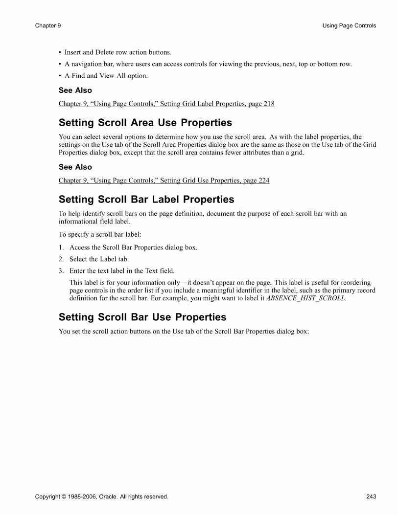
Chapter 9 Using Page Controls
• Insert and Delete row action buttons.• A navigation bar, where users can access controls for viewing the previous, next, top or bottom row.• A Find and View All option.
See AlsoChapter 9, “Using Page Controls,” Setting Grid Label Properties, page 218
Setting Scroll Area Use PropertiesYou can select several options to determine how you use the scroll area. As with the label properties, thesettings on the Use tab of the Scroll Area Properties dialog box are the same as those on the Use tab of the GridProperties dialog box, except that the scroll area contains fewer attributes than a grid.
See AlsoChapter 9, “Using Page Controls,” Setting Grid Use Properties, page 224
Setting Scroll Bar Label PropertiesTo help identify scroll bars on the page definition, document the purpose of each scroll bar with aninformational field label.
To specify a scroll bar label:
1. Access the Scroll Bar Properties dialog box.2. Select the Label tab.3. Enter the text label in the Text field.This label is for your information only—it doesn’t appear on the page. This label is useful for reorderingpage controls in the order list if you include a meaningful identifier in the label, such as the primary recorddefinition for the scroll bar. For example, you might want to label it ABSENCE_HIST_SCROLL.
Setting Scroll Bar Use PropertiesYou set the scroll action buttons on the Use tab of the Scroll Bar Properties dialog box:
Copyright © 1988-2006, Oracle. All rights reserved. 243

Using Page Controls Chapter 9
Specifying scroll bar Use
Access the Scroll Bar Properties dialog box. Select the Use tab.
Scroll Attributes
Occurs Level Having an occurs level for the scroll bar enables you to designate thehierarchical parent and child relationship. Entering 1 specifies that the scrollbar is at the first level. Entering 2 specifies that a scroll is at the second leveland is a child of, or nested in, the first level of data, and so on up to 3. A scrollcan be nested in another scroll or scroll area, but it cannot be nested in a grid.
See Chapter 10, “Creating Page Definitions,” Level-Based Controls, page 252.
Occurs Count Enter the number of rows to appear at one time in the grid at runtime.
See Chapter 10, “Creating Page Definitions,” Level-Based Controls, page 252.
Note. Always reorder your controls, if necessary, before you enter anoccurs count.
Field Use Options
Invisible Select to make the scroll bar invisible.
Default Width This does not apply because the scroll bar does not appear on the page atruntime.
244 Copyright © 1988-2006, Oracle. All rights reserved.

Chapter 9 Using Page Controls
No Auto Select Select to prevent the system from retrieving data automatically from thedatabase. Select to populate the scroll bar with data using the ScrollSelectPeopleCode functions.
No Auto Update Select to prevent the system from updating data automatically based on theexisting key list. Select when the scroll bar contains work field controls thatshould affect only a page and not the underlying database.
No Row Insert Select to prevent the row insert function so that the user cannot insert new rows.
No Row Delete Select to prevent the delete function so that the user cannot delete rows.
Scroll Action ButtonsIf you select a Scroll Action Button option, it appears on the page next to the scroll bar in PeopleSoftApplication Designer. You must manually move it to the appropriate location on the page definition.
Previous Page Select to display a link that enables the user to move to the previous rowor set of rows in the scroll buffer.
Row Insert Select to display a button that enables the user to add a row.
Top Select to display a link that enables the user to go to the first row of the scroll.
Show Row Counter Select to display a counter to show users what rows they are viewing and thetotal number of rows in the scroll bar, for example: <1 of 3>.
Next Page Select to display a link that enables the user to move to the next row or set ofrows in the scroll buffer.
Row Delete Select to display a button that enables the user to delete a row.
Bottom Select to display a link that enables the user to go to the last row of thescroll bar.
When working with the row counter when designing pages in PeopleSoft Application Designer (not at runtimein a browser), consider the following:
• If the header area navigation bar is set to invisible, the system displays no header area navigation bar rowcounter button. Likewise, if the footer area navigation bar is set to invisible, the system displays no footerarea navigation bar row counter button. If the row counter button of the header area navigation bar is set toinvisible, the system displays no header area navigation bar row counter button.
• If the row counter button of the footer area navigation bar is set to invisible, no footer area navigation barrow counter button is displayed. Otherwise, if not set to invisible, the row counter button will be displayedas "|<< your_label >>|" where your_label is the specified text.
• If the text of the label is an empty string or the label refers to the message catalog with a message set of 0and a message number of 0, then "your label" appears as an empty string and the label will be rendered as"|<< >>|".
Controlling Scrollable DataYou can control scrollable data using the PeopleCode Data Buffer Access Classes.
See Enterprise PeopleTools 8.48 PeopleBook: PeopleCode Developer’s Guide, “Accessing the Data Buffer”.
Copyright © 1988-2006, Oracle. All rights reserved. 245

Using Page Controls Chapter 9
Converting Scroll Bars to GridsYou can convert a single-level scroll bar to a grid control. PeopleSoft Application Designer provides a utilityto automate this task. The Convert Scroll to Grid function:
• Designates the size and position of the grid as set to the area covered by the left-most label to the scroll bar.• Issues warnings before deleting controls that are not supported by the grid.• Converts radio buttons to drop-down list boxes.• Sets label alignment of check boxes to center.
The conversion utility provides warnings for scroll bars that can’t be converted to grids due to grid controllimitations. The conversion utility validates to the following limitations:
• No more than one grid can exist on a page.
• The scroll bar to be converted must not have any nested scroll areas or bars under it.
• The grid control must be the last control on the page.
• Radio buttons are not supported in grids and must be replaced with drop-down list boxes.
To convert a scroll to a grid:
1. Select the scroll bar.2. Right-click and select Convert Scroll To Grid from the pop-up menu.This menu option is available only for scroll bars that can be converted. This utility searches for all pagefields that are defined in the field order after the selected scroll bar control, up until the next scroll bar orscroll area control. It does the following for each field:• Confirms that the scroll control type can be displayed in a grid control.• Creates a grid column of the appropriate type.• Populates in the attributes.
3. Click OK to display the new grid.
If any of the page fields cannot be displayed in a grid or if other problems are found, the utility displays anerror message explaining why the scroll bar cannot be converted to a grid. If no problems are found, the GridProperties dialog box appears, listing all of the fields that will be converted to columns. You can changeany grid or field properties at this time.
Using Secondary PagesThis section provides an overview of secondary pages and discusses how to:
• Define secondary pages.• Insert a secondary page control.
Understanding Secondary PagesWhile a secondary page is just another page to the user at runtime, they look and behave differently than theprimary pages. For example:
246 Copyright © 1988-2006, Oracle. All rights reserved.

Chapter 9 Using Page Controls
• You can view a secondary page from its primary page only.• A secondary page should have OK and Cancel buttons so that the user can dismiss the page (accepting orcanceling input) and return to the primary page.To offer the user alternative buttons to dismiss the page, disable the default OK and Cancel buttons in thePage Properties dialog box.
Secondary Page or a Push Button?There are two ways to associate a secondary page with a primary page:
• Insert a push button or link and associate it with your secondary page.This automatically displays the secondary page when the user presses the button or clicks the link andis the preferred method. Use this method when:- No procedural PeopleCode logic is necessary before the secondary page is displayed (PeopleCode can beused on the secondary page just like any other page).
- You want to control the formatting of the information (therefore you want to use a page, and not usethe Prompt function).
- The secondary page is used more than once.• Insert a secondary page control.This control looks like a command push button, but it is invisible at runtime. When you use a secondarypage control, you must also insert a command push button on the page and call the DoModal PeopleCodefunction from the FieldChange event for the push button to display the secondary page.
ExampleIn the following example, the Address page contains an Email link at the bottom of the scroll area. This linkopens the Email Addresses page, enabling the user to enter email address information.
Primary page
Copyright © 1988-2006, Oracle. All rights reserved. 247

Using Page Controls Chapter 9
Secondary page
After the user enters the email information in the Email grid, the user can return to the Address page byclicking OK.
Defining Secondary PagesDetermine which data in the primary component is appropriate for a secondary page. Typically, this issupplemental information or information that is accessed from more than one main page.
Page Properties dialog box
248 Copyright © 1988-2006, Oracle. All rights reserved.

Chapter 9 Using Page Controls
To create a secondary page:
1. Select File, New and select Page from the New Definition dialog box.
2. Open the Page Properties dialog box.
3. Select the Use tab.
4. Select Secondary Page from the drop-down list box in the Page Type group box.
5. Select the page size:
Auto-Size Select to size the page automatically to fit the fields that are defined on it.
Custom Size Select to size the secondary page by dragging the edge or by enteringthe width and height in pixels.
6. Select the page style sheet to associate with the secondary page.To override the default style sheet that is associated with the application, select a different style sheetfrom the drop-down list box. The style sheet that you select is available only for the controls on thesecondary page.
7. Select the page background.You can control the background of the page and any controls that don’t have a style sheet associated withthem by specifying a style in the page background.
8. (Optional) Select Adjust Layout for Hidden Fields.9. (Optional) Clear Allow Deferred Processing if you want processing to occur each time the user pressesTAB to move through a field.
10. Click OK and save your secondary page.If you selected Auto-Size, the system sizes the page automatically to fit the fields that are defined on itwhen you save.
Inserting a Secondary Page ControlAfter you define the secondary page, you can place a secondary page control on your primary page andassociate it with the secondary page you just created.
To insert a secondary page control on a primary page:
1. Select Insert, Secondary Page.
2. Click the primary page where you want to display the secondary page control.
The secondary page control appears like a small push button with the secondary page icon on it. Thiscontrol is invisible at runtime.
3. Double-click the control to access the Secondary Page Properties dialog box: Secondary Page tab.
4. Select the name of the secondary page to associate with the secondary page control on the active page.
Only secondary pages can be associated with secondary page controls. You cannot associate a standardpage or subpage with the secondary page control.
5. Select the Label tab.
This label is for informational purposes only. It appears in the Order tab of the page definition and inthe page description printout.
6. Position the secondary page control at the proper scroll level on the Order tab.
Copyright © 1988-2006, Oracle. All rights reserved. 249

Using Page Controls Chapter 9
See Chapter 9, “Using Page Controls,” Specifying Destination Types, page 232.
250 Copyright © 1988-2006, Oracle. All rights reserved.

CHAPTER 10
Creating Page Definitions
Pages are the graphical interface between your users and your application database. As a system designer, youconfigure or build pages that meet the data requirements of the application and that are easy to use and understand.Using PeopleSoft Application Designer, you can create, modify, and delete page definitions in your PeopleSoft system.
This chapter provides an overview of page design and development and discusses how to:
• Use page development tools.• Create new page definitions.• Add page controls.• Manipulate page controls.• Set page field properties for controls.• Create display control and related fields.• Order and space page controls.• Design inquiry pages.• Align page controls.• Maximize performance.• Access PeopleCode in page definitions.• View pages in the browser.• Produce pages.• Work with pages in foreign languages.
Understanding Page DesignThis section discusses:
• Level-based controls.• Keys for accessing pages.• Multiple occurrences of data.• Prompt fields.• Derived work fields.• Sensitive data.• Hidden pages.
Copyright © 1988-2006, Oracle. All rights reserved. 251

Creating Page Definitions Chapter 10
• Upgrade considerations.• End user page customization.
Level-Based ControlsPage design hinges on the type of data that you plan to access and maintain. In some cases, a page references asingle record definition; in others, you may want to reference multiple records. To accommodate a variety ofpage designs, PeopleSoft created level-based controls. The three level-based controls are:
• Grids• Scroll areas• Scroll bars
There are four levels in level-based controls: Level 0, Level 1, Level 2, and Level 3. These levels are referencedas occurs levels on the Record tab in the page field properties for the level-based control that you are setting.
• Level 0This is the nonscrolling area that directly relates to the key information of the underlying record. Level 0information is usually display-only with data that the user entered on the initial search page.
• Levels 1−3These levels include the scrolling data that is related to the Level 0, nonscrolling data. Level 1 is subordinateto Level 0; Level 2 is subordinate to and nested in Level 1; and Level 3 is subordinate to and nested in Level2. You can nest level-based controls up to 3 levels.
The first occurs level on a page is Level 0. In general, this level is reserved for the primary key fields that areused to search for pages. It is possible to have a page that contains no level-based controls, making all fields setto Level 0. This is particularly true for secondary or subpages that contain few data entry fields, as shown in thisexample. The second column, Lvl (level), of the Order tab indicates that all fields on the page are at Level 0.
Order tab
After you add a level-based control to your page, such as a scroll area, the default occurs level for that controlis set to one in the properties dialog box. If you place a field in or below that scroll area, it is also set to Level 1in the Order tab, even if it is another level-based control. If necessary, you can use the Set to Level 0 featureof the horizontal rule control to restart the occurs level on your page.
Note that you can have any number of level-based controls at the same level.
252 Copyright © 1988-2006, Oracle. All rights reserved.

Chapter 10 Creating Page Definitions
Nested Level-Based ControlsNesting controls involves two or more level-based controls on a page, such as two scroll areas, when thesecond scroll area has an occurs level of 2. You nest controls when the new data that you want to add is arepeating set of data for each entry in your first level-based control. In doing so, you create a hierarchical, or"parent and child" relationship between the controls and the processing of the record definitions. The Level 2control is the child of, and is subordinate to, the Level 1 control.
For example, on the Compensation page, the Level 2 grid is nested in the Level 1 scroll area. On the Amountstab of the grid, there are two rate codes for each compensation action in the Level 1 scroll area.
Compensation page
You can nest up to three levels of scrolls or grids on your page. For example, the Additional Pay 1 page showsthree levels of data that can be entered, two of which are nesting scroll areas in the Earnings scroll area.
Copyright © 1988-2006, Oracle. All rights reserved. 253

Creating Page Definitions Chapter 10
Additional Pay 1 page
In this case, we want to maintain information about the compensation history for a single employee, and, foreach change or override in compensation status, enter the details about that change. The first scroll area,Earnings, associates the earning code with the second, subordinate scroll area, Eff Date (effective date) andDefault Job Data, which enables the user to enter the effective date for the status change. The third scroll area,Or Overrides to Job Data, which is subordinate to the second, enables the user to enter the overrides to thedefault job data that appears in the second scroll area.
For each of the three scroll areas, you can have several rows of data. While you don’t see actual scrollbars on your page, the navigation buttons and links in the navigation bars for each scroll area enable youto navigate or scroll through the rows.
Nested Grids in ScrollsAs shown previously, you can nest a grid in a scroll or scroll area. The following page shows the OtherEarnings grid at Level 3, which is nested in the Earnings scroll area at Level 2, which is nested in the PaysheetDetails scroll area at Level 1. A nested grid serves the same function as a nested scroll area. It can offer a morecompact way of viewing many fields of data, particularly if you use a tabbed grid.
Note. While you can nest a grid in a scroll area, you cannot nest a scroll area in a grid or a grid in another grid.
254 Copyright © 1988-2006, Oracle. All rights reserved.

Chapter 10 Creating Page Definitions
Paysheet page
Levels and Runtime ProcessingLevels play an important role in runtime processing. The component processor relies on the level at which youplace a field on a page to determine how to process any PeopleCode attached to the field in the record definition.
Effective Dates and Level-Based ControlsEFFDT (effective date) must be the only key field that is controlled by level-based controls that you create tohelp users maintain multiple occurrences of data that is keyed by effective date. Otherwise, the effective dateprocessing for update actions does not function correctly.
See AlsoEnterprise PeopleTools 8.48 PeopleBook: PeopleCode Developer’s Guide, “Referencing Data in theComponent Buffer”
Keys for Accessing PagesNo matter how much time and effort you invest in defining and refining your page, it’s useless unless the usercan access it. This means adding it to a component, then adding that component to a menu. When you adda page to a component, you determine what actions the user must perform to access the page and the keysthat are required to retrieve rows of information.
The search record that you define for a component determines the key list; that is, keys for which users areprompted when they select a page and an action. A search record can be either a view that concatenatesinformation stored in several tables or the underlying table itself. Select the search record that contains all ofthe key items for the primary record underlying the page.
Copyright © 1988-2006, Oracle. All rights reserved. 255
Creating Page Definitions Chapter 10
The keys for which the search dialog box prompts should populate the high-level (Level 0 in the pagedefinition) key controls on a page. These key controls always appear above any level-based control on thepage and are typically display-only. A search record might differ from a primary record definition, but it mustcontain all of the Level 0 keys that you have placed on the page.
Using Keys for ViewsWhen you create a view that should use key values from a page, each of those keys must be:
• Listed as output columns from the view (not just referenced in the WHERE clause of the view).• Marked as key fields of the view.
For example, suppose that a page has PERSON.PERSONID as a Level 0 field. PERSONID is the key of thePERSON record. A grid on the page uses the PERSON_ADDRESS_VW view to display addresses for thecurrent person. The SQL statement for the view cannot just mention PERSON.PERSONID in the WHEREclause; PERSONID must be both an output column of the view and a key field of the view.
See AlsoChapter 6, “Creating Record Definitions,” page 107
Chapter 11, “Creating Component Definitions,” page 309
Multiple Occurrences of DataOn some pages, you may want a few of the field controls to display multiple rows or occurrences of data.To do this, you can add a level-based control—a scroll area, a grid, or a scroll bar. Users can then add, edit,delete, find, and scroll through multiple occurrences of data in a page control or group of controls using actionbuttons, links, or the browser’s scroll bar, depending on how you set the occurs count. Using a scroll area or agrid, rather than a scroll bar, is the preferred page design to show multiple occurrences of data.
For example, this Checklist Table page contains the Assignment Checklist Item grid with an occurs countof 5. The Checklist Item scroll area in which it is nested must have an occurs count of 1 since we can seeonly one row of data in the scroll area.
256 Copyright © 1988-2006, Oracle. All rights reserved.

Chapter 10 Creating Page Definitions
Checklist Table page
To see the next set of five rows in the Assignment Checklist Item grid, a user can click the right arrow button.To see all rows of data at once, in either the grid or scroll area, the user can select the View All link in thenavigation bar.
In PeopleSoft Application Designer, you set the occurs count for a level-based control on the General tab inthe properties dialog box. You can set the occurs count to any number. You also have the option of selectingUnlimited Occurs Count so that the user sees all rows of data. If there are more options than can be seen in thewindow at runtime, the browser displays a scroll bar enabling the user to scroll to the bottom of the page.
Note. When occurs count is set to a number other than 1, the grid displays the specified number of rows.However, when it is set to 1, the grid displays as many rows as possible within the given space allocated forthe grid control at design time.
Prompt FieldsAt runtime, you may want to enable your users to look up the valid values that they can enter in a field. Forthis, PeopleSoft provides prompts or look up buttons. There are three types of prompts:
• Drop-down list box.This is a small list that opens below a field in the current page, such as the Job Indicator field on the WorkLocation page. To use a drop-down list box, the user clicks the down arrow inside the field. One does nothave to exit the page. The drop-down list box is a predefined control that you place on your page.
• Calendar drop-down prompt.A calendar drop-down prompt opens a small calendar next to a date field to enable the user to easily scanfor the correct date. The Work Location page contains calendar prompts for the Effective Date, PositionEntry Date, and Department Entry Date fields. Place a calendar prompt on a page by associating any datefield with an edit box control and selecting the Show Prompt Button in the Display Options of the Recordproperties of the edit box.
Copyright © 1988-2006, Oracle. All rights reserved. 257
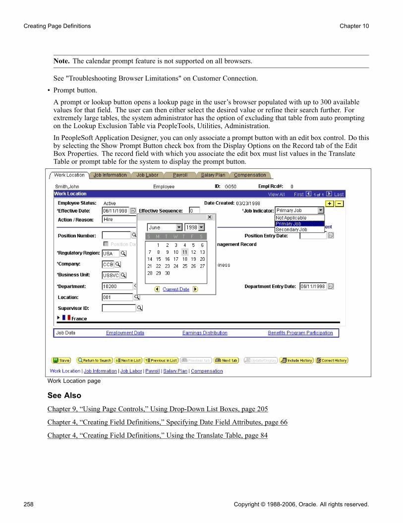
Creating Page Definitions Chapter 10
Note. The calendar prompt feature is not supported on all browsers.
See "Troubleshooting Browser Limitations" on Customer Connection.• Prompt button.A prompt or lookup button opens a lookup page in the user’s browser populated with up to 300 availablevalues for that field. The user can then either select the desired value or refine their search further. Forextremely large tables, the system administrator has the option of excluding that table from auto promptingon the Lookup Exclusion Table via PeopleTools, Utilities, Administration.In PeopleSoft Application Designer, you can only associate a prompt button with an edit box control. Do thisby selecting the Show Prompt Button check box from the Display Options on the Record tab of the EditBox Properties. The record field with which you associate the edit box must list values in the TranslateTable or prompt table for the system to display the prompt button.
Work Location page
See AlsoChapter 9, “Using Page Controls,” Using Drop-Down List Boxes, page 205
Chapter 4, “Creating Field Definitions,” Specifying Date Field Attributes, page 66
Chapter 4, “Creating Field Definitions,” Using the Translate Table, page 84
258 Copyright © 1988-2006, Oracle. All rights reserved.

Chapter 10 Creating Page Definitions
Derived and Work FieldsYou can use a field definition from a derived or work record to store a temporary value that PeopleCode uses todetermine the values of other field controls on the page.
For example, for a budgeting transaction in PeopleSoft General Ledger, assume that you have an annualamount that you must spread to multiple accounting periods. You can create a page that includes both a fieldcontrol from a derived record for the annual amount and an amount control for each accounting period. Youthen write PeopleCode to derive the amount per accounting period from the annual amount. When a userenters the annual amount in the derived field control, PeopleCode calculates the amount per accounting periodand inserts it into each accounting period field control. The annual amount isn’t stored in the database, butthe period amounts are.
Sensitive DataYou can allocate sensitive data to a single page and limit access to that page to the users who need to updateit. Alternatively, you can enter PeopleCode to hide certain fields on pages based on whatever criteria areappropriate. The page approach is simpler, however, and can be used in most situations. For secondary pages,this sort of security is more complex to manage.
See AlsoEnterprise PeopleTools 8.48 PeopleBook: PeopleCode Language Reference, “PeopleCode Built-in Functions,”Hide
Hidden PagesHidden pages are work pages that are associated with derived or work records and are often used in workgroups. You can store all of your work field controls there. Create these pages when you want calculations tobe performed in the background by PeopleCode that the user does not need to see. As a convention, PeopleSoftassigns work pages that are delivered with your application names that end with the suffix, _WRK. PeopleSoftrecommends that you follow the same naming convention. For example, MC_TYPE_WRK.
Hide a page by selecting the Hidden check box in the component grid as you set up the component definition.
See AlsoChapter 11, “Creating Component Definitions,” Setting Page Attributes, page 315
Upgrade ConsiderationsIf you adapt a PeopleSoft application, you might affect your use of future PeopleSoft releases. The closer yourPeopleSoft system is to the standard product, the easier your upgrades will be. Avoid superfluous or cosmeticchanges to data structures in the standard product. Document all of your changes in the comment area onthe General tab in the Page Properties dialog box.
End User Page CustomizationEnd users of PeopleSoft applications can customize various settings on a page including tab order, the displaystate of scroll areas and grids, and the state of collapsible sections. Users can also choose the default page todisplay for a component each time they open that component. In addition, users can choose to share theircustomization settings with or copy settings from another user.
Copyright © 1988-2006, Oracle. All rights reserved. 259

Creating Page Definitions Chapter 10
The page customization option is set in the Component Properties dialog box, Internet tab. The CustomizePage Link check box is selected by default. This enables the Customize Page link in the pagebar at runtimefor all pages.
See AlsoChapter 11, “Creating Component Definitions,” Setting Internet Properties, page 321
Enterprise PeopleTools 8.48 PeopleBook: Using PeopleSoft Applications, “Setting User Preferences,”Customizing Pages
Using Page Development ToolsThis section discusses how to:
• Use page definition menus.
• Use page definition toolbars.
• Use the page layout grid.
Using Page Definition MenusAs you build pages, use the tools and options in these menus.
• File Menu.In addition to the standard options for opening, deleting, and renaming pages, use this menu to access thedefinition (page) properties and project properties.
• Edit Menu.Access the page field properties from this menu. To find out what other definitions reference the activepage, select Find Definition References. You can also search for a text string in types of PeopleCodeor SQL objects.
• View Menu.- Select View Definition to view the underlying definition, such as the subpage or record, for the selectedcontrol.You can view the PeopleCode for the page or the underlying record definition.
- Edit Fill Display, Edit Fill All, and Edit Fill None refer to how controls appear only during design time.They do not affect the page during runtime.
- Use the Show Page Control Inspector tool to view summary data of the selected page field.- Use Show Grid to display or hide a layout grid on the page that you are designing to help you placecontrols more accurately.
• Insert Menu.Use this menu to insert different types of controls on your page. You can also insert the page on whichyou are working into a project.
• Tools Menu.
260 Copyright © 1988-2006, Oracle. All rights reserved.
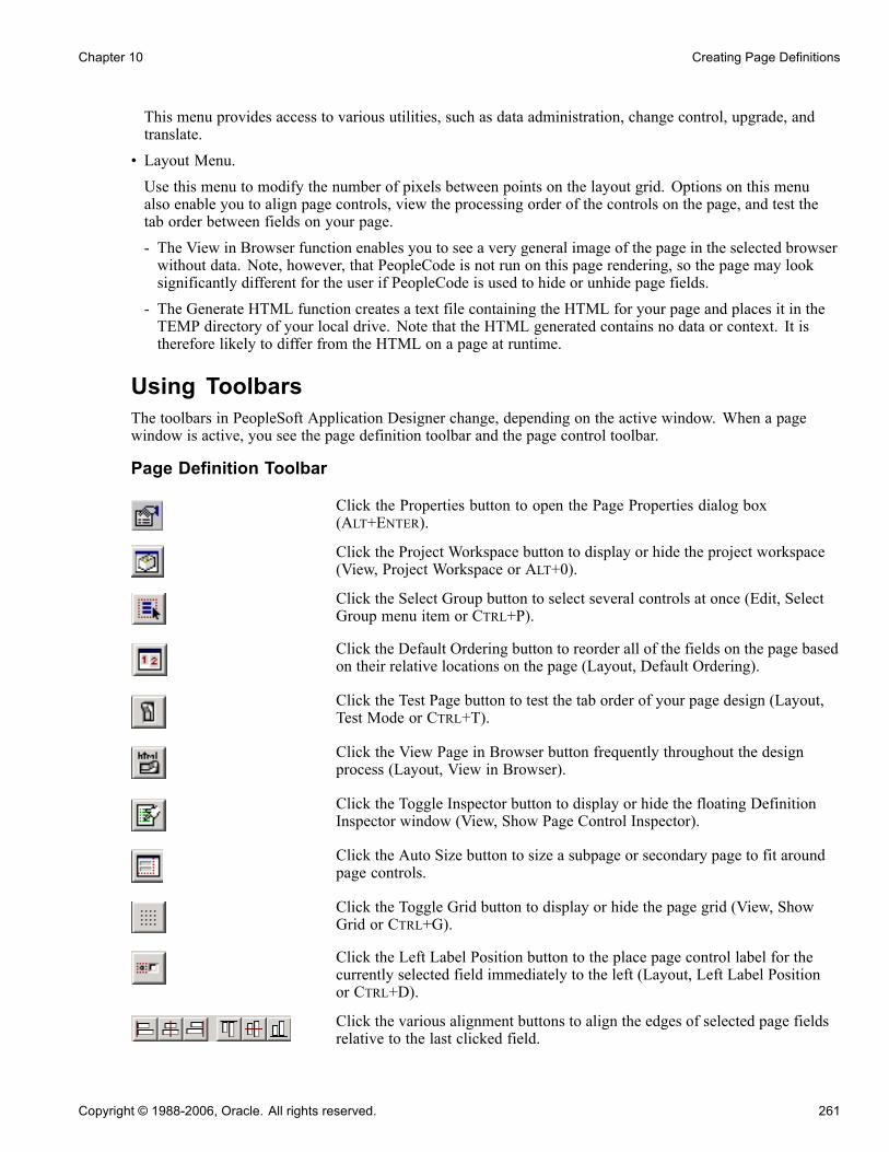
Chapter 10 Creating Page Definitions
This menu provides access to various utilities, such as data administration, change control, upgrade, andtranslate.
• Layout Menu.Use this menu to modify the number of pixels between points on the layout grid. Options on this menualso enable you to align page controls, view the processing order of the controls on the page, and test thetab order between fields on your page.- The View in Browser function enables you to see a very general image of the page in the selected browserwithout data. Note, however, that PeopleCode is not run on this page rendering, so the page may looksignificantly different for the user if PeopleCode is used to hide or unhide page fields.
- The Generate HTML function creates a text file containing the HTML for your page and places it in theTEMP directory of your local drive. Note that the HTML generated contains no data or context. It istherefore likely to differ from the HTML on a page at runtime.
Using ToolbarsThe toolbars in PeopleSoft Application Designer change, depending on the active window. When a pagewindow is active, you see the page definition toolbar and the page control toolbar.
Page Definition Toolbar
Click the Properties button to open the Page Properties dialog box(ALT+ENTER).
Click the Project Workspace button to display or hide the project workspace(View, Project Workspace or ALT+0).
Click the Select Group button to select several controls at once (Edit, SelectGroup menu item or CTRL+P).
Click the Default Ordering button to reorder all of the fields on the page basedon their relative locations on the page (Layout, Default Ordering).
Click the Test Page button to test the tab order of your page design (Layout,Test Mode or CTRL+T).
Click the View Page in Browser button frequently throughout the designprocess (Layout, View in Browser).
Click the Toggle Inspector button to display or hide the floating DefinitionInspector window (View, Show Page Control Inspector).
Click the Auto Size button to size a subpage or secondary page to fit aroundpage controls.
Click the Toggle Grid button to display or hide the page grid (View, ShowGrid or CTRL+G).
Click the Left Label Position button to the place page control label for thecurrently selected field immediately to the left (Layout, Left Label Positionor CTRL+D).
Click the various alignment buttons to align the edges of selected page fieldsrelative to the last clicked field.
Copyright © 1988-2006, Oracle. All rights reserved. 261

Creating Page Definitions Chapter 10
See Chapter 10, “Creating Page Definitions,” Aligning Page Controls, page292.
Click the Show Help button to view the page definition help.
Page Control ToolbarThe page control toolbar contains a button for each type of page control that you insert. The buttons displayimages that look like the controls that they insert. You can move this toolbar on your workspace independentlyof the system toolbar or the other half of the page definition toolbar.
Frame.
Group box.
Horizontal rule.
Static text.
Static image.
Grid tab separator.
Check box.
Drop-down list box.
Edit box.
HTML area.
Image.
Long edit box.
Push button/hyperlink.
Radio button.
262 Copyright © 1988-2006, Oracle. All rights reserved.

Chapter 10 Creating Page Definitions
Tree.
Grid.
Scroll area.
Scroll bar.
Secondary page.
Subpage.
Chart.
Using the Page Layout GridWhen you open a page definition, evenly spaced dots appear in the workspace. This is the page layoutgrid that you use to align controls. When you’re running applications, the grid doesn’t appear on pages. Itappears only as a design aid in the page definition.
Layout grid
The default grid spacing is 4 × 4, which means that each row has one dot per 4 pixels and that the rows are 4pixels apart on the vertical axis. PeopleSoft builds most of the pages in the standard applications using thisgrid. To change the spacing, open the Layout Grid dialog box by selecting Grid Settings from the Layout menu.
You can turn off the grid view of your page by clicking the Toggle Grid button in the page definition toolbar.
Changing Page Layout Grid SettingsTo change the grid spacing:
1. Select Layout , Grid Settings.
2. Enter values for the width and the height, which is the spacing of the dots in pixels.
Copyright © 1988-2006, Oracle. All rights reserved. 263

Creating Page Definitions Chapter 10
The smaller the value, the finer the grid. The finer the grid, the more difficult it is to align fields preciselywithout using the align functionality. Note that if either the width or height are set to one, then the grid willbe slightly off.Select a Show Grid option to activate or deactivate the page grid.If you copy an existing page and save it under another name, you also copy the grid settings that wereused to create the original page. For example, if the original page was built with a 5 × 5 grid, your newpage also has a 5 × 5 grid, by default. You can change the grid settings anytime while working on a page.Doing so has no effect on the position of a field.The snap-to-grid functionality is only available when the layout grid is showing.
Creating New Page DefinitionsTo create a new page definition, either clone an existing page or begin with a blank page. Cloning is moreefficient, because you don’t have to re-create controls that are common to all pages. You can also create atemplate that contains only the controls that you need.
This section discusses how to:
• Clone page definitions.• Create a blank page.
Note. When saving new definitions, always make sure to adhere to accepted naming conventions.
See Chapter 2, “Using PeopleSoft Application Designer,” Saving Definitions, page 29.
Cloning Page DefinitionsTo clone a page definition:
1. Select File, Open.The Open Definition dialog box appears.
2. Specify Page for the definition and locate the page that you want to clone.3. When the system retrieves the page definition, select File, Save As.If you save after you make modifications, you might accidentally overwrite the old page definition.
4. Enter the new page name.To create a new page template, name the page so that it appears at the top of your page list.
5. Click OK.
Note. Record definition names are restricted to a maximum of 15 characters, while page names can have upto 18 characters.
See AlsoChapter 2, “Using PeopleSoft Application Designer,” Opening Definitions, page 26
Chapter 2, “Using PeopleSoft Application Designer,” Saving Definitions, page 29
264 Copyright © 1988-2006, Oracle. All rights reserved.
Chapter 10 Creating Page Definitions
Creating a Blank PageTo create a new page without copying an existing page, select File, New, Page.
When saving the page, make sure that you adhere to the accepted naming conventions.
See Chapter 2, “Using PeopleSoft Application Designer,” Saving Definitions, page 29.
Adding Page ControlsThere are multiple ways to add page fields to a page. You can copy page fields from one page and paste themonto another, or you can drag-and-drop page fields from one page to another. In addition to these basicmethods, this section discusses how to:
• Drag field definitions from a record onto a page.
• Drag record fields from the project workspace onto a page.
• Drag record definitions onto a page.
• Use the page control toolbar.
• Use the Insert menu.
Dragging Field Definitions From a Record Onto a PageTo drag field definitions from a record onto a page:
1. Open an existing record definition by selecting File, Open, Record.2. Open a new page by selecting File, New, Page.3. Drag field definitions from the record to the page.The system selects the page definition control type based on the record field attributes. In the precedingpage, the EMPLID (employee identification) field was defined as a prompt table edit in the record, so aPrompt button was added for EmplID when it was dragged onto the page.
4. Double-click the new page field to set the properties.When you drag field definitions, the properties from the record definition are used to set page field defaultproperties. You can alter the properties using the Properties dialog box.
Dragging Record Fields From the ProjectWorkspace Onto a PageTo drag record fields from the project workspace onto a page:
1. Open the project that you want to drag from an existing or new page.2. Drag record fields from the project workspace to the page.3. Double-click the new page field to set the properties.
Note. When you drag fields from the project workspace, use fields that are contained in records (as inrecord.fieldname), not field definitions.
Copyright © 1988-2006, Oracle. All rights reserved. 265
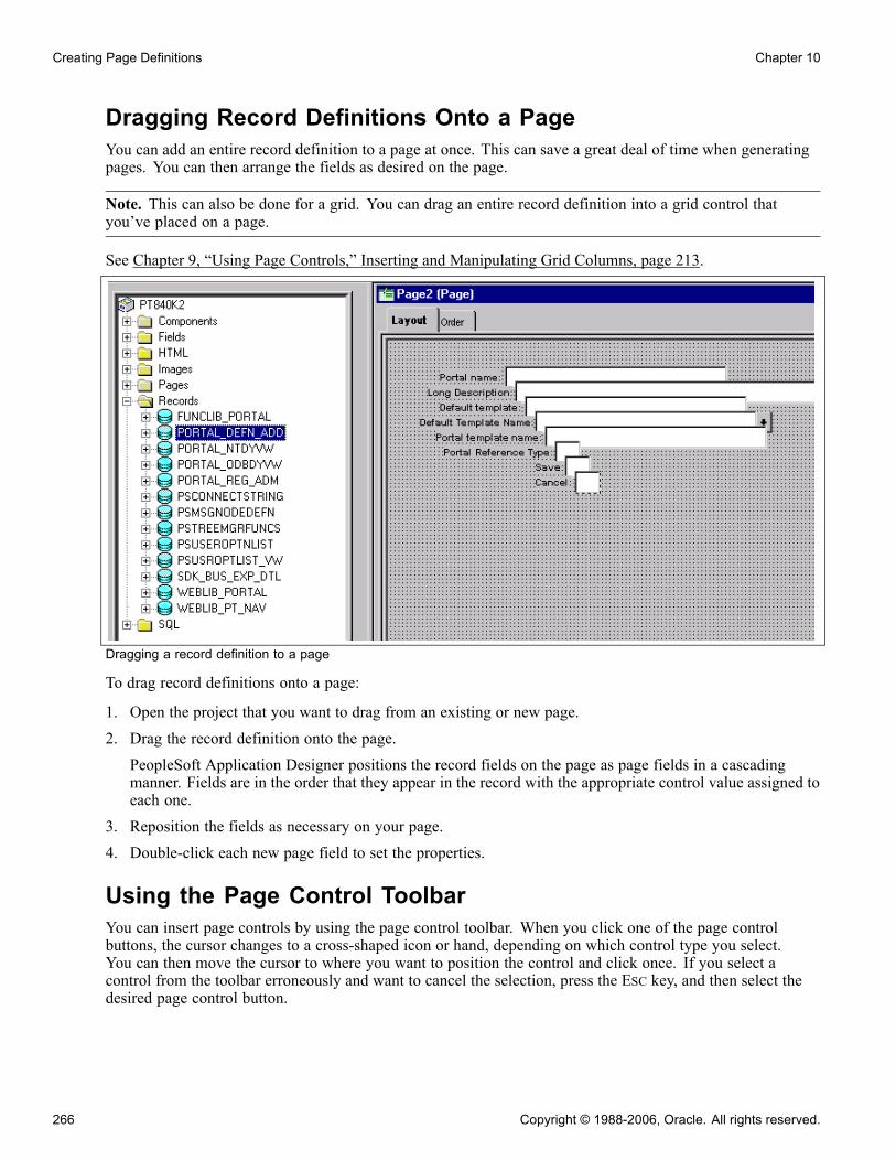
Creating Page Definitions Chapter 10
Dragging Record Definitions Onto a PageYou can add an entire record definition to a page at once. This can save a great deal of time when generatingpages. You can then arrange the fields as desired on the page.
Note. This can also be done for a grid. You can drag an entire record definition into a grid control thatyou’ve placed on a page.
See Chapter 9, “Using Page Controls,” Inserting and Manipulating Grid Columns, page 213.
Dragging a record definition to a page
To drag record definitions onto a page:
1. Open the project that you want to drag from an existing or new page.2. Drag the record definition onto the page.PeopleSoft Application Designer positions the record fields on the page as page fields in a cascadingmanner. Fields are in the order that they appear in the record with the appropriate control value assigned toeach one.
3. Reposition the fields as necessary on your page.4. Double-click each new page field to set the properties.
Using the Page Control ToolbarYou can insert page controls by using the page control toolbar. When you click one of the page controlbuttons, the cursor changes to a cross-shaped icon or hand, depending on which control type you select.You can then move the cursor to where you want to position the control and click once. If you select acontrol from the toolbar erroneously and want to cancel the selection, press the ESC key, and then select thedesired page control button.
266 Copyright © 1988-2006, Oracle. All rights reserved.

Chapter 10 Creating Page Definitions
If the control is a fixed size during insertion, the cursor changes to a cross-shaped icon. If the control typerequires that you define the size of the control at the time of insertion, the cursor changes to the monogrammedhand icon. When a hand-shaped icon appears, press and hold the left mouse button as you drag the handdiagonally downward to where you want the lower, right-hand corner of the frame. Release the mouse button.
If the control isn’t correct the first time that you draw it, you can easily adjust it. The dotted box and black orblue handles surrounding the control indicate that it is selected. Use any of the four directional arrow keyson the keyboard to move the frame one page grid unit in the indicated direction. You can also use SHIFT+the arrow key to resize the page control.
Using the Insert MenuSelect the control that you want to add to your page from the Insert menu. Your cursor changes to across-shaped icon or a hand, depending on which control type you select. Move the cursor to where you wantto position the control and click once.
Manipulating Page ControlsAfter you place a control on the page, you have several choices for manipulating it.
This section discusses how to:
• Select controls.• Resize controls.• Use the Page Control Inspector.• Delete controls.• Move controls on the same page.• Copy and move controls to another page.• Move labels.
Selecting ControlsBefore you do anything to a control, you must select it. You can do this by clicking the control or by using theEdit menu. A check mark beside the option in the menu indicates which of these modes you’re in:
Select Field Select one control on the page by clicking on it. To deselect a control, clickonce outside the dotted box. This is the default mode.
Select Group Select a group of controls by drawing a box around the controls that youwant to select. You can also activate this option by clicking and draggingover the target fields.
Note. You are in Select Group mode when the cursor changes to a pointingfinger. If the cursor does not change when you select Edit, Select Group, tryfirst selecting an individual control on the page and then selecting Edit,Select Group again.
Copyright © 1988-2006, Oracle. All rights reserved. 267

Creating Page Definitions Chapter 10
Select All Select all of the controls on the active page. The result is the same as using theSelect Group option to draw a box around the controls.
Resizing ControlsYou can adjust the size or shape of any page control that displays selection handles when it is selected.
Resizing a control with selection handles
Note. Some browsers do not support the resizing of certain control types. In these cases, changing the size inPeopleSoft Application Designer has no effect upon the runtime size of the field.
See "Troubleshooting Browser Limitations" on Customer Connection.
To resize a control, use one of these methods:
• Select the control and drag a handle to adjust the height or width.
Note. Some control types can be adjusted only in width.
• Hold down the SHIFT key while pressing the UP ARROW, DOWN ARROW, LEFT ARROW, or RIGHT ARROWkey.The frame size is adjusted one grid unit in the indicated direction.
Note. The position of the top, left-hand corner of the frame does not change; resizing with the keyboard occursby adjusting the position of the bottom, right-hand corner.
Using the Page Control InspectorThe Page Control Inspector provides location, size, type, and data source information for the selected pagecontrol on the page. The first six values, Left, Width, Right, Top, Height, and Bottom, display the exactbounding coordinates in pixels of the control on your page in PeopleSoft Application Designer. The remainingvalues help distinguish the selected control from others on the page.
Access the Page Control Inspector from the View menu or by clicking the Toggle Inspector button on the pagedefinition toolbar. When you finish viewing the values for one control, simply click another control to view itsvalues. This enables you to check multiple controls on the page in quick succession.
268 Copyright © 1988-2006, Oracle. All rights reserved.

Chapter 10 Creating Page Definitions
Page Control Inspector
Note. The HTML that is generated for your page uses table layout, rather than pixel layout. It is important topreview how your page might look in the PeopleSoft Pure Internet Architecture as you design it. Spacing offields at runtime may not appear exactly the same as during design time.
While the Page Control Inspector displays values for a grid, no information is available for individual gridcolumns.
Deleting ControlsIf you remove a control from a page, look for other controls that are related to it, such as display controls orinvisible controls used by PeopleCode. You may need to delete them as well, or alter their attributes so thatthey can be standalone fields.
Check for PeopleCode that references this control on the page by opening the field definition and selectingView, Find Definition References. If any references exist, modify or delete them because the control nolonger exists on the page.
To delete controls from a page:
1. Select the controls.2. Select Edit, Clear.
Moving Controls on the Same PageTo move controls to another position on the same page, use one of these methods:
• Select a control and drag it to the new position.• Select a control and press the UP ARROW, DOWN ARROW, LEFT ARROW, or RIGHT ARROW key.The control moves one grid unit in the indicated direction.
• Select a group of controls and drag them to the new location.
Copyright © 1988-2006, Oracle. All rights reserved. 269

Creating Page Definitions Chapter 10
Copying and Moving Controls to Another PageTo copy a single control to another page, drag the control from one page to the other. Or for a group ofcontrols, select the controls and use the copy/paste functionality.
To move a group of controls to another page, cut and paste the group onto the new page.
Moving LabelsOn the page definition in PeopleSoft Application Designer, you can move the label that you just assignedindependent of the control.
To move a label, use one of these methods:
• Select the label and drag it to the new position on the page.
• Use a directional arrow key on the keyboard to move the label one grid unit in the indicated direction.
To return the label to its default position, select Use default position on the Label tab in the propertiesdialog box.
Setting Page Field Properties for ControlsFor each of the page controls that you add to a page you can control how they look and function in yourapplication page by setting page field properties. In most cases, you can access the property settings bydouble-clicking the control. Alternatively, you can highlight the control and select Page Field Properties fromthe Edit menu or the pop-up menu, which is activated by right clicking the control.
This section provides an overview of page field properties and discusses how to:
• Set record properties.
• Set label properties.
• Set use properties.
• Set general properties.
Setting Record PropertiesFor most controls, you must set record properties to assign the control to a specific field in a record definition.There’s a distinct correlation between the field types in a record definition and controls in a page definition.
To select the appropriate page control type to associate with the corresponding field in your record definitionuse this table:
Record Definition Field Type Page Definition Control Type
Character Edit box
Character (Yes or No Table Edit) Check box
Edit box
270 Copyright © 1988-2006, Oracle. All rights reserved.
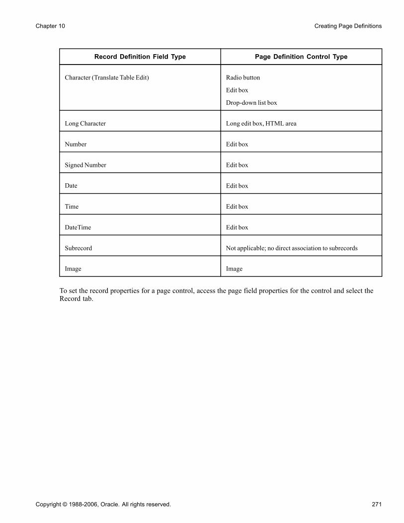
Chapter 10 Creating Page Definitions
Record Definition Field Type Page Definition Control Type
Character (Translate Table Edit) Radio button
Edit box
Drop-down list box
Long Character Long edit box, HTML area
Number Edit box
Signed Number Edit box
Date Edit box
Time Edit box
DateTime Edit box
Subrecord Not applicable; no direct association to subrecords
Image Image
To set the record properties for a page control, access the page field properties for the control and select theRecord tab.
Copyright © 1988-2006, Oracle. All rights reserved. 271

Creating Page Definitions Chapter 10
Edit Box Properties dialog box: Record tab
Note. This section applies to both edit boxes and long edit boxes. Other controls may contain only a few,if any, of the properties listed in the following tables. Refer to the discussion of the specific control formore information.
Record Name Select the record name of the record definition where the field is located.If you already added a field to your page and associated it with a recorddefinition, the system uses the last record definition name that you entered.
Field Name Select the field name. If the field is a related display field that contains a longname or short name from the translate table, use PSXLATDEFN as therecord definition name. The field name is either long name (30 characters)or short name (10 characters), depending on whether you want to use thelong or short name.
Style Set the font and color attributes of your control data. The default style class foran edit box is PSEDITBOX, which controls how the data portion of the editbox appears. Control the color, font, and other characteristics of an edit box byspecifying a different style class.
Note. Certain browsers always display the background of an edit box as white.
272 Copyright © 1988-2006, Oracle. All rights reserved.

Chapter 10 Creating Page Definitions
See "Troubleshooting Browser Limitations" on Customer Connection.
SizeAfter you link the control with a record name and field, the system automatically calculates the page controlsize. The size is based on the length of the field that is defined in your record definition, the font metrics of thefield style, and any formatting options (currency symbol, 1000 separators, and so on) that apply. Becausemany fonts have variable width characters (for example, a W character is much wider than an l character)three size options are available.
Note. Some browsers do not support custom sizing for edit boxes, long edit boxes, drop-down list boxes,and push buttons.
See "Troubleshooting Browser Limitations" on Customer Connection.
Average Select to provide sufficient space to display the field control length inaverage-width characters.
Maximum Select to provide enough space to display the field control length inmaximum-width characters.
Custom Select to define a custom size for edit boxes that are not display-only. If youset a display-only edit box to Custom, it appears as its defined length. If youredit box is in a grid, this field wraps.
AlignmentAlignment in this case indicates the runtime alignment of data within a page field. These settings haveno affect on the relative alignment of page fields.
Auto Select to left-justify the contents of character fields and right-justify thecontents of number and signed number fields. This is the default.
Left Select to left-justify the contents of the field.
Note. If the field is not display-only, the alignment is always left-justified. Ifthe field is display-only, the system uses the alignment that you specify.
Right Select to right-justify the contents of the field. Do not use this option in thePeopleSoft Pure Internet Architecture for fields that are not display-only.
Family Name Displays the current family name, which was set when the field was created,if it’s applicable to your control .
Display Name Select an option to override the display format that is associated with a field.
Display Options
Display Zero Select if the contents of the page control are numeric and you want to display azero value instead of a blank field. Sometimes it helps users if they see a zero toremind them that the page control isn’t blank. For example, in a tax table, youmight show the lowest tax bracket as starting at zero instead of leaving it blank.
Display Century Select for date fields to enable users to enter a date with a four-digit century, asin 1999. Dates are always stored with the four-digit century in the database,
Copyright © 1988-2006, Oracle. All rights reserved. 273

Creating Page Definitions Chapter 10
but only the last two digits are displayed unless you select Display Century. Ifthis option is not selected, the century is automatically set to the century ofyour system date.
Password Select to hide the value that is entered in a page control. This option causescharacters in this control to appear online as asterisks (*). The componentprocessor still sees the actual value. Use this option for pages that capturesensitive information, such as personal identification numbers (PINs).
Currency Symbol Select to display a currency symbol in the field. This expands the displaylength of the field by the length of the currency symbol.
Show Prompt Button Select to display a prompt button next to the edit box, which enables the userto look up valid values for that field.
1000 Separator Select if the contents of the page control are numeric and you want toinsert thousand separators to make the numbers easier to read. The systemautomatically calculates the number of thousand separators to insert anddetermines where they should be positioned. This expands the display lengthof the edit box by one character for each separator.
Auto Fill Select to have the system automatically populate the page control with thecharacter specified in the Fill Character field. The direction in which itpopulates depends on the alignment that you select. If a field is left-aligned,then it populates from left to right. If a field is right-aligned, it populatesfrom right to left.For example, suppose that you define a six-character control as left-aligned,specify a fill character of 0, and activate Auto Fill. When you type 123 inthe control online, the system displays 123000. Similarly, if you changed thealignment to right, the system displays 000123.
Note. Auto Fill can affect the actual value of the control, not just its visualrepresentation.
Auto Decimal Select to insert a decimal point automatically if none is provided in the datathat is entered into the control. Where the system inserts the decimal pointdepends on how you define the control.For example, in a record definition, if you define a numeric field with a lengthof 4.2 (allowing four characters to the left of the decimal and two to the right)and activate Auto Decimal, the system inserts a decimal at the second digitfrom the right. This option applies only to numeric field controls and affectsthe actual value of the field control, not just its visual representation.
Display Time Zone Select if you are setting the properties for a Time or a DateTime field andyou want to display the related time zone. This helps users understandwhether the time reflects the database’s base time zone or some other timezone. This setting does not determine which time zone is actually used, onlywhether the time zone is displayed. The record field properties determinewhich time zone is used.
Enable Spell Check For edit boxes and long edit boxes only; enables the user to check spellingon field content. This feature supports 17 languages using 36 dictionaries.Users have the option of selecting the appropriate dictionary to meet thelanguage needs.
274 Copyright © 1988-2006, Oracle. All rights reserved.
Chapter 10 Creating Page Definitions
The behavior of this feature is as follows:
• Design time behavior: The default setting is Off. When theEnable SpellCheck check box is selected, the Show Prompt Button option is cleared anddisabled—a field can either be spell checked or validated, but not both. Likethe Look-Up button, the spell check button appears to the right of the fieldand is not visible on the page definition. Be sure to leave extra space toaccommodate it when placing other fields on the page.
• Runtime behavior: The spell check button appears to the right of the editbox and at the upper right corner of a long edit box. Each click of the spellcheck button forces a transmission to the application server, opening theSpell Check page. The user then has the option to accept or reject therecommended spelling for the individual word or for all incidences of theterm in the field. If there are no misspellings, a message box indicates thiswithout leaving the current page. The ALT+5 hot key invokes spell checkwhile cursor focus is on the spell check field.
The spell check feature uses the current session language when applyinga foreign language dictionary, unless the user changes it by means ofPersonalizations. The system uses PSLANGUAGES to provide theSCLANG default for each supported session language.
Fill Character Enter a character to replace blank spaces in an edit box when the contents ofthe field are displayed. For instance, if the length of a Net Pay field is 8.3 andyou specify a fill character of *, then a value of $1,250 is displayed as:*****$1,250.000You can use any character as a fill character.
Example: Auto DecimalThis table shows how Auto Decimal affects a numeric field control with a length of 4.2, depending on whatyou enter online:
Entered Displayed
100 1.00
100. 100.00
1 0.01
Setting Label PropertiesThe Label tab enables you to set the label that appears on the control. This can be the long or short namethat is specified on the record definition or other text. Use this tab to verify the label ID that is used asthe internal reference.
Access the page field properties for the control and select the Label tab.
Copyright © 1988-2006, Oracle. All rights reserved. 275

Creating Page Definitions Chapter 10
Long Edit Box Properties dialog box: Label tab
Note. This section applies to the following controls: edit boxes, long edit boxes, check boxes, drop-down listboxes, group boxes, radio buttons, and static text.
TypeSelect the type of label. If you want the label to remain blank, you must first set up a blank label in the fielddefinition that you are using. The blank label then appears as an option in the Label ID drop-down list box.
None Select to display no control label on the page. Use this option for controlssuch as related displays.
Text Select to display text that you enter in the Text field. The default text is thelong name for the field from the associated record definition.For translation purposes, avoid using this option if possible.
RFT Short (record fieldtable short)
Select to display the RFT short name for the field from the associatedrecord definition.
RFT Long (record fieldtable long)
Select to display the RFT long name for the field from the associated recorddefinition. This is the default.
Label Text
Text Enter the text exactly as it should appear on the page. The default is DummyName until you assign a record and field to the control. This field is only
276 Copyright © 1988-2006, Oracle. All rights reserved.

Chapter 10 Creating Page Definitions
enabled if you selected Text as the type. Otherwise, it displays the label textassigned to the field for the Label ID you select.
Label ID Select from the drop-down list box the label you want to appear for the pagefield. The choices available here are based on the Label ID column and theLong Name column for the selected field definition.The default setting for this option is Use Default Label. This default isdetermined by the label you select as the default for the field definition.
Insert Line Feed Click to split your control label into multiple lines at the position of the cursorin the Text field. A thick vertical bar character appears in the Text field. Whenyou close the properties dialog box, the label is split into multiple lines. Thisoption is only active when you select Text for the Type.
Style Select an option to control the color, font, and other characteristics of a label.If you do not select a different label style from the default, Use Default Style,the system uses the label style specified on the style sheet on the PeopleToolsOptions page.
AlignmentThe label alignment in the page field properties controls the alignment for both page fields placed on a pageand page fields as grid columns. For a grid column, the label becomes the column heading and is alignedwithin the column boundaries as specified by this attribute, either left, centered, or right.
Left Select to align the label to the left-of-center horizontally. This is the default.
Centered Select to center the label horizontally.
Right Select to align the label to the right-of-center horizontally.
PositionThese position options are available for edit boxes, long edit boxes, and drop-down list boxes only.
Left Positions label immediately adjacent to the left side of the field. Left is thedefault position of the label for fields newly added to the page. If you movethe label on the page from the left position, PeopleSoft Application Designerchanges the selection to Custom.
Top Positions label above the field. Selecting this option automatically moves thelabel to the top of the field. If you later move the label on the page from the topposition, PeopleSoft Application Designer changes the selection to Custom.
Custom Indicates that the label has been manually moved on the page. Labels canbe adjusted using the keyboard arrows. Selecting this option does notautomatically move the label on the page.
See Chapter 10, “Creating Page Definitions,” Moving Labels, page 270.
To set labels to the left position for individual page fields:
1. Select the control that you want to affect.2. Select Layout, Left Label Position.
Copyright © 1988-2006, Oracle. All rights reserved. 277

Creating Page Definitions Chapter 10
This option is only enabled if the label is set to the custom position. The system moves the label for thatcontrol to the left position. The position indicator in the page field properties does not change from Custom.Note that you may need to readjust the positioning of other fields and labels to accommodate this change.
Note. If you move a page field label manually on the page, the label position in the page field properties dialogbox automatically updates to Custom.
Display Options
First occurs only Select to display the label only with the first occurrence of a child pagefield in a scroll area.
No colon Select this option if you do not want a colon to display at the end of thelabel text. This option is selected by default for edit boxes, long edit boxes,and check boxes.
Special Label ConsiderationsIf you’re adding a related display page control with a label type of None, enter an information-only label thatidentifies the related field but that isn’t identical to the label on the control field. A little documentation nowcan save you time in the future, should you modify this page again. For example:
Control Label Related Field Label (Information-Only)
Department Department Description
Jobcode Jobcode Description
Regular/Temporary Regular/Temporary XLAT (XLAT is from the TranslateTable)
When defining labels for columnar controls in a multi-occurrence scroll, you can apply several techniques.The first technique is to select First occurs only. This limits the display of the label to the control’s first scrolloccurrence, allowing the label to be used as a column heading. The second technique is to select No colon toomit the colon from the label, because column headings typically do not need a colon.
Setting Use PropertiesThe Use tab defines how to use the page field on the page. You can make fields display-only or invisible. Usethis tab to define the display and related control fields and the processing of the control.
Access the page field properties for the page control and select the Use tab.
278 Copyright © 1988-2006, Oracle. All rights reserved.
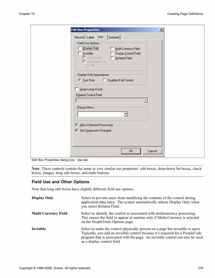
Chapter 10 Creating Page Definitions
Edit Box Properties dialog box: Use tab
Note. These controls contain the same or very similar use properties: edit boxes, drop-down list boxes, checkboxes, images, long edit boxes, and radio buttons.
Field Use and Other OptionsNote that long edit boxes have slightly different field use options.
Display Only Select to prevent users from modifying the contents of the control duringapplication data entry. The system automatically selects Display Only whenyou select Related Field.
Multi-Currency Field Select to identify the control as associated with multicurrency processing.This causes the field to appear at runtime only if Multi-Currency is selectedon the PeopleTools Options page.
Invisible Select to make the control physically present on a page but invisible to users.Typically, you add an invisible control because it’s required for a PeopleCodeprogram that is associated with the page. An invisible control can also be usedas a display control field.
Copyright © 1988-2006, Oracle. All rights reserved. 279

Creating Page Definitions Chapter 10
Display Control Field Select to indicate that the field controls another field on the same pagelevel. The controlled field is a related field. For example, on many pages,Department ID is the display control field and Department Name is the relatedfield. The system uses Department ID to retrieve Department Name from theDepartment table to display on the page.
Show Label Select to make the control label visible while the control itself is invisible. Thisoption is useful if you add an invisible display control field to a page to showits related description. Show Label is selected only if Invisible is selected.
Related Field Select to specify that the contents of this control are ruled by another controlon the same page level—one that you selected as a display control field. Whenyou select this check box, the system automatically selects the Display Onlyoption. It also makes the Related Control Field drop-down list box availablefor you to select the related control field.When you select Related Field, Display Only is automatically selected. If therelated field is located on a record definition with multiple keys, relate thedisplay field to the lowest-order key field that both record definitions have incommon—with the exception of EFFDT and EFFSEQ—on the control recorddefinition. The system searches for the higher order keys by matching fieldcontrol names on the current level and all higher levels for the other keys.If the related display field contains a long name or short name from theTranslate Table, use PSXLATDEFN as the record definition name.
Modifiable by JavaScript This is a security-related feature and should always be cleared unless youare familiar with modifying an invisible field using JavaScript in an HTMLarea. If the Invisible check box is cleared, Modifiable by JavaScript is clearedand unavailable for entry. If the Invisible check box is selected, this checkbox is cleared, by default.
Expand Field when DisplayOnly
Select to make a long edit box expand at runtime to display all the text itcontains when it is marked as Display Only. The field automatically expandsto accommodate text. This is option available for long edit boxes only. Thischeck box is cleared, by default. When selected, this option enables theWrap Long Words option.
Wrap Long Words Wraps long words that do not contain spaces, such as long URLs, in a pagefield at runtime for Microsoft Internet Explorer only. The word wraps to thelength of the field set at design time. Other browsers automatically stretchthe width of the page to accommodate the longer text. This option has noimpact at runtime to applications running on browsers other than MicrosoftInternet Explorer. This setting is cleared by default.
Wrap Long Words is available for edit boxes, long edit boxes, and drop-downlist boxes only. It can be applied to stand alone page fields and grid columns.For edit boxes and drop-down list boxes, this option is disabled if DisabledEdit Control is selected. For long edit boxes, this option is available only if theExpand Field When Display Only option under Field Use Options is selected.
280 Copyright © 1988-2006, Oracle. All rights reserved.

Chapter 10 Creating Page Definitions
Note. The system does not restrict an edit box or drop-down list box that isconfigured as Display Only and Text Only to one line of height. The text iswrapped to the next line as necessary.
Also, the Wrap Long Words property does not impact the word wrappingbehavior of shorter words that can be accommodated by the page field size atruntime. This text automatically wraps at word boundaries in accordance withthe page field size regardless of whether this option is set.
Related Control Field When you select Related Field, a list of all controls on the page that are markedas display control fields appears in this drop-down list box. Select the field towhich this control is related. You must define the use of the initial controlfield before it appears as an option in the Related Control Field drop-downlist box. For example, after the Pay Group field is designated as a displaycontrol field, it appears in the Related Control Field drop-down list box for thecontrol that you set as the related field.Note that the number that appears before each entry in the Related ControlField drop-down list box is the page field order number associated withthat entry.
Display-Only AppearanceThe Display-Only Appearance attributes, Text Only and Disabled Edit Control, apply to edit boxes anddrop-down list boxes only. These properties, in conjunction with other attributes you apply to the field, such asDisplay Only on the Use tab or the Gray function in PeopleCode to disable the field, and whether or not thefield is in a grid, control the base style the system uses to render these controls at runtime.
The default base style for a normal edit box, meaning editable and enabled (as opposed to display-only ordisabled), is PSEDITBOX. The default base style for drop-down list boxes is PSDROPDOWNLIST. The basestyle then changes depending on the attributes that you select and where you place your field, as shown by thedefault base style examples in the following table.
If you choose a custom base style for the field on the Record tab of the control properties, the system uses thestyle’s associated display only and disabled variants as appropriate to create the additional looks. For example,if you select XYZ base style, and set the field as display-only, the related XYZ_DISPONLY style is usedif it exists, otherwise the base XYZ style is used.
Copyright © 1988-2006, Oracle. All rights reserved. 281
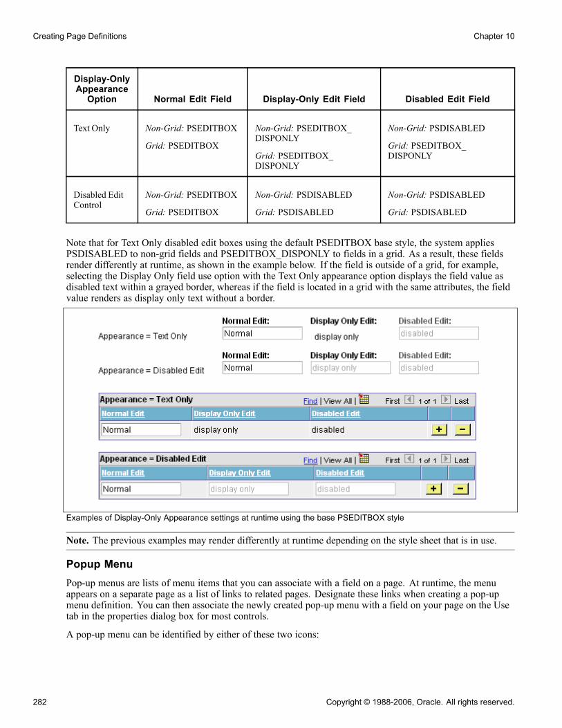
Creating Page Definitions Chapter 10
Display-OnlyAppearanceOption Normal Edit Field Display-Only Edit Field Disabled Edit Field
Text Only Non-Grid: PSEDITBOX
Grid: PSEDITBOX
Non-Grid: PSEDITBOX_DISPONLY
Grid: PSEDITBOX_DISPONLY
Non-Grid: PSDISABLED
Grid: PSEDITBOX_DISPONLY
Disabled EditControl
Non-Grid: PSEDITBOX
Grid: PSEDITBOX
Non-Grid: PSDISABLED
Grid: PSDISABLED
Non-Grid: PSDISABLED
Grid: PSDISABLED
Note that for Text Only disabled edit boxes using the default PSEDITBOX base style, the system appliesPSDISABLED to non-grid fields and PSEDITBOX_DISPONLY to fields in a grid. As a result, these fieldsrender differently at runtime, as shown in the example below. If the field is outside of a grid, for example,selecting the Display Only field use option with the Text Only appearance option displays the field value asdisabled text within a grayed border, whereas if the field is located in a grid with the same attributes, the fieldvalue renders as display only text without a border.
Examples of Display-Only Appearance settings at runtime using the base PSEDITBOX style
Note. The previous examples may render differently at runtime depending on the style sheet that is in use.
Popup MenuPop-up menus are lists of menu items that you can associate with a field on a page. At runtime, the menuappears on a separate page as a list of links to related pages. Designate these links when creating a pop-upmenu definition. You can then associate the newly created pop-up menu with a field on your page on the Usetab in the properties dialog box for most controls.
A pop-up menu can be identified by either of these two icons:
282 Copyright © 1988-2006, Oracle. All rights reserved.

Chapter 10 Creating Page Definitions
This page field icon appears if the pop-up menu contains more than one item.The user goes to a new page to select among the menu items listed.
Note. This icon also appears if PrePopup PeopleCode is associated withthe pop-up menu and there is only one item remaining in the list after thePeopleCode has run. The transaction page opens automatically.
This page field icon appears if the pop-up menu contains only one menu item.In this case, the user goes directly to the assigned transaction page.
Allow Deferred Processing Enables deferred processing for this page field. A transaction can run in twomodes: deferred and interactive.
Set Component Changed Enables the system to issue a save warning for the field if the user changesthe value and attempts to exit the page before saving. This setting reinforcescurrent save warning behavior. This option is set by default for edit boxes,long edit boxes, radio buttons, check boxes, and drop-down list boxes.Clearing this option overrides the save warning that normally displays to users.The user will not see a save warning after changing the value of the field andattempting to exit the page. An example of when this might be necessary isfor a drop-down list box that includes links to another page. If the userselects a link from this field to transfer to another page but has not made anyother changes to the page, it is not necessary for the system to issue a savewarning. By clearing the Set Component Changed flag, you insure that nosave warning message is issued for this field.This option works for fields associated with a derived work field or databaserecord field.This option is also available for the push button/hyperlink control though thedefault setting is cleared instead of selected.
See Chapter 9, “Using Page Controls,” Inserting a Push Button or Link,page 231.
Setting General PropertiesThe General tab enables you to specify an optional internal page field name that is referenced by the page.
Access the page field properties for the control and select the General tab.
Copyright © 1988-2006, Oracle. All rights reserved. 283

Creating Page Definitions Chapter 10
Edit Box Properties dialog box: General tab
Note. For most controls, the General tab contains only the Page Field Name and Enable as Page Anchorsettings. Grids and scroll areas have additional settings on the General tab that are described later. The Enableas Page Anchor check box is available for all controls that have a page field name.
Page Field Name Enter a name for the page field that you are creating. This is a system-onlysetting. It does not appear as the label for the page field. The page field nameenables you to refer to a particular field on a page using PeopleCode.This setting is optional unless you select the Enable as Page Anchor check box.
Enable as Page Anchor Select to apply an anchor tag to the current page field on the page. If you selectthis check box, you must add a page field name to identify this field whensetting the related control for the link. This check box is cleared, by default.
See Chapter 9, “Using Page Controls,” Specifying Destination Types, page232.
284 Copyright © 1988-2006, Oracle. All rights reserved.

Chapter 10 Creating Page Definitions
Creating Display Control and Related FieldsThis section discusses how to:
• Use display control and related fields.
• Create related edit fields.
• Create invisible control fields.
Using Display Control and Related FieldsA related display field is for display purposes only—it always references a row that’s not being updated fromthe current page. The display control and related display fields must both be at the same level. In the Payrollpage, the Pay Group, Employee Type, Tax Location Code, and Holiday Schedule fields all show related displayfields to their right. Search level fields, such as those shown above the horizontal rule, are display-only fields.
Payroll page
Because of the nature of control fields and related fields, PeopleSoft recommends that you:
• Place them side-by-side on a page to indicate their relationship.• Provide adequate space between the fields.• Do not overlap them; otherwise, they appear skewed when viewed through the browser.• Change the label type for the related field to None so that it doesn’t appear on the page.• Enter a text description to document the purpose of the field.
Note. The display control and related fields must be in the correct order on the order page. The display controlfield must be positioned before the associated related field; otherwise, a warning dialog box appears whenyou save the page. Also, fetching the related field after the control field is entered requires a transmission tothe server at runtime.
Copyright © 1988-2006, Oracle. All rights reserved. 285
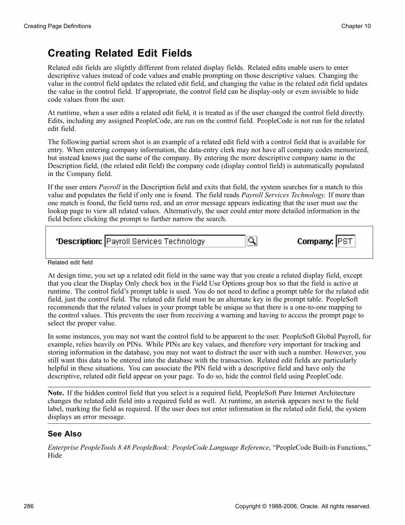
Creating Page Definitions Chapter 10
Creating Related Edit FieldsRelated edit fields are slightly different from related display fields. Related edits enable users to enterdescriptive values instead of code values and enable prompting on those descriptive values. Changing thevalue in the control field updates the related edit field, and changing the value in the related edit field updatesthe value in the control field. If appropriate, the control field can be display-only or even invisible to hidecode values from the user.
At runtime, when a user edits a related edit field, it is treated as if the user changed the control field directly.Edits, including any assigned PeopleCode, are run on the control field. PeopleCode is not run for the relatededit field.
The following partial screen shot is an example of a related edit field with a control field that is available forentry. When entering company information, the data-entry clerk may not have all company codes memorized,but instead knows just the name of the company. By entering the more descriptive company name in theDescription field, (the related edit field) the company code (display control field) is automatically populatedin the Company field.
If the user enters Payroll in the Description field and exits that field, the system searches for a match to thisvalue and populates the field if only one is found. The field reads Payroll Services Technology. If more thanone match is found, the field turns red, and an error message appears indicating that the user must use thelookup page to view all related values. Alternatively, the user could enter more detailed information in thefield before clicking the prompt to further narrow the search.
Related edit field
At design time, you set up a related edit field in the same way that you create a related display field, exceptthat you clear the Display Only check box in the Field Use Options group box so that the field is active atruntime. The control field’s prompt table is used. You do not need to define a prompt table for the related editfield, just the control field. The related edit field must be an alternate key in the prompt table. PeopleSoftrecommends that the related values in your prompt table be unique so that there is a one-to-one mapping tothe control values. This prevents the user from receiving a warning and having to access the prompt page toselect the proper value.
In some instances, you may not want the control field to be apparent to the user. PeopleSoft Global Payroll, forexample, relies heavily on PINs. While PINs are key values, and therefore very important for tracking andstoring information in the database, you may not want to distract the user with such a number. However, youstill want this data to be entered into the database with the transaction. Related edit fields are particularlyhelpful in these situations. You can associate the PIN field with a descriptive field and have only thedescriptive, related edit field appear on your page. To do so, hide the control field using PeopleCode.
Note. If the hidden control field that you select is a required field, PeopleSoft Pure Internet Architecturechanges the related edit field into a required field as well. At runtime, an asterisk appears next to the fieldlabel, marking the field as required. If the user does not enter information in the related edit field, the systemdisplays an error message.
See AlsoEnterprise PeopleTools 8.48 PeopleBook: PeopleCode Language Reference, “PeopleCode Built-in Functions,”Hide
286 Copyright © 1988-2006, Oracle. All rights reserved.

Chapter 10 Creating Page Definitions
Creating Invisible Control FieldsYour page design may require an invisible control field. For example, if users are interested only in thecontents of the related display field, then make the control field invisible. Unlike visible control fields, you canoverlap an invisible control field and its related display field.
Note. If you specify a field as invisible in PeopleSoft Application Designer, you cannot make it visibleusing the UnHide property in PeopleCode.
To add an invisible control field with a visible label:
1. Access the properties dialog box for the invisible control for which you want the label to appear.
2. Select the Use tab.
3. Set the appropriate field use options:a. Select Display Only, Invisible, and Show Label to make the field invisible and its label visible.b. Select Display Control Field.
4. Select OK.5. Add an edit box to your page.Place this edit box directly to the right of the display control field that you just set.
6. Access the properties dialog box for the new edit box.7. Select the Use tab.8. Select Related Field.9. Select the appropriate control field from the Related Control Field drop-down list box.10. Select OK.
Ordering and Spacing Page ControlsThis section provides an overview of page control order and spacing and discusses how to:
• Order controls visually.
• Order controls logically.
• Test page control order.
• Apply control order rules.
• Change control order using the order list.
• Find a field on a page definition.
• Use default order.
• Space controls on pages.
Understanding Page Control Order and SpacingThe order of the controls that are on your new page is important to both how your users interact with the pageand how the component processor interprets the underlying record and field relationships.
Copyright © 1988-2006, Oracle. All rights reserved. 287

Creating Page Definitions Chapter 10
Two types of control order are important on pages:
• The order in which you visually arrange controls on the page.
• The logical processing order—governed by levels—that the system requires to correctly process the pagedata.
As you add controls to a page, the system automatically builds a processing control order list that can beviewed on the Order tab of the page definition. Usually, you don’t want to preserve this order for processing,so you can reorder your controls on the Order tab to indicate how the system should process your page.
Ordering Controls VisuallyOrganize fields from top left to bottom right in a page. Include most important information at top. Usegroup boxes to group related fields and indicate the hierarchy of information on a page. Guidelines forgrouping information include:
• KeysGroup all key fields at the top of a page (such as Business Unit, Employee ID, and SetID).
• Level 1−3Controls at these levels must be enclosed by a scroll area or grid. At design time, these levels can bestacked. At runtime, they appear nested.
Ordering Controls LogicallyTab ordering through a page at runtime is strictly defined by page field ordering. When you add a controlto a page, PeopleSoft Application Designer automatically inserts it in the order list based on where youposition it on the page. You can manipulate the ordering of fields on your page by moving them up or downon the Order tab in the page definition. In doing so, you also change the tab order that users follow as theymove through fields on the page.
In general, field tab order should flow from top left to bottom right on a page. The flow should reflect the waythat the eye naturally scans information. On a page with multiple scroll levels, the tab order should follow thescroll level order, from Level 0 to Level 1, and so on. In a noncolumnar page, the tab order should go fromleft to right on each line from top to bottom as depicted in this figure:
Field 1:
Key: Key Value
Field 2: Field 3:
Field 4:
Field 6:
Field 5:
Example flow of noncolumnar page
In a columnar page, the tab order should go from the top to the bottom of the first column, then from thetop to the bottom of the second column, and so on.
288 Copyright © 1988-2006, Oracle. All rights reserved.

Chapter 10 Creating Page Definitions
Field 1:
Key: Key Value
Field 2:
Field 4:
Field 3:
Field 6:
Field 5:
Field 7:
Field 8:
Example flow of columnar page
Fields that share the same label should follow consecutively in the tab order from left to right.
Testing Page Control OrderAfter you have placed all of the controls on your page, you should test the tab order. You can do this usingeither the test mode or by viewing the page in the browser. Using the View Page in Browser mode is moreuseful because you can also check the placement of controls and subfields that are on your page. In thesetesting modes, you can enter data into edit boxes and select radio buttons and check boxes. However, youcannot save data that you enter, and push buttons and links do not function.
Note. The tab order that you establish at design-time may not apply for all browsers.
See "Troubleshooting Browser Limitations" on Customer Connection.
To test tab flow using View Page in Browser mode:
1. Open the page in PeopleSoft Application Designer that you want to test.2. Select Layout, View in Browser.3. Select the appropriate browser from the drop-down list box.4. Press the TAB key to move from one field to the next.Press SHIFT+TAB to move to the previous field.
Applying Control Order RulesIf you’re working with a complex page or you’re new to order lists, you might print out a page definition andwork on the hard copy. The sequence number of each control is reflected in the Num column on the pagereport. You can easily mark where you need to move a control to make your page function properly, or you canlook at the Lvl column on the Order tab of the page definition.
Use these rules to order your controls:
Copyright © 1988-2006, Oracle. All rights reserved. 289

Creating Page Definitions Chapter 10
Radio ButtonsFor radio buttons to function in a single group, they must be associated with the same record field and belisted together on the Order tab of the page definition. The only control that you can place between relatedradio buttons is the static text control to extend radio button labels. Put the text immediately after the radiobutton to which it relates.
Level-Based ControlsList level-based controls (scroll areas, grids, and scroll bars) immediately before the first control that theygovern, followed by the controls that are directly governed by that control. Level-based controls directlygovern all controls that are listed below them on the order list until they encounter another level-based controlthat is at the same or lower level (higher occurs level number).
Display ControlsPlace display controls before related displays that they govern. The related display controls don’t have tofollow the display controls immediately, but they must be inside the same scroll area or scroll. However, ifyou have more than one related display control, placing each immediately following its display controlmakes the order page easier to read and understand.
Changing Control Order Using the Order ListThe Order tab of the page definition displays attributes about each of the page fields and their field order. TheID column represents the order in which the field was added to the page. If you modify the order of pagefields on the page, note that the numbers assigned to each field remain constant. Thus the IDs may notalways appear in sequential order. The field ID displays on the Compare report when a database compare isperformed to assist you in identifying specific page fields.
Reorder page fields on the Order tab by dragging them in the same view. Changing the order list doesn’tchange the physical location of controls on the page. It changes only the logical order or tab order in whichcontrols are processed. When you’ve added and arranged all of your controls, you may want to print yourpage definition to see how you might need to reorder your controls.
The Order tab also governs processing rules for scrolls and record or field relationships. Consider whichcontrols are associated with which scroll area or scroll bar and which secondary relationships are important topage processing.
To change the order list:
1. Open the page.2. Select the Order tab on the open page.The Order view appears. Use this view to change the logical processing order of fields on your page.
3. To move a control to another position in the control order list, select the control that you want to move.Press the SHIFT key to select multiple controls.
4. Drag the selected control to the new position on the Order view.The system moves the control to the new location in the list. The ID value remains static. The visualdisplay of the page still looks the same—changing the order list doesn’t move the control on the page,only the logical processing order of the control.
290 Copyright © 1988-2006, Oracle. All rights reserved.
Chapter 10 Creating Page Definitions
Finding a Field on a Page DefinitionUse the Order view to locate a field on a page definition. Using this method of locating fields is useful whenyou are working with detailed page definitions that contain many fields.
To find a field on a page:
1. Access the Order tab of your page definition.2. Select the field that you want to locate on the page.3. Select the Layout tab.The field that you selected on the Order tab is selected in the Layout view.
Using Default OrderYou can rearrange the order list on the Order tab so that the logical control order reflects the physical controlorder as shown on the Layout tab. Do so by selecting Layout, Default Page Field Ordering. You can use thistool in either the Layout or Order view for your page definition. The system creates the default order byreading the page as though it was on a pixel-by-pixel grid, from top to bottom and left to right.
Note. Use the default ordering option sparingly on existing pages. It may offset any previous order that wascreated. However, on new pages, you may find default ordering a useful starting point for your controlorder list.
Spacing Controls on PagesProvide adequate space between controls on a page so that fields and their labels don’t touch or overlap othercontrols or labels in PeopleSoft Application Designer. If they do, then when your page appears in the browser,the label is offset automatically and the overlapped control might shrink.
Overlapping FieldsYou can layer or overlap fields only if the one that you are overlapping is set to Invisible on the Use tab ofthe properties dialog box for that control. When you move through the data entry controls on a page, thecomponent processor recognizes only visible, unhidden fields as available for entry.
You can layer multiple invisible fields. However, you must set up your stacks of edit boxes so that all but onefield in the stack are invisible or hidden at RowInit time.
Designing Inquiry PagesYou can design pages for inquiry purposes only. Inquiry pages are usually based on search records that extractspecific information from different tables to display different views of your database, such as a summary ofexpenses by department.
To create an effective inquiry page:
• Make all of the fields display-only.• Build in sufficient display control and related field relationships to show relevant descriptions.• When using level-based controls, disable the row action buttons so that the user cannot add or delete rows.
Copyright © 1988-2006, Oracle. All rights reserved. 291

Creating Page Definitions Chapter 10
Job Summary inquiry page
Aligning Page ControlsPage design mode in PeopleSoft Application Designer provides relative alignment functionality in the pagedefinition toolbar to help you ensure that your controls are aligned relative to each other, both horizontally andvertically. The relative alignment tools are enabled when two or more controls on the page are selected.
To align controls on a page relative to one another:
1. Select the controls that you want to align.Select controls by pressing CTRL and clicking each field on the page. Leave the last control to be selectedas the guide, or anchor, by which all other selected controls are aligned. The anchor control does not movewhen you select an alignment button.
Note. Controls can also be selected using the group selection method of dragging the cursor aroundthe controls. However, for relative alignment purposes, the CTRL + click is the preferred method ofselection, because it enables you to explicitly set the anchor control by which the system aligns theother selected controls.
2. Click the appropriate relative alignment button in the toolbar.Relative alignment can also be activated from the Layout menu.Page fields can be moved manually after relative alignment, though previous alignment is not preserved.
See AlsoChapter 10, “Creating Page Definitions,” Selecting Controls, page 267
Maximizing PerformancePage definitions permit controlled access to application data. The system can validate the data, write it to thedatabase, and then retrieve and display it upon request. Behind the scenes, the component processor—thePeopleTools runtime processor—builds SQL statements that are based on the actions that you perform onpages. The component processor:
• Manages the flow of data processing as users enter information on pages.
292 Copyright © 1988-2006, Oracle. All rights reserved.
Chapter 10 Creating Page Definitions
• Issues INSERT, DELETE, and UPDATE statements to maintain data in the database and SELECT statementsto retrieve data.
As you design your pages, some features can adversely affect page performance. There’s always a tradeoffbetween eliminating a useful feature and speeding up page processing. Guidelines for improving pageperformance include:
• Be judicious about references to record definitions other than the primary record definition under eachscroll area.References to other record definitions can include:- Related display controls.- PeopleCode references (such as edits and defaults) to other records.- Defaults to fields on other record definitions.- Field controls on derived or work records.
• Put the field control on the appropriate derived or work record, rather than on a regular data record definitionto derive its value.For example, FTE (full-time equivalent) on the JOB record definition would be moved to the DERIVED_HRderived or work record because its value is derived by the system.
• Use as few record definitions as possible in a component.When you open a page in a component, the system loads all record buffers from the entire componentinto buffers.
• Do not remove table edits to improve performance, even though an edit against another table causes ashort pause.Eliminating them may compromise data integrity.
• Frames, scroll areas, scroll bars, grids, and group boxes all create HTML tables, which, in some browsers,might slightly degrade the performance of your system.Be judicious about the number of these types of controls that you use on a page.
• Apply deferred processing when possible to fields, pages, and components.
See AlsoChapter 8, “Designing Pages for Optimal Performance and Accessibility,” page 179
Enterprise PeopleTools 8.48 PeopleBook: PeopleCode Developer’s Guide, “PeopleCode and the ComponentProcessor”
Accessing PeopleCode in Page DefinitionsPage fields are associated with a specific record field. You can access the PeopleCode for that record fieldfrom the page field in the page definition. You might add PeopleCode to a field to achieve a variety of tasks,ranging from real-time editing of fields to altering the appearance of fields on a page. You can also associatePeopleCode with a component, component record, and component record field.
Copyright © 1988-2006, Oracle. All rights reserved. 293

Creating Page Definitions Chapter 10
Editing PeopleCode
To edit or add record field PeopleCode through a page definition:
1. Select File, Open to open the page definition through which you want to access PeopleCode.2. Select the field on the page for which you want to view the associated PeopleCode.3. Select View, View Record PeopleCode.The PeopleCode editor appears, providing access to all of the PeopleCode for the record that owns that field.
4. Select the PeopleCode event type from the drop-down list box in the PeopleCode editor.You can also select other fields in the primary record from that drop-down list box.
5. Select File, Save to save your changes.
See AlsoEnterprise PeopleTools 8.48 PeopleBook: PeopleCode Developer’s Guide, “Accessing PeopleCode andEvents”
Viewing Pages in the BrowserThis section discusses how to:
• Work with the View in Browser feature.• Change the default browser.• Generate HTML.• View the HTML for a page.• Identify page definitions online.
294 Copyright © 1988-2006, Oracle. All rights reserved.

Chapter 10 Creating Page Definitions
Working With the View in Browser FeatureDuring the page design process, you should periodically view how your page looks in the browser. How youdesign your page in PeopleSoft Application Designer may look different when viewed online, particularly ifyou are using subpages that contain multiple fields.
To do this, select Layout, View in Browser. This feature is helpful if you are changing any of the stylecharacteristics of the page or aligning and spacing controls, such as scroll areas.
Sample page in PeopleSoft Application Designer
Copyright © 1988-2006, Oracle. All rights reserved. 295
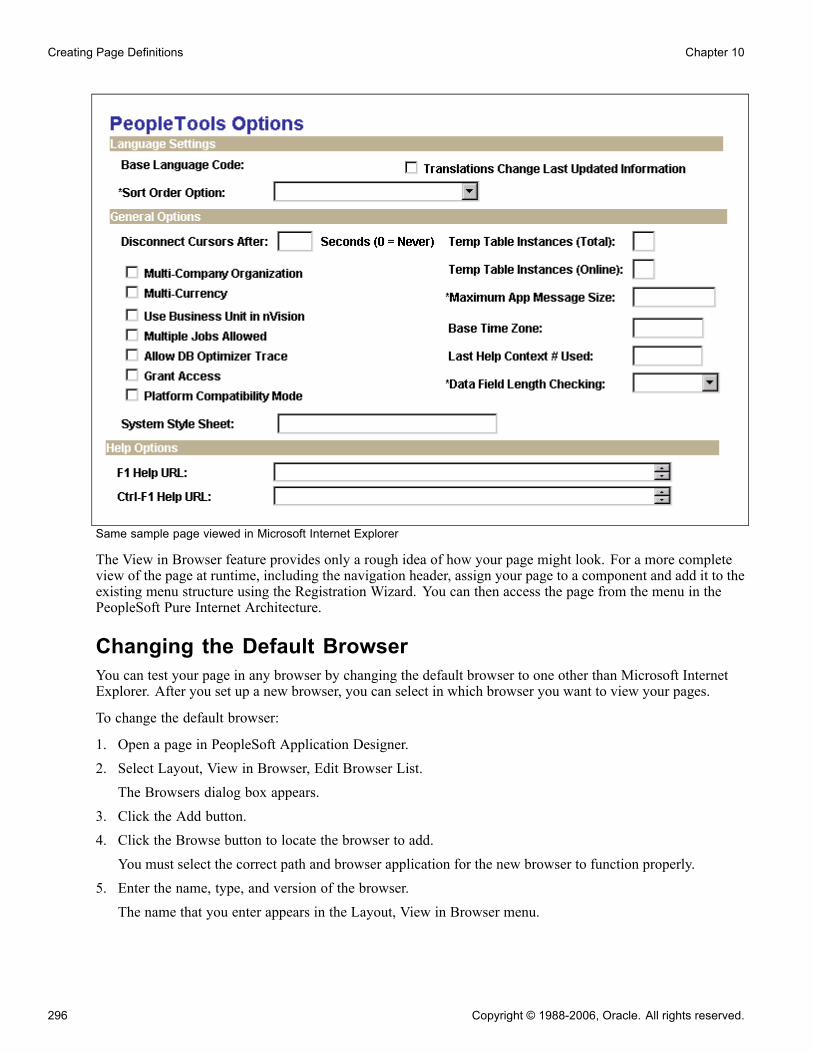
Creating Page Definitions Chapter 10
Same sample page viewed in Microsoft Internet Explorer
The View in Browser feature provides only a rough idea of how your page might look. For a more completeview of the page at runtime, including the navigation header, assign your page to a component and add it to theexisting menu structure using the Registration Wizard. You can then access the page from the menu in thePeopleSoft Pure Internet Architecture.
Changing the Default BrowserYou can test your page in any browser by changing the default browser to one other than Microsoft InternetExplorer. After you set up a new browser, you can select in which browser you want to view your pages.
To change the default browser:
1. Open a page in PeopleSoft Application Designer.2. Select Layout, View in Browser, Edit Browser List.The Browsers dialog box appears.
3. Click the Add button.4. Click the Browse button to locate the browser to add.You must select the correct path and browser application for the new browser to function properly.
5. Enter the name, type, and version of the browser.The name that you enter appears in the Layout, View in Browser menu.
296 Copyright © 1988-2006, Oracle. All rights reserved.

Chapter 10 Creating Page Definitions
Generating HTMLThe PeopleSoft Pure Internet Architecture system automatically writes HTML forms or tags for all of thepage controls that you add to a page. You do not need to know how to write HTML code to create pages inPeopleSoft Application Designer and then view them in the browser. The table shows this conversion:
Page Controls as HTML
Page Controls HTML Forms Static HTML Tags
Edit Box (editable) <INPUT TYPE=TEXT> N/A
Long Edit Box <TEXTAREA> N/A
Drop-down List Box <SELECT><OPTION><OPTION>…</SELECT> N/A
Radio Button <INPUT TYPE=RADIO> N/A
Check Box <INPUT TYPE=CHECKBOX> N/A
Push Button or Link <INPUT TYPE=BUTTON>
<INPUT TYPE=HYPERLINK>
N/A
Static Text N/A HTML text
Static Image N/A <IMG>
Grid N/A HTML <TABLE>
You can view the HTML that is created for your page by using the Generate HTML feature. The GenerateHTML feature writes the HTML code to a file on the local drive. This feature is mainly used for debuggingpurposes and is not needed for the creation of pages.
To generate HTML for a page:
1. Open the page for which you want to generate the HTML.2. Select Layout, Generate HTML.3. Select the browser type and version.PeopleSoft Application Designer generates the HTML to the c:\TEMP\pshtml directory. The file isnamed according to the page name and the browser that you select. For example, the Absence Historypage is named ABSENCE_HISTORY IE5.00.html.
Viewing the HTML for a PageTo view the HTML for your page:
Copyright © 1988-2006, Oracle. All rights reserved. 297

Creating Page Definitions Chapter 10
1. Open the generated HTML file.The selected browser appears, displaying how your page appears at runtime.
2. Select View, Source in your browser window.Notepad or another text-based application appears with the HTML that was used to create your page.
Note. Different browsers might have different methods for viewing the HTML for your page.
To adjust the look or function of how your page looks in the browser, do so in PeopleSoft ApplicationDesigner. If you make changes directly to the HTML in Notepad, your changes are not saved to the system.Each time that you open the page in the browser, it reverts to the settings of the original page definition.
Identifying Page Definitions OnlineIn some cases, the page name online differs from the actual name of the page definition in PeopleSoftApplication Designer. While viewing a page in the browser, locate the page definition name by right-clickingthe page and selecting View Source from the drop-down menu. The HTML code appears for your page in a textapplication, such as Notepad. In most cases, the page name is in the sixth or so line of code after Page:. Youcan also identify the component and menu definitions for your page next to the page definition name.
Page definition name identified in HTML code
298 Copyright © 1988-2006, Oracle. All rights reserved.
Chapter 10 Creating Page Definitions
Producing PagesThis section provides an overview of page production and discusses how to:
• Change general page information.
• Change page use information.
• Save pages.• Rename and delete pages.
• Print page definitions.
• Alter page setup.
• Read your page definition report.
Understanding Page ProductionIf you are changing pages or deleting controls in the page definition, use the tools in the Edit and File menus.To avoid making changes that might adversely affect your application database, review your plans withyour database administrator. Together, you can evaluate the impact that your actions might have on yoursystem database as a whole.
There are several additional steps in the page design process that help make future editing of page definitionseasier.
After you design your page, you must set the attributes for how your page should function and make sure thatyou have the proper documentation to assist you when performing upgrades. Access the Page Properties dialogbox by selecting File, Definition Properties in page definition mode.
Use the General tab in the Page Properties dialog box to document the page. Enter both short and longdescriptions of the page here. You can also document what changes have been made, or must be made,to a page.
Changing General Page InformationAccess the Page Properties dialog box. Select the General tab. Enter a description and any comments about thepage and assign an Owner ID.
Copyright © 1988-2006, Oracle. All rights reserved. 299

Creating Page Definitions Chapter 10
Page Properties dialog box: General tab
Changing Page Use InformationAccess the Page Properties dialog box. Select the Use tab.
300 Copyright © 1988-2006, Oracle. All rights reserved.

Chapter 10 Creating Page Definitions
Page Properties dialog box: Use tab
Page Type Use the standard page, or select subpage or secondary page from thedrop-down list box.
See Chapter 9, “Using Page Controls,” Understanding Subpages, page 208.
See Chapter 9, “Using Page Controls,” Understanding Secondary Pages,page 246.
Page SizeTo accommodate different types of workstation monitors, you can adjust the page size.
800x600 page inside portal This is the standard option for viewing pages in the portal, making room forthe universal navigation header and the menu. It provides a default page sizeof 570 × 330 in PeopleSoft Application Designer.
800x600 page withoutportal
Most pages should be developed using this option. It is the standard option forviewing pages, making room for the navigation header and the menu. Thisoption provides a default page size of 760 × 330 in PeopleSoft ApplicationDesigner.
Copyright © 1988-2006, Oracle. All rights reserved. 301

Creating Page Definitions Chapter 10
1024x768 page inside portal Selecting this option provides an optimal display for users with a 1024 x 768resolution, showing the full transaction page and the menu. Users with an800x600 display, will see the full transaction page without the menu when themenu is enabled. This option provides a default page size of 760 x 498 inPeopleSoft Application Designer.
1024x768 page withoutportal
For the power user, this is a high-resolution option. It provides a default pagesize of 984 × 498 in PeopleSoft Application Designer.
240xVar portal home pagecomp.(240 x Variable portalhome page component)
Use only for creating pagelets for the portal. This size is most usable becauseit can be viewed in both the narrow area and the wide area of the portal. Whilethe width is set to 240, you can set the height.
490xVar portal home pagecomp.(490 x Variable portalhome page component)
Use only for creating pagelets for the portal. This size can be displayed only inthe wide area of the portal. While the width is set to 490, you can set the height.
640x480 Windows screen Deprecated feature used only for Windows client users. This is designed forVGA resolution. The pages are actually less than 640 × 480 pixels in sizein PeopleSoft Application Designer, because they provide space for variouswindows items, such as the window title, menu bar, and toolbar.
800x600 Windows screen Deprecated feature used only for Windows client users. This is designed forSuper VGA resolution. These pages provide space for the window title,menu bar, toolbar, folder tabs, and status line, as well as space at the bottomfor the taskbar.
Custom size Select to set a specific page size other than those listed previously. Set thewidth and height manually.
Note. As a licensee of PeopleTools, you are licensed to use the base portal technology, which is limited tonavigation to licensed PeopleSoft applications. If you want to register additional non-PeopleSoft content,customize your homepage, or create any pagelets, you must license PeopleSoft Enterprise Portal.
Style
Page Style Sheet Select a different style sheet for a specific page to override the style sheet thatis selected for the application. If you do not select a different page style sheet(keeping ***Use Default Style***), the system uses the style sheet that isspecified on the PeopleTools Options page.
Page Background Select a different page background style class to override the background styleof the page style sheet specified above. If you keep the ***Use DefaultStyle***, the background of this page is determined by the default backgroundof the page style sheet.
Note. The style options you select do not necessarily appear the same in the design time and runtimerendering of the page. For example, font and page control sizing metrics are different in the design timeWindows environment and the runtime browser environment. As such, when developing pages, do notrely entirely on the rendering of the page in PeopleSoft Application Designer to gauge layout issues, suchas font size and the placement of controls. All pages should be viewed in the runtime browser environmentand adjusted accordingly.
302 Copyright © 1988-2006, Oracle. All rights reserved.

Chapter 10 Creating Page Definitions
Additional Settings
Adjust Layout for HiddenFields
Select to set the page to resize automatically when hidden fields are present.
Pop-Up Menu See Chapter 12, “Creating Menu Definitions,” Defining Pop-up Menus,page 334.
Allow Deferred Processing Clear if you want the page and all of its fields to follow standard processing.Deferred processing is the default.
Saving PagesTo save your work, select File, Save or File, Save As.
When you save your page, the system performs various edits and issues warning messages as appropriate. Thewarning explains any errors that are associated with each control. You can disregard these messages and saveyour work anyway, but you cannot view the page in the browser until all errors are corrected.
Access the explanation of an error message by clicking the Explain button in the warning message box. Youcan fix the problem immediately or save the page and return later to correct it.
Renaming and Deleting PagesIf you rename a page, the change is reflected throughout the system, including PeopleCode, so you don’t haveto change the page name anywhere else.
To delete a page, particularly a subpage or a secondary page, first use the Find Definition References option todetermine which page, component, and menu definitions refer to or use the page you want to delete.
See AlsoChapter 2, “Using PeopleSoft Application Designer,” Renaming Definitions, page 29
Chapter 2, “Using PeopleSoft Application Designer,” Deleting Definitions, page 31
Chapter 2, “Using PeopleSoft Application Designer,” Finding Definitions, page 32
Printing Page DefinitionsTo keep track of your application definitions and refinements, print your page definitions and keep a log orbinder with your new and revised pages as you reconfigure your applications. You may want a reference foreach page that includes both the onscreen image and the page control information (the record definitions andspecial uses or edits that you’ve applied), as well as the information for any subpages that are includedin the page definition.
Printing page definitions also helps you debug during testing. Each report includes a unique identifier that’sautomatically incremented by the system each time that you change the page.
To print a page definition:
1. Open the appropriate page.2. Select File, Print.
Copyright © 1988-2006, Oracle. All rights reserved. 303

Creating Page Definitions Chapter 10
Altering Page SetupAccess the Print Setup dialog box by selecting File, Print Setup.
PrintAll print options are selected, by default.
Definition Select to print the list of fields on the page and all of the parameters thatyou’ve set for each one.
PeopleCode Select if you used PeopleCode to design your page
Graphics Select to provide a snapshot of your page design. Graphics generally takelonger to print than page descriptions or PeopleCode reports.
Borders
Header Select to print a header at the top of the report indicating the date and time thatyou printed the report and the database name, page name, version number, andpage number. The default is selected.
Footer Select to print a footer at the bottom of the report indicating the date and timethat you printed the report and the database name, page name, version number,and page number. The default is cleared.
Border Select to print a border or box around a page report. The default is cleared.
Border Space (mm) Select to insert a set amount of space between a graphical border aroundthe page report and the margins of the report. Clear this option to print incharacter mode (faster), rather than in graphics mode (slower). The defaultspace is 3 mm, but can be changed.
Margins (mm)Set the distance from the edge of the page to the left, right, top, and bottom edges of the page image orreport. The defaults are:
• Top: 20.• Bottom: 5.• Left: 10.• Right: 0.
Note. PeopleSoft has selected the HP LaserJet as the default printer.
Reading Your Page Definition ReportThis table lists the columns on the page definition report and describes their contents:
304 Copyright © 1988-2006, Oracle. All rights reserved.

Chapter 10 Creating Page Definitions
Column Contents
Num Sequential number that shows the relative position of the field in the field orderlist for the page.
Field Type Field type, such as edit box.
Label Text Label that’s associated with the field, regardless of whether the label is actuallydisplayed on the page.
Label Type • None: Label is not displayed on the page.
• Text: Text label.
• RFT Long: Long name for the field (from record definition).
• RFT Short: Short name for the field (from record definition).
• XLAT Long: Long name for the value (from the Translate Table).
• XLAT Short: Short name for the value (from the Translate Table).
• Bitmap: Bitmap displays on button face.
Record Name Record name where the field is located.
Field Name Field name on the record definition with which the page field is associated.
Siz (size) Field size (custom, minimum, ormaximum).
Alg (alignment) Alignment (left or right).
On Value of the radio button or the on value of the check box (typically Y).
Off The value of the radio button or the off value of the check box (typically N).
DSP (display) Yes indicates a display-only field.
INV (invisible) Yes indicates an invisible field.
CTL (control) Yes indicates a display control field.
REL (related) Yes indicates a related display field.
RelNum (related number) Number (Num column) of the display control field for this related display field.
Copyright © 1988-2006, Oracle. All rights reserved. 305

Creating Page Definitions Chapter 10
Column Contents
CUR (currency) Yes indicates a multicurrency field that does not display unless the user isoperating in multicurrency mode.
DER (derived) Yes indicates a field from a derived or work record.
OccLvl (occurs level) Occurs level of scroll bar that governs this field.
You may see additional reference lines below each field or at the end of the report:
Reference Description
Page Help Context: nnn Indicates that the page has been assigned a page help context number, linkingit to a help file that describes how the field is used wherever it appears in thedatabase.
Field Help Context: nnn Indicates that this field, as used on this page, has been assigned a record fieldhelp context number, linking it to a help file that describes how the field is usedonly as it appears in this record definition.
Working with Pages in Foreign LanguagesThis section provides an overview and discusses:
• Performing a Save As with foreign language pages.• Deleting foreign language pages.
Understanding Working with Pages in a Foreign LanguageMany organizations are multinational, operating their business in multiple countries and continents. Forefficiency, these organizations typically deploy a single application in multiple languages. However,because internal application developers and administrators may not be familiar with each language in whichapplications are deployed, this can cause difficulty when updating or maintaining the applications. To assistdevelopers at multinational organizations, PeopleSoft provides a Save As option and a Delete option whenworking with foreign language pages.
Performing a Save As with Foreign Language PagesPeopleSoft enables developers to modify pages in their base language and save the page as another language.This decreases the time required to develop pages in other languages, and it relieves developers from havingto modify pages in languages they do no understand. You can open a page definition in your base languageand save the changes to another language, using the Save As option.
306 Copyright © 1988-2006, Oracle. All rights reserved.
Chapter 10 Creating Page Definitions
The Language drop-down list box on the Save As dialog is only available when you are signed on to thedatabase in the base language. When performing the Save As, select the appropriate language from theLanguage drop-down list.
If the page definition exists in the foreign language (non-base language) the system prompts you to confirmoverwriting the definition.
Note. You can save modifications to a non-base language only if the base language definition already exists.If the base language page does not exist, the system saves the page to the base language regardless ofthe language selected.
Note. After doing a Save As to another language, the page will still display in the Application Designer inthe base language.
Deleting Foreign Language PagesIf you need to delete non-base language pages, when you are signed onto the database in the base language, theDelete dialog box contains the Language drop-down list. The Language drop-down list enables the developerto delete multiple pages from multiple non-base languages.
Note. Deleting the base language page automatically deletes all translated pages for the deleted base languagepage.
Copyright © 1988-2006, Oracle. All rights reserved. 307

Creating Page Definitions Chapter 10
308 Copyright © 1988-2006, Oracle. All rights reserved.

CHAPTER 11
Creating Component Definitions
This chapter provides an overview of component definitions and discusses how to:
• Define components.• Specify market-specific components.• Determine where a component is used.• Set component properties.• Override the search record.• Access the message catalog.• Enable Expert Entry feature in Security component.
Understanding Component DefinitionsA component represents a complete business transaction. It comprises either a single page or a set of pagesthat are meant to be processed as one. After you create pages, you add them to one or more components toaccess them through menus or in business processes.
This section discusses:
• What component definitions manage.• The component buffer.
What Component Definitions ManageComponent definitions manage:
• Grouping of pages and their associated tab labels.• Search records that are used to retrieve data for the page.• Access keys for folder tab navigation.• Links at the bottom of a page.• The toolbar at the bottom of a page.
Copyright © 1988-2006, Oracle. All rights reserved. 309

Creating Component Definitions Chapter 11
Sample component with multiple pages (tabs)
If a component contains more than one page, you can control which page appears first by setting the displayorder in PeopleSoft Application Designer. At runtime the user can navigate between the pages of a componentby selecting:
• Folder tabs at the top of the page.
• Links at the bottom of the page.
• Specified access or hot keys.
Component BufferWhen you open any page in a component, the system retrieves all of the data records for the entire componentand stores them in one set of record buffers, organized by scroll level and then by page level. This componentbuffer consists of rows of buffer fields that hold data for the various records that are associated with pagecontrols, including the primary records, related display records, derived work records, and translate tablerecords.
You can change the records in memory either through the user actions on the page or through PeopleCodethat is associated with different page controls. At runtime, you open and save the entire component, not justindividual pages. When you save any page in the component, you automatically save the whole component.
See AlsoEnterprise PeopleTools 8.48 PeopleBook: PeopleCode Developer’s Guide, “Referencing Data in theComponent Buffer”
310 Copyright © 1988-2006, Oracle. All rights reserved.

Chapter 11 Creating Component Definitions
Defining ComponentsThis section provides an overview of the component definition window and discusses how to:
• Create a new component definition.
• Open an existing component definition.
• Add pages to components.
• Reorder pages in a component.
• Copy or move pages to another component.
• Set page attributes.
Understanding the Component Definition WindowWhen you design pages of a component, the pages should share the same basic key structure because theyshare the same search record.
Depending on the complexity of the component, the system may take longer to display the first page thanto display other pages in the component (or even redisplay the first page) because it is loading records forthe entire component.
The component definition window has two tabs, Definition and Structure, that provide different views of acomponent.
Definition TabThe default component definition view displays the page items and corresponding attributes of a componentdefinition. You can double-click the page name to open the page definition.
Component definition view
Structure TabThe structure view shows records and scrolls in a tree representation. It provides information about page levelsand component records and their roles. You can double-click the objects in this view to open their definitions.
Copyright © 1988-2006, Oracle. All rights reserved. 311

Creating Component Definitions Chapter 11
Component structure view
You can view the PeopleCode that is attached to any of the components by right-clicking and selecting theView PeopleCode option from the pop-up menu. The PeopleCode Editor opens directly in the workspace,displaying the related PeopleCode.
Note. The Structure tab only displays the runtime state of the PeopleCode. That is, it only displays record fieldPeopleCode. For example, PeopleCode programs that are orphaned as a result of a page definition change donot appear in the Structure tab. On the other hand, these orphaned PeopleCode programs do appear in thePeopleCode Editor, which displays the design-time view of PeopleCode.
A key icon appears next to all key and alternative search key fields in thecomponent structure view.
An asterisk icon appears next to all fields that are required.
Creating a New Component DefinitionTo create a new component definition:
1. With a new or existing project open in PeopleSoft Application Designer, select File, New.2. Double-click Component.The new component definition appears in the workspace.
When saving a component definition, make sure to adhere to the accepted naming conventions for PeopleSoftdefinitions.
See Chapter 2, “Using PeopleSoft Application Designer,” Saving Definitions, page 29.
312 Copyright © 1988-2006, Oracle. All rights reserved.

Chapter 11 Creating Component Definitions
Opening an Existing Component DefinitionTo open an existing component definition:
1. Select File, Open.2. Select Component as the type.3. Specify the selection criteria.The component definition appears in the workspace.
Adding Pages to ComponentsThis section discusses how to:
• Use the Insert menu to add a page.• Drag a page into the component.
Dragging from the project workspace to a component
Note. The system does not allow you to move or delete all pages from a component definition. The componentmust contain at least one page definition.
Using the Insert Menu to Add a PageTo add a page to a component using the Insert menu:
1. Open a new or existing component in the workspace and make the definition active.2. Select Insert, Page into Component.3. To narrow your search, enter selection criteria, such as name, description, or project.4. Click Insert.A list of available pages matching your search criteria appears.
5. Select the page that you want to add to the component.6. Click Insert.The page that you selected appears in the component in the workspace.
7. When you are finished adding pages to your component, click Close.8. Save your component.
Copyright © 1988-2006, Oracle. All rights reserved. 313
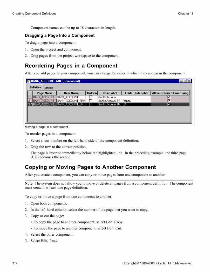
Creating Component Definitions Chapter 11
Component names can be up to 18 characters in length.
Dragging a Page Into a ComponentTo drag a page into a component:
1. Open the project and component.2. Drag pages from the project workspace to the component.
Reordering Pages in a ComponentAfter you add pages to your component, you can change the order in which they appear in the component.
Moving a page in a component
To reorder pages in a component:
1. Select a row number on the left-hand side of the component definition.2. Drag the row to the correct position.The page is inserted immediately below the highlighted line. In the preceding example, the third page(UK) becomes the second.
Copying or Moving Pages to Another ComponentAfter you create a component, you can copy or move pages from one component to another.
Note. The system does not allow you to move or delete all pages from a component definition. The componentmust contain at least one page definition.
To copy or move a page from one component to another:
1. Open both components.2. In the left-hand column, select the number of the page that you want to copy.3. Copy or cut the page:• To copy the page to another component, select Edit, Copy.• To move the page to another component, select Edit, Cut.
4. Select the other component.5. Select Edit, Paste.
314 Copyright © 1988-2006, Oracle. All rights reserved.

Chapter 11 Creating Component Definitions
Setting Page AttributesEach page in a component has attributes. Each attribute is represented by a column in the component definition.
Component item label and tab label
Page Name Displays the read-only name of the page definition. If you rename the page,this column is updated automatically.When creating page definitions, you might want to use similar names tomake them easily recognizable as a group of pages. For example, if youcreate three pages to hold the information for the Personal Data Table, thepage names might be:
• PERSONAL_DATA1• PERSONAL_DATA2• PERSONAL_DATA3
Item Name Displays a name for each page in the component. This name must be uniquein the component, and the default is the page name. This name is forinformational purposes only. If you use the same page on more than onecomponent, you might want to change the item name to reflect the purpose ofthe page in the component.
Hidden Specifies whether the page can be viewed by the user at runtime. Pages areusually hidden when they are used in work groups or associated with derivedwork records. For example, information from a page might need to be loadedinto the buffer for PeopleCode to perform calculations, but the user doesnot need to see it.
Note. Marking the page as hidden also hides the toolbar, including the Savebutton, even if you choose to display the page by means of another method,such as the Transfer PeopleCode function.
Item Label Serves as the default folder tab label, unless a different label is specified. Theitem label should be unique for each page in a single component menu. Thefolder tab label is usually used when shorter names are needed for folder tabs.In the preceding example (BANK_ACCOUNT.GBL), for the first page in thecomponent, the same text appears on both the folder tab and the componentmenu. The second and third pages have different menu names and folder tabs.
Folder Tab Label Displays the text that appears on the folder tab label. If no text is specified, thetext of the item label is used on the folder tabs.
Allow Deferred Processing Indicates whether deferred processing is active for that page in its propertysettings.
Copyright © 1988-2006, Oracle. All rights reserved. 315

Creating Component Definitions Chapter 11
Setting Access KeysYou can set access keys by placing an ampersand (&) in the text of each item label. Put the ampersand in frontof the letter that you want to be underlined on the folder tab at runtime.
Item labels with ampersands (&)
At runtime, the user can navigate between pages by pressing ALT, plus the letter that is underlined, followedby ENTER.
Underlined access keys on tabs
See AlsoChapter 8, “Designing Pages for Optimal Performance and Accessibility,” Using Instructional Text, page 188
Validating ComponentsPeopleSoft Application Designer includes a validate utility to verify the integrity of a component. The validateutility runs a series of tests on components to check that the component will operate properly at runtime andsends the results to the Validate tab in the output window.
To validate a component:
1. Open the desired component definition.2. Select Tools, Options, Validate, and make sure that Validate PeopleSoft Internet Architecture Executionis selected.
Note. This option must be selected for the validate tests to be invoked.
3. Select Tools, Validate Component.4. View the results displayed in the Validate tab, and correct any errors.
See AlsoChapter 2, “Using PeopleSoft Application Designer,” Setting PeopleTools Options, page 20
Chapter 3, “Working With Projects,” Validating Projects, page 56
316 Copyright © 1988-2006, Oracle. All rights reserved.

Chapter 11 Creating Component Definitions
Specifying Market-Specific ComponentsYou might want to add custom features to a component that is specific to an international market or region.For example, suppose that a page is used in a procedure for hiring new employees and that the procedureincludes special transactions that are required only when an employee is hired in Brazil. You can create acustom component using the same component name as the component from which it is derived and saving itusing a market setting of BRA.
Component saved with BRA market setting
Market-specific components are independent of system-side language settings and are accessible to any userwho has security access to the component. This makes it possible for an English-speaking user in New York,for example, to perform a procedure for hiring an employee in Brazil.
Access the market setting of a component using the PeopleCode %Market system variable. Consequently,you can maintain a single set of PeopleCode programs for a set of market-specific components and buildconditional logic into the PeopleCode programs that run only in components that have specific market settings.
See AlsoEnterprise PeopleTools 8.48 PeopleBook: PeopleCode Language Reference, “System Variables,” %Market
Determining Where a Component Is UsedThe Find Definition References feature enables you to generate a list of the menus in the database that referencea specific component; that is, a list of the menus in which the component is used. You can invoke this featurefrom either the project workspace or the workspace. Select Find Definition References from the Edit menu.
See AlsoChapter 2, “Using PeopleSoft Application Designer,” Finding Definitions, page 32
Setting Component PropertiesIn the Component Properties dialog box, specify the update and data entry actions; on the Use tab, specify thesearch record information. You can also save notes about the component on the General tab. Use the Internettab to set attributes that affect how the component appears in the browser at runtime.
Copyright © 1988-2006, Oracle. All rights reserved. 317

Creating Component Definitions Chapter 11
This section discusses how to:
• Open the Component Properties dialog box.
• Set general properties.
• Set use properties.
• Set internet properties.
Opening the Component Properties Dialog BoxTo open the Component Properties dialog box:
1. Open the component definition.2. Select File, Definition Properties.The Component Properties dialog box appears with the General tab active.
Setting General PropertiesAccess the Component Properties dialog box.
Description Enter a descriptive name for the component.
Owner ID Select the application to which this component belongs. This list is helpfulto identify the applications that are associated with the component duringthe application development phase.
Last Updated View the date and time of the last modification made to the component andthe name of the user who made the modification.
Setting Use PropertiesAccess the Component Properties dialog box. Select the Use tab.
318 Copyright © 1988-2006, Oracle. All rights reserved.

Chapter 11 Creating Component Definitions
Component Properties dialog box: Use tab
Access
Search record Specify the search record for this component.
Add search record Specify if you want a different search record specifically for add actions.For example, if you selected the auto-numbering option for employee IDs(EMPLID), don’t include EMPLID in the search record. Likewise, you mightwant to create special security views for add actions that limit the rows thatusers can add, based on specific search criteria. The system default is thestandard search record if you don’t specify an add search record.
Force Search Processing Select to always run search logic (SearchInit PeopleCode) for this component.The default is cleared.
Detail page No longer used in PeopleSoft applications. This option appears for upgradepurposes only.
Copyright © 1988-2006, Oracle. All rights reserved. 319
Creating Component Definitions Chapter 11
Note. To see a subset of search records, type a few characters first. The drop-down list box is populated witha list of all record definitions with names that begin with those characters. This reduces access time andenables you to find specific records faster.
Actions
Add Select to add a new high-level key, such as a new employee ID or customer.Except in the case of effective dating, Add is used to insert a new current rowor to update future rows.
Update/Display Select to update existing rows only.
Update/Display All Select to update current and future rows in an effective-dated record. Useonly with effective-dated records. Do not use these actions unless the mainrecord that is associated with the page definitions is effective-dated. This istranslated to include history at runtime.
Correction Select to update any rows (history, current, and future) in an effective-datedrecord. Use only with effective-dated records. This is translated to correcthistory at runtime.
Disable Saving Page Select when you want to hide the Save button in the toolbar and disable theALT+1 (Save) hot key. This prevents the user from being prompted to savewhen exiting a page. However, it doesn’t prevent using PeopleCode to savea page with the DoSave() or DoSaveNow() functions. This can be helpfulfor applications in which the user isn’t making database changes and doesn’tneed to be prompted to save.
Include in Navigation Select to include the component in the menu navigation at runtime. The defaultis selected. If you do not want the component included, clear the check box.
Mandatory Spell Check Select to ensure that spell check is run on all eligible spell check enabled fieldsin the component when the user saves the page. A field is eligible if it hasbeen changed (or its ReEdit set) and it has not already been manually spellchecked since it was last changed.
Note. If you must add a new high-level key, such as a new employee number or customer, select both Addand Update/Display. If you are adding information to an existing high-level key, such as adding educationdata for an employee, select only Update/Display. You’re not adding a new employee ID—it already existson the database.
Three-Tier Execution LocationThis section applies to Windows client applications only.
To partition application processing between the client and the application server, you must define unitsthat, as a whole, run in one location or the other. We call these units processing groups. Processing groupscan encompass one or more PeopleCode events.
Component Build Specify where you want all processing to occur after the key list of a page isselected and before the user can interact with the page. This includes buildingcomponent buffers and running many types of PeopleCode.
Component Save Specify where you want all processing to occur after the user saves thecomponent and SaveEdit PeopleCode validations have succeeded. It includes
320 Copyright © 1988-2006, Oracle. All rights reserved.
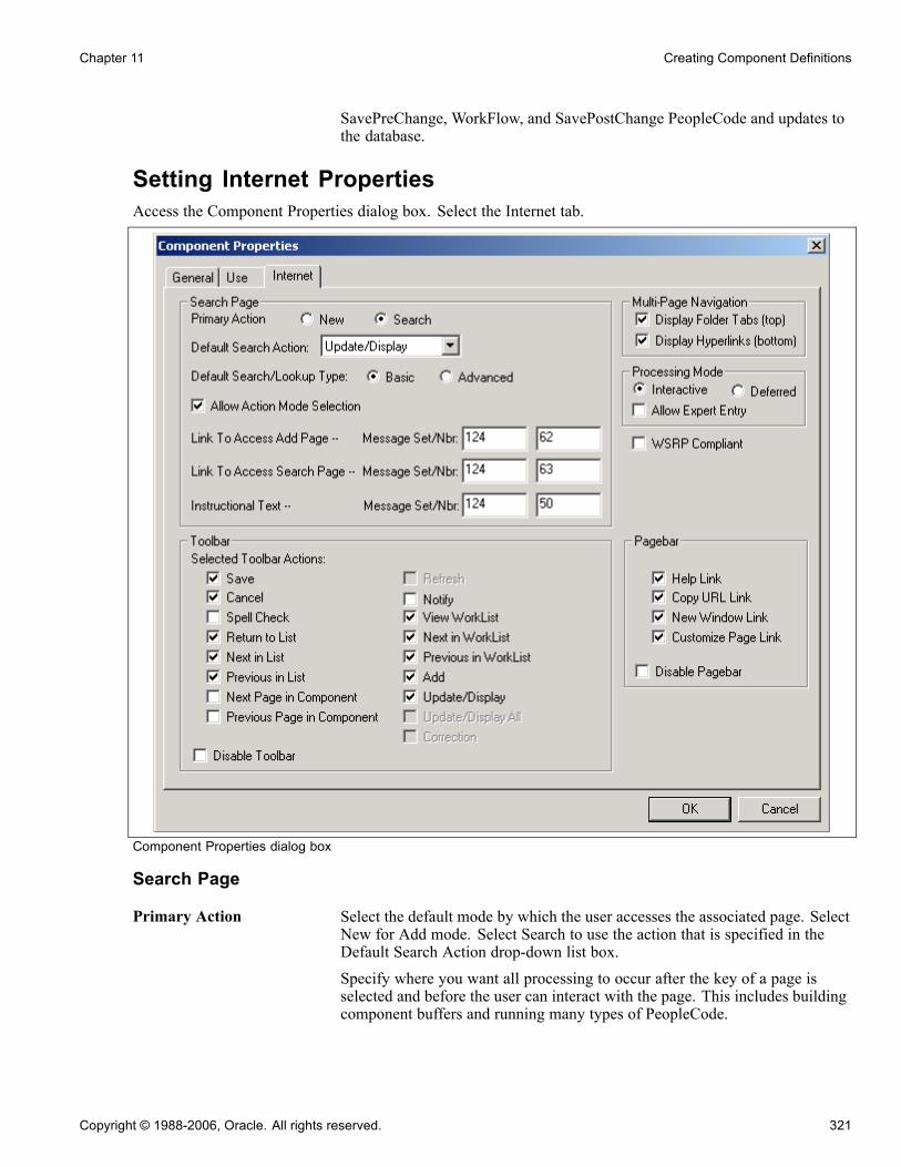
Chapter 11 Creating Component Definitions
SavePreChange, WorkFlow, and SavePostChange PeopleCode and updates tothe database.
Setting Internet PropertiesAccess the Component Properties dialog box. Select the Internet tab.
Component Properties dialog box
Search Page
Primary Action Select the default mode by which the user accesses the associated page. SelectNew for Add mode. Select Search to use the action that is specified in theDefault Search Action drop-down list box.Specify where you want all processing to occur after the key of a page isselected and before the user can interact with the page. This includes buildingcomponent buffers and running many types of PeopleCode.
Copyright © 1988-2006, Oracle. All rights reserved. 321
Creating Component Definitions Chapter 11
Default Search Action Select from a list of the actions that you set in the Actions group box on theUse tab of the Components Properties dialog box. If you set only one action,this drop-down list box provides that choice as the default. The default searchaction determines the default that users see, but they can select anotheroption from the toolbar at runtime.
Default Search/LookupType
Select Basic or Advanced.The basic search page provides a choice of whichfield to search (either the primary and alternate search keys). PeopleSoftrecommends using the basic search page for new users because it is easier tounderstand. If you select Advanced, the advance search page is the default.The search and lookup type applies to the search page and all of the lookuppages in the component.
Allow Action ModeSelection
Select to display the Include History and Correct History check boxes on asearch page. If the user selects Include History on a search page, the pageappears in Update/Display All mode. If the user selects Correct History, thepage appears in Correction mode. However, both of these check boxes appearonly on the search page if Update/Display All and Correction were selectedas actions in the Use properties for the component and the user has securityaccess to the modes. This check box is selected by default.
Link to Access AddPageandLink to AccessSearch Page
Specify the message set and number to display on an Add or Search page.
Instructional Text This is set to display the Find an Existing Value heading on the search page.You can change the default message or redirect the component to use anothermessage that is more appropriate for your use.
ToolbarSelect the toolbar actions that you want to display on the component pages. When you select a check box,that item appears as a toolbar button at the base of the component at runtime. All toolbar actions are set todisplay by default with the exception of Next Page in Component , Previous Page in Component and Notify.Note that the default settings for the Action and Save buttons are impacted by settings on the Use tab ofthe Component Properties dialog box.
Disabling any of the toolbar options also disables the hot key for that option in the PeopleSoft Pure InternetArchitecture.
Save Adds a Save, OK, or Apply button to the toolbar, depending on the page type.
Cancel For modal components only. Clearing this box removes the Cancel buttonfrom the toolbar.
Spell Check Runs spell check for all spell check enabled fields in the component, regardlessof whether any changes have been made to the field.
Return to List Returns user to the search page.
Next in List and Previous inList
Populates the page with the next or previous row of data from the database asshown on the Search page.
Next Page inComponentand PreviousPage in Component
Opens the next or previous page in the component if there is more thanone page.
322 Copyright © 1988-2006, Oracle. All rights reserved.

Chapter 11 Creating Component Definitions
Refresh Redisplays the page without saving any entered data.
Notify Enables the user to send a notification to other users.
View Worklist Enables the user to view the worklist from the current component page.
Next in WorklistandPrevious in Worklist
Enables the user to access the next or previous item in the worklist.
Add, Update/Display,Update/Display All, andCorrection
Select each to enable these toolbar buttons for this component.
See Chapter 11, “Creating Component Definitions,” Setting Use Properties,page 318.
Disable Toolbar Select if you do not want to display the toolbar on the component pages.
Multi-Page Navigation
Display Folder Tabs Select to display folder tabs at the top of the component page.
Display Hyperlinks Select to display links at the bottom of the component page.
Processing Mode
Interactive Select to send messages to the server whenever logic must be run. When theuser presses TAB to exit a field-level event, a transmission to the applicationserver occurs to run that field-level event and the page is refreshed.
Deferred Selected as the default. This mode reduces transmissions to the applicationserver.
See Chapter 8, “Designing Pages for Optimal Performance and Accessibility,”Understanding Processing Modes, page 179.
Allow Expert Entry This is available for both processing modes.
See Chapter 11, “Creating Component Definitions,” Enabling the ExpertEntry Feature, page 326.
WSRP CompliantSelect WSRP Compliant to enable the component for WSRP publishing. If the component is enabled forWSRP publishing the component can be rendered, in-line, within the WSRP consuming portal.
If the component is not enabled for WSRP, when a user navigates to the component from within a WSRPportlet, the system directs the user to the PeopleSoft Portal, which loads the component. That is, the user haseffectively left the WSRP consuming portal page and navigated to the PeopleSoft system.
Note. This option enables you to distinguish between components that are known to function only in thePeopleSoft Portal and those that are WSRP compliant.
See Enterprise PeopleTools 8.48 PeopleBook: Internet Technology, “Understanding Web Services For RemotePortlets (WSRP)”.
Copyright © 1988-2006, Oracle. All rights reserved. 323

Creating Component Definitions Chapter 11
PagebarThe pagebar is a small menu bar that displays at the top of each component page just below the universalnavigation header. You can select which options display to the user for each component. All options areselected by default. Select the Disable Pagebar check box to disable the pagebar altogether.
Help Link Opens the online help PeopleBook entry for the current page.
Copy URL Link Copies the current page URL to the clipboard. The copied URL includes page,action, and search key information to display in the context of the portal, if theuser passed through the portal. If the user did not pass through the portal, thenonly the page displays without the portal frames.This option adds a small http button to the pagebar.
New Window Link Opens a new browser window with the search page for the current component.Users can view or enter data in the new window.
Customize Page Link Opens the Page Customization page which allows the user to control the initialdisplay of the component. This option enables the user to:
• Select the initial page in the component to be displayed.• Save the state of the expanded and collapsed sections.• Save the state of the View All settings on the page for grids and scroll areas.• Customize the page field tabbing order.Users can also elect to copy and share their settings for the component withother users.
Note. If you set this option for a particular component, all users accessingthe component are able to customize the pages in the component unless theirpersonalization options prevent them from customizing pages. Securitypermission list settings or personalization options do not allow the option to beenabled or disabled per end user per component.
See Enterprise PeopleTools 8.48 PeopleBook: Security Administration,“Managing PeopleSoft Personalizations,” Understanding General Options.
See Enterprise PeopleTools 8.48 PeopleBook: Using PeopleSoft Applications,“Setting User Preferences,” Customizing Pages.
You can also enable or disable any of these options using PeopleCode.
See Enterprise PeopleTools 8.48 PeopleBook: PeopleCode API Reference, “Page Class”.
More on the Customize Page OptionIn order for the page customization option to display to the user, in addition to the selection of the PageCustomization Link in the Pagebar, certain criteria must be met:
• A PeopleSoft Pure Internet Architecture page, including search and secondary pages, must be displayedto the user.
• The page cannot be a PeopleTools generated page, such as the Page Customization page or the CustomizeColumn and Sort Order page for grids.
• The current page is not an iScript.
324 Copyright © 1988-2006, Oracle. All rights reserved.

Chapter 11 Creating Component Definitions
• The Customize Pagelink cannot be hidden using PeopleCode for the current component.• The Customize Page Settings, CUSTOMPGSET, personalization option on the Define Personalizationspage must be enabled.This option is enabled by default. If this option is disabled, the end user cannot define, share, or copy pagecustomizations and all existing page customizations for the user are deleted.
• The current page must allow some form of personalization, based on the end users security profile andmeeting at least one of these conditions:- Display more than one page element with a TABINDEX >=1 supporting customization (assume that allcollapsible sections are expanded when determining visibility).
- Contain at least one visible scroll area or grid with a visible View All link, enabled or disabled.- Contains at least one visible collapsible section.
Overriding the Search RecordThis section provides an overview of search records and discusses how to override the search record.
Understanding Search RecordsThe search record controls access to rows of data in a table, and its keys and alternate search keys appear onthe search page as criteria. The search record might also contain logic to refine the search to secure rows ofdata—row-level security is implemented in this way.
The search record field populates the high-level, or level 0, key fields on a page. These key fields usuallyappear above a scroll area or bar or on the page, and they are typically display-only. The search record for acomponent might differ from the primary record definition for a page and might contain any number of searchkeys, but it must contain all of the keys for each main level 0 record for a page.
Note. When you add page items that are based on derived work records, do not select that record definition asthe search record. Instead, select a record definition that stores the primary key or a SQL view that searches forthe criteria that best enables users to identify the rows that they want to retrieve.
If you are configuring menus in an existing PeopleSoft application, the easiest way to decide which searchrecord to use is to look at the other search records that are used on the same menu. Look for pages with similarkey structures and then evaluate the search records to see if any are suitable. You might want to print thePeopleTools Menu Listing cross-reference report (XRFMENU) to review which search records are used forpages and gain a better understanding of how search records are assigned in the application.
Overriding the Search RecordYou might want to reuse a component, changing only its search record.
You can accomplish this by overriding the component search record at the time that the component is invokedfrom a menu. To override a component search record, specify a different search record in the properties of themenu item that invokes the component. The component uses the override search record when it is invokedfrom that specific menu item; the search record set in the component properties remains unchanged.
By reusing components in this way, you can limit redundancy, keeping your application smaller and easierto maintain.
Copyright © 1988-2006, Oracle. All rights reserved. 325

Creating Component Definitions Chapter 11
See AlsoEnterprise PeopleTools 8.48 PeopleBook: PeopleCode Language Reference, “PeopleCode Built-in Functions,”SetSearchDialogBehavior
Accessing the Message CatalogMessage sets and number settings come from the PeopleTools message set catalog.
To access the message catalog:
1. Select PeopleTools, Utilities, Administration, Message Catalog.2. On the search page, enter the message set number that you want to access.Component definitions support messages between 0 and 99,999.
3. Click Search to access a message catalog page.4. Enter the message set and number on the Internet tab of the Component Properties dialog box.For example, enter message set and number 124 and 50 to display the Find an Existing Value message onthe search page in the browser.
Enabling the Expert Entry FeatureThis section provides an overview of the Expert Entry feature and discusses how to enable it in Security.
Understanding Expert EntryExpert entry enables a user to change from interactive to deferred mode at runtime for appropriate transactions.
Note. Expert entry should be used only by expert users of the transaction who understand how all of the fieldsin the transaction behave. It requires the user to know the exact keystroke sequence for the transaction.This sequence typically varies for a transaction by customer, depending on the customer’s setup and entryrequirements. Therefore, expert entry should not be used by occasional users, because they might not be awareof the nuances of the transaction and when it is necessary to press the Refresh hot key.
To use expert entry, select:
• The Allow Expert Entry check box on the Internet tab of the Component Properties dialog box.• The Enable Expert Entry check box in the user’s profile.
If these check boxes are selected, an Expert Entry check box appears on the bottom of the page at runtime.If the user selects this check box, the transaction runs in deferred mode, regardless of the setting on thecomponent, page, or field property.
When you set the component property to deferred mode, that component operates in deferred mode processingfor all users, not just those who have expert entry enabled in their profiles.
If you want the component to process in deferred mode for some users and interactive mode for other users:
326 Copyright © 1988-2006, Oracle. All rights reserved.

Chapter 11 Creating Component Definitions
• Set the component property to Interactive mode.• Select the Allow Expert Entry check box.
This enables security user profiles to control the users for whom deferred mode processing is possible.
Warning! Users who modify component properties from interactive mode to deferred mode or select theAllow Expert Entry check box should understand that this is an adaptation of the software, and, as such, theyare responsible for thoroughly testing and supporting this change.
Refresh ButtonThe Expert Entry feature enables you to specify whether a Refresh button should be included on the componenttoolbar when the page is displayed. The Refresh button forces a transmission to the server to determinewhich fields have changed since the last transmission to the server and to run any processing logic that isassociated with those changes.
Users can also refresh by pressing the ALT+0 hot key, which keeps the cursor in the same field when the pageis refreshed. One can refresh any time during data entry to enable an expert user to:
• Update related display field values for the data that is already entered.• Recalculate totals and balances.• Provide defaults based on prior data that was entered on the page.• Validate the data that has been entered on the page so far.• Invoke the code to hide or gray items associated with specific fields.
Limitations of Expert EntryThese limitations exist when expert entry is enabled:
Hide, Unhide, Gray, andUngray
The user must click the Refresh button after entering a value in a field that isassociated with PeopleCode associated that hides, unhides, grays, or ungraysother fields on the same page.
Drop-down list box The user must click the Refresh button after entering a value in a field that is ahigh-order key that is used to control the values in a drop-down list box.
Default values Whenever expert entry is properly enabled and selected by the user atruntime, the transaction runs in deferred mode. As such, defaults, totals,balances, and related displays are not updated until the next transmission to theapplication sever (for example, when the user clicks a button, icon, link, oranother tab). If the user wants the page updated before then, the user mustclick the Refresh button.
Enabling Expert Entry Through SecurityTo have the Expert Entry check box appear in the component at runtime, the security administrator must enableit in Security. This enables the Expert Entry check box to appear in any components for which you select theAllow Expert Entry property on the Internet tab of the Component Properties dialog box.
To enable expert entry through Security:
1. Sign in to the PeopleSoft system in your browser.2. Select PeopleTools, Security, Use, User Profiles.
Copyright © 1988-2006, Oracle. All rights reserved. 327

Creating Component Definitions Chapter 11
3. Select the General tab.4. Select Enable Expert Entry in the General Attributes group box.5. Click Save.
328 Copyright © 1988-2006, Oracle. All rights reserved.
CHAPTER 12
Creating Menu Definitions
This chapter provides an overview of menus and discusses how to:
• Define custom component menus.• Work with menu definitions.• Define pop-up menus.
Understanding MenusA menu is a logical grouping for assigning security to your system. You create a menu as a placeholder forcomponents. After you save your menu, use the Registration Wizard to assign components and security.
You can create two types of menus using PeopleSoft Application Designer:
• Custom (component) menus provide an internal reference for components and pages. They are groupedlogically into menu groups to assign security. They are not used for navigational purposes.
• Pop-up menus appear when a user clicks a pop-up button.
See AlsoChapter 13, “Using the Registration Wizard,” page 339
Enterprise PeopleTools 8.48 PeopleBook: Security Administration, “Understanding PeopleSoft Security”
Defining Custom Component MenusThis section discusses how to:
• Create custom component menus.• Set menu item properties.• Set general properties.• Set use properties.
Creating Custom Component MenusAfter you create records, pages, and components, register your new component using the Registration Wizard.To do so you must first create a menu definition, if one does not already exist. This enables you to add thecomponent to the new menu (for navigational purposes) and register it in the portal.
Copyright © 1988-2006, Oracle. All rights reserved. 329
Creating Menu Definitions Chapter 12
To create a new menu definition:
1. From the PeopleSoft Application Designer toolbar, select File, New..
2. Select Menu from the list.
3. Click OK.4. Select the Standard option for the menu type.
5. Click OK.The thick rectangle surrounding the bar item indicates that this element in the menu definition is currentlyselected. The empty, dashed rectangle is a placeholder for a new bar item label.
6. Assign a bar name and label.
You can define multiple menu bars for the menu. Double-click the rectangle to display the Bar ItemProperties dialog box.
7. Enter the bar item name and label.
The most commonly used bar item name is Use..
8. Click OK to accept the settings in the Bar Item Properties dialog box.
The new label appears in the menu and the empty rectangle appears in a new location.
9. Set the menu item properties.
When creating a menu simply as a placeholder for components for the Registration Wizard, you need onlyadd a separator bar to save the menu.
10. Set the menu properties.
11. Save the menu definition.
See AlsoChapter 12, “Creating Menu Definitions,” Setting Menu Item Properties, page 330
Chapter 12, “Creating Menu Definitions,” Setting General Properties, page 331
Chapter 13, “Using the Registration Wizard,” page 339
Chapter 2, “Using PeopleSoft Application Designer,” Saving Definitions, page 29
Setting Menu Item PropertiesSet the menu item properties to define your menu item. When creating a new menu definition to be used in theRegistration Wizard, you need only select Separator from the Type area of the Menu Item Properties dialogbox. This enables you to save the menu definition for use in the Registration Wizard. If you decide not touse the Registration Wizard you need to perform the entire following procedure and set the general anduse properties for the menu definition.
To define a menu item:
1. In a standard menu definition, double-click a menu item to access its properties.To create a new menu item, double-click the empty rectangle at the bottom of the menu.
2. Specify the menu item.
Name Specify the system name for the menu or menu item. Menu and menuitem names must conform to a specific set of naming conventions for the
330 Copyright © 1988-2006, Oracle. All rights reserved.

Chapter 12 Creating Menu Definitions
system to recognize them: all uppercase letters, no embedded spaces, andno special characters (for example, %, ^, &, *, $, #).
Label Specify the text label to appear on the menu. The label appears in theHome bar item or in a cascade menu of a menu group. You can place anampersand in the text to assign a keyboard shortcut for the menu.
3. Select the menu item type.
Component Select for a standard component menu item.
PeopleCode PeopleCode menu items trigger PeopleCode programs. The programruns in a component buffer context, which allows PeopleCode to accessvalues in the component buffer.
Separator Select this option when creating a menu for the Registration Wizard.Selecting this option disables all other fields in the Menu Item Propertiesdialog box.
4. Click the Select button.
5. Select an enabling component in the Open dialog box.
At runtime standard PeopleCode menu items are always visible in a menu, but they are active (enabled)only when their enabling components are open.
6. Save the menu item if it has not yet been saved.
7. In the menu definition, right-click the menu item, then select View PeopleCode.
The PeopleCode editor appears.
8. Add a PeopleCode program in the menu item’s ItemSelected event.
9. When you have finished typing the program, save the PeopleCode program and close the PeopleCode editor.
10. (Optional) Override the component search record.
You might want to reuse the same component multiple times with different search records. You canaccomplish this by overriding the component search record at runtime when the component is opened froma menu item without creating separate copies of the component. The component override is temporary,and occurs only when the component is opened from the menu item in which the override is set. It doesnot change the component definition.
Select the Override check box, then select an override search record from the Override prompt field. Theoverride search record must be a valid search record for the component; that is, it must have all of thesearch key fields that are at level 0 of the component pages.
11. Click OK to accept the settings.
12. Save the menu definition.
Setting General PropertiesWhen you create or make changes to a menu, it’s a good idea to document it for future reference. You can dothis on the General tab of the Menu Properties dialog box.
Description Enter a descriptive name for the menu.
Comments Add a description of the menu or any other useful information.
Copyright © 1988-2006, Oracle. All rights reserved. 331

Creating Menu Definitions Chapter 12
Owner ID View a list of applications with which this menu is used. This list is helpful toidentify the applications with which the menu is associated during applicationdevelopment.
Last Updated View the date and time of the last modification and the name of the userwho made the modification.
Setting Use PropertiesSetting properties on the Use tab of Menu Properties is optional. Any settings you assign are stored internallyonly.
Working With Existing Menu DefinitionsPeopleSoft recommends that you do not modify PeopleTools menus, but that you create your own custommenu.
This section discusses how to:
• Add components to a menu.
• Rename menu definitions.
• Copy a menu definition.
• Delete menu items.
• Print menu definitions.
• Set up menu security.
• Import menu groups into portals.
Adding Components to a MenuUse the Registration Wizard to add your component to a menu.
See Chapter 13, “Using the Registration Wizard,” page 339.
Renaming Menu DefinitionsWhen you change the name of the menu definition, you do not change the name of the application window thatappears when you select the new menu from the PeopleSoft application.
To rename a menu definition:
1. Close all open definitions in the definition workspace.
2. Select File, Rename.
The Rename Definition dialog box appears.
3. Select Menu from the Definition Type drop-down list box.
4. Click Rename.
5. From the list of available menus, double-click the menu that you want to rename.
332 Copyright © 1988-2006, Oracle. All rights reserved.

Chapter 12 Creating Menu Definitions
6. Type the new name over the name that is selected on the menu definition.7. Click Rename.
Note. If you rename a menu definition, be sure to rename the corresponding registry entries manually.
See AlsoChapter 2, “Using PeopleSoft Application Designer,” Saving Definitions, page 29
Copying a Menu DefinitionCreating a copy of a menu definition is different from renaming the definition. The Save As command createsa copy of the definition with a new name while keeping the old menu definition unchanged.
To copy a menu definition:
1. Open the menu definition that you want to copy.2. Select File, Save As.The Save As dialog box appears.
3. Type a new name for the copy of the menu definition.4. Click OK.You are prompted to save a copy of any PeopleCode that you have associated with the menu definition.
Deleting Menu ItemsDelete an item to remove it permanently from a menu definition. To help prevent accidental deletions, you candelete only one entry at a time.
To delete a menu item:
1. Select the menu item that you want to delete.
2. Select Edit, Clear.
If you attempt to delete a menu item that is linked to PeopleCode, the system issues a warning.
If you proceed to delete it, the linked PeopleCode menu items are also deleted.
If you delete an item by mistake, before you perform any additional edits or saves, select Edit, Undo torestore the menu item.
Note. When deleting menu items, remember to delete any corresponding registry entries.
Printing Menu DefinitionsIn addition to printing a menu definition from the definition workspace, you can obtain a formatted report of allmenu definitions by printing the PeopleTools Menu Listing cross-reference report (XRFMENU). This reportlists application windows in alphabetical order and details all menus in each window and all page definitions ineach menu. It also includes the associated search record definition name and detail page definition name.
To print a menu definition:
1. Open the menu definition that you want to print so that it appears in the definition workspace as thecurrent definition.
Copyright © 1988-2006, Oracle. All rights reserved. 333
Creating Menu Definitions Chapter 12
2. Select File, Print.The standard Windows Print dialog box appears.
Setting Up Menu SecurityWhenever you make a change or add items to an existing custom menu definition, you might need to adjustyour security settings. When you add a new menu to a security profile, that menu is available the next time thatyou sign in to the system. Use the Registration Wizard to assign security.
See AlsoChapter 13, “Using the Registration Wizard,” page 339
Enterprise PeopleTools 8.48 PeopleBook: Security Administration, “Understanding PeopleSoft Security”
Importing Custom Menu Groups Into PortalsThe menu import process creates content references for all components and pages that belong to the menugroup. This should be used to migrate custom menus only.
See AlsoEnterprise PeopleTools 8.48 PeopleBook: Internet Technology, “Configuring the Portal Environment,”Importing Menu Groups into the Portal Registry
Defining Pop-up MenusThis section provides an overview of pop-up menus and discusses how to:
• Create pop-up menus.• Define transfer menu items.
Understanding Pop-up MenusPop-up menus define the transition to another page—either a system-defined page containing a set ofstandard commands or a pop-up menu page that was created and associated with the pop-up button by anapplication developer.
You can also use pop-up menus to run a PeopleCode program. PeopleCode in pop-up menus does not sharethe same limitations as PeopleCode in standard menus, so pop-up transition menus provide an effectivealternative to using command push buttons on pages. Pop-up menu PeopleCode programs can be used forany number of purposes, for example:
• To perform a modal transfer.• To recalculate a field value.• To trigger a PeopleSoft Workflow business event.
Behavior of Pop-up Menus in PagesThese standard icons appear on the page at runtime when a pop-up menu is defined for a page field:
334 Copyright © 1988-2006, Oracle. All rights reserved.

Chapter 12 Creating Menu Definitions
When a user clicks the pop-up icon (PT_POPUP) on a page, a screen appearswith a list of menu items from which to select.
This pop-up icon (PT_POPUP_SKIP) appears if a pop-up menu has onlyone menu item. When a user clicks this icon, the target transaction pageappears immediately, skipping an intermediate page containing a list withone menu item.
For example, the Annual Benefits Base Rate field on the following page contains a pop-up icon, whichopens the Display in Other Currency page.
Pop-up button on a page
This type of transfer to another component is called a definitional transfer to distinguish it from transfers thatare made using PeopleCode programs. Definitional transfers are always nonmodal. To run a modal transfer,you must use PeopleCode.
Creating Pop-up MenusThis section discusses how to:
• Create a new pop-up menu.• Associate a pop-up menu with a page field.
Creating a New Pop-up MenuTo create a new pop-up menu:
1. Select File, New.The New dialog box appears.
2. Select Menu.3. Click OK.The New Menu dialog box appears.
Copyright © 1988-2006, Oracle. All rights reserved. 335

Creating Menu Definitions Chapter 12
4. Select the Popup option for the menu type.5. Click OK.A new pop-up menu definition appears.
6. Define the menu items for the pop-up menu.7. Set the menu properties.
a. Add a description and comments about your pop-up menu.b. On the Use tab, type the menu label that you want to appear for that pop-up.
8. Save the pop-up menu definition.9. To provide users with access to the pop-up menu, associate it with a page field.
Associating a Pop-up Menu With a Page FieldTo associate a pop-up menu with a page field:
1. Open the page definition that contains the page field to which you want to associate the pop-up menu.2. Right-click the page field, then select Page Field Properties.3. When the properties dialog box for that field appears, select the Use tab.4. In the Popup Menu group box, select from the available pop-up menus in the drop-down list box.5. Click OK.6. Save the page definition.
See AlsoChapter 12, “Creating Menu Definitions,” Setting Menu Item Properties, page 330
Defining Transfer Menu ItemsTransfer menu items, which can be created only in pop-up menus, enable you to specify a menu, component,and page to which the user is taken when the transfer menu item is selected. The following procedure describeshow to create a new transfer menu item or redefine an existing menu item as a transfer menu item.
To define a transfer menu item:
1. In a pop-up menu definition, double-click a menu item to access its properties.To create a menu item, double-click the empty rectangle at the bottom of the menu. This displays theMenu Item Properties dialog box for pop-up menus.
2. If this is a new menu item, enter a menu item name and label text in the Menu Item fields.You can create a shortcut key for the menu item by placing an ampersand in the label.
3. Set the transfer properties.• Click the Transfer button to make this a transfer menu item.• Click the Define Transfer button to display the Transfer Properties dialog box.This dialog box enables you to define the properties of a definitional transfer that is made from a pop-upmenu item. The component from which you are transferring is called the originating component. Thecomponent to which you are transferring is called the destination component.
4. Specify the following:
336 Copyright © 1988-2006, Oracle. All rights reserved.

Chapter 12 Creating Menu Definitions
Portal Select the navigation registry, such as employee portal.
Node Select the PeopleSoft database to which you want the transfer menu topoint. Local is the default. Valid values include all of the values in theMSGNODENAME column of the PSMSGNODEDEFN table. If youselect a node other than Local, the system clears the Use data from currentpage in search dialog check box.
Menu Select the name of the menu containing the destination component.
Component Select the name of the destination component.
Market Select the market of the destination component.
Component Item Select the name of the page to display at the front of the destinationcomponent.
Action Select an action mode (Update/Display, Update/Display All, Correction, orData Entry) to constrain the user profile to a specific action mode at thetime of the transfer. The action modes that are available in the promptlist depend on which modes are specified as valid in the destinationcomponent definition.Select Prompt to enable the user profile to select an available actionmode at the time of the transfer. The action modes that the user profilecan select depend on which action modes are defined as valid in thedestination component definition and to which action modes the userprofile is granted access in Maintain Security.
5. Set the transfer type.
Re-use current window Select to transfer to the component in the same window in which thetransfer is initiated.
Use new window (minimizecurrent window)
Select to minimize the current window and open the destination componentin a separate window.
6. Specify whether to supply search key values from the originating component.
Use data from current pagein search dialog
Select to use the values from the originating component search keys in thesearch dialog box of the destination component. If these values allow thesystem to select a unique row from the search record, the search dialog boxis bypassed and the destination component opens immediately.Clear this check box if you want the user to type the search key valuesinto the search dialog box.
7. Click OK to accept the Transfer Properties dialog box settings.8. Click OK to accept the Menu Item Properties dialog box settings.9. Save the menu definition.
Copyright © 1988-2006, Oracle. All rights reserved. 337

Creating Menu Definitions Chapter 12
338 Copyright © 1988-2006, Oracle. All rights reserved.
CHAPTER 13
Using the Registration Wizard
This chapter provides an overview of the Registration Wizard and describes how to:
• Register a component or iScript.• Register the component in multiple portals.• Register a mobile page.
Understanding the Registration WizardThis section lists common elements and discusses the Registration Wizard.
Common Elements Used in This Chaptercontent reference A reference to a URL (Uniform Resource Locator) for a transaction page.
Appears as a link in the navigation menu at runtime.
iScript A specialized PeopleCode function that generates dynamic web content.
See Enterprise PeopleTools 8.48 PeopleBook: PeopleCode API Reference,“Internet Script Classes (iScript)”.
permission list A set of access rights to application objects, including processes and reports,weblib functions, and other elements.
See Enterprise PeopleTools 8.48 PeopleBook: Security Administration,“Setting Up Permission Lists”.
portal registry A tree structure in which content for a portal is organized, classified, andregistered. A portal registry consists of folders, content references, and nodes.
See Enterprise PeopleTools 8.48 PeopleBook: Internet Technology,“Understanding Portal Technology,” Portal Registry.
Working With the Registration WizardAfter you create your pages and assign them to a component, you can register that component to display thetransaction page in the browser. You can do this using the Registration Wizard. The wizard gathers information,then attaches the component to a menu, assigns a permission list to allow security access rights, and places acontent reference entry in the portal registry, which displays the component to the user on the navigation menu.
Copyright © 1988-2006, Oracle. All rights reserved. 339

Using the Registration Wizard Chapter 13
Note. Before running the Registration Wizard, the menu definition, permission list, and folder must exist.The wizard does not create these definitions. Instead it matches existing definitions to one another andcreates the content reference.
Registering a Component or iScriptIn Application Designer, open the component definition that you want to register. If you are creating a newcomponent, make sure that you save it before opening the Registration Wizard. For iScripts, open the recorddefinition that holds the iScript function. By convention, such records begin with the WEBLIB_ prefix.
You can access the Registration Wizard using any of these methods:
Click the Register Component or Register iScript icon in the toolbar
Pop-up menu Select Register Component from the pop-up menu after right clickingon the component.
Tools menu Select Register Component or Register iScript from the Tools menu.
Note. All settings in the Registration Wizard default to those referenced in the previous wizard session.
The Create Content Reference screen of the Registration Wizard enables you to assign the component to aportal and assign a content reference name.
340 Copyright © 1988-2006, Oracle. All rights reserved.
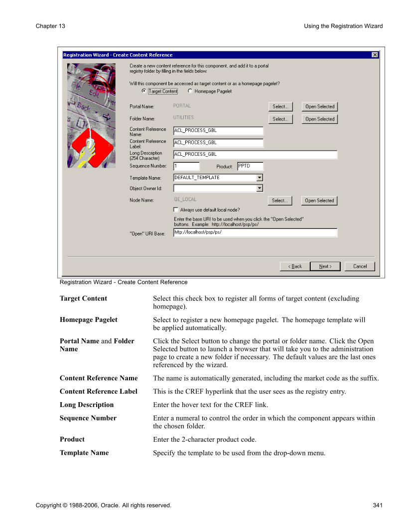
Chapter 13 Using the Registration Wizard
Registration Wizard - Create Content Reference
Target Content Select this check box to register all forms of target content (excludinghomepage).
Homepage Pagelet Select to register a new homepage pagelet. The homepage template willbe applied automatically.
Portal Name and FolderName
Click the Select button to change the portal or folder name. Click the OpenSelected button to launch a browser that will take you to the administrationpage to create a new folder if necessary. The default values are the last onesreferenced by the wizard.
Content Reference Name The name is automatically generated, including the market code as the suffix.
Content Reference Label This is the CREF hyperlink that the user sees as the registry entry.
Long Description Enter the hover text for the CREF link.
Sequence Number Enter a numeral to control the order in which the component appears withinthe chosen folder.
Product Enter the 2-character product code.
Template Name Specify the template to be used from the drop-down menu.
Copyright © 1988-2006, Oracle. All rights reserved. 341

Using the Registration Wizard Chapter 13
If you specified that the target content should be accessed as a homepagepagelet, then this field will not be displayed, and the homepage template willbe applied automatically.
Object Owner Id Select the application development group that owns the object.
Node Name Click Select to change the Node name, or click the Open Selected button tolaunch the administration page to view the properties of the node.
Always use default localnode
Select to always override the selected node name with the specified defaultlocal node.
"Open" URI Base Enter the Universal Resource Identifier (URI) that specifies for PeopleSoftApplication Designer the location of your PeopleSoft Pure InternetArchitecture site. This is for informational purposes only. It is used only forthe Open Selected button and not stored to the database.If you entered a base URI on the Browser tab of the Options dialog box, thatvalue displays in this field.The URI you enter in this field is reflected on the remaining pages of theRegistration Wizard. If you make a change to this field on any page, thechange is reflected throughout.
To register a component or iScript:
1. Open the component or iScript you want to register.You can also launch the Registration Wizard from the menu definition by right clicking on a menu itemthat points to a component.
2. Open the Registration Wizard.Select Tools, Register in Portal or click the icon on the Toolbar.The Start screen of the Registration Wizard gives the option of adding the component to a menu, a portalregistry, and/or a permission list. If this is a new component and the first time that you are running thewizard, you should select all three options. If you have already run the wizard on this particular componentand just need to add it to an additional permission list or portal, deselect the other options.
Add this component toa menu
Select to add the component to a menu. You must create the menudefinition first if it does not already exist. You specify the menu onthe following screen of the Registration Wizard. If you do not selectthis option, you will need to add the component to the menu manuallyusing the Menu designer.
See Chapter 12, “Creating Menu Definitions,” Creating CustomComponent Menus, page 329.
Add this component to aportal registry
Select if you want to create a content reference for the component andadds it to the portal registry you specify on the Create Content Referencescreen of the Registration Wizard.
Add this component to apermission list
Select if you want to specify the permission list on the final screen ofthe Registration Wizard.
If this is a new component or iScript and the first time that you’ve run the Registration Wizard, you willmost likely want all three options selected. If you are rerunning the wizard to simply add the component toan additional permission list or another portal, you would clear the other options.
342 Copyright © 1988-2006, Oracle. All rights reserved.

Chapter 13 Using the Registration Wizard
The wizard remembers the selection that you made the last time that you ran the wizard and selectsthose values by default.
3. Click Next.If you selected to add the component to a menu, the next screen, Add to Menu and Bar, opens.
4. Click the Select button to find the menu name and the drop-down list box to assign the bar name, thenclick Next.These names are not exposed to users, but are required for internal location purposes. Click the OpenSelectedbutton to open the menu that you selected in Application Designer. To view the menu definitionwithout closing the wizard, drag the Registration Wizard to the side.
5. On the Create Content Reference screen, select Target Content or Homepage Pagelet.If the component is a standard transaction, register it as Target Content.
6. Complete all fields in the Create Content Reference screen and click Next.7. Click the Select button to find your menu name, then use the drop-down list box to select the namethat displays on the bar.Menus are used as logical groupings to which you can apply security, PeopleSoft components areaddressed by menu name (the URL includes the menu name). To add this component to a menu, specifythe menu name and bar name.If you did not select the Add this component to a menucheck box on the Prompt page, this page displaysthe menu name and the Select button only. You then must select the correct menu that already containsthe component.If you are working with an iScript, you must select the iScript function to register.
8. Click Next.9. Select Target Content if your component is a standard transaction and complete the appropriate fields.The previous term table defines each of these fields.If you did not select Add this Component to a Portal Registry on the Prompt page, this page does not display.
10. Click Next.11. Select the appropriate permission list, select all the actions that you want to grant this component oriScript, and enter the base URI.Use the Select button to view and select a permission list.If you did not select Add this Component to a Permission List, this page does not display.
12. Click Next.13. Review the selections made so far. If you need to change anything, use the Back button to edit your entries.Select the options in the Add to project area to place your item into an active PeopleTools project. This iscumulative behavior—the more times you run the wizard while the project is active, the more menus,registry structures, and permission lists are added to that project.
14. Click Finish to complete the registry process into the specified portal.If you click Cancel all of the entries that you have made in the wizard will be lost and no changes willbe made.
Copyright © 1988-2006, Oracle. All rights reserved. 343
Using the Registration Wizard Chapter 13
See AlsoChapter 12, “Creating Menu Definitions,” page 329
Enterprise PeopleTools 8.48 PeopleBook: Security Administration, “Setting Up Permission Lists”
Registering a Component in Multiple PortalsAfter you have used the Registration Wizard to register your new component into the portal you may need toregister the component in other portals also.
There are two ways to do this.
• You can use the Portal Registration Wizard again. Select only the second option: Add this component to aportal registry. Then reenter the content reference label, long description, and sequence number (if not 1) tomatch the other portal’s entry.
• You can just copy the component to other portals from portal Administration pages in the web client.
See Enterprise PeopleTools 8.48 PeopleBook: Internet Technology.
Registering a Mobile PageAs with a component or iScript, you can also register a mobile page in the portal using the RegistrationWizard, though the wizard is slightly different. This wizard always assigns the mobile page to the MOBILEportal and does not require a node name.
344 Copyright © 1988-2006, Oracle. All rights reserved.
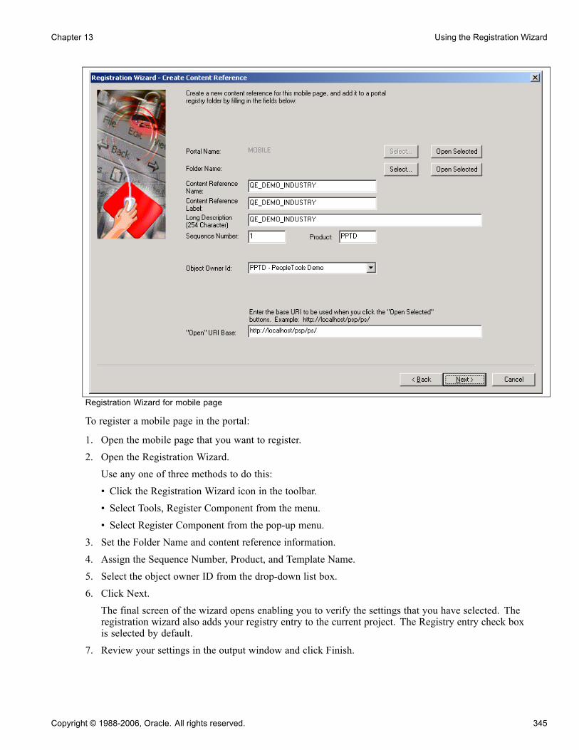
Chapter 13 Using the Registration Wizard
Registration Wizard for mobile page
To register a mobile page in the portal:
1. Open the mobile page that you want to register.2. Open the Registration Wizard.Use any one of three methods to do this:• Click the Registration Wizard icon in the toolbar.• Select Tools, Register Component from the menu.• Select Register Component from the pop-up menu.
3. Set the Folder Name and content reference information.4. Assign the Sequence Number, Product, and Template Name.5. Select the object owner ID from the drop-down list box.6. Click Next.The final screen of the wizard opens enabling you to verify the settings that you have selected. Theregistration wizard also adds your registry entry to the current project. The Registry entry check boxis selected by default.
7. Review your settings in the output window and click Finish.
Copyright © 1988-2006, Oracle. All rights reserved. 345

Using the Registration Wizard Chapter 13
See AlsoEnterprise PeopleTools 8.48 PeopleBook: PeopleSoft Mobile Agent, “Creating Mobile Pages”
346 Copyright © 1988-2006, Oracle. All rights reserved.

CHAPTER 14
Creating Style Sheet Definitions
This chapter provides an overview of style sheets and classes and discusses how to:
• Create style sheets.• Add a new class.• Set class attributes.• Change the default style sheet for an application.• Specify a style sheet for a page.• Change colors on tabs.
Understanding Style Sheets and ClassesThis section discusses:
• Types of classes.• PSSTYLEDEF
The default styles that PeopleSoft ships with your product come from style sheets. A style sheet is a definition,like a record or field definition, that you create in PeopleSoft Application Designer. It is a collection offormatting styles, each of which can be applied to page controls. A style sheet is a standalone definitionthat can be upgraded, deleted, renamed, and so on.
Style sheets are useful because they enable developers to change the formatting of many page attributesacross multiple pages quickly and easily.
Sub Style SheetsIn the same way that PeopleTools supports subrecords, you can define sub style sheets to share a common setof classes. A sub style sheet has all of the properties of a style sheet.
Types of ClassesEach style sheet comprises individual classes that affect the formatting of each page control. Classes control abroad range of characteristics, including font size, spacing, alignment, border width, weight, and color.
Style sheets have two different types of classes: default and custom. When you create a new style sheet, aseries of default classes is included in the definition.
Note. If you change a style attribute for any default classes, you change every occurrence of that controlthroughout an application (unless that control is overridden in the page field properties dialog box).
Copyright © 1988-2006, Oracle. All rights reserved. 347

Creating Style Sheet Definitions Chapter 14
Default ClassesEach type of page control specifies an explicit default class. If the Style drop-down list box of a page elementshows Use Default Style, the default class controls the formatting of that element on that page. You canoverride these classes by using the properties dialog box for each specific control.
Custom ClassesIndividual page controls do not have to be associated with the default class. By creating new custom classesand overriding the default style, you can have unique pages in an application.
When you select the Style drop-down list box in the properties dialog box for the page control, all of the classesin the style sheet for that page appear.
Edit Box Properties dialog box showing style classes
Overriding Page Styles in a FieldMany page field controls have a style field in their field properties. Using this field property, you can specify astyle class other than the default. You can also specify a different style class for a field at runtime using theStyle property in PeopleCode.
348 Copyright © 1988-2006, Oracle. All rights reserved.

Chapter 14 Creating Style Sheet Definitions
Note. You can specify only a single style sheet for a page or an application. You can specify different styleclasses within that style sheet for a control. You cannot specify a page-field control class from a style sheet thatis not associated with the page.
Depending on the page control, you can assign a style sheet class to either the label or the control itself.For example, for an edit box, you can specify the color that appears in the edit box and the color of thelabel and its text.
Example of Style Class Assigned at RuntimeTo set a style class to a field at runtime, use PeopleCode to define the Style property for a field definition. Thisexample sets a different style class to a field, depending on the value of the field:
Local Field &field;
&field = GetField();
If TESTFIELD1 = 1 Then;
&field.Style = "PSHYPERLINK";
End-If;
If TESTFIELD1 = 2 Then;
&field.Style = "PSIMAGE";
End-If;
Example of a field with PSHYPERLINK style applied
Example of a field with PSIMAGE style applied
See AlsoEnterprise PeopleTools 8.48 PeopleBook: PeopleCode API Reference, “Chart Class,” Style Sheets and Charts
PSSTYLEDEFPSSTYLEDEF is the default style sheet that is delivered with your PeopleTools software and consists ofthese sub style sheets:
• PSALTERNATE: Defines application alternatives to PS defaults.• PAALTERNATE: Defines PeopleSoft Portal Solutions alternatives to PS defaults.• PTSTYLEDEF: Defines the standard PeopleSoft Pure Internet Architecture and portal defaults.
If you want to change the style sheet, in the PeopleSoft Pure Internet Architecture select PeopleTools, Utilities,Administration, PeopleTools Options; then, select the desired style sheet in the Style Sheet Name field.
You can also change the sub style sheets associated with a style sheet.
See Chapter 14, “Creating Style Sheet Definitions,” Inserting a Sub Style Sheet, page 350.
Copyright © 1988-2006, Oracle. All rights reserved. 349

Creating Style Sheet Definitions Chapter 14
See AlsoAppendix C, “Using Default Style Classes,” page 543
Creating Style SheetsThis section discusses how to:
• Create a new style sheet or sub style sheet.• Insert a sub style sheet into a style sheet.
Creating a New Style SheetTo create a new style sheet or sub style sheet:
1. Select File, New.2. Select Style Sheet from the list.When you create a new style sheet, the system sets the parent to be the style sheet listed in the PeopleToolsOptions page (default is PSSTYLEDEF).
3. Select File, Definition Properties.The Style Sheet Properties dialog box appears.
4. Specify the style sheet options.
Standard Style Sheet andSub Style Sheet
Select the type of style sheet. Use sub style sheets as you would usesubrecords or subpages.
Parent Style Sheet If this is a standard style sheet, the default style sheet (PSSTYLEDEF)is the parent.
Inserting a Sub Style SheetTo insert a sub style sheet into a style sheet:
1. Create or open a style sheet.2. Select Insert, Insert Sub Style Sheet.3. In the drop-down list box, select the sub style sheet that you want to insert into the style sheet.4. Click OK.If you are replacing sub style sheets, you can delete the existing ones from the style sheet by highlightingthe sub style sheet and pressing DELETE.
Adding a New ClassYou can add a new style class to a style sheet and use it like any other class.
To add a new class:
350 Copyright © 1988-2006, Oracle. All rights reserved.

Chapter 14 Creating Style Sheet Definitions
1. Open (or create) the style sheet to which you want to add a class.2. Select Insert, Insert Style Class from the PeopleSoft Application Designer menu.3. Enter the name of the new class.4. To copy the class attribute from another style class, select that class from the Copy Values From StyleClass drop-down list box.
5. Click OK.
Note. For efficiency, it is common to clone style classes from other style sheets and insert them into other stylesheets using the Insert menu or a copy/paste. However, consider that when copying style classes, the copy orclone will not contain any of the related language data associated with the original.
Setting Class AttributesThis section provides overviews of class attributes and fonts and discusses how to:
• Access class attributes.• Specify fonts.• Set font attributes for a specific language.• Specify spacing and alignment.• Specify background attributes.• Reference a background image URL.• Specify border attributes.• Specify margins.• Specify miscellaneous attributes.
Understanding Class AttributesClass attributes are grouped into categories and are displayed in a tabbed dialog box for each class.
Note. PeopleSoft Application Designer does not always reflect the formatting attributes that are specified for acontrol. You might be able to see only one attribute at runtime. Also, not all browsers support every attribute.
PeopleSoft Pure Internet Architecture supports the attributes that are listed in the World Wide Web Consortium(W3), Cascading Style Sheets, Level 1.
See http://www.w3.org/TR/REC-CSS1
Every class has each of these major attributes, which correspond to a tab in the Class Attribute definition.
Font Controls the font in which text appears. If more than one font is specified, thebrowser displays the first font; if it cannot find it, it displays the next font.
Spacing/Alignment Controls the spacing in addition to the default spacing. You can specifyadditional spacing between words and between letters. You can also specifythe alignment, height, indent, and white space.
Copyright © 1988-2006, Oracle. All rights reserved. 351

Creating Style Sheet Definitions Chapter 14
Background Controls the background colors for the page control. If the background isan image, you can select how the image appears.
Border Controls the border that is displayed around the element. You can specifywidth, color, and style.
Margins Controls the margins and padding on each side of the element.
Miscellaneous Controls the display of list-item markers, URLs, and cursor formats.
Understanding Generic and Installed FontsWhen you add a font, the dialog box provides a choice between generic fonts and installed fonts.
Generic fonts can be displayed on all browsers. This table displays examples of some of the generic fonts:
Generic Font Example
Cursive Zapf-Chancery
Fantasy Western
Monospace Courier
Sans serif Helvetica
Serif Times Roman
Installed FontsInstalled fonts are installed on your computer. If you use an installed font for a style class, PeopleSoftrecommends that you:
• Verify that all users of your application have the same installed font.• Specify the installed font first, followed by a generic font.This way, if the installed font is not available to the user of your application, the generic font can be used.
Accessing Class AttributesTo access class attributes:
1. Open a style sheet.a. Select File, Open, Style Sheet.b. Select the style sheet that you want to access from the Definition Type drop-down list box
2. Double-click the class name.
Specifying FontsAccess the class dialog box. Select the Font tab.
352 Copyright © 1988-2006, Oracle. All rights reserved.
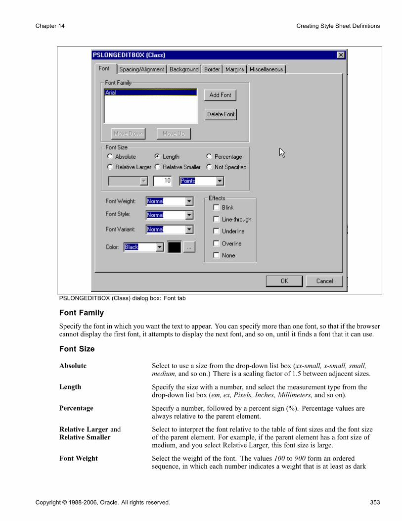
Chapter 14 Creating Style Sheet Definitions
PSLONGEDITBOX (Class) dialog box: Font tab
Font FamilySpecify the font in which you want the text to appear. You can specify more than one font, so that if the browsercannot display the first font, it attempts to display the next font, and so on, until it finds a font that it can use.
Font Size
Absolute Select to use a size from the drop-down list box (xx-small, x-small, small,medium, and so on.) There is a scaling factor of 1.5 between adjacent sizes.
Length Specify the size with a number, and select the measurement type from thedrop-down list box (em, ex, Pixels, Inches, Millimeters, and so on).
Percentage Specify a number, followed by a percent sign (%). Percentage values arealways relative to the parent element.
Relative Larger andRelative Smaller
Select to interpret the font relative to the table of font sizes and the font sizeof the parent element. For example, if the parent element has a font size ofmedium, and you select Relative Larger, this font size is large.
Font Weight Select the weight of the font. The values 100 to 900 form an orderedsequence, in which each number indicates a weight that is at least as dark
Copyright © 1988-2006, Oracle. All rights reserved. 353
Creating Style Sheet Definitions Chapter 14
as its predecessor. The value Normal is synonymous with 400, and Boldis synonymous with 700.
Font Style Select the style of the font. Values are: Normal, Italic, or Oblique. Theseare matched to existing fonts with those names.
Font Variant Select a variant. Values are: Normal or Small Caps. In a small caps font, thelowercase letters look similar to the uppercase ones, but they’re in a smallersize and with slightly different proportions.
Color Specify the color or select the color from a color palette.
Setting Font Attributes for a Specific LanguageYou can change the fonts that are available based on the base language settings. The default for the baselanguage is English, providing generic fonts. If these fonts are not appropriate for a particular language, youmust set the language preference before opening a style sheet. You can then set the font name list, font size, orfont weight for the selected language.
To set font attributes for a specific language:
1. Select PeopleTools, Utilities, International, Preferences from your browser.2. Select the appropriate language for the style sheet from the drop-down list box.3. Save the new selected language as the base language.4. Open the style sheet definition in which you want to save the font name list, font size, or font weight forthe selected language.
Specifying Spacing and AlignmentAccess the class dialog box. Select the Spacing/Alignment tab.
354 Copyright © 1988-2006, Oracle. All rights reserved.

Chapter 14 Creating Style Sheet Definitions
PSEDITBOX (Class) dialog box: Spacing/Alignment tab
Word Spacing and LetterSpacing
Select Normal or Length. If you select Length, specify a number to indicate anaddition to the default space between words or letters. Values can be negative,but there might be implementation-specific limits.
Vertical Alignment Select the vertical positioning of the element. Values are:Baseline: Aligns the baseline of the element (or the bottom, if the elementdoesn’t have a baseline) with the baseline of the parent.Sub: (subscript) Aligns the top of the element with the baseline of the parentelement.Super: (superscript) Aligns the baseline of the element with the top of theparent element.Top: Aligns the top of the element with the tallest element on the line.Text Top: Aligns the top of the element with the top of the parent elements font.Middle: Aligns the vertical midpoint of the element (typically an image) withthe baseline plus half of the x-height of the parent.Bottom: Aligns the bottom of the element with the lowest element on the line.
Copyright © 1988-2006, Oracle. All rights reserved. 355

Creating Style Sheet Definitions Chapter 14
Text Bottom: Aligns the bottom of the element with the bottom of the parentelements font.Percentage: Refers to the value of the line-height property of the elementitself. It raises the baseline of the element (or the bottom, if it has no baseline)to the specified amount above the baseline of the parent. Negative valuesare possible. For example, a value of −100% lowers the element so that thebaseline of the element is where the baseline of the next line should have been.This allows precise control over the vertical position of elements (such asimages that are used in place of letters) that don’t have a baseline.
Note. Using the top and bottom alignments could cause a loop where thereare element dependencies.
Line Height Set the distance between the baselines of two adjacent lines. When a numericalvalue is specified, the line height is provided by the font size of the currentelement multiplied with the numerical value. This differs from a percentagevalue in the way it inherits. When a numerical value is specified, childelements inherit the factor itself, not the resultant value (as is the case withpercentage and other units). Negative values are not allowed.
Text Indent Specify the indentation that appears before the first formatted line. This valuemay be negative, but there might be implementation-specific limits. Anindentation is not inserted in the middle of an element that was broken byanother.
Text Align Specify how text is aligned in the element. Because Text Align inherits, allblock-level elements inside the DIV element with CLASS=center are centered.
Note. Alignments are relative to the width of the element, not the canvas.
White Space Specify how to handle white space inside the element. Values are:Normal: White space is collapsed.Pre: Behaves like the PRE element in HTML.Nowrap: Wrapping is done only through elements having a line break.
Specifying Background AttributesAccess the class dialog box. Select the Background tab.
356 Copyright © 1988-2006, Oracle. All rights reserved.
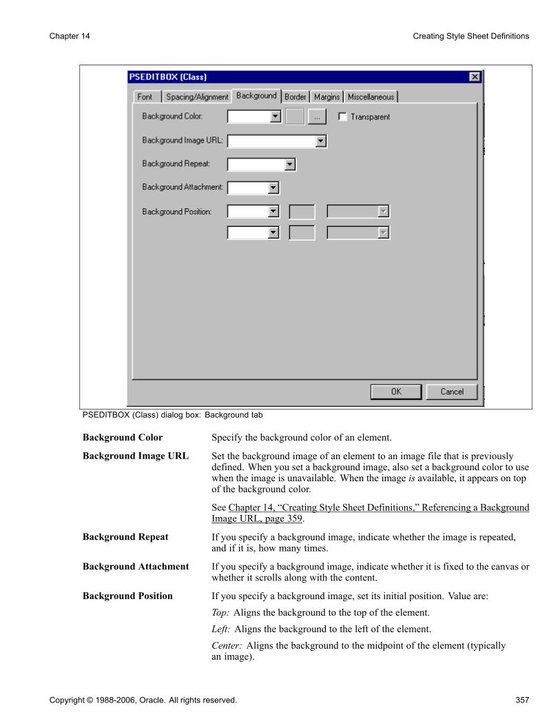
Chapter 14 Creating Style Sheet Definitions
PSEDITBOX (Class) dialog box: Background tab
Background Color Specify the background color of an element.
Background Image URL Set the background image of an element to an image file that is previouslydefined. When you set a background image, also set a background color to usewhen the image is unavailable. When the image is available, it appears on topof the background color.
See Chapter 14, “Creating Style Sheet Definitions,” Referencing a BackgroundImage URL, page 359.
Background Repeat If you specify a background image, indicate whether the image is repeated,and if it is, how many times.
Background Attachment If you specify a background image, indicate whether it is fixed to the canvas orwhether it scrolls along with the content.
Background Position If you specify a background image, set its initial position. Value are:Top: Aligns the background to the top of the element.Left: Aligns the background to the left of the element.Center: Aligns the background to the midpoint of the element (typicallyan image).
Copyright © 1988-2006, Oracle. All rights reserved. 357

Creating Style Sheet Definitions Chapter 14
Bottom: Aligns the background to the bottom of the element.Right: Aligns the background to the right of the element.Length: Specify the length of the background and the unit of measure.Percentage: Refers to the value of the line-height property of the backgrounditself. It raises the baseline of the element (or the bottom, if it has no baseline)the specified amount above the baseline of the parent. Negative values arepossible. For example, a value of −100% lowers the element so that thebaseline of the element is where the baseline of the next line should have been.This allows precise control over the vertical position of elements without abaseline, such as images used in place of letters.
Examples of Percentage and Length Value Pairs and KeywordsThis table lists background positions, value pairs, and their effect:
Background Position Value Pairs Effect
Percentage 0 and 0 Places the upper, left-hand cornerof the image in the upper, left-handcorner of the box that surrounds thecontent of the element (that is, notthe box that surrounds the padding,border, or margin).
Percentage 100 and 100 Places the lower, right-hand cornerof the image in the lower, right-handcorner of the element
Percentage 14 and 84 Places the point that is 14 percentacross and 84 percent down theimage at the point that is 14 percentacross and 84 percent down theelement.
Length 2cm and 2cm Places the upper, left-hand cornerof the image 2 centimeters (cm) tothe right and 2 cm below the upper,left-hand corner of the element.
Top Left or Left Top NA The same as 0 percent and 0 percent.
Top Center or Center Top NA The same as 50 percent and 0percent.
Right Top or Top Right NA The same as 100 percent and 0percent.
358 Copyright © 1988-2006, Oracle. All rights reserved.
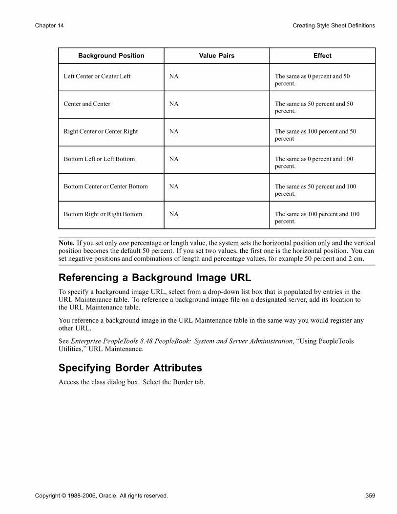
Chapter 14 Creating Style Sheet Definitions
Background Position Value Pairs Effect
Left Center or Center Left NA The same as 0 percent and 50percent.
Center and Center NA The same as 50 percent and 50percent.
Right Center or Center Right NA The same as 100 percent and 50percent
Bottom Left or Left Bottom NA The same as 0 percent and 100percent.
Bottom Center or Center Bottom NA The same as 50 percent and 100percent.
Bottom Right or Right Bottom NA The same as 100 percent and 100percent.
Note. If you set only one percentage or length value, the system sets the horizontal position only and the verticalposition becomes the default 50 percent. If you set two values, the first one is the horizontal position. You canset negative positions and combinations of length and percentage values, for example 50 percent and 2 cm.
Referencing a Background Image URLTo specify a background image URL, select from a drop-down list box that is populated by entries in theURL Maintenance table. To reference a background image file on a designated server, add its location tothe URL Maintenance table.
You reference a background image in the URL Maintenance table in the same way you would register anyother URL.
See Enterprise PeopleTools 8.48 PeopleBook: System and Server Administration, “Using PeopleToolsUtilities,” URL Maintenance.
Specifying Border AttributesAccess the class dialog box. Select the Border tab.
Copyright © 1988-2006, Oracle. All rights reserved. 359

Creating Style Sheet Definitions Chapter 14
PSGROUPBOX (Class) dialog box: Border tab
Border Width Specify the width of each line in the border. Values are:Thin, Medium, orThick, or you can specify Length, which enables you to specify a font size(with a number) and the measurement type from the drop-down list box(Pixels, Inches, Millimeters, and so on).
Border Color Specify the color of each line in the border. You can specify a hexadecimalvalue for the color or select the color from a color palette.
Border Style Specify the style of line in the border. Values are:None: No border is drawn (regardless of the <border-width> value).Dotted: Border is a dotted line that is drawn on top of the background ofthe element.Dashed: Border is a dashed line that is drawn on top of the background ofthe element.Solid: Border is a solid line.Double: Border is a double line that is drawn on top of the background ofthe element. The sum of the two single lines and the space between equalsthe <border-width> value.
360 Copyright © 1988-2006, Oracle. All rights reserved.

Chapter 14 Creating Style Sheet Definitions
Groove: Border is a three-dimensional groove that is drawn in colors based onthe <color> value.Ridge: Border is a three-dimensional ridge that is drawn in colors based onthe <color> value.Inset: Border is a three-dimensional inset that is drawn in colors based onthe <color> value.Outset: Border is a three-dimensional outset is that is drawn in colors based onthe <color> value.
Specifying MarginsAccess the class dialog box. Select the Margins tab.
PSGROUPBOX (Class) dialog box: Margins tab
Margin and Padding Specify the margin and padding for each side of the element. Values are:
Length: Specify a font size and the measurement type from the drop-downlist box (pixels, inches, millimeters, and so on).
Percentage: Specify a number, followed by a percent sign (%). The percentagevalue is relative to the parent element.
Copyright © 1988-2006, Oracle. All rights reserved. 361

Creating Style Sheet Definitions Chapter 14
Auto: The system calculates the width.Do not use negative values for padding.
Width and Height Set the width and height of text elements. These properties are most usefulwith replaced elements, such as images. The system scales the image to fitthe value that you specify. If you set either property to Auto, and the imageneeds scaling, the system preserves the aspect ratio of the image. Do notuse negative values.
Note. If the width and height of a replaced element are both set to Auto, thesystem sets these properties to the intrinsic dimensions of the element.
Specifying Miscellaneous AttributesAccess the class dialog box. Select the Miscellaneous tab.
PSHYPERLINK (Class) dialog box: Miscellaneous tab
List Style Type Specify the appearance of the list-item marker if List Style Image URL isblank or if the system cannot display the image that is referenced by the URL.
362 Copyright © 1988-2006, Oracle. All rights reserved.
Chapter 14 Creating Style Sheet Definitions
List Style Image Url (liststyle image uniform resourcelocator)
Specify the URL containing the image to display as the list-item marker.
List Style Position Specify how the list-item marker is drawn relative to the content. Valuesare: Inside and Outside.
Display Specify how an element is displayed on the canvas (which might be on aprinted page or a computer display). Values are:
Block: Opens a new box. The box is positioned relative to adjacent boxes.Typically, elements like H1 and P are block types.
ListItem: Similar to block, except that a ListItem marker is added. In HTML,LI typically has this value.
Inline: Results in a new inline box on the same line as the previous content.The box dimensions are based on the formatted size of the content. If thecontent is text, it might span several lines, and there will be a box on eachline. The margin, border, and padding properties apply to inline elementsbut do not affect the line breaks.
None: Deactivates the display of the element, including children elementsand the surrounding box.
Float Specify how the element floats with the text. Values are:None: Causes the element to appear where it appears in the text.Left and Right: Cause the element to move to the left or right, and the textwraps on the right-hand or left-hand side of the element, respectively. Witha Left or Right value, the element is treated as block-level and the Displayproperty is ignored.
Clear Specify the sides of an element on which floating elements are not accepted.Values are:
Left: An element appears below any floating element on the left-hand side.
None: Floating elements are allowed on all sides.
Transform Use for text elements only. Values are: Capitalize, Uppercase, Lowercase,and None.
Cursor Specify how the cursor displays when passed over the element.
Pseudo ClassesPseudo classes are mechanisms that extend the expressiveness of style sheets. Using pseudo classes, you canchange the style of page links based on whether and when the links have been visited. Pseudo classes do notexist in HTML; that is, they are not visible in the HTML code.
PeopleSoft uses pseudo classes to specify how a browser indicates to a user the status of links in a documentthat the user is viewing. For example, it is common for a browser to display a document link in a differentcolor than the rest of the text.
Link Specify how the link should appear normally.
Visited Specify how the link should appear if it has been visited.
Active Specify how the link should appear when it is actively selected.
Copyright © 1988-2006, Oracle. All rights reserved. 363

Creating Style Sheet Definitions Chapter 14
Hover Specify how the link should appear when it is designated but not activated. Forexample, when the cursor hovers over a box that is generated by the element.
Disabled Field Specify how the link should appear when the link (or field) is disabled.
Changing the Default Style Sheets for an ApplicationYou can change the default style sheet for an entire application on the PeopleTools Options page. PeopleSoftPure Internet Architecture generated pages always default to the style sheet you specify on this page. Thesystem default style sheet is PSSTYLEDEF.
To change the default style sheet for the application:
1. From your browser, select PeopleTools, Utilities, Administration, PeopleTools Options.
2. Type in the style sheet name in the Style Sheet Name field.
Alternatively, click the prompt button to select one from the list of available values.
3. Save the page.
Specifying a Style Sheet for a PageTo specify styles for a page:
1. Open the page in PeopleSoft Application Designer.2. Access the Page Properties dialog box.3. Select the Use tab.4. Select a style sheet from the Page Style Sheet drop-down list box.Selecting a different page style sheet for a specific page overrides the style sheet that is selected for theapplication. If you do not select a different page style sheet (keeping Use Default Style), the system usesthe style sheet that is specified on the PeopleTools Options page.
5. Select a page background from the drop-down list box.Selecting a different page background style class for a specific page overrides the background style of thepage style sheet that you just specified. If you keep the Use Default Style value, the background of thispage is determined by the default background of the page style sheet that you just specified.
Changing Colors on TabsThis section provides an overview of tab definitions and discusses how to create tab images.
364 Copyright © 1988-2006, Oracle. All rights reserved.
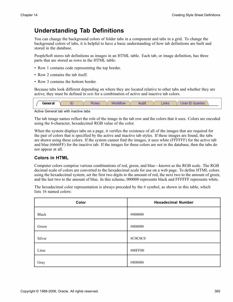
Chapter 14 Creating Style Sheet Definitions
Understanding Tab DefinitionsYou can change the background colors of folder tabs in a component and tabs in a grid. To change thebackground colors of tabs, it is helpful to have a basic understanding of how tab definitions are built andstored in the database.
PeopleSoft stores tab definitions as images in an HTML table. Each tab, or image definition, has threeparts that are stored as rows in the HTML table:
• Row 1 contains code representing the top border.• Row 2 contains the tab itself.• Row 3 contains the bottom border.
Because tabs look different depending on where they are located relative to other tabs and whether they areactive, they must be defined in sets for a combination of active and inactive tab colors.
Active General tab with inactive tabs
The tab image names reflect the role of the image in the tab row and the colors that it uses. Colors are encodedusing the 6-character, hexadecimal RGB value of the color.
When the system displays tabs on a page, it verifies the existence of all of the images that are required forthe pair of colors that is specified by the active and inactive tab styles. If these images are found, the tabsare drawn using these colors. If the system cannot find the images, it uses white (FFFFFF) for the active taband blue (6666FF) for the inactive tab. If the images for these colors are not in the database, then the tabs donot appear at all.
Colors in HTMLComputer colors comprise various combinations of red, green, and blue—known as the RGB scale. The RGBdecimal scale of colors are converted to the hexadecimal scale for use on a web page. To define HTML colorsusing the hexadecimal system, set the first two digits to the amount of red, the next two to the amount of green,and the last two to the amount of blue. In this scheme, 000000 represents black and FFFFFF represents white.
The hexadecimal color representation is always preceded by the # symbol, as shown in this table, whichlists 16 named colors:
Color Hexadecimal Number
Black #000000
Green #008000
Silver #C0C0C0
Lime #00FF00
Gray #808080
Copyright © 1988-2006, Oracle. All rights reserved. 365
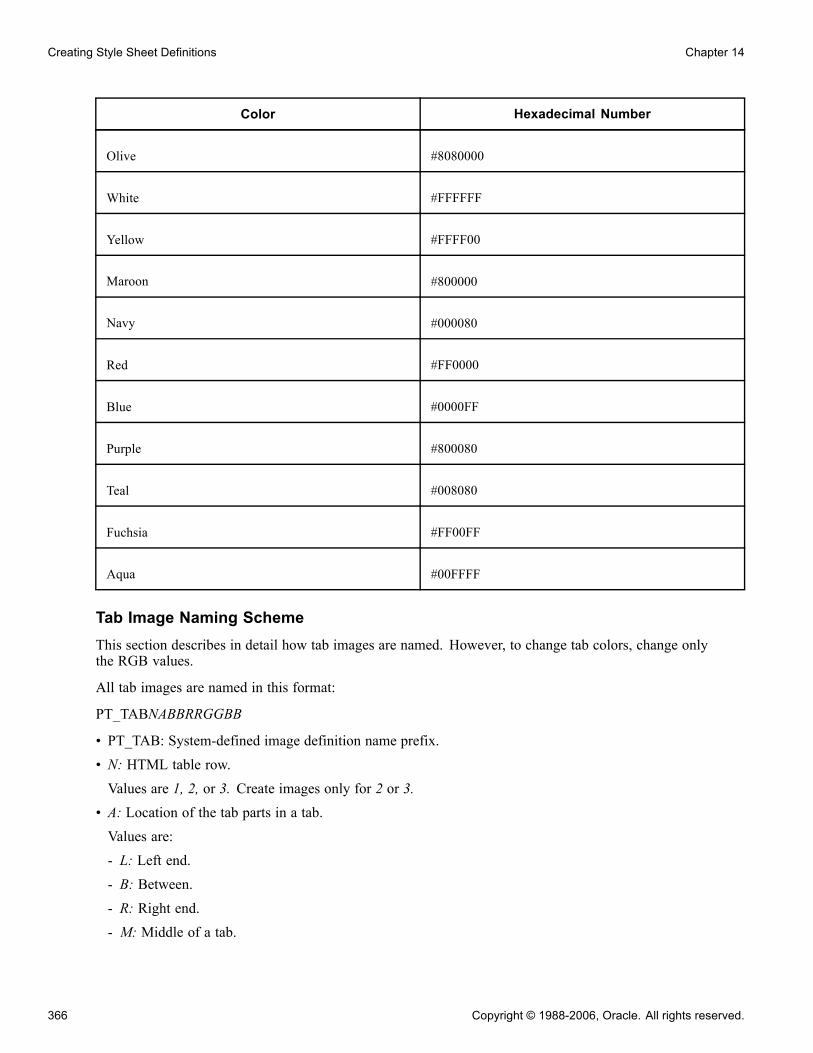
Creating Style Sheet Definitions Chapter 14
Color Hexadecimal Number
Olive #8080000
White #FFFFFF
Yellow #FFFF00
Maroon #800000
Navy #000080
Red #FF0000
Blue #0000FF
Purple #800080
Teal #008080
Fuchsia #FF00FF
Aqua #00FFFF
Tab Image Naming SchemeThis section describes in detail how tab images are named. However, to change tab colors, change onlythe RGB values.
All tab images are named in this format:
PT_TABNABBRRGGBB
• PT_TAB: System-defined image definition name prefix.• N: HTML table row.Values are 1, 2, or 3. Create images only for 2 or 3.
• A: Location of the tab parts in a tab.Values are:- L: Left end.- B: Between.- R: Right end.- M: Middle of a tab.
366 Copyright © 1988-2006, Oracle. All rights reserved.

Chapter 14 Creating Style Sheet Definitions
• BB: Relative position to other tabs.Values are:- AI: Piece between active and inactive.- IA: Piece between inactive and active.- II: Piece between two inactive tabs.- AX: Piece of an active tab.- IX: Piece of an inactive tab.
• RRGGBB is either omitted (when the tab image does not use any color), or it is one or two 6-characterhexadecimal codes for inactive and active tab colors.This screen shot shows a partial list of predefined tab images:
Predefined tab images
The first entry in the table is PT_TAB2BAIB8090FFFFFF, which represents a tab (PT_TAB2) part inthe second row of the HTML table, BAI (between an active and inactive tab), B8B090 (inactive tab colorof beige), and FFFFFF (active tab color of white). When the tab image requires two colors, the inactivetab color is always listed first.
Copyright © 1988-2006, Oracle. All rights reserved. 367

Creating Style Sheet Definitions Chapter 14
Creating Tab ImagesBefore you can assign a new background color to the active or inactive tabs, you must create the necessary tabimages with that color.
To produce tabs in a different color combination:
1. Open the image definitions for the tabs that you want to change.Because you want to change only the color of tabs, open only those image definitions that alreadycontain an RGB color code.If you are changing both the active and inactive tab color, access these image definitions:• PT_TAB2LAXFFFFFF• PT_TAB2RAXFFFFFF• PT_TAB2LIXB8B090• PT_TAB2RIXB8B090• PT_TAB2BAIB8B090FFFFFF• PT_TAB2BIAB8B090FFFFFF• PT_TAB2BIIB8B090• PT_TAB3LAXFFFFFF• PT_TAB3RAXFFFFFF• PT_TAB3MAXFFFFFF• PT_TAB3LIXB8B090• PT_TAB3RIXB8B090• PT_TAB3MIXB8B090• PT_TAB3BAIB8B090FFFFFF• PT_TAB3BIAB8B090FFFFFF• PT_TAB3BIIB8B090If you are changing only the inactive color, which is beige, you need only the files that contain thebeige color code, B8B090. Similarly, if you are changing only the active tab color, which is white,you need only the files that include FFFFFF. However, for the changes to apply, you must change allthose files with that color code. If one file is missed or there is a typographical error in the file name,the default style still applies.
2. To export the files to a directory, select File, Export Image.3. In the Save Image dialog box, select the directory in which you want to place the images.4. Use any image editor to alter the image colors.
Note. Do not change the size or shape of the images, and do not replace any of the transparent pixelswith solid pixels.
5. In PeopleSoft Application Designer, add the new image definitions by selecting File, New, Image.
368 Copyright © 1988-2006, Oracle. All rights reserved.
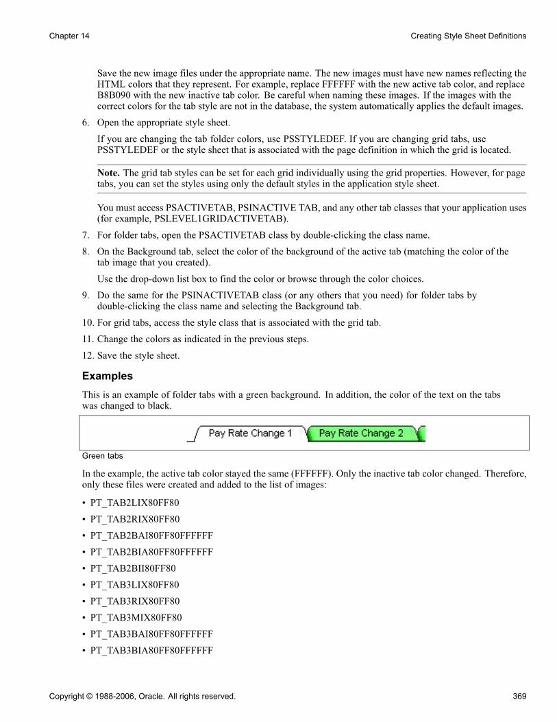
Chapter 14 Creating Style Sheet Definitions
Save the new image files under the appropriate name. The new images must have new names reflecting theHTML colors that they represent. For example, replace FFFFFF with the new active tab color, and replaceB8B090 with the new inactive tab color. Be careful when naming these images. If the images with thecorrect colors for the tab style are not in the database, the system automatically applies the default images.
6. Open the appropriate style sheet.If you are changing the tab folder colors, use PSSTYLEDEF. If you are changing grid tabs, usePSSTYLEDEF or the style sheet that is associated with the page definition in which the grid is located.
Note. The grid tab styles can be set for each grid individually using the grid properties. However, for pagetabs, you can set the styles using only the default styles in the application style sheet.
You must access PSACTIVETAB, PSINACTIVE TAB, and any other tab classes that your application uses(for example, PSLEVEL1GRIDACTIVETAB).
7. For folder tabs, open the PSACTIVETAB class by double-clicking the class name.8. On the Background tab, select the color of the background of the active tab (matching the color of thetab image that you created).Use the drop-down list box to find the color or browse through the color choices.
9. Do the same for the PSINACTIVETAB class (or any others that you need) for folder tabs bydouble-clicking the class name and selecting the Background tab.
10. For grid tabs, access the style class that is associated with the grid tab.11. Change the colors as indicated in the previous steps.12. Save the style sheet.
ExamplesThis is an example of folder tabs with a green background. In addition, the color of the text on the tabswas changed to black.
Green tabs
In the example, the active tab color stayed the same (FFFFFF). Only the inactive tab color changed. Therefore,only these files were created and added to the list of images:
• PT_TAB2LIX80FF80• PT_TAB2RIX80FF80• PT_TAB2BAI80FF80FFFFFF• PT_TAB2BIA80FF80FFFFFF• PT_TAB2BII80FF80• PT_TAB3LIX80FF80• PT_TAB3RIX80FF80• PT_TAB3MIX80FF80• PT_TAB3BAI80FF80FFFFFF• PT_TAB3BIA80FF80FFFFFF
Copyright © 1988-2006, Oracle. All rights reserved. 369

Creating Style Sheet Definitions Chapter 14
• PT_TAB3BII80FF80
370 Copyright © 1988-2006, Oracle. All rights reserved.

CHAPTER 15
Creating Image Definitions
This chapter provides an overview of images and discusses how to:
• Create new image definitions.• Open an image definition.• Update an image definition.• Convert images.• Consolidate images.• Use the catalog of image definitions.
Understanding ImagesImages improve the look and usability for the user. PeopleSoft Internet Architecture comes equipped withseveral different types of image-related features, each of which serves a different function. The followingtable provides a brief description of each image type:
Image Type Description
Image field Use for storing images in a user-defined format, such asbitmap (BMP) or PostScript (EPS). Image fields cannotbe changed at runtime.
ImageReference field Use to change an image dynamically at runtime by usingPeopleCode.
Image definition Use as the source from which all static images and imagefields are taken and used elsewhere in the system.
Image control Place on a page when you want a variable image that istaken from a record field in the database.
Static image control Use to place a static image definition on the page, suchas on a push button.
Copyright © 1988-2006, Oracle. All rights reserved. 371

Creating Image Definitions Chapter 15
Creating New Image DefinitionsThis section provides an overview of image definitions and discusses how to:
• Create an image definition.
• Set image properties.
• Import and create alternate image types.
Understanding Image DefinitionsImage definitions are managed PeopleSoft definitions that you can associate with a variety of page controls.They are primarily for aesthetic purposes, but can also demonstrate a simple function, such as an arrow on apush button. Many organizations store images along with the rest of their employee, customer, and supplierdata as part of their ongoing business operations. For example:
• Retailers often store images of each product with the standard merchandise information that they useto manage inventory.Online retailers can display product pictures on their customer web sites.
• Many organizations store images of each employee as part of their standard human resources information.• Consumer banks might store images of their customers’ canceled checks.
PeopleSoft Application Designer enables you to create an image definition from any type of image fileand store it in a central PeopleTools image catalog. In this process, you convert the image files into imagedefinitions and store them in the image catalog so that you can refer to them from a PeopleTools application.After you create the image definition, it is available for use throughout the system, such as in a static imagepage control or on a push button or link.
Image TypesWhen creating new image definitions to use with applications, you might want to use different image typesfor different purposes. Some developers believe, for example, that JPG is the best format for photographicimages because it provides the greatest compression of any bitmap format in common use. However, somebelieve that JPG is not as effective in compressing text and drawings as it is at compressing photographs. GIFimages, on the other hand, seem to be the most widely used format for image storage and continue to be thepreferred format for storing text and drawings. Regardless of your image type preferences, PeopleSoft enablesyou to store all image types in the image catalog.
However, two image types (GIF and WBMP) cannot be viewed in PeopleSoft Application Designer duringdesign time, but they can be viewed through the browser at runtime. By providing an alternate image type ofthe image, such as JPG, PeopleSoft enables you to import images for viewing purposes only in PeopleSoftApplication Designer. The image that you view at runtime in the browser or in the wireless application isstill the original GIF or WBMP image.
Creating an Image DefinitionTo create an image definition from an image file:
1. Select File, New.
2. Select Image.
3. Click OK to access the Open Image File dialog box.
372 Copyright © 1988-2006, Oracle. All rights reserved.
Chapter 15 Creating Image Definitions
4. Select an image file type.You can select from several file types, such as BMP, wireless bitmap (WBMP), device independent bitmap(DIB), Graphics Interchange Format (GIF), and Joint Photographic Experts Group (JPEG). You can createan image definition by using any file type. GIF and WBMP images are considered alternate image types.
See Chapter 15, “Creating Image Definitions,” Importing and Creating Alternate Image Types, page 374.
Note. Some browsers do not support all image types. For example, Netscape does not support BMP images.
See Customer Connection, "Troubleshooting Browser Limitations."5. Select an image file name.PeopleSoft Application Designer displays a warning message if the image size is greater than 32 kilobytes.The maximum image size depends on the database platform that you are using. Some database platformssupport much larger image sizes while others limit the size.
6. Select Open.The image is now open as an image definition in the definition workspace.
7. Select File, Save to save the image definition in the PeopleSoft image repository.Upon saving, the Image Properties dialog box appears.
Setting Image PropertiesAfter you create a new image definition, you can set the image properties.
To set image properties:
1. Access the Image Properties dialog box.If not already open, select File, Definition Properties.
2. (Optional) Enter a description on the General tab.3. Select the Use tab to view image use properties.
Image Format Specify the main and alternate image formats. The main image format,which appears at runtime, is the format in which the image was imported,such as BMP. The alternate format is the optional image format thatyou can specify if you want a GIF image as the main image format thatappears at runtime.
Image URL(image uniformresource locator)
Specify a reference to an image on a web server. This can be used as analternative to storing an image definition in the database once an imagedefinition is saved. When the user opens a page containing a control thatis associated with this image definition, the application retrieves theimage from the URL, rather than from the database. Set up URLs in theURL Maintenance utility.
See Enterprise PeopleTools 8.48 PeopleBook: System and ServerAdministration, “Using PeopleTools Utilities,” URL Maintenance.
Used in Workflow Maps Select to filter images that appear in a list box for the Change Icon functionfor PeopleSoft Workflow designers.
Copyright © 1988-2006, Oracle. All rights reserved. 373

Creating Image Definitions Chapter 15
Importing and Creating Alternate Image TypesTo import a GIF or WBMP image type:
1. Select File, New.2. Select Image.The Open Image File dialog box appears.
3. Select GIF or WBMP from the Files of Type drop-down list box.4. Locate the image that you want to import.5. Click the Open button.The Content Repository Interface dialog box appears, prompting you to select an alternate image.
6. Select Yes.The Open Alternate Image File dialog box appears, prompting you to select an alternate image type.You must have the same image stored in the directory under a different file type, such as JPG, to viewthe image in PeopleSoft Application Designer. If you select No, you can still open the GIF or WBMPimage definition, but you cannot see it. Instead, you receive a message that the image cannot be viewedin PeopleSoft Application Designer.
7. Select the alternate image format and the appropriate file.8. Click Open.You cannot select a GIF image as an alternate image type for WBMP images, nor can you select a WBMPimage as an alternate image type for a GIF image.
9. Select File, Save As.Upon saving, the Image Properties dialog box appears. If you select the Use tab, the Image Format groupbox shows the main image format as GIF (or WBMP) and the alternate as JPG. Now you can view theimage in PeopleSoft Application Designer as a JPG image and still display the image at runtime asGIF (or WBMP).
Opening an Image DefinitionTo open an image definition:
1. Select File, Open.2. Select Image from the Definition drop-down list box.3. Click Open to view the full list of image definitions and brief descriptions.
Updating an Image DefinitionThis section discusses how to:
• Update an image definition.
• Change the image display size.
374 Copyright © 1988-2006, Oracle. All rights reserved.
Chapter 15 Creating Image Definitions
• Specify the image storage format.
Updating an Image DefinitionOccasionally, the original image file from which you created an image definition might change. To keep theimage definitions current, you might want to update them rather than create entirely new image definitions.
To update an image definition:
1. To change the image for a saved image definition, right-click the open definition and select Update Image.The Open Image File dialog box appears, in which you can select the changed image file to replace theopen image definition.
2. Click Open.This replaces the previous image in the image definition with the new image that you selected.
3. Select File, Save to save the current image definition with the new image.
Changing the Image Display SizeIf the image file is smaller than you want it to appear in the open image definition, you can increase the size byzooming in on the definition workspace. This does not alter the size of the image in the image catalog.
To change image definition display size:
1. Open the image.
2. Right-click the image and select Zoom to see the different size ratios.
3. Select a new image display percentage.
The image automatically changes to that selection.
Specifying the Image Storage FormatYou can specify a default format in which image definitions are stored. For example, if JPG is specified as thepreferred storage format, then a BMP image is stored as a JPG after it is converted to an image definition.
To specify an image definition storage format:
1. Select Tools, Options to open the Options dialog box.2. Select the Image tab.
No conversion Select to import all image definitions in their original formats. This isthe default.
DIB and JPG Select to convert and store imported image definitions as either DIB orJPG in the PeopleSoft Application Designer image catalog. GIF andWBMP images cannot be converted to DIB or JPG.
3. Click OK.
Copyright © 1988-2006, Oracle. All rights reserved. 375

Creating Image Definitions Chapter 15
Converting ImagesNot all browsers support all image formats, but most browsers support the JPG image type. Therefore,PeopleSoft has a utility to convert all application images to JPG.
Convert Images dialog box
To convert images to JPG format:
1. Select Tools, Upgrade, Convert Images.
2. Select one of these check boxes:
Convert Static Images inImage Catalog
Converts all image definitions that are stored in the image catalog ofthe PeopleSoft database.
Convert Dynamic Imagesfor fields
Converts all images that are dynamically referenced by PeopleCode toappear in image fields.
3. Select the fields to convert.4. Click the Start button.When the process is complete, a confirmation message appears in the Image tab of the output window.
Consolidating ImagesUse this tool if you create custom image definitions and use them in multiple record definitions. Consolidatingimages helps you avoid having the same image stored in several places. All image definitions that arepackaged with the PeopleSoft system have already been consolidated.
376 Copyright © 1988-2006, Oracle. All rights reserved.
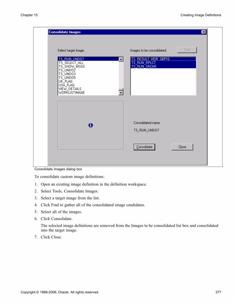
Chapter 15 Creating Image Definitions
Consolidate Images dialog box
To consolidate custom image definitions:
1. Open an existing image definition in the definition workspace.2. Select Tools, Consolidate Images.3. Select a target image from the list.4. Click Find to gather all of the consolidated image candidates.5. Select all of the images.6. Click Consolidate.The selected image definitions are removed from the Images to be consolidated list box and consolidatedinto the target image.
7. Click Close.
Copyright © 1988-2006, Oracle. All rights reserved. 377

Creating Image Definitions Chapter 15
Using the Catalog of Image DefinitionsIn addition to the image definitions that you create, the system comes with many predefined image definitions.You can use these images to identify an action that a user must perform on a page or for aesthetic purposesonly. For example, you can access an image either by inserting it onto a page as a static image or by specifyingit as a label on a push button to accompany a specific function.
The following tables list some of the common image definitions in the image catalog that are used byPeopleTools in the deployment of internet applications. PeopleSoft does not recommend changing any of theseimages. You can also use Structured Query Language (SQL) to view a full list of different images:
SELECT DISTINCT CONTNAME FROM PSCONTDEFN WHERE CONTTYPE = 1.
For a list of language-dependent versions of images, use the following SQL:SELECT CONTNAME, LANGUAGE_CD, CONTTYPE CONTFMT DESCR FROM
PSCONTDEFNLANG WHERE CONTTYPE = 1
Note. Before logging into PeopleSoft Application Designer in a different language, the language support mustfirst be enabled. Use PeopleTools Utilities to enable support.
In general:
• All PeopleTools image definitions start with PT_.• Any image definition with _D at the end of the name is the disabled mode of the image.• All images that start with PT_TAB are used for tab construction and colors.
It is important to use these images consistently as you create new pages and update pages in the applications.The images are categorized by function and listed alphabetically by image name.
Note. This list contains a sample of the common images in PeopleSoft Application Designer, but it is not acomplete list of PeopleTools images. For a complete list of images, select File, Open, Image. Click Opento see the full list of images.
ToolbarIn previous releases, the entire toolbar button (Save, Next in List, and so on) was an image, including thetext in the button. Currently, the button is an HTML button and the text is specified in HTML, only the iconis an image. This enables you to change the color of the button using a style class. Toolbar buttons arerendered as HTML buttons, not images.
Scroll or Grid ActionsUse these images when creating scroll areas, scroll bars, and grids.
PT_ADD: Add a row.
PT_ADD_LARGE: Large add a row button. Alternative to PT_ADD ifthere is enough room on the page.
PT_DELETE: Delete a row.
378 Copyright © 1988-2006, Oracle. All rights reserved.

Chapter 15 Creating Image Definitions
PT_DELETE_LARGE: Large delete a row button. Alternative toPT_DELETE if there is enough room on the page.
PT_GRID_NO_TABS: Expand grid columns horizontally so that grid tabs areno longer showing.
PT_GRID_SHOW_TABS: Return an expanded grid to a tabbed grid.
PT_NEXTROW: View the next row.
PT_PREVIOUSROW: View the previous row.
Tab ImagesUse these images to change the look of both folder and grid tabs.
PT_TAB_LSCROLL: Scroll left to the previous tab in a page or grid.
PT_TAB_RSCROLL: Scroll right to the next tab in a page or grid.
PT_TABxxx through PT_TABxxxxxxxx: Selection of over 80 images thatcan be used for creating folder tabs.
Look-up and Search Page ImagesUse these images on look-up and search pages.
PT_CANCEL: Cancel a look-up page.
PT_CLEAR: Clear search criteria from the page (appears only on theAdvanced Search/Lookup page).
PT_LOOKUP: Begin looking up data.
PT_SEARCH: Start a search on the search page.
General
PT_ABORT: Abort a transaction. Used in some PeopleCode message boxes.
PT_APPLY: Applies changes that were made to the database. Usually foundwhen transferring to another page through PeopleCode.
PT_CALENDAR: Opens the calendar prompt.
Copyright © 1988-2006, Oracle. All rights reserved. 379

Creating Image Definitions Chapter 15
PT_COPYURL: Used in the pagebar. Copies contents of address bar tothe clipboard.
PT_IGNORE: Used in some PeopleCode message boxes.
PT_NO: Used in some PeopleCode message boxes.
PT_OK: Accept the input on a secondary page and return to the main page.
PT_POPUP: Opens a pop-up menu from which the user can select a pageto transfer to.
PT_POPUP_SKIP: Use if a pop-up menu has only one menu item to selectfrom, so the user is brought directly to the page.
PT_PRINT: Open the print dialog box for the designated item.
PT_PROCESSING: Appears as flashing text while accessing a server ordatabase.
PT_PROMPT_LOOKUP: Look-up button for a field prompt table.
PT_SPELLCHECK: Opens the spell check page for the current field.
PT_REPORT_DIST_ICN: Usually found on the Process Scheduler Requestpage, this button takes you to the Distribution Detail page. Use to select rolesand users who can access or receive an email of report output.
PT_SEC_RETURN: Return from a secondary page to the main (calling) page.
PT_WF_ACTIVITY: Used for a subprocess of the business task for workflow,consisting of one or more steps.
PT_WF_BUSPROC: Depict a complete business task for workflow.
PT_WF_STEP: Show a discrete step in the business process, corresponding toa single transaction that is performed on an application page or through anexternal program.
Query Images
PT_QUERY_ADD_CRITERIA: Add criteria to a query.
PT_QUERY_KEY: Denotes a query key field.
PT_QUERY_SORT: Sort query fields alphabetically.
380 Copyright © 1988-2006, Oracle. All rights reserved.

Chapter 15 Creating Image Definitions
Tree ImagesUse these tree images with PeopleSoft Tree Manager.
Tree node and leaf images include:
PSTREEMGR_COL_BRANCH: Identifies the root node for a branch.
PSTREEMGR_COL_NODE: Standard node image.
PSTREEMGR_COL_SKNODE: Tree node that has skipped a level.
PSTREEMGR_END_NODE: Tree node that has no children; that is, aterminal node.
PSTREEMGR_EXP_BRANCH: Root node on a branched tree.
PSTREEMGR_EXP_NODE: Expanded node.
PSTREEMGR_EXP_SKNODE: Expanded node that has skipped a level.
PSTREEMGR_LEAF: Lowest-level detail value of a tree.
Node and leaf command button images include:
PTTREE_ADDCHILD: Add a new child node.
PTTREE_ADDLEAF: Add a new detail value, such as a leaf.
PTTREE_ADDSIB: Add a new node as a sibling to the selected node.
PTTREE_CUT: Cut a node or leaf and place it on the clipboard.
PTTREE_DELETELEAF: Delete a leaf.
PTTREE_DELETENODE: Delete a node.
PTTREE_DISP_AS_ROOT: Redisplay the tree, starting with the currentlyselected node being displayed as the root node.
PTTREE_EDITDATA: Display the underlying user data page.
PTTREE_MAKEBRANCH: Create a new tree branch, starting with theselected node.
PTTREE_PASTECHILD: Paste the node on the clipboard as a child of thecurrently selected node.
Copyright © 1988-2006, Oracle. All rights reserved. 381

Creating Image Definitions Chapter 15
PTTREE_PASTESIB: Paste the node on the clipboard as a sibling of thecurrently selected node.
PTTREE_UNBRANCH: Unbranch a branch.
PTTREE_UPDATELEAF: Update the values and properties for a leaf.
PTTREE_UPDATENODE: Update the value or properties for a node.
Portal ImagesUse these images to perform a specific action. Additional portal images, such as PT_PORTAL_HEADER_BG,are purely aesthetic. In general, all images that are reserved for the portal contain the word PORTAL in theimage name, such as PT_PORTAL_SEPARATOR.
PT_PORTAL_DOWN_ARROW_Y: Move a pagelet down when personalizingthe portal layout.
PT_PORTAL_IC_CLOSE: Remove a pagelet from the homepage.
382 Copyright © 1988-2006, Oracle. All rights reserved.

CHAPTER 16
Creating HTML Definitions
This chapter provides an overview of HTML definitions and discusses how to:
• Create an HTML definition.• Open an HTML definition.• Reference HTML definitions dynamically.
Understanding HTML DefinitionsAn HTML definition is a blank window where you can enter HTML. Use HTML definitions for storing longstrings of HTML text or HTML text that you use repeatedly in your application. You can later access thedefinition dynamically from an HTML area control by using the GetHTMLText PeopleCode function.
See Enterprise PeopleTools 8.48 PeopleBook: PeopleCode Language Reference, “PeopleCode Built-inFunctions,” GetHTMLText.
You can reference HTML definitions from an HTML area control statically or dynamically. However, themost common usage is to reference HTML definitions dynamically.
Creating an HTML DefinitionTo create an HTML definition:
1. Select File, New.The New Definition dialog box opens enabling you to select the definition you want.
2. Select HTML from the scroll area.3. Click OK to open a new HTML definition.4. Type or paste the HTML text directly into the open definition window.5. Select File, Save to save the HTML definition.The HTML definition is saved in the current database.
Copyright © 1988-2006, Oracle. All rights reserved. 383
Creating HTML Definitions Chapter 16
Opening an HTML DefinitionTo open an HTML Definition:
1. Select File, Open to access the Open Definition dialog box.
2. Select HTML from the Definition drop-down list box.
3. Click Open to show all of the HTML definitions that are currently stored in the database.
You can also enter a letter or word in the Name edit box to filter the display. For example, entering theletter H reveals all of the HTML definitions that begin with H in the database.
Naming a group of HTML definitions with the same introductory phrase can help keep them together foreasy selecting.
Referencing HTML Definitions DynamicallyTo reference an HTML definition dynamically:
1. Add an HTML area control to a page definition.2. Open the HTML Area Properties dialog box.3. On the HTML tab, enter the GetHTMLText PeopleCode function for the HTML definition that youwant to reference.
4. Click OK.
See AlsoChapter 9, “Using Page Controls,” Populating an HTML Area, page 229
Chapter 10, “Creating Page Definitions,” Adding Page Controls, page 265
Enterprise PeopleTools 8.48 PeopleBook: PeopleCode Developer’s Guide, “PeopleCode and PeopleSoft PureInternet Architecture,” Using HTML Definitions and the GetHTMLText Function
384 Copyright © 1988-2006, Oracle. All rights reserved.

PART 3
Maintaining Data
Chapter 17Constructing File Layouts and Performing Data Interchanges
Chapter 18Using Command Line Parameters
Chapter 19Using Change Control

CHAPTER 17
Constructing File Layouts and PerformingData Interchanges
This chapter provides an overview of file layouts and discusses how to:
• Construct file layouts.• Specify file layout, record, and field properties.• Perform data interchanges.• Produce a sample file layout.
Understanding File LayoutsThis section discusses:
• File layouts.• Field formats in a flat file.• Fixed-position (FIXED) format files.• Comma-separated value (CSV) format files.• XML-tagged (XML) format files.
Understanding File LayoutsA file layout is a definition that represents the data structure of a flat (text) file to be processed. When readingfrom or writing to a flat file, the PeopleCode can use a file layout as a template to identify and correctly processthe file’s records and fields. File layouts work with hierarchical and nonhierarchical data, and they can handlefiles that combine data records with nondata (audit or control) records.
To access data in a file, you don’t have to create a file layout. PeopleTools supports reading and writing toplain text files, as well as to files that have a format based on a file layout.
• If the file is a plain text file, data is read or written by using text strings.• If the file is based on a file layout, you can use text strings, rowsets, or record objects.
Using a file layout greatly simplifies reading, writing, and manipulating hierarchical transaction data withPeopleCode. It can facilitate transactions between a PeopleSoft application and a third-party system when thethird-party system doesn’t support PeopleSoft Integration Broker or component interfaces.
Note. Do not create or save files in Excel and then use those files for file processing.
Copyright © 1988-2006, Oracle. All rights reserved. 387

Constructing File Layouts and Performing Data Interchanges Chapter 17
Applying File Layouts to Data InterchangesIn addition to manipulating transaction data, you can employ file layouts to move data between a PeopleSoftdatabase and external systems (data interchange) by using flat files as the transmission medium. File layoutsenable you to:
• Export hierarchical PeopleSoft data to several flat file formats.• Map incoming hierarchical file data directly to PeopleSoft tables.• Preview and troubleshoot the input data and its formatting before importing it.• Automatically generate the Application Engine and PeopleCode programs that are needed to performdata import.
• Use batch processes to perform large-volume data imports and exports.
See AlsoChapter 17, “Constructing File Layouts and Performing Data Interchanges,” Performing Data Interchanges,page 403
Enterprise PeopleTools 8.48 PeopleBook: PeopleCode API Reference, “File Class”
Field Formats in a Flat FileA flat file, in the simplest sense, is a collection of fields in text format. The file must be formatted in a way thatenables the PeopleCode to locate each field. PeopleSoft file layouts support three formats:
• FIXED: Each field has a starting position and a length that together specify its location in the file.This is the default format for new file layouts.
• CSV: Fields are located in the file by their sequence, separated by commas.• XML: A field is located not by its position or sequence within a record, but by the named XML tagssurrounding it.
To preserve relationships between fields, you group fields into logical collections. In relational databases,these collections are records. Each line within a file is a collection of fields.
Note. With some file formats, the logical concept of a record may actually span multiple physical lines, but theconcept of collections of fields remains.
The conceptual structure of all three file formats is represented in a file layout as follows:
File layout structure
A file layout is a collection of file records, which in turn are a collection of fields, each of which has adescribable location.
Note. To avoid confusion with the standard terms record and field, when working with a file layout we refer toa collection of fields as a file record and to fields as file fields.
388 Copyright © 1988-2006, Oracle. All rights reserved.
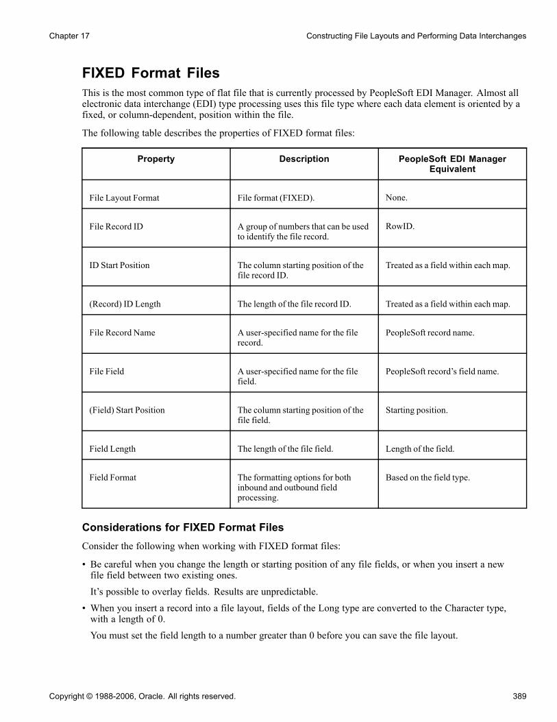
Chapter 17 Constructing File Layouts and Performing Data Interchanges
FIXED Format FilesThis is the most common type of flat file that is currently processed by PeopleSoft EDI Manager. Almost allelectronic data interchange (EDI) type processing uses this file type where each data element is oriented by afixed, or column-dependent, position within the file.
The following table describes the properties of FIXED format files:
Property Description PeopleSoft EDI ManagerEquivalent
File Layout Format File format (FIXED). None.
File Record ID A group of numbers that can be usedto identify the file record.
RowID.
ID Start Position The column starting position of thefile record ID.
Treated as a field within each map.
(Record) ID Length The length of the file record ID. Treated as a field within each map.
File Record Name A user-specified name for the filerecord.
PeopleSoft record name.
File Field A user-specified name for the filefield.
PeopleSoft record’s field name.
(Field) Start Position The column starting position of thefile field.
Starting position.
Field Length The length of the file field. Length of the field.
Field Format The formatting options for bothinbound and outbound fieldprocessing.
Based on the field type.
Considerations for FIXED Format FilesConsider the following when working with FIXED format files:
• Be careful when you change the length or starting position of any file fields, or when you insert a newfile field between two existing ones.It’s possible to overlay fields. Results are unpredictable.
• When you insert a record into a file layout, fields of the Long type are converted to the Character type,with a length of 0.You must set the field length to a number greater than 0 before you can save the file layout.
Copyright © 1988-2006, Oracle. All rights reserved. 389

Constructing File Layouts and Performing Data Interchanges Chapter 17
CSV Format FilesIn this type of file, each data element is surrounded with a separator, a delimiter, or both. File record IDs canbe used to determine which table data is moved to or from; however, in most cases this type of file containshomogenous records.
In the following example, the qualifier is a double quote (") and the delimiter is a comma (,):
"NAME","ADDRESS","PHONE"
File layout definitions store the file record ID (when used) and the relative sequence number of the field. In thepreceding example, "PHONE" is sequence number 3.
The following table describes the properties of CSV format files:
Property Description EDI Manager Equivalent
File Format File format (CSV). None.
File Record ID A group of numbers that can be usedto identify the file record.
RowID.
ID Sequence Number The sequence number of the fieldthat contains the file record ID.
Treated as a field within each map.
Qualifier The character that surrounds a fieldto mark its extent. This can be setat the file layout, file record, or filefield level.
Delimiter.
Delimiter The character used to separate fieldsfrom each other. This can be set atthe file layout or file record level.
Separator.
File Record Name A user-specified name for the filerecord.
None.
File Record Field A user-specified name for the filefield.
None.
Field Format The formatting options for bothinbound and outbound fieldprocessing.
Based on the field type.
Considerations for CSV Format FilesConsider the following when working with CSV format files:
• Both the qualifier and the delimiter accept a blank as a valid value.• If a field is null, you don’t have to use qualifiers.
390 Copyright © 1988-2006, Oracle. All rights reserved.

Chapter 17 Constructing File Layouts and Performing Data Interchanges
In the following example, Field2 is null:
Field1,,Field3,Field4. . .
• The system automatically pads the decimal places with zeros when amounts do not have values beyondthe decimal point.
For example, 100 is automatically written as 100.00.
Parsing Support for CSV Format FilesThe following list summarizes parsing support in preview and runtime for all CSV file types:
• All blank lines are ignored.
In the past, blank lines came in as empty records.
• All empty fields are returned as empty strings or zeros.
• Fields, including commas or new lines, are surrounded in quotes.
• When a field is in quotes, any embedded quotes must be escaped by two quotes.
• When non-Microsoft Excel format backslashes are embedded within a string, they must bedouble-backslashes to be interpreted as a backslash; otherwise, they are interpreted as an escape character.
Parsing Support for Microsoft Excel CSV FormatThe following table summarizes the differences between Microsoft Excel CSV parsing and non-MicrosoftExcel CSV parsing:
Item Microsoft Excel CSV ParsingNon-Microsoft Excel CSV
Parsing
White space Leading and trailing white space issignificant for strings.
Leading and trailing whites paces areignored, including converted tabs.
Backslashes Not interpreted as special characters,except for new lines.
Interpreted.
Quotes inside quoted strings Double-quoted. Escaped.
Tabs Converted to a single space. Interpreted as tabs and ignored.
XML Format FilesThis type of file contains data that is represented in a hierarchical or tree-type structure. A tag surrounds eachdata element. A file record tag might group multiple entries.
File layout definitions tie the identifier along with parent and child relationships to the file record and file field.
There is no PeopleSoft EDI Manager equivalent for this format.
The following table describes the properties of XML format files:
Copyright © 1988-2006, Oracle. All rights reserved. 391
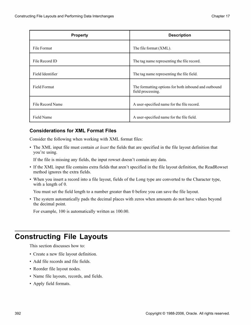
Constructing File Layouts and Performing Data Interchanges Chapter 17
Property Description
File Format The file format (XML).
File Record ID The tag name representing the file record.
Field Identifier The tag name representing the file field.
Field Format The formatting options for both inbound and outboundfield processing.
File Record Name A user-specified name for the file record.
Field Name A user-specified name for the file field.
Considerations for XML Format FilesConsider the following when working with XML format files:
• The XML input file must contain at least the fields that are specified in the file layout definition thatyou’re using.If the file is missing any fields, the input rowset doesn’t contain any data.
• If the XML input file contains extra fields that aren’t specified in the file layout definition, the ReadRowsetmethod ignores the extra fields.
• When you insert a record into a file layout, fields of the Long type are converted to the Character type,with a length of 0.You must set the field length to a number greater than 0 before you can save the file layout.
• The system automatically pads the decimal places with zeros when amounts do not have values beyondthe decimal point.For example, 100 is automatically written as 100.00.
Constructing File LayoutsThis section discusses how to:
• Create a new file layout definition.
• Add file records and file fields.
• Reorder file layout nodes.
• Name file layouts, records, and fields.
• Apply field formats.
392 Copyright © 1988-2006, Oracle. All rights reserved.
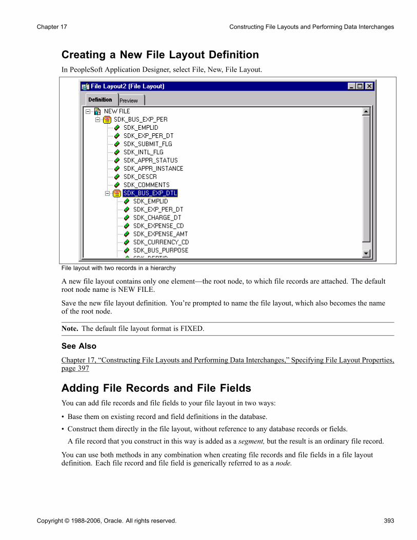
Chapter 17 Constructing File Layouts and Performing Data Interchanges
Creating a New File Layout DefinitionIn PeopleSoft Application Designer, select File, New, File Layout.
File layout with two records in a hierarchy
A new file layout contains only one element—the root node, to which file records are attached. The defaultroot node name is NEW FILE.
Save the new file layout definition. You’re prompted to name the file layout, which also becomes the nameof the root node.
Note. The default file layout format is FIXED.
See AlsoChapter 17, “Constructing File Layouts and Performing Data Interchanges,” Specifying File Layout Properties,page 397
Adding File Records and File FieldsYou can add file records and file fields to your file layout in two ways:
• Base them on existing record and field definitions in the database.• Construct them directly in the file layout, without reference to any database records or fields.A file record that you construct in this way is added as a segment, but the result is an ordinary file record.
You can use both methods in any combination when creating file records and file fields in a file layoutdefinition. Each file record and file field is generically referred to as a node.
Copyright © 1988-2006, Oracle. All rights reserved. 393

Constructing File Layouts and Performing Data Interchanges Chapter 17
Important! Regardless of the method that you use, file records and file fields exist only as definitions within afile layout and have no connection with any database record or field. Even with file records based on recordsin the database, a change to the database record definition is not reflected in the file layout.
Using a Segment Instead of a RecordSuppose that in the file that is provided to you, some of the file records contain new data and must beinserted, while others contain data that updates existing data. You can add a segment with a single field (likeAUDIT_ACTION) that indicates whether the file record is new or changed. When you process the file, youcan use PeopleCode to look at this field and, based on its value, perform the appropriate action.
As another example, suppose that you want to include two fields from the PERSONAL_DATA table in thefile, but not all of the other fields. You have two choices: insert the PERSONAL_DATA table and manuallydelete all of the unwanted fields, or insert a segment, name it PERSONAL_DATA, and then insert the twofields that you want.
Using Segments in Data InterchangesIf you’re creating a file layout for a data interchange, you can use segments, but each file record mustcorrespond to a record with the same name in the PeopleSoft database, and its file fields must have the samenames and data formats as the database record’s fields. The file record may contain a subset of the fields inthe corresponding database record. It may also contain a subset or a superset of the fields that are providedin the corresponding file data.
Adding File RecordsTo add a file record to the file layout definition, use one of the following methods:
• Drag and drop a database record.Drag a record definition from the Project window into the file layout’s Definition window, dropping it onthe root node or on any existing file record or file field. The new file record appears at the same level asthe node that you dropped it on, following all of the other file records at that level. All of the record’sconstituent fields are inserted, as well.
• Insert a database record.With the root node or a file record highlighted, select Insert, Record. When you select a record, the newfile record appears following the highlighted file record, at the same level. All of the record’s constituentfields are automatically inserted, as well.
• Insert a segment.With the root node or a file record highlighted, select Insert, Segment, and enter a file record name. Whenyou click OK, the new file record appears following the highlighted file record, at the same level.
• Insert a child segment.With a file record highlighted, select Insert, ChildSegment, and enter a file record name. When you clickOK, the new file record appears one level below the highlighted file record, before any others at that level.
Note. When you add a file record at the root level, it appears immediately below the root node, before all ofthe other file records.
Adding File FieldsTo add a file field to the file layout definition, use one of the following methods:
394 Copyright © 1988-2006, Oracle. All rights reserved.

Chapter 17 Constructing File Layouts and Performing Data Interchanges
• Drag and drop a database field.Drag a field definition from the Project window into the file layout’s Definition window, dropping it on anyexisting file record or file field. Confirm the field name or enter a different one, and click OK. The new filefield appears following the node that you dropped it on.
• Insert a database field.With a file record or file field highlighted, select Insert, Database Field. Confirm the field name or enter adifferent one, and click OK. The new file field appears following the highlighted node.
• Insert a file field.With a file record or file field highlighted, select Insert, FileField, and enter a file field name. When youclick OK, the new file field appears following the highlighted node.
Note. Each file field must have a unique name within its parent file record, but file fields in different filerecords can have the same name.
Reordering File Layout NodesThe file layout definition provides a set of directional arrow buttons in the toolbar, which you can use toreposition any file record within the hierarchy of the file layout or any file field within its parent file record.
The up and down arrows don’t change the level of the selected item, just its order among other items at thatlevel. The right and left arrows move the selected item lower and higher in the file layout hierarchy.
Note. When you reposition a file record in the file layout, its child records are also repositioned, and theirchild records are repositioned, and so on.
Naming File Layouts, Records, and FieldsFile layout names can be 30 characters in length, and file record and file field names can be 15 characters inlength. All names should follow PeopleSoft naming standards.
Each file record within a file layout must have a unique name, but one file record can have the same name asthe file layout. Each file field within a given file record must have a unique name, but file fields in differentfile records can have the same name.
Using WriteRecord, ReadRowset, and WriteRowsetIf you use the WriteRecord, ReadRowset, or WriteRowset file layout methods for writing to or reading fromrecords, the application record and the file record must have the same name, and the application record fieldsand the file fields must have the same names. These methods write only to like-named records and like-namedfields within a given record. If you rename a record or a field after you use it to create a file layout definition,you must rename the file record or file field to the exact same name.
In a file layout definition containing more than one record, records and fields that aren’t like-named areignored. Like-named records don’t have to contain all of the same fields, and like-named fields don’t have tobe the same length. Like-named fields should, however, be of the same type.
See AlsoChapter 6, “Creating Record Definitions,” Naming Record Definitions, page 111
Copyright © 1988-2006, Oracle. All rights reserved. 395

Constructing File Layouts and Performing Data Interchanges Chapter 17
Applying Field FormatsYou must consider several issues when specifying field formats.
Outputting Numbers to FIXED FilesWhen you write numeric data to a FIXED format flat file, all numbers are right-justified in the file field.Numbers with decimal places specified are written with zeros padding the unused decimal places.
For example, a sequence of records with numbers of varying precision is written this way:
001 53.2700BUY
002 2174.0933SELL
003 108.0000SELL
Date, Time, and Datetime Field ConsiderationsIn accordance with the International Organization for Standardization (ISO) 8601 standards, the field lengthsfor date, time, and datetime fields are fixed in the file layout, regardless of the file format:
• Date fields have a fixed length of 10.• Time fields have a fixed length of 20.• Datetime fields have a fixed length of 31.
Considerations for Using Dates with the ReadRowset MethodSingle digits in dates in the form MMDDYY or MMDDYYYY must be padded with zeros. That is, if the datein the data is February 3, 2002, the format must be:
• 02/03/2002• 02/03/02
The format 2/3/02 is not valid.
When using the date format DDMMYY, single digits should also be padded with zeros and the monthvalue should be in all capitals. For example, if the date in the data is February 2, 2003, the format mustbe 02-FEB-03; 2-Feb-03 is not valid.
See AlsoEnterprise PeopleTools 8.48 PeopleBook: PeopleCode API Reference, “File Class,” File Layout ErrorProcessing
Specifying File Layout, Record, and Field PropertiesThis section discusses how to:
• Specify file layout properties.• Specify file record properties.• Specify file field properties.
396 Copyright © 1988-2006, Oracle. All rights reserved.

Chapter 17 Constructing File Layouts and Performing Data Interchanges
Note. Some properties are available only for a specific file layout format. For example, a file definition tag isavailable only for an XML format file. When a property is available only for a particular format, the format isnoted in parentheses after the name of the property (such as File Definition Tag [XML]).
Specifying File Layout PropertiesThe File Layout Definition Properties dialog box contains all of the information that is stored at the filelayout (root) level.
Access the dialog box by using one of the following methods:
• Select File, Object Properties.• Press ALT+ENTER.• Double-click the topmost (root) node of a file layout definition.• Right-click an open file layout, and select Data Object Properties.
The General tab of the dialog box contains description information for the file layout. The Use tab containsspecific information for the file layout.
Copyright © 1988-2006, Oracle. All rights reserved. 397
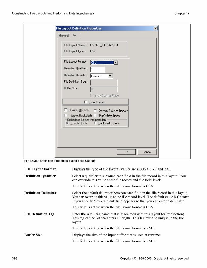
Constructing File Layouts and Performing Data Interchanges Chapter 17
File Layout Definition Properties dialog box: Use tab
File Layout Format Displays the type of file layout. Values are FIXED, CSV, and XML.
Definition Qualifier Select a qualifier to surround each field in the file record in this layout. Youcan override this value at the file record and file field levels.This field is active when the file layout format is CSV.
Definition Delimiter Select the default delimiter between each field in the file record in this layout.You can override this value at the file record level. The default value is Comma.If you specify Other, a blank field appears so that you can enter a delimiter.This field is active when the file layout format is CSV.
File Definition Tag Enter the XML tag name that is associated with this layout (or transaction).This tag can be 30 characters in length. This tag must be unique in the filelayout.
This field is active when the file layout format is XML.
Buffer Size Displays the size of the input buffer that is used at runtime.This field is active when the file layout format is XML.
398 Copyright © 1988-2006, Oracle. All rights reserved.
Chapter 17 Constructing File Layouts and Performing Data Interchanges
Note. Do not edit this value directly.
Imply Decimal Place Select to automatically add a decimal place based on the decimal value that isspecified in the field definition when importing a file into a PeopleSoftdatabase and no decimal place is specified for numeric values in the file.If you select this option, make sure that the length that you specify for theNumber field includes the decimal point, even though it is not visible. In thiscase, the decimal point is counted as a space.This field is active when the file layout format is FIXED.
Excel Format Select to parse the field by using Microsoft Excel CSV specifications.This field is active when the file layout format is CSV.
Qualifier Optional Select to parse the field based on delimiters. When a qualifier exists, the fieldis parsed by using a closing matched qualifier. All characters are ignoredbefore and after the qualifier.This field is active when the file layout format is CSV.If you do not select this check box, the field must have qualifier pairs. Allcharacters are ignored before and after the qualifier.
Convert Tabs to Spaces Select to convert all tabs within the field to spaces. If you do not select thisoption, all tabs are ignored.This field is active when the file layout format is CSV.
Note. If the Strip White Space option is also selected, the system removestrailing and leading tabs.
Interpret Backslashes Select to interpret backslashes within field data as escape characters.
The following characters have special meanings:
• \t represents a tab.• \n represents a new line.If you do not select this check box, backslashes are considered regular text data.This field is active when the file layout format is CSV.
Strip White Space Select to remove all leading and trailing white space within field data fromthe output data.This field is active when the file layout format is CSV.
Note. If you select this option, trailing and leading tabs are also removed,regardless of whether you have selected the Convert Tabs to Spaces option.
Double Quote Select to interpret two double quotes (" "), as one double quote (") in outputdata.For example, if you enable this option, abc""def" is interpreted asabc"def.
This field is active when the file layout format is CSV.
Copyright © 1988-2006, Oracle. All rights reserved. 399

Constructing File Layouts and Performing Data Interchanges Chapter 17
Backslash Quote Select to interpret backslash quotes (\") as one double quote (") in output data.For example, if you enable this option, "abc\"def" is interpreted asabc"def.
This field is active when the file layout format is CSV.
See AlsoChapter 17, “Constructing File Layouts and Performing Data Interchanges,” Understanding File Layouts,page 387
Specifying File Record PropertiesThe File Layout Segment Properties dialog box contains information that is stored at the file record level.
Access the dialog box by using one of the following methods:
• Double-click the file record node.• Right-click the file record node, and select Selected Node Properties.
File Record Name Enter a file record name that is associated with this file record. This name isused when accessing the file record from PeopleCode. Every file record in afile layout must have a unique name.
ID Seq No.(CSV)(identificationsequence number)
Enter a sequence number for the field that contains the file record ID.
Max Rec Length(maximumrecord length)
Displays the default maximum length of the combined field sizes of the record.This value is automatically updated.
Warning! Any inbound or outbound data is truncated beyond this value.
File Record ID Enter a number to uniquely identify the file record in the file layout. Youcan use this number in processing the file. This number is automaticallywritten to the file if you use the WriteRecord or WriteRowset methods andif the file type is FIXED or CSV.
ID Start Position (FIXED) Enter the column or starting position in the file record where the file recordID starts.
ID Length (FIXED, CSV) Displays the length of the file record ID. This number is automaticallygenerated when you enter the file record ID.
Note. This value shouldn’t be edited directly.
Default Qualifier (CSV) Enter a qualifier that is used for the file record ID and as the default forfields when no field qualifier is specified. This value overrides the definitionqualifier that is specified in the File Layout Definition Properties dialog box.When you first create a file layout, this property is blank.
Seg Terminator (FIXED,CSV)
Enter characters to be placed at the end of each segment when the layoutis written to a file.
400 Copyright © 1988-2006, Oracle. All rights reserved.

Chapter 17 Constructing File Layouts and Performing Data Interchanges
Field Delimiter (CSV) Enter a delimiter that is used for all fields in the file record. This overwritesthe definition delimiter that is specified on the File Layout DefinitionProperties dialog box.
Record Tag (XML) Enter an XML tag name for this file record. The default value is the filerecord name.
Note. Although each record name in a file layout must be unique, record tagsdo not have to be unique.
Record Description Enter a description of the record for documentation purposes only.
Specifying File Layout Field PropertiesThe File Layout Field Properties dialog box contains information that is stored at the file field level.
Access the dialog box by using one of the following methods:
• Double-click the file field node.• Right-click the file field node, and select Selected Node Properties.
Most individual properties are usable by all field types. However, some are specific to a particular fieldtype—for example, the Upper Case check box is applicable for character fields only, while the Date Separatorfield is applicable for date fields only, and so on. The preceding dialog box shows the properties for a charactertype of field. However, the following descriptions include all possible properties.
Field Name Enter the name that is associated with this file field. This name is used whenaccessing the file field from PeopleCode. Every field within a file recordmust have a unique name; however, two different file records can containthe same file field.
UpperCase (Char) Select to convert lowercase text to uppercase during inbound processing. Thisis used primarily when customer data may be in lowercase and the PeopleSoftsoftware requires the data to be in uppercase.
Field Type Select the data type of the file field.
Date Format (Date) Select a date format, such as MMDDYY, DDYYMM, and so on.
Date Separator (Date) Enter a character that is used to separate date values. The default value is /.
Decimal Position Enter the number of decimal positions (to the right) of the decimal point. Thisproperty is valid only for fields that are defined as number or signed number.
Note. You’re allowed only 31 characters plus a decimal point.
Field Length Enter the maximum number of characters of this field.
Note. You’re allowed only 32–character precision for number and signednumber fields, that is, a total of 32 characters both to the right and left of thedecimal. Other fields, such as character fields, can be longer.
You can’t set the field length for Date, Time, and Datetime type fields. Thesefield lengths are automatically set to the ISO standards for such fields.
Copyright © 1988-2006, Oracle. All rights reserved. 401

Constructing File Layouts and Performing Data Interchanges Chapter 17
Start Position (FIXED) Enter the starting position (column) of the field within the file record.
Important! If you specify a start position for a field that overwrites a previousfield, no data is written to the file. Use Propagate to change the start positionsfor your file fields.
Propagate (FIXED) If a field position or length is changed, enter an amount here to increment(positive number) or decrement (negative number) the current field and allfields before it ( <<< ) or after it (>>>).
Field Qualifier (CSV) Enter the qualifier for the field, that is, the character that surrounds this field,separating it from other fields. Specifying this value overwrites the value thatis specified in the file layout properties and file record properties.
Field Tag (XML) Enter an XML tag name to be used around the field. The default value is thename of the field.
Note. Although each field name in a file record must be unique, each field tagdoes not have to be unique.
Strip Characters Specify any characters to be removed from the input buffer. Use this topreprocess input strings. For example, if a field in the input file containshyphens, but you want to remove the hyphens before processing the field, youcan enter a hyphen here, and it is stripped out while being read. You can specifymore than one character to be stripped out. Be sure to not separate the stripcharacters. For example, the following strips out all semicolons and hyphens:
;-
The following strips out all semicolons, hyphens, and spaces:
; -
Trim Spaces Select to remove trailing spaces only from the input string. This option isactive only for FIXED and CSV formats.This is different from the Strip Characters field, which removes all spacesfrom the entire input field if you specify a space.
Pad Field (CSV) Select to enable field padding. The field will be padded with space charactersup to the value of the length property. Character data will be left justified,numeric data right justified.
Field Description Enter a description of the field for documentation purposes only.
Field Inheritance Optionally select a parent file record and field, from which the current field’svalue is to be inherited. If you’re writing to a file, this means that the value iswritten only in the parent file record, not in the child (inheriting) file record(that is, the value isn’t written more than once to a file). If no value is presentin the parent field, the default value that is specified here is used.For example, the following file sample shows both the EMPLID (8113) andEFFDT (08/06/1999) written only once to a file, though these fields arerepeated in the third file record (with a file record ID of 102):
100 8113 Frumman,Wolfgang
101 08/06/1999 000001 219 Going to London office
402 Copyright © 1988-2006, Oracle. All rights reserved.
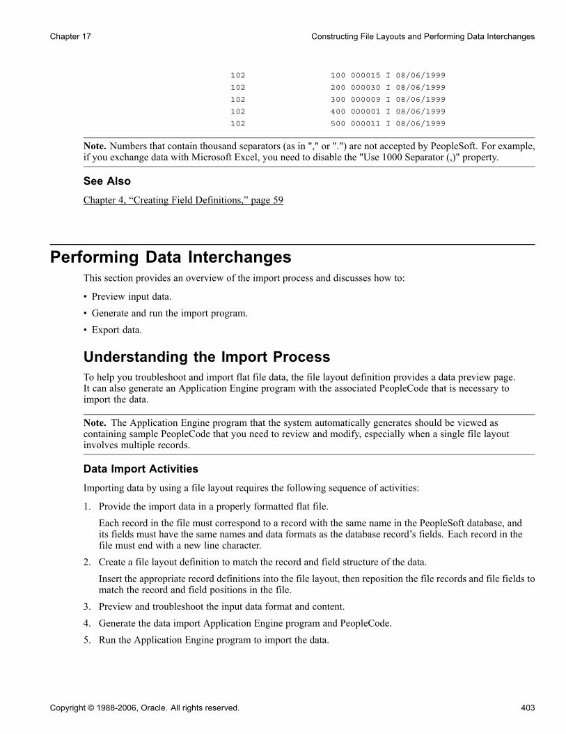
Chapter 17 Constructing File Layouts and Performing Data Interchanges
102 100 000015 I 08/06/1999
102 200 000030 I 08/06/1999
102 300 000009 I 08/06/1999
102 400 000001 I 08/06/1999
102 500 000011 I 08/06/1999
Note. Numbers that contain thousand separators (as in "," or ".") are not accepted by PeopleSoft. For example,if you exchange data with Microsoft Excel, you need to disable the "Use 1000 Separator (,)" property.
See AlsoChapter 4, “Creating Field Definitions,” page 59
Performing Data InterchangesThis section provides an overview of the import process and discusses how to:
• Preview input data.• Generate and run the import program.• Export data.
Understanding the Import ProcessTo help you troubleshoot and import flat file data, the file layout definition provides a data preview page.It can also generate an Application Engine program with the associated PeopleCode that is necessary toimport the data.
Note. The Application Engine program that the system automatically generates should be viewed ascontaining sample PeopleCode that you need to review and modify, especially when a single file layoutinvolves multiple records.
Data Import ActivitiesImporting data by using a file layout requires the following sequence of activities:
1. Provide the import data in a properly formatted flat file.
Each record in the file must correspond to a record with the same name in the PeopleSoft database, andits fields must have the same names and data formats as the database record’s fields. Each record in thefile must end with a new line character.
2. Create a file layout definition to match the record and field structure of the data.
Insert the appropriate record definitions into the file layout, then reposition the file records and file fields tomatch the record and field positions in the file.
3. Preview and troubleshoot the input data format and content.
4. Generate the data import Application Engine program and PeopleCode.
5. Run the Application Engine program to import the data.
Copyright © 1988-2006, Oracle. All rights reserved. 403
Constructing File Layouts and Performing Data Interchanges Chapter 17
Field Inclusion and ExclusionThe fields in the data file’s records can be a subset of the database record’s fields—define your file layoutwith only the file fields that you expect to receive.
The fields in the data file’s records can be a superset of the database record’s fields; you must define yourfile layout to suppress or ignore the extra fields. For FIXED files, don’t define a field at the correspondingposition in the file layout definition. For CSV files, the file layout must have the same number of fields ineach record as there are in the corresponding file record—for each field that you don’t want to import, definea field in the file layout at that position that doesn’t correspond to any field in that database record. ForXML files, any extra fields are ignored automatically.
Your data file can contain a subset or a superset of the records that are defined in the file layout. Only a filerecord with a matching file record ID in the file layout is imported.
Record HierarchyIn theory, you can ignore rowset hierarchy when importing file data, because the PeopleSoft database storeseach record independently of the others, and rowsets aren’t used in the import process. However, many recordsare designed with hierarchical dependencies in mind. The input file might omit inherited field values or orderthe data records in a way that reflects such dependencies.
If the input file omits inherited field values, make sure that the inheriting fields’ records in the file layout arechildren of the ones from which they inherit their values, and make the appropriate Field Inheritance settings.
If the records to be imported contain key fields that reflect a rowset hierarchy, they might be in an order in thefile that also reflects the hierarchy. Make sure your file layout reflects that hierarchy, as well.
Important! The completed file layout must have exactly one file record at the root level; all other filerecords must be below that level.
See AlsoChapter 17, “Constructing File Layouts and Performing Data Interchanges,” Reordering File Layout Nodes,page 395
Previewing Input DataIn PeopleSoft Application Designer, select File, New, File Layout, Preview.
404 Copyright © 1988-2006, Oracle. All rights reserved.

Chapter 17 Constructing File Layouts and Performing Data Interchanges
File layout preview
Initially no information is displayed on the preview tab.
Note. With an XML file, the data can’t be previewed, although you can still generate and run an importprogram.
To preview the input data:
1. Click Browse and select the import file.The name of the import file appears in the Import File text box.
2. Select a file layout segment from the Segment drop-down list box.The file layout fields corresponding to the selected segment appear in the list below the segment name.This list comes from the file layout definition, and does not depend on you selecting a valid import file.
3. Click the Refresh button on the toolbar to refresh the preview data.At the bottom of the window, a preview of the first five rows of the selected segment in the selectedimport file appears in the grid.You can also select View, Automatically Read Preview Data. While this menu item is selected, the filelayout refreshes the preview automatically; when it’s cleared, you need to click the Refresh Preview Databutton to see the effects of changes you make to the property settings or data.
Copyright © 1988-2006, Oracle. All rights reserved. 405

Constructing File Layouts and Performing Data Interchanges Chapter 17
Note. Preview file data is available only for FIXED and CSV file layouts. The preview data appears only ifyou’ve selected an import file, if the file format matches the format specified for the file layout definition,and if it contains a file record ID that matches the file record ID of the selected segment.
4. Select one of the fields on the Field Name list.The properties of the field that you selected appear in the appropriate display fields. These properties areactually the field’s file layout field properties; you can change all field property settings from this view.
Note. Only the field properties that are appropriate to the file layout format that you specified in the FileLayout Definition Properties dialog box are visible in this view; for example, the Start Position and FieldLength fields are available only for a FIXED format file layout.
Examining the Input Data for ErrorsThe following table shows some examples of input data errors:
Symptom Possible Reason Solution
The preview grid doesn’t appear. The input file’s format doesn’tmatch the file layout format thatyou specified in the File LayoutDefinition Properties dialog box.
A CSV file doesn’t use the definitionqualifier you specified in the FileLayout Definition Properties dialogbox.
Change the file layout format tomatch the input file.
Change the definition qualifier tomatch the one that is used in theinput file.
Only the first column of the previewgrid is populated.
A CSV file doesn’t use the definitiondelimiter you specified in the FileLayout Definition Properties dialogbox.
Change the definition delimiter tomatch the one that is used in theinput file.
The preview grid appears for somerecords, but not for others.
The file’s record IDs for the missingrecords don’t match their file recordIDs specified in the File LayoutSegment Properties dialog box.
Specify file record IDs that matchthe input file records.
Data for a field appears truncated inthe preview grid.
With a FIXED file, the field lengththat you specified in the File LayoutField Properties dialog box is tooshort to accommodate the field data.
Increase the field length toaccommodate the input data.
A field appears to start in the middleof the data.
With a FIXED file, the start positionyou specified in the File LayoutField Properties dialog box is toogreat to include the start of the fielddata.
Decrease the start position andadjust the field length to match theinput data start position and length.
406 Copyright © 1988-2006, Oracle. All rights reserved.

Chapter 17 Constructing File Layouts and Performing Data Interchanges
Generating and Running the Import ProgramThis part of the process imports the file data.
To generate and run the import program:
1. After you preview the file layout and examine the input data, click the AE button on the toolbar.This generates the Application Engine import program with its associated import PeopleCode.
2. Enter a name for the Application Engine program, and click OK.The program is automatically saved and is ready to run as soon as its definition appears in PeopleSoftApplication Designer.
3. Click the Run Program button on the toolbar.The file data is imported into the database.
Exporting DataThe method that you use to export data from the PeopleSoft system depends on the target application’srequirements. To export data to a flat file, you create a file layout definition, then write PeopleCode to transferthe data to a file. The PeopleCode can be initiated from Application Engine or from any event. It shouldpopulate text strings, rowset objects, or record objects, and it should apply the WriteRecord or WriteRowsetmethod from the File class to transfer the data to the file by using the file layout definition to position therecords and fields as required by the target application.
Note. To generate valid XML files, be sure to use the Close method in the File class when you finish writingto the file.
See AlsoEnterprise PeopleTools 8.48 PeopleBook: PeopleCode API Reference, “File Class”
Producing a Sample File LayoutThis section describes how to:
• Create the file layout definition.
• Adjust file layout properties.
• Insert a segment and a field.
Creating the File Layout DefinitionThis example illustrates how to create a file layout that can be used with the QE_ABSENCE_HIST record:
Copyright © 1988-2006, Oracle. All rights reserved. 407

Constructing File Layouts and Performing Data Interchanges Chapter 17
QE_ABSENCE_HIST record definition
For simplicity, suppose that each row in the FIXED format file has the following structure:
888 A
000 8001 VAC 1981-09-12 1981-09-26 14 .0 P Y
888 A
000 8001 VAC 1983-03-02 1983-03-07 5 .0 P Y
888 A
000 8001 VAC 1983-08-26 1983-09-10 13 .0 P Y
888 A
000 8516 MAT 1986-06-06 1986-08-01 56 .0 P Y
888 C
000 8516 SCK 1988-08-06 1988-08-07 1 .0 P Y
888 A
000 8516 VAC 1987-07-14 1987-07-28 14 .0 P Y
888 A
000 8553 JUR 1990-12-12 1990-12-17 5 .0 Local Jury Duty P N
888 A
000 8553 MAT 1992-02-20 1992-10-01 224 .0 Maternity Leave U N
888 A
000 8553 MAT 1994-08-19 1995-03-01 194 .0 Maternity U Y
888 A
000 8553 PER 1993-04-15 1993-04-19 4 .0 U N Personal
Day required
888 C
000 8553 SCK 1987-01-28 1987-01-30 2 .0 Hong Kong Flu P N
888 A
000 8553 SCK 1988-08-02 1988-08-03 1 .0 Sick P N
888 A
000 8553 SCK 1995-09-12 1995-09-13 1 .0 P N
888 C
000 G001 MAT 1991-07-02 1991-09-28 88 .0 3-month Maternity P Y Maternity will
be paid as 80% of Claudia’s current salary.
408 Copyright © 1988-2006, Oracle. All rights reserved.
Chapter 17 Constructing File Layouts and Performing Data Interchanges
000 is the file record ID for ABSENCE_HIST, and each field appears in the same order as in theABSENCE_HIST database record. 888 is the file record ID for an extra segment called CHANGE_ACTION,containing an AUDIT_ACTION field with the following meanings:
• A: Row inserted.
• C: Row updated, but no key fields changed.
Note. The end of file (EOF) character must be on a separate line and not on a line containing data for anyincoming file, regardless of the file type. Each data line needs to be terminated with an end of line (EOL)character, which is different from an EOF.
To create a file layout definition:
1. Use the QE_ABSENCE_HIST record definition as a template for the file layout.
Create a new file layout, then drag the QE_ABSENCE_HIST record into the open file layout.
2. Save the file layout.
Save it with a name of ABS_HIST.
The name of the first node changes from NEW FILE to ABS_HIST.
Adjusting File Layout PropertiesIn the file layout definition, open the file layout, record, or field properties as appropriate for each step inthe following procedure.
To adjust layout, record, and field properties:
1. Change the file layout properties.Double-click the topmost node in the file layout, ABS_HIST, to display the file layout properties.Enter a short and long description of the file layout you’re creating. For this example, we’re creating aFIXED file layout, so you don’t need to make any changes on the Use tab.
2. Change the file record properties.Double-click the QE_ABSENCE_HIST file record to display its properties. Enter a record ID of 000, anda starting position of 1. The ID length is automatically set.When you click OK, you see a message asking if you want to increment the start positions for all fields.Click Yes. This automatically increments the start position numbers for every field to take the length ofthe file record ID that you just added into account. If you don’t click Yes, you must manually incrementthe start position for all fields.You’ve just created the file record ID for the QE_ABSENCE_HIST record:
000 8001 VAC 1981-09-12 1981-09-26 14 .0 P Y
000 8001 VAC 1983-03-02 1983-03-07 5 .0 P Y
3. Change the file field properties.When a record definition is used as a template for a file layout, the default starting position for each field isbased on the order in which it appears in the record as well as its length.Double-click the QE_EMPLID file field to display its properties.
Copyright © 1988-2006, Oracle. All rights reserved. 409
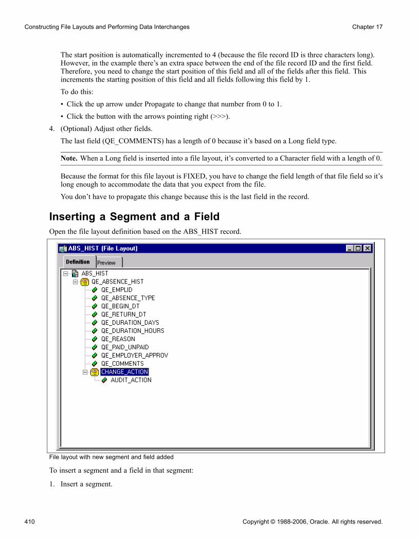
Constructing File Layouts and Performing Data Interchanges Chapter 17
The start position is automatically incremented to 4 (because the file record ID is three characters long).However, in the example there’s an extra space between the end of the file record ID and the first field.Therefore, you need to change the start position of this field and all of the fields after this field. Thisincrements the starting position of this field and all fields following this field by 1.To do this:• Click the up arrow under Propagate to change that number from 0 to 1.• Click the button with the arrows pointing right (>>>).
4. (Optional) Adjust other fields.The last field (QE_COMMENTS) has a length of 0 because it’s based on a Long field type.
Note. When a Long field is inserted into a file layout, it’s converted to a Character field with a length of 0.
Because the format for this file layout is FIXED, you have to change the field length of that file field so it’slong enough to accommodate the data that you expect from the file.You don’t have to propagate this change because this is the last field in the record.
Inserting a Segment and a FieldOpen the file layout definition based on the ABS_HIST record.
File layout with new segment and field added
To insert a segment and a field in that segment:
1. Insert a segment.
410 Copyright © 1988-2006, Oracle. All rights reserved.

Chapter 17 Constructing File Layouts and Performing Data Interchanges
Insert a segment that is a sibling, (that is, at the same level), as the QE_ABSENCE_HIST record. Inserta segment by selecting Insert Segment from the pop-up menu, or by selecting Insert, Segment. TheInsert New Segment dialog box appears.This dialog box is identical to the File Layout Segment Properties dialog box. Enter the file record name,file record ID, and ID start position. When you click OK, the segment is inserted.
Note. If you provide a Record File ID when adding a segment to a file layout that is either CSV or fixed,the system prepends this Record File Id to every row of data that gets written.
2. Insert a file field.Insert a file field by selecting Insert FileField from the pop-up menu. The Insert New Field dialog boxappears. It’s identical to the File Layout Field Properties dialog box. Enter the field name, start position,and field length; then click OK.
Note. The start position isn’t automatically set when you add a file field to the file record; for this examplethe AUDIT_ACTION field requires a start position of 5.
3. Save your work.
Be sure to save the changes that you’ve made to the file layout by selecting File, Save, or clicking thesave icon in the toolbar.
Now that you’ve created and saved a file layout, you must use PeopleCode to access the data. File layoutsrely solely on PeopleCode as the engine behind the actual data access and movement.
See AlsoEnterprise PeopleTools 8.48 PeopleBook: PeopleCode API Reference, “File Class”
Copyright © 1988-2006, Oracle. All rights reserved. 411

Constructing File Layouts and Performing Data Interchanges Chapter 17
412 Copyright © 1988-2006, Oracle. All rights reserved.

CHAPTER 18
Using Command Line Parameters
This chapter provides an overview of PeopleSoft Application Designer command line parameters and discusses how to:
• Start PeopleSoft Application Designer and PeopleSoft Data Mover.• Build projects.• Copy definitions.• Compare definitions.
Understanding PeopleSoft Application DesignerCommand Line Parameters
PeopleSoft Application Designer offers a variety of command-line parameters that you can use to controlthe database to which it connects. By using these parameters, you can automatically navigate to the partof the system that you need.
Use the values from the following tables when specifying certain parameters.
SyntaxThe following command line syntax applies to all actions identified in this chapter:
PSIDE [-parameter value [-parameter value . . .]]
You can include as many or as few parameters as you need.
Each parameter starts with a hyphen (-) or a forward slash (/). The value for each parameter follows the hyphenor slash, separated by zero or more spaces. In general, the value doesn’t need to have quotation marks aroundit, even if it has internal spaces—the system treats all text following the parameter as part of the value, up tothe next parameter or the end of the command line.
Note. You must enclose a value in quotation marks only when it includes a hyphen or forward slash, or toinclude leading or trailing spaces. If the value itself includes a quotation mark character, precede the doublequote with a backslash (\).
See AlsoEnterprise PeopleTools 8.48 PeopleBook: Data Management, “Using PeopleSoft Data Mover,” Using thePeopleSoft Data Mover Command-Line Interface
Copyright © 1988-2006, Oracle. All rights reserved. 413
Using Command Line Parameters Chapter 18
Starting PeopleSoft Application Designer CommandLine Interface
Use the command line syntax and available parameters to start PeopleSoft Application Designer.
Command Line SyntaxUse the command line syntax described previously to start PeopleSoft Application Designer.
See Chapter 18, “Using Command Line Parameters,” Understanding PeopleSoft Application DesignerCommand Line Parameters, page 413.
Available ParametersThe available parameters for PSIDE.EXE fall into two general categories:
• Parameters providing login information.• Parameters setting general options.
This table lists all of the available parameters:
Parameter Value Description
-CT Database type Enter the type of database to whichyou are connecting. Valid values areORACLE, INFORMIX, SYBASE,MICROSFT, DB2ODBC, andDB2 UDB for Linux, UNIX, andMicrosoft (note the spelling ofMICROSFT).
-CS Server name Enter the name of the databaseserver for the database that you’reconnecting to. This setting isrequired for some database types.
-CD Database name Enter the name of the database towhich you are connecting, as youwould enter it into the PeopleSoftLogin dialog box.
-CO User ID Enter the PeopleSoft user ID to login with.
-CP Password Enter the password for the specifieduser ID.
-CI Connect ID Enter the ID that is used to connectto the database server.
414 Copyright © 1988-2006, Oracle. All rights reserved.

Chapter 18 Using Command Line Parameters
Parameter Value Description
-CW Password Enter the password for the specifiedconnect ID.
-SS NO Use to suppress the display of thePeopleSoft splash screen. Any othervalue causes the splash screen todisplay.
-SN NO Use to suppress the sound that playswhen you sign in to the PeopleSoftsystem. Any other value causes thesound to play.
-QUIET (none) Use to run in quiet mode, so that nomessage boxes appear. The systemwrites messages to the log file ortrace file depending on whether youalso use the -LF parameter. Quietmode is recommended for use withprocesses that require no humaninteraction.
-HIDE (none) Use to hide the PeopleSoftApplication Designer interface.
-LF Log file path name Path to the log file when used inconjunction with the -QUIETparameter. If used, the system writesany messages generated duringprocessing to the log file.
-FP Filename (PeopleSoft Data Mover only) Enterthe name of the Data Mover script torun.
ExampleThis command line statement starts PeopleSoft Application Designer and signs in to the DEP7TST database:
PSIDE -CT MICROSFT -CS SEPNTDB05 -CD EP7TST -CO VP1 -CP VP1
Building ProjectsUse the same command line syntax as identified previously to build a project.
Copyright © 1988-2006, Oracle. All rights reserved. 415

Using Command Line Parameters Chapter 18
See Chapter 18, “Using Command Line Parameters,” Understanding PeopleSoft Application DesignerCommand Line Parameters, page 413.
Use the command line statement for the project build to:
• Connect the project to the source database.• Use the build settings from the Windows registry to generate the SQL script for the create or alter processes.
Before running the build command line, verify that:
• The project’s system components are created and loaded.
• The build options are set in the Windows registry.
Available ParametersThis table lists all of the available parameters for the project build statement:
Parameter Description Error Handling
-HIDE Use to hide the PeopleSoftApplication Designer interface.Always use this parameter whenperforming a command line Copyprocess.
Required for all project commandline processes.
-CT Database type.
Enter the type of the databaseto which you are connecting(MICROSFT, ORACLE, SYBASE,and so on).
Required. If you do not supply thisparameter, the last database type istaken from the registry. If it fails, theprocess stops and error messages arewritten to the log file.
-CS Server name.
Enter the name of the sourcedatabase server for the database towhich you are connecting.
Required for some database types. Ifyou do not supply this parameter, theprocess stops and error messages arewritten to the log file.
-CD Database name.
Enter the name of the sourcedatabase to which you areconnecting, as you would enterit into the PeopleSoft Login dialogbox.
Required. If you do not supply thisparameter, the process stops anderror messages are written to the logfile.
-CO User ID.
Enter the PeopleSoft user ID thatis needed to sign in to the sourcedatabase.
Required. If you do not supply thisparameter, the last database type istaken from the registry. If it fails, theprocess stops and error messages arewritten to the log file.
416 Copyright © 1988-2006, Oracle. All rights reserved.

Chapter 18 Using Command Line Parameters
Parameter Description Error Handling
-CP User password.
Enter the password for the specifieduser ID for the source database.
Required. If you do not supplythis parameter, a PeopleSoft Logindialog box appears for the user toenter a valid user password. If thepassword fails, the process stops anderror messages are written to the logfile.
-PJB Project name.
Enter the name of the project tobe built. This project should beavailable in the database beforestarting the command line projectbuild.
Required. This is the mainparameter and is used internallyto decide whether the user canbuild a project. If you do not supplythis parameter and if you supplyall of the source database loginparameters, the program only startsthe application.
ExampleFor this example, assume that the:
• Project name is CJR1.• Database type is Microsoft.• Database name is CJR810G.• User ID is PTDMO.• Password is PTDMO.• Path name of the SQL script file is c:\temp\psbuild.sql.• Path name of the log file is c:\temp\psbuild.log in the Windows registry.
For this example, you would enter the following at the command line:
PSIDE.EXE −CT MICROSFT −CD CJR810G −CO PTDMO −CP PTDMO −PJB CJR_PRJ -HIDE -QUIET
Copying DefinitionsUse the same command line syntax as identified previously to copy definitions.
See Chapter 18, “Using Command Line Parameters,” Understanding PeopleSoft Application DesignerCommand Line Parameters, page 413.
Use the command line statement for Upgrade Copy processes to:
• Connect to the source database.
• Connect to the target database.
• Copy the project and its objects from the source database to the target database.
Copyright © 1988-2006, Oracle. All rights reserved. 417
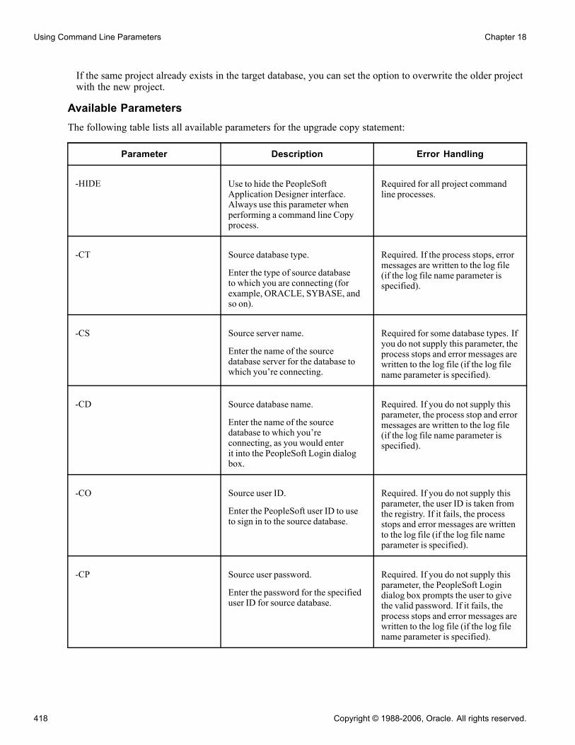
Using Command Line Parameters Chapter 18
If the same project already exists in the target database, you can set the option to overwrite the older projectwith the new project.
Available ParametersThe following table lists all available parameters for the upgrade copy statement:
Parameter Description Error Handling
-HIDE Use to hide the PeopleSoftApplication Designer interface.Always use this parameter whenperforming a command line Copyprocess.
Required for all project commandline processes.
-CT Source database type.
Enter the type of source databaseto which you are connecting (forexample, ORACLE, SYBASE, andso on).
Required. If the process stops, errormessages are written to the log file(if the log file name parameter isspecified).
-CS Source server name.
Enter the name of the sourcedatabase server for the database towhich you’re connecting.
Required for some database types. Ifyou do not supply this parameter, theprocess stops and error messages arewritten to the log file (if the log filename parameter is specified).
-CD Source database name.
Enter the name of the sourcedatabase to which you’reconnecting, as you would enterit into the PeopleSoft Login dialogbox.
Required. If you do not supply thisparameter, the process stop and errormessages are written to the log file(if the log file name parameter isspecified).
-CO Source user ID.
Enter the PeopleSoft user ID to useto sign in to the source database.
Required. If you do not supply thisparameter, the user ID is taken fromthe registry. If it fails, the processstops and error messages are writtento the log file (if the log file nameparameter is specified).
-CP Source user password.
Enter the password for the specifieduser ID for source database.
Required. If you do not supply thisparameter, the PeopleSoft Logindialog box prompts the user to givethe valid password. If it fails, theprocess stops and error messages arewritten to the log file (if the log filename parameter is specified).
418 Copyright © 1988-2006, Oracle. All rights reserved.
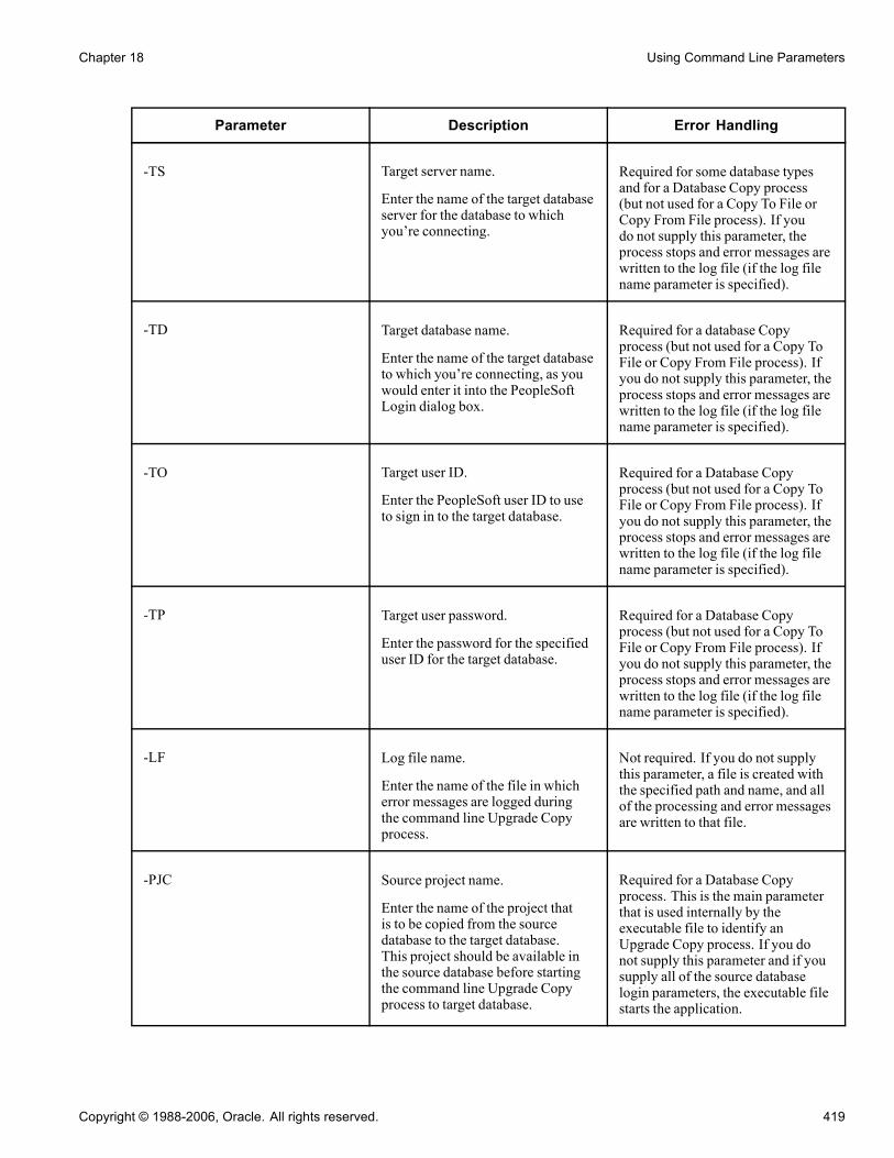
Chapter 18 Using Command Line Parameters
Parameter Description Error Handling
-TS Target server name.
Enter the name of the target databaseserver for the database to whichyou’re connecting.
Required for some database typesand for a Database Copy process(but not used for a Copy To File orCopy From File process). If youdo not supply this parameter, theprocess stops and error messages arewritten to the log file (if the log filename parameter is specified).
-TD Target database name.
Enter the name of the target databaseto which you’re connecting, as youwould enter it into the PeopleSoftLogin dialog box.
Required for a database Copyprocess (but not used for a Copy ToFile or Copy From File process). Ifyou do not supply this parameter, theprocess stops and error messages arewritten to the log file (if the log filename parameter is specified).
-TO Target user ID.
Enter the PeopleSoft user ID to useto sign in to the target database.
Required for a Database Copyprocess (but not used for a Copy ToFile or Copy From File process). Ifyou do not supply this parameter, theprocess stops and error messages arewritten to the log file (if the log filename parameter is specified).
-TP Target user password.
Enter the password for the specifieduser ID for the target database.
Required for a Database Copyprocess (but not used for a Copy ToFile or Copy From File process). Ifyou do not supply this parameter, theprocess stops and error messages arewritten to the log file (if the log filename parameter is specified).
-LF Log file name.
Enter the name of the file in whicherror messages are logged duringthe command line Upgrade Copyprocess.
Not required. If you do not supplythis parameter, a file is created withthe specified path and name, and allof the processing and error messagesare written to that file.
-PJC Source project name.
Enter the name of the project thatis to be copied from the sourcedatabase to the target database.This project should be available inthe source database before startingthe command line Upgrade Copyprocess to target database.
Required for a Database Copyprocess. This is the main parameterthat is used internally by theexecutable file to identify anUpgrade Copy process. If you donot supply this parameter and if yousupply all of the source databaselogin parameters, the executable filestarts the application.
Copyright © 1988-2006, Oracle. All rights reserved. 419

Using Command Line Parameters Chapter 18
Parameter Description Error Handling
-PJTF Copy Project To File project name.
Enter the name of the project to becopied from the source database tothe file.
Required for a Copy To File process.Do not include the file path to theproject with this parameter. Use -FPto specify the file path.
-PJFF Copy Project From File projectname.
Enter the name of the project to becopied from the file into the sourcedatabase.
Required for a Copy From Fileprocess. Do not include the file pathto the project with this parameter.Use -FP to specify the file path.
-FP Project file path.
Enter the path to the project for aCopy to File or Copy From Fileprocess.
Required for a Copy To File orCopy From File process (but notfor a Database Copy process). Forthe Copy From File process, thedirectory must exist. For the CopyTo File process, any project withthe same name is overwritten unlessyou use the -OVW parameter. Adirectory specification is created ifit does not exist. Do not include thename of the project in the file path.Use -PJTF or -PJFF to specify theproject name.
-OVD Override dependencies (0 or 1).
Enter 1 to override the checks forunapplied dependency incidentsduring the Copy From File processand to perform the copy even ifthe project’s dependency incidentshave not been applied to the sourcedatabase.
Not required, and not applicablefor processes other than the CopyFrom File process. The default is 0.When you enter the default and ifthe project’s dependency incidentshave not been applied to the sourcedatabase, an error message is writtento the log file listing which incidentsneed to be applied. The Copy FromFile process also stops. When youenter 1, a warning message is writtento the log for unapplied incidents andprocessing continues.
-CL Commit limit.
Enter the Commit limit (a numbergreater than 0) for the number ofobjects to be copied or comparedbefore a commit is issued. Example:-CL 150
Not required. The default is 50 if theuser does not set this parameter.
420 Copyright © 1988-2006, Oracle. All rights reserved.

Chapter 18 Using Command Line Parameters
Parameter Description Error Handling
-AF Audit flags on records (0 or 1).
Enter 1 to keep the target audit flagsas is. Enter 0 to take them from thesource database. Example: -AF 0
Not required. The default is 1.
-DDL Data definition language (DDL) onrecords and indexes (0 or 1).
Enter 1 to keep the target databaseDDL flags as is. Enter 0 to take themfrom the source database. Example:-DDL 0
Not required. The default is 1.
-PPL Portal registry structures permissionlist references.
Enter 1 to keep the target portalregistry permission list referencesas is. Enter 0 to take them from thesource database.
Not required. The default is 1.
-EXP Export project definition (0 or 1).
Enter 1 to export the projectdefinition to the target databasewhen using the Database Copyprocess. Not applicable for CopyProject to File process.
Not required. The default is 1.Any project with the same name isoverwritten with the new projectdefinition.
-OBJ Object types to copy
List the object types as numberswith commas as delimiters. Forexample, if you choose records andindexes alone for copying, use theappropriate numbers for records andindexes from the Definition TypeSelection table. For records, thenumber is 0, and for the indexes, thenumber is 1. Example: -OBJ 0,1
See Appendix B, “ReferencingSelections for Command LineParameters,” Definition TypeSelections, page 535.
Not required. If you do not supplythis parameter, then all of the objectsare copied by default.
-RST Reset done flags (0 or 1).
Enter 1 to reset the done flags beforeinitiating the Copy process. Enter 0to not reset them. Example: -RST 0
Not required. The default is 1.
Copyright © 1988-2006, Oracle. All rights reserved. 421

Using Command Line Parameters Chapter 18
Parameter Description Error Handling
-OVW Overwrite existing project (0 or 1).Enter 1 to overwrite any existingprojects with the same name inthe specified path during the CopyProject To File process, or in thedatabase in the Copy Project FromFile process. Enter 0 to not overwriteexisting projects. This applies tothe Copy Project To and From Fileprocesses only.
Not required. The default is 1.
-LNG Copy languages.
List the language codes withcommas as delimiters, or enter ALLto select all available languages.For new languages that are notlisted in the Language Selectiontable, use the xlat short name fromthe LANGUAGE_CD field in thetranslate table. For example, ifyou choose English and Spanishfor copying, enter the appropriatecodes for English and Spanish fromthe Language Selection table. ForEnglish, the code is ENG, and forSpanish, the code is ESP. Example:-LNG ENG,ESP
See Appendix B, “ReferencingSelections for Command LineParameters,” Language Selections,page 540.
Not required. If you do not supplythis parameter, then the languagesthat are already set in the project areused as the default. The COMMONlanguage code refers to nonlanguageattributes that are not translated.Translated attributes can be copiedseparately from nontranslatedattributes. If you do not specifythe COMMON code when using-LNG, you copy only the translatedlanguage attributes.
Changing languages on thecommand line changes the valuesthat are stored with the projectdefinition. Subsequent Copy andCompare processes on the modifiedproject use the new values unlessthey are explicitly changed again inthe upgrade options.
422 Copyright © 1988-2006, Oracle. All rights reserved.

Chapter 18 Using Command Line Parameters
Parameter Description Error Handling
-CFD Keep Target ChartField PageFieldDisplay Size.
(Number 1 or 0). This parameterindicates whether or not the targetchartfield page field display sizeattributes are to be kept, or whetherthey should be set from sourceduring copy. See Upgrade Optionsfor more information.
Enter 1 to keep the target chartfieldpage field display size attributes.
Enter 0 to set these attributes fromthe source values.
Not required. Default is 1
-CFF Keep Target ChartField FieldFormat.
(Number 1 or 0) This parameterindicates whether or not the targetchartfield field format attributes areto be kept, or whether they shouldbe set from the source during Copy.See Upgrade Options for moreinformation.
Enter 1 to keep the target chartfieldfield format attributes.
Enter 0 to set these attributes fromthe source values.
Not required. Default is 1
Example: Database Copy ProcessThese are some command line statements for the Database Copy process:
• Copy the project PPLTOOLS from the source Microsoft SQL Server database, PTDMO, to the targetdatabase, PTTST.
• Log process and error messages to c:\temp\copy.log.
• Set the commit limit to 150.
Copy the audit flags and record and index DDLs from the source database.
• Copy only records, indexes, pages, queries, and process definitions from the project.
• Do not reset the done flags before initiating the Copy process.
• Copy only English and Spanish translations.
PSIDE.EXE −HIDE -PJC PPLTOOLS -CT MICROSFT -CD PTDMO -CO PTDMO -CP PTDMO -TDPTTST -TO PTDMO -TP PTDMO -QUIET -LF C:\TEMP\COPY.LOG -CL 150 -AF 0 -DDL 0 -OBJ0,1,5,10,20 -RST 0 -LNG ENG, ESP
Copyright © 1988-2006, Oracle. All rights reserved. 423

Using Command Line Parameters Chapter 18
Example: Copy To File ProcessThese are some command line statements for the Copy to File process:
• Copy the PPLTOOLS project from the Oracle database, PTDMO, by using the PTDMO user ID, to thelocal directory c:\temp\export.A directory named PPLTOOLS is created in c:\temp\export.
• Log progress and error messages to c:\temp\copy.log.
PSIDE.EXE −HIDE -PJTF PPLTOOLS -FP c:\temp\export -CT ORACLE -CD PTDMO -CO PTDMO -CPPTDMO -QUIET -LF c:\temp\copy.log
Example: Copy From File ProcessThese are some command line statements for the Copy From File process.
• Copy the PPLTOOLS project to the DB2 UDB for Linux, Unix, and Windows database, PTDMO, by usingthe user ID PTDMO, from the local directory c:\temp\export.A directory named PPLTOOLS must exist under c:\temp\export.
• Log progress and error messages to c:\temp\copy.log.
PSIDE.EXE −HIDE -PJFF PPLTOOLS -FP c:\temp\export -CT DB2UNIX -CD PTDMO -CO PTDMO -CPPTDMO -QUIET LF c:\temp\copy.log
Comparing Definitions for Upgrade Using the Command LineUse the same command line syntax as identified previously to compare definitions.
See Chapter 18, “Using Command Line Parameters,” Understanding PeopleSoft Application DesignerCommand Line Parameters, page 413.
Use the command line statement for an Upgrade Compare process to:
• Connect to the source database.
• Connect to the target database.
• Perform a project or database compare (based on parameters).
• Create compare reports in the specified output directory.
Available ParametersThis table lists all of the available parameters for the upgrade compare statement:
424 Copyright © 1988-2006, Oracle. All rights reserved.

Chapter 18 Using Command Line Parameters
Parameter Description Error Handling
-HIDE Use to hide the PeopleSoftApplication Designer interface.Always use this parameter whenperforming a command lineCompare process.
Required for all project commandline processes.
-CT Source database type.
Enter the type of source databaseto which you’re connecting (forexample, ORACLE, SYBASE, andso on). Choose from the DatabaseType Selection table.
See Appendix B, “ReferencingSelections for Command LineParameters,” Database TypeSelections, page 535.
Required. If the process stops, errormessages are written to the log file(if the log file name parameter isspecified).
-CS Source server name.
Enter the name of the sourcedatabase server for the database towhich you’re connecting.
Required for some database types. Ifyou do not supply this parameter, theprocess stops and error messages arewritten to the log file (if the log filename parameter is specified).
-CD Source database name.
Enter the name of the sourcedatabase to which you areconnecting, as you would enterit into the PeopleSoft Login dialogbox.
Required. If you do not supply thisparameter, the process stops anderror messages are written to the logfile (if the log file name parameter isspecified).
-CO Source user ID.
Enter the PeopleSoft user ID to useto sign in to source database.
Required. If you do not supply thisparameter, the user ID is taken fromthe registry. If it fails, the processstops and error messages are writtento the log file (if the log file nameparameter is specified).
-CP Source user password.
Enter the password for the specifieduser ID for source database.
Required. If you do not supply thisparameter, the PeopleSoft Logindialog box prompts the user toenter the valid user password. If thepassword fails, the process tops errormessages are written to the log file(if the log file name parameter isspecified).
Copyright © 1988-2006, Oracle. All rights reserved. 425

Using Command Line Parameters Chapter 18
Parameter Description Error Handling
-TS Target server name.
Enter the name of the target databaseserver for the database to whichyou’re connecting.
Required for some database types. Ifyou do not supply this parameter, theprocess stops and error messages arewritten to the log file (if the log filename parameter is specified).
-TD Target database name.
Enter the name of the target databaseto which you are connecting, as youwould enter it into the PeopleSoftLogin dialog box.
Required. If you do not supply thisparameter, the process stops anderror messages are written to the logfile (if the log file name parameter isspecified).
-TO Target user ID.
Enter the PeopleSoft user ID to useto sign in to the target database.
Required. If you do not supply thisparameter, the process stops anderror messages are written to the logfile (if the log file name parameter isspecified).
-TP Target user password.
Enter the password for the specifieduser ID for the target database.
Required. If you do not supply thisparameter, the process stops anderror messages are written to the logfile (if the log file name parameter isspecified).
-LF Log file name.
Enter the name of the file in whicherror messages are logged during thecommand line Upgrade Compareprocess.
Not required. If you do not supplythis parameter, a file is created withthe specified path and name, and allof the error messages are written tothat file.
-PJM Source project name.
Enter the name of the project thatis to be compared from the sourcedatabase to the target database. Thisproject should be available in thesource database before starting thecommand line Upgrade Compareprocess to the target database.
Required. This is the mainparameter that is used internallyby the executable file to identifyan upgrade compare. If you do notsupply this parameter and if yousupply all of the source databaselogin parameters, this executable filestarts the application.
-CL Commit limit
Enter the Commit limit (a numbergreater than 0) for the number ofobjects to be copied or comparedbefore a commit is issued. Example:-CL 150
Not required. The default is 50.
426 Copyright © 1988-2006, Oracle. All rights reserved.

Chapter 18 Using Command Line Parameters
Parameter Description Error Handling
-AF Audit flags on records (0 or 1). Enter1 to keep the target audit flags as is.Enter 0 to take them from the sourcedatabase. Example: -AF 0
Not required. The default is 1.
-PPL Portal registry structures permissionlist references.
Enter 1 to keep the target portalregistry permission list referencesas is. Enter 0 to take them from thesource database. Example: -PPL 0
Not required. The default is 1.
-DDL DDL on records and indexes ( 0or 1). Enter 1 to keep the targetdatabase DDL flags as is. Enter 0 totake them from the source database.When keeping the target databaseDDL, no differences are shown onthe compare report. Example: -DDL0
Not required. The default is 1.
-CFD Chartfield PageField Display Size(0 or 1). Enter 1 to keep the targetdatabase chartfield pagefield displaysize attributes. Enter 0 to take themfrom the source database. Whenkeeping target database attributes,no differences are shown on thecompare report for these attributes.Example -CFD 0
Not required. The default is 1.
-CFF Chartfield Field Format (0 or 1).Enter 1 to keep the target databasechartfield field format attributes.Enter 0 to take them from the sourcedatabase. When keeping targetattributes, no differences are shownon the compare report for theseattributes. Example: -CFF 0
Not required. The default is 1.
-CMT Compare type: project (1) ordatabase (0). Example: -CMT 0
Not required. The default is 1.
-TGT Target Orientation: PeopleSoftvanilla (0) or keep personalization(1).
Not required. The default is 0.
Copyright © 1988-2006, Oracle. All rights reserved. 427

Using Command Line Parameters Chapter 18
Parameter Description Error Handling
-CBY Comparison By:
To compare by release, enterREL, followed by the releasenumber. To compare by date,enter DAT, followed by adate in the following format:YYYY-MM-DD-HH.MM.SS.sss.Release numbers are included inthe Available Release Numbers list.Example: 2002-02-01-12.00.00.000
Not required. The default is REL.
-ROD Report Output Directory.
Enter the report output directorylocation. Example-RODc:\temp\upgreports
Not required. If you do not supplythis parameter, the system uses theReport Output Directory value fromthe Tools, Options General tab.
-OBJ Definition type to compare
List the definition types to compareas numbers with commas asdelimiters, or enter All. Example:-OBJ 0,1
See Appendix B, “ReferencingSelections for Command LineParameters,” Definition TypeSelections, page 535.
Not required. If you do not supplythis parameter, then all of thedefinitions are compared by default.For a project comparison, this refersto all definitions in the project. Fora database comparison, this includesall definitions in the database. Forexample, If you choose records andindexes alone for copying, use theappropriate numbers for records andindexes from the Definition TypeSelection table. For records, thenumber is 0, and for the indexes, thenumber is 1.
428 Copyright © 1988-2006, Oracle. All rights reserved.
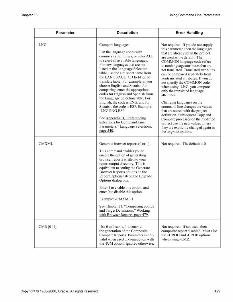
Chapter 18 Using Command Line Parameters
Parameter Description Error Handling
-LNG Compare languages.
List the language codes withcommas as delimiters, or enter ALLto select all available languages.For new languages that are notlisted in the Language Selectiontable, use the xlat short name fromthe LANGUAGE_CD field in thetranslate table. For example, if youchoose English and Spanish forcomparing, enter the appropriatecodes for English and Spanish fromthe Language Selection table. ForEnglish, the code is ENG, and forSpanish, the code is ESP. Example:-LNG ENG,ESP
See Appendix B, “ReferencingSelections for Command LineParameters,” Language Selections,page 540.
Not required. If you do not supplythis parameter, then the languagesthat are already set in the projectare used as the default. TheCOMMON language code refersto nonlanguage attributes that arenot translated. Translated attributescan be compared separately fromnontranslated attributes. If you donot specify the COMMON codewhen using -LNG, you compareonly the translated languageattributes.
Changing languages on thecommand line changes the valuesthat are stored with the projectdefinition. Subsequent Copy andCompare processes on the modifiedproject use the new values unlessthey are explicitly changed again inthe upgrade options.
-CMXML Generate browser reports (0 or 1).
This command enables you toenable the option of generatingbrowser reports written to yourreport output directory. This isequivalent to setting the GenerateBrowser Reports options on theReport Options tab on the UpgradeOptions dialog box.
Enter 1 to enable this option, andenter 0 to disable this option.
Example: -CMXML 1
See Chapter 21, “Comparing Sourceand Target Definitions,” Workingwith Browser Reports, page 479.
Not required. The default is 0.
-CMR [0 | 1] Use 0 to disable, 1 to enable,the generation of the CompositeCompare Reports. Parameter is onlyvalid when used in conjunction withthe -PJM option. Ignored otherwise.
Not required. If not used, thencomposite report disabled. Must alsouse –CROD and -CRDB optionswhen using -CMR.
Copyright © 1988-2006, Oracle. All rights reserved. 429

Using Command Line Parameters Chapter 18
Parameter Description Error Handling
-CROD [directory path] Set path for the Old ReleaseCompare reports when generatingComposite Reports (-CMR 1). Onlyvalid when used in conjunctionwith the -PJM and -CMR 1 options,ignored otherwise.
If not set when generating compositereports (-CMR 1) then its an errorcondition, and processing shouldstop, and an error generated tothe log file. Directory path canbe a local directory, a mappednetwork directory, or a UNC pathspecification.
-CRDB [database name] Pass the value of the Old ReleaseSource Database name whengenerating Composite Reports.This value must match the SourceDatabase name value from the OldRelease Report for each definitiontype. This is to ensure the originalold release report is valid andcontains the expected data. If the oldrelease report source database namefor the current definition type doesnot match the passed value, then anerror message is generated to the logfile, but process continues for otherdefinition types.
Not required.
Example: Running an Upgrade Compare ProcessUse this example as a guide for running an Upgrade Compare process:
• Run a database Compare process against the source Microsoft SQL Server database, PTDMO, and thetarget database, PTTST.
• Log process and error messages to c:\temp\compare.log.• Set the commit limit to 150.• Show the audit flag and DDL differences between databases.• Compare records, indexes, pages, queries, and process definitions.• Compare only English and Spanish translations.• Set the database compare type.• Set the target orientation to keep the customizations.• Compare by release 8.40.00.000.• Generate compare reports to the c:\temp\upgreports directory.
PSIDE.EXE −HIDE -CT MICROSFT -CD PTDMO -CO PTDMO -CP PTDMO -PJM PPLTOOLS -TDPTTST -TO PTDMO -TP PTDMO -QUIET -LF C:\TEMP\COMPARE.LOG -CL 150 -AF 0 -DDL 0 -OBJ0,1,5,10,20 -LNG ENG, ESP -CMT 0 -TGT 1 -CBY REL Core 8.40.00.000 -ROD C:\TEMP\UPGREPORTS
430 Copyright © 1988-2006, Oracle. All rights reserved.
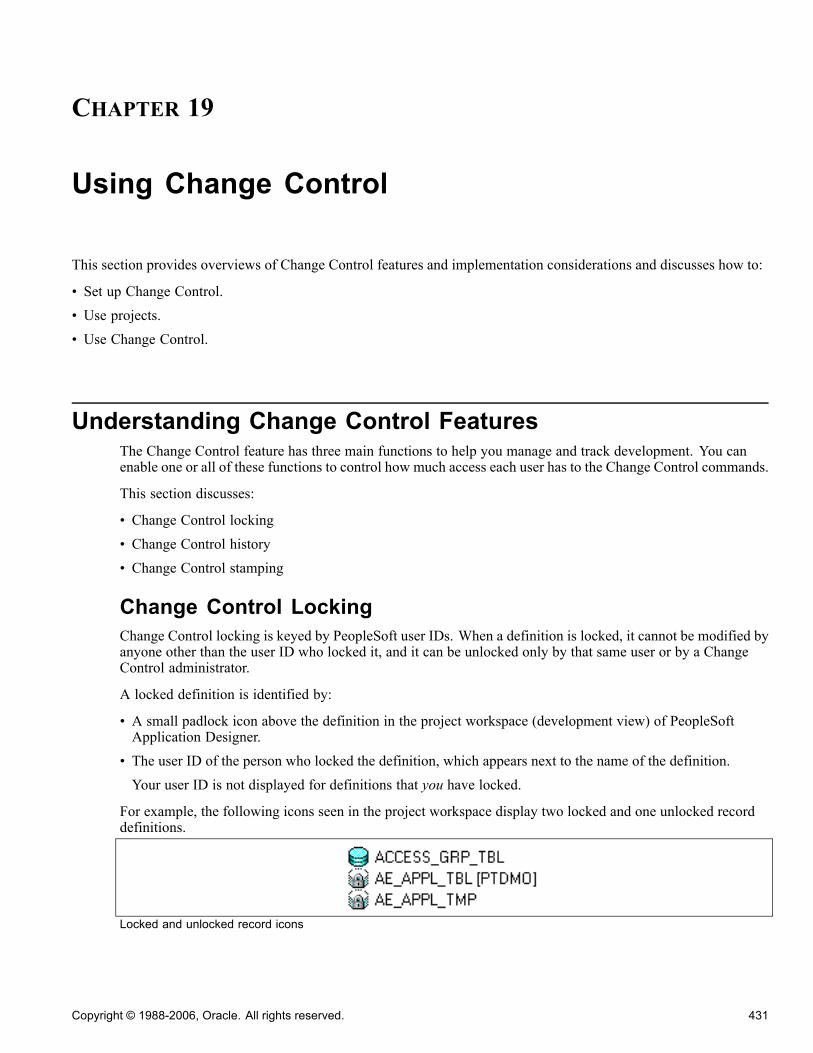
CHAPTER 19
Using Change Control
This section provides overviews of Change Control features and implementation considerations and discusses how to:
• Set up Change Control.• Use projects.• Use Change Control.
Understanding Change Control FeaturesThe Change Control feature has three main functions to help you manage and track development. You canenable one or all of these functions to control how much access each user has to the Change Control commands.
This section discusses:
• Change Control locking• Change Control history• Change Control stamping
Change Control LockingChange Control locking is keyed by PeopleSoft user IDs. When a definition is locked, it cannot be modified byanyone other than the user ID who locked it, and it can be unlocked only by that same user or by a ChangeControl administrator.
A locked definition is identified by:
• A small padlock icon above the definition in the project workspace (development view) of PeopleSoftApplication Designer.
• The user ID of the person who locked the definition, which appears next to the name of the definition.Your user ID is not displayed for definitions that you have locked.
For example, the following icons seen in the project workspace display two locked and one unlocked recorddefinitions.
Locked and unlocked record icons
Copyright © 1988-2006, Oracle. All rights reserved. 431
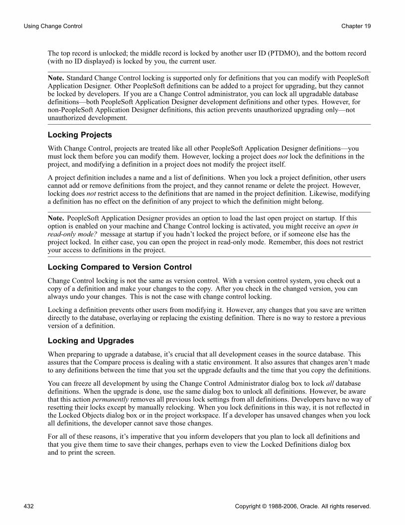
Using Change Control Chapter 19
The top record is unlocked; the middle record is locked by another user ID (PTDMO), and the bottom record(with no ID displayed) is locked by you, the current user.
Note. Standard Change Control locking is supported only for definitions that you can modify with PeopleSoftApplication Designer. Other PeopleSoft definitions can be added to a project for upgrading, but they cannotbe locked by developers. If you are a Change Control administrator, you can lock all upgradable databasedefinitions—both PeopleSoft Application Designer development definitions and other types. However, fornon-PeopleSoft Application Designer definitions, this action prevents unauthorized upgrading only—notunauthorized development.
Locking ProjectsWith Change Control, projects are treated like all other PeopleSoft Application Designer definitions—youmust lock them before you can modify them. However, locking a project does not lock the definitions in theproject, and modifying a definition in a project does not modify the project itself.
A project definition includes a name and a list of definitions. When you lock a project definition, other userscannot add or remove definitions from the project, and they cannot rename or delete the project. However,locking does not restrict access to the definitions that are named in the project definition. Likewise, modifyinga definition has no effect on the definition of any project to which the definition might belong.
Note. PeopleSoft Application Designer provides an option to load the last open project on startup. If thisoption is enabled on your machine and Change Control locking is activated, you might receive an open inread-only mode? message at startup if you hadn’t locked the project before, or if someone else has theproject locked. In either case, you can open the project in read-only mode. Remember, this does not restrictyour access to definitions in the project.
Locking Compared to Version ControlChange Control locking is not the same as version control. With a version control system, you check out acopy of a definition and make your changes to the copy. After you check in the changed version, you canalways undo your changes. This is not the case with change control locking.
Locking a definition prevents other users from modifying it. However, any changes that you save are writtendirectly to the database, overlaying or replacing the existing definition. There is no way to restore a previousversion of a definition.
Locking and UpgradesWhen preparing to upgrade a database, it’s crucial that all development ceases in the source database. Thisassures that the Compare process is dealing with a static environment. It also assures that changes aren’t madeto any definitions between the time that you set the upgrade defaults and the time that you copy the definitions.
You can freeze all development by using the Change Control Administrator dialog box to lock all databasedefinitions. When the upgrade is done, use the same dialog box to unlock all definitions. However, be awarethat this action permanently removes all previous lock settings from all definitions. Developers have no way ofresetting their locks except by manually relocking. When you lock definitions in this way, it is not reflected inthe Locked Objects dialog box or in the project workspace. If a developer has unsaved changes when you lockall definitions, the developer cannot save those changes.
For all of these reasons, it’s imperative that you inform developers that you plan to lock all definitions andthat you give them time to save their changes, perhaps even to view the Locked Definitions dialog boxand to print the screen.
432 Copyright © 1988-2006, Oracle. All rights reserved.

Chapter 19 Using Change Control
Locking definitions with the Change Control Administrator dialog box doesn’t actually mark every definitionas locked. Instead, it adds a single row at the top of the locking table. The presence of this row indicates tothe system that full database locking is in effect, and it stores the user ID of the administrator who enabledthe locking.
Full database locking also plays a role in the target database during the upgrade copy process. During acopy, the system always checks the locking status of the target database definitions to see if they’re lockedand by whom. If they’ve been locked by a user ID other than the one performing the copy, those definitionsaren’t modified.
In major upgrades, checking the locking status of each definition before copying severely impacts performance.To prevent this, use the Change Control Administrator dialog box to lock all target database definitions beforecopying. During the copy process, if the entire target database is locked, the system verifies that the user IDperforming the copy process is the same user ID that locked the database. If these conditions are true, thesystem assumes that it was locked for the purpose of the upgrade and that it can safely copy all definitionswithout checking each one individually.
Note. When you copy a project, the system doesn’t check the locking status of the definitions in the sourcedatabase. However, you should keep your definitions locked until the copy is complete.
Change Control HistoryWhen Change Control history is enabled, you can enter comments about the modifications that you madeto PeopleSoft Application Designer development definitions. History entries contain a common set ofinformation, including who created the entry, when, and the type of action that is associated with the entry. Forexample, when a user locks a definition, a history entry is automatically created containing the user ID, the dataand time, and an action value of Add. This entry can also contain a project name, incident ID, and comment.
Automated History PromptingAlthough you can always insert history entries manually, there are many situations in which PeopleSoftApplication Designer automatically inserts history entries and prompts you for comments. In addition, thereare special circumstances when entries are added without a prompt. For example, an action history providessome idea of what has happened to a definition, even if no comments were entered. Possible action entries are:
Action Entry Description
Lock and Unlock Whenever a definition is locked or unlocked, you are automatically prompted for a comment,after which a Lock or Unlock action entry is added to the definition history.
Rename When you rename a definition, you’re prompted for a comment, after which a Rename actionentry is added to the definition history. PeopleSoft provides a default comment of <name1>renamed to <name2>:
• <name1> is the previous name of the definition.
• <name2> is the new name that you gave it.
Note. If the definition is locked when you try to rename it, the system unlocks it beforerenaming and relocks it afterward. In this case, three history entries are added: one forunlocking, one for renaming, and one for relocking.
Copyright © 1988-2006, Oracle. All rights reserved. 433

Using Change Control Chapter 19
Action Entry Description
Delete When you delete a PeopleSoft Application Designer definition, its history is retained. Duringthe deletion, PeopleSoft Application Designer prompts you to add a final comment into thedefinition history, after which a Delete action entry is added to the definition history.
Note. If Change Control locking is enabled, you can only delete locked definitions. After alocked definition is deleted, it is automatically unlocked and an Unlock action history entry isadded. You are not prompted for comments for this unlock event.
Add When you create a new definition, PeopleSoft Application Designer creates a history entrywith an Add action. You are not prompted for comments.
Copy If Change Control history is enabled in the target database when you perform an upgrade copy,a Copy action entry is inserted into the histories for any added, replaced, or deleted definitions.You are not prompted for comments.
History and UpgradesChange Control history is not copied along with its associated definition during an upgrade. However, ifhistory is enabled in the source database, then the history of each affected target definition is updated with acomment noting when the copy was performed and by whom.
This behind-the-scenes history updating occurs for all target definitions that are affected by the copyprocess—even non-PeopleSoft Application Designer definitions with histories that can’t be updated orviewed—regardless of whether Change Control history is enabled in the source database.
Change Control StampingChange Control stamping is always in effect, regardless of whether locking and history are also enabled. Forevery definition in the database, PeopleTools maintains a last updated stamp, which denotes the date and timeof the last update and the user ID of the person who saved the definition. When PeopleSoft delivers a newdatabase, all of the definitions are stamped with a PeopleSoft proprietary ID: PPLSOFT.
Stamping and UpgradesChange Control stamping provides critical information during an upgrade comparison. Because the systemtracks the user ID of whoever last changed each definition, you can easily identify your adaptations. (Anydefinition that is stamped with a user ID that isn’t the PeopleSoft proprietary ID is considered an adaptation.)Whether you made an adaptation before or after the last update is irrelevant. The adaptation is alwaysidentified as such.
During a comparison, definitions that you last modified are given a status of Custom Changed (if they’vechanged since the compare date), or Custom Unchanged (if they haven’t changed since the compare date).Definitions that PeopleSoft last modified are given a status of either Changed or Unchanged.
Understanding Implementation ConsiderationsWhen deciding how to implement Change Control, consider:
• The level of development control that you want to maintain.• The amount of freedom that developers need.
434 Copyright © 1988-2006, Oracle. All rights reserved.

Chapter 19 Using Change Control
• The security requirements of the site.
How to Implement Advantage Disadvantage
Individual Control For maximum control of thedevelopment environment, use bothlocking and history, and assign eachdeveloper a unique user ID. Then,definitions can be modified by onlyone developer (user ID) at a time,and developers are always promptedfor comments when they lock andunlock definitions.
Developers can share ownership oftheir definitions only by unlockingthem after each change.
Group Control For flexibility, use locking andhistory, but assign developers whowork on the same project a commonID. Then, developers can sharedefinitions with the other membersof their group, but not with membersof other groups. Administeringsecurity is also easier, as there arefewer user IDs to maintain.
There is decreased protection fromsimultaneous development ondefinitions. History is harder totrack, unless developers alwaysinclude their names in theircomments.
History Only Provides the least restricted ChangeControl environment. In thissituation, all definitions can beshared among all developers.
Developers aren’t automaticallyprompted for comments. They canall share the same ID. If you have avery small development team, thismight be a good option.
Setting Up Change ControlThis section provides an overview of Change Control security and discusses how to:
• Appoint a Change Control administrator.• Enable or disable Change Control.
Understanding Change Control SecurityUsing the Security component, you can assign users one of three Change Control access levels, depending onhow much authority you want them to have:
Copyright © 1988-2006, Oracle. All rights reserved. 435
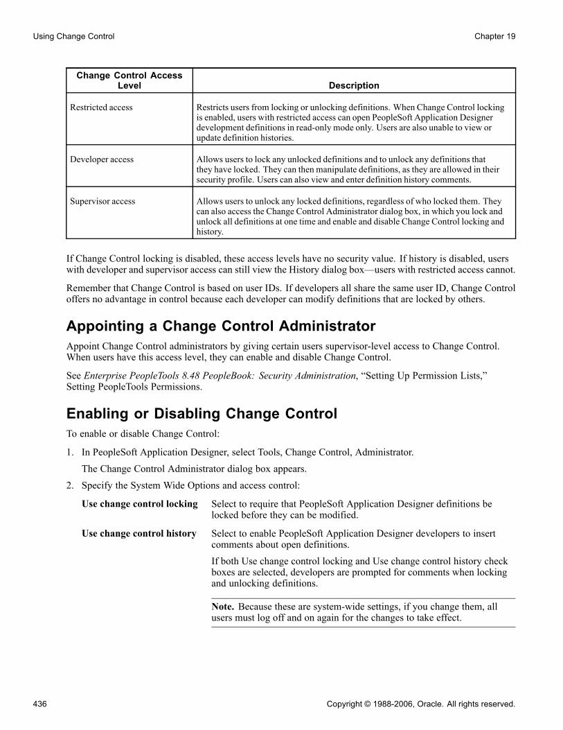
Using Change Control Chapter 19
Change Control AccessLevel Description
Restricted access Restricts users from locking or unlocking definitions. When Change Control lockingis enabled, users with restricted access can open PeopleSoft Application Designerdevelopment definitions in read-only mode only. Users are also unable to view orupdate definition histories.
Developer access Allows users to lock any unlocked definitions and to unlock any definitions thatthey have locked. They can then manipulate definitions, as they are allowed in theirsecurity profile. Users can also view and enter definition history comments.
Supervisor access Allows users to unlock any locked definitions, regardless of who locked them. Theycan also access the Change Control Administrator dialog box, in which you lock andunlock all definitions at one time and enable and disable Change Control locking andhistory.
If Change Control locking is disabled, these access levels have no security value. If history is disabled, userswith developer and supervisor access can still view the History dialog box—users with restricted access cannot.
Remember that Change Control is based on user IDs. If developers all share the same user ID, Change Controloffers no advantage in control because each developer can modify definitions that are locked by others.
Appointing a Change Control AdministratorAppoint Change Control administrators by giving certain users supervisor-level access to Change Control.When users have this access level, they can enable and disable Change Control.
See Enterprise PeopleTools 8.48 PeopleBook: Security Administration, “Setting Up Permission Lists,”Setting PeopleTools Permissions.
Enabling or Disabling Change ControlTo enable or disable Change Control:
1. In PeopleSoft Application Designer, select Tools, Change Control, Administrator.The Change Control Administrator dialog box appears.
2. Specify the System Wide Options and access control:
Use change control locking Select to require that PeopleSoft Application Designer definitions belocked before they can be modified.
Use change control history Select to enable PeopleSoft Application Designer developers to insertcomments about open definitions.If both Use change control locking and Use change control history checkboxes are selected, developers are prompted for comments when lockingand unlocking definitions.
Note. Because these are system-wide settings, if you change them, allusers must log off and on again for the changes to take effect.
436 Copyright © 1988-2006, Oracle. All rights reserved.
Chapter 19 Using Change Control
Lock all definitions Select or clear to lock or unlock all definitions in the database. Usually, youlock all definitions only before a major upgrade, because it permanentlyremoves all individual developer locks.
Using ProjectsThis section provides an overview of projects and discusses how to:
• Use multiple databases for development.• Use distributed development environments.
Understanding ProjectsYou can use all levels of Change Control with or without also using projects. If you decide not to use projects,you rely on the Locked Objects dialog box, rather than the project workspace, to identify locked definitions.The dialog box provides a better overall view of locking status because it shows all of the PeopleSoftApplication Designer definitions in the database, not just those in the current project.
Use projects to track the definitions that are changed as part of a change or feature request. This set ofdefinitions is commonly referred to as the change set. The Options dialog box has an option to insert adefinition into a project when it is modified and saved. If you start with an empty project, this option providesan easy way of tracking the change set for this incident. When the change request is completed, the projectcontains everything that is associated with the change. It’s also a good idea to use the Comments field in theProject Properties dialog box to list any external definitions like COBOL or Structured Query Report (SQR)modules that must be migrated with this change.
Using Multiple Databases for DevelopmentManaging change in a single database environment is straightforward, but very few PeopleSoft users operate ina single database environment. The classic development model uses three databases: development, test, andproduction. You apply all changes to the development database. After you unit-test the change, migrate thechange set to the test database, where it goes through more rigorous testing. Usually, you would run one ormore regression test suites to ensure that you resolve the issue that you intended to resolve with no unwelcomeside effects. Finally, that change set is migrated into the production database. If you find a problem at anystage in the process, the incident is sent back to development and the process begins again.
This model assumes that the development database is the master database. You can use the Change Controllocking feature to lock down the modules on which you and other developers are working. When the changesare completed in the development database, the Change Control administrator is notified and uses the upgradecopy facility to copy the change set into the test environment. As long as you use the technique that isdescribed previously in this section, the project should contain the entire change set. The system tracks all ofthe documentation for the change in the development database. The only information that appears in the testand production databases is a history line indicating it was copied. Definitions move only in one directionin this model: from development to test, then from test to production.
Note. The only case in which you can copy a definition back to development from either test or productionis if a problem must be re-created and another change has already been made to the affected definition. Dothis with extreme care because upgrade copies are destructive and cannot be undone if you discover that youoverlaid another developer’s change. For this reason, you should only apply changes directly to test orproduction databases very rarely.
Copyright © 1988-2006, Oracle. All rights reserved. 437

Using Change Control Chapter 19
Note. This is just one Change Control model that you can use. This is provided to give you an idea of how youcan implement Change Control in your environment. While you do not need to follow this model exactly, it isimportant that you implement a Change Control model that enables you to track changes to the system andprevent developers from overwriting each other’s changes.
Using Distributed Development EnvironmentsIt is good idea to use a master development database, even if each development team works on its owncopy of the database. Developers should lock down the definitions on which they intend to work in themaster development database, then copy those modules to their private databases. This ensures that no otherdeveloper makes a change to those definitions while they are checked out.
When the developer is ready to copy changes back to the master development database, check the ChangeControl history of the locked definitions in the master development database. Do this before using upgradecopy to migrate them back, just in case a Change Control administrator has overridden a lock and madea change while the definitions were checked out.
Note. Change Control administrators should always notify the developer who has a lock on a definition beforethey override to avoid unexpected surprises later.
Using Change ControlThis section discusses how to:
• Lock and unlock definitions.• View locked definitions.• Insert comments.• View Change Control history.• Report Change Control information.
Locking and Unlocking DefinitionsYou can lock and unlock definitions manually. You can also have PeopleSoft Application Designer lockunlocked definitions for you each time that you open them.
You must have developer or supervisor access to Change Control to lock and unlock definitions. If you havesupervisor access, you can also lock all definitions at once. This can be helpful when performing upgradesto ensure that definitions aren’t modified in the middle of the process.
This section discusses how to:
• Lock or unlock an unopened definition in the current project.• Unlock an unopened definition that is not in the current project.• Lock or unlock an open definition.• Lock definitions automatically when you open them.• Lock or unlock all definitions at once.
438 Copyright © 1988-2006, Oracle. All rights reserved.

Chapter 19 Using Change Control
Locking or Unlocking an Unopened Definition in the Current ProjectTo lock or unlock an unopened definition in the current project:
1. In the project workspace, select the Development tab at the base of the workspace window to activatethe development view.
2. Select the definitions that you want to lock or unlock.3. Right-click any of the selected definitions and select Lock Definition or Unlock Definition.
Unlocking an Unopened Definition Not in the Current ProjectTo unlock an unopened definition that is not in the current project:
1. Select Tools, Change Control, View Locked Definitions.The Locked Definitions dialog box appears.
Note. The View Locked Definitions menu item is not available if you have restricted access to ChangeControl.
2. Select the definition type and user.
You can view all locked definitions of the specified type by selecting (all) from the User drop-down list box.
3. Select the definitions to unlock.
4. Right-click any selected definition and select Unlock Definition.
If Change Control history is enabled, you’re prompted for comments.
Locking or Unlocking an Open DefinitionTo lock or unlock an open definition:
1. Activate the definition.
2. Select Tools, Change Control, and then select either Lock Definition or Unlock Definition.
Locking Definitions Automatically When You Open ThemTo lock definitions automatically when you open them:
1. Select Tools, Options, Change Control.
2. Select Lock definition when it is opened.
Now, whenever you open a definition it is locked automatically, unless you have only restricted access toChange Control. In this case, you’re notified that you have restricted access and asked whether you want toopen the definition in read-only mode
Note. Like all settings in the Application Designer Options dialog box, this setting controls the behavioron your workstation only. Also, definitions cannot be unlocked automatically. You must always unlockthem manually.
Locking or Unlocking All Definitions at OnceTo lock or unlock all definitions at once:
1. Select Tools, Change Control, Administrator.
Copyright © 1988-2006, Oracle. All rights reserved. 439

Using Change Control Chapter 19
The Change Control Administrator dialog box appears.2. Select Lock all definitions to lock all definitions, or clear it to unlock all definitions.Locking all definitions applies a database-wide lock that is tagged with your user ID.
Warning! Selecting this check box removes individual locks from all database definitions. You shouldproceed with this step only if you’ve informed all of your developers and given them an opportunity tosave any unsaved work.
3. Click OK.If you’re locking all definitions, you’re warned that this action permanently cancels existing locks. ClickYes.
Viewing Locked DefinitionsAt times you may want to see a definition even if it is locked.
To view locked definitions:
1. Select Tools, Change Control, View Locked Definitions.
The Locked Definitions dialog box appears.
2. Select the user whose locked definitions you want to view.
3. Select the type to display.
You can view only one definition type at a time. You can also unlock definitions in this dialog box.
Inserting CommentsWhen Change Control history is enabled, you can insert comments about an open definition at any time. Tohelp ensure that you insert new comments with each modification, you can instruct PeopleSoft ApplicationDesigner to prompt you for a comment every time you save a definition, every time you lock or unlock adefinition, or both.
This section discusses how to:
• Insert a comment for an unopened definition in the current project.• Insert a comment for an open definition.• Enable a prompt for comments when saving a definition.
Inserting a Comment for an Unopened Definition in the Current ProjectTo insert a comment for an unopened definition in the current project:
1. In the project workspace, select the Development tab at the base of the workspace window to activatethe development view.
2. Select the definition for which you want to insert comments.You cannot insert comments for more than one definition at a time.
3. Right-click the selected definition and select Insert Comment.The Insert Comment dialog box appears.
4. Enter the necessary information:
440 Copyright © 1988-2006, Oracle. All rights reserved.
Chapter 19 Using Change Control
Project Displays the name of the current project by default, but you can delete orreplace this value.
Incident ID Denote the incident to which your development corresponds.
Comments Include information about why and how you’re modifying the definition.If you click OK, the information is inserted into the definition history and the dialog box closes. If youclick Apply, your comments are inserted, but the dialog box remains open. You can then enter commentsfor another history entry. When you click OK or Apply, these new comments are inserted as a newhistory entry; they do not replace the previous entry.
Inserting a Comment for an Open DefinitionTo insert a comment for an open definition:
1. Use the list in the Window menu to navigate to the definition.2. Select Tools, Change Control, Insert Comment.3. Enter the name of the project and incident ID.4. Enter your comments.5. Click OK or Apply.
Enabling a Prompt for Comments When Saving a DefinitionTo be prompted for comments when saving a definition:
1. Select Tools, Options, Change Control.The Change Control page appears.
2. Select Prompt for comments when definition is saved.Whenever you save a definition, the system prompts you to insert history comments.
Note. This setting affects the behavior on your workstation only. One possible drawback to using thissetting is that a definition might be saved many times as part of a single change and you’re promptedfor comments at every save.
Viewing Change Control HistoryFor every PeopleSoft Application Designer development definition in the database, you can view its ChangeControl history.
To view Change Control history:
1. Select Tools, Change Control, View History.The History dialog box appears.
2. Select a definition type and name.The Definition Name list contains only the names of PeopleSoft Application Designer definitions thathave at least one history entry. Click the Refresh button to ensure that you’re viewing the most recentlisting of locked definitions.The history table contains these columns:
Date Displays when each entry was added.
Copyright © 1988-2006, Oracle. All rights reserved. 441

Using Change Control Chapter 19
User Displays who added the entry.
Action Displays why the comment was entered. Five of these Action types—Lock,Informational, Unlock, Rename, and Delete—represent actions thatyou perform in PeopleSoft Application Designer, and for which you’reprompted for comments.
Add Denotes an automatic history entry that PeopleTools inserts when a newdefinition is created. In this case—and whenever the system performs abehind-the-scenes lock or unlock—you aren’t prompted for comments.The Comment column contains the text System Generated.
Note. PeopleSoft Application Designer performs automatic locks andunlocks under certain situations. For example, when you rename a lockeddefinition, that definition must be unlocked before the rename and relockedafterward. Likewise, when you delete a locked definition, the definition isautomatically unlocked after the deletion. The system does not promptyou for comments during any of these unlock or relock actions, butcorresponding history entries are added automatically.
Copy This type of history entry is added automatically when a definition iscopied into the current database. In this case, the Project value is the nameof the copied project in the source database, and no comments are added.
Project, IncidentID,andComment
Displays the project name, incident ID, and relevant comments fromthe Insert Comments dialog box.
3. Double-click a row in the grid to open a history entry, if necessary.
The History Details dialog box appears. This dialog box is a read-only version of the Insert Commentsdialog box. You cannot update the information that is displayed in this dialog box.
Reporting Change Control InformationCurrently, PeopleSoft doesn’t deliver predefined reports for retrieving Change Control information. However,you can create your own reports by querying the Change Control tables.
The two tables that you can use for reporting are the Change Control History table (PSCHGCTLHIST) and theChange Control Locking table (PSCHGCTLLOCK). These tables have an almost identical column structure:
442 Copyright © 1988-2006, Oracle. All rights reserved.

Chapter 19 Using Change Control
Structure of PSCHGCTLHIST
The main difference between these two tables is that PSCHGCTLHIST contains a CHGCTRL_ACTIONfield, while PSCHGCTLLOCK does not.
Each PeopleSoft definition in these tables is uniquely identified by numeric codes (DEFINITIONID columns)and names (DEFINITIONVALUE columns). The different DEFINITIONID and DEFINITIONVALUEcolumn pairs correspond to the various definition key types and values for each kind of definition. You can seethese definition keys when you view the upgrade definition window. For example, translate values have fourkeys—Field Name, Field Value, Language Code, and Effective Date, as in this example:
Viewing definition keys
In the Change Control tables, the row containing the first translate value in the preceding example has thefollowing field values:
DEFINITIONVALUE1 DEFINITIONVALUE2 DEFINITIONVALUE3 DEFINITIONVALUE4
AE_ABEND_ACTION A ENG 1900-01-01
Copyright © 1988-2006, Oracle. All rights reserved. 443
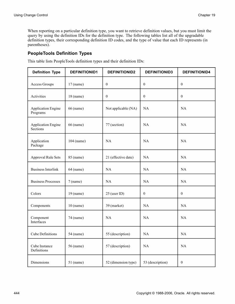
Using Change Control Chapter 19
When reporting on a particular definition type, you want to retrieve definition values, but you must limit thequery by using the definition IDs for the definition type. The following tables list all of the upgradabledefinition types, their corresponding definition ID codes, and the type of value that each ID represents (inparentheses).
PeopleTools Definition TypesThis table lists PeopleTools definition types and their definition IDs:
Definition Type DEFINITIONID1 DEFINITIONID2 DEFINITIONID3 DEFINITIONID4
Access Groups 17 (name) 0 0 0
Activities 18 (name) 0 0 0
Application EnginePrograms
66 (name) Not applicable (NA) NA NA
Application EngineSections
66 (name) 77 (section) NA NA
ApplicationPackage
104 (name) NA NA NA
Approval Rule Sets 85 (name) 21 (effective date) NA NA
Business Interlink 64 (name) NA NA NA
Business Processes 7 (name) NA NA NA
Colors 19 (name) 25 (user ID) 0 0
Components 10 (name) 39 (market) NA NA
ComponentInterfaces
74 (name) NA NA NA
Cube Definitions 54 (name) 55 (description) NA NA
Cube InstanceDefinitions
56 (name) 57 (description) NA NA
Dimensions 51 (name) 52 (dimension type) 53 (description) 0
444 Copyright © 1988-2006, Oracle. All rights reserved.

Chapter 19 Using Change Control
Definition Type DEFINITIONID1 DEFINITIONID2 DEFINITIONID3 DEFINITIONID4
Fields 6 (name) 0 0 0
Field Formats 23 (family name) 0 0 0
File LayoutDefinitions
71 (name) NA NA NA
HTML 90 (name) 95 (type) NA NA
Images 91 (name) 95 (type) NA NA
Indexes 1 (name) 24 (index ID) 0 0
Job Definitions 27 (name) NA NA NA
Menus 3 (name) 0 0 0
Message CatalogEntries
48 (message setnumber)
48 (messagenumber)
16 (language code) 50 (description)
Message Channels 61 (name) NA NA NA
MessageDefinitions
60 (name) NA NA NA
Mobile Page 111 (name) NA NA NA
Message Nodes 62 (name) NA NA NA
Pages 9 (name) NA 0 0
PeopleCode See PeopleCodeDefinition Types
NA NA NA
Problem Type 109 (name) NA NA NA
Process Definitions 29 (process type) 28 (name) 0 0
Process TypeDefinitions
29 (name) 26 (operatingsystem)
20 (database type) NA
Copyright © 1988-2006, Oracle. All rights reserved. 445

Using Change Control Chapter 19
Definition Type DEFINITIONID1 DEFINITIONID2 DEFINITIONID3 DEFINITIONID4
Queries 30 (name) 25 (user ID) 0 0
Records 1 (name) 2 (RecField name) 0 0
RecurrenceDefinitions
31 (name) NA NA NA
Roles 32 (name) 0 0 0
Server Definitions 33 (name) NA NA NA
SQL (StructuredQuery Language)
65 (name) 81 (SQL type) NA NA
Styles 35 (name) 0 0 0
Style Sheets 94 (name) NA NA NA
Translate Values 6 (database fieldname)
22 (value) 21 (effective date) NA
Trees 34 (setID) 68 (user key value) 36 (tree name) 21 (effective date)
Tree Structures 37 (name) 0 0 0
PeopleCode Definition TypesThis table lists PeopleCode definition types and their definition IDs:
Definition Type DEFINITIONID1 DEFINITIONID2 DEFINITIONID3 DEFINITIONID4
Application Engine 66 (PeopleSoftApplication Engineprogram)
77 (section, market,database type,effective date)
78 (step) 12 (method)
ApplicationPackage
104 (applicationpackage)
NA NA NA
ComponentInterface
74 (businesscomponent)
12 (method) NA NA
446 Copyright © 1988-2006, Oracle. All rights reserved.

Chapter 19 Using Change Control
Definition Type DEFINITIONID1 DEFINITIONID2 DEFINITIONID3 DEFINITIONID4
Menu 3 (menu) 4 (bar) 5 (item) 12 (method)
Message 60 (message) 12 (method) NA NA
Page 9 (panel) 16 (language code) 12 (method) NA
Page Field 9 (panel) 16 (language code) 67 (field) 12 (method)
Component 10 (panel group) 39 (market) 12 (method) NA
Component Record 10 (panel group) 39 (market) 1 (record) 12 (method)
Component RecordField
10 (panel group) 39 (market) 1 (record) 2 (fieldname,method)
Record 1 (record) 2 (field) 12 (method) NA
Subscription 60 (message) 87 (subscription) 12 (method) NA
Change Control Supported Definition TypesThese are the supported definition types for change control:
• Activity• Application Engine Program• Approval Rule Set• Business Interlink• Business Process• Component• Component Interface• Field• File Layout• HTML• Image• Menu• Message• Message Channel• Mobile Page
Copyright © 1988-2006, Oracle. All rights reserved. 447
Using Change Control Chapter 19
• Problem Type• Page• Project• Record• SQL• Style Sheet
When reporting on Change Control history, consider one other field: CHGCTRL_ACTION. This field storesthe one-letter code for the various actions that Change Control history tracks:
• A (Add)• C (Copy)• D (Delete)• I (Informational)• L (Lock)• R (Rename)• U (Unlock)
Here’s an example of a SQL query to report on all deleted definitions:
select oprid, definitionvalue1, definitionvalue2,
definitionvalue3, definitionvalue4, dttm_stamp, projectname,
incident_id, descrlong
from pschgctlhist
where chgctrl_action = ’D’
order by oprid, definitionvalue1
Note. Full history tracking is supported only for PeopleSoft Application Designer definitions—businessprocesses, business process maps, fields, menus, panels, panel groups, projects, and records. Other definitiontypes have history entries only when the CHGCTL_ACTION field value is C, and only if they’ve beenupgraded.
448 Copyright © 1988-2006, Oracle. All rights reserved.
PART 4
Performing Updates and Upgrades withPeopleSoft Application Designer
Chapter 20Upgrading with PeopleSoft Application Designer
Chapter 21Comparing Source and Target Definitions
Chapter 22Working with Text Definitions and Text Files During Upgrades
Chapter 23Copying Projects and Definitions


CHAPTER 20
Upgrading with PeopleSoft Application Designer
This chapter provides an overview of a PeopleSoft application upgrade and discusses how to:
• Use the upgrade workspace.• Prepare projects for an upgrade.• View upgrade messages.
Understanding a PeopleSoft UpgradeThis section discusses:
• PeopleSoft Application Designer upgrade features.• Definition types that you can upgrade.
PeopleSoft Application Designer Upgrade FeaturesPeopleSoft Application Designer streamlines the migration of database definitions—such as records, pages,projects, and PeopleCode—from one PeopleSoft database to another. You can perform a complete databaseupgrade or you can upgrade only the definitions included in a particular project. This chapter focuses mainlyon project upgrades, and the PeopleSoft upgrade documentation focuses on complete database upgrades, whichare typically performed when upgrading from one version of a PeopleSoft application to another.
While this chapter does not discuss the specific procedures for an enterprise-wide upgrade for a specificplatform, there are basic steps to perform in PeopleSoft Application Designer regardless of the type ofupgrade, which include:
• Updating your PeopleSoft software.• Identifying the source and target database. The source can be a file, a project, or an entire database.• Comparing the source and target database to determine changed definitions.• Copy any new or changed definitions into your database and adjust all your system components—such asapplication data, SQL tables, indexes, views, and so on—accordingly.
Updating the PeopleSoft software is covered in the installation documentation for Enterprise PeopleToolsand Enterprise applications. This chapter focuses on comparing your source with your target and copying thedefinitions from the source to the target.
When comparing your source and target you can view results in the upgrade workspace, in reports, in yourbrowser, and side-by-side (for pages and text definitions, such as PeopleCode). When copying definitions intothe target database you can use the PeopleSoft Application Designer interface or a command line interface.For text definitions you can use the merge feature.
Copyright © 1988-2006, Oracle. All rights reserved. 451

Upgrading with PeopleSoft Application Designer Chapter 20
Note. The complexity of these tasks performed depends on the type of upgrade you are performing. Forexample, if you are copying brand new definitions from a small project into a source database this is arelatively uncomplicated task, as comparisons are not required and you can immediately begin a copy.However, if you are upgrading an entire database or a large project containing numerous changed definitions itis likely that the compare, merge, or copy process will require more analysis.
Note. To use the PeopleSoft Application Designer upgrade features, you must have full access to projects andupgrade access in the target database. To run a compare you only need read-only upgrade access.
See AlsoEnterprise PeopleTools 8.48 PeopleBook: Security Administration, “Setting Up Permission Lists,” SettingPeopleTools Permissions
The upgrade documentation for your application and platform.
Definition Types That You Can UpgradePeopleSoft Application Designer has the following levels of upgrade support for PeopleSoft definitions:
Upgrade Support Description
Compare and copy This is referred to as "Full support." You can compare thisdefinition between source and target and copy it to thetarget.
Copy to and from file You can copy the definition to the database and to a file.
Copy only You can copy the definition to the target, but you can notcompare definition versions between the source and target.
This table displays the upgrade support for each PeopleSoft definition for which upgrade is available.
Definition Type Compare and CopyCopy to and from
File Copy Only
Access Groups No No Yes
Activities Yes Yes No
Analytic Model Yes Yes No
Application Engine Programs Yes Yes No
Application Engine Sections Yes Yes No
Application Packages Yes Yes No
452 Copyright © 1988-2006, Oracle. All rights reserved.

Chapter 20 Upgrading with PeopleSoft Application Designer
Definition Type Compare and CopyCopy to and from
File Copy Only
Approval Rule Sets Yes Yes No
Archive Objects Yes Yes No
Archive Templates Yes Yes No
Business Interlink Yes Yes No
Business Processes Yes Yes No
Colors Yes Yes No
Component Interfaces Yes Yes No
Components Yes Yes No
Cube Definitions No No Yes
Cube Instance Definitions No No Yes
Dimensions No No Yes
Diagnostic Plug-Ins Yes Yes No
Field Formats Yes Yes No
Fields Yes Yes No
File Layout Definitions Yes Yes No
File References Yes Yes No
File Type Codes Yes Yes No
HTML Yes Yes No
Images Yes Yes No
Copyright © 1988-2006, Oracle. All rights reserved. 453
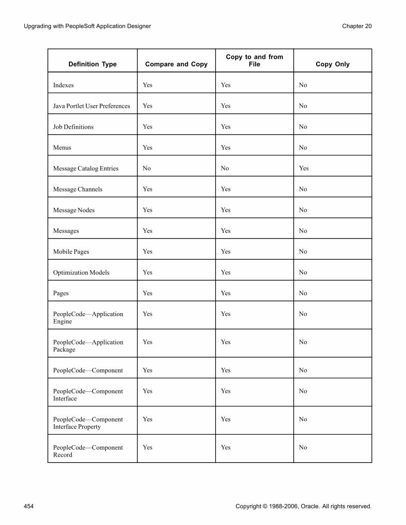
Upgrading with PeopleSoft Application Designer Chapter 20
Definition Type Compare and CopyCopy to and from
File Copy Only
Indexes Yes Yes No
Java Portlet User Preferences Yes Yes No
Job Definitions Yes Yes No
Menus Yes Yes No
Message Catalog Entries No No Yes
Message Channels Yes Yes No
Message Nodes Yes Yes No
Messages Yes Yes No
Mobile Pages Yes Yes No
Optimization Models Yes Yes No
Pages Yes Yes No
PeopleCode—ApplicationEngine
Yes Yes No
PeopleCode—ApplicationPackage
Yes Yes No
PeopleCode—Component Yes Yes No
PeopleCode—ComponentInterface
Yes Yes No
PeopleCode—ComponentInterface Property
Yes Yes No
PeopleCode—ComponentRecord
Yes Yes No
454 Copyright © 1988-2006, Oracle. All rights reserved.

Chapter 20 Upgrading with PeopleSoft Application Designer
Definition Type Compare and CopyCopy to and from
File Copy Only
PeopleCode—ComponentRecord Field
Yes Yes No
PeopleCode—Menu Yes Yes No
PeopleCode—Message Yes Yes No
PeopleCode—Page Yes Yes No
PeopleCode—Page Field Yes Yes No
PeopleCode—Record Yes Yes No
PeopleCode—Subscription Yes Yes No
Permission Lists Yes Yes No
Portal Registry Definition Yes Yes No
Portal Registry Structures Yes Yes No
Portal Registry UserFavorites
Yes Yes No
Portal Registry UserHomepages
Yes Yes No
Problem Types Yes Yes No
Process Definitions Yes Yes No
Process Type Definitions Yes Yes No
Queries Yes Yes No
Records Yes Yes No
Recurrence Definitions Yes Yes No
Copyright © 1988-2006, Oracle. All rights reserved. 455
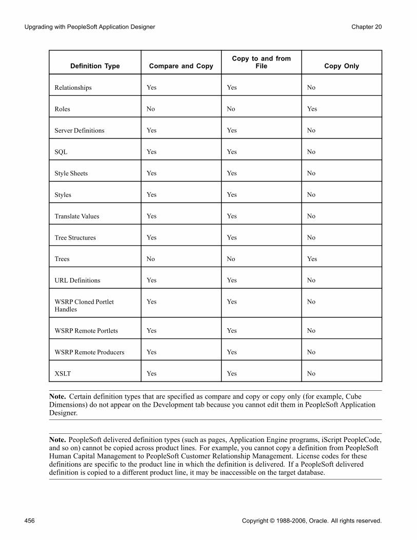
Upgrading with PeopleSoft Application Designer Chapter 20
Definition Type Compare and CopyCopy to and from
File Copy Only
Relationships Yes Yes No
Roles No No Yes
Server Definitions Yes Yes No
SQL Yes Yes No
Style Sheets Yes Yes No
Styles Yes Yes No
Translate Values Yes Yes No
Tree Structures Yes Yes No
Trees No No Yes
URL Definitions Yes Yes No
WSRP Cloned PortletHandles
Yes Yes No
WSRP Remote Portlets Yes Yes No
WSRP Remote Producers Yes Yes No
XSLT Yes Yes No
Note. Certain definition types that are specified as compare and copy or copy only (for example, CubeDimensions) do not appear on the Development tab because you cannot edit them in PeopleSoft ApplicationDesigner.
Note. PeopleSoft delivered definition types (such as pages, Application Engine programs, iScript PeopleCode,and so on) cannot be copied across product lines. For example, you cannot copy a definition from PeopleSoftHuman Capital Management to PeopleSoft Customer Relationship Management. License codes for thesedefinitions are specific to the product line in which the definition is delivered. If a PeopleSoft delivereddefinition is copied to a different product line, it may be inaccessible on the target database.
456 Copyright © 1988-2006, Oracle. All rights reserved.
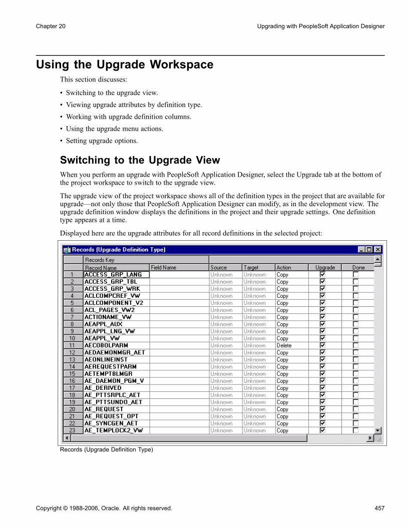
Chapter 20 Upgrading with PeopleSoft Application Designer
Using the Upgrade WorkspaceThis section discusses:
• Switching to the upgrade view.
• Viewing upgrade attributes by definition type.
• Working with upgrade definition columns.
• Using the upgrade menu actions.
• Setting upgrade options.
Switching to the Upgrade ViewWhen you perform an upgrade with PeopleSoft Application Designer, select the Upgrade tab at the bottom ofthe project workspace to switch to the upgrade view.
The upgrade view of the project workspace shows all of the definition types in the project that are available forupgrade—not only those that PeopleSoft Application Designer can modify, as in the development view. Theupgrade definition window displays the definitions in the project and their upgrade settings. One definitiontype appears at a time.
Displayed here are the upgrade attributes for all record definitions in the selected project:
Records (Upgrade Definition Type)
Copyright © 1988-2006, Oracle. All rights reserved. 457

Upgrading with PeopleSoft Application Designer Chapter 20
Viewing Upgrade Attributes by Definition TypeTo view the upgrade attributes by definition type in a project:
1. Open a project.2. Select the Upgrade tab at the bottom of the project workspace.3. Double-click a folder to open the upgrade definition window.With the exception of PeopleCode, the folders in the upgrade view are not expandable. The upgradedefinition window contains a grid with definitions in the project that are of the selected type. For example,if you double-click the Records folder in the upgrade view, the upgrade definition window displays therecords in the project.You can view only one upgrade definition window—and one definition type—at a time. When youdouble-click another definition type in the upgrade view, the upgrade definition window is refreshedwith the new definitions of that type.
Note. You can filter which definitions are displayed in this window. By default, no filtering is applied.
Working with Upgrade Definition ColumnsThe columns in the upgrade definition window display various information about each definition.
Key Displays the name of the definition, plus any other key values. The numberand titles of the key columns vary, depending on the definition type.
Source Displays the definition status in the source (current) database.
Target Displays the definition target database status.
Action Displays the action that is performed if the definition is copied into thetarget database.
Upgrade Select to upgrade the definition during a copy.
Done Is selected when the definition has been copied. You can’t select Done checkboxes yourself—PeopleSoft Application Designer does this after a copy—butyou can clear them. Only definitions that have Upgrade selected and Donecleared are copied during an upgrade.
Execute Only applies to file references and Application Engine definitions. Allowsfile references and Application Engine definitions to be executed whenapplying a change package.
The key columns on the left-hand side of the grid are frozen; they do not scroll horizontally. When you usethe horizontal scroll bar, only the upgrade columns scroll, enabling you to see the key information about thedefinitions at all times. The various definition types have different numbers of key columns. For example,fields have only one column (Field Name), while translates have four (Field Name, Field Value, LanguageCode, and Effective Date).
When viewing definition types with a large nonscrolling region, the horizontal scroll bar is disabled unless atleast one scrolling column is displayed.
To enlarge the window enough so that you can scroll through the upgrade columns:
• Maximize the upgrade definition window.
458 Copyright © 1988-2006, Oracle. All rights reserved.

Chapter 20 Upgrading with PeopleSoft Application Designer
• Maximize PeopleSoft Application Designer.• Hide the project workspace.
To display all of the grid columns at one time when the preceding options don’t enable you to see everycolumn, use the zooming commands in the View menu. With each Zoom Out command, the grid size isreduced. To restore the normal view, select 100%.
You can also resize individual columns by dragging the column border to the appropriate size. If you resize theupgrade columns, save the sizing and use it for every project. Custom key column sizing is not preserved afteryou close a project; these columns reset to their default size.
Using Upgrade Menu ActionsTo access the pop-up upgrade menu, right-click anywhere in the grid in the upgrade definition window.
This table describes the upgrade menu actions and the actions they perform:
Menu Item Action
View Definition Opens multiple definitions in the upgrade grid.
View PeopleCode Opens the PeopleCode Editor. This is enabled forPeopleCode definition types.
Find Definition References Finds all references to the selected definition.
Merge Definition Enables you to compare and merge text definitionsbetween two sources, either a file or another database.Text definitions are PeopleCode, SQL, XSLT, andHTML.
Diff / Merge Page Enables you to compare (side-by-side) page definitionsbetween two sources, either a file or another database,and merge the definitions.
Filtering Opens a cascading menu with filtering options that youcan apply to the upgrade grid. These same options arealso in the View menu.
Refresh View Updates the information in the upgrade definitionwindow.
Set Action Enables you to select and tag definitions for copying anddeleting.
Set Action for Project Enables you to select and tag all definitions in a projectfor copy or delete.
Copyright © 1988-2006, Oracle. All rights reserved. 459

Upgrading with PeopleSoft Application Designer Chapter 20
Menu Item Action
Tag for Upgrade Enables you to tag a group of definitions for upgrade.
Untag for Upgrade Enables you to remove the tag on a group of definitionsfor upgrade.
Reset Done Flag Enables you to reset Done check boxes for a group ofdefinitions.
Reset Project Done Flags Enables you to reset all Done check boxes.
Insert Definitions into Project Opens the Insert Definitions into Project dialog box.
Remove from Project Removes the selected definitions from the currentproject. You can also use the DELETE key.
Project Properties Opens the Project Properties dialog box, in which youdefine properties for the project, like description.
Setting Upgrade OptionsThis section discusses how to:
• Access the upgrade options.• Set general options.• Set compare options.• Set report options.• Set report filter options.• Set copy options.
Accessing the Upgrade OptionsTo access the upgrade options:
1. Select Tools, Compare and Report.
2. Sign in to an upgrade target database.
3. On the Compare and Report dialog box, click Options, and select the appropriate upgrade option tab.
Preserving Project Item StatusAccess the Compare and Report dialog box and view the Project Item Status/Child Definitions group box.
Setting General OptionsAccess the Upgrade Options dialog box and select the General Options tab.
460 Copyright © 1988-2006, Oracle. All rights reserved.

Chapter 20 Upgrading with PeopleSoft Application Designer
Upgrade Options dialog box: General Options tab
Use the Upgrade Options dialog box to set general options for the Compare or Copy process.
Commit Limit Set the commit limit.Start with the default of 50. If the Copy process seems slow and there issufficient log file space, try increasing the commit limit. You can modify theinitial project default commit limit on the PeopleTools Options page.Very large commit limits, however, can cause more work if something goeswrong during the copy. For example, if the commit limit is set to 1,000 and theCopy process stalls on the 999th definition, none of the previous definitionsare copied. The Copy process must be performed again.
Audit Flags on Records Select one:
• Keep Target Audit Flags: Select to preserve all of the enabled target flags.This is the default. Audit flags that are enabled in the source are alsoretained. Differences between the source and target audit flags are notshown on the compare report.
• Set Target Audit Flags from Source: Select to copy audit flag settings fromthe source to the target database.
Copyright © 1988-2006, Oracle. All rights reserved. 461

Upgrading with PeopleSoft Application Designer Chapter 20
DDL on Records andIndexes
Select one:
• Keep Target DDL: Select to preserve the target DDLs. This is the default.Differences between the source and target DDL are not shown on thecompare report.
• Take DDL from Source: Select to copy the DDL from the source to thetarget database.
Portal StructuresPermission List
Select one:
• Keep Target References: Select to preserve the target portal structurespermission list references. This is the default.
• Set References from Source: Select to copy the portal structures permissionlist references from the source to the target database.
Chartfield Options Set the Display Size Page Property:
• Keep Target Display Size: Does not copy any display changes to aChartField on the source database (the target values are saved). If this isset for a Compare process, no differences between the source and target inthe named fields are displayed. If the only differences on the page are theChartField display properties, then the page compares as the same for both.
• Set Display Size from Source: Copies the position, as well as the size andtype attributes, from the source to the target database.
Set the Database Field Format:
• Keep Target Field Format: Does not copy any changes to the field formatvalues for a database field that is a ChartField on the source database, andpreserves the target field format values. If this is set for a Compare process,any changes to the ChartField field format attributes are not displayed. Ifthese attributes are the only changes for a field, then the definition comparesas the same for both.
• Set Field Format from Source: Copies the ChartField field format attributesfrom the source to the target database.
Setting Compare OptionsAccess the Upgrade Options dialog box and select the Compare Options tab.
462 Copyright © 1988-2006, Oracle. All rights reserved.
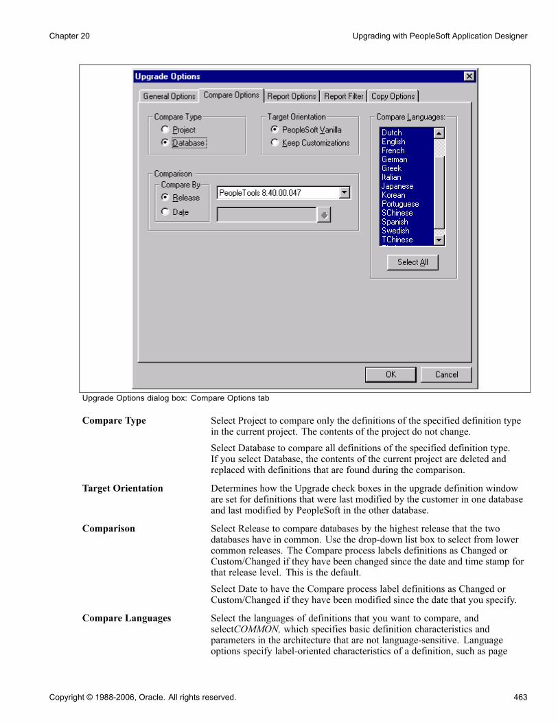
Chapter 20 Upgrading with PeopleSoft Application Designer
Upgrade Options dialog box: Compare Options tab
Compare Type Select Project to compare only the definitions of the specified definition typein the current project. The contents of the project do not change.Select Database to compare all definitions of the specified definition type.If you select Database, the contents of the current project are deleted andreplaced with definitions that are found during the comparison.
Target Orientation Determines how the Upgrade check boxes in the upgrade definition windoware set for definitions that were last modified by the customer in one databaseand last modified by PeopleSoft in the other database.
Comparison Select Release to compare databases by the highest release that the twodatabases have in common. Use the drop-down list box to select from lowercommon releases. The Compare process labels definitions as Changed orCustom/Changed if they have been changed since the date and time stamp forthat release level. This is the default.Select Date to have the Compare process label definitions as Changed orCustom/Changed if they have been modified since the date that you specify.
Compare Languages Select the languages of definitions that you want to compare, andselectCOMMON, which specifies basic definition characteristics andparameters in the architecture that are not language-sensitive. Languageoptions specify label-oriented characteristics of a definition, such as page
Copyright © 1988-2006, Oracle. All rights reserved. 463

Upgrading with PeopleSoft Application Designer Chapter 20
names, labels, and messages. If you do not select COMMON, basic definitioncharacteristics are omitted.If you need specific languages and basic definition characteristics, also selectCOMMON. However, to copy only language attributes of a definition, youdo not need COMMON.Clicking Select All is the recommended default. Make sure that the languagesin the source and target databases match. Press the CTRL key and your mouseto clear unwanted languages.
Setting Report OptionsAccess the Upgrade Options dialog box and select the Report Options tab.
Upgrade Options dialog box: Report Options tab
Report Output • Directory: Displays the compare report output directory. To change theoutput directory path, select Tools, Options from the PeopleSoft ApplicationDesigner toolbar, and select the General tab.
• Font and Size: Displays the font type and size that will appear in the comparereport output. Click Font to select a different font or to change the font size.
• Generate Browser Reports: Select to generate HTML reports that you canview in a browser in addition to the reports that appear in the ApplicationDesigner workspace.
464 Copyright © 1988-2006, Oracle. All rights reserved.
Chapter 20 Upgrading with PeopleSoft Application Designer
See Chapter 21, “Comparing Source and Target Definitions,” Workingwith Browser Reports, page 479.
• Generate Composite Reports: Select to generate a composite report, which isa subset of information showing only the definitions customized at your sitethat were also modified in the most recent PeopleSoft release.- Old Release Report Output Directory: Enter the directory containingthe compare reports run on the database for your previous PeopleSoftinstallation: the database from which you are upgrading.
- Old Release Source Database Name: Enter the source database name youspecified when running the compare reports on your previous PeopleSoftinstallation. This enables the system to identify the appropriate databasedefinitions listed within the compare reports.
See Chapter 21, “Comparing Source and Target Definitions,” Workingwith Composite Reports, page 483.
PeopleCode Report Specify the PeopleCode report options.For PeopleCode compare reports, specify whether to show the entire programon the report (the default setting) or only the code differences between thesource and target. If you select the latter, you can specify the number ofcode lines to show above and below the difference for context. The valuesfor the number of lines to show are 0 to 99. A value of 0 shows only thedifference line. A value greater than 0 shows that many lines above andbelow the difference line.
Note. The PeopleCode report options are global across all projects. Changingsettings for one project changes all subsequent PeopleCode compares,regardless of project.
Report Data Color Select the report data color.Use the Browse button to display the standard color dialog box. Choose acolor that is not included in the drop-down list box or create a custom color.
• Additions: Select a color for additional data values on the source database.These are also source-only values. The default value is dark green.
• Deletions: Select a color for data values that are deleted from the sourcedatabase. These are target-only values. The default value is red.
• Differences: Select a color for changed values, which are both source andtarget values. The default value is blue.
Setting Report Filter OptionsAccess the Upgrade Options dialog box and select the Report Filter tab.
Copyright © 1988-2006, Oracle. All rights reserved. 465

Upgrading with PeopleSoft Application Designer Chapter 20
Upgrade Options dialog box: Report Filter tab
When you perform a comparison, the system generates a report for each definition type compared. Thesereports provide detailed information about how each definition in the source differs from its counterpart inthe target.
Before performing a comparison, you can select the definition status combinations with which you generatereports by using report filter options. For example, during an upgrade to a new PeopleSoft release, youmight decide that if a definition that was last changed in the target by PeopleSoft is found in the source andit hasn’t changed since the last upgrade, you don’t need to see information about the definition differences(because you intend to accept the new PeopleSoft version). In this case, you want to filter the comparereports so that a report is not generated if:
• The source is any status.• The target is unchanged.
Note. Filtering comparison reports does not affect which definitions are added to a project during a databasecomparison, only which definitions are reported. Definitions that are defined differently in the two databasesare always added to the project.
Select the check boxes corresponding to the definition status combinations that you want to report.
Each row in the matrix corresponds to the definition status in the source database. Each column corresponds tothe definition status in the target.
466 Copyright © 1988-2006, Oracle. All rights reserved.

Chapter 20 Upgrading with PeopleSoft Application Designer
The default settings for report filtering show conflicting configured definitions only.
• To reset your selections to the default setting, click the Default button.
• To select all definition status combinations, click the Select All button.
• If you don’t want to generate any reports, click the Deselect All button to clear all of the check boxes.
Setting Copy OptionsAccess the Upgrade Options dialog box and select the Copy Options dialog box.
Upgrade Options dialog box: Copy Options tab
Copy Languages Select a specific language and COMMON, which specifies basicdefinition characteristics and parameters in the architecture that are notlanguage-sensitive. Language options specify label-oriented characteristics ofa definition, such as page names, labels, and messages. If you do not selectCOMMON, basic definition characteristics are omitted. If you need specificlanguages and basic definition characteristics, also select COMMON.Click Select All is the recommended default. Make sure that the languagesin the source and target databases match. Otherwise, you might overwritetranslations in the target. Use the CTRL key and your mouse to clear unwantedlanguages.
Copyright © 1988-2006, Oracle. All rights reserved. 467
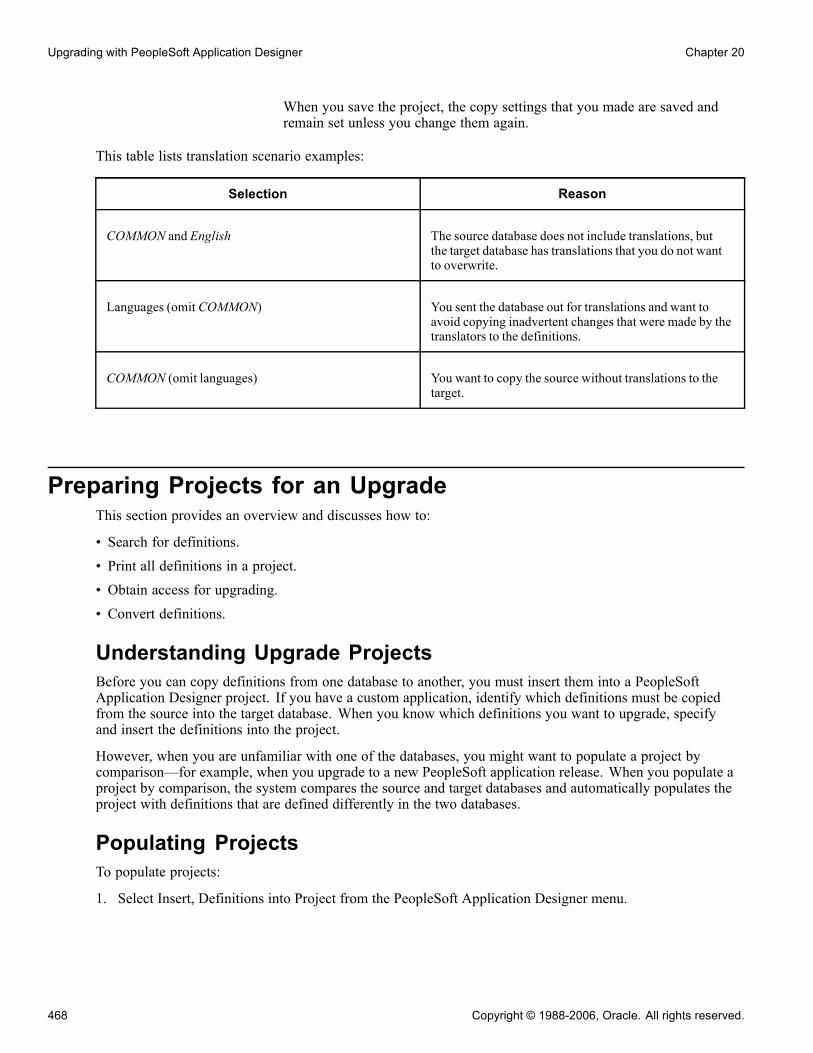
Upgrading with PeopleSoft Application Designer Chapter 20
When you save the project, the copy settings that you made are saved andremain set unless you change them again.
This table lists translation scenario examples:
Selection Reason
COMMON and English The source database does not include translations, butthe target database has translations that you do not wantto overwrite.
Languages (omit COMMON) You sent the database out for translations and want toavoid copying inadvertent changes that were made by thetranslators to the definitions.
COMMON (omit languages) You want to copy the source without translations to thetarget.
Preparing Projects for an UpgradeThis section provides an overview and discusses how to:
• Search for definitions.• Print all definitions in a project.• Obtain access for upgrading.• Convert definitions.
Understanding Upgrade ProjectsBefore you can copy definitions from one database to another, you must insert them into a PeopleSoftApplication Designer project. If you have a custom application, identify which definitions must be copiedfrom the source into the target database. When you know which definitions you want to upgrade, specifyand insert the definitions into the project.
However, when you are unfamiliar with one of the databases, you might want to populate a project bycomparison—for example, when you upgrade to a new PeopleSoft application release. When you populate aproject by comparison, the system compares the source and target databases and automatically populates theproject with definitions that are defined differently in the two databases.
Populating ProjectsTo populate projects:
1. Select Insert, Definitions into Project from the PeopleSoft Application Designer menu.
468 Copyright © 1988-2006, Oracle. All rights reserved.
Chapter 20 Upgrading with PeopleSoft Application Designer
PeopleSoft Application Designer designates certain definition types as related to a parent or controllingdefinition type. For example, a record’s related definitions can include fields, indexes, and subrecords.When you insert definitions into a project for upgrading, it can be important for these related definitionsto be included.
2. Select the definitions and click Insert.3. Select Tools, Options.4. On the Project tab, review the settings in Related Definitions Options and reset.
Searching for DefinitionsTo find a definition in the project select Edit, Find from the menu. This opens the Find dialog box where youcan perform a search for a text string in an upgrade definition window.
Printing All Definitions in a ProjectYou can print a project definition for all of the definition types in the current project. This differs fromthe Print menu item, which prints only the currently selected definition type that is open in the upgradegrid. The data, however, is the same.
To print a project definition for all definitions in current project, select File, Print Project from the PeopleSoftApplication Designer toolbar.
Obtaining Access for UpgradingTo use the PeopleSoft Application Designer upgrade features, you must have full access to projects andupgrade access in the target database.
Also, lock all PeopleSoft Application Designer definitions in the source and target databases before comparingand copying projects. To do this, you need supervisor-level access to Change Control (in the Tools menu). Ifyour Change Control administrator performs this action for you, the administrator’s user ID is the only one thatis allowed to perform the copy while the target definitions are locked.
Viewing Upgrade MessagesThis section discusses how to:
• Determine whether errors were encountered.• View messages.• Print upgrade messages.• Clear messages.
Understanding Upgrade MessagesDuring the compare and copy processes discussed in this section, if the system encounters any errors youwill be notified through system messages. These messages alert you to various areas that may need to becorrected for a successful upgrade compare and copy.
Copyright © 1988-2006, Oracle. All rights reserved. 469

Upgrading with PeopleSoft Application Designer Chapter 20
Determining Whether Errors Were EncounteredSelect the Upgrade tab in the output window to determine whether any errors were encountered duringthe Compare or Copy process.
Upgrade view in the output window
This view displays upgrade messages pertaining to the definition type that was most recently displayed in theupgrade definition window. In the preceding example, Access Groups was the last definition type that wasviewed in the window.
Viewing MessagesTo view messages:
1. Open the project.2. Select the Upgrade tab in the project workspace.3. Double-click the folder of the definition type for which you want to view messages, or click the projecticon to view all messages.Any upgrade messages for that definition type appear in the output window.
Printing Upgrade MessagesTo print upgrade messages:
1. View the messages that you want to print.2. Right-click the output window and select Print.
Clearing MessagesTo clear messages:
1. View the messages that you want to clear.2. Right-click the output window and select Clear.
470 Copyright © 1988-2006, Oracle. All rights reserved.

CHAPTER 21
Comparing Source and Target Definitions
This chapter includes an overview and discusses how to:
• Work with compare reports.• Work with workspace reports.• Work with browser reports.• Work with composite reports.• Work with definition status.• Compare and merge page definitions.• Compare definitions for upgrade using the command line.
Understanding the Compare ProcessPeopleSoft Application Designer enables you to compare the contents of the database to which you are signedon (or project within) with the target database or an exported project file. It enables you to view the status ofeach definition in each location so you can then decide which definitions to keep.
There are two ways to compare definitions:
• Compare all database definitions of a certain type, such as record definitions. After doing so, you populatethe upgrade project with only the definitions that are defined differently in the source than in the target.
• Compare only the definitions in the current upgrade project to the equivalent definitions in the targetdatabase or file.
When performing comparisons between source and target definitions, PeopleSoft Application Designerenables you to:
• Generate workspace reports.These reports appear in the PeopleSoft Application Designer workspace immediately after the compareprocess completes.
• Generate browser reports.These reports are written to HTML and XML files enabling you to open the report in a browser, share thereport with coworkers easily, and store report data in an industry-standard format.
• Visually compare page definitions.This feature enables you to view the source and target page definitions side-by-side with differencesclearly marked.
• Visually compare and merge text definitions.
Copyright © 1988-2006, Oracle. All rights reserved. 471
Comparing Source and Target Definitions Chapter 21
This feature enables you to view the source and target PeopleCode, HTML, SQL, XSLT definitionsside-by-side with differences clearly marked. It also enables you to merge source PeopleCode with targetPeopleCode.
Comparing All Definitions by TypePeopleSoft Application Designer performs comparisons on one definition type at a time. For each definitiontype that you select, the system removes any existing definitions of that type from the current project andrepopulates the project based on the comparison results. For this reason, be careful when performing adatabase comparison on a predefined project.
For example, suppose that your project includes several record, page, and menu definitions and you performa database comparison on pages only. All of the page definitions that were originally in the project areremoved and replaced by any page definitions that were found in the Compare process. However, the recordand menu definitions in the project are not affected.
Performing a database comparison overwrites custom upgrade settings with the defaults for the specifiedtarget orientation.
Comparing Definitions by ProjectIf you manually inserted definitions into the project and you want to see how those definitions differ fromthe same definitions in another database, perform a project comparison. This method compares only thedefinitions in the project and does not repopulate the project—except in record and field comparisons. Upgradesettings are never modified when you perform a project comparison.
When records are compared—during a database or project comparison—differences that are found in recordfields are written into the project. For example, suppose that Record A in the source database containsrecord fields 1, 2, 3, 4, and 5, and Record A in the target database contains fields 2, 4, 6, and 7. Before thecomparison, the project contains only Record A. After the comparison, the project contains Record A andrecord fields 1, 3, 5, 6, and 7.
Similarly, when field definitions are compared, differences that are found in the field labels are inserted intothe project as new field definitions. For example, suppose that you are comparing the source with the target,and both databases have the same field definitions. However, the field label for one of those field definitionsis different. The source field definition is labeled Employee ID, but in the target, it is labeled Staff ID. TheCompare process creates a new field definition that is labeled Staff ID. After the comparison, the projectcontains both an Employee ID field and a Staff ID field.
Note. These are the only situations where a project comparison repopulates a project.
Synchronizing Databases When Comparing Record DefinitionsThe Upgrade Copy process synchronizes databases when performing an upgrade compare and copy forrecord definitions. During the upgrade copy (CopyProp only) of a table, subrecord, or temporary table, thesystem reorders the indexes (_, 0 through 9) to follow the source index order. The target order matchesthe source order after the copy.
For example, suppose that the source record, Z, is a table with fields B, A, C, G, H and the target record, Z, is atable with fields A, B, F, G, C, H where all of these conditions are true:
• F is a customization and a Key field.
• A and B are exactly the same except for field order, and both are keys.
• C, G, H are exactly the same except for field order, and they are nonkey fields.
472 Copyright © 1988-2006, Oracle. All rights reserved.

Chapter 21 Comparing Source and Target Definitions
In this example, the upgrade compare produces project items for this record:
recname fieldname src status tgt status upgradeaction
take action
Z Not applicable(NA)
Chg UnChg copyprop Y
Z F Abs *Chg delete N
* Unless the F record field is deleted, an upgrade copy and compare always shows this project item.
The result of an upgrade copy on this record changes record fields A, B, F, G, C, and H in the target databaseto B, F, A, G, C, and H, without moving the nonkey fields. Another upgrade compare would producethe same project items.
Likewise, during an upgrade copy of a view or dynamic view, the target order is reordered to match the sourcewhen a record field project item is copied and the source order does not match the target order.
For example, suppose that the source record, Z, is a view with fields B, A, C, and the target record, Z, is a viewwith fields A, B, F, C where all of these conditions are true:
• F is a customization.• A and B are exactly the same except for field order.
In this example, the upgrade compare produces project items for these record fields:
recname fieldname src status tgt status upgradeaction
take action
Z A Chg UnChg Copy Y
Z B Chg UnChg Copy Y
Z C -- -- Copy Y
Z F Abs *Chg Delete N
* Unless record field F is deleted, an upgrade copy and compare always shows this project item.
The result of an upgrade copy changes A, B, F, C in the target database to B, F, A, C.
Another project compare would produce these project items:
Copyright © 1988-2006, Oracle. All rights reserved. 473
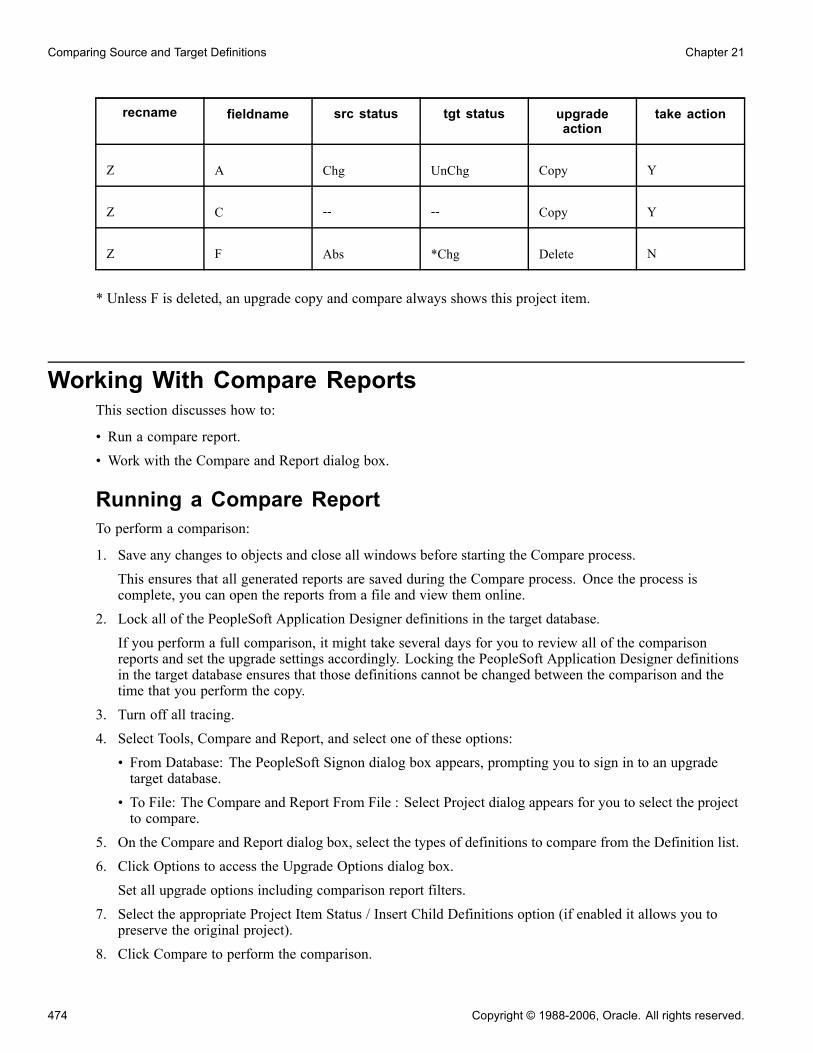
Comparing Source and Target Definitions Chapter 21
recname fieldname src status tgt status upgradeaction
take action
Z A Chg UnChg Copy Y
Z C -- -- Copy Y
Z F Abs *Chg Delete N
* Unless F is deleted, an upgrade copy and compare always shows this project item.
Working With Compare ReportsThis section discusses how to:
• Run a compare report.• Work with the Compare and Report dialog box.
Running a Compare ReportTo perform a comparison:
1. Save any changes to objects and close all windows before starting the Compare process.
This ensures that all generated reports are saved during the Compare process. Once the process iscomplete, you can open the reports from a file and view them online.
2. Lock all of the PeopleSoft Application Designer definitions in the target database.
If you perform a full comparison, it might take several days for you to review all of the comparisonreports and set the upgrade settings accordingly. Locking the PeopleSoft Application Designer definitionsin the target database ensures that those definitions cannot be changed between the comparison and thetime that you perform the copy.
3. Turn off all tracing.
4. Select Tools, Compare and Report, and select one of these options:
• From Database: The PeopleSoft Signon dialog box appears, prompting you to sign in to an upgradetarget database.
• To File: The Compare and Report From File : Select Project dialog appears for you to select the projectto compare.
5. On the Compare and Report dialog box, select the types of definitions to compare from the Definition list.
6. Click Options to access the Upgrade Options dialog box.
Set all upgrade options including comparison report filters.
7. Select the appropriate Project Item Status / Insert Child Definitions option (if enabled it allows you topreserve the original project).
8. Click Compare to perform the comparison.
474 Copyright © 1988-2006, Oracle. All rights reserved.

Chapter 21 Comparing Source and Target Definitions
The system creates online reports for the definitions that you are comparing. Upgrade Compare reports aresaved to the location you specify in the Report Output Directory field in Tools, Options on the General tab.
Note. You can also compare definitions using command line syntax.
Working with the Compare and Report Dialog BoxAccess the Compare and Report dialog box.
Compare and Report dialog box
Note. Depending on whether you are comparing to a database or from a file, the dialog box name changesaccordingly.
Source Identifies the file or database name, the application release, and the servicepack level of the source file or database.
Target Identifies the database name, the application release, and the service packlevel of the target database.
Update Item Status/ChildDefinitions
Deselect the Update Project Item and Child Definitions option to preservethe status of the items in your upgrade project and the child definitions whenrunning a compare. Child definitions apply only to records and fields inwhich fields are the child definitions of the record, and field labels are thechild definitions of record fields.When running a compare report, the system compares the definitions in ananother database or file to the database to which you are currently signed on.Based on the compare results, the system updates the status of the projectitems in your upgrade project in the definition window. For example, afterrunning the compare, the system inserts the status of the Source and Target(Absent, Changed, Unchanged, and so on), the Action to take (None, Copy,CopyProp, and so on).
Copyright © 1988-2006, Oracle. All rights reserved. 475
Comparing Source and Target Definitions Chapter 21
Regarding child definitions with the case of records, if a record is the sameversion in both places, the system removes the fields. With the case of fields,if a field is the same version in both places the system removes the field labelsfrom the upgrade project definition.When a child item is found to be different between the two places, then thatitem is inserted into the project so the child item can then be copied as aunique item. When this option is deselected, no child items are deleted norinserted into the project.In some cases, as in when you want to compare the same upgrade project tomultiple sources, for example a demo database, a production database, and aproject file, you may decide to deselect this option so that the source upgradeproject remains unchanged. When deselected, the project item status and childdefinitions information only appears in the generated compare report, notonline in the PeopleSoft Application Designer project definition.
Note. By default, this setting is selected, which should accommodate mostsituations.
Note. This option applies only when performing project compares, and isnot applicable when performing a full database compare (Compare Type isset to Database on the Compare Options tab in the Upgrade Options dialogbox). A full database compare should start with an empty upgrade project andinsert the different items into the upgrade project.
Note. When performing a compare from file, if the option is turned off,the resulting project definition after the compare will have the same statussettings and project items as in the file project definition. The comparereports will still reflect the status settings and differences in any child items.When the option is left on, the compare will change the project definitionbased on the compare results, changing the status settings, and insertingor deleting child items as needed.
Definition Displays the current set of definitions being compared. The system onlycompares the definitions in the list that are highlighted.
Compare Executes the compare process.
Cancel Cancels the compare process.
Options Opens the Upgrade Options dialog box.
See Chapter 20, “Upgrading with PeopleSoft Application Designer,” SettingUpgrade Options, page 460.
Select All/Deselect All Selects all the definitions in the Definition list, or deselects all.
476 Copyright © 1988-2006, Oracle. All rights reserved.

Chapter 21 Comparing Source and Target Definitions
Working With Workspace ReportsPeopleSoft provides online comparison reports in PeopleSoft Application Designer. These reports appear inthe project workspace area after you run a compare report.
This section discusses how to:
• Access reports.• Search for definitions in reports.• Print the report.• Save reports as text files.
Accessing ReportsTo access reports:
1. Select Tools, Compare and Report from the PeopleSoft Application Designer toolbar.2. Sign in to the target database.The system automatically displays a comparison report for each definition that you selected to be copied.If the current definition type has a PeopleSoft Application Designer based editor, you can double-clickthe definition name in the report to open it. If the comparison report is large, you can search for specificdefinition names.
Searching for Definitions in ReportsFor long compare reports, it is useful to perform a search to locate specific items. The Find in Report featuresearches by column. To search for an object in a comparison report highlight or place your cursor in thecolumn that you want to search and select Edit, Find in Report.
Printing the ReportThis section provides an overview of a report and discusses how to:
• Print the comparison report.
• Print a comparison report from a file.
• Move print files.
Printing the Comparison ReportThis is a print preview of the comparison report:
Copyright © 1988-2006, Oracle. All rights reserved. 477

Comparing Source and Target Definitions Chapter 21
Print preview comparison report
To print the comparison report select File, Print. The standard Print dialog box appears, enabling you to selectthe printer, number of copies, and so on.
Printing a Comparison Report From a FileTo print a comparison report from a file:
1. To print a saved comparison report, select File, Report from File.2. Select Print Preview, Print, or View Report.These options require that you specify the report name and its location in a standard Open dialog box.View Reportdisplays the specified report in the project workspace.
Moving Print FilesYou might want to move the comparison report files to another directory or send them as email attachments.Each comparison report file is saved as two files with the following format:
• Upg<number>DefinitionType.prt• Upg<number>DefinitionType.idx
Both files (filename.prt and filename.idx) are required to view or print the report.
478 Copyright © 1988-2006, Oracle. All rights reserved.
Chapter 21 Comparing Source and Target Definitions
Saving Reports as Text FilesWhile the report is open in the workspace, you can save the workspace report as a text file. This enables you toimport the report results into applications of your choice, such as Microsoft Excel.
To save the workspace report as a text file:
1. Select File, Save Report As.2. On the Save Report As dialog box insert a file name into the File Name edit box, and select a file typefrom the Save as type drop-down list.You can select Tab Delimited (.txt) or Comma Delimited (.csv).
3. Click Save.
Working with Browser ReportsThis section provides an overview and discuses how to:
• Access and share browser reports.
• Select a project.
• Search for definitions.
• View report details.
• View status summary.
• View compare results by definition type.
Understanding Browser ReportsBrowser reports enable you to view compare results using your browser.
You use the Compare Report Viewer to view and navigate within the results. The Compare Report Viewer is aclient-based HTML program through which you view the compare results, which are stored in XML. Havingthe compare results in HTML and XML enables you to:
• Share compare results online with colleagues that do not have Enterprise PeopleTools installed.• Display results in custom formats using the data stored in the generated XML files.
By setting the Generate Browser Reports option, when you run the Compare and Report process, the systemgenerates browser reports in addition to the workspace reports that automatically appear in the PeopleSoftApplication Designer workspace.
Accessing and Sharing Browser ReportsThis section discusses how to:
• Access browser reports.• Share browser reports.
Copyright © 1988-2006, Oracle. All rights reserved. 479

Comparing Source and Target Definitions Chapter 21
Accessing Browser ReportsTo access a browser report double-click on the line in the output window containing "Browser CompareReport Created.”
PeopleSoft Compare Report Viewer
The Viewer menu contains menu options related to navigating within the report. The Definition Types menuenables you to dill down into the compare data for each definition type compared. The Definition Types menuonly contains the definitions compared.
Sharing Browser ReportsPeopleSoft Application Designer writes the browser reports to a subdirectory named after the project namewithin the Report Output Directory specified on the General tab on the Options dialog. For example, if theReport Output Directory is c:\psreports and the project name is “PROJECT,” then the browser reports exist inc:\psreports\PROJECT. To view the compare results, double-click CompareViewer.html and then select thedesired project name.
For each type of definition you compare, there is a subdirectory containing XML files storing the comparedata for that definition type. For example, if you compared pages, the XML file containing compare data forthe page compare exists in c:\psreports\PROJECT\Pages. These files can be used as source data for customdisplays of the compare data. The PeopleSoft Compare Report Viewer uses these XML files along with variousHTML and XSL files to present your compare data.
To share the browser reports, PeopleSoft recommends:
• Copying the entire high-level report output directory (containing all subdirectories, HTML, and XSL files)and copying it to a shared network drive.
• Compressing the entire directory and sending or posting individual copies as needed.
480 Copyright © 1988-2006, Oracle. All rights reserved.

Chapter 21 Comparing Source and Target Definitions
Selecting a ProjectIf you’ve run multiple compare reports on the same workstation, the PeopleSoft Compare Report Viewerenables you to switch between them easily.
To select a project:
1. Click Select Project.2. Select the appropriate project in the Project Name list.
Searching for DefinitionsYou can search for specific definitions within the compare data.
To search for definitions:
1. Select Search.2. From the Definition Type list, specify the appropriate definition type, such as Records.3. In the Search Text edit box, enter the name or part the name of the definition you want to view.
Note. You must enter at least three characters.
Note. The search returns the parent and child definitions. For example, if you enter ’RecordA’ thatcontains FieldB and Field C, the search returns RecordA, RecordA.FieldB, and RecordA.FieldC. Also, thesearch returns all definitions beginning with the search string entered.
4. Click Search.
Viewing Report DetailsClick Report Details to view information related to the databases and/or files compared.
Project Name The name of the project in the primary database.
PeopleTools Release The PeopleTools release number on which the primary database runs.
Source Database/SourceFile
The name of the primary database or file depending on which compareoption you selected.
Source Date The date the primary database was last updated.
Target Database The name of the secondary database.
Target Date The date the secondary database was last updated.
Compare By Displays the Comparison options selected on the Compare Options dialog boxeither the release or date.
See Chapter 20, “Upgrading with PeopleSoft Application Designer,” SettingUpgrade Options, page 460.
Viewing Status SummaryTo view the status summary, click Status Summary.
Copyright © 1988-2006, Oracle. All rights reserved. 481
Comparing Source and Target Definitions Chapter 21
The status summary is a high-level view of the compare results showing the definitions compared and theoccurrence of differences. The summary table indicates whether the difference occurred because of additions,modifications, or deletions that were the result of activity at your site, or whether the difference occurred asa result of an addition or modification made by PeopleSoft. This summary can be useful for managers andexecutives who are scoping and budgeting for an upgrade.
Each of the columns in the status summary indicate the number of items found to differ by definition type.The columns represent the "Source" and "Target" status values set during the compare process. You can clickon any of the cell values to view the items filtered for each particular status result. You can also click thevalue in the Definition Type column to view further status information.
The following table shows how each column in the status summary table equates to the status in the source andtarget locations.
Customer Added Source: AbsentTarget: *Changed or *Unchanged
Customer Modified Source: Changed or Unchanged
Target: *Changed or *Unchanged
Customer Deleted Source: AbsentTarget: Changed or Unchanged
PeopleSoft Added Source: AnyTarget: Absent
PeopleSoft Modified Source: Changed or UnchangedTarget: Changed or Unchanged
Note. If you have generated composite reports, two tabs appear for the status summary: Compare Reportand Composite Report.
Note. The compare report values reflect the assumption that the source is the delivered PeopleSoftdemonstration database and the target is a customer’s production copy of a database.
See AlsoChapter 21, “Comparing Source and Target Definitions,” Working with Definition Status, page 487
Viewing Compare Results by Definition TypeThe Definition Types menu displays a menu item for each type of definition you compared. Click the link for aparticular definition type to view the comparison results for each definition of that type.
Each definition compared appears in a grid containing identification information relevant to that definitiontype as well as the status of the definition in each location, the action, and the upgrade flag. The identificationcolumns are links enabling you to drill down into the compare results of that definition so you can comparesource and target values.
Expand All Expands all definitions in the grid to reveal all associated attributes andchild definitions.
482 Copyright © 1988-2006, Oracle. All rights reserved.

Chapter 21 Comparing Source and Target Definitions
Collapse All Collapses the expanded grid so that only the list of definitions appear.
Show All Attributes Click to show all attributes within a definition in Expand All mode after hidingan attribute or hiding all attributes.
Hide this/all Attribute Hides the values of a specific attribute, or hides all attributes of a specific type.
Next, Previous, First, Last Enables you to navigate between pages in a report containing multiple pages.
Items Per Page Shows the number of items appearing on a single, current page, and thetotal number of items in the project.
Note. If you have generated a composite report, two tabs appear: Compare Report and Composite Report.
See Chapter 21, “Comparing Source and Target Definitions,” Working with Definition Status, page 487.
Working with Composite ReportsThis section provides an overview and discusses how to:
• Generate composite reports.• Work with composite report output.• Example: Create a composite report.
Understanding Composite ReportsWhen performing a PeopleSoft application upgrade, part of the process involves identifying the customizationsmade on your previous database and ensuring that all customizations are reflected in the upgraded database.During the development of a new PeopleSoft application release, many changes are made to the underlyingmeta data of the PeopleSoft application. If your application database is highly customized, it’s likely thatyou’ve customized at least some of the definitions that PeopleSoft has modified in the new release. Youidentify your customizations and PeopleSoft modifications by running compare reports.
For example, suppose you are performing an upgrade from PeopleSoft 8.1x applications to PeopleSoft 8.4xapplications. To identify your customizations, you run compare reports between your current 8.1x productiondatabase and the delivered 8.1x DEMO database. Then, to view your customizations and the PeopleSoftmodifications after your 8.1x database has been upgraded to the 8.4x version, you run compare reports betweenyour upgraded database and the delivered DEMO version of the 8.4x database.
Generating composite reports during this process greatly enhances your ability to identify the definitions thatboth you have customized and that PeopleSoft has modified. Composite reports compare your previouscompare reports to the target database. The information in the previous compare reports is considered asubset of the composite reports. That is, all data appearing in the previous compare reports also appears onthe composite reports, and those attributes that were updated by your organization and PeopleSoft will behighlighted.
The report output displays the changed attributes of the definitions so that you can determine the level andgranularity of your customizations and how much effort will be involved in reapplying your customizationsduring the upgrade. This information can assist the decision making process when assessing the upgradeproject scope.
Copyright © 1988-2006, Oracle. All rights reserved. 483

Comparing Source and Target Definitions Chapter 21
Note. Composite reports are not a comprehensive record of all changes in the system. They only reflectdefinitions that have been changed by PeopleSoft and by a customer implementation.
Note. Composite reports do not replace compare reports. Rather, a composite report provides an alternatedisplay of the information in compare reports, showing information appearing in both old release and newrelease compare reports.
Note. Composite reports are generated only for definitions that exist within both databases. For example,Analytic Model definitions used for the PeopleSoft Analytic Calculation Engine do not exist in a PeopleTools8.1x application database. If comparing between a PeopleTools 8.1x application database and a PeopleTools8.47 application database, a composite report for Analytic Model definitions will not be generated, as thosedefinitions do not exist within a PeopleTools 8.1x database.
Generating Composite ReportsBefore generating composite reports, consider the following:
• Compare report output (.PRT files and .IDX files) generated from the previous version must exist in anaccessible directory. All reports must exist in the same directory, and the report file names must not havechanged since they were originally generated.
• The previous compare reports must have been generated on applications running on at least PeopleTools8.1x. Compare reports generated by PeopleTools versions prior to 8.1x, such as PeopleTools 7.x or 7.5xare not supported.
• Composite reports should only be generated when necessary, as in during the Enterprise upgrade process.Generating composite reports can be time consuming and can cause performance degradation.
• If you have selected Generate Browser Reports on the Report Options tab in the Upgrade Options dialogbox, the system also generates browser reports for the composite reports. To view the composite reports inthe browser, click the Composite Report tab in the Report Viewer.
• Any filtering options you’ve set on the Report Filter tab in the Upgrade Options dialog box also apply tothe composite reports.
To generate a composite report:
1. Make sure that the compare reports generated from your previous release exist and reside in an accessibledirectory.
2. Launch Application Designer and sign on to the delivered PeopleSoft demonstration database.3. Select Tools, Compare and Report, To Database.4. On the Compare and Report dialog box, select Options.5. On the Upgrade Options dialog box, select the Report Options tab.6. Select the Generate Composite Reports check box, which activates the Old Release Report OutputDirectory and Old Release Source Database Name edit boxes.
7. In the Old Release Report Output Directory edit box, enter the directory where the compare reportsgenerated from your previous database reside.
8. In the Old Release Source Database Name edit box, enter the name of your original, source database(which is typically the PeopleSoft demonstration database from the previous release), and click OK.
484 Copyright © 1988-2006, Oracle. All rights reserved.
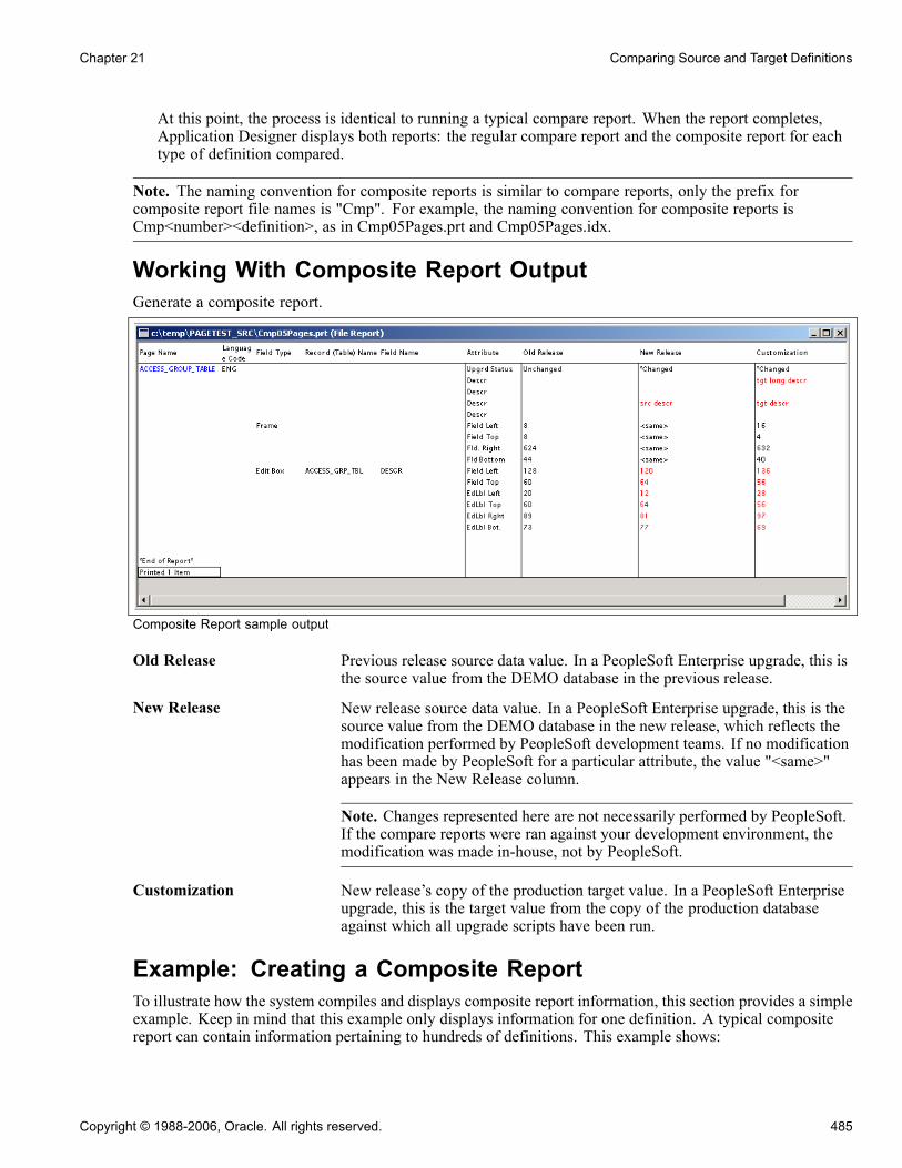
Chapter 21 Comparing Source and Target Definitions
At this point, the process is identical to running a typical compare report. When the report completes,Application Designer displays both reports: the regular compare report and the composite report for eachtype of definition compared.
Note. The naming convention for composite reports is similar to compare reports, only the prefix forcomposite report file names is "Cmp". For example, the naming convention for composite reports isCmp<number><definition>, as in Cmp05Pages.prt and Cmp05Pages.idx.
Working With Composite Report OutputGenerate a composite report.
Composite Report sample output
Old Release Previous release source data value. In a PeopleSoft Enterprise upgrade, this isthe source value from the DEMO database in the previous release.
New Release New release source data value. In a PeopleSoft Enterprise upgrade, this is thesource value from the DEMO database in the new release, which reflects themodification performed by PeopleSoft development teams. If no modificationhas been made by PeopleSoft for a particular attribute, the value "<same>"appears in the New Release column.
Note. Changes represented here are not necessarily performed by PeopleSoft.If the compare reports were ran against your development environment, themodification was made in-house, not by PeopleSoft.
Customization New release’s copy of the production target value. In a PeopleSoft Enterpriseupgrade, this is the target value from the copy of the production databaseagainst which all upgrade scripts have been run.
Example: Creating a Composite ReportTo illustrate how the system compiles and displays composite report information, this section provides a simpleexample. Keep in mind that this example only displays information for one definition. A typical compositereport can contain information pertaining to hundreds of definitions. This example shows:
Copyright © 1988-2006, Oracle. All rights reserved. 485
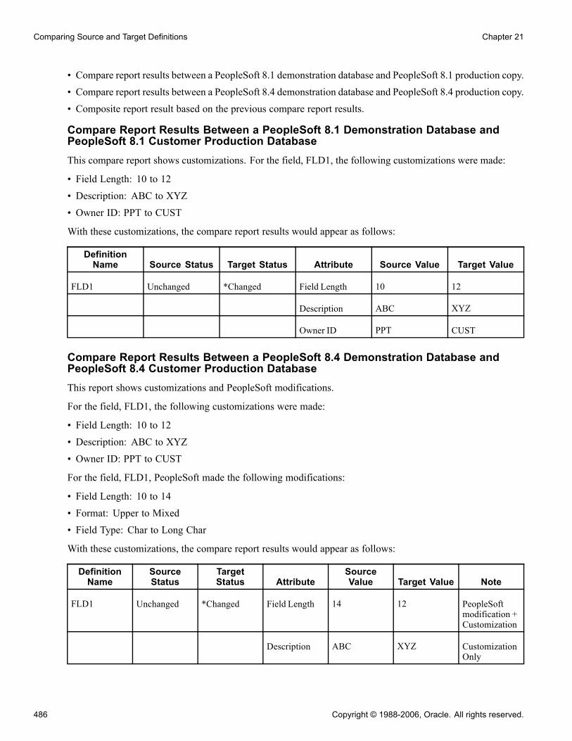
Comparing Source and Target Definitions Chapter 21
• Compare report results between a PeopleSoft 8.1 demonstration database and PeopleSoft 8.1 production copy.• Compare report results between a PeopleSoft 8.4 demonstration database and PeopleSoft 8.4 production copy.• Composite report result based on the previous compare report results.
Compare Report Results Between a PeopleSoft 8.1 Demonstration Database andPeopleSoft 8.1 Customer Production DatabaseThis compare report shows customizations. For the field, FLD1, the following customizations were made:
• Field Length: 10 to 12• Description: ABC to XYZ• Owner ID: PPT to CUST
With these customizations, the compare report results would appear as follows:
DefinitionName Source Status Target Status Attribute Source Value Target Value
FLD1 Unchanged *Changed Field Length 10 12
Description ABC XYZ
Owner ID PPT CUST
Compare Report Results Between a PeopleSoft 8.4 Demonstration Database andPeopleSoft 8.4 Customer Production DatabaseThis report shows customizations and PeopleSoft modifications.
For the field, FLD1, the following customizations were made:
• Field Length: 10 to 12• Description: ABC to XYZ• Owner ID: PPT to CUST
For the field, FLD1, PeopleSoft made the following modifications:
• Field Length: 10 to 14• Format: Upper to Mixed• Field Type: Char to Long Char
With these customizations, the compare report results would appear as follows:
DefinitionName
SourceStatus
TargetStatus Attribute
SourceValue Target Value Note
FLD1 Unchanged *Changed Field Length 14 12 PeopleSoftmodification +Customization
Description ABC XYZ CustomizationOnly
486 Copyright © 1988-2006, Oracle. All rights reserved.

Chapter 21 Comparing Source and Target Definitions
DefinitionName
SourceStatus
TargetStatus Attribute
SourceValue Target Value Note
Owner ID PPT CUST CustomizationOnly
Format Mixed Upper PeopleSoftmodificationonly
Field Type Long Char Char PeopleSoftmodificationonly
Composite Report Result Based on the Previous Compare Report ResultsThe following table is a sample composite report only showing the attributes from the previous comparereports that were changed by both PeopleSoft and a customer.
Definition Name Attribute Old Release New Release Customization
FLD1 Field Length 10 14 12
Descr ABC (same) XYZ
OwnerID PPT (same) CUST
Working with Definition StatusThis section discusses how to:
• Determine definition status.• Compare source status to target status.
Determining Definition StatusPeopleSoft Application Designer defines the status of a definition in the source and the target database.
Unknown Definition has not been compared. This is the default status for alldefinitions inserted manually into a project and the permanent status of allnon-comparison definitions.
Absent The definition was found in the other database, but not in this one. Whenupgrading to a new PeopleSoft release, all new PeopleSoft definitions shouldhave Absent status in the target database and all of your custom definitionsshould have Absent in the source database.
Changed The definition has been compared, the LASTUPDOPRID value is PPLSOFT,and the LASTUPDDTM value is greater than the date/time stamp of thecomparison release database. This indicates that PeopleSoft modified thedefinition since the comparison release.
Copyright © 1988-2006, Oracle. All rights reserved. 487

Comparing Source and Target Definitions Chapter 21
Unchanged The definition has been compared, the LASTUPDOPRID value is PPLSOFT,and the LASTUPDDTM value is less than or equal to the date/time stamp ofthe comparison release database. This indicates that PeopleSoft modified thedefinition prior to the comparison release.
*Changed The definition has been compared, the LASTUPDOPRID value is notPPLSOFT, and the LASTUPDDTM value is greater than the date/time stampof the comparison release database. This indicates that a customer modifiedthe definition since the comparison release.
*Unchanged The definition has been compared, the LASTUPDOPRID value is notPPLSOFT, and the LASTUPDDTM value is less than or equal to the date/timestamp of the comparison release database. This indicates that a customermodified the definition prior to the comparison release.
Same The definition has been compared and is defined the same in both databases.When a definition in one database has this status its counterpart in the otherdatabase will have the equivalent status. This status can be seen whenperforming a project comparison because with a project comparison thedefinitions are static; the project is not repopulated based on the comparisonresults. This status is not seen in a database comparison, because when doingso the project is populated only with definitions defined differently.
Note. Compare by release date is determined by finding the highest release label in common between thesource and target databases. PSRELASE.RELEASELABEL column is searched on both source and targetto find the latest common value between the two. Then PSRELEASE.PSRELEASEDTTM for that label isused for compare by release date for the source and target, respectively. You can override this value to set adifferent release label, or specific compare by date, on the Upgrade Options interface. Only common releaselabels (found on both source and target PSRELEASE table) can be used.
Comparing Source Status to Target StatusThe following table summarizes the possible status, action, and upgrade values that could be applied to asingle definition during the comparison process.
Source Status Target Status Action Other ActionPeopleSoftVanilla
KeepCustomizations
Absent Changed orUnchanged
DELETE None True True
Absent *Changed or*Unchanged
DELETE None False False
Changed Absent COPY None True True
Changed Changed orUnchanged
COPY COPYPROP True True
Changed *Changed or*Unchanged
COPY COPYPROP True False
Unchanged Absent COPY None True True
Unchanged Changed COPY COPYPROP False False
488 Copyright © 1988-2006, Oracle. All rights reserved.

Chapter 21 Comparing Source and Target Definitions
Source Status Target Status Action Other ActionPeopleSoftVanilla
KeepCustomizations
Unchanged Unchanged COPY COPYPROP True True
Unchanged *Changed or*Unchanged
COPY COPYPROP True False
*Changed Absent COPY None True True
*Changed Changed orUnchanged
COPY COPYPROP False True
*Changed *Changed or*Unchanged
COPY COPYPROP True True
*Unchanged Absent COPY None True True
*Unchanged Changed orUnchanged
COPY COPYPROP False True
*Unchanged *Changed COPY COPYPROP False False
*Unchanged *Unchanged COPY COPYPROP True True
Absent Absent None None False False
Same Same None None False False
Unkown Unkown None None False False
The Action, Other Action, PeopleSoft Vanilla, and Keep Customizations are described in the followingsections.
ActionDescribes the upgrade action set for an item.
DELETE (DEL) The item will be deleted from the target database during the copy.
COPY The item will be copied to the target database during the copy.
Other ActionDescribes the action when the system finds differences in record or field definitions.
Note. Used for record and field definitions only.
COPYPROP Copy properties of the item only. That is, for records, only copy the recorddefinition, and not record fields. For fields, copy field definition only, andnot the field labels.
NONE Use the default action instead (DELETE or COPY).
Copyright © 1988-2006, Oracle. All rights reserved. 489

Comparing Source and Target Definitions Chapter 21
PeopleSoft VanillaDescribes the setting of the Upgrade flag for the project item when performing the Vanilla Compare type (seton Upgrade Options).
True Upgrade flag is ON.
False Upgrade flag is OFF. You must override this value in order to have Copyperform the action set in the Action column.
Keep CustomizationDescribes the setting of the Upgrade flag for the project item when performing the Keep CustomizationsCompare type (set on Upgrade Options).
True Upgrade flag is ON.
False Upgrade flag is OFF. You must override this value in order to have Copyperform the action set in the Action column.
Comparing and Merging Page DefinitionsThis section discusses how to:
• Compare and merge page definitions.• Work with the Diff / Merge Page interface.
Comparing and Merging Page DefinitionsTo compare and merge page definitions in the Upgrade view:
1. Open the upgrade project, and make sure that you are in the Upgrade view.2. Open the Pages window within the upgrade project.3. Select the page(s) that you want to compare.4. Right-click on the Pages window to display the context menu.5. Select Diff / Merge Page, and then select one of these options:• From Database: select if you are comparing the current definitions with definitions in another database.After doing so, sign on to the appropriate database using the PeopleSoft Signon window.
• From File: select if you are comparing the current definitions with definitions in a project file. Afterdoing so, navigate to the appropriate file using the Merge from File: Select Project dialog box.
To compare and merge page definitions from the Development view:
1. Open the page definition that you want to compare.2. Select Diff / Merge Page, and then select one of these options:• From Database: select if you are comparing the current definitions with definitions in another database.After doing so, sign on to the appropriate database using the PeopleSoft Signon window.
490 Copyright © 1988-2006, Oracle. All rights reserved.

Chapter 21 Comparing Source and Target Definitions
• From File: select if you are comparing the current definitions with definitions in a project file. Afterdoing so, navigate to the appropriate file using the Merge from File: Select Project dialog box.
Note. For the compare to work, the name of the page in the external database or project file must have thesame name (the same key value) as the page in the current database.
Working with the Page Compare ResultsThis section discusses how to:
• Use the Diff / Merge for Page interface.• Determine differences between page definitions.• Use the Properties panel.• Merge attributes and properties from source to target.
Using the Diff / Merge for Pages InterfaceAfter successfully connecting to the database or file, the interface appears similar to the following example.
Page definition Diff / Merge interface
The PeopleSoft Application Designer displays a Property Value panel to show details about every difference oreach changed page control. To the right, each page is displayed side-by-side enabling the visual comparison.
Note. The pages appear in a read-only state. You cannot make any changes to either page definition fromthe Visual Compare interface.
Determining Differences between Page DefinitionsWhen there are differences between source and target page definitions, the system illustrates this in the Layouttab by surrounding the page field with a red box with a red ’X’ at the top, left-hand corner. The field in whichyou have placed your cursor has a dotted line surrounding it.
Copyright © 1988-2006, Oracle. All rights reserved. 491

Comparing Source and Target Definitions Chapter 21
On the Order tab, page controls that have differences are highlighted in red. Also, if you select a page control,you can see easily if its order is different as the highlighted areas do not match.
Page definition Visual Compare: Order tab
Use the Previous Difference and Next Difference toolbar buttons to navigatequickly between the differences flagged within the active window.
Using the Properties PanelThe Properties panel enables you to view the details regarding the differences between the source and targetpage controls. You can move the panel and dock it to the desired locations.
By placing your cursor into each page control surrounded by a red box, the differences in properties betweenthe source and target definition for that particular page control appear on the Properties panel. You can also usethe TAB key to move from field to field. For page controls that are identical between the source and target,nothing appears in the Properties panel.
Page fields are identified in the Property Value panel by the field ID value displayed on the Order tab.
Property Value Panel
Property Displays the list of properties associated with a particular page field or control.
Note. The properties appearing for different page fields and controls maydiffer. Many of the properties are only used internally by PeopleTools forpage display and position.
[A] <Signed on DatabaseName>
Displays the property values for a page field or control residing in the databaseto which you are currently signed on. In the context of merging pages, thisis the "target" definition.
492 Copyright © 1988-2006, Oracle. All rights reserved.

Chapter 21 Comparing Source and Target Definitions
[B] <DatabaseName/Project File Name>
Displays the property values for a page field or control residing in an externaldatabase or project file. In the context of merging pages, this is the "source"definition.
Note. If needed you can access the page definition properties by selecting File, Object Properties or clickingALT + ENTER.
Merging Attributes and Properties from Source to TargetWhen merging attributes of a page definition it is important to keep in mind where the two definitions you aremerging reside. The database to which you are signed on is A:, or the "target," and the database or projectfile from which you are merging page properties is B:, or the "source."
Use the A and B buttons to control the merging of page definitions between the target and source.
Click B to merge a page field, a control, or the properties of a field, to yourtarget database (A:).Click A to undo any previously merged items from the B page definition.The A button is active only after you have previously merged items from theB page definition.
Note. Before using the A or B buttons, you need to place the cursor on the pagefield or page control that you intend to merge from one definition to the other.
Note. The only way to manipulate the page definitions during the diff / mergeoperation is by using the A and B buttons.
Using the Merge Output WindowAfter running a diff / merge for pages operation, the Merge tab appears in the output window of the ApplicationDesigner work space. The Merge tab enables you to view the status of your merge operation as it recordseach event, such as:
• the initiation of the merge.
• the name of the page being compared.
• the number of differences identified between the two definitions.
• the operations that have occurred (merge Add, undo merge, and so on).
• the name of the saved, merged page definition.
For example:
Opening Visual Merge: MYPAGE(Page)
Comparing [A(ENG,DUT)], [B(ENG,DUT)]
2 difference(s)
(5) Merge: [B](ID:5)–>[A](ID:5)
(4) Merge, Add: [B](ID:13)–>[A](ID:0)
Save [A]:MYPAGE_NEW(Page)
Copyright © 1988-2006, Oracle. All rights reserved. 493
Comparing Source and Target Definitions Chapter 21
Saving Merged DefinitionsAfter you have determined that all of the appropriate page fields and page controls have been merged into yourtarget definition, save your changes. By doing so, the system renames the target definition according to thefollowing naming convention:
<previous_page_name>_NEW
Comparing Definitions for Upgrade Using the Command LineUse the same command line syntax as identified previously to compare definitions.
See Chapter 18, “Using Command Line Parameters,” Understanding PeopleSoft Application DesignerCommand Line Parameters, page 413.
Use the command line statement for an Upgrade Compare process to:
• Connect to the source database.• Connect to the target database.• Perform a project or database compare (based on parameters).• Create compare reports in the specified output directory.
Available ParametersThis table lists all of the available parameters for the upgrade compare statement:
Parameter Description Error Handling
-HIDE Use to hide the PeopleSoftApplication Designer interface.Always use this parameter whenperforming a command lineCompare process.
Required for all project commandline processes.
-CT Source database type.
Enter the type of source databaseto which you’re connecting (forexample, ORACLE, SYBASE, andso on). Choose from the DatabaseType Selection table.
See Appendix B, “ReferencingSelections for Command LineParameters,” Database TypeSelections, page 535.
Required. If the process stops, errormessages are written to the log file(if the log file name parameter isspecified).
494 Copyright © 1988-2006, Oracle. All rights reserved.
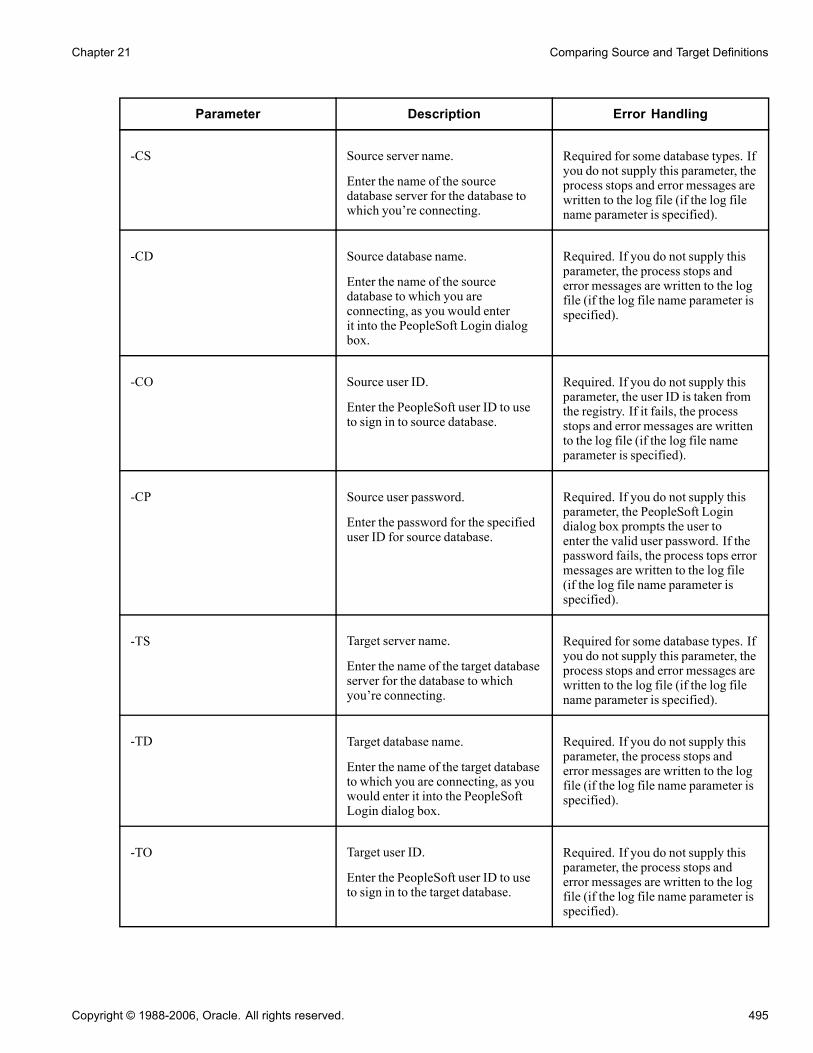
Chapter 21 Comparing Source and Target Definitions
Parameter Description Error Handling
-CS Source server name.
Enter the name of the sourcedatabase server for the database towhich you’re connecting.
Required for some database types. Ifyou do not supply this parameter, theprocess stops and error messages arewritten to the log file (if the log filename parameter is specified).
-CD Source database name.
Enter the name of the sourcedatabase to which you areconnecting, as you would enterit into the PeopleSoft Login dialogbox.
Required. If you do not supply thisparameter, the process stops anderror messages are written to the logfile (if the log file name parameter isspecified).
-CO Source user ID.
Enter the PeopleSoft user ID to useto sign in to source database.
Required. If you do not supply thisparameter, the user ID is taken fromthe registry. If it fails, the processstops and error messages are writtento the log file (if the log file nameparameter is specified).
-CP Source user password.
Enter the password for the specifieduser ID for source database.
Required. If you do not supply thisparameter, the PeopleSoft Logindialog box prompts the user toenter the valid user password. If thepassword fails, the process tops errormessages are written to the log file(if the log file name parameter isspecified).
-TS Target server name.
Enter the name of the target databaseserver for the database to whichyou’re connecting.
Required for some database types. Ifyou do not supply this parameter, theprocess stops and error messages arewritten to the log file (if the log filename parameter is specified).
-TD Target database name.
Enter the name of the target databaseto which you are connecting, as youwould enter it into the PeopleSoftLogin dialog box.
Required. If you do not supply thisparameter, the process stops anderror messages are written to the logfile (if the log file name parameter isspecified).
-TO Target user ID.
Enter the PeopleSoft user ID to useto sign in to the target database.
Required. If you do not supply thisparameter, the process stops anderror messages are written to the logfile (if the log file name parameter isspecified).
Copyright © 1988-2006, Oracle. All rights reserved. 495

Comparing Source and Target Definitions Chapter 21
Parameter Description Error Handling
-TP Target user password.
Enter the password for the specifieduser ID for the target database.
Required. If you do not supply thisparameter, the process stops anderror messages are written to the logfile (if the log file name parameter isspecified).
-LF Log file name.
Enter the name of the file in whicherror messages are logged during thecommand line Upgrade Compareprocess.
Not required. If you do not supplythis parameter, a file is created withthe specified path and name, and allof the error messages are written tothat file.
-PJM Source project name.
Enter the name of the project thatis to be compared from the sourcedatabase to the target database. Thisproject should be available in thesource database before starting thecommand line Upgrade Compareprocess to the target database.
Required. This is the mainparameter that is used internallyby the executable file to identifyan upgrade compare. If you do notsupply this parameter and if yousupply all of the source databaselogin parameters, this executable filestarts the application.
-CL Commit limit
Enter the Commit limit (a numbergreater than 0) for the number ofobjects to be copied or comparedbefore a commit is issued. Example:-CL 150
Not required. The default is 50.
-AF Audit flags on records (0 or 1). Enter1 to keep the target audit flags as is.Enter 0 to take them from the sourcedatabase. Example: -AF 0
Not required. The default is 1.
-PPL Portal registry structures permissionlist references.
Enter 1 to keep the target portalregistry permission list referencesas is. Enter 0 to take them from thesource database. Example: -PPL 0
Not required. The default is 1.
496 Copyright © 1988-2006, Oracle. All rights reserved.

Chapter 21 Comparing Source and Target Definitions
Parameter Description Error Handling
-DDL DDL on records and indexes ( 0or 1). Enter 1 to keep the targetdatabase DDL flags as is. Enter 0 totake them from the source database.When keeping the target databaseDDL, no differences are shown onthe compare report. Example: -DDL0
Not required. The default is 1.
-CFD Chartfield PageField Display Size(0 or 1). Enter 1 to keep the targetdatabase chartfield pagefield displaysize attributes. Enter 0 to take themfrom the source database. Whenkeeping target database attributes,no differences are shown on thecompare report for these attributes.Example -CFD 0
Not required. The default is 1.
-CFF Chartfield Field Format (0 or 1).Enter 1 to keep the target databasechartfield field format attributes.Enter 0 to take them from the sourcedatabase. When keeping targetattributes, no differences are shownon the compare report for theseattributes. Example: -CFF 0
Not required. The default is 1.
-CMT Compare type: project (1) ordatabase (0). Example: -CMT 0
Not required. The default is 1.
-TGT Target Orientation: PeopleSoftvanilla (0) or keep personalization(1).
Not required. The default is 0.
-CBY Comparison By:
To compare by release, enterREL, followed by the releasenumber. To compare by date,enter DAT, followed by adate in the following format:YYYY-MM-DD-HH.MM.SS.sss.Release numbers are included inthe Available Release Numbers list.Example: 2002-02-01-12.00.00.000
Not required. The default is REL.
Copyright © 1988-2006, Oracle. All rights reserved. 497

Comparing Source and Target Definitions Chapter 21
Parameter Description Error Handling
-ROD Report Output Directory.
Enter the report output directorylocation. Example-RODc:\temp\upgreports
Not required. If you do not supplythis parameter, the system uses theReport Output Directory value fromthe Tools, Options General tab.
-OBJ Definition type to compare
List the definition types to compareas numbers with commas asdelimiters, or enter All. Example:-OBJ 0,1
See Appendix B, “ReferencingSelections for Command LineParameters,” Definition TypeSelections, page 535.
Not required. If you do not supplythis parameter, then all of thedefinitions are compared by default.For a project comparison, this refersto all definitions in the project. Fora database comparison, this includesall definitions in the database. Forexample, If you choose records andindexes alone for copying, use theappropriate numbers for records andindexes from the Definition TypeSelection table. For records, thenumber is 0, and for the indexes, thenumber is 1.
-LNG Compare languages.
List the language codes withcommas as delimiters, or enter ALLto select all available languages.For new languages that are notlisted in the Language Selectiontable, use the xlat short name fromthe LANGUAGE_CD field in thetranslate table. For example, if youchoose English and Spanish forcomparing, enter the appropriatecodes for English and Spanish fromthe Language Selection table. ForEnglish, the code is ENG, and forSpanish, the code is ESP. Example:-LNG ENG,ESP
See Appendix B, “ReferencingSelections for Command LineParameters,” Language Selections,page 540.
Not required. If you do not supplythis parameter, then the languagesthat are already set in the projectare used as the default. TheCOMMON language code refersto nonlanguage attributes that arenot translated. Translated attributescan be compared separately fromnontranslated attributes. If you donot specify the COMMON codewhen using -LNG, you compareonly the translated languageattributes.
Changing languages on thecommand line changes the valuesthat are stored with the projectdefinition. Subsequent Copy andCompare processes on the modifiedproject use the new values unlessthey are explicitly changed again inthe upgrade options.
498 Copyright © 1988-2006, Oracle. All rights reserved.

Chapter 21 Comparing Source and Target Definitions
Parameter Description Error Handling
-CMXML Generate browser reports (0 or 1).
This command enables you toenable the option of generatingbrowser reports written to yourreport output directory. This isequivalent to setting the GenerateBrowser Reports options on theReport Options tab on the UpgradeOptions dialog box.
Enter 1 to enable this option, andenter 0 to disable this option.
Example: -CMXML 1
See Chapter 21, “Comparing Sourceand Target Definitions,” Workingwith Browser Reports, page 479.
Not required. The default is 0.
-CMR [0 | 1] Use 0 to disable, 1 to enable,the generation of the CompositeCompare Reports. Parameter is onlyvalid when used in conjunction withthe -PJM option. Ignored otherwise.
Not required. If not used, thencomposite report disabled. Must alsouse –CROD and -CRDB optionswhen using -CMR.
-CROD [directory path] Set path for the Old ReleaseCompare reports when generatingComposite Reports (-CMR 1). Onlyvalid when used in conjunctionwith the -PJM and -CMR 1 options,ignored otherwise.
If not set when generating compositereports (-CMR 1) then its an errorcondition, and processing shouldstop, and an error generated tothe log file. Directory path canbe a local directory, a mappednetwork directory, or a UNC pathspecification.
-CRDB [database name] Pass the value of the Old ReleaseSource Database name whengenerating Composite Reports.This value must match the SourceDatabase name value from the OldRelease Report for each definitiontype. This is to ensure the originalold release report is valid andcontains the expected data. If the oldrelease report source database namefor the current definition type doesnot match the passed value, then anerror message is generated to the logfile, but process continues for otherdefinition types.
Not required.
Copyright © 1988-2006, Oracle. All rights reserved. 499

Comparing Source and Target Definitions Chapter 21
Example: Running an Upgrade Compare ProcessUse this example as a guide for running an Upgrade Compare process:
• Run a database Compare process against the source Microsoft SQL Server database, PTDMO, and thetarget database, PTTST.
• Log process and error messages to c:\temp\compare.log.• Set the commit limit to 150.• Show the audit flag and DDL differences between databases.• Compare records, indexes, pages, queries, and process definitions.• Compare only English and Spanish translations.• Set the database compare type.• Set the target orientation to keep the customizations.• Compare by release 8.40.00.000.• Generate compare reports to the c:\temp\upgreports directory.
PSIDE.EXE −HIDE -CT MICROSFT -CD PTDMO -CO PTDMO -CP PTDMO -PJM PPLTOOLS -TDPTTST -TO PTDMO -TP PTDMO -QUIET -LF C:\TEMP\COMPARE.LOG -CL 150 -AF 0 -DDL 0 -OBJ0,1,5,10,20 -LNG ENG, ESP -CMT 0 -TGT 1 -CBY REL Core 8.40.00.000 -ROD C:\TEMP\UPGREPORTS
500 Copyright © 1988-2006, Oracle. All rights reserved.
CHAPTER 22
Working with Text Definitions and TextFiles During Upgrades
This chapter provides an over view and discusses how to:
• Compare and Merge text definitions.• Set merge properties.• Run a Project PeopleCode diff/merge.
Understanding Comparing Text Definitions and Text FilesPeopleSoft Application Designer enables you to compare the same text definition shared between twodatabases (or one database and a file) as well as the same text file used by different PeopleSoft releases.Similar to the Visual Compare interface for pages, you can view the text definitions or files side-by-side whilethe system detects each difference and clearly indicates the differences using visual queues. During thiscomparison, you choose which lines from each file or definition to carry forward into the merged version.
Note. The merge process and interface is identical for all text definitions and text files.
Text definitions are Application Designer definitions that are comprised of text, or code. They are:
• PeopleCode• SQL• HTML• XSLT
Text files refer to text files used to store program logic or configuration settings within the PeopleSoftsystem. They are:
• COBOL files (.CBL).• Configuration files (.CFG).• Data Mover script files (.DMS).• Initialization files (.INI).• SQR source files (.SQC).• SQL files (.SQL).• SQR report files (.SQR).
Copyright © 1988-2006, Oracle. All rights reserved. 501
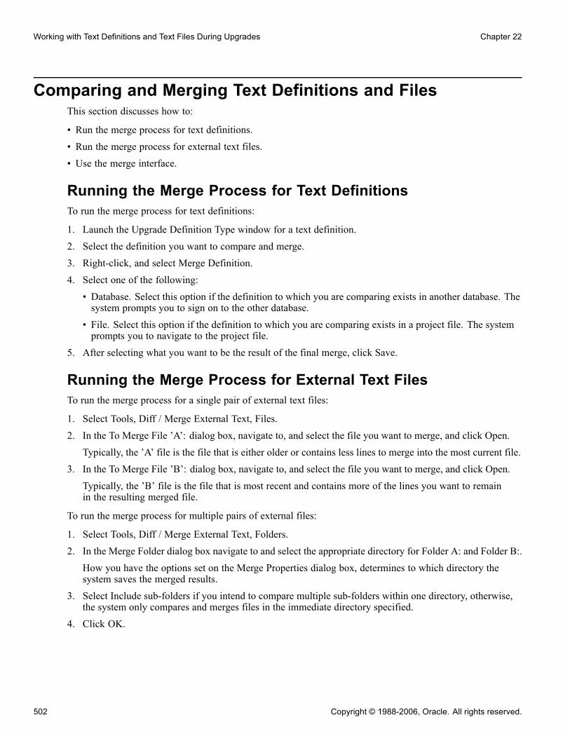
Working with Text Definitions and Text Files During Upgrades Chapter 22
Comparing and Merging Text Definitions and FilesThis section discusses how to:
• Run the merge process for text definitions.
• Run the merge process for external text files.
• Use the merge interface.
Running the Merge Process for Text DefinitionsTo run the merge process for text definitions:
1. Launch the Upgrade Definition Type window for a text definition.2. Select the definition you want to compare and merge.3. Right-click, and select Merge Definition.4. Select one of the following:• Database. Select this option if the definition to which you are comparing exists in another database. Thesystem prompts you to sign on to the other database.
• File. Select this option if the definition to which you are comparing exists in a project file. The systemprompts you to navigate to the project file.
5. After selecting what you want to be the result of the final merge, click Save.
Running the Merge Process for External Text FilesTo run the merge process for a single pair of external text files:
1. Select Tools, Diff / Merge External Text, Files.2. In the To Merge File ’A’: dialog box, navigate to, and select the file you want to merge, and click Open.Typically, the ’A’ file is the file that is either older or contains less lines to merge into the most current file.
3. In the To Merge File ’B’: dialog box, navigate to, and select the file you want to merge, and click Open.Typically, the ’B’ file is the file that is most recent and contains more of the lines you want to remainin the resulting merged file.
To run the merge process for multiple pairs of external files:
1. Select Tools, Diff / Merge External Text, Folders.2. In the Merge Folder dialog box navigate to and select the appropriate directory for Folder A: and Folder B:.How you have the options set on the Merge Properties dialog box, determines to which directory thesystem saves the merged results.
3. Select Include sub-folders if you intend to compare multiple sub-folders within one directory, otherwise,the system only compares and merges files in the immediate directory specified.
4. Click OK.
502 Copyright © 1988-2006, Oracle. All rights reserved.

Chapter 22 Working with Text Definitions and Text Files During Upgrades
Using the Merge InterfaceThe merge interface displays three windows: the A: window, the B: window, and the Output window.
Merge interface for a text definition
Merge interface for an external text file
Copyright © 1988-2006, Oracle. All rights reserved. 503

Working with Text Definitions and Text Files During Upgrades Chapter 22
Working with the A: and B: Windows
Text Type Description
Text definition The A: window displays the definition existing in thedatabase to which you are currently signed on. Code thatappears only in this definition appear in the color specifiedin the Merge Properties for A:.
The label of the A: window adheres to the followingsyntax:
A: Database ’<Database Name>’
The B: window displays the definition existing in thedatabase or file to which you are comparing the definitionexisting in database A:. Code that appears only in thisdefinition appear in the color specified in the MergeProperties for B:.
The label of the B: window adheres to the following syntax:
B: <Database/File> ’<Database/File Name>’
External text file The A: window displays the text file specified in the ToMerge File ’A’ dialog. Code that appears only in this fileappears in the color specified in the Merge Properties forA:.
The label of the A: window adheres to the followingsyntax:
A: <file path>
The B: window displays the text file specified in the ToMerge File ’A’ dialog. Code that appears only in this textfile appears in the color specified in the Merge Propertiesfor B:.
The label of the B: window adheres to the following syntax:
B: <file path>
Note. If you are comparing and merging multiple files ina directory structure (using the Folders option), you viewindividual pairs of files by selecting them in the FolderMerge Diff List window.
Note. In the context of the merge feature, there is not necessarily a concept of "source" and "target." Assigningan "A" and "B" value is used only to distinguish the different locations of definitions and external text files.
Working with the Output WindowThe output window displays what will be the finished result of the merge after clicking Save.
Initially either the A: or B: definition view will appear, depending on what you selected as the Initial OutputView in the Merge Properties dialog. The Initial View window label displays the value you selected.
The output window label also displays the Save To value, which represents the location in which the mergedresults will be saved.
504 Copyright © 1988-2006, Oracle. All rights reserved.

Chapter 22 Working with Text Definitions and Text Files During Upgrades
You can perform simple editing of a line in a text definition appearing in the output window, but you cannotadd new lines.
Note. The Merge tab of the PeopleSoft Application Designer output window, displays any PeopleCodecompile syntax errors. The merged result cannot be saved if there are syntax errors.
Note. While there is an output window for the merge feature, the output window for the PeopleSoftApplication Designer is also visible.
Note. PeopleSoft Application Designer does not provide a method for you to track the change history of a textdefinition or external file. Developers must keep track of the changes made during the merge process.
Moving Lines of Code into the Output Window
Click the arrow button to insert lines of code from window A: or B: into theoutput window. This button only appears next to lines of code in the A: and B:windows that are unique to that definition or file.
Click this button to remove from the output window lines of code that existonly in the A: definition or file.
Click this button to remove from the output window lines of code that existonly in the B: definition or file.
Use the Previous Difference and Next Difference buttons to navigate quicklybetween the differences flagged within the active window.
Saving Merged PeopleCodeAfter you are satisfied with PeopleCode in the output window that you have merged, click Save to save thechanges to the database specified as the Save Output Destination.
After you have successfully saved the merged PeopleCode, to view the merged PeopleCode as it appearsin the Saved Output Destination, click the line in the output window indicating that the PeopleCode wassuccessfully saved.
Saving Merged External FilesAfter you are satisfied with the content of the output window, click Save to save the changes to the filespecified as the Save Output Destination in the Merge Properties. To view the results, navigate to the directorycontaining the file and open it using the appropriate program.
Working with Merge PropertiesThis section discusses how to:
• Access the Merge Properties dialog box.• View and set merge properties.
Copyright © 1988-2006, Oracle. All rights reserved. 505

Working with Text Definitions and Text Files During Upgrades Chapter 22
Accessing the Merge Properties Dialog BoxYou access the Merge Properties dialog box after first running the merge process. Then you select File,Definition Properties.
If you change any properties, and click OK, PeopleSoft Application Designer applies those to the currentmerge results. Your merge property changes are applied to all future merge results.
Viewing and Setting Merge PropertiesThis section discusses how to:
• Set Merge properties.
• View "A" and "B" properties.
Setting Merge PropertiesAccess the Merge Properties dialog box and select the Merge tab.
Merge Properties dialog box: Merge tab
Initial Output View Select the definition you want to appear in the output window of the compareinterface. Typically, you set the Initial Output View to contain the definitionthat would have the most modifications to accept. Either "A" or "B" can beselected.
506 Copyright © 1988-2006, Oracle. All rights reserved.

Chapter 22 Working with Text Definitions and Text Files During Upgrades
Save Output Destination Select the location where the system saves the contents of the merged outputwindow. The location you select appears on the title bar of the output window.
Note. You cannot save the output to a file.
Colors Specify the colors that the system should associate with each definition toenhance readability.
• A Only: Select the color to attribute to text that appears only in definition A.• B Only: Select the color to attribute to text that appears only in definition B.• Common: Select the color to attribute to text that appears in definitionA and B.
View "A" and "B" PropertiesAccess the Merge Properties dialog box and select either the "A" or "B" tab.
Merge Properties dialog box: ”A” tab
The "A" and "B" tabs display the properties for the current A and B definitions, respectively. These settings areread-only.
Note. PeopleCode definitions do not possess description or Owner ID properties, so these properties appearblank for PeopleCode definitions.
Copyright © 1988-2006, Oracle. All rights reserved. 507

Working with Text Definitions and Text Files During Upgrades Chapter 22
Running a Project PeopleCode Diff/MergeThis section provides an overview and discusses how to .
• Run a Project PeopleCode Diff/Merge.
• Use the Project PeopleCode Diff/Merge interface.
Understanding the Project PeopleCode Diff/MergeRunning a Project PeopleCode Diff/Merge enables you to compare all the PeopleCode definitions in yourupgrade project with another database or file simultaneously. If you have numerous PeopleCode definitions tocompare and merge, this feature can save you time.
Note. The Project PeopleCode Diff/Merge feature is only available for PeopleCode definitions. For SQL,HTML, and XSLT definitions, you need to merge each definition separately.
Running a Project PeopleCode Diff/MergeTo run a Project PeopleCode Diff/Merge:
1. Select Tools, Diff/Merge Project PeopleCode.2. Select either:• Database: select this option if you are comparing definitions with another database. The system willprompt you to sign on to the appropriate database.
• File: select this option if you are comparing definitions existing in a file. The system will promptyou to navigate to the appropriate file.
Using the Project PeopleCode Diff/MergeAfter running the Project PeopleCode Diff/Merge process a blank merge interface appears and the PeopleCodeDiff List window appears at the bottom of the Application Designer workspace.
PeopleCode Diff List
The Item column contains the reference to every PeopleCode definition in the project.
The Diff column indicates whether the comparison between the two definitions uncovered any differences. Ifthere is no difference between the two definitions, the word “identical” appears in the Diff column. If there aredifferences between the two definitions, the word “different” appears in the Diff column, and indicates whichdefinition is more recent. If the definition appears in only one location, the Diff column text will read "A only"or "B only.” If the definition is not present in either location the Diff column text will read "Absent in both.”
When differences are found, the system highlights the row in red also. A and B only lines appear in blue.
Double-click a row in the PeopleCode Diff List to populate the merge interface above and view the differencesbetween the two definitions.
508 Copyright © 1988-2006, Oracle. All rights reserved.

Chapter 22 Working with Text Definitions and Text Files During Upgrades
See AlsoChapter 22, “Working with Text Definitions and Text Files During Upgrades,” Using the Merge Interface,page 503
Filtering the Project PeopleCode Diff ListWhen working with numerous PeopleCode definitions, for ease of use you may need to reduce the numberof rows appearing in the diff list. To filter what appears in the diff list, select or deselect these items fromthe View menu.
Show Identical Items Show items that are identical in both data sources.
Show A-Only Items Show items that exist only in the A: data source.
Show B-Only Items Show items that exist only in B: data source.
Show Different Items Show items where a difference is found between the two data sources.
Show Absent Items Show items where a definition is absent in either data source.
Copyright © 1988-2006, Oracle. All rights reserved. 509

Working with Text Definitions and Text Files During Upgrades Chapter 22
510 Copyright © 1988-2006, Oracle. All rights reserved.

CHAPTER 23
Copying Projects and Definitions
This section contains an overview and discusses how to:
• Review upgrade settings.• Copy projects.• Copy Definitions for upgrade using the command line.• Stamp the target database.• Reuse projects.
Reviewing Upgrade SettingsAfter your project is populated with definitions and has been compared (if applicable), review it and checkthe upgrade settings before copying it. To reduce the number of definitions through which you must search,filter out the information that you don’t need to see by setting your view options. Afterwards, you can adjustthe default upgrade settings.
This section discusses how to:
• Select view options.• Select custom view options.• Override upgrade defaults.• Record upgrade settings.
Selecting View OptionsFilter your view of the upgrade definition window by selecting one of the options in the View, Filtering menu.These same options are available in the upgrade pop-up menu in the Filtering menu. The options are:
No Filtering Select to display all definitions.
Tagged for Upgrade Select to display only definitions with the Upgrade check box selected.
Not Tagged for Upgrade Select to display only definitions with the Upgrade check box cleared.
Done Select to display only definitions with the Done check box selected.
Not Done Select to display only definitions with the Done check box cleared.
Custom Filtering Select to open a dialog box in which you can specify which definition statuscombinations to display.
Copyright © 1988-2006, Oracle. All rights reserved. 511

Copying Projects and Definitions Chapter 23
When you apply a filter, the filter type appears in the bar above the upgrade columns.
Selecting Custom View SettingsSelect View, Filtering, Custom Filtering to access the Custom Filtering dialog box, which includes a matrixthat is similar to that found on the Report Filters tab in the Project Properties dialog box.
Custom FilteringSelect the definition status combinations to display in the upgrade definition window.
Custom Filtering dialog box
Report Filter Click to set these options to be the same as your settings on the Report Filtertab in the Project Properties dialog box.
Show objects which areidentical in source andtarget
Select to display definitions with a status combination of Same and Same.This status combination is possible only if you performed a project comparisonand if definitions in the project were defined the same way in the source andtarget. You can never have a Same and Same status combination for definitiontypes on which you performed a database comparison.
Overriding Upgrade DefaultsAfter reviewing your project and its compare reports, you can override the default upgrade column values forany definitions by changing the Upgrade and Action values.
512 Copyright © 1988-2006, Oracle. All rights reserved.

Chapter 23 Copying Projects and Definitions
For example, to preserve a definition that PeopleSoft Application Designer plans to delete from the target(Action is Delete and the Upgrade check box is selected) change the Upgrade value. You can also remove adefinition from the project. This does not delete the definition from the database.
Overriding defaults helps if you want to propagate deletions from one database to another.
This section discusses how to:
• Specify whether action is taken on a single definition.• Specify whether action is taken on a group of definitions.• Specify which action is performed on a definition during a copy.• Remove a definition from a project.• Select and tag definitions for copying or deleting.
Specifying Whether Action is Taken on a Single DefinitionTo specify whether action is taken on a single definition, select or clear the definition’s Upgrade check box.
When the Upgrade check box is selected, the displayed action is performed when you copy the project. If thecheck box is cleared, no action is taken.
Specifying Whether Action is Taken on a Group of DefinitionsTo specify whether an action is taken on a group of definitions:
1. Select a group of definitions.Use the CTRL and SHIFT keys, or select all definitions in the upgrade definition window by clicking thetop, left-hand cell of the grid.
2. Right-click one of the definitions and select one of these options:• Tag for UpgradeSelect to select the Upgrade check boxes for all of the selected definitions.
• Untag for UpgradeSelect to clear the Upgrade check boxes for all of the selected definitions.
Specifying Which Action is Performed on a Definition During a CopyTo specify which action is performed on a definition during a copy:
1. Click the Action cell of the definition.This activates a drop-down list box in the cell.
2. Select Copy or Delete from the drop-down list box.
Remove a Definition From a ProjectTo remove a definition from a project, select the definition and press DEL.
Selecting and Tagging Definitions for Copying or DeletingTo select and tag definitions for copying or deleting:
1. Select the definition rows.2. Right-click one of the definitions and select Set Action.
Copyright © 1988-2006, Oracle. All rights reserved. 513

Copying Projects and Definitions Chapter 23
3. Select Copy or Delete.Your selected definition reflects this change in the Action column. When you upgrade the project, it iscopied or deleted from the target database.You can also select Set Action for Project to tag all of the definitions in a project for a selected action.
Recording Upgrade SettingsAfter you change the default upgrade settings, save the project. You might also want to print a hard-copyrecord of the project in its current state. You can rerun the Compare process (as a project compare) toregenerate new upgrade reports, or you can print the contents of the upgrade definition window to save ahigh-level view of the project.
This section discusses how to:
• Regenerate upgrade reports.• Print the contents of the upgrade definition window.
Regenerating Upgrade ReportsTo regenerate upgrade reports:
1. Set up the reporting filter.2. Perform a project comparison.A project comparison compares only the definitions in the project, not the action and upgrade settings.Your project contents are not altered unless record fields have changed in the target database, in which casethe corresponding changes are made in the project.This comparison generates new upgrade reports that reflect the configured action and upgrade settings.
Printing the Contents of the Upgrade Definition WindowTo print the contents of the upgrade definition window:
1. Open the upgrade definition with the appropriate definition type displayed.To do this, select the appropriate folder in the upgrade view.
2. Select File, Print.The print job is automatically in landscape format.
Copying ProjectsThis section provides an overview of project copy options and discusses how to:
• Copy projects to a target database.• Copy a project to a file.• Copy a project from a file.
514 Copyright © 1988-2006, Oracle. All rights reserved.

Chapter 23 Copying Projects and Definitions
Note. When upgrading from one database to another some migrated images may not display in a browser.To remedy this situation manually clear the cache files in your browser after the project is copied. For moreinformation about clearing the browser cache, refer to the documentation for your internet browser version.
The Copy Project from File and Copy to Project to File menu items are available only to users who haveupgrade security or read-only access to the database. If these menu items are not available to you, contact yoursystem administrator to update your security profile.
Understanding Project Copy OptionsThere are two ways to copy projects to another database:
• Copying a source project directly to a target database to which you are connected.• Copying a source project to a file and then copying the file to a target database.This feature provides more flexibility in moving PeopleTools definitions and projects across databases. Tomove definitions to another database, you copy definitions to a target directory and files instead of anotherdatabase. The directory and files can be local or reside on a file server. These files then become the sourcewhen copying a project from a file. Note, however, that not all definition types that are supported by theCopy to Database process are supported by the Copy to/from File processes. Those that are not supportedmust be migrated using Copy to Database.
See Chapter 20, “Upgrading with PeopleSoft Application Designer,” Definition Types That You CanUpgrade, page 452.
Copying Projects to a Target DatabaseFollow this procedure to copy a project to a target database.
To copy a project:
1. (Optional) Lock target database definitions.Before PeopleSoft Application Designer replaces or deletes a definition in the target database, it checks todetermine whether the definition has a change control lock applied. If so, PeopleSoft Application Designertakes action on that definition if it has been locked by the same user ID that is performing the copy.Consequently, the speed of a copy might be slow because every definition to be deleted or replaced inthe target must be checked.You can avoid the performance degradation by locking all of the database definitions in the target databaseby using the Change Control Administrator dialog box. This sets a flag telling PeopleSoft ApplicationDesigner not to check the lock status of every definition. When all target definitions are locked, thecopy is faster.
2. Deactivate all system tracing.3. Select Tools, Copy Project, To Database from the PeopleSoft Application Designer toolbar.The Target Signon dialog box appears, prompting you to sign in to a target database.
4. Sign in to the target database as you do with any PeopleSoft database.The Copy dialog box appears.
5. In the Copy dialog box, specify the types of definitions to copy and start the Copy process.6. (Optional) Select the Reset Done Flags check box.
Copyright © 1988-2006, Oracle. All rights reserved. 515

Copying Projects and Definitions Chapter 23
Any definition with a selected Done check box is not copied. The first time that you copy a project, all Donecheck boxes are cleared. When you’re repeating a copy due to problems found the first time, however, youmight want to clear the Done check boxes of definitions that were copied incorrectly. Clear all project Donecheck boxes from the Copy dialog box by selecting Reset Done Flags. This option is selected by default.
7. (Optional) Select the Copy Project Definition check box.If you select this check box, the project definition is copied to the target database.
8. Select the definition types to copy.Only the definition types that exist in the project are displayed in the Object Type(s) list. To select alltypes, click Select All. You can also copy one definition type at a time (repeat this procedure each time).
Note. If you copy definition types individually, copy them in the order in which they’re presented in thedialog box. For instance, start with records, then indexes, and so on.
9. Click Copy.As the Copy process runs, a progress indicator appears on the status bar of the dialog box, displaying thedefinition type, the total number of definitions to copy, and the number copied so far.
10. After the copy completes, check for messages.If you find any problems, correct them and repeat the copy.
11. Stamp the database.To track the history of the configuration upgrades, PeopleSoft recommends that you stamp the targetdatabase after each copy.
Copying a Project to Multiple DatabasesWhen copying a project to multiple databases, or multiple PeopleSoft systems, use one of the techniquesdescribed in this section to ensure that version numbers remain in the correct sequence.
• Sign off and re-sign onto Application Designer between each project copy to a new environment. Thisensures the target environment version is being incremented for each copy. If you do not sign off and re-signonto the system, the version from the previous target environment will be incremented in the next targetenvironment, which may result in a version discrepancy.
• Use Change Assistant. You can do this in either Update mode or Upgrade Mode. In Update mode, createmultiple Change Packages and apply them individually, selecting the target environment each time in theApply Wizard. Your target environments must be registered on an EMF hub. In Upgrade mode, createmultiple jobs and run them individually by opening and running each job. When creating the job, thetarget environment is specified.
• Create a batch file with multiple PSIDE command lines: one for each system.
Copying a Project to a FileTo copy a project to a file:
1. Open the project that you want to copy.
2. Select Tools, Copy Project, To File.
The Copy File dialog box appears.
3. Select the objects that you want to copy, and enter the output directory.
516 Copyright © 1988-2006, Oracle. All rights reserved.

Chapter 23 Copying Projects and Definitions
4. Click Copy.If the file already exists, a confirmation dialog box appears asking if you want to overwrite the existingproject. Select Yes to continue and overwrite project or No to cancel the Copy process.The Progress dialog box shows the progress of the Copy process as it copies each definition in the projectto the specified directory. If you click the Cancel button, the system cancels the Copy process. Any filesthat were created by the Copy process are removed from the specified directory. To continue copying aproject, restart the Copy process if it was canceled.When the Copy process completes successfully, a directory with the same name as the current projectis created under the specified export directory. This directory contains the PeopleTools definitions andproject definition in XML file format.
Copying a Project From a FileThe Copy Project From File command in the Tools menu imports PeopleTools definitions and the projectdefinition from a file that was previously copied by using the Copy To File feature.
This section discusses how to:
• Track fixed incidents.• Copy a project that does not exist in the database from a file.• Copy a project that does exist in the database from a file.
Tracking Fixed IncidentsWhen PeopleSoft delivers a software update, it is in the form of a change project file. This project file usuallyincludes enhancements or updates that fix incidents. You can view incident IDs and their dependencies beforeyou copy the file to the target database.
To view incident IDs that were included in the project file:
1. Open the maintenance project that you are planning to copy to the database.2. Click the Project Properties button.3. Select the Update IDs tab.This tab contains a list of update IDs that were fixed and applied to the software.
4. Select the Pre-Requisites tab.This tab contains a list of update IDs that are dependent on other fixes that are being applied. These arevalidated against the target database when you copy the project. If a fix in the Pre-Requisites list hasnot been applied, a message appears, indicating that the target database is missing a dependency. Theonly way to have the system allow you to copy projects that have dependencies that are not applied isto select the Override Pre-Requisites check box.
Note. We can track applied update ID fixes only through the Copy Project From File command in theTools menu. Therefore, every update ID fix that PeopleSoft delivers is in a change project that mustbe copied to your database.
See Enterprise PeopleTools 8.48 PeopleBook: PeopleSoft Software Updates, “Using Change Packages”.
Copying From a File a Project That Does Not Exist in the DatabaseTo copy a project from a file:
Copyright © 1988-2006, Oracle. All rights reserved. 517

Copying Projects and Definitions Chapter 23
1. Select Tools, Copy Project, From File.The Copy From File: Select Project dialog box appears.
2. Browse to locate the project file or select the file from the Projects list.
Note. You can use the Open button to open folders while browsing. It does not open the project fileand begin the copy process.
You can copy only one project from a file at a time.3. Select the project from the projects list by clicking Select or double clicking the project name.The Copy From File dialog box appears.
4. Select whether to use the project definition from the file or the database, and click OK.5. Select the definition types to copy.The Definition Type(s) list shows the definition types that have been exported and are available tobe copied into the database.
6. Select the Override Pre-Requisites check box if required.You can select the Override Pre-Requisites check box if you want the system not to check for projectprerequisites and apply the project regardless of prerequisites that have not been applied.
7. Click Copy.There are two phases to the Import process: content on the XML file is written to the system cache directory(as specified in the PeopleSoft Configuration Manager) under a stage directory for the current database.Then the cache is copied to the database. When the import is complete, the cache files are deleted.The Progress dialog box shows the progress of the Copy process as it copies each definition from theexport directory into the attached database. When the Copy from File process successfully completes, thesystem creates a new project definition from the PeopleTools definitions in the current database.If you click the Cancel button before copying the project, the project becomes invalid and the systemdeletes the project reference from the database.
Note. When copying application packages and Portal Registry Structures, the Progress dialog box maydisplay unexpected counting behavior, making it appear that definitions are being processed more than once.This behavior is expected.
Copying From a File a Project That Does Exist in the DatabaseThe process for copying a project from a file when a project of the same name exists in the database is slightlydifferent. After selecting Tools, Copy Project, From File and a project of the same name already exists in thedatabase to which you are currently signed on, the following dialog box appears.
518 Copyright © 1988-2006, Oracle. All rights reserved.

Chapter 23 Copying Projects and Definitions
Copy From File: prompting for project definition location
This prompt enables you to specify which project definition to use, the one stored in the database to whichyou are signed on or the one stored in the file from which you intend to copy. Keep in mind that the projectdefinition is the metadata of the project and determines which definitions (pages, fields, records, and soon) are members of the project.
File Select this option if you intend to copy the project stored in the file regardlessof any Upgrade Action or Take Action settings in the database.
Note. By selecting this option, you overwrite the project definition of thesame name that previously existed in the database.
Database Select this option if you intend to maintain control of the upgrade projectdefinition stored in the database and manually override any Upgrade Action orTake Action settings.
Copying Definitions for Upgrade Using the Command LineUse the same command line syntax as identified previously to copy definitions.
See Chapter 18, “Using Command Line Parameters,” Understanding PeopleSoft Application DesignerCommand Line Parameters, page 413.
Use the command line statement for Upgrade Copy processes to:
• Connect to the source database.• Connect to the target database.• Copy the project and its objects from the source database to the target database.
Copyright © 1988-2006, Oracle. All rights reserved. 519

Copying Projects and Definitions Chapter 23
If the same project already exists in the target database, you can set the option to overwrite the older projectwith the new project.
Available ParametersThe following table lists all available parameters for the upgrade copy statement:
Parameter Description Error Handling
-HIDE Use to hide the PeopleSoftApplication Designer interface.Always use this parameter whenperforming a command line Copyprocess.
Required for all project commandline processes.
-CT Source database type.
Enter the type of source databaseto which you are connecting (forexample, ORACLE, SYBASE, andso on).
Required. If the process stops, errormessages are written to the log file(if the log file name parameter isspecified).
-CS Source server name.
Enter the name of the sourcedatabase server for the database towhich you’re connecting.
Required for some database types. Ifyou do not supply this parameter, theprocess stops and error messages arewritten to the log file (if the log filename parameter is specified).
-CD Source database name.
Enter the name of the sourcedatabase to which you’reconnecting, as you would enterit into the PeopleSoft Login dialogbox.
Required. If you do not supply thisparameter, the process stop and errormessages are written to the log file(if the log file name parameter isspecified).
-CO Source user ID.
Enter the PeopleSoft user ID to useto sign in to the source database.
Required. If you do not supply thisparameter, the user ID is taken fromthe registry. If it fails, the processstops and error messages are writtento the log file (if the log file nameparameter is specified).
-CP Source user password.
Enter the password for the specifieduser ID for source database.
Required. If you do not supply thisparameter, the PeopleSoft Logindialog box prompts the user to givethe valid password. If it fails, theprocess stops and error messages arewritten to the log file (if the log filename parameter is specified).
520 Copyright © 1988-2006, Oracle. All rights reserved.

Chapter 23 Copying Projects and Definitions
Parameter Description Error Handling
-TS Target server name.
Enter the name of the target databaseserver for the database to whichyou’re connecting.
Required for some database typesand for a Database Copy process(but not used for a Copy To File orCopy From File process). If youdo not supply this parameter, theprocess stops and error messages arewritten to the log file (if the log filename parameter is specified).
-TD Target database name.
Enter the name of the target databaseto which you’re connecting, as youwould enter it into the PeopleSoftLogin dialog box.
Required for a database Copyprocess (but not used for a Copy ToFile or Copy From File process). Ifyou do not supply this parameter, theprocess stops and error messages arewritten to the log file (if the log filename parameter is specified).
-TO Target user ID.
Enter the PeopleSoft user ID to useto sign in to the target database.
Required for a Database Copyprocess (but not used for a Copy ToFile or Copy From File process). Ifyou do not supply this parameter, theprocess stops and error messages arewritten to the log file (if the log filename parameter is specified).
-TP Target user password.
Enter the password for the specifieduser ID for the target database.
Required for a Database Copyprocess (but not used for a Copy ToFile or Copy From File process). Ifyou do not supply this parameter, theprocess stops and error messages arewritten to the log file (if the log filename parameter is specified).
-LF Log file name.
Enter the name of the file in whicherror messages are logged duringthe command line Upgrade Copyprocess.
Not required. If you do not supplythis parameter, a file is created withthe specified path and name, and allof the processing and error messagesare written to that file.
-PJC Source project name.
Enter the name of the project thatis to be copied from the sourcedatabase to the target database.This project should be available inthe source database before startingthe command line Upgrade Copyprocess to target database.
Required for a Database Copyprocess. This is the main parameterthat is used internally by theexecutable file to identify anUpgrade Copy process. If you donot supply this parameter and if yousupply all of the source databaselogin parameters, the executable filestarts the application.
Copyright © 1988-2006, Oracle. All rights reserved. 521
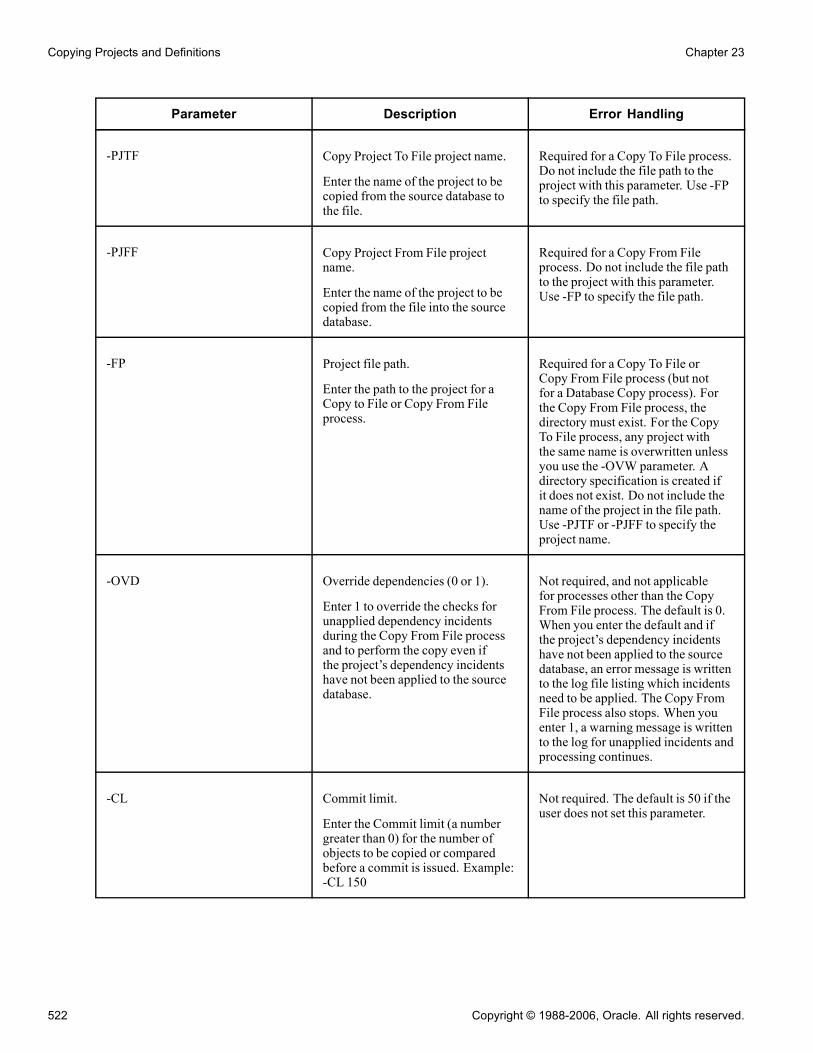
Copying Projects and Definitions Chapter 23
Parameter Description Error Handling
-PJTF Copy Project To File project name.
Enter the name of the project to becopied from the source database tothe file.
Required for a Copy To File process.Do not include the file path to theproject with this parameter. Use -FPto specify the file path.
-PJFF Copy Project From File projectname.
Enter the name of the project to becopied from the file into the sourcedatabase.
Required for a Copy From Fileprocess. Do not include the file pathto the project with this parameter.Use -FP to specify the file path.
-FP Project file path.
Enter the path to the project for aCopy to File or Copy From Fileprocess.
Required for a Copy To File orCopy From File process (but notfor a Database Copy process). Forthe Copy From File process, thedirectory must exist. For the CopyTo File process, any project withthe same name is overwritten unlessyou use the -OVW parameter. Adirectory specification is created ifit does not exist. Do not include thename of the project in the file path.Use -PJTF or -PJFF to specify theproject name.
-OVD Override dependencies (0 or 1).
Enter 1 to override the checks forunapplied dependency incidentsduring the Copy From File processand to perform the copy even ifthe project’s dependency incidentshave not been applied to the sourcedatabase.
Not required, and not applicablefor processes other than the CopyFrom File process. The default is 0.When you enter the default and ifthe project’s dependency incidentshave not been applied to the sourcedatabase, an error message is writtento the log file listing which incidentsneed to be applied. The Copy FromFile process also stops. When youenter 1, a warning message is writtento the log for unapplied incidents andprocessing continues.
-CL Commit limit.
Enter the Commit limit (a numbergreater than 0) for the number ofobjects to be copied or comparedbefore a commit is issued. Example:-CL 150
Not required. The default is 50 if theuser does not set this parameter.
522 Copyright © 1988-2006, Oracle. All rights reserved.

Chapter 23 Copying Projects and Definitions
Parameter Description Error Handling
-AF Audit flags on records (0 or 1).
Enter 1 to keep the target audit flagsas is. Enter 0 to take them from thesource database. Example: -AF 0
Not required. The default is 1.
-DDL Data definition language (DDL) onrecords and indexes (0 or 1).
Enter 1 to keep the target databaseDDL flags as is. Enter 0 to take themfrom the source database. Example:-DDL 0
Not required. The default is 1.
-PPL Portal registry structures permissionlist references.
Enter 1 to keep the target portalregistry permission list referencesas is. Enter 0 to take them from thesource database.
Not required. The default is 1.
-EXP Export project definition (0 or 1).
Enter 1 to export the projectdefinition to the target databasewhen using the Database Copyprocess. Not applicable for CopyProject to File process.
Not required. The default is 1.Any project with the same name isoverwritten with the new projectdefinition.
-OBJ Object types to copy
List the object types as numberswith commas as delimiters. Forexample, if you choose records andindexes alone for copying, use theappropriate numbers for records andindexes from the Definition TypeSelection table. For records, thenumber is 0, and for the indexes, thenumber is 1. Example: -OBJ 0,1
See Appendix B, “ReferencingSelections for Command LineParameters,” Definition TypeSelections, page 535.
Not required. If you do not supplythis parameter, then all of the objectsare copied by default.
-RST Reset done flags (0 or 1).
Enter 1 to reset the done flags beforeinitiating the Copy process. Enter 0to not reset them. Example: -RST 0
Not required. The default is 1.
Copyright © 1988-2006, Oracle. All rights reserved. 523
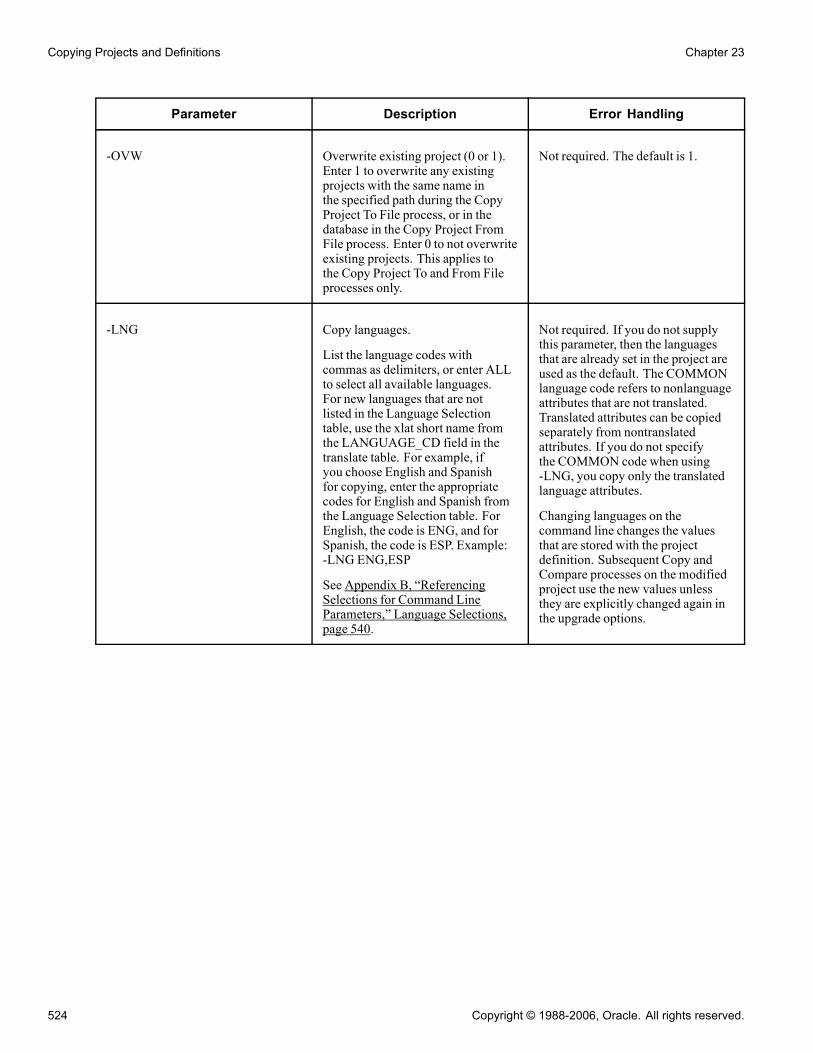
Copying Projects and Definitions Chapter 23
Parameter Description Error Handling
-OVW Overwrite existing project (0 or 1).Enter 1 to overwrite any existingprojects with the same name inthe specified path during the CopyProject To File process, or in thedatabase in the Copy Project FromFile process. Enter 0 to not overwriteexisting projects. This applies tothe Copy Project To and From Fileprocesses only.
Not required. The default is 1.
-LNG Copy languages.
List the language codes withcommas as delimiters, or enter ALLto select all available languages.For new languages that are notlisted in the Language Selectiontable, use the xlat short name fromthe LANGUAGE_CD field in thetranslate table. For example, ifyou choose English and Spanishfor copying, enter the appropriatecodes for English and Spanish fromthe Language Selection table. ForEnglish, the code is ENG, and forSpanish, the code is ESP. Example:-LNG ENG,ESP
See Appendix B, “ReferencingSelections for Command LineParameters,” Language Selections,page 540.
Not required. If you do not supplythis parameter, then the languagesthat are already set in the project areused as the default. The COMMONlanguage code refers to nonlanguageattributes that are not translated.Translated attributes can be copiedseparately from nontranslatedattributes. If you do not specifythe COMMON code when using-LNG, you copy only the translatedlanguage attributes.
Changing languages on thecommand line changes the valuesthat are stored with the projectdefinition. Subsequent Copy andCompare processes on the modifiedproject use the new values unlessthey are explicitly changed again inthe upgrade options.
524 Copyright © 1988-2006, Oracle. All rights reserved.
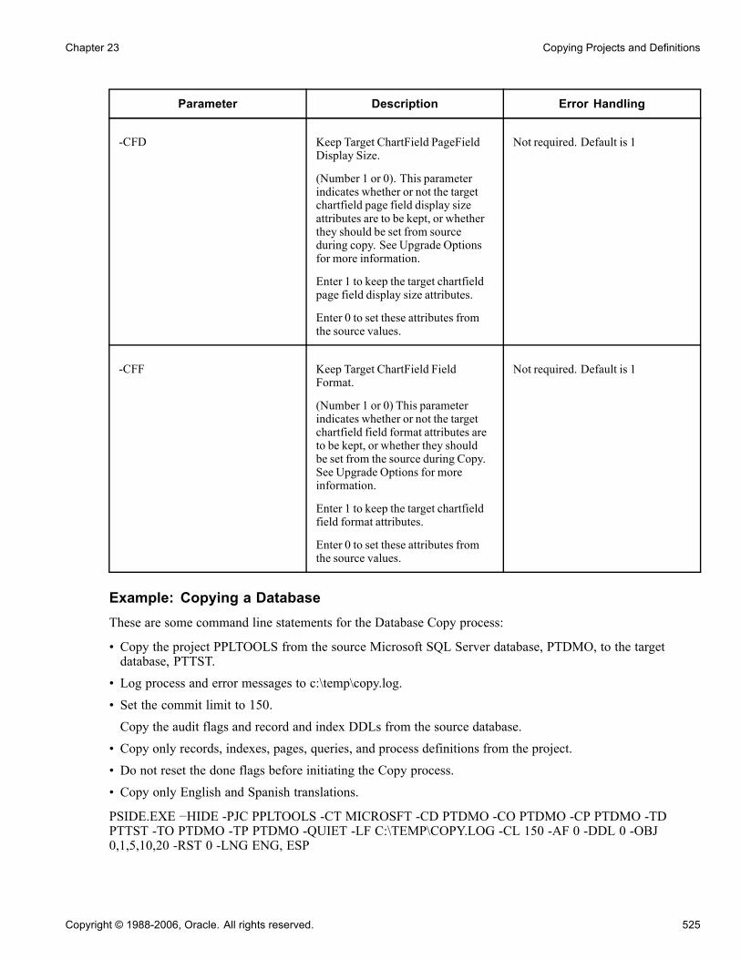
Chapter 23 Copying Projects and Definitions
Parameter Description Error Handling
-CFD Keep Target ChartField PageFieldDisplay Size.
(Number 1 or 0). This parameterindicates whether or not the targetchartfield page field display sizeattributes are to be kept, or whetherthey should be set from sourceduring copy. See Upgrade Optionsfor more information.
Enter 1 to keep the target chartfieldpage field display size attributes.
Enter 0 to set these attributes fromthe source values.
Not required. Default is 1
-CFF Keep Target ChartField FieldFormat.
(Number 1 or 0) This parameterindicates whether or not the targetchartfield field format attributes areto be kept, or whether they shouldbe set from the source during Copy.See Upgrade Options for moreinformation.
Enter 1 to keep the target chartfieldfield format attributes.
Enter 0 to set these attributes fromthe source values.
Not required. Default is 1
Example: Copying a DatabaseThese are some command line statements for the Database Copy process:
• Copy the project PPLTOOLS from the source Microsoft SQL Server database, PTDMO, to the targetdatabase, PTTST.
• Log process and error messages to c:\temp\copy.log.
• Set the commit limit to 150.
Copy the audit flags and record and index DDLs from the source database.
• Copy only records, indexes, pages, queries, and process definitions from the project.
• Do not reset the done flags before initiating the Copy process.
• Copy only English and Spanish translations.
PSIDE.EXE −HIDE -PJC PPLTOOLS -CT MICROSFT -CD PTDMO -CO PTDMO -CP PTDMO -TDPTTST -TO PTDMO -TP PTDMO -QUIET -LF C:\TEMP\COPY.LOG -CL 150 -AF 0 -DDL 0 -OBJ0,1,5,10,20 -RST 0 -LNG ENG, ESP
Copyright © 1988-2006, Oracle. All rights reserved. 525

Copying Projects and Definitions Chapter 23
Example: Copying To FileThese are some command line statements for the Copy to File process:
• Copy the PPLTOOLS project from the Oracle database, PTDMO, by using the PTDMO user ID, to thelocal directory c:\temp\export.A directory named PPLTOOLS is created in c:\temp\export.
• Log progress and error messages to c:\temp\copy.log.
PSIDE.EXE −HIDE -PJTF PPLTOOLS -FP c:\temp\export -CT ORACLE -CD PTDMO -CO PTDMO -CPPTDMO -QUIET -LF c:\temp\copy.log
Example: Copying From FileThese are some command line statements for the Copy From File process.
• Copy the PPLTOOLS project to the DB2 UDB for Linux, Unix, and Windows database, PTDMO, by usingthe user ID PTDMO, from the local directory c:\temp\export.A directory named PPLTOOLS must exist under c:\temp\export.
• Log progress and error messages to c:\temp\copy.log.
PSIDE.EXE −HIDE -PJFF PPLTOOLS -FP c:\temp\export -CT DB2UNIX -CD PTDMO -CO PTDMO -CPPTDMO -QUIET LF c:\temp\copy.log
Stamping the Target DatabaseAfter successfully copying a project into the target database, "stamp" it to reflect the fact that it has changedfrom its previous customer release level. This helps to identify modifications that you make after this versionof the database.
Note. When upgrading to a new PeopleSoft release, this step is required, except that you stamp the databasewith the new PeopleSoft release level, as directed by the upgrade instructions on Customer Connection.
To stamp the target database:
1. Select Tools, Upgrade, Stamp Database.
The Stamp Database dialog box appears.
Use this dialog box to specify and stamp the database with a new customer release level.
2. Enter the appropriate PeopleSoft Release description, service pack level, and customer release value.
Do not change the service pack level unless instructed to do so during a PeopleSoft delivered releaseupgrade.The new customer release value must be greater than or equal to the previous value.
3. Click Stamp.
See AlsoChapter 19, “Using Change Control,” Change Control Stamping, page 434
526 Copyright © 1988-2006, Oracle. All rights reserved.

Chapter 23 Copying Projects and Definitions
Reusing ProjectsPeopleSoft Application Designer enables you to reuse projects. To reuse a project, clear the Done check boxesfor the definitions to be recopied. You might also want to validate the project integrity and delete invaliddefinitions. However, this is not necessary. During a copy, invalid definitions are reported and ignored.
This section discusses how to:
• Validate project integrity.• Reset all Done check boxes.• Reset Done check boxes for a group of definitions.• Reset the Done check box for a single definition.
Validating Project IntegrityTo validate project integrity:
1. Select Tools, Options.2. Select the Validate tab.Use this tab to specify what kind of checks you want to perform during a project validation. This procedurediscusses only project integrity validation.
3. Select the Validate project integrity check box.4. Click OK.5. Select Tools, Validate.A message appears, asking whether you want to delete and report invalid definitions or just to report them.
Note. An invalid definition is any definition in the project with an Add or Replace action that does notexist in the database. PeopleSoft Application Designer does not act on definitions with a Delete action,because it assumes that you want to retain such definitions in the project—regardless of whether they stillexist in the database—for the purpose of deleting the same definition in a target database.
Resetting All Done Check BoxesTo reset all Done check boxes, right-click in the upgrade definition window and select Reset Done Flag. Toreset them for the entire project, select the Reset Project Done Flags option. You can also select Edit, Upgrade,Reset Project Done Flags from the main menu. All Done check boxes for all definitions in the project arecleared.
Resetting Done Check Boxes for a Group of DefinitionsTo reset Done check boxes for a group of definitions:
1. Select a group of definitions.Use the CTRL and SHIFT keys, or select all definitions in the upgrade definition window by clicking thetop, left-hand cell of the grid.
2. Right-click one of the definitions and select Reset Done Flag.
You can also select Edit, Upgrade, Reset Done Flag from the main menu. This clears all Done check boxes forthe selected definitions.
Copyright © 1988-2006, Oracle. All rights reserved. 527

Copying Projects and Definitions Chapter 23
Resetting the Done Check Box for a Single DefinitionTo reset the Done check box for a single definition, clear the Done check box for the definition.
Note. You can only manually clear Done check boxes. You cannot activate these check boxes yourself; theyare automatically selected after a successful copy.
528 Copyright © 1988-2006, Oracle. All rights reserved.

APPENDIX A
Understanding Functional Indexes
This appendix discusses functional indexes for:
• Microsoft SQL Server 2000• DB2/UDB for Linux, UNIX, and Windows• Informix
Functional Indexes for Microsoft SQL Server 2000The following example shows how the key fields are concatenated:
USE FS840U70
go
SET IMPLICIT_TRANSACTIONS ON
go
IF EXISTS (SELECT ’X’ FROM SYSOBJECTS WHERE TYPE = ’U’ AND NAME =
’PS_QE_ALTER_NEW’) DROP TABLE PS_QE_ALTER_NEW
go
CREATE TABLE PS_QE_ALTER_NEW (QE_ALTER_FLD1 NCHAR(1) NOT NULL,
QE_ALTER_FLD2 NCHAR(1) NOT NULL,
QE_ALTER_FLD3 NCHAR(1) NOT NULL,
QE_ALTER_FLD4 NCHAR(10) NOT NULL,
QE_ALTER_FLD5 NCHAR(20) NOT NULL,
QE_ALTER_FLD6 NCHAR(11) NOT NULL,
QE_ALTER_FLD7 NCHAR(1) NOT NULL,
QE_ALTER_FLD8 NCHAR(1) NOT NULL,
QEPC_AGE SMALLINT NOT NULL,
QEPC_FILE_NUM DECIMAL(6, 2) NOT NULL,
QE_BEGIN_DT PSDATE NULL,
QE_BIRTHDATE PSDATE NULL,
QE_31DIGFLD9 DECIMAL(31, 8) NOT NULL,
QE_ANNUAL_PCT DECIMAL(3, 1) NOT NULL,
QE_MS_DTTM1 PSDATETIME NULL,
QE_MS_DTTM2 PSDATETIME NULL,
QE_ALTER_TIMEA PSTIME NULL,
QE_ALTER_TIMEB PSTIME NULL,
MSSCONCATCOL AS QE_ALTER_FLD1 + QE_ALTER_FLD2 + QE_ALTER_FLD3 +
QE_ALTER_FLD4 + QE_ALTER_FLD5 + QE_ALTER_FLD6 + QE_ALTER_FLD7 +
QE_ALTER_FLD8 + CONVERT(NCHAR,QEPC_AGE) + CONVERT(NCHAR
Copyright © 1988-2006, Oracle. All rights reserved. 529

Understanding Functional Indexes Appendix A
,QEPC_FILE_NUM) + CONVERT(NCHAR(16),QE_BEGIN_DT, 109) +
CONVERT(NCHAR(16),QE_BIRTHDATE, 109) + CONVERT(NCHAR,QE_31DIGFLD9) +
CONVERT(NCHAR,QE_ANNUAL_PCT) + CONVERT(NCHAR(16),QE_MS_DTTM1, 109) +
CONVERT(NCHAR(16),QE_MS_DTTM2, 109) + CONVERT(NCHAR(16)
,QE_ALTER_TIMEA, 109))
go
COMMIT
go
SET ARITHABORT ON
go
CREATE UNIQUE CLUSTERED INDEX PS_QE_ALTER_NEW ON PS_QE_ALTER_NEW
(MSSCONCATCOL)
go
CREATE NONCLUSTERED INDEX PSWQE_ALTER_NEW ON PS_QE_ALTER_NEW
(QE_ALTER_FLD1,
QE_ALTER_FLD2,
QE_ALTER_FLD3,
QE_ALTER_FLD4,
QE_ALTER_FLD5,
QE_ALTER_FLD6,
QE_ALTER_FLD7,
QE_ALTER_FLD8,
QEPC_AGE,
QEPC_FILE_NUM,
QE_BEGIN_DT,
QE_BIRTHDATE,
QE_31DIGFLD9,
QE_ANNUAL_PCT,
QE_MS_DTTM1,
QE_MS_DTTM2)
go
COMMIT
Go
DB2/UDB for Linux, UNIX, and WindowsThe following example shows how the key fields are concatenated:
CREATE TABLE PS_QE_ALTER_NEW (QE_ALTER_FLD1 VARGRAPHIC(1) NOT NULL,
QE_ALTER_FLD2 VARGRAPHIC(1) NOT NULL,
QE_ALTER_FLD3 VARGRAPHIC(1) NOT NULL,
QE_ALTER_FLD4 VARGRAPHIC(10) NOT NULL,
QE_ALTER_FLD5 VARGRAPHIC(20) NOT NULL,
QE_ALTER_FLD6 VARGRAPHIC(11) NOT NULL,
QE_ALTER_FLD7 VARGRAPHIC(1) NOT NULL,
QE_ALTER_FLD8 VARGRAPHIC(1) NOT NULL,
QEPC_AGE VARGRAPHIC(8) NOT NULL,
QEPC_FILE_NUM DECIMAL(6, 2) NOT NULL,
530 Copyright © 1988-2006, Oracle. All rights reserved.

Appendix A Understanding Functional Indexes
QE_BEGIN_DT DATE,
QE_BIRTHDATE DATE,
QE_31DIGFLD9 DECIMAL(31, 8) NOT NULL,
QE_ANNUAL_PCT DECIMAL(3, 1) NOT NULL,
QE_MS_DTTM1 TIMESTAMP,
QE_MS_DTTM2 TIMESTAMP,
QE_ALTER_TIMEA TIME,
QE_ALTER_TIMEB TIME,
DBXCONCATCOL GENERATED ALWAYS AS (QE_ALTER_FLD1 || QE_ALTER_FLD2 ||
QE_ALTER_FLD3 || QE_ALTER_FLD4 || QE_ALTER_FLD5 || QE_ALTER_FLD6 ||
QE_ALTER_FLD7 || QE_ALTER_FLD8 || QEPC_AGE ||
VARGRAPHIC(CHAR(QEPC_FILE_NUM)) ||
VALUE(VARGRAPHIC(CHAR(QE_BEGIN_DT)),’’) ||
VALUE(VARGRAPHIC(CHAR(QE_BIRTHDATE)),’’) ||
VARGRAPHIC(CHAR(QE_31DIGFLD9)) || VARGRAPHIC(CHAR(QE_ANNUAL_PCT)) ||
VALUE(VARGRAPHIC(CHAR(QE_MS_DTTM1)),’’) ||
VALUE(VARGRAPHIC(CHAR(QE_MS_DTTM2)),’’) ||
VALUE(VARGRAPHIC(CHAR(QE_ALTER_TIMEA)),’’))) IN PTAPP INDEX IN
PTAPPIDX NOT LOGGED INITIALLY;
COMMIT;
CREATE UNIQUE INDEX PS_QE_ALTER_NEW ON PS_QE_ALTER_NEW (DBXCONCATCOL);
CREATE INDEX PSWQE_ALTER_NEW ON PS_QE_ALTER_NEW (QE_ALTER_FLD1,
QE_ALTER_FLD2,
QE_ALTER_FLD3,
QE_ALTER_FLD4,
QE_ALTER_FLD5,
QE_ALTER_FLD6,
QE_ALTER_FLD7,
QE_ALTER_FLD8,
QEPC_AGE,
QEPC_FILE_NUM,
QE_BEGIN_DT,
QE_BIRTHDATE,
QE_31DIGFLD9,
QE_ANNUAL_PCT,
QE_MS_DTTM1,
QE_MS_DTTM2);
COMMIT;
Functional Indexes for InformixThe following example shows how the key fields are concatenated:
BEGIN WORK;
CREATE TABLE PS_QE_ALTER_NEW (QE_ALTER_FLD1 CHAR(1) NOT NULL,
QE_ALTER_FLD2 CHAR(1) NOT NULL,
QE_ALTER_FLD3 CHAR(1) NOT NULL,
QE_ALTER_FLD4 CHAR(10) NOT NULL,
Copyright © 1988-2006, Oracle. All rights reserved. 531

Understanding Functional Indexes Appendix A
QE_ALTER_FLD5 CHAR(20) NOT NULL,
QE_ALTER_FLD6 CHAR(11) NOT NULL,
QE_ALTER_FLD7 CHAR(1) NOT NULL,
QE_ALTER_FLD8 CHAR(1) NOT NULL,
QEPC_AGE SMALLINT NOT NULL,
QEPC_FILE_NUM DECIMAL(6, 2) NOT NULL,
QE_BEGIN_DT DATE,
QE_BIRTHDATE DATE,
QE_31DIGFLD9 DECIMAL(31, 8) NOT NULL,
QE_ANNUAL_PCT DECIMAL(3, 1) NOT NULL,
QE_MS_DTTM1 DATETIME YEAR TO FRACTION(3),
QE_MS_DTTM2 DATETIME YEAR TO FRACTION(3),
QE_ALTER_TIMEA DATETIME HOUR TO FRACTION(3),
QE_ALTER_TIMEB DATETIME HOUR TO FRACTION(3)) IN PTAPP LOCK MODE ROW;
REVOKE ALL ON PS_QE_ALTER_NEW FROM PUBLIC;
COMMIT;
BEGIN WORK;
CREATE FUNCTION PS_QE_ALTER_NEW_SP1(
QE_ALTER_FLD1 CHAR(1),
QE_ALTER_FLD2 CHAR(1),
QE_ALTER_FLD3 CHAR(1),
QE_ALTER_FLD4 CHAR(10),
QE_ALTER_FLD5 CHAR(20),
QE_ALTER_FLD6 CHAR(11),
QE_ALTER_FLD7 CHAR(1),
QE_ALTER_FLD8 CHAR(1),
QEPC_AGE SMALLINT,
QEPC_FILE_NUM DECIMAL,
QE_BEGIN_DT DATE,
QE_BIRTHDATE DATE,
QE_31DIGFLD9 DECIMAL,
QE_ANNUAL_PCT DECIMAL,
QE_MS_DTTM1 DATETIME YEAR TO FRACTION(3),
QE_MS_DTTM2 DATETIME YEAR TO FRACTION(3))
RETURNING VARCHAR(166) WITH (NOT VARIANT);
RETURN QE_ALTER_FLD1||
QE_ALTER_FLD2||
QE_ALTER_FLD3||
QE_ALTER_FLD4||
QE_ALTER_FLD5||
QE_ALTER_FLD6||
QE_ALTER_FLD7||
QE_ALTER_FLD8||
QEPC_AGE||
QEPC_FILE_NUM||
QE_BEGIN_DT||
QE_BIRTHDATE||
QE_31DIGFLD9||
QE_ANNUAL_PCT||
QE_MS_DTTM1||
532 Copyright © 1988-2006, Oracle. All rights reserved.

Appendix A Understanding Functional Indexes
QE_MS_DTTM2;
END FUNCTION;
CREATE FUNCTION PS_QE_ALTER_NEW_SP2(
QE_ALTER_TIMEA DATETIME HOUR TO FRACTION(3))
RETURNING VARCHAR(15) WITH (NOT VARIANT);
RETURN QE_ALTER_TIMEA;
END FUNCTION;
CREATE UNIQUE INDEX PS_QE_ALTER_NEW ON PS_QE_ALTER_NEW
(PS_QE_ALTER_NEW_SP1(
QE_ALTER_FLD1,
QE_ALTER_FLD2,
QE_ALTER_FLD3,
QE_ALTER_FLD4,
QE_ALTER_FLD5,
QE_ALTER_FLD6,
QE_ALTER_FLD7,
QE_ALTER_FLD8,
QEPC_AGE,
QEPC_FILE_NUM,
QE_BEGIN_DT,
QE_BIRTHDATE,
QE_31DIGFLD9,
QE_ANNUAL_PCT,
QE_MS_DTTM1,
QE_MS_DTTM2),
PS_QE_ALTER_NEW_SP2(
QE_ALTER_TIMEA)) IN FS840IDX;
CREATE INDEX PSWQE_ALTER_NEW ON PS_QE_ALTER_NEW (QE_ALTER_FLD1,
QE_ALTER_FLD2,
QE_ALTER_FLD3,
QE_ALTER_FLD4,
QE_ALTER_FLD5,
QE_ALTER_FLD6,
QE_ALTER_FLD7,
QE_ALTER_FLD8,
QEPC_AGE,
QEPC_FILE_NUM,
QE_BEGIN_DT,
QE_BIRTHDATE,
QE_31DIGFLD9,
QE_ANNUAL_PCT,
QE_MS_DTTM1,
QE_MS_DTTM2) IN FS840IDX;
COMMIT;
Copyright © 1988-2006, Oracle. All rights reserved. 533

Understanding Functional Indexes Appendix A
534 Copyright © 1988-2006, Oracle. All rights reserved.

APPENDIX B
Referencing Selections for CommandLine Parameters
This appendix lists various values that are useful when specifying command line parameters. Specifically, thesetables are referenced:
• Database type selections.
• Definition type selections.
• Language selections.
• Available release numbers.
Database Type SelectionsUse the following database types:
Database Database Description
DB2ODBC DB2 UDB for OS/390 and z/OS
DB2UNIX DB2 UDB for Linux, Unix, andWindows
INFORMIX Informix
MICROSFT Microsoft SQL Server
ORACLE Oracle
SYBASE Sybase
Definition Type SelectionsUse the following numbers to describe the corresponding definition:
Copyright © 1988-2006, Oracle. All rights reserved. 535

Referencing Selections for Command Line Parameters Appendix B
Number Definition Description
0 Record
1 Index
2 Field
3 Format definition
4 Translate
5 Page
6 Menu
7 Components
8 Record PeopleCode
9 Menu PeopleCode
10 Query
11 Tree structure
12 Tree*
13 Access group*
14 Color
15 Style
16 Not used
17 Business process
18 Activity
536 Copyright © 1988-2006, Oracle. All rights reserved.

Appendix B Referencing Selections for Command Line Parameters
Number Definition Description
19 Role*
20 Process definition
21 Process server
22 Process type
23 Process job
24 Process recurrence
25 Message catalog entries*
26 Dimension*
27 Cube definitions*
28 Cube instance definitions*
29 Business interlink
30 SQL definition
31 File layout definition
32 Component interfaces
33 Application Engine program
34 Application Engine section
35 Message node
36 Message channel
37 Message definition
Copyright © 1988-2006, Oracle. All rights reserved. 537

Referencing Selections for Command Line Parameters Appendix B
Number Definition Description
38 Approval rule set
39 Message PeopleCode
40 Subscription PeopleCode
41 Not used
42 Component interface PeopleCode
43 Application engine PeopleCode
44 Page PeopleCode
45 Page field PeopleCode
46 Component PeopleCode
47 Component record PeopleCode
48 Component record field PeopleCode
49 Image
50 Style sheet
51 HTML
52 Not used
53 Permission list
54 Portal registry definitions
55 Portal registry structures
56 URL definitions
538 Copyright © 1988-2006, Oracle. All rights reserved.

Appendix B Referencing Selections for Command Line Parameters
Number Definition Description
57 Application Packages
58 Application Package PeopleCode
59 Portal Registry User homepage
60 Problem type definition
61 Archive templates (deprecated in PeopleTools release 8.44 and above).
62 XSLT
63 Portal Registry User Favorite
64 Mobile page
65 Relationships
66 Component Interface Property PeopleCode**
67 Optimization Models***
68 File References***
69 File Reference Type Code***
70 Archive object definitions***
71 Archive Templates (Type 2)***
72 Diagnostic Plug-Ins***
* These definition types do not have Copy To File or Copy From File process support.
** This definition type is supported only in PeopleTools 8.42 and later.
*** These definition types are supported only in PeopleTools 8.44 and later.
Copyright © 1988-2006, Oracle. All rights reserved. 539

Referencing Selections for Command Line Parameters Appendix B
Language SelectionsUse the following codes to describe the supported languages:
Code Language Description
CFR Canadian French
DAN Danish
DUT Dutch
ENG English
ESP Spanish
FRA French
GER German
GRK Greek
ITA Italian
JPN Japanese
KOR Korean
MAY Bhasa Malay
POL Polish
POR Portuguese
SVE Swedish
THA Thai
ZHS Simplified Chinese
540 Copyright © 1988-2006, Oracle. All rights reserved.

Appendix B Referencing Selections for Command Line Parameters
Code Language Description
ZHT Traditional Chinese
COMMON Nonlanguage attributes
Available Release NumbersThe available release numbers include:
• Core 5.10.00.000• Core 6.00.00.000• Core 6.10.00.000• Core 7.00.00.000• Core 7.50.00.000• Core 8.00.00.000• Core 8.10.00.000• Core 8.40.00.000
Copyright © 1988-2006, Oracle. All rights reserved. 541

Referencing Selections for Command Line Parameters Appendix B
542 Copyright © 1988-2006, Oracle. All rights reserved.

APPENDIX C
Using Default Style Classes
This appendix provides an overview of default style classes.
Default Style ClassesThis table lists the default style classes that are shipped with your system, the sub style to which each belongs,and a brief description of the default style:
Style Class Name Sub Style Description
EDGE PTSTYLEDEF *Default PeopleSoft PureInternet Architecturenavigation.
HILEFT1 PTSTYLEDEF *Default PeopleSoft PureInternet Architecturenavigation
HILEFT2 PTSTYLEDEF *Default PeopleSoft PureInternet Architecturenavigation.
KNOCKOUT PTSTYLEDEF *Portal administration leftnavigation.
LEVEL1 PTSTYLEDEF *Default PeopleSoft PureInternet Architecturenavigation.
LEVEL2 PTSTYLEDEF *Default PeopleSoft PureInternet Architecturenavigation.
LEVEL3 PTSTYLEDEF *Default PeopleSoft PureInternet Architecturenavigation.
Copyright © 1988-2006, Oracle. All rights reserved. 543

Using Default Style Classes Appendix C
Style Class Name Sub Style Description
MID PTSTYLEDEF Links at the first level of thePeopleSoft Pure InternetArchitecture navigation.
MUTE PTSTYLEDEF Descriptive text in thePeopleSoft Pure InternetArchitecture navigation.
PAADDITIONALINSTRUCTIONS PSALTERNATE Additional instructions on thepage (slightly smaller font).
PABACKGROUNDINVISIBLE PSALTERNATE Body background of hiddengroup boxes and grids.
PABOLDBLUETEXT PSALTERNATE Strong emphasis for text on apage.
PABOLDTEXT PSALTERNATE Field value emphasis.
PACALENDARDAYNUM PSALTERNATE Text for numeric days oncalendars.
PACALENDARDAYNUMDISABLED PSALTERNATE Text for numeric days oncalendars (disabled state).
PACFGRIDFOOT PSALTERNATE Footer borders for ChartFieldgrids.
PACFGRIDLABEL PSALTERNATE Header label background forChartField grids.
PAERRORTEXT PSALTERNATE Inline error message text fonttype, color, and size.
PAEXAMPLE PSALTERNATE Smaller font size todemonstrate an example.
PAEXPANDCOLLAPSE PSALTERNATE Expandable and collapsiblearea borders.
544 Copyright © 1988-2006, Oracle. All rights reserved.
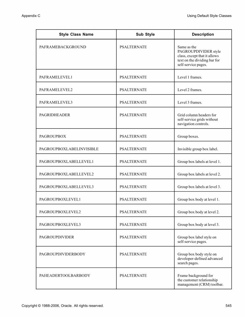
Appendix C Using Default Style Classes
Style Class Name Sub Style Description
PAFRAMEBACKGROUND PSALTERNATE Same as thePAGROUPDIVIDER styleclass, except that it allowstext on the dividing bar forself-service pages.
PAFRAMELEVEL1 PSALTERNATE Level 1 frames.
PAFRAMELEVEL2 PSALTERNATE Level 2 frames.
PAFRAMELEVEL3 PSALTERNATE Level 3 frames.
PAGRIDHEADER PSALTERNATE Grid column headers forself-service grids withoutnavigation controls.
PAGROUPBOX PSALTERNATE Group boxes.
PAGROUPBOXLABELINVISIBLE PSALTERNATE Invisible group box label.
PAGROUPBOXLABELLEVEL1 PSALTERNATE Group box labels at level 1.
PAGROUPBOXLABELLEVEL2 PSALTERNATE Group box labels at level 2.
PAGROUPBOXLABELLEVEL3 PSALTERNATE Group box labels at level 3.
PAGROUPBOXLEVEL1 PSALTERNATE Group box body at level 1.
PAGROUPBOXLEVEL2 PSALTERNATE Group box body at level 2.
PAGROUPBOXLEVEL3 PSALTERNATE Group box body at level 3.
PAGROUPDIVIDER PSALTERNATE Group box label style onself-service pages.
PAGROUPDIVIDERBODY PSALTERNATE Group box body style ondeveloper-defined advancedsearch pages.
PAHEADERTOOLBARBODY PSALTERNATE Frame background forthe customer relationshipmanagement (CRM) toolbar.
Copyright © 1988-2006, Oracle. All rights reserved. 545

Using Default Style Classes Appendix C
Style Class Name Sub Style Description
PAHEADERTOOLBARFRAME PSALTERNATE Frame borders for the CRMtoolbar.
PAHORIZONTALRULELEVEL1 PSALTERNATE Horizontal rule at level 1.
PAHORIZONTALRULELEVEL2 PSALTERNATE Horizontal rule at level 2.
PAHORIZONTALRULELEVEL3 PSALTERNATE Horizontal rule at level 3.
PAHYPERLINKDESCR PSALTERNATE Text description for links onapplication homepages.
PAHYPERLINKERRSTAT PSALTERNATE Links conveying an error status(use with image).
PAHYPERLINKLVL1ODD PSALTERNATE Link style for grid odd rowsthat use the PeopleCode styleproperty.
PAHYPERLINKSUCCESSSTAT PSALTERNATE Links conveying a successfulstatus (use with image).
PAHYPERLINKWARNSTAT PSALTERNATE Links conveying a warningstatus (use with image).
PALEGENDBACKGROUND PSALTERNATE Group box body color forlegends on pages.
PALEVEL0PRIMARY PSALTERNATE Level 0, high-level key data onself-service pages.
PALEVEL0SECONDARY PSALTERNATE Additional fields to identify theobject.
PAPAGEINSTRUCTIONS PSALTERNATE Text instructions on the top ofthe page.
PAPAGETITLE PSALTERNATE Page title.
PASEARCHBOXBODY PSALTERNATE Group boxes around searchcriteria.
546 Copyright © 1988-2006, Oracle. All rights reserved.
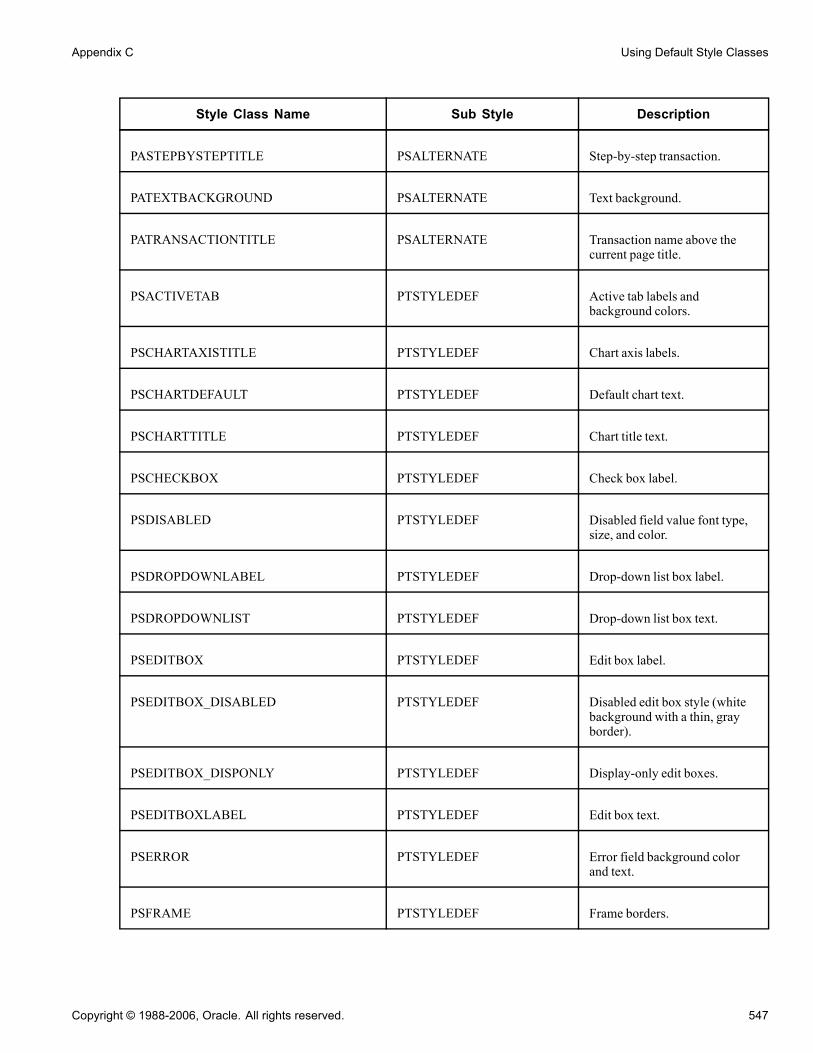
Appendix C Using Default Style Classes
Style Class Name Sub Style Description
PASTEPBYSTEPTITLE PSALTERNATE Step-by-step transaction.
PATEXTBACKGROUND PSALTERNATE Text background.
PATRANSACTIONTITLE PSALTERNATE Transaction name above thecurrent page title.
PSACTIVETAB PTSTYLEDEF Active tab labels andbackground colors.
PSCHARTAXISTITLE PTSTYLEDEF Chart axis labels.
PSCHARTDEFAULT PTSTYLEDEF Default chart text.
PSCHARTTITLE PTSTYLEDEF Chart title text.
PSCHECKBOX PTSTYLEDEF Check box label.
PSDISABLED PTSTYLEDEF Disabled field value font type,size, and color.
PSDROPDOWNLABEL PTSTYLEDEF Drop-down list box label.
PSDROPDOWNLIST PTSTYLEDEF Drop-down list box text.
PSEDITBOX PTSTYLEDEF Edit box label.
PSEDITBOX_DISABLED PTSTYLEDEF Disabled edit box style (whitebackground with a thin, grayborder).
PSEDITBOX_DISPONLY PTSTYLEDEF Display-only edit boxes.
PSEDITBOXLABEL PTSTYLEDEF Edit box text.
PSERROR PTSTYLEDEF Error field background colorand text.
PSFRAME PTSTYLEDEF Frame borders.
Copyright © 1988-2006, Oracle. All rights reserved. 547
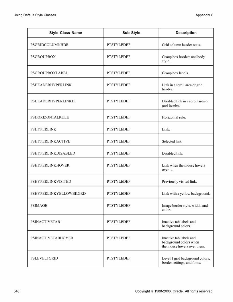
Using Default Style Classes Appendix C
Style Class Name Sub Style Description
PSGRIDCOLUMNHDR PTSTYLEDEF Grid column header texts.
PSGROUPBOX PTSTYLEDEF Group box borders and bodystyle.
PSGROUPBOXLABEL PTSTYLEDEF Group box labels.
PSHEADERHYPERLINK PTSTYLEDEF Link in a scroll area or gridheader.
PSHEADERHYPERLINKD PTSTYLEDEF Disabled link in a scroll area orgrid header.
PSHORIZONTALRULE PTSTYLEDEF Horizontal rule.
PSHYPERLINK PTSTYLEDEF Link.
PSHYPERLINKACTIVE PTSTYLEDEF Selected link.
PSHYPERLINKDISABLED PTSTYLEDEF Disabled link.
PSHYPERLINKHOVER PTSTYLEDEF Link when the mouse hoversover it.
PSHYPERLINKVISITED PTSTYLEDEF Previously visited link.
PSHYPERLINKYELLOWBKGRD PTSTYLEDEF Link with a yellow background.
PSIMAGE PTSTYLEDEF Image border style, width, andcolors.
PSINACTIVETAB PTSTYLEDEF Inactive tab labels andbackground colors.
PSINACTIVETABHOVER PTSTYLEDEF Inactive tab labels andbackground colors whenthe mouse hovers over them.
PSLEVEL1GRID PTSTYLEDEF Level 1 grid background colors,border settings, and fonts.
548 Copyright © 1988-2006, Oracle. All rights reserved.
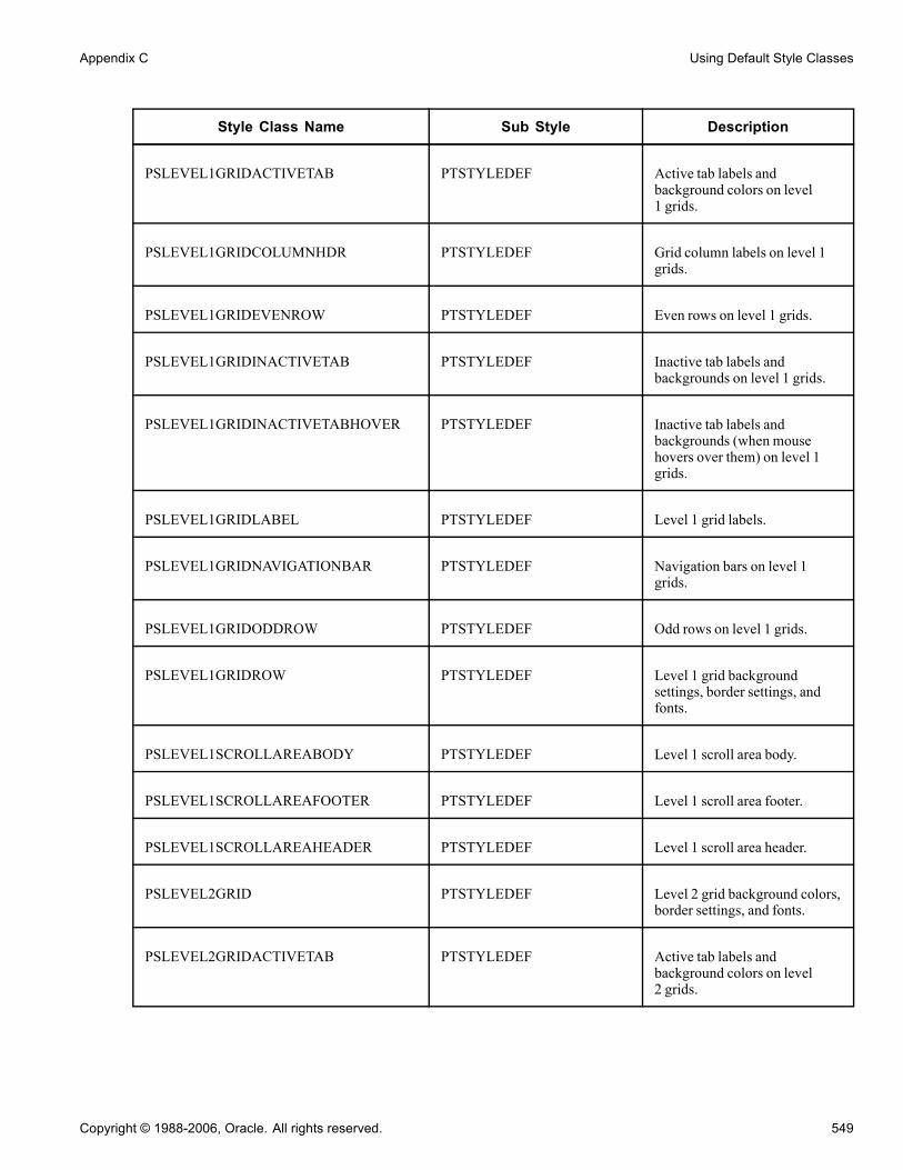
Appendix C Using Default Style Classes
Style Class Name Sub Style Description
PSLEVEL1GRIDACTIVETAB PTSTYLEDEF Active tab labels andbackground colors on level1 grids.
PSLEVEL1GRIDCOLUMNHDR PTSTYLEDEF Grid column labels on level 1grids.
PSLEVEL1GRIDEVENROW PTSTYLEDEF Even rows on level 1 grids.
PSLEVEL1GRIDINACTIVETAB PTSTYLEDEF Inactive tab labels andbackgrounds on level 1 grids.
PSLEVEL1GRIDINACTIVETABHOVER PTSTYLEDEF Inactive tab labels andbackgrounds (when mousehovers over them) on level 1grids.
PSLEVEL1GRIDLABEL PTSTYLEDEF Level 1 grid labels.
PSLEVEL1GRIDNAVIGATIONBAR PTSTYLEDEF Navigation bars on level 1grids.
PSLEVEL1GRIDODDROW PTSTYLEDEF Odd rows on level 1 grids.
PSLEVEL1GRIDROW PTSTYLEDEF Level 1 grid backgroundsettings, border settings, andfonts.
PSLEVEL1SCROLLAREABODY PTSTYLEDEF Level 1 scroll area body.
PSLEVEL1SCROLLAREAFOOTER PTSTYLEDEF Level 1 scroll area footer.
PSLEVEL1SCROLLAREAHEADER PTSTYLEDEF Level 1 scroll area header.
PSLEVEL2GRID PTSTYLEDEF Level 2 grid background colors,border settings, and fonts.
PSLEVEL2GRIDACTIVETAB PTSTYLEDEF Active tab labels andbackground colors on level2 grids.
Copyright © 1988-2006, Oracle. All rights reserved. 549

Using Default Style Classes Appendix C
Style Class Name Sub Style Description
PSLEVEL2GRIDCOLUMNHDR PTSTYLEDEF Grid column labels on level 2grids.
PSLEVEL2GRIDEVENROW PTSTYLEDEF Even rows on level 2 grids.
PSLEVEL2GRIDINACTIVETAB PTSTYLEDEF Inactive tab labels andbackgrounds on level 2 grids.
PSLEVEL2GRIDINACTIVETABHOVER PTSTYLEDEF Inactive tab labels andbackgrounds (when mousehovers over it) on level 2 grids.
PSLEVEL2GRIDLABEL PTSTYLEDEF Labels on level 2 grids.
PSLEVEL2GRIDNAVIGATIONBAR PTSTYLEDEF Navigation bars on level 2grids.
PSLEVEL2GRIDODDROW PTSTYLEDEF Odd rows on level 2 grids.
PSLEVEL2GRIDROW PTSTYLEDEF Level 2 grid backgroundsettings, border settings, andfonts.
PSLEVEL2SCROLLAREABODY PTSTYLEDEF Level 2 scroll area body.
PSLEVEL2SCROLLAREAFOOTER PTSTYLEDEF Level 2 scroll area footer.
PSLEVEL2SCROLLAREAHEADER PTSTYLEDEF Level 2 scroll area header.
PSLEVEL3GRID PTSTYLEDEF Level 3 grid backgroundsettings, border settings, andfonts.
PSLEVEL3GRIDACTIVETAB PTSTYLEDEF Active tab labels andbackground colors on level3 grids.
PSLEVEL3GRIDCOLUMNHDR PTSTYLEDEF Grid column labels on level 3grids.
PSLEVEL3GRIDEVENROW PTSTYLEDEF Even rows on level 3 grids.
550 Copyright © 1988-2006, Oracle. All rights reserved.

Appendix C Using Default Style Classes
Style Class Name Sub Style Description
PSLEVEL3GRIDINACTIVETAB PTSTYLEDEF Inactive tab labels andbackgrounds on level 3 grids.
PSLEVEL3GRIDINACTIVETABHOVER PTSTYLEDEF Inactive tab labels andbackgrounds (when the mousehovers over them) on level 3grids .
PSLEVEL3GRIDLABEL PTSTYLEDEF Labels on level 3 grids.
PSLEVEL3GRIDNAVIGATIONBAR PTSTYLEDEF Navigation bars on level 3grids.
PSLEVEL3GRIDODDROW PTSTYLEDEF Odd rows on level 3 grids.
PSLEVEL3GRIDROW PTSTYLEDEF Level 3 grid backgroundsettings, border settings, andfonts.
PSLEVEL3SCROLLAREABODY PTSTYLEDEF Level 3 scroll area body.
PSLEVEL3SCROLLAREAFOOTER PTSTYLEDEF Level 3 scroll area footer.
PSLEVEL3SCROLLAREAHEADER PTSTYLEDEF Level 3 scroll area header.
PSLONGEDITBOX PTSTYLEDEF Long edit box data.
PSLONGEDITLABEL PTSTYLEDEF Long edit box labels.
PSMULTILANG PTSTYLEDEF Multilingual field background.
PSNAVPARENTLINK PTSTYLEDEF Left navigation link color.
PSPAGE PTSTYLEDEF Page background color andmargins.
PSPAGECUST PTSTYLEDEF Shaded background for pagecustomization image.
PSPROCESSING PTSTYLEDEF Processing messagebackground color.
Copyright © 1988-2006, Oracle. All rights reserved. 551

Using Default Style Classes Appendix C
Style Class Name Sub Style Description
PSPSMALLTEXT PTSTYLEDEF Footer text font type, size,weight, and color.
PSPUSHBUTTON PTSTYLEDEF Push button labels andbackground.
PSPUSHBUTTONDISABLED PTSTYLEDEF Disabled push button labels andbackground color.
PSRADIOBUTTON PTSTYLEDEF Radio buttons.
PSSRCHCHECKBOX PTSTYLEDEF Search check box.
PSSRCHDROPDOWNLABEL PTSTYLEDEF Search drop-down labels.
PSSRCHEDITBOXLABEL PTSTYLEDEF Search edit box labels.
PSSRCHINSTRUCTIONS PTSTYLEDEF Search instructions.
PSSRCHPAGE PTSTYLEDEF Search page font type,background color, and margins.
PSSRCHRESULTSEVENROW PTSTYLEDEF Even rows on search page resultgrids.
PSSRCHRESULTSFOOTER PTSTYLEDEF Footer on search page resultgrids.
PSSRCHRESULTSHDR PTSTYLEDEF Header on search page resultgrids.
PSSRCHRESULTSHYPERLINK PTSTYLEDEF Navigation links above thesearch results.
PSSRCHRESULTSHYPERLINKD PTSTYLEDEF Disabled navigation linksabove the search results.
PSSRCHRESULTSODDROW PTSTYLEDEF Odd rows on search page resultgrids.
PSSRCHRESULTSTITLE PTSTYLEDEF Instructional text on searchresults page.
552 Copyright © 1988-2006, Oracle. All rights reserved.

Appendix C Using Default Style Classes
Style Class Name Sub Style Description
PSSRCHSUBTITLE PTSTYLEDEF Search results section title.
PSSRCHTIPS PTSTYLEDEF Search tips.
PSSRCHTITLE PTSTYLEDEF First-level title on a searchpage.
PSSTATICIMAGE PTSTYLEDEF Static image border styles,width, and colors.
PSTEXT PTSTYLEDEF Static text controls.
PSTLEFTMENU PTSTYLEDEF No longer used.
PSTREENODESELECTED PTSTYLEDEF Selected tree node.
PSTRELLINKSBODYNARROW PAALTERNATE Related links body for narrowtemplates.
PSTRELLINKSBODYWIDE PAALTERNATE Related links body for widetemplates.
PSTRELLINKSHDRNARROW PAALTERNATE Related links header label fornarrow templates.
PSTRELLINKSHDRWIDE PAALTERNATE Related links header label forwide templates.
PTBREADCRUMB PTSTYLEDEF Breadcrumbs.
PTBREADCRUMBCUR PTSTYLEDEF Current location on abreadcrumb trail.
PTBREADCRUMBMARGIN PTSTYLEDEF Breadcrumb margins.
PTMENULINK PTSTYLEDEF Link on level 2 of thePeopleSoft Pure InternetArchitecture navigation.
PTNAVLINK PTSTYLEDEF Content reference link style.
Copyright © 1988-2006, Oracle. All rights reserved. 553

Using Default Style Classes Appendix C
Style Class Name Sub Style Description
PTNAVLINKHOVER PTSTYLEDEF Content reference link stylewhen the mouse hovers over it.
PTNAVSELCHILDBK PTSTYLEDEF Selected content referencebackground color (innavigation).
PTNAVSELCHILDEDGELT PTSTYLEDEF Background color on the topedge of the selected contentreference (in navigation).
PTNAVSELCHILDLINK PTSTYLEDEF Selected content referencelink font type and color (innavigation).
PTNAVSELPARENTBK PTSTYLEDEF Selected parent folderbackground color (innavigation).
PTNAVSELPARENTEDGE PTSTYLEDEF Background color on the edgeof the selected parent folder (innavigation).
PTPAGELET PTSTYLEDEF Homepage pagelet borderthickness and color.
PTPAGELETBODY PTSTYLEDEF Homepage pagelet font typeand size, border thickness,border color, and padding.
PTPAGELETHEADER PTSTYLEDEF Homepage pagelet headerfont type, size, and color;background color, borderthickness; border color; andpadding.
PTQUERYSTYLESUB PTSTYLEDEF Query style definition.
PTSELECTBODY PTSTYLEDEF Portal layout page selection boxbody.
PTSELECTHEADER PTSTYLEDEF Portal layout page selection boxheader.
554 Copyright © 1988-2006, Oracle. All rights reserved.

Appendix C Using Default Style Classes
Style Class Name Sub Style Description
PTSPELLCHECKERROR PTSTYLEDEF Invalid word for the spell check(highlighted in black with whitetext).
RESET PTSTYLEDEF *Default PeopleSoft PureInternet Architecturenavigation.
SMALL PTSTYLEDEF Link on the portal homepagepersonalization page and portalstructure breadcrumbs.
STRONG PSSTYLEDEF Emphasized label text size andweight.
* Default PeopleSoft Pure Internet Architecture styles are no longer in use.
Copyright © 1988-2006, Oracle. All rights reserved. 555

Using Default Style Classes Appendix C
556 Copyright © 1988-2006, Oracle. All rights reserved.

APPENDIX D
Performing Bulk Operations
This appendix provides an overview of bulk operations and discusses how to perform bulk:
• Insertions• Modifications• Deletions
Understanding Bulk OperationsPeopleTools enables administrators to perform bulk operations on fields that might be in many differentrecords or pages.
Note. For security reasons, only those users logged in to PeopleSoft Application Designer under the"PeopleSoft Administrator" role have access to the Bulk Operations menu items. For all other users these menuoptions are disabled. To gain access, navigate to PeopleTools, Security, User Profiles, User Profiles, Roles tab.
Bulk operations are useful for financial ChartFields.ChartField is an accounting term that describes a smallgroup of character fields, typically 5 to 20, that are present in many records and pages. ChartFields can bebetween 1 and 30 characters long, with an average length of 10. They often identify organization-wideattributes, such as DEPTID (department identification).
Important! Many PeopleSoft financial applications have created a standardized way to modify ChartFields byusing standard pages and their corresponding PeopleCode application programming interfaces (APIs). Thefinancials applications do more than just invoke the bulk operations to modify ChartFields. For this reason,users of these applications should follow the applications guidelines rather than using these bulk operationsmenu items in PeopleSoft Application Designer. Consult your application to ensure that you are using theappropriate mechanism to update your ChartFields, before using PeopleSoft Application Designer’s BulkOperations tool.
Performing Bulk InsertionsTo perform bulk insertions by using PeopleSoft Application Designer, select Tools, Bulk Operations, Insert.
This section lists common elements and discusses how to insert:
• Fields into records.
• Record fields onto pages.
Copyright © 1988-2006, Oracle. All rights reserved. 557

Performing Bulk Operations Appendix D
• Fields into records and onto pages.
Note. If you try to insert a field that is already present in a record or on a page, no processing takes place.
Common Elements Used in This SectionModel Field Specify a field with record attributes that you want to copy to all inserted fields.
Clone PeopleCode of modelfield
Select if you want PeopleCode in the record fields to be copied and referencesmodified to the inserted field.
Inserting Fields into RecordsYou can insert a source field into selected records only if the model field exists in those records. The sourcefield is assigned the same record field properties as the model field in each record and is inserted directly afterthe model field.
If the model field has a prompt table, a prompt table is created for the source field by using the name of thesource field with TBL appended to it.
If the record is either a structured query language (SQL) view or a dynamic view type, the associated SQL ismodified by expanding the SELECT clause to include the new field.
If the record is a subrecord, the parent records of the SQL view or dynamic view type that contain thissubrecord are updated. If the SQL contains the model field in the WHERE clause or if the SQL is complex,the associated record is inserted into a project called BLK_<SOURCEFIELDNAME> and displays a statusmessage. Examine the contents of that project after the operation completes to verify successful completion.
If the model field has PeopleCode associated with it in the record or in a component, this PeopleCode is copiedto the new field with all of the references to the model field changed to refer to the new field.
Note. Because performing this operation changes records that are used to build application tables, you mustrebuild (alter) the database before these changes can be used.
Inserting Record Fields onto PagesThis operation inserts the specified record field onto each page that is listed if the model field exists on the page.
If the model field is in a grid, the system inserts the new field into the grid next to the model field and assigns itthe same page field properties.
If the model field is not in a grid, the system inserts the new field to the right of the model field (in the firstopen space) and assigns it the same page field properties. If the system detects a questionable field position, itinserts the page into a project called BLK_<SOURCEFIELDNAME> and displays a status message. Examinethat project after the operation completes to verify successful completion.
The page field name property is not cloned if it exists on the model field. Instead, the name of the new field isused, because the page field name should be a unique identifier for page elements.
Note. You do not need to rebuild the database after performing this operation. The changes take affectwhen you open the page.
Record Name Enter the record name containing the field to insert onto the pages.
Get Pages from Project Specify the project name containing the pages to modify.
558 Copyright © 1988-2006, Oracle. All rights reserved.
Appendix D Performing Bulk Operations
Get Records from Project Specify the project containing the records to modify.
Inserting Fields into Both Records and onto PagesThis operation is a combination of inserting fields into records and inserting record fields onto pages. Thesystem examines each record to see if a model field exists. If so, it inserts the source field after the model field,including all field properties, PeopleCode, and SQL additions to itself and parent records. Then, for eachrecord, the system checks all pages to see if the new record field should be inserted.
If the system detects a questionable field position, it inserts the page into a project calledBLK_<SOURCEFIELDNAME> and displays a status message. Examine that project after the operationcompletes.
Get Records and Pagesfrom Project
Specify the project containing the records and pages to modify.
Performing Bulk ModificationsTo perform bulk modifications by using PeopleSoft Application Designer, select Tools, Bulk Operations,Modify.
This section discusses how to:
• Modify record fields.
• Modify page fields.
• Reorder or resize grid fields.
• Change page field attributes.
Modifying Record FieldsUse this operation to modify record fields by applying record field properties to a field in a set of records. Allof the properties that are associated with the page are set for the record field in the listed records. Therefore,after this operation completes, the source field in these records contains identical record field properties.
Note. In most cases, you must rebuild the database for these attributes to take effect.
Field will be modified onrecords from Project
Specify the project name containing the record fields to modify.
Records Specify the records containing the fields with attributes that you wantto modify.
Change Attributes Click to open the menu to select specific attributes. Enter the appropriateattributes for the modified fields.
Modifying Page FieldsUse this operation to modify page fields in a variety of ways. You can specify a source field list from a listof fields, records, pages, or projects. You can only modify page field attributes on a single field at a time;therefore, if you do not specify a single field, the Change Attributes button is unavailable.
Copyright © 1988-2006, Oracle. All rights reserved. 559
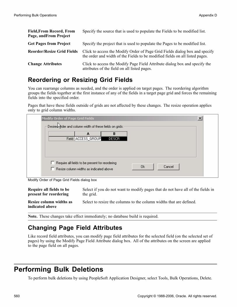
Performing Bulk Operations Appendix D
Field,From Record, FromPage, andFrom Project
Specify the source that is used to populate the Fields to be modified list.
Get Pages from Project Specify the project that is used to populate the Pages to be modified list.
Reorder/Resize Grid Fields Click to access the Modify Order of Page Grid Fields dialog box and specifythe order and width of the Fields to be modified fields on all listed pages.
Change Attributes Click to access the Modify Page Field Attribute dialog box and specify theattributes of the field on all listed pages.
Reordering or Resizing Grid FieldsYou can rearrange columns as needed, and the order is applied on target pages. The reordering algorithmgroups the fields together at the first instance of any of the fields in a target page grid and forces the remainingfields into the specified order.
Pages that have these fields outside of grids are not affected by these changes. The resize operation appliesonly to grid column widths.
Modify Order of Page Grid Fields dialog box
Require all fields to bepresent for reordering
Select if you do not want to modify pages that do not have all of the fields inthe grid.
Resize column widths asindicated above
Select to resize the columns to the column widths that are defined.
Note. These changes take effect immediately; no database build is required.
Changing Page Field AttributesLike record field attributes, you can modify page field attributes for the selected field (on the selected set ofpages) by using the Modify Page Field Attribute dialog box. All of the attributes on the screen are appliedto the page field on all pages.
Performing Bulk DeletionsTo perform bulk deletions by using PeopleSoft Application Designer, select Tools, Bulk Operations, Delete.
560 Copyright © 1988-2006, Oracle. All rights reserved.

Appendix D Performing Bulk Operations
Use the delete operation to:
• Remove the field from a list of pages, regardless of where the field exists on the page or whether it is in a grid.
• Remove the field from the list of records.
This removes associated PeopleCode and modifies associated SQL either in the record or, if the record is asubrecord, in parent records.
If the field is in the SELECT clause of the SQL, the removal is straightforward. However, if the field isalso used in a WHERE clause, or if the field is the only item in the SELECT clause, the record is notmodified. Instead, it is inserted into a project called BLK_<SOURCEFIELDNAME> as noted in messagesin the status screen.
Note. A project with a targeted field in SQL statements should be examined by hand to delete the fieldas required from the associated SQL.
Deleting fields from records and pages does not remove the field definition itself and it does not remove thefield from other applications, such as Crystal Reports.
Note. Because performing this operation changes records, you must subsequently rebuild the database,because each application data table is based on the record definition.
Copyright © 1988-2006, Oracle. All rights reserved. 561

Performing Bulk Operations Appendix D
562 Copyright © 1988-2006, Oracle. All rights reserved.

APPENDIX E
Running PeopleTools Cross-Reference Reports
This chapter provides an overview of cross-reference reports and discusses how to run a sample Crystal report.
Understanding Cross-Reference ReportsBy using PeopleTools, you can create new applications by defining menus and pages that you use to enterdata and database tables. PeopleTools includes a variety of cross-reference reports (similar to blueprints) thatguide you through the definitions (such as menus, pages, and records) that are delivered with the system andthose that you create or adapt with PeopleTools.
PeopleTools cross-reference reports are predefined Crystal reports, not unlike the standard reports that aredelivered with the PeopleSoft application. Like other standard reports, you can identify cross-referencereports by the three-character prefix XRF. The reports provide several views of the application, ranging fromhigh-level lists of the windows, menus, and pages to the detailed database attributes of fields.
You should already be familiar with the types of definitions that are delivered with the PeopleSoft application,as well as with PeopleTools and relational databases.
The cross-reference reports include:
Report ID Description
Fields and Pages XRFFLPN Lists all fields in alphabetical order.It includes the names of all recordand page definitions in which thefields occur and lists the field longnames.
Fields and Records XRFRCFL Lists all fields in alphabetical orderby the associated record definitionname. It details the field long name,type, length, and formatting.
Records and Fields XRFFLRC Lists all fields in alphabetical order.It includes the field long name, type,length, and formatting, as well as thenames of all record definitions thatcontain the field.
Copyright © 1988-2006, Oracle. All rights reserved. 563

Running PeopleTools Cross-Reference Reports Appendix E
Report ID Description
Applications and Fields XRFAPFL Lists all menus, such as generaltables, in alphabetical order,including the fields in each menu.For each field, it lists the field name,type, length, and format, as well asall record and page definitions thatcontain the field (in the window).
Fields Referenced by PeopleCodePrograms
XRFFLPC Lists all PeopleCode programs inalphabetical order by the associatedrecord definition and field. Itincludes the types of fields thatare referenced in the PeopleCodeprogram.
Field Listing XRFIELDS Lists all fields in alphabetical order.It includes field type, length, format,long name, and short name.
Menu Listing XRFMENU Lists all menus in alphabetical order,including all page definitions in eachmenu. It includes the associatedsearch record definition name anddetail page definition name.
Page Listing XRFPAGE Lists all page definitions inalphabetical order.
PeopleCode Programs and FieldReferences
XRFPCFL Lists record definitions that containfields with PeopleCode programattributes. It includes the fieldname, as well as the associatedrecord definitions and fields thatare referenced in the PeopleCodeprogram.
Pages with PeopleCode XRFPNPC Lists all pages that contain fieldswith PeopleCode attributes. Foreach page, it includes the name ofthe record definitions that containthe field, as well as the field nameand type
564 Copyright © 1988-2006, Oracle. All rights reserved.

Appendix E Running PeopleTools Cross-Reference Reports
Report ID Description
Records and Pages XRFRCPN Lists all record definitions inalphabetical order. It includes themenu and page definitions thatare associated with each recorddefinition.
Window Listing XRFWIN Lists all application menu windowsin alphabetical order.
Note. In addition to standard cross-reference reports, if you are familiar with the PeopleSoft database, you cangenerate additional ad hoc reports to extract the exact combination of information that you need.
Running a Crystal ReportRun cross-reference reports on the Process Scheduler Request page.
The following example explains how to generate the Field Cross Reference (XRFIELDS) report.
Process Scheduler Request page
To create a Field Cross Reference report:
1. Select PeopleTools, Process Scheduler , System Process Requests.The Sample Processes search page appears.
2. Click Add a New Value.3. Enter CrystalClient for the run control ID.4. Click Add.5. Click Run.The Process Scheduler Request page appears.
Copyright © 1988-2006, Oracle. All rights reserved. 565

Running PeopleTools Cross-Reference Reports Appendix E
6. Select the Field Cross Reference, XRFIELDS, and Crystal by clicking the Select check box next to each ofthese values in the Process List grid.
7. Click OK to generate a formatted display of this Crystal report in HTML.
566 Copyright © 1988-2006, Oracle. All rights reserved.
APPENDIX F
Working With Records Used in the MobileSynchronization Framework
This appendix provides an overview of records used in the Mobile Synchronization Framework and discusses how to:
• Configure records for the Mobile Synchronization Framework.• Example: Build records for the Mobile Synchronization Framework.
Note. PeopleSoft may support the Mobile Synchronization Framework in a future release.
Understanding Mobile Synchronization Framework RecordsBecause of the nature of the architecture of the Mobile Synchronization Framework, there are additionalsettings that need to be considered when building applications that you intend to run on mobile or disconnectedcomputers. These settings address the issue of the application database running on the main network beingupdated while mobile users have their computers in a disconnected state.
With the Mobile Synchronization Framework, the mobile user has a copy of the application tables runningon their computers. If a system administrator, for example, adds a column to a table used in the mobileapplication, the copy of this same table running on the disconnected computer is no longer current. When themobile users connect to the main network and attempt to synchronize the data on their machines with the datain the main application database, the synchronization operation will fail if the new column is a required (or’NOT NULL’) field, because the application database expects a value to be inserted within the new column.
To ensure that the synchronization operation completes successfully, the system allows default values tobe inserted in the new column.
Note. Default values can only be specified in fields of the following types: Character, Number, and SignedNumber.
Configuring Records for the Mobile SynchronizationFramework
This section discusses how to:
• Set record properties.• Set record field properties.
Copyright © 1988-2006, Oracle. All rights reserved. 567
Working With Records Used in the Mobile Synchronization Framework Appendix F
Setting Record PropertiesOn the Use tab of the Record Properties dialog there is a group box named Sync type (MSF) devoted entirelyto records used in mobile applications. The options in the Sync type (MSF) group box enable you to identifyrecords as being used for mobile applications by selecting either of the options.
Server —> User (DownSync)
Select this option if the data existing on the mobile computer needs tobe updated with the data existing on the main application database server.Selecting this option does not affect any behavior of the build process, such asinserting default values for required fields.
User —> Server (Up Sync) Select this option if the data existing on the main application database serverneeds to be updated by the data existing on the mobile computer.If this option is selected, and a Character, Number, or Signed Number columnis set as required, during the build process the system automatically insertsthe default values for these fields.Also, if this option is selected, the system does not allow you to set thefollowing field types as required fields:
• Long Character
• Date• Time• Datetime
Note. You can select both options, depending on the application requirements.
See AlsoChapter 6, “Creating Record Definitions,” Setting Record Properties, page 115
Working with Required Fields and Default ValuesThis section discusses how to:
• Create a required field.• Specify default values for required fields.
Creating a Required FieldAs with any record definition, you specify that a field is required on the Edits tab of the Record FieldProperties. Selecting the Required check box specifies that a particular field is ’NOT NULL’.
This is also the case with records used in mobile applications, except for records that have the User —> Server(Up Sync) option set. If set, only Character, Number, and Signed Number fields can be set to required. For allother field types, the system disables the Required check box.
Specifying Default Values for Required FieldsIf the User —> Server (Up Sync) option is set in the record properties, and the Required option is set in therecord field properties, during the build process the system inserts the following default values.
568 Copyright © 1988-2006, Oracle. All rights reserved.
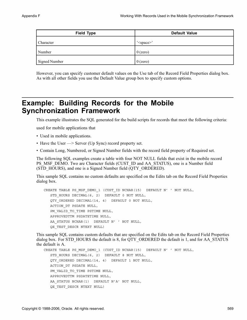
Appendix F Working With Records Used in the Mobile Synchronization Framework
Field Type Default Value
Character ’<space>’
Number 0 (zero)
Signed Number 0 (zero)
However, you can specify customer default values on the Use tab of the Record Field Properties dialog box.As with all other fields you use the Default Value group box to specify custom options.
Example: Building Records for the MobileSynchronization Framework
This example illustrates the SQL generated for the build scripts for records that meet the following criteria:
used for mobile applications that
• Used in mobile applications.• Have the User —> Server (Up Sync) record property set.• Contain Long, Numbered, or Signed Number fields with the record field property of Required set.
The following SQL examples create a table with four NOT NULL fields that exist in the mobile recordPS_MSF_DEMO. Two are Character fields (CUST_ID and AA_STATUS), one is a Number field(STD_HOURS), and one is a Signed Number field (QTY_ORDERED).
This sample SQL contains no custom defaults are specified on the Edits tab on the Record Field Propertiesdialog box.
CREATE TABLE PS_MSF_DEMO_1 (CUST_ID NCHAR(15) DEFAULT N’ ’ NOT NULL,
STD_HOURS DECIMAL(6, 2) DEFAULT 0 NOT NULL,
QTY_ORDERED DECIMAL(14, 4) DEFAULT 0 NOT NULL,
ACTION_DT PSDATE NULL,
PM_VALID_TO_TIME PSTIME NULL,
APPROVEDTTM PSDATETIME NULL,
AA_STATUS NCHAR(1) DEFAULT N’ ’ NOT NULL,
QE_TEST_DESCR NTEXT NULL)
This sample SQL contains custom defaults that are specified on the Edits tab on the Record Field Propertiesdialog box. For STD_HOURS the default is 8, for QTY_ORDERED the default is 1, and for AA_STATUSthe default is A.
CREATE TABLE PS_MSF_DEMO_1 (CUST_ID NCHAR(15) DEFAULT N’ ’ NOT NULL,
STD_HOURS DECIMAL(6, 2) DEFAULT 8 NOT NULL,
QTY_ORDERED DECIMAL(14, 4) DEFAULT 1 NOT NULL,
ACTION_DT PSDATE NULL,
PM_VALID_TO_TIME PSTIME NULL,
APPROVEDTTM PSDATETIME NULL,
AA_STATUS NCHAR(1) DEFAULT N’A’ NOT NULL,
QE_TEST_DESCR NTEXT NULL)
Copyright © 1988-2006, Oracle. All rights reserved. 569

Working With Records Used in the Mobile Synchronization Framework Appendix F
570 Copyright © 1988-2006, Oracle. All rights reserved.

Glossary of PeopleSoft Enterprise Terms
absence entitlement This element defines rules for granting paid time off for valid absences, such as sicktime, vacation, and maternity leave. An absence entitlement element defines theentitlement amount, frequency, and entitlement period.
absence take This element defines the conditions that must be met before a payee is entitledto take paid time off.
academic career In PeopleSoft Enterprise Campus Solutions, all course work that a student undertakesat an academic institution and that is grouped in a single student record. For example,a university that has an undergraduate school, a graduate school, and variousprofessional schools might define several academic careers—an undergraduate career,a graduate career, and separate careers for each professional school (law school,medical school, dental school, and so on).
academic institution In PeopleSoft Enterprise Campus Solutions, an entity (such as a university or college)that is independent of other similar entities and that has its own set of rules andbusiness processes.
academic organization In PeopleSoft Enterprise Campus Solutions, an entity that is part of the administrativestructure within an academic institution. At the lowest level, an academic organizationmight be an academic department. At the highest level, an academic organization canrepresent a division.
academic plan In PeopleSoft Enterprise Campus Solutions, an area of study—such as a major, minor,or specialization—that exists within an academic program or academic career.
academic program In PeopleSoft Enterprise Campus Solutions, the entity to which a student applies and isadmitted and from which the student graduates.
accounting class In PeopleSoft Enterprise Performance Management, the accounting class defines howa resource is treated for generally accepted accounting practices. The Inventoryclass indicates whether a resource becomes part of a balance sheet account, such asinventory or fixed assets, while the Non-inventory class indicates that the resource istreated as an expense of the period during which it occurs.
accounting date The accounting date indicates when a transaction is recognized, as opposed to the datethe transaction actually occurred. The accounting date and transaction date can be thesame. The accounting date determines the period in the general ledger to which thetransaction is to be posted. You can only select an accounting date that falls within anopen period in the ledger to which you are posting. The accounting date for an itemis normally the invoice date.
accounting split The accounting split method indicates how expenses are allocated or divided amongone or more sets of accounting ChartFields.
accumulator You use an accumulator to store cumulative values of defined items as they areprocessed. You can accumulate a single value over time or multiple values overtime. For example, an accumulator could consist of all voluntary deductions, or allcompany deductions, enabling you to accumulate amounts. It allows total flexibilityfor time periods and values accumulated.
action reason The reason an employee’s job or employment information is updated. The actionreason is entered in two parts: a personnel action, such as a promotion, termination, orchange from one pay group to another—and a reason for that action. Action reasonsare used by PeopleSoft Enterprise Human Resources, PeopleSoft Enterprise Benefits
Copyright © 1988-2006, Oracle. All rights reserved. 571
Glossary
Administration, PeopleSoft Enterprise Stock Administration, and the COBRAAdministration feature of the Base Benefits business process.
action template In PeopleSoft Enterprise Receivables, outlines a set of escalating actions that thesystem or user performs based on the period of time that a customer or item has been inan action plan for a specific condition.
activity In PeopleSoft Enterprise LearningManagement, an instance of a catalog item(sometimes called a class) that is available for enrollment. The activity definessuch things as the costs that are associated with the offering, enrollment limits anddeadlines, and waitlisting capacities.
In PeopleSoft Enterprise Performance Management, the work of an organization andthe aggregation of actions that are used for activity-based costing.
In PeopleSoft Enterprise Project Costing, the unit of work that provides a furtherbreakdown of projects—usually into specific tasks.
In PeopleSoft Workflow, a specific transaction that you might need to perform in abusiness process. Because it consists of the steps that are used to perform a transaction,it is also known as a step map.
address usage In PeopleSoft Enterprise Campus Solutions, a grouping of address types defining theorder in which the address types are used. For example, you might define an addressusage code to process addresses in the following order: billing address, dormitoryaddress, home address, and then work address.
adjustment calendar In PeopleSoft Enterprise Campus Solutions, the adjustment calendar controls how aparticular charge is adjusted on a student’s account when the student drops classesor withdraws from a term. The charge adjustment is based on how much time haselapsed from a predetermined date, and it is determined as a percentage of the originalcharge amount.
administrative function In PeopleSoft Enterprise Campus Solutions, a particular functional area that processeschecklists, communication, and comments. The administrative function identifieswhich variable data is added to a person’s checklist or communication record when aspecific checklist code, communication category, or comment is assigned to thestudent. This key data enables you to trace that checklist, communication, or commentback to a specific processing event in a functional area.
admit type In PeopleSoft Enterprise Campus Solutions, a designation used to distinguishfirst-year applications from transfer applications.
agreement In PeopleSoft Enterprise eSettlements, provides a way to group and specify processingoptions, such as payment terms, pay from a bank, and notifications by a buyer andsupplier location combination.
allocation rule In PeopleSoft Enterprise Incentive Management, an expression within compensationplans that enables the system to assign transactions to nodes and participants. Duringtransaction allocation, the allocation engine traverses the compensation structurefrom the current node to the root node, checking each node for plans that containallocation rules.
alternate account A feature in PeopleSoft Enterprise General Ledger that enables you to createa statutory chart of accounts and enter statutory account transactions at thedetail transaction level, as required for recording and reporting by some nationalgovernments.
analysis database In PeopleSoft Enterprise Campus Solutions, database tables that store large amountsof student information that may not appear in standard report formats. The analysisdatabase tables contain keys for all objects in a report that an application program canuse to reference other student-record objects that are not contained in the printedreport. For instance, the analysis database contains data on courses that are considered
572 Copyright © 1988-2006, Oracle. All rights reserved.

Glossary
for satisfying a requirement but that are rejected. It also contains information oncourses captured by global limits. An analysis database is used in PeopleSoftEnterprise Academic Advisement.
ApplicationMessaging PeopleSoft Application Messaging enables applications within the PeopleSoftEnterprise product family to communicate synchronously or asynchronously withother PeopleSoft Enterprise and third-party applications. An application messagedefines the records and fields to be published or subscribed to.
AR specialist Abbreviation for receivables specialist. In PeopleSoft Enterprise Receivables, anindividual in who tracks and resolves deductions and disputed items.
arbitration plan In PeopleSoft Enterprise Pricer, defines how price rules are to be applied to the baseprice when the transaction is priced.
assessment rule In PeopleSoft Enterprise Receivables, a user-defined rule that the system uses toevaluate the condition of a customer’s account or of individual items to determinewhether to generate a follow-up action.
asset class An asset group used for reporting purposes. It can be used in conjunction with the assetcategory to refine asset classification.
attribute/value pair In PeopleSoft Enterprise Directory Interface, relates the data that makes up an entry inthe directory information tree.
audience In PeopleSoft Enterprise Campus Solutions, a segment of the database that relatesto an initiative, or a membership organization that is based on constituent attributesrather than a dues-paying structure. Examples of audiences include the Class of ’65and Undergraduate Arts & Sciences.
authentication server A server that is set up to verify users of the system.
base time period In PeopleSoft Enterprise Business Planning, the lowest level time period in a calendar.
benchmark job In PeopleSoft Enterprise Workforce Analytics Solution, a benchmark job is a jobcode for which there is corresponding salary survey data from published, third-partysources.
billing career In PeopleSoft Enterprise Campus Solutions, the one career under which other careersare grouped for billing purposes if a student is active simultaneously in multiplecareers.
bio bit or bio brief In PeopleSoft Enterprise Campus Solutions, a report that summarizes informationstored in the system about a particular constituent. You can generate standard orspecialized reports.
book In PeopleSoft Enterprise Asset Management, used for storing financial and taxinformation, such as costs, depreciation attributes, and retirement informationon assets.
branch A tree node that rolls up to nodes above it in the hierarchy, as defined in PeopleSoftTree Manager.
budgetary account only An account used by the system only and not by users; this type of account doesnot accept transactions. You can only budget with this account. Formerly called“system-maintained account.”
budget check In commitment control, the processing of source transactions against control budgetledgers, to see if they pass, fail, or pass with a warning.
budget control In commitment control, budget control ensures that commitments and expendituresdon’t exceed budgets. It enables you to track transactions against correspondingbudgets and terminate a document’s cycle if the defined budget conditions are not met.
Copyright © 1988-2006, Oracle. All rights reserved. 573

Glossary
For example, you can prevent a purchase order from being dispatched to a vendor ifthere are insufficient funds in the related budget to support it.
budget period The interval of time (such as 12 months or 4 quarters) into which a period is dividedfor budgetary and reporting purposes. The ChartField allows maximum flexibility todefine operational accounting time periods without restriction to only one calendar.
business activity The name of a subset of a detailed business process. This might be a specifictransaction, task, or action that you perform in a business process.
business event In PeopleSoft Enterprise Receivables, defines the processing characteristics for theReceivable Update process for a draft activity.
In PeopleSoft Enterprise Sales Incentive Management, an original business transactionor activity that may justify the creation of a PeopleSoft Enterprise IncentiveManagement event (a sale, for example).
business process A standard set of 17 business processes are defined and maintained by the PeopleSoftEnterprise product families and are supported by the Business Process Engineeringgroup. An example of a business process is Order Fulfillment, which is a businessprocess that manages sales orders and contracts, inventory, billing, and so forth.
See also detailed business process.
business task The name of the specific function depicted in one of the business processes.
business unit A corporation or a subset of a corporation that is independent with regard to one ormore operational or accounting functions.
buyer In PeopleSoft Enterprise eSettlements, an organization (or business unit, as opposedto an individual) that transacts with suppliers (vendors) within the system. A buyercreates payments for purchases that are made in the system.
campus In PeopleSoft Enterprise Campus Solutions, an entity that is usually associated witha distinct physical administrative unit, that belongs to a single academic institution,that uses a unique course catalog, and that produces a common transcript for studentswithin the same academic career.
catalog item In PeopleSoft Enterprise LearningManagement, a specific topic that a learner canstudy and have tracked. For example, “Introduction to Microsoft Word.” A catalogitem contains general information about the topic and includes a course code,description, categorization, keywords, and delivery methods. A catalog item canhave one or more learning activities.
catalog map In PeopleSoft Enterprise Catalog Management, translates values from the catalogsource data to the format of the company’s catalog.
catalog partner In PeopleSoft Enterprise Catalog Management, shares responsibility with theenterprise catalog manager for maintaining catalog content.
categorization Associates partner offerings with catalog offerings and groups them into enterprisecatalog categories.
category In PeopleSoft Enterprise Campus Solutions, a broad grouping to which specificcomments or communications (contexts) are assigned. Category codes are also linkedto 3C access groups so that you can assign data-entry or view-only privileges acrossfunctions.
channel In PeopleSoft MultiChannel Framework, email, chat, voice (computer telephoneintegration [CTI]), or a generic event.
ChartField A field that stores a chart of accounts, resources, and so on, depending on thePeopleSoft Enterprise application. ChartField values represent individual accountnumbers, department codes, and so forth.
574 Copyright © 1988-2006, Oracle. All rights reserved.
Glossary
ChartField balancing You can require specific ChartFields to match up (balance) on the debit and the creditside of a transaction.
ChartField combination edit The process of editing journal lines for valid ChartField combinations based onuser-defined rules.
ChartKey One or more fields that uniquely identify each row in a table. Some tables contain onlyone field as the key, while others require a combination.
checkbook In PeopleSoft Enterprise Promotions Management, enables you to view financial data(such as planned, incurred, and actual amounts) that is related to funds and tradepromotions.
checklist code In PeopleSoft Enterprise Campus Solutions, a code that represents a list of plannedor completed action items that can be assigned to a staff member, volunteer, or unit.Checklists enable you to view all action assignments on one page.
class In PeopleSoft Enterprise Campus Solutions, a specific offering of a course componentwithin an academic term.
See also course.
Class ChartField A ChartField value that identifies a unique appropriation budget key when youcombine it with a fund, department ID, and program code, as well as a budget period.Formerly called sub-classification.
clearance In PeopleSoft Enterprise Campus Solutions, the period of time during whicha constituent in PeopleSoft Enterprise Contributor Relations is approved forinvolvement in an initiative or an action. Clearances are used to prevent developmentofficers from making multiple requests to a constituent during the same time period.
clone In PeopleCode, to make a unique copy. In contrast, to copymay mean making anew reference to an object, so if the underlying object is changed, both the copy andthe original change.
cohort In PeopleSoft Enterprise Campus Solutions, the highest level of the three-levelclassification structure that you define for enrollment management. You can define acohort level, link it to other levels, and set enrollment target numbers for it.
See also population and division.
collection To make a set of documents available for searching in Verity, you must first createat least one collection. A collection is set of directories and files that allow searchapplication users to use the Verity search engine to quickly find and display sourcedocuments that match search criteria. A collection is a set of statistics and pointersto the source documents, stored in a proprietary format on a file server. Because acollection can only store information for a single location, PeopleTools maintains a setof collections (one per language code) for each search index object.
collection rule In PeopleSoft Enterprise Receivables, a user-defined rule that defines actions totake for a customer based on both the amount and the number of days past due foroutstanding balances.
comm key See communication key.
communication key In PeopleSoft Enterprise Campus Solutions, a single code for entering a combinationof communication category, communication context, communication method,communication direction, and standard letter code. Communication keys (also calledcomm keys or speed keys) can be created for background processes as well as forspecific users.
Copyright © 1988-2006, Oracle. All rights reserved. 575

Glossary
compensation object In PeopleSoft Enterprise Incentive Management, a node within a compensationstructure. Compensation objects are the building blocks that make up a compensationstructure’s hierarchical representation.
compensation structure In PeopleSoft Enterprise Incentive Management, a hierarchical relationship ofcompensation objects that represents the compensation-related relationship betweenthe objects.
component interface A component interface is a set of application programming interfaces (APIs) that youcan use to access and modify PeopleSoft Enterprise database information using aprogram instead of the PeopleSoft client.
condition In PeopleSoft Enterprise Receivables, occurs when there is a change of status for acustomer’s account, such as reaching a credit limit or exceeding a user-defined balancedue.
configuration parametercatalog
Used to configure an external system with PeopleSoft Enterprise. For example, aconfiguration parameter catalog might set up configuration and communicationparameters for an external server.
configuration plan In PeopleSoft Enterprise Incentive Management, configuration plans hold allocationinformation for common variables (not incentive rules) and are attached to a nodewithout a participant. Configuration plans are not processed by transactions.
constituents In PeopleSoft Enterprise Campus Solutions, friends, alumni, organizations,foundations, or other entities affiliated with the institution, and about which theinstitution maintains information. The constituent types delivered with PeopleSoftEnterprise Contributor Relations Solutions are based on those defined by the Councilfor the Advancement and Support of Education (CASE).
content reference Content references are pointers to content registered in the portal registry. These aretypically either URLs or iScripts. Content references fall into three categories: targetcontent, templates, and template pagelets.
context In PeopleCode, determines which buffer fields can be contextually referenced andwhich is the current row of data on each scroll level when a PeopleCode programis running.
In PeopleSoft Enterprise Campus Solutions, a specific instance of a comment orcommunication. One or more contexts are assigned to a category, which you link to3C access groups so that you can assign data-entry or view-only privileges acrossfunctions.
In PeopleSoft Enterprise Incentive Management, a mechanism that is used todetermine the scope of a processing run. PeopleSoft Enterprise Incentive Managementuses three types of context: plan, period, and run-level.
control table Stores information that controls the processing of an application. This type ofprocessing might be consistent throughout an organization, or it might be used only byportions of the organization for more limited sharing of data.
cost-plus contract line A rate-based contract line associated with a fee component of Award, Fixed, Incentive,or Other. Rate-based contract lines associated with a fee type of None are notconsidered cost-plus contract lines.
cost profile A combination of a receipt cost method, a cost flow, and a deplete cost method. Aprofile is associated with a cost book and determines how items in that book arevalued, as well as how the material movement of the item is valued for the book.
cost row A cost transaction and amount for a set of ChartFields.
course In PeopleSoft Enterprise Campus Solutions, a course that is offered by a school andthat is typically described in a course catalog. A course has a standard syllabus and
576 Copyright © 1988-2006, Oracle. All rights reserved.
Glossary
credit level; however, these may be modified at the class level. Courses can containmultiple components such as lecture, discussion, and lab.
See also class.
course share set In PeopleSoft Enterprise Campus Solutions, a tag that defines a set of requirementgroups that can share courses. Course share sets are used in PeopleSoft EnterpriseAcademic Advisement.
current learning In PeopleSoft Enterprise LearningManagement, a self-service repository for all of alearner’s in-progress learning activities and programs.
data acquisition In PeopleSoft Enterprise Incentive Management, the process during which rawbusiness transactions are acquired from external source systems and fed into theoperational data store (ODS).
data cube In PeopleSoft Analytic Calculation Engine, a data cube is a container for one kindof data (such as Sales data) and works with in tandem with one or more dimensions.Dimensions and data cubes in PeopleSoft Analytic Calculation Engine are unrelatedto dimensions and online analytical processing (OLAP) cubes in PeopleSoft CubeManager.
data elements Data elements, at their simplest level, define a subset of data and the rules by whichto group them.
For Workforce Analytics, data elements are rules that tell the system what measures toretrieve about your workforce groups.
dataset A data grouping that enables role-based filtering and distribution of data. You canlimit the range and quantity of data that is displayed for a user by associating datasetrules with user roles. The result of dataset rules is a set of data that is appropriatefor the user’s roles.
delivery method In PeopleSoft Enterprise LearningManagement, identifies the primary type ofdelivery method in which a particular learning activity is offered. Also providesdefault values for the learning activity, such as cost and language. This is primarilyused to help learners search the catalog for the type of delivery from which they learnbest. Because PeopleSoft Enterprise LearningManagement is a blended learningsystem, it does not enforce the delivery method.
In PeopleSoft Enterprise Supply Chain Management, identifies the method by whichgoods are shipped to their destinations (such as truck, air, and rail). The deliverymethod is specified when creating shipment schedules.
delivery method type In PeopleSoft Enterprise LearningManagement, identifies how learning activities canbe delivered—for example, through online learning, classroom instruction, seminars,books, and so forth—in an organization. The type determines whether the deliverymethod includes scheduled components.
detailed business process A subset of the business process. For example, the detailed business process namedDetermine Cash Position is a subset of the business process called Cash Management.
dimension In PeopleSoft Analytic Calculation Engine, a dimension contains a list of one kindof data that can span various contexts, and it is a basic component of an analyticmodel. Within the analytic model, a dimension is attached to one or more data cubes.In PeopleSoft Cube Manager, a dimension is the most basic component of an OLAPcube and specifies the PeopleSoft metadata to be used to create the dimension’s rollupstructure. Dimensions and data cubes in PeopleSoft Analytic Calculation Engine areunrelated to dimensions and OLAP cubes in PeopleSoft Cube Manager.
directory information tree In PeopleSoft Enterprise Directory Interface, the representation of a directory’shierarchical structure.
Copyright © 1988-2006, Oracle. All rights reserved. 577

Glossary
division In PeopleSoft Enterprise Campus Solutions, the lowest level of the three-levelclassification structure that you define in PeopleSoft Enterprise Recruiting andAdmissions for enrollment management. You can define a division level, link it toother levels, and set enrollment target numbers for it.
See also population and cohort.
document sequencing A flexible method that sequentially numbers the financial transactions (for example,bills, purchase orders, invoices, and payments) in the system for statutory reportingand for tracking commercial transaction activity.
dynamic detail tree A tree that takes its detail values—dynamic details—directly from a table in thedatabase, rather than from a range of values that are entered by the user.
edit table A table in the database that has its own record definition, such as the Department table.As fields are entered into a PeopleSoft Enterprise application, they can be validatedagainst an edit table to ensure data integrity throughout the system.
effective date Amethod of dating information in PeopleSoft Enterprise applications. You canpredate information to add historical data to your system, or postdate information inorder to enter it before it actually goes into effect. By using effective dates, you don’tdelete values; you enter a new value with a current effective date.
EIM ledger Abbreviation for Enterprise Incentive Management ledger. In PeopleSoft EnterpriseIncentive Management, an object to handle incremental result gathering within thescope of a participant. The ledger captures a result set with all of the appropriate tracesto the data origin and to the processing steps of which it is a result.
elimination set In PeopleSoft Enterprise General Ledger, a related group of intercompany accountsthat is processed during consolidations.
entry event In PeopleSoft Enterprise General Ledger, Receivables, Payables, Purchasing, andBilling, a business process that generates multiple debits and credits resulting fromsingle transactions to produce standard, supplemental accounting entries.
equitization In PeopleSoft Enterprise General Ledger, a business process that enables parentcompanies to calculate the net income of subsidiaries on a monthly basis and adjustthat amount to increase the investment amount and equity income amount beforeperforming consolidations.
equity item limit In PeopleSoft Enterprise Campus Solutions, the amounts of funds set by the institutionto be awarded with discretionary or gift funds. The limit could be reduced by amountsequal to such things as expected family contribution (EFC) or parent contribution.Students are packaged by Equity Item Type Groups and Related Equity Item Types.This limit can be used to assure that similar student populations are packaged equally.
event A predefined point either in the Component Processor flow or in the program flow.As each point is encountered, the event activates each component, triggering anyPeopleCode program that is associated with that component and that event. Examplesof events are FieldChange, SavePreChange, and RowDelete.
In PeopleSoft Enterprise Human Resources, also refers to an incident that affectsbenefits eligibility.
event propagation process In PeopleSoft Enterprise Sales Incentive Management, a process that determines,through logic, the propagation of an original PeopleSoft Enterprise IncentiveManagement event and creates a derivative (duplicate) of the original event tobe processed by other objects. PeopleSoft Enterprise Enterprise Sales IncentiveManagement uses this mechanism to implement splits, roll-ups, and so on. Eventpropagation determines who receives the credit.
exception In PeopleSoft Enterprise Receivables, an item that either is a deduction or is in dispute.
578 Copyright © 1988-2006, Oracle. All rights reserved.

Glossary
exclusive pricing In PeopleSoft Enterprise Order Management, a type of arbitration plan that isassociated with a price rule. Exclusive pricing is used to price sales order transactions.
fact In PeopleSoft Enterprise applications, facts are numeric data values from fields from asource database as well as an analytic application. A fact can be anything you wantto measure your business by, for example, revenue, actual, budget data, or salesnumbers. A fact is stored on a fact table.
financial aid term In PeopleSoft Enterprise Campus Solutions, a combination of a period of time that theschool determines as an instructional accounting period and an academic career. Itis created and defined during the setup process. Only terms eligible for financial aidare set up for each financial aid career.
forecast item A logical entity with a unique set of descriptive demand and forecast data that is usedas the basis to forecast demand. You create forecast items for a wide range of uses, butthey ultimately represent things that you buy, sell, or use in your organization and forwhich you require a predictable usage.
fund In PeopleSoft Enterprise Promotions Management, a budget that can be used to fundpromotional activity. There are four funding methods: top down, fixed accrual,rolling accrual, and zero-based accrual.
gap In PeopleSoft Enterprise Campus Solutions, an artificial figure that sets aside anamount of unmet financial aid need that is not funded with Title IV funds. A gap canbe used to prevent fully funding any student to conserve funds, or it can be used topreserve unmet financial aid need so that institutional funds can be awarded.
generic process type In PeopleSoft Process Scheduler, process types are identified by a generic processtype. For example, the generic process type SQR includes all SQR process types,such as SQR process and SQR report.
gift table In PeopleSoft Enterprise Campus Solutions, a table or so-called donor pyramiddescribing the number and size of gifts that you expect will be needed to successfullycomplete the campaign in PeopleSoft Enterprise Contributor Relations. The gift tableenables you to estimate the number of donors and prospects that you need at eachgift level to reach the campaign goal.
GL business unit Abbreviation for general ledger business unit. A unit in an organization that is anindependent entity for accounting purposes. It maintains its own set of accountingbooks.
See also business unit.
GL entry template Abbreviation for general ledger entry template. In PeopleSoft Enterprise CampusSolutions, a template that defines how a particular item is sent to the general ledger.An item-type maps to the general ledger, and the GL entry template can involvemultiple general ledger accounts. The entry to the general ledger is further controlledby high-level flags that control the summarization and the type of accounting—that is,accrual or cash.
GL Interface process Abbreviation forGeneral Ledger Interface process. In PeopleSoft Enterprise CampusSolutions, a process that is used to send transactions from PeopleSoft EnterpriseStudent Financials to the general ledger. Item types are mapped to specific generalledger accounts, enabling transactions to move to the general ledger when the GLInterface process is run.
group In PeopleSoft Enterprise Billing and Receivables, a posting entity that comprises oneor more transactions (items, deposits, payments, transfers, matches, or write-offs).
In PeopleSoft Enterprise Human Resources Management and Supply ChainManagement, any set of records that are associated under a single name or variable to
Copyright © 1988-2006, Oracle. All rights reserved. 579

Glossary
run calculations in PeopleSoft business processes. In PeopleSoft Enterprise Time andLabor, for example, employees are placed in groups for time reporting purposes.
incentive object In PeopleSoft Enterprise Incentive Management, the incentive-related objects thatdefine and support the PeopleSoft Enterprise Incentive Management calculationprocess and results, such as plan templates, plans, results data, and user interactionobjects.
incentive rule In PeopleSoft Enterprise Sales Incentive Management, the commands that act ontransactions and turn them into compensation. A rule is one part in the process ofturning a transaction into compensation.
incur In PeopleSoft Enterprise Promotions Management, to become liable for a promotionalpayment. In other words, you owe that amount to a customer for promotionalactivities.
initiative In PeopleSoft Enterprise Campus Solutions, the basis from which all advancementplans are executed. It is an organized effort targeting a specific constituency, and it canoccur over a specified period of time with specific purposes and goals. An initiativecan be a campaign, an event, an organized volunteer effort, a membership drive, orany other type of effort defined by the institution. Initiatives can be multipart, andthey can be related to other initiatives. This enables you to track individual parts of aninitiative, as well as entire initiatives.
inquiry access In PeopleSoft Enterprise Campus Solutions, a type of security access that permits theuser only to view data.
See also update access.
institution In PeopleSoft Enterprise Campus Solutions, an entity (such as a university or college)that is independent of other similar entities and that has its own set of rules andbusiness processes.
integration A relationship between two compatible integration points that enables communicationto take place between systems. Integrations enable PeopleSoft Enterprise applicationsto work seamlessly with other PeopleSoft Enterprise applications or with third-partysystems or software.
integration point An interface that a system uses to communicate with another PeopleSoft Enterpriseapplication or an external application.
integration set A logical grouping of integrations that applications use for the same business purpose.For example, the integration set ADVANCED_SHIPPING_ORDER contains all of theintegrations that notify a customer that an order has shipped.
item In PeopleSoft Enterprise Inventory, a tangible commodity that is stored in a businessunit (shipped from a warehouse).
In PeopleSoft Enterprise Demand Planning, Inventory Policy Planning, and SupplyPlanning, a noninventory item that is designated as being used for planning purposesonly. It can represent a family or group of inventory items. It can have a planning billof material (BOM) or planning routing, and it can exist as a component on a planningBOM. A planning item cannot be specified on a production or engineering BOM orrouting, and it cannot be used as a component in a production. The quantity on handwill never be maintained.
In PeopleSoft Enterprise Receivables, an individual receivable. An item can be aninvoice, a credit memo, a debit memo, a write-off, or an adjustment.
item shuffle In PeopleSoft Enterprise Campus Solutions, a process that enables you to change apayment allocation without having to reverse the payment.
580 Copyright © 1988-2006, Oracle. All rights reserved.
Glossary
joint communication In PeopleSoft Enterprise Campus Solutions, one letter that is addressed jointly to twopeople. For example, a letter might be addressed to both Mr. Sudhir Awat and Ms.Samantha Mortelli. A relationship must be established between the two individuals inthe database, and at least one of the individuals must have an ID in the database.
keyword In PeopleSoft Enterprise Campus Solutions, a term that you link to particular elementswithin PeopleSoft Enterprise Student Financials, Financial Aid, and ContributorRelations. You can use keywords as search criteria that enable you to locate specificrecords in a search dialog box.
KPI An abbreviation for key performance indicator. A high-level measurement of how wellan organization is doing in achieving critical success factors. This defines the datavalue or calculation upon which an assessment is determined.
LDIF file Abbreviation for Lightweight Directory Access Protocol (LDAP) Data InterchangeFormat file. Contains discrepancies between PeopleSoft Enterprise data and directorydata.
learner group In PeopleSoft Enterprise LearningManagement, a group of learners who are linkedto the same learning environment. Members of the learner group can share the sameattributes, such as the same department or job code. Learner groups are used to controlaccess to and enrollment in learning activities and programs. They are also used toperform group enrollments and mass enrollments in the back office.
learning components In PeopleSoft Enterprise LearningManagement, the foundational building blocksof learning activities. PeopleSoft Enterprise Learning Management supports sixbasic types of learning components: web-based, session, webcast, test, survey, andassignment. One or more of these learning component types compose a singlelearning activity.
learning environment In PeopleSoft Enterprise LearningManagement, identifies a set of categories andcatalog items that can be made available to learner groups. Also defines the defaultvalues that are assigned to the learning activities and programs that are created within aparticular learning environment. Learning environments provide a way to partition thecatalog so that learners see only those items that are relevant to them.
learning history In PeopleSoft Enterprise LearningManagement, a self-service repository for all of alearner’s completed learning activities and programs.
ledger mapping You use ledger mapping to relate expense data from general ledger accounts toresource objects. Multiple ledger line items can be mapped to one or more resourceIDs. You can also use ledger mapping to map dollar amounts (referred to as rates)to business units. You can map the amounts in two different ways: an actual amountthat represents actual costs of the accounting period, or a budgeted amount that can beused to calculate the capacity rates as well as budgeted model results. In PeopleSoftEnterprise Warehouse, you can map general ledger accounts to the EW Ledger table.
library section In PeopleSoft Enterprise Incentive Management, a section that is defined in a plan (ortemplate) and that is available for other plans to share. Changes to a library section arereflected in all plans that use it.
linked section In PeopleSoft Enterprise Incentive Management, a section that is defined in a plantemplate but appears in a plan. Changes to linked sections propagate to plans usingthat section.
linked variable In PeopleSoft Enterprise Incentive Management, a variable that is defined andmaintained in a plan template and that also appears in a plan. Changes to linkedvariables propagate to plans using that variable.
LMS Abbreviation for learning management system. In PeopleSoft Enterprise CampusSolutions, LMS is a PeopleSoft Enterprise Student Records feature that provides a
Copyright © 1988-2006, Oracle. All rights reserved. 581

Glossary
common set of interoperability standards that enable the sharing of instructionalcontent and data between learning and administrative environments.
load In PeopleSoft Enterprise Inventory, identifies a group of goods that are shippedtogether. Load management is a feature of PeopleSoft Enterprise Inventory that is usedto track the weight, the volume, and the destination of a shipment.
local functionality In PeopleSoft Enterprise HRMS, the set of information that is available for a specificcountry. You can access this information when you click the appropriate country flagin the global window, or when you access it by a local country menu.
location Locations enable you to indicate the different types of addresses—for a company, forexample, one address to receive bills, another for shipping, a third for postal deliveries,and a separate street address. Each address has a different location number. Theprimary location—indicated by a 1—is the address you use most often and may bedifferent from the main address.
logistical task In PeopleSoft Enterprise Services Procurement, an administrative task that is related tohiring a service provider. Logistical tasks are linked to the service type on the workorder so that different types of services can have different logistical tasks. Logisticaltasks include both preapproval tasks (such as assigning a new badge or ordering anew laptop) and postapproval tasks (such as scheduling orientation or setting up theservice provider email). The logistical tasks can be mandatory or optional. Mandatorypreapproval tasks must be completed before the work order is approved. Mandatorypostapproval tasks, on the other hand, must be completed before a work order isreleased to a service provider.
market template In PeopleSoft Enterprise Incentive Management, additional functionality that isspecific to a given market or industry and is built on top of a product category.
mass change In PeopleSoft Enterprise Campus Solutions, mass change is a SQL generator that canbe used to create specialized functionality. Using mass change, you can set up aseries of Insert, Update, or Delete SQL statements to perform business functions thatare specific to the institution.
See also 3C engine.
match group In PeopleSoft Enterprise Receivables, a group of receivables items and matching offsetitems. The system creates match groups by using user-defined matching criteria forselected field values.
MCF server Abbreviation for PeopleSoft MultiChannel Framework server. Comprises theuniversal queue server and the MCF log server. Both processes are started whenMCFServers is selected in an application server domain configuration.
merchandising activity In PeopleSoft Enterprise Promotions Management, a specific discount type that isassociated with a trade promotion (such as off-invoice, billback or rebate, or lump-sumpayment) that defines the performance that is required to receive the discount. In theindustry, you may know this as an offer, a discount, a merchandising event, an event,or a tactic.
meta-SQL Meta-SQL constructs expand into platform-specific SQL substrings. They are used infunctions that pass SQL strings, such as in SQL objects, the SQLExec function, andPeopleSoft Application Engine programs.
metastring Metastrings are special expressions included in SQL string literals. The metastrings,prefixed with a percent (%) symbol, are included directly in the string literals. Theyexpand at run time into an appropriate substring for the current database platform.
multibook In PeopleSoft Enterprise General Ledger, multiple ledgers having multiple-basecurrencies that are defined for a business unit, with the option to post a single
582 Copyright © 1988-2006, Oracle. All rights reserved.

Glossary
transaction to all base currencies (all ledgers) or to only one of those base currencies(ledgers).
multicurrency The ability to process transactions in a currency other than the business unit’s basecurrency.
national allowance In PeopleSoft Enterprise Promotions Management, a promotion at the corporate levelthat is funded by nondiscretionary dollars. In the industry, you may know this as anational promotion, a corporate promotion, or a corporate discount.
need In PeopleSoft Enterprise Campus Solutions, the difference between the cost ofattendance (COA) and the expected family contribution (EFC). It is the gap betweenthe cost of attending the school and the student’s resources. The financial aid packageis based on the amount of financial need. The process of determining a student’sneed is called need analysis.
node-oriented tree A tree that is based on a detail structure, but the detail values are not used.
pagelet Each block of content on the home page is called a pagelet. These pagelets displaysummary information within a small rectangular area on the page. The pagelet provideusers with a snapshot of their most relevant PeopleSoft Enterprise and non-PeopleSoftEnterprise content.
participant In PeopleSoft Enterprise Incentive Management, participants are recipients of theincentive compensation calculation process.
participant object Each participant object may be related to one or more compensation objects.
See also compensation object.
partner A company that supplies products or services that are resold or purchased by theenterprise.
pay cycle In PeopleSoft Enterprise Payables, a set of rules that define the criteria by which itshould select scheduled payments for payment creation.
payment shuffle In PeopleSoft Enterprise Campus Solutions, a process allowing payments that havebeen previously posted to a student’s account to be automatically reapplied when ahigher priority payment is posted or the payment allocation definition is changed.
pending item In PeopleSoft Enterprise Receivables, an individual receivable (such as an invoice,a credit memo, or a write-off) that has been entered in or created by the system, buthasn’t been posted.
PeopleCode PeopleCode is a proprietary language, executed by the PeopleSoft Enterprisecomponent processor. PeopleCode generates results based on existing data or useractions. By using various tools provided with PeopleTools, external services areavailable to all PeopleSoft Enterprise applications wherever PeopleCode can beexecuted.
PeopleCode event See event.
PeopleSoft Pure InternetArchitecture
The fundamental architecture on which PeopleSoft 8 applications are constructed,consisting of a relational database management system (RDBMS), an applicationserver, a web server, and a browser.
performance measurement In PeopleSoft Enterprise Incentive Management, a variable used to store data (similarto an aggregator, but without a predefined formula) within the scope of an incentiveplan. Performance measures are associated with a plan calendar, territory, andparticipant. Performance measurements are used for quota calculation and reporting.
period context In PeopleSoft Enterprise Incentive Management, because a participant typicallyuses the same compensation plan for multiple periods, the period context associates
Copyright © 1988-2006, Oracle. All rights reserved. 583

Glossary
a plan context with a specific calendar period and fiscal year. The period contextreferences the associated plan context, thus forming a chain. Each plan context has acorresponding set of period contexts.
person of interest A person about whom the organization maintains information but who is not part ofthe workforce.
personal portfolio In PeopleSoft Enterprise Campus Solutions, the user-accessible menu item thatcontains an individual’s name, address, telephone number, and other personalinformation.
plan In PeopleSoft Enterprise Sales Incentive Management, a collection of allocation rules,variables, steps, sections, and incentive rules that instruct the PeopleSoft EnterpriseIncentive Management engine in how to process transactions.
plan context In PeopleSoft Enterprise Incentive Management, correlates a participant withthe compensation plan and node to which the participant is assigned, enablingthe PeopleSoft Enterprise Incentive Management system to find anything that isassociated with the node and that is required to perform compensation processing.Each participant, node, and plan combination represents a unique plan context—ifthree participants are on a compensation structure, each has a different plan context.Configuration plans are identified by plan contexts and are associated with theparticipants that refer to them.
plan template In PeopleSoft Enterprise Incentive Management, the base from which a plan is created.A plan template contains common sections and variables that are inherited by all plansthat are created from the template. A template may contain steps and sections thatare not visible in the plan definition.
planned learning In PeopleSoft Enterprise LearningManagement, a self-service repository for all ofa learner’s planned learning activities and programs.
planning instance In PeopleSoft Enterprise Supply Planning, a set of data (business units, items, supplies,and demands) constituting the inputs and outputs of a supply plan.
population In PeopleSoft Enterprise Campus Solutions, the middle level of the three-levelclassification structure that you define in PeopleSoft Enterprise Recruiting andAdmissions for enrollment management. You can define a population level, link it toother levels, and set enrollment target numbers for it.
See also division and cohort.
portal registry In PeopleSoft Enterprise applications, the portal registry is a tree-like structure inwhich content references are organized, classified, and registered. It is a centralrepository that defines both the structure and content of a portal through a hierarchical,tree-like structure of folders useful for organizing and securing content references.
price list In PeopleSoft Enterprise Pricer, enables you to select products and conditions forwhich the price list applies to a transaction. During a transaction, the system eitherdetermines the product price based on the predefined search hierarchy for thetransaction or uses the product’s lowest price on any associated, active price lists. Thisprice is used as the basis for any further discounts and surcharges.
price rule In PeopleSoft Enterprise Pricer, defines the conditions that must be met foradjustments to be applied to the base price. Multiple rules can apply when conditionsof each rule are met.
price rule condition In PeopleSoft Enterprise Pricer, selects the price-by fields, the values for the price-byfields, and the operator that determines how the price-by fields are related to thetransaction.
price rule key In PeopleSoft Enterprise Pricer, defines the fields that are available to define price ruleconditions (which are used to match a transaction) on the price rule.
584 Copyright © 1988-2006, Oracle. All rights reserved.

Glossary
primacy number In PeopleSoft Enterprise Campus Solutions, a number that the system uses to prioritizefinancial aid applications when students are enrolled in multiple academic careers andacademic programs at the same time. The Consolidate Academic Statistics processuses the primacy number indicated for both the career and program at the institutionallevel to determine a student’s primary career and program. The system also uses thenumber to determine the primary student attribute value that is used when you extractdata to report on cohorts. The lowest number takes precedence.
primary name type In PeopleSoft Enterprise Campus Solutions, the name type that is used to link the namestored at the highest level within the system to the lower-level set of names that anindividual provides.
process category In PeopleSoft Process Scheduler, processes that are grouped for server load balancingand prioritization.
process group In PeopleSoft Enterprise Financials, a group of application processes (performed in adefined order) that users can initiate in real time, directly from a transaction entry page.
process definition Process definitions define each run request.
process instance A unique number that identifies each process request. This value is automaticallyincremented and assigned to each requested process when the process is submitted torun.
process job You can link process definitions into a job request and process each request seriallyor in parallel. You can also initiate subsequent processes based on the return codefrom each prior request.
process request A single run request, such as a Structured Query Report (SQR), a COBOL orApplication Engine program, or a Crystal report that you run through PeopleSoftProcess Scheduler.
process run control A PeopleTools variable used to retain PeopleSoft Process Scheduler values neededat runtime for all requests that reference a run control ID. Do not confuse these withapplication run controls, which may be defined with the same run control ID, but onlycontain information specific to a given application process request.
product A PeopleSoft Enterprise or third-party product. PeopleSoft organizes its softwareproducts into product families and product lines. Interactive Services Repositorycontains information about every release of every product that PeopleSoft sells, aswell as products from certified third-party companies. These products appear withthe product name and release number.
product category In PeopleSoft Enterprise Incentive Management, indicates an application in thePeopleSoft Enterprise Incentive Management suite of products. Each transaction inthe PeopleSoft Enterprise Incentive Management system is associated with a productcategory.
product family A group of products that are related by common functionality. The family namesthat can be searched using Interactive Service Repository are Oracle’s PeopleSoftEnterprise, PeopleSoft EnterpriseOne, PeopleSoft World, and third-party, certifiedpartners.
product line The name of a PeopleSoft Enterprise product line or the company name of a third-partycertified partner. Integration Services Repository enables you to search for integrationpoints by product line.
programs In PeopleSoft Enterprise LearningManagement, a high-level grouping that guides thelearner along a specific learning path through sections of catalog items. PeopleSoftEnterprise Learning Systems provides two types of programs—curricula andcertifications.
Copyright © 1988-2006, Oracle. All rights reserved. 585

Glossary
progress log In PeopleSoft Enterprise Services Procurement, tracks deliverable-based projects.This is similar to the time sheet in function and process. The service provider contactuses the progress log to record and submit progress on deliverables. The progresscan be logged by the activity that is performed, by the percentage of work that iscompleted, or by the completion of milestone activities that are defined for the project.
project transaction In PeopleSoft Enterprise Project Costing, an individual transaction line that representsa cost, time, budget, or other transaction row.
promotion In PeopleSoft Enterprise Promotions Management, a trade promotion, which istypically funded from trade dollars and used by consumer products manufacturers toincrease sales volume.
prospects In PeopleSoft Enterprise Campus Solutions, students who are interested in applying tothe institution.
In PeopleSoft Enterprise Contributor Relations, individuals and organizations that aremost likely to make substantial financial commitments or other types of commitmentsto the institution.
publishing In PeopleSoft Enterprise Incentive Management, a stage in processing that makesincentive-related results available to participants.
rating components In PeopleSoft Enterprise Campus Solutions, variables used with the Equation Editor toretrieve specified populations.
record group A set of logically and functionally related control tables and views. Record groupshelp enable TableSet sharing, which eliminates redundant data entry. Record groupsensure that TableSet sharing is applied consistently across all related tables and views.
record input VAT flag Abbreviation for record input value-added tax flag. Within PeopleSoft EnterprisePurchasing, Payables, and General Ledger, this flag indicates that you are recordinginput VAT on the transaction. This flag, in conjunction with the record output VATflag, is used to determine the accounting entries created for a transaction and todetermine how a transaction is reported on the VAT return. For all cases withinPurchasing and Payables where VAT information is tracked on a transaction, thisflag is set to Yes. This flag is not used in PeopleSoft Enterprise Order Management,Billing, or Receivables, where it is assumed that you are always recording only outputVAT, or in PeopleSoft Enterprise Expenses, where it is assumed that you are alwaysrecording only input VAT.
record output VAT flag Abbreviation for record output value-added tax flag.
See record input VAT flag.
recname The name of a record that is used to determine the associated field to match a valueor set of values.
recognition In PeopleSoft Enterprise Campus Solutions, the recognition type indicates whetherthe PeopleSoft Enterprise Contributor Relations donor is the primary donor of acommitment or shares the credit for a donation. Primary donors receive hard credit thatmust total 100 percent. Donors that share the credit are given soft credit. Institutionscan also define other share recognition-type values such as memo credit or vehiclecredit.
reference data In PeopleSoft Enterprise Sales Incentive Management, system objects that representthe sales organization, such as territories, participants, products, customers, andchannels.
reference object In PeopleSoft Enterprise Incentive Management, this dimension-type object furtherdefines the business. Reference objects can have their own hierarchy (for example,product tree, customer tree, industry tree, and geography tree).
586 Copyright © 1988-2006, Oracle. All rights reserved.

Glossary
reference transaction In commitment control, a reference transaction is a source transaction that isreferenced by a higher-level (and usually later) source transaction, in order toautomatically reverse all or part of the referenced transaction’s budget-checkedamount. This avoids duplicate postings during the sequential entry of the transaction atdifferent commitment levels. For example, the amount of an encumbrance transaction(such as a purchase order) will, when checked and recorded against a budget, causethe system to concurrently reference and relieve all or part of the amount of acorresponding pre-encumbrance transaction, such as a purchase requisition.
regional sourcing In PeopleSoft Enterprise Purchasing, provides the infrastructure to maintain, display,and select an appropriate vendor and vendor pricing structure that is based on aregional sourcing model where the multiple ship to locations are grouped. Sourcingmay occur at a level higher than the ship to location.
relationship object In PeopleSoft Enterprise Incentive Management, these objects further define acompensation structure to resolve transactions by establishing associations betweencompensation objects and business objects.
remote data source data Data that is extracted from a separate database and migrated into the local database.
REN server Abbreviation for real-time event notification server in PeopleSoft MultiChannelFramework.
requester In PeopleSoft Enterprise eSettlements, an individual who requests goods or servicesand whose ID appears on the various procurement pages that reference purchaseorders.
reversal indicator In PeopleSoft Enterprise Campus Solutions, an indicator that denotes when aparticular payment has been reversed, usually because of insufficient funds.
role Describes how people fit into PeopleSoft Workflow. A role is a class of users whoperform the same type of work, such as clerks or managers. Your business rulestypically specify what user role needs to do an activity.
role user A PeopleSoft Workflow user. A person’s role user ID serves much the same purpose asa user ID does in other parts of the system. PeopleSoft Workflow uses role user IDsto determine how to route worklist items to users (through an email address, forexample) and to track the roles that users play in the workflow. Role users do not needPeopleSoft user IDs.
roll up In a tree, to roll up is to total sums based on the information hierarchy.
run control A run control is a type of online page that is used to begin a process, such as thebatch processing of a payroll run. Run control pages generally start a program thatmanipulates data.
run control ID A unique ID to associate each user with his or her own run control table entries.
run-level context In PeopleSoft Enterprise Incentive Management, associates a particular run (and batchID) with a period context and plan context. Every plan context that participates in a runhas a separate run-level context. Because a run cannot span periods, only one run-levelcontext is associated with each plan context.
SCP SCBMXMLmessage Abbreviation for Supply Chain Planning Supply Chain Business Modeler ExtensibleMarkup Language message. Supply Chain Business Modeler uses XML as the formatfor all data that it imports and exports.
search query You use this set of objects to pass a query string and operators to the search engine.The search index returns a set of matching results with keys to the source documents.
search/match In PeopleSoft Enterprise Campus Solutions and PeopleSoft Enterprise HumanResources Management Solutions, a feature that enables you to search for and identifyduplicate records in the database.
Copyright © 1988-2006, Oracle. All rights reserved. 587

Glossary
seasonal address In PeopleSoft Enterprise Campus Solutions, an address that recurs for the same lengthof time at the same time of year each year until adjusted or deleted.
section In PeopleSoft Enterprise Incentive Management, a collection of incentive rules thatoperate on transactions of a specific type. Sections enable plans to be segmented toprocess logical events in different sections.
security event In commitment control, security events trigger security authorization checking, suchas budget entries, transfers, and adjustments; exception overrides and notifications;and inquiries.
serial genealogy In PeopleSoft Enterprise Manufacturing, the ability to track the composition of aspecific, serial-controlled item.
serial in production In PeopleSoft Enterprise Manufacturing, enables the tracing of serial information formanufactured items. This is maintained in the ItemMaster record.
service impact In PeopleSoft Enterprise Campus Solutions, the resulting action triggered by a serviceindicator. For example, a service indicator that reflects nonpayment of accountbalances by a student might result in a service impact that prohibits registration forclasses.
service indicator In PeopleSoft Enterprise Campus Solutions, indicates services that may be eitherwithheld or provided to an individual. Negative service indicators indicate holds thatprevent the individual from receiving specified services, such as check-cashingprivileges or registration for classes. Positive service indicators designate specialservices that are provided to the individual, such as front-of-line service or specialservices for disabled students.
session In PeopleSoft Enterprise Campus Solutions, time elements that subdivide a term intomultiple time periods during which classes are offered. In PeopleSoft EnterpriseContributor Relations, a session is the means of validating gift, pledge, membership,or adjustment data entry . It controls access to the data entered by a specific user ID.Sessions are balanced, queued, and then posted to the institution’s financial system.Sessions must be posted to enter a matching gift or pledge payment, to make anadjustment, or to process giving clubs or acknowledgements.
In PeopleSoft Enterprise LearningManagement, a single meeting day of an activity(that is, the period of time between start and finish times within a day). The sessionstores the specific date, location, meeting time, and instructor. Sessions are used forscheduled training.
session template In PeopleSoft Enterprise LearningManagement, enables you to set up commonactivity characteristics that may be reused while scheduling a PeopleSoft EnterpriseLearning Management activity—characteristics such as days of the week, start andend times, facility and room assignments, instructors, and equipment. A sessionpattern template can be attached to an activity that is being scheduled. Attaching atemplate to an activity causes all of the default template information to populatethe activity session pattern.
setup relationship In PeopleSoft Enterprise Incentive Management, a relationship object type thatassociates a configuration plan with any structure node.
share driver expression In PeopleSoft Enterprise Business Planning, a named planning method similar to adriver expression, but which you can set up globally for shared use within a singleplanning application or to be shared between multiple planning applications throughPeopleSoft Enterprise Warehouse.
single signon With single signon, users can, after being authenticated by a PeopleSoft Enterpriseapplication server, access a second PeopleSoft Enterprise application server withoutentering a user ID or password.
588 Copyright © 1988-2006, Oracle. All rights reserved.

Glossary
source key process In PeopleSoft Enterprise Campus Solutions, a process that relates a particulartransaction to the source of the charge or financial aid. On selected pages, you can drilldown into particular charges.
source transaction In commitment control, any transaction generated in a PeopleSoft Enterprise orthird-party application that is integrated with commitment control and which can bechecked against commitment control budgets. For example, a pre-encumbrance,encumbrance, expenditure, recognized revenue, or collected revenue transaction.
speed key See communication key.
SpeedChart A user-defined shorthand key that designates several ChartKeys to be used for voucherentry. Percentages can optionally be related to each ChartKey in a SpeedChartdefinition.
SpeedType A code representing a combination of ChartField values. SpeedTypes simplify theentry of ChartFields commonly used together.
staging Amethod of consolidating selected partner offerings with the offerings from theenterprise’s other partners.
standard letter code In PeopleSoft Enterprise Campus Solutions, a standard letter code used to identifyeach letter template available for use in mail merge functions. Every letter generated inthe system must have a standard letter code identification.
statutory account Account required by a regulatory authority for recording and reporting financialresults. In PeopleSoft Enterprise, this is equivalent to the Alternate Account(ALTACCT) ChartField.
step In PeopleSoft Enterprise Sales Incentive Management, a collection of sections in aplan. Each step corresponds to a step in the job run.
storage level In PeopleSoft Enterprise Inventory, identifies the level of a material storage location.Material storage locations are made up of a business unit, a storage area, and a storagelevel. You can set up to four storage levels.
subcustomer qualifier A value that groups customers into a division for which you can generate detailedhistory, aging, events, and profiles.
Summary ChartField You use summary ChartFields to create summary ledgers that roll up detail amountsbased on specific detail values or on selected tree nodes. When detail values aresummarized using tree nodes, summary ChartFields must be used in the summaryledger data record to accommodate the maximum length of a node name (20characters).
summary ledger An accounting feature used primarily in allocations, inquiries, and PS/nVisionreporting to store combined account balances from detail ledgers. Summary ledgersincrease speed and efficiency of reporting by eliminating the need to summarizedetail ledger balances each time a report is requested. Instead, detail balances aresummarized in a background process according to user-specified criteria and stored onsummary ledgers. The summary ledgers are then accessed directly for reporting.
summary time period In PeopleSoft Enterprise Business Planning, any time period (other than a base timeperiod) that is an aggregate of other time periods, including other summary timeperiods and base time periods, such as quarter and year total.
summary tree A tree used to roll up accounts for each type of report in summary ledgers. Summarytrees enable you to define trees on trees. In a summary tree, the detail values are reallynodes on a detail tree or another summary tree (known as the basis tree). A summarytree structure specifies the details on which the summary trees are to be built.
syndicate To distribute a production version of the enterprise catalog to partners.
Copyright © 1988-2006, Oracle. All rights reserved. 589
Glossary
system function In PeopleSoft Enterprise Receivables, an activity that defines how the systemgenerates accounting entries for the general ledger.
system source The system source identifies the source of a transaction row in the database. Forexample, a transaction that originates in PeopleSoft Enterprise Expenses contains asystem source code of BEX (Expenses Batch).
When PeopleSoft Enterprise Project Costing prices the source transaction row forbilling, the system creates a new row with a system source code of PRP (ProjectCosting pricing), which represents the system source of the new row. Systemsource codes can identify sources that are internal or external to the PeopleSoftEnterprise system. For example, processes that import data fromMicrosoft Projectinto PeopleSoft Enterprise applications create transaction rows with a source codeof MSP (Microsoft Project).
TableSet Ameans of sharing similar sets of values in control tables, where the actual data valuesare different but the structure of the tables is the same.
TableSet sharing Shared data that is stored in many tables that are based on the same TableSets. Tablesthat use TableSet sharing contain the SETID field as an additional key or uniqueidentifier.
target currency The value of the entry currency or currencies converted to a single currency for budgetviewing and inquiry purposes.
tax authority In PeopleSoft Enterprise Campus Solutions, a user-defined element that combines adescription and percentage of a tax with an account type, an item type, and a serviceimpact.
template A template is HTML code associated with a web page. It defines the layout of the pageand also where to get HTML for each part of the page. In PeopleSoft Enterprise, youuse templates to build a page by combining HTML from a number of sources. For aPeopleSoft Enterprise portal, all templates must be registered in the portal registry,and each content reference must be assigned a template.
territory In PeopleSoft Enterprise Sales Incentive Management, hierarchical relationships ofbusiness objects, including regions, products, customers, industries, and participants.
third party A company or vendor that has extensive PeopleSoft Enterprise product knowledgeand whose products and integrations have been certified and are compatible withPeopleSoft Enterprise applications.
3C engine Abbreviation forCommunications, Checklists, and Comments engine. In PeopleSoftEnterprise Campus Solutions, the 3C engine enables you to automate businessprocesses that involve additions, deletions, and updates to communications, checklists,and comments. You define events and triggers to engage the engine, which runsthe mass change and processes the 3C records (for individuals or organizations)immediately and automatically from within business processes.
3C group Abbreviation forCommunications, Checklists, and Comments group. In PeopleSoftEnterprise Campus Solutions, a method of assigning or restricting access privileges. A3C group enables you to group specific communication categories, checklist codes,and comment categories. You can then assign the group inquiry-only access or updateaccess, as appropriate.
TimeSpan A relative period, such as year-to-date or current period, that can be used in variousPeopleSoft Enterprise General Ledger functions and reports when a rolling time frame,rather than a specific date, is required. TimeSpans can also be used with flexibleformulas in PeopleSoft Enterprise Projects.
590 Copyright © 1988-2006, Oracle. All rights reserved.

Glossary
trace usage In PeopleSoft Enterprise Manufacturing, enables the control of which components willbe traced during the manufacturing process. Serial- and lot-controlled components canbe traced. This is maintained in the ItemMaster record.
transaction allocation In PeopleSoft Enterprise Incentive Management, the process of identifying the ownerof a transaction. When a raw transaction from a batch is allocated to a plan context,the transaction is duplicated in the PeopleSoft Enterprise Incentive Managementtransaction tables.
transaction state In PeopleSoft Enterprise Incentive Management, a value assigned by an incentiverule to a transaction. Transaction states enable sections to process only transactionsthat are at a specific stage in system processing. After being successfully processed,transactions may be promoted to the next transaction state and “picked up” by adifferent section for further processing.
Translate table A system edit table that stores codes and translate values for the miscellaneous fields inthe database that do not warrant individual edit tables of their own.
tree The graphical hierarchy in PeopleSoft Enterprise systems that displays the relationshipbetween all accounting units (for example, corporate divisions, projects, reportinggroups, account numbers) and determines roll-up hierarchies.
tuition lock In PeopleSoft Enterprise Campus Solutions, a feature in the Tuition Calculationprocess that enables you to specify a point in a term after which students are charged aminimum (or locked) fee amount. Students are charged the locked fee amount even ifthey later drop classes and take less than the normal load level for that tuition charge.
unclaimed transaction In PeopleSoft Enterprise Incentive Management, a transaction that is not claimedby a node or participant after the allocation process has completed, usually due tomissing or incomplete data. Unclaimed transactions may be manually assigned to theappropriate node or participant by a compensation administrator.
universal navigation header Every PeopleSoft Enterprise portal includes the universal navigation header, intendedto appear at the top of every page as long as the user is signed on to the portal. Inaddition to providing access to the standard navigation buttons (like Home, Favorites,and signoff) the universal navigation header can also display a welcome message foreach user.
update access In PeopleSoft Enterprise Campus Solutions, a type of security access that permits theuser to edit and update data.
See also inquiry access.
user interaction object In PeopleSoft Enterprise Sales Incentive Management, used to define the reportingcomponents and reports that a participant can access in his or her context. AllPeopleSoft Enterprise Sales Incentive Management user interface objects and reportsare registered as user interaction objects. User interaction objects can be linked to acompensation structure node through a compensation relationship object (individuallyor as groups).
variable In PeopleSoft Enterprise Sales Incentive Management, the intermediate results ofcalculations. Variables hold the calculation results and are then inputs to othercalculations. Variables can be plan variables that persist beyond the run of an engine orlocal variables that exist only during the processing of a section.
VAT exception Abbreviation for value-added tax exception. A temporary or permanent exemptionfrom paying VAT that is granted to an organization. This terms refers to both VATexoneration and VAT suspension.
VAT exempt Abbreviation for value-added tax exempt. Describes goods and services that are notsubject to VAT. Organizations that supply exempt goods or services are unable torecover the related input VAT. This is also referred to as exempt without recovery.
Copyright © 1988-2006, Oracle. All rights reserved. 591

Glossary
VAT exoneration Abbreviation for value-added tax exoneration. An organization that has been granted apermanent exemption from paying VAT due to the nature of that organization.
VAT suspension Abbreviation for value-added tax suspension. An organization that has been granted atemporary exemption from paying VAT.
warehouse A PeopleSoft Enterprise data warehouse that consists of predefined ETL maps, datawarehouse tools, and DataMart definitions.
work order In PeopleSoft Enterprise Services Procurement, enables an enterprise to createresource-based and deliverable-based transactions that specify the basic terms andconditions for hiring a specific service provider. When a service provider is hired, theservice provider logs time or progress against the work order.
worker A person who is part of the workforce; an employee or a contingent worker.
workset A group of people and organizations that are linked together as a set. You can useworksets to simultaneously retrieve the data for a group of people and organizationsand work with the information on a single page.
worksheet Away of presenting data through a PeopleSoft Enterprise Business Analysis Modelerinterface that enables users to do in-depth analysis using pivoting tables, charts,notes, and history information.
worklist The automated to-do list that PeopleSoft Workflow creates. From the worklist, youcan directly access the pages you need to perform the next action, and then return tothe worklist for another item.
XML link The XML Linking language enables you to insert elements into XML documents tocreate a links between resources.
XML schema An XML definition that standardizes the representation of application messages,component interfaces, or business interlinks.
XPI Abbreviation for eXtended Process Integrator. PeopleSoft XPI is the integrationinfrastructure that enables both real-time and batch communication with JD EdwardsEnterpriseOne applications.
yield by operation In PeopleSoft Enterprise Manufacturing, the ability to plan the loss of a manufactureditem on an operation-by-operation basis.
zero-rated VAT Abbreviation for zero-rated value-added tax. AVAT transaction with a VAT code thathas a tax percent of zero. Used to track taxable VAT activity where no actual VATamount is charged. Organizations that supply zero-rated goods and services can stillrecover the related input VAT. This is also referred to as exempt with recovery.
592 Copyright © 1988-2006, Oracle. All rights reserved.
Index
Aaccess keys, setting 316access profilesaccessing Upgrade Copy processes 515locking/unlocking definitions 436understanding 40using deferred mode 327
accessibilitydeactivating image labels 188designing accessible pages 184labelling buttons/links 188labelling grids/scroll areas 187labels, using 185See Also labels
ordering page tabs 188understanding 185using colors 187, 188using deferred mode 188using instructional text 188, 191using status icons 187
activities, workflow 24Add Translate Table Value dialog box 87additional documentation xxvialignmentcontrolling via style classes 351setting button label 238setting in style sheets 354setting page control 261, 273, 292setting page label 277setting static text 204
Alter processconfirming table alterations 171creating temporary tables 171creating/running alter scripts 166determining tables to alter after fieldchanges 167forcing without table changes 170handling data conversions 162performing Alter in Placeoperations 170renaming table fields 73running 168setting alter options 162, 168setting column options 169setting custom options 170
understanding 161when to run 167
alternate search keyssetting for records 122understanding 121using in indexes 157
analytic model 24application classes 24application data tablescreating/understanding 91synchronizing with records 145using the Alter process 167
Application Designerconfiguring 36hiding the interface 13, 143implementing 3setting undo/redo layers 21setting Word Wrap for editors 21starting 11, 414understanding 3, 9window 13See AlsoApplication Designer window
Application Designer windowdefinition workspace 19See Also definition workspace
menus 14navigating 14output window 19See Also output window
project workspace 19See Also project workspace
using the components 13using the toolbar 18
application developmenteight steps 9planning records, control tables, andtablesets 91
Application Engine programsimport 403See Also import program
understanding 24using temporary tables 113
application fundamentals xxvapplication packages
Copyright © 1988-2006, Oracle. All rights reserved. 593

Index
accessing associated PeopleCodeprograms 23Application Packages Editor 23understanding 24
Applications and Fields report 564approval rule sets 24auditingcreating audit records 117naming audit records 111, 116setting field audit options 123setting for upgrades 461using record-level audits 116
Bbackgroundschanging colors for tabs 364, 366, 368colors, using 188pages, overriding style sheets for 302pages, selecting backgrounds for 249referencing image URLs 359selecting for edit boxes 272selecting for grids 222style classes, setting attributes for 356,358style classes, using 352style classes, using default 543
Body Area Row Action Button Propertiesdialog box 223bordersdisplaying for grids 223hiding for frames 198setting for group boxes 199setting for page reports 304setting for record definition reports 131style classes, setting attributes for 352,359style classes, using default 543
browsersadjusting time fields for time zones 66,95changing default 296configuring options 44defining tableset controls 104displaying fonts 353displaying migrated images 515editing/viewing DDL 176HTML tables and performance 198,293indicating link status to users 363
opening for component searchpages 324ordering tabs 289overriding date field formats 66setting edit box colors 272setting the base URI 21sizing page controls 268, 273spacing page controls 291supporting buttons 238supporting calendar prompts 258supporting images 373, 376supporting style class attributes 351using GIF and WBMP images 372using mouse-over text 186View in Browser function 261See Also View in Browser function
viewing HTML for pages 298viewing pages 294wrapping long words 280
buffersadding/deleting rows 183, 226controlling scrollable data 245displaying the buffer size for filelayouts 398setting undo/redo layers 21understanding component buffers 310
Build dialog box 138, 141Build menu 16, 138Build processAlter process 161See Also Alter process
Build Settings dialog box 139See Also Build Settings dialog box
building script files 141configuring 142creating triggers 172errors for project builds 143errors, navigating to 152granting build authority 138indexes, creating 145, 156, 158indexes, setting create options for 148logs (sample), output build 150logs, setting options for build 148monitoring 140running 141selecting the scope 141, 142setting options 142setting parameters 16setting script options 152table builds, confirming 156
594 Copyright © 1988-2006, Oracle. All rights reserved.

Index
tables, building SQL 10tables, creating 145, 146tables, setting create options for 147understanding 45, 137using the Build menu 138viewing messages 20views, creating 172views, setting create options for 148views, setting the build order fordynamic 133
Build Settings dialog boxopening 142setting alter options 168setting create options 147setting logging options 148setting script options 152understanding 139
bulk operationsdeletions 560insertions 557modifications 559performing in PeopleSoft financialapplications 557understanding 557
Business Interlink 25business processes 25buttonsactivating via the Enter key 232adding for grids 235adding for scroll areas 235adding for scroll bars 235adding instant messaging 234adding scroll action buttons 245associating with PeopleCodecommands 234calendar prompt 257See Also calendar prompts
enabling for display-only access 232HTML entries for 297inserting 231, 262jumping to page anchors 234labels, applying 188labels, setting images for 238labels, setting text for 237prompt/lookup 235See Also prompt buttons
running processes 235secondary pages, accessing 235secondary pages, associating primarypages with 247
setting as external/internal links 233setting destination types 232toolbar 261See Also toolbars
understanding 196, 231using default style classes 543
Ccalendar promptsbutton image for 379understanding 257
Change Control Change Control lockingunderstanding 431
Change Control featureappointing an administrator 436enabling/disabling 436history 433See Also Change Control history
implementation considerations 434locking 431See Also Change Control locking
reporting information 442setting up 17, 435stamping 434See Also Change Control stamping
supported definition types 447understanding 431understanding security 435using distributed developmentenvironments 438using multiple databases fordevelopment 437using projects 437
Change Control historyenabling 436implementation considerations 434inserting definition comments 440inserting/prompting automatically 433opening entries 442reporting 448understanding 433upgrading applications 434using the PSCHGCTLHIST table 442viewing 441
Change Control lockingcopying projects to a targetdatabase 515definitions, automatically locking 439definitions, deleting 434definitions, identifying locked 431
Copyright © 1988-2006, Oracle. All rights reserved. 595

Index
definitions, locking 438definitions, locking all 437, 439definitions, viewing locked 440enabling 436entering comments 433implementation considerations 434projects 432understanding upgrades 432understanding version control 432using the PSCHGCTLLOCK table 442
Change Control stampingstamping target databases 526understanding 434
change projectsfile type codes, understanding 40tracking fixed incidents 517understanding 54
Change Record Indexes dialog box 158change sets 437Change Space dialog box 175channels 25character fieldsattributes for the Alter process,setting 162attributes, setting 62creating 60Japanese 63long 60See Also long character fields
understanding 60, 62charactersapplying uppercase automatically 83character fields 60See Also character fields
end of file (EOF) 409interpreting backslashes as escapecharacters 399long character fields 60See Also long character fields
naming definitions 29naming records 111replacing blank edit box spaces with fillcharacters 275using lexical, literal and meta 75, 83using Smart Punctuation 82
ChartFieldssetting styles 544understanding 557
chartsChartFields 557
See Also ChartFieldsdrawing chart placeholders 194inserting 263using 197
check boxesassociating with records 204HTML entries for 297inserting 262labels, enabling/disabling colons in 278labels, using default 204setting properties 204understanding 195using default style classes 543using in deferred mode 183
child tables 119Class dialog boxsetting backgrounds 356setting border attributes 359setting fonts 352setting margin attributes 361setting miscellaneous attributes 362setting spacing and alignment 354
colorsbackground 188See Also backgrounds
changing colors for tabs 364, 366, 368modifying system colors 38optimizing accessibility 187selecting for edit boxes 272setting for borders 360setting for fonts 354setting for grids 227setting for page controls 272setting for upgrade reports 465style classes, setting attributes for 356style classes, using 352style classes, using default 543understanding in HTML 365using for accessibility 188using hexadecimal codes 365
columns, gridaligning labels 277deleting 214enabling View All 227freezing 216inserting/manipulating 213moving 214ordering 211setting heading properties 223setting options in the Alter process 169
596 Copyright © 1988-2006, Oracle. All rights reserved.
Index
setting properties 214showing when cells hidden 227sizing 110, 214sorting 110, 225
command linebuilding projects 142parameters 11See Also command line parameters
starting Application Designer 11command line parametersbuilding projects 415comparing definitions 424, 494copying definitions 417, 519project builds 143referencing selections 535starting Application Designer 414starting Data Mover 414syntax 11, 413understanding 413
commentsenabling the prompt for definitions 441including/excluding altercomments 153inserting for definitions 440
comments, submitting xxxcommon elements xxxcomparison reportsaccessing 477finding definitions 477moving files 478printing 477
component definition window 311component interfacesdeleting 31understanding 25
Component Properties dialog boxopening 318setting general properties 318setting Internet properties 321setting use properties 318
ComponentChanged function 232componentsadding to a portal registry 342adding to permission lists 342assigning to portals 340Component Properties dialog box 317See Also Component Properties dialogbox
ComponentChanged function 232customizing the display 324
defining 311, 312defining pagebars 324definitions, creating 10definitions, opening 313definitions, opening record 311deleting 31displaying toolbar actions 322displaying/updating record rows 320enabling the Expert Entry feature 323enabling the Expert Entry feature viaPeopleTools Security 327including the Refresh button 327interfaces 25See Also component interfaces
links, displaying 323links, selecting components forinternal 236menu navigation, including componentsfor 320menus, adding components to 332, 342menus, creating custom 329menus, finding components thatreference 317opening attached PeopleCode 312ordering within folders 341page attributes, setting 315page definitions, opening 311page items/attributes, viewing 311page level information, viewing 311pages based on work records,adding 325pages, adding 313pages, copying/moving betweencomponents 314pages, enabling deferred mode for 315pages, hiding 315pages, naming 315pages, navigating 310, 316, 323pages, reordering 314processing modes based on users,setting 326processing modes, setting 323registering 11, 340registering in multiple portals 344search page history, enabling checkboxes 322search page options, setting 321search pages, using instructional textfor 322search records, overriding 325
Copyright © 1988-2006, Oracle. All rights reserved. 597

Index
search records, setting 319setting access keys 316setting market-specific 317setting properties 317See Also Component Properties dialogbox
setting the thee-tier executionlocation 320spell check errors, understanding 42spell check, enabling mandatory 320tabs, displaying 323tabs, labelling 315understanding 25, 309understanding buffers 310validating 20viewing record/role information 311viewing update history 318
Consolidate Images dialog box 376contact information xxxcontent referencesassigning names 340assigning to portals 340creating for components 334, 342creating for pages 334labelling 341understanding 339using default style classes 543
control tablesprompt tables 111See Also prompt tables
record groups 104See Also record groups
sharing values 96, 97tablesets 97See Also tablesets
understanding 96Convert Images dialog box 376Convert Scroll to Grid function 246Copy from File processperforming 517
Copy to File processperforming 516
copy-to-and-from-file support 452Create Table process 145cross-reference reports, See Crystal reportscross-references xxixCrystal reportsrunning 565understanding 563
CSV files
converting tabs to spaces 399field padding 402importing fields 404inserting segments/fields 410interpreting backslash quotes (\") 400interpreting backslashes as escapecharacters 399interpreting double quotes (" ") 399parsing file fields 399parsing support 391previewing input data 404selecting definition delimiters 398selecting field qualifiers 398, 402trimming field spaces 402troubleshooting input data 406understanding 388, 390
currenciesdisplaying symbols 274multicurrency fields 200, 204, 279
cursorsselecting page control groups 267style classes, setting attributes for 363style classes, using 352using the page control toolbar 266
Custom Filtering dialog box 512custom indexesadding 160understanding 157
Customer Connection website xxvi
DData Definition Language (DDL), See DDLdata interchange, See EDIData Mover 414databasevalidating for WSRP 17
databasesChange Control stamping 434Change Control, using 437command line parameters 413comparing for upgrade 471See Also Upgrade Compare process
comparing via command lineparameters 424, 494copying between databases via commandline parameters 417, 519copying projects to multiple targets 516copying projects to target 515indexes 156See Also indexes
598 Copyright © 1988-2006, Oracle. All rights reserved.

Index
normalized relational 92saving script files 153selecting types 535stamping target 526synchronizing definitions 45synchronizing during upgrade 472tables for PeopleTools applications 91triggers 172See Also triggers
understanding forms 93using master developmentdatabases 438viewing space allocation 17
date fieldscreating 60enabling four-digit century entries 273field length in file layouts 396setting attributes 66understanding 60, 66
datesdate fields 60See Also date fields
DateTime fields 60See Also DateTime fields
effective 86See Also effective dates
selecting formats/separators for filefields 401understanding reasonable 128using the ReadRowset method 396
DateTime fieldscreating 60displaying time zones 274field length in file layouts 396setting attributes 66understanding 60, 66
DB2 UDBaltering tables – impact on views 167functional indexes 158, 530maximum image field size 67performing Alter in Placeoperations 171saving script files 153
DDLadministering 174editing 161understanding 138understanding the Build process 137upgrades, setting DDL for 462using record DDL 174
viewing parameters for creating tables,indexes, and tablespaces 176
DDL Model Defaults page 176Debug menu 16decimal precisioninserting decimals automatically for pagecontrols 274, 275meta symbols 76selecting for file fields 401setting for field definitions 108setting for numeric fields 65using CSV files 391using FIXED files 396, 399using XML files 392
deferred modeadding multiple rows 183enabling for page controls 283, 303enabling for pages 303, 315limiting refreshes 188setting fields with edit tables 182setting for components 323setting for grids/scroll areas 225triggering server processing 180understanding 180understanding performance issues 293using check boxes and radiobuttons 183using drop-down list boxes 182using error/warning messages 184using on prompt tables 182using PeopleCode 181using related displays 183using the Expert Entry feature 326
deferred processing mode, See deferredmodedefinition properties dialog box 27definition workspacecascading/closing/grouping/tilingdefinitions 18opening definitions 26understanding 19using the multiple document interface(MDI) 34
definitionsaccess profiles 40See Also access profiles
Change Control history, viewing 441Change Control implementationconsiderations 434Change Control stamping 434
Copyright © 1988-2006, Oracle. All rights reserved. 599

Index
See Also Change Control stampingChange Control, definitions supportedby 447closing 29comments, enabling the prompt for 441comments, entering 433comments, inserting 440comparing across databases 471See Also Upgrade Compare process
component 10See Also components
constructing SQL 22creating 28definition workspace 13See Also definition workspace
deleting 31drag-and-dropping 34field 10See Also fields
field formats 38file type code 40See Also file type codes
locked, viewing 440locking 431, 438locking all 437, 439locking automatically 439naming 29opening 15, 26page 10See Also pages
PeopleCode definition types/IDs 446PeopleCode, parent definitions for 21PeopleCode, viewing 22PeopleCode, viewing characteristics 15PeopleTools definition types/IDs 444performing bulk operations 18projects, accessing definitions for 48projects, finding in 469projects, inserting into 16, 51, 55, 468projects, modifying definitions for 49projects, printing all definitions in 469projects, removing from 53, 460, 513projects, using 47properties, editing 14, 27properties, viewing 27record 10See Also records
references, finding 15See Also Find Definition Referencesprocess
references, understanding 32references, viewing 15related definitions, finding 15See Also Find Definition Referencesprocess
related definitions, understanding 32reports for definitions, viewing 14reports, finding definitions in 477saving 29, 56selecting types 535setting default owner IDs 21styles 39See Also styles
synchronizing database definitions 45system colors 38See Also colors
understanding the Build process 137understanding types 24upgrade definition window 457See Also upgrade definition window
upgrade errors, checking for 470upgrade process support by type 452upgrade, displaying definitions availablefor 49upgrades, performing actions ondefinitions for 513upgrades, selecting/tagging definitionsfor copying/deleting during 513upgrades, setting definitions to copyduring 527upgrading 451using definition keys 442viewing 15, 27
Delete Definition dialog box 31, 74development database 437Development viewidentifying locked definitions 431understanding 48using 48viewing upgrade-only definitions 53
device independent bitmap (DIB)images 375DIB images 375documentationprinted xxvirelated xxviupdates xxvi
DoModal function 197drag-and-dropadding file fields to file layouts 394
600 Copyright © 1988-2006, Oracle. All rights reserved.

Index
adding file records to file layouts 394copying/moving controls within/betweenpages 269dragging field definitions from recordsto pages 265dragging fields from the projectworkspace to a page 265dragging pages into components 314dragging record definitions ontopages 266inserting columns into grids 213inserting fields into records 114moving fields between records 129moving fields within records 128moving grid columns 214moving HTML areas 229moving page control labels 270ordering page controls via the orderlist 290reordering component pages 314using 34
drop-down list boxesdefault base styles 281default style classes 543HTML entries for 297inserting 262positioning labels 277setting properties 205understanding 195using 257using deferred mode 182using display-only 281using the Expert Entry feature 327wrapping long words 280
duplicate order keysordering in records 121setting for records 122using in records 120
dynamic viewscreating select statements 133defining records as 112naming records as 111setting the build order 133using cross-platform meta-SQL 173
EEDIapplying file layouts to 388EDI Manager 389See Also EDI Manager
performing 403using segments 394
EDI ManagerCSV file properties 390FIXED file properties 389
Edit Box Properties dialog boxsetting general properties 283setting label properties 275setting record properties 270setting styles 348setting use properties 278
edit boxesdefault base styles 281default style classes 543enabling 1000 separators 274enabling spell check 274HTML entries for 297inserting 262labels, applying 206labels, enabling/disabling colons in 278labels, positioning 277long 195See Also long edit boxes
replacing blank spaces with fillcharacters 275sizing 273understanding 195using display-only 206, 281wrapping long words 280
Edit menu 15, 260editors 22See Also Application Packages Editor;PeopleCode Editor; SQL Editor
Edits Display mode 108%EditTable function 182effective dateslevel-based controls 255translate table values, adding 88translate table values, understanding 86understanding 94using drop-down list boxes 182using in components 320
electronic data interchange (EDI), See EDIend of file (EOF) characters 409Enter key, activating links/buttons via 232EOF characters 409errorsdisplaying in deferred mode 184handling for pages/page-controls 303handling for project builds 143
Copyright © 1988-2006, Oracle. All rights reserved. 601

Index
logging during alter processes 142setting build log options 148setting error message styles 544spell check results 41troubleshooting file layout inputdata 406upgrade errors, checking for 470viewing for PeopleCode 20
eventsnaming records with event fields 112triggering server processing 180viewing for field definitions 23, 109
Excel, Microsoft, SeeMS ExcelExpert Entry featureenabling 323, 326enabling via PeopleTools Security 327understanding 326understanding limitations 327using the Refresh button 327
FField Display mode 108Field Listing report 564fieldsapplying uppercase automatically 83character 60See Also character fields
containing PeopleCode 109date 60See Also date fields
datetime 60See Also DateTime fields
definitions, changing 72definitions, creating 10, 60definitions, deleting 74definitions, dragging 265definitions, opening 71definitions, printing 74definitions, renaming 73definitions, setting attributes for 61definitions, understanding 59definitions, viewing 71, 108file fields 388See Also file fields
format families, changing 79formats and notation, understanding 75formats, adding display formats tostored 81formats, adding stored 81formats, deleting stored 82
formats, editing 80formats, testing 83formats, understanding 38formats, updating display 82image 60See Also image fields
ImageReference 60See Also ImageReference fields
key 108See Also key fields
label IDs, setting 124labels, adding 69labels, applying 186labels, deleting 70labels, selecting record field 70labels, using multiple 69long character 60See Also long character fields
numeric 60See Also numeric fields
page controls, setting properties for 270page field attributes, bulk changesfor 560page fields, bulk modification of 559pages, bulk insertion into 558, 559pages, deleting from 130pages, dragging fields from the projectworkspace to 265record field properties,understanding 119record field use properties, setting 121record fields, bulk modification of 559records, adding SetIDs to 102records, bulk insertion into 558, 559records, deleting from 129records, inserting into 114records, moving between 129records, moving within 128records, understanding fields in 59, 113records, using audit fields in 117records, using search fields in 123refreshing 180related display 183See Also related display
reordering 110report, Applications and Fields 564report, Field Listing 564report, Fields and Pages 563report, Fields and Records 130, 563
602 Copyright © 1988-2006, Oracle. All rights reserved.

Index
report, Fields Referenced by PeopleCodePrograms 130, 564report, PeopleCode Programs and FieldReferences 564report, Records and Fields 563set control 100See Also set control fields
setting as required 127setting audit options 123setting default values 124setting edit properties 127setting related date fields 125setting the maximum display length 80setting time zone fields 125table data, converting 162tables to alter after field changes,determining 167tables, enabling prompt 127tables, enabling translate 127testing for reasonable dates 128time 60See Also time fields
types, changing 72types, understanding 60understanding 25understanding derived/work 259understanding model fields 558understanding spell check errors 43using smart punctuation 82using the Upgrade Compareprocess 472viewing editing options 108viewing key-related characteristics anddefault values 108
Fields and Pages report 563Fields and Records report 130, 563Fields Referenced by PeopleCode Programsreport 130, 564filelength 38
file fieldsadding to file layouts 393, 394, 410converting text to uppercase 401entering descriptions 402entering the decimal precision 401including/excluding 404interpreting backslashes as escapecharacters 399naming 395, 401padding 402
parsing 399selecting data types 401selecting date formats/separators 401selecting delimiters 398, 401selecting inheritance 402selecting qualifiers 398, 400, 402selecting XML tags 402setting lengths 401setting properties 401spaces, converting tabs to 399spaces, trimming 402stripping characters 402using read/write methods 395
File Layout Definition Properties dialogbox 397File Layout Field Properties dialogbox 401File Layout Segment Properties dialogbox 400File Layout window 393file layoutsapplying to data interchanges 388creating definitions 393creating definitions (sample) 407exporting data 407field properties, setting 401fields, adding 393, 394, 410fields, including/excluding 404format, CSV 390See Also CSV files
format, FIXED 389See Also FIXED files
format, XML 391See Also XML files
formats, applying 396formats, flat file 388formats, viewing 398import programs, generating/running 407import programs, understanding 403input data, previewing 404input data, troubleshooting 406naming 395producing a sample 407records, adding 393, 394records, root-level 404reordering nodes 395segments 394See Also segments
setting properties 396, 409
Copyright © 1988-2006, Oracle. All rights reserved. 603

Index
understanding 25, 387using read/write methods 395
File menu 14, 260file recordsadding to file layouts 393, 394assigning file record IDs 400assigning identification sequencenumbers 400entering descriptions for 401naming 395, 400segment terminator 400selecting delimiters 398, 401selecting qualifiers 398, 400selecting XML tags 401setting maximum combined fieldlengths 400setting properties 400understanding hierarchy 404using read/write methods 395
file type codesunderstanding 40
filteringcustom filtering for upgrades 512setting report options for upgrades 465setting upgrade view options 15, 459,511
Find Definition References processchanging field definitions 72deleting definitions 31deleting fields 130deleting page controls 269deleting pages 303finding menus that referencecomponents 317running 15, 32upgrading definitions 459viewing referenced definitions 20
FIXED filesimporting fields 404input data, previewing 404input data, troubleshooting 406inserting segments/fields 410outputting numbers to 396properties 389trimming field spaces 402understanding 388, 389
flat filesunderstanding file layouts 387understanding formats 388
folders
content references 341ordering components within 341Project 48tabs for 323See Also tabs
fontssetting attributes for specificlanguages 354setting color, style, variant andweight 353setting families 353setting for grids 227setting for page controls 272setting in style sheets 352sizing 353sizing page controls 273understanding generic/installed 352using default style classes 543using style class attributes 351using style inheritance 39
footersprinting in reports 304setting borders for ChartFields 544setting footer areas for grids 224setting for scroll areas 242
Format Families dialog box 79Formats dialog box 80forms 93framesgrouping page controls 194inserting 262understanding performance issues 293using 198using default style classes 543
functional indexesDB2 UDB 530Informix 531MSSQL Server 529platform support 158
functionsAlter 161See Also Alter process
ComponentChanged 232Convert Scroll to Grid 246DoModal 197%EditTable 182Generate HTML 261See Also Generate HTML function
GetHTMLText 384iScripts 339
604 Copyright © 1988-2006, Oracle. All rights reserved.

Index
See Also iScriptsnaming records containing 112ScrollSelect 225SetDBFieldNotUsed 108View in Browser 261See Also View in Browser function
GGenerate HTML functionunderstanding 261using 297
GetHTMLText function 384GIF imagesconverting 375importing 374understanding 372
glossary 571Graphics Interchange Format (GIF), SeeGIF imagesGrid Properties dialog boxsetting body area properties 222setting general properties 218setting use properties 224
gridsbutton images for 378buttons, providing 235collapsing to header bars 227column heading properties, setting 223columns properties, setting 214columns, deleting 214columns, freezing 216columns, inserting/manipulating 213columns, moving 214columns, resizing 214converting from scroll bars 246customizing at runtime 211default settings 211displaying/hiding 261dragging record definitions into 266enabling/disablingpersonalizations 217HTML tag 297inserting 263inserting page controls 210inserting subpages 209inserting/resizing 213label properties, setting 218labels, aligning column 277labels, applying column 186labels, applying title 187
nesting in scroll areas 254ordering 290ordering in bulk 560processing in deferred mode 225resizing in bulk 560row selection indicators, setting 226rows, controlling styles for 227rows, inserting multiple 225selecting pop-up menus 226setting body area properties 222setting display options 227setting footer area properties 224setting general properties 218setting header area properties 219setting the View All feature 222setting use properties 224tab separators, inserting 262tabs, creating grids with 215tabs, setting styles for 369understanding 196, 210understanding performance issues 293using default style classes 543using multiple 216using page layout grids 263using the Page Control Inspector 269
group boxesassociating with multicurrencyprocessing 200changing labels 199collapsing 200grouping page controls 194hiding fields 200inserting 198, 262moving 198setting properties 199, 200understanding performance issues 293using default style classes 543
HHeader Navigation Bar Properties dialogbox 219headerscollapsing grids to header bars 227printing for reports 304setting backgrounds forChartFields 544setting for scroll areas 242setting header areas for grids 219
Help menu 18history
Copyright © 1988-2006, Oracle. All rights reserved. 605

Index
Change Control 433See Also Change Control history
displaying/updating rows for componentrecords 320effective dates for data rows 94enabling history check boxes on searchpages 322
homepagescustomizing xxxiiiregistering pagelets 341setting templates for homepagepagelets 341using default style classes 543
horizontal rulesdrawing 194, 201inserting 262ordering tabs 201setting properties 201using default style classes 543
hot keysdisabling 322invoking spell check 275refreshing pages 180, 327saving pages 320viewing related displays 183
HTMLconverting page controls 297definitions, creating 383definitions, naming 384definitions, opening 384definitions, referencing 384definitions, understanding 383HTML areas 196See Also HTML areas
understanding colors 365using the Generate HTML function 261See Also Generate HTML function
viewing for pages 297HTML Area Properties dialog box 230HTML areaschanging labels 231generating trees in 228HTML definitions, referencing 384HTML definitions, understanding 383inserting 229, 262populating 229understanding 196, 228
Iimage catalog
general images 379look-up page images 379portal images 382query images 380scroll/grid action buttons 378search page images 379tab images 379trees images 381understanding 372using 378
image fieldscreating 60setting attributes 67understanding 60, 67, 371
ImageReference fieldscreating 60setting attributes 67understanding 60, 67, 371
imagesassociating with records 203background images in style sheets,setting 357background images, referencing URLsfor 359catalog 372See Also image catalog
changing display sizes 375consolidating 376creating alternate types 374definitions, creating 372definitions, opening 374definitions, understanding 371, 372definitions, updating 374drawing image frames 194formats, converting 376formats, selecting 67, 372, 373formats, setting storage 21, 375GIF 372See Also GIF images
image fields 60See Also image fields
ImageReference fields 60See Also ImageReference fields
importing 374inserting 262JPG 372See Also JPG images
labels properties, setting 203labels, button/link 238labels, deactivating 188
606 Copyright © 1988-2006, Oracle. All rights reserved.

Index
labels, functional image 186naming 378printing a snapshot of your pagedesign 304setting properties 203, 373showing status via icons 187static 67See Also static images
tabs, creating images for 368tabs, naming images for 366understanding 371using controls 371using default style classes 543using in workflow maps 373WBMP 372See AlsoWBMP images
import process, See import programimport programgenerating/running 407understanding 403
incidentstracking 517
indexescustom, adding 160custom, understanding 157editing DDL 161functional 529See Also functional indexes
ordering keys 158search 158setting Alter process options 170specifying creation options 148supported platforms 158understanding 156understanding DDL 138using record DDL 174viewing DDL 176when to create (based on recordchanges) 158
Informixaltering tables – impact on views 167converting table data 162functional indexes 158, 531maximum image field size 67performing Alter in Placeoperations 171saving script files 153
inheritancefile fields 402styles 39
Insert into Project dialog box 51Insert menu 16, 260, 267, 313Install process 3instant messaging 234interactive modesetting for components 323triggering server processing 180understanding 179using the Expert Entry feature 326
interfacescomponent 25See Also component interfaces
hiding the Application Designer 13,143multiple document interface (MDI) 34
International Organization forStandardization (ISO) 8601standards 396InternetInternet scripts 339See Also iScripts
setting component properties 321iScriptsnaming records 112registering 340understanding 339
ISO 8601 standards 396
JJapanese characters 63joins 173Joint Photographic Experts Group (JPEG),See JPEG imagesJPG imagesconverting other formats to 375, 376understanding 372
Kkey fieldsdescending keys 123effective dates and level-basedcontrols 255identifying 122, 312ordering 121, 288setting search keys 123understanding 108, 121using in child/parent tables 119using multiple keys in records 119using records without keys 120
Copyright © 1988-2006, Oracle. All rights reserved. 607

Index
key listsunderstanding 255using data from current page forsearches 236
keysaccessing pages 255alternate search 121See Also alternate search keys
duplicate order 120See Also duplicate order keys
fields 108See Also key fields
indexes 157See Also indexes
maximum number 158normalized databases 93ordering 121, 158search records 325See Also search records
setting access keys 316sharing tables 99using definition keys 442using drop-down list boxes 182using for views 256viewing key-related fieldcharacteristics 108
Llabelsbuttons/links, applying image labelsto 238buttons/links, applying text labelsto 237buttons/links, labelling 188check boxes, labelling 205choosing text 190component tabs, labelling 315content references, labelling 341drop-down lists, labelling 205edit boxes, labelling 206field label IDs, setting 124fields, deleting labels for 70fields, labelling 69fields, labelling data-entry 186functional images, labelling 186grid columns, labelling 186grids, labelling 187, 218group boxes, changing for 199horizontal rules, labelling 201HTML areas, changing for 231
images, deactivating for 188images, labelling 203menus, labelling 331page controls, aligning for 277page controls, displaying text for 276page controls, inserting line feeds inlabels for 277page controls, labelling 275, 277, 278page controls, labelling invisible 280page controls, labelling relateddisplay 278page controls, moving for 277page controls, moving labels for 270page controls, selecting label IDsfor 277page controls, using blanks for 276pages, labelling 185pages, positioning on 261radio buttons, labelling 207record fields, labelling 70scroll areas, labelling 187, 242scroll bars, labelling 243static text, labelling 204subpages, labelling 209understanding multiple 69
languagescodes for 540setting font attributes 354setting related language records 116support for spell check 274translations, database 17
Layout Grid dialog box 263Layout menu 261lexical characters 75, 83library, PeopleSoft Online 18licensingdefinition license codes 456PeopleTools xxxiii
line feeds (for page labels) 277linksactivating via the Enter key 232adding prompts 235associating with PeopleCodecommands 234destination pages, selecting 236destination pages, selecting action modesfor 236destination types, setting 232destinations, selecting components/menus for 236
608 Copyright © 1988-2006, Oracle. All rights reserved.

Index
displaying for components 323enabling for display-only access 232external, setting as 233external, setting URLs for 236HTML entries for 297indicating link status to users 363inserting 231, 262internal, selecting nodes for 236internal, selecting portals for 236internal, setting as 234labels, applying 188labels, setting image 238labels, setting text 237page anchors, jumping to 234page data for searches, usingcurrent 236secondary pages, accessing 235secondary pages, associating primarypages with 247understanding 196, 231using default style classes 543using for toolbar actions 235using pseudo classes 363
list-item markers, setting styles for 362literal characters 75, 83loggingBuild process 140sample output for Build logs 150setting build options 148, 149setting levels 149spell check results 41
long character fieldsconverting table data 162creating 60positioning via builds 145setting attributes 64understanding 60, 64
Long Edit Box Properties dialog box, SeeEdit Box Properties dialog boxlong edit boxesenabling 1000 separators 274enabling spell check 274expanding at runtime 280HTML entries for 297inserting 262labels, applying 206labels, enabling/disabling colons in 278labels, positioning 277replacing blank spaces with fillcharacters 275
sizing 273understanding 195using default base styles 281using default style classes 543using display-only 206, 281wrapping long words 280
look-up pages 379lookup buttons, See prompt buttons
MMaintain Record DDL dialog box 174marginssetting for page reports 304setting for record definition reports 131style classes, setting attributes for 352,361style classes, using default 543
%Market system variable 317MDI 34menu import process 334Menu Listing report 325, 333, 564Menu Properties dialog box 331menusApplication Designer window 14Build menu 16, 138componentmenus, creating custom 329components in navigation,including 320components, adding 332, 342components, finding menus thatreference 317Debug menu 16defining pages 260defining transfer 336definitions, copying 333definitions, printing 333definitions, renaming 332Edit menu 15entering descriptions for 331File menu 14Help menu 18importing custom menu groups intoportals 334Insert menu 16, 267item properties, setting 330item types, selecting 331items, deleting 333Menu Listing report 564modifying 332naming 330
Copyright © 1988-2006, Oracle. All rights reserved. 609

Index
pop-up 35See Also pop-up
selecting for link destinations 236setting properties 331setting up security 334Tools menu 16understanding 25, 329upgrade menu 459using dynamic 35View menu 15, 37viewing modification history 332Window menu 18, 34
Merge Projects dialog box 53message catalogaccessing 326setting button/link labels 238setting image labels 203understanding spell check errors 41using static text 195
messaginginstant messaging 234message catalog 41See Also message catalog
publishing messages inPeopleCode 182setting error message styles 544suppressing system message boxes 13understanding message channels 25understanding message definitions 25upgrade messages, clearing 470upgrade messages, printing 470upgrade messages, viewing 469
meta characters 75, 83meta-SQL 173methodsAlter 161See Also Alter process
ReadRowset 392, 395, 396WriteRecord 395, 400, 407WriteRowset 395, 400, 407
Microsoft Excel, See MS ExcelMicrosoft SQL Server, SeeMSSQL Servermobile applicationssetting system IDs 57using record auto-update options 116
mobile pagesregistering 344understanding 25
modesdeferred 180
See Also deferred modeEdits Display 108Field Display 108interactive 179See Also interactive mode
PeopleCode Debugger 16See Also PeopleCode Debugger
PeopleCode Display 109processing modes 179See Also processing modes
selecting action modes for linkdestination pages 236selecting action modes for searchpages 322selecting action modes for transfermenus 337setting quiet mode 13Use Display 108View in Browser 289See Also View in Browser function
Modify Order of Page Grid Fields dialogbox 560MS Exceldownloading grid data 221parsing file fields 399parsing support for CSV files 391
MSSQL Serveraltering tables – impact on views 166functional indexes 158, 529maximum image field size 67performing Alter in Placeoperations 171saving script files 153
multiple document interface (MDI) 34
Nnavigationcomponents/pages 310, 316, 323including components in menunavigation 320setting header areas for grids 219Upgrade view 457using command line parameters 413using default style classes 543using the pagebar 324
nodesreordering file layout nodes 395selecting for internal links 236setting for the base URI 44Tree Manager buttons 381
610 Copyright © 1988-2006, Oracle. All rights reserved.
Index
normal forms (databases) 92normalized tables 92notes xxixnotifications, enabling user 323numeric fieldscreating 60enabling 1000 separators 274inserting decimals automatically 274,275setting attributes 64, 162setting to zero 273understanding 60, 64
OOpen Definition dialog boxdeleting fields 74opening definitions 26renaming fields 73
optimizationselecting delete records 116understanding problem types 26
Options dialog boxconfiguring browser options 44setting PeopleTools options 20setting project options 55
Oraclealtering tables – impact on views 167converting table data 162maximum character field size 64maximum image field size 67performing Alter in Placeoperations 171running alter scripts on tables withlogs 166saving script files 153using PL/SQLF 162, 166
output windowactivating/deactivating 16navigating to build errors 152understanding 13, 19viewing build log output 149
owner IDssetting for components 318setting for content references 342setting for definitions 27setting for fields 72setting for menus 332setting for pages 299setting for projects 51setting for records 115
setting the definitions default 21
PPAALTERNATE sub-style sheet 349Page Control Inspector 268page controlsaccessing PeopleCode 293adding static text 195aligning 261, 273, 292applying anchor tags 284associating with multicurrencyprocessing 279buttons 196See Also buttons
charts 194See Also charts
check boxes 195See Also check boxes
converting to HTML 297copying/moving within/betweenpages 269deferred mode, enabling 283, 303deleting 269display control and related fields,positioning 285display control and related fields,using 285display controls, ordering 290displaying currency symbols 274drop-down list boxes 195See Also drop-down list boxes
edit boxes 195See Also edit boxes
enabling save warnings 283enabling spell check 274finding in page definitions 291frames 194See Also frames
function and data processing 196grids 196See Also grids
group boxes 194See Also group boxes
grouping 194hiding password entries 274horizontal rules 194See Also horizontal rules
HTML areas 196See Also HTML areas
images 194
Copyright © 1988-2006, Oracle. All rights reserved. 611

Index
See Also imagesinserting 262inserting decimals automatically 274,275invisible controls, creating 287invisible controls, modifying 280invisible controls, setting labels for 280invisible, setting as 279labels, applying 275labels, applying related display 278labels, moving 270labels, setting invisible control 280level-based controls and effectivedates 255level-based, understanding 252level-based, understanding nested 253links 196See Also links
long edit boxes 195See Also long edit boxes
manipulating 267naming (system only) 284order rules, applying 289order testing 289order, using the default 291ordering 261, 287ordering display controls 290ordering logically 288ordering via the order list 290ordering visually 288overlapping 291populating automatically 274printing a list of 304properties, setting general 283properties, setting use 278radio buttons 196See Also radio buttons
scroll areas 197See Also scroll areas
scroll bars 197See Also scroll bars
secondary pages 197See Also secondary pages
selecting 267setting control relationships betweenfields 280setting record/field properties 270setting to display only 279setting to display-only 281sizing 268, 273
spacing 287, 291static images 194See Also static images
static text 195See Also text
style classes, overriding 348style classes, setting 272style classes, using 347style classes, using default 543subpages 196See Also subpages
trees 196See Also trees
understanding 193understanding performance issues 292using aesthetic 194using data-entry 195using the Page Control Inspector 268using the page control toolbar 262, 266wrapping long words 280
page definition report 304Page Listing report 564Page Properties dialog boxchanging general information 299changing use information 300defining secondary pages 248
pagebars, defining 324pageletsmoving/removing 382registering homepage 341setting templates for homepagepagelets 341sizing pages 302
pagesaccessing PeopleCode 293accessing via keys 255browsers, verifying page design in 295browsers, viewing in 294buttons 231See Also buttons
charts 197See Also charts
check boxes 204See Also check boxes
components 309See Also components
creating 265customizing end user pages 259deferred mode, designing transactionsfor 181
612 Copyright © 1988-2006, Oracle. All rights reserved.

Index
deferred mode, enabling 303deferred mode, using 188definition menus, using 260definition reports, reading 304definitions, cloning 264definitions, creating 10definitions, identifying online 298definitions, printing 303definitions, understanding 251deleting 303designing accessible 184designing inquiry pages 291displaying multiple dataoccurrences 256dragging record definitions ontopages 266drop-down list boxes 205See Also drop-down list boxes
edit boxes 206See Also edit boxes
field attributes, bulk modificationsof 560field definitions, dragging 265fields (record), bulk insertion of 558fields, bulk insertion of 559fields, bulk modification of 559fields, deleting 130fields, dragging 265frames 198See Also frames
grids 210See Also grids
group boxes 198See Also group boxes
homepages 341See Also homepages
HTML areas 228See Also HTML areas
HTML, generating 297HTML, viewing 297images 201See Also images
labels 185See Also labels
levels and runtime processing 255links 231See Also links
long edit boxes 206See Also long edit boxes
look-up pages 379
See Also search pagesmaximizing performance 292mobile 25See Also mobile pages
navigating in components 310optimizing performance 179page controls 193See Also page controls
page definition toolbar 261producing 299properties, setting general 299properties, setting use 300radio buttons 206See Also radio buttons
refreshing 180, 188renaming 303report, Fields and Pages 563report, Page Listing 564report, Pages with PeopleCode 564report, Records and Pages 565reports, reading definition 304saving 303scroll areas 239See Also scroll areas
scroll bars 239See Also scroll bars
search 125See Also search pages
secondary 197See Also secondary pages
setting style sheets 349, 364setting styles 302sizing 301sizing for hidden fields 303subpages 196See Also subpages
tabs 188See Also tabs
understanding 25understanding layout 269understanding spell check errors 43using default style classes 543using derived/work fields 259using hidden 259using instructional text 188, 191using prompts 257using related displays 183using sensitive data 259using static text 204
Pages with PeopleCode report 564
Copyright © 1988-2006, Oracle. All rights reserved. 613

Index
parent tables 119passwordscommand line parameters 12, 144hiding user entries 274
PeopleBooksordering xxvi
PeopleCodeDebugger 16See Also PeopleCode Debugger
definition types/IDs 446definitions, accessing PeopleCode inpage 293definitions, viewing for 15definitions, viewing related 22deleting records 131Display mode 109editing in subrecords 115Editor 23See Also PeopleCode Editor
opening PeopleCode forcomponents 312overriding style classes for pagecontrols 348publishing messages 182report options, setting 465report, Fields Referenced by PeopleCodePrograms 564report, Pages with PeopleCode 564report, PeopleCode Programs and FieldReferences 564searching for text strings 15selecting PeopleCode menu items 331understanding 21using deferred mode 181validating 17viewing program types 109
PeopleCode Debuggerrunning with undocked windows 37starting 16viewing errors 20
PeopleCode Display mode 109PeopleCode Editorunderstanding 23viewing program types 109
PeopleCode events, See eventsPeopleCode functions, See functionsPeopleCode Programs and Field Referencesreport 564PeopleCode, typographicalconventions xxviii
PeopleSoft Application Designer, SeeApplication DesignerPeopleSoft Application Engine programs,See Application Engine programsPeopleSoft Data Mover, See Data MoverPeopleSoft EDI Manager, See EDI ManagerPeopleSoft financial applications 557PeopleSoft Online Library 18PeopleSoft Process Scheduler, See ProcessSchedulerPeopleSoft Pure Internet Architectureconverting page controls to HTML 297supporting button/link features 231supporting style class attributes 351understanding applications 9
PeopleSoft splash screen 12PeopleSoft Tree Manager 381PeopleToolsadministering DDL 174definition types/IDs 444licensing xxxiiiPeopleCode 21See Also PeopleCode
setting options 20tables 91See Also PeopleTools tables
using the default style sheet 349viewing release, database, server anduser information 18
PeopleTools tablessynchronizing with system catalogtables 145understanding/viewing 91
performance issuesdesigning pages and controls 292locking target database definitions forupgrades 515optimizing page performance 179ordering index keys 158setting commits for upgrades 461using prompts/drop-down lists forgrids 211
permission listsadding components 342copying/preserving references duringupgrades 462understanding 339
personalizations, grid 217Personalize Column and Sort Orderpage 211
614 Copyright © 1988-2006, Oracle. All rights reserved.
Index
PL/SQL 162, 166pop-up menusassociating with page fields 336button images for 334, 380creating 335defining transfer menu items 336selecting for grids 226understanding 282, 334upgrade menu 459using 35
Portal Registryadding components 342copying structures 518spell check errors 42understanding 339
portalsassigning components 340button images for 382importing custom menu groups 334Portal Registry 339See Also Portal Registry
registering components in multiple 344selecting for internal links 236using default style classes 543viewing pages in 301
PPLTOOLS project 92prerequisites xxvPrint Setup dialog box 304printed documentation xxviprintingall definitions in a project 469button image for 380comparison reports 477list of page controls and parameters 304menu definitions 333page definitions 303page design snapshot 304page report headers, footers andborders 304projects 14record definitions 131setting page margins 304upgrade definition windowcontents 514upgrade messages 470
procedural language/Structured QueryLanguage (PL/SQL) 162, 166Process Schedulerrunning Crystal reports 565running processes 235
Process Scheduler Request page 565processesAlter 161See Also Alter process
batch 24See Also Application Engine programs
Build 10See Also Build process
business 25Copy from File 517Copy to File 516Create Table 145Find Definition References 15See Also Find Definition Referencesprocess
import 403See Also import program
Install 3menu import 334Process Scheduler 235See Also Process Scheduler
processing groups 320processing modes 179Upgrade Compare 432See Also Upgrade Compare process
Upgrade Copy 432See Also Upgrade Copy process
processing groups 320processing modessetting based on users 326setting for components 323understanding 179
production database 437profilesaccess 40See Also access profiles
user 337programsApplication Engine 24See Also Application Engine programs
Fields Referenced by PeopleCodePrograms report 130, 564PeopleCode Programs and FieldReferences report 564
Project Properties dialog box 50project workspaceactivating/deactivating 16displaying/hiding 261understanding 19, 48Upgrade view 49
Copyright © 1988-2006, Oracle. All rights reserved. 615

Index
See Also Upgrade viewviewing definitions 27
projectsbuilding 415building record subsets 141building records 16building via the Build menu 141building via the command line 142change 54See Also change projects
comparing via command lineparameters 424, 494creating 50definitions, accessing 48definitions, automatically locking 439definitions, finding 469definitions, inserting 16, 51, 55definitions, inserting commentsinto 440definitions, locking 439definitions, locking all 439definitions, modifying 49definitions, printing 469definitions, removing 53, 513handling errors for builds 143locking 432locking all definitions 439locking definitions 439locking definitions automatically 439merging 14, 53populating 468PPLTOOLS 92printing 14project workspace 13See Also project workspace
properties, defining upgradeproject 460properties, editing 14properties, setting 50reloading upon startup 56report, PeopleCode 465reports, regenerating upgrade 514reusing 527saving 14, 50setting options 20, 55setting system IDs 57understanding 19, 26, 47, 437Upgrade Compare process 17See Also Upgrade Compare process
Upgrade Copy process 17
See Also Upgrade Copy processupgrade project properties,defining 460upgrade reports, regenerating 514upgrade, preparing for 468upgrades, accessing projects for 469upgrading application projects 17using Change Control 437validating 17, 20, 56, 527viewing 48viewing messages 20
prompt buttonsadding 235enabling 274understanding 257
prompt tablesbutton image for 380defining records as 128naming records as 111setting for fields 109, 127translate tables 84See Also translate tables
using deferred mode 182using effective dates 95
PSALTERNATE sub-style sheet 349PSAUDIT table 117PSCHGCTLHIST table 442PSCHGCTLLOCK table 442PSIDE.EXE, See command linePSSTYLEDEF style sheet 349PTSTYLEDEF sub-style sheet 349Push Button/Hyperlink Properties dialogboxlabelling buttons/links 237setting destination types 232
Qqueriesbutton images for 380specifying query security records 116views 111See Also query views
query viewsdefining records as 113naming records as 111
quiet mode 13
Rradio buttons
616 Copyright © 1988-2006, Oracle. All rights reserved.

Index
HTML entries for 297inserting 262linking with records 207ordering 290setting label properties 207setting use properties 207understanding 196, 206using default style classes 543using in deferred mode 183
ReadRowset method 392, 395, 396reasonable dates 128record definition report 131Record Field Properties dialog boxselecting field labels 70setting field edit properties 127setting field use properties 121viewing editing options 108viewing key-related characteristics anddefault values 108
record field table (RFT), See RFTrecord groupsdefining 104understanding 99
Record Properties dialog box 115recordsadding descriptions 115adding SetIDs 102Alter process 161See Also Alter process
altering 16associating with check boxes 204associating with images 203audit options, setting 123audit records, creating 117audit records, setting user-defined 116audits, using record-level 116building 16building subsets 141creating 112definition, building the active 141definitions, creating 10definitions, deleting 130definitions, dragging 266definitions, planning 94definitions, printing 131definitions, renaming 130displaying/updating rows for componentrecords 320dynamic views 112See Also dynamic views
effective dates, understanding 94effective dates, using 320field (record) edit properties,setting 127field definitions, dragging 265field definitions, viewing basic 108field label IDs, setting 124field labels, selecting 70field properties, understanding 119field types, changing 73field use properties, setting 121field values, setting default 124fields (record), bulk insertion of 558fields, bulk insertion of 558, 559fields, bulk modifications of 559fields, defining set control 102fields, deleting 129fields, dragging 265fields, identifying key 122fields, inserting 114fields, moving 128, 129fields, reordering 110fields, setting related date 125fields, setting time zone 125fields, understanding 59, 113file records 388See Also file records
groups 99See Also record groups
indexes, creating 157indexes, when to create 158key fields, identifying 122key-related characteristics and defaultvalues, viewing 108keys on parent/child tables, using 119keys, ordering 121keys, using duplicate order 120keys, using multiple 119keys, using no 120linking with radio buttons 207naming 111, 115navigating to build errors 152opening 113properties for page controls, setting 270properties, setting 115properties, setting drop-down listrecord 205properties, setting field use 121properties, setting record field edit 127properties, understanding field 119
Copyright © 1988-2006, Oracle. All rights reserved. 617

Index
query views 113See Also query views
relationship to scroll areas/bars 240report, Fields and Records 130, 563report, record definition 131report, Records and Fields 563report, Records and Pages 565saving 110search 123See Also search records
securing access 116selecting delete records foroptimization 116setting parent 116setting related language 116setting tablespaces 175specifying relationship settings 116SQL tables 107See Also SQL tables
SQL views 112See Also SQL views
subrecords 111See Also subrecords
synchronizing databases when comparingrecords 472synchronizing with application datatables 145temporary tables 113See Also temporary tables
understanding 26, 107understanding DDL 138understanding performance issues 293using auto-update options 116using subpages 208using the Upgrade Compareprocess 472using third normal form 94viewing 107viewing editing options 108viewing modification history 115viewing PeopleCode programtypes 109viewing records associated with setcontrols 105work 111See Also work records
worklist 111See Also worklist records
Records and Fields report 563Records and Pages report 565
refreshingpages 180Refresh buttons in components,including 327related displays 183upgrade definition window 459using deferred mode 188
Registration Wizardaccessing 340registering components 11, 340, 344registering iScripts 340registering mobile pages 344setting menu item properties 330understanding 339
related display fieldslabelling 278ordering display controls 290understanding 183using 285
related documentation xxvirelated edit fields, creating 286release numbers, available 541Rename Definition dialog box 29, 73reportsApplications and Fields 564Change Control information 442comparison 477See Also comparison reports
creating compare reports via commandline parameters 424, 494cross-reference 563See Also Crystal reports
Field Listing 564Fields and Pages 563Fields and Records 130, 563Fields Referenced by PeopleCodePrograms 130, 564generating ad hoc 565Menu Listing 564page definition 304Page Listing 564Pages with PeopleCode 564PeopleCode Programs and FieldReferences 564PeopleTools Menu Listing 325, 333printing 14record definition 131Records and Fields 563Records and Pages 565reporting Change Control history 448
618 Copyright © 1988-2006, Oracle. All rights reserved.
Index
upgrade report colors, setting 465upgrade report filter options,setting 465upgrade report options, setting 464upgrade reports, printing 14upgrade reports, regenerating 514viewing 15viewing a print preview 14viewing for definitions 14Window Listing 565
RFTsetting button/link labels 186, 234, 238setting field names 61, 276setting image labels 203
rowsadding multiple rows in deferredmode 183grids, controlling row styles for 227grids, disabling row insertion/deletionfor 225grids, inserting multiple rows into 225grids, setting fixed row height for 227grids, setting odd/even row stylefor 227grids, setting row selection indicatorsfor 226scroll bars, deleting rows from 245scroll bars, disabling rowinsertion/deletion for 245scroll bars, identifying rows in 245scroll bars, inserting rows into 245scroll bars, navigating in 245
Sscriptsbuild options, setting 152building script files 141builds, selecting file name optionsfor 155builds, selecting file options for 154builds, selecting file overwrite optionsfor 154iScripts 339See Also iScripts
modifying invisible page controls viaJavaScript 280reviewing/updating 142running 142saving script files 153using comments 153
Scroll Area Properties dialog box 243scroll areasbutton images for 378buttons, providing 235inserting 263label properties, setting 242labelling 187labels, displaying 278manipulating fields 241nesting grids 254ordering 290processing in deferred mode 225processing pages 240properties, setting body area 242properties, setting display 227properties, setting footer area 242properties, setting general 240properties, setting header area 242properties, setting label 242properties, setting use 243record relationships 240understanding 197, 239, 240understanding performance issues 293using default style classes 543
Scroll Bar Properties dialog box 243scroll barsbutton images for 378buttons, adding scroll action 245buttons, providing 235controlling scrollable data 245converting to grids 246inserting 263ordering 290processing pages 240record relationships 240setting attributes 244setting field use options 244setting label properties 243setting use properties 243understanding 197, 239understanding performance issues 293
ScrollSelect function 225search indexes 158search pagesadding from/through logic 125button images for 379disabling advanced search features 123enabling history check boxes 322enforcing required property and tableedits 123
Copyright © 1988-2006, Oracle. All rights reserved. 619

Index
opening new browser windows 324setting component options 321using instructional text 322
search recordsadding from/through search logic 125designing inquiry pages 291key lists 255See Also key lists
overriding 325selecting search fields 123setting for components 319understanding 325
searchesalternate search keys 121See Also alternate search keys
definitions and their references 15See Also Find Definition Referencesprocess
finding definitions in reports 477PeopleCode programs 15projects 20projects, finding definitions in 469records 123See Also search records
running for components 319search pages 125See Also search pages
SQL programs 15secondary pagesaccessing via buttons/links 235associating with primary pages 247defining 248inserting 263inserting controls 249selecting style sheets 249sizing 249, 261understanding 197, 246
securityaccessing projects for upgrade 469Change Control 434, 435enabling the Expert Entry feature 326,327granting build authority 138modifying invisible page controls viaJavaScript 280performing bulk operations 557setting up for menus 334specifying query security records 116using sensitive data on pages 259
segments
inserting into file layouts 394, 410setting properties 400using 394
serversoptimizing transmissions 179triggering processing 180using deferred mode 180, 188, 323using interactive mode 323using the Refresh button 327
set control fieldsassigning 101defining 102defining for trees 105enabling 127modifying 103overriding 128understanding 100using associated records 109viewing associated records 105
Set System Default Colors dialog box 38SetDBFieldNotUsed function 108setIDsadding to records 102assigning default 103creating 103
sizing sets 138smart punctuation 82spell checkbutton image for 380enabling for Application Designer 20,43enabling for component fields 322enabling for components 320enabling for edit boxes 274launching portal pages 44understanding 40understanding results 41
splash screen, PeopleSoft 12splitter bars 36SQLconstructing definitions 22DDL 138See Also DDL
Editor 22See Also SQL Editor
running as part of the Build process 142searching for text strings inprograms 15tables 45See Also SQL tables
620 Copyright © 1988-2006, Oracle. All rights reserved.

Index
understanding definitions 26views 111See Also SQL views
SQL Altercreating indexes 157renaming database table fields 74, 130synchronizing database/PeopleSoftdefinitions 45
SQL Editoropening 134understanding 22
SQL tablesbuilding 10changing field definitions 72creating 45naming 133records 107See Also records
understanding the Build process 137SQL viewscreating select statements 133defining records as 112naming records as 111updating select statements 126
static imagesadjusting size/shape 202changing dynamically at runtime 67drawing frames 194HTML tag 297inserting 262setting properties 202using controls 371using default style classes 543
statusactivating/deactivating the statusbar 15indicating link status to users 363showing via icons 187viewing in the output window 19See Also output window
style classesaccessing attributes 352adding to style sheets 350assigning at runtime 349overriding for page controls 348understanding 347understanding attributes 351understanding pseudo classes 363using custom 348using defaults 348, 543
style sheetsbackground attributes, setting 356background image URLs,referencing 359changing 349classes 347See Also style classes
colors, changing tab 364colors, understanding 365colors, using 188creating 350creating tab images 368default, changing 364default, using 349font attributes for specific languages,setting 354fonts, setting 352fonts, understanding 352pages, selecting for 302pages, selecting style sheets forsecondary 249pages, setting for 364pages/applications, setting for 349setting border attributes 359setting margins 361setting spacing and alignment 354specifying miscellaneous attributes 362sub-style sheets 347See Also sub-style sheets
understanding 26, 347stylesclasses 347See Also style classes
default base styles for pagecontrols 281inheritance 39setting for page control labels 277setting for page controls 272style sheets 26See Also style sheets
understanding 39sub-style sheetscreating 350inserting into style sheets 350understanding 347using default style classes 349, 543
subpagesdefining 208inserting 263inserting into grids 209
Copyright © 1988-2006, Oracle. All rights reserved. 621

Index
inserting into pages 209setting informational labels 209sizing 261understanding 196, 208
subrecordsdefining records as 113editing PeopleCode 115inserting into records 114naming 111nesting 115printing 133viewing 114
suggestions, submitting xxxSybasealtering tables – impact on views 166maximum image field size 67performing Alter in Placeoperations 171saving script files 153
synchronizationBuild process 45See Also Build process
synchronizing database/PeopleSoftdefinitions 45synchronizing databases duringupgrade 472synchronizing records with applicationdata tables 145using views online 172when to run the Alter process 167
system catalog tablescreating/understanding 91synchronizing with PeopleToolstables 145understanding the Build process 145
system IDs, setting 57system variablesentering default field values 124%Market 317
TTable Sharing feature 101, 109tablesaltering 161See Also Alter process
application data 91See Also application data tables
confirming builds 156control 96See Also control tables
creating 146creating audit tables 117defining record groups 104fields with edit tables 182maximum columns 146naming non-standard SQL tables 113PeopleTools 91PSAUDIT 117PSCHGCTLHIST 442PSCHGCTLLOCK 442set control fields, assigning 101set control fields, using 109SetIDs, adding 102setIDs, creating 103setting create options 147sharing 99SQL 45See Also SQL tables
system catalog 91Table Sharing feature 101, 109tablesets 97See Also tablesets
tablespaces 175See Also tablespaces
temporary 111See Also temporary tables
translate 84See Also translate tables
understanding effective dates 94understanding normalized 92understanding performance issues 293understanding the Build process 145URL Maintenance 236, 359, 373using child/parent 119using key fields 119viewing DDL 176
tablesetscreating TableSet IDs 103defining controls 104defining record groups 104PeopleSoft applications 99sharing record groups 99sharing tables 100sharing trees 105understanding 97
tablespacessetting 175viewing DDL 176
tabsdisplaying for components 323
622 Copyright © 1988-2006, Oracle. All rights reserved.

Index
grid tab separators, inserting 262grids, creating tabbed 215images, creating 368images, naming 366navigation buttons 379order testing 261ordering 188, 201, 288setting styles 369specifying component labels 315understanding definitions 364using default style classes 543
templatespage 264record DDL 174setting for homepage pagelets 341
temporary tablescreating via the Alter process 171defining records as 113naming 111running Alter scripts 166
terms 571test database 437Test Format dialog box 83testingapplications 11field formats 83page control order 289reasonable dates 128tab order 261using the test database 437
textaligning 204instructional text for pages 188, 191instructional text for search pages,using 322label text properties, setting 204labels for page controls, settingtext 276labels, setting button/link text 237, 238multicurrency processing 204setting styles 204static text for page controls, adding 195static text, HTML tag for 297static, inserting 262
three-tier execution 320time fieldscreating 60displaying time zones 274field length in file layouts 396setting attributes 66
understanding 60, 66time zonesadjusting time fields 66, 95displaying for fields 274understanding time zone fields 125
toolbarsactivating/deactivating 15Application Designer window 18buttons, adding 235defining for components 322page control 262, 266page definition 261using dockable 37using dynamic 35
Tools menu 16, 260transactionsbutton image for 380components 309See Also components
optimizing accessibility 185running in deferred mode 181, 182using related displays 183using the Expert Entry feature 326
transfer menus, defining 336translate tablesadding values 87attributes 85changing values 88deleting values 88effective dates 86enabling for fields 127related display fields 280saving 88understanding 84using 85
translationbase and operator languagedatabases 17entering page control labels 276
Tree Manager 381treesdynamic tree controls (deprecated) 196generating in HTML areas 228inserting 263sharing 105Tree Manager buttons 381
triggerscreating/understanding 172triggering server processing 180
typographical conventions xxviii
Copyright © 1988-2006, Oracle. All rights reserved. 623

Index
UUniversal Resource Identifier (URI), settingthe base 21, 342Upgrade Compare processchecking for errors 470definition types, support for 452definitions by project, comparing 472definitions by type, comparing 472locking and upgrades 432performing 474setting options 462setting report filter options 465synchronizing databases 472understanding 471viewing messages 469
Upgrade Copy processchecking for errors 470copying projects from files 517copying projects to files 516copying projects to multipledatabases 516database, copying projects to atarget 515databases for development, usingmultiple 437databases, locking 432databases, synchronizing 472definition types, support for 452definitions to copy, setting 527setting options 467tracking fixed incidents 517understanding 514viewing messages 469
upgrade definition windowfinding definitions in projects 469printing contents 514resetting Done check boxes 527setting custom filtering 512setting filtering 511understanding the columns 458using 457using the upgrade menu 459
upgrade menu 459Upgrade Options dialog boxaccessing 460setting compare options 462setting copy options 467setting general options 460setting report filter options 465
setting report options 464Upgrade Project report 14Upgrade viewchecking for errors 470navigating 457setting filtering 15, 511understanding 48using 49viewing upgrade-only definitions 53
upgrading applicationsChange Control history 434See Also Change Control history
Change Control stamping 434See Also Change Control stamping
checking for errors 470copying projects via command lineparameters 417, 519databases, comparing 471See Also Upgrade Compare process
locking 432See Also Change Control locking
messages, clearing upgrade 470messages, printing upgrade 470messages, viewing upgrade 469overriding upgrade defaults 512projects definitions, printing all 469projects, accessing 469projects, copying 514See Also Upgrade Copy process
projects, finding definitions in 469projects, populating 468projects, preparing 468projects, reusing 527recommendations 259recording upgrade settings 514reports, comparison 477See Also comparison reports
reports, regenerating upgrade 514reviewing upgrade settings 511selecting custom view settings 512selecting view options 511setting Alter process options 170Tools menu Upgrade item 17understanding 451Upgrade Compare process 471See Also Upgrade Compare process
Upgrade Copy process 432See Also Upgrade Copy process
upgrade menu 459
624 Copyright © 1988-2006, Oracle. All rights reserved.

Index
upgrade support for definitiontypes 452Upgrade view 49, 457See Also Upgrade view
viewing actions 20URI, setting the base 21, 342URL Maintenance table 236, 373URLscontent references 339See Also content references
controlling via style classes 352copying to the clipboard 324referencing background imageURLs 359setting for images 373URL Maintenance table 359
Use Display mode 108user IDsChange Control implementationconsiderations 434locked definitions, identifying 431locking, understanding 431sharing IDs 436upgrades and locking 432upgrades and stamping 434
user profiles 337
Vvalidationcomponents 20fields with edit tables 182PeopleCode 17project integrity 527projects 17, 20, 56WSRP 17
version control 432View in Browser functionactivating 261testing page control order 289understanding 261using 295
View in Browser mode 289See Also View in Browser function
View menu 15, 37, 260viewsaltering tables 166creating 148, 173Development 48See Also Development view
dynamic 111
See Also dynamic viewsquery 111See Also query views
SQL 111See Also SQL views
understanding 172Upgrade 48See Also Upgrade view
using joins 173using keys 256
visual cues xxix
Wwarnings xxixadding to Build logs 149displaying in deferred mode 184enabling save warnings for fieldchanges 283enabling save warnings for gridchanges 226enabling save warnings for leavingpages 232handling for pages/page-controls 303image file size 373
WBMP imagesconverting 375importing 374understanding 372
Window Listing report 565Window menu 18, 34windowsaccessing context-sensitive help 18activating 34Application Designer windowcomponents 13opening links in new windows 232using dockable 37using splitter bars 36Window Listing report 565Window menu 18
Windowsbuilding projects via the commandline 141, 143functional indexes 158saving script files 153setting the thee-tier executionlocation 320sizing pages 302
wireless bitmap (WBMP), See WBMPimages
Copyright © 1988-2006, Oracle. All rights reserved. 625
Index
work recordsadding pages based on work records tocomponents 325defining records as 113naming 111naming for SQR reports 111referencing for pages 292using derived/work fields 259using hidden pages 259varying prompt tables 128
workflow mapsunderstanding definitions 24using images 373
worklist recordsaccessing/viewing 323naming 111
workspacesdefinition workspace 13See Also definition workspace
project workspace 13See Also project workspace
Upgrade view 457See Also Upgrade view
using splitter bars 36WriteRecord method 395, 400, 407WriteRowset method 395, 400, 407
XXML filesfile layouts, associating tags with 398file layouts, displaying the buffer sizefor 398generating 407importing fields 404properties 391selecting XML tags for fields 402understanding 388, 391
626 Copyright © 1988-2006, Oracle. All rights reserved.