perforated plate column - lle equipment
TRANSCRIPT
Perforated Plate Column
Liquid – Liquid Extraction Equipment
Fawad Akram12063123-065
B.Sc Chemical Engineering, UoG.
Liquid – Liquid Extraction Equipment
• LLE involves intimate contact between two immiscible or partially liquid phases as compared to a gas or a vapor and a liquid phase in gas absorption and distillation.

What are differences between these fluid - fluid contacting phenomena??
•
Liquid – Liquid Extraction is more difficult than distillation.
Liquid – Liquid Extraction has higher energy demand than distillation.
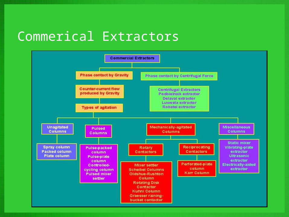
Commerical Extractors

Design of ExtractorsStage-wise ContactorsDifferential Contactors
Factors classifying Contactors
• Inducement of countercurrent flow• Designing• Effecting Phase Separation
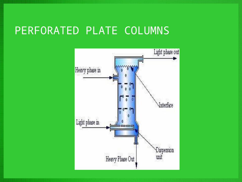
PERFORATED PLATE COLUMNS
• Similar to the sieve tray columns in distillation.• The column is comprised of several perforated trays
along with either downcomers or upcomers, depending on which phase, heavy or light, is chosen to be continuous.
• The original dispersion is performed by a nozzle, as in spray columns.
• Cross flow contact occurs between each tray.
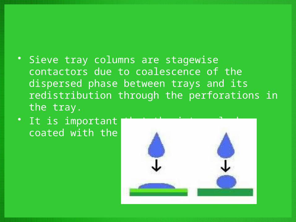
• Sieve tray columns are stagewise contactors due to coalescence of the dispersed phase between trays and its redistribution through the perforations in the tray.
• It is important that the internals be coated with the continuous phase.

Design of Perforated Plate ExtractionColumns
• Procedure developed by Skelland and Chada.• Procedure involves use of rate equations for mass
transfer during drop formation either at the perforations or at the end of jets issuing from the perforations, during free rise or fall of the drops, and during coalescence beneath each plate, to locate a pseudo-equilibrium curve.
• When flow rates of the disperse phase are low, drop formation and detachment occur at the perforations on each plate.
Design of Perforated Plate ExtractionColumns
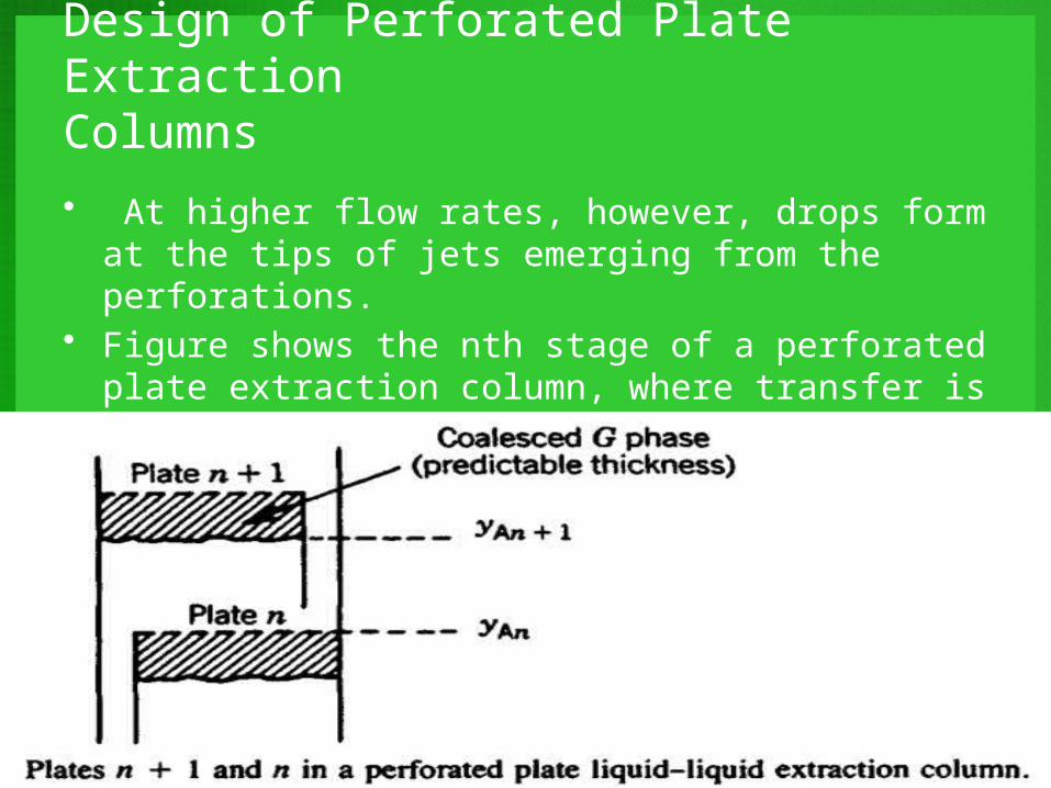
• At higher flow rates, however, drops form at the tips of jets emerging from the perforations.
• Figure shows the nth stage of a perforated plate extraction column, where transfer is from the continuous phase to the disperse phase.
Design of Perforated Plate ExtractionColumns
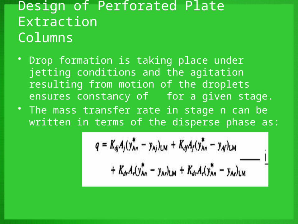
• Drop formation is taking place under jetting conditions and the agitation resulting from motion of the droplets ensures constancy of for a given stage.
• The mass transfer rate in stage n can be written in terms of the disperse phase as:
Design of Perforated Plate ExtractionColumns
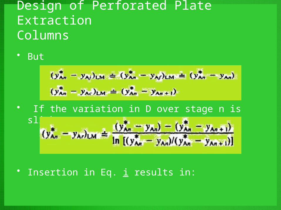
• But
• If the variation in D over stage n is slight,
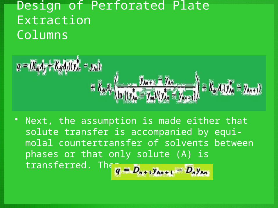
• Insertion in Eq. i results in:
Design of Perforated Plate ExtractionColumns
• c
• Next, the assumption is made either that solute transfer is accompanied by equi-molal countertransfer of solvents between phases or that only solute (A) is transferred. Then,
Design of Perforated Plate ExtractionColumns
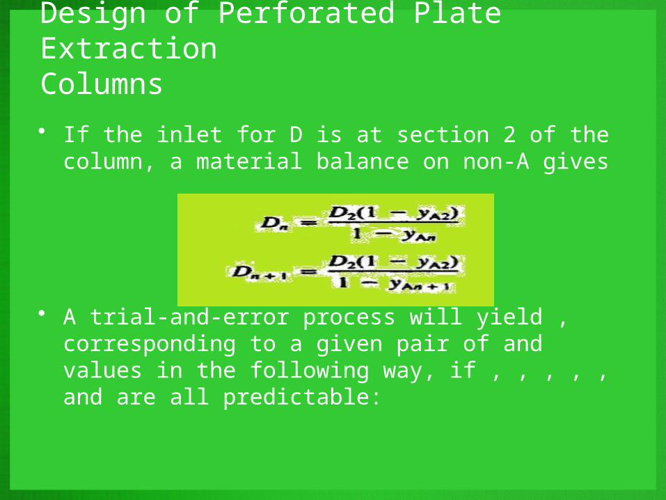
• If the inlet for D is at section 2 of the column, a material balance on non-A gives
• A trial-and-error process will yield , corresponding to a given pair of and values in the following way, if , , , , , and are all predictable:
Design of Perforated Plate ExtractionColumns
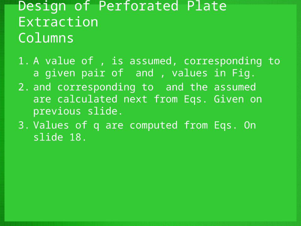
1. A value of , is assumed, corresponding to a given pair of and , values in Fig.
2. and corresponding to and the assumed are calculated next from Eqs. Given on previous slide.
3. Values of q are computed from Eqs. On slide 18.
Design of Perforated Plate ExtractionColumns
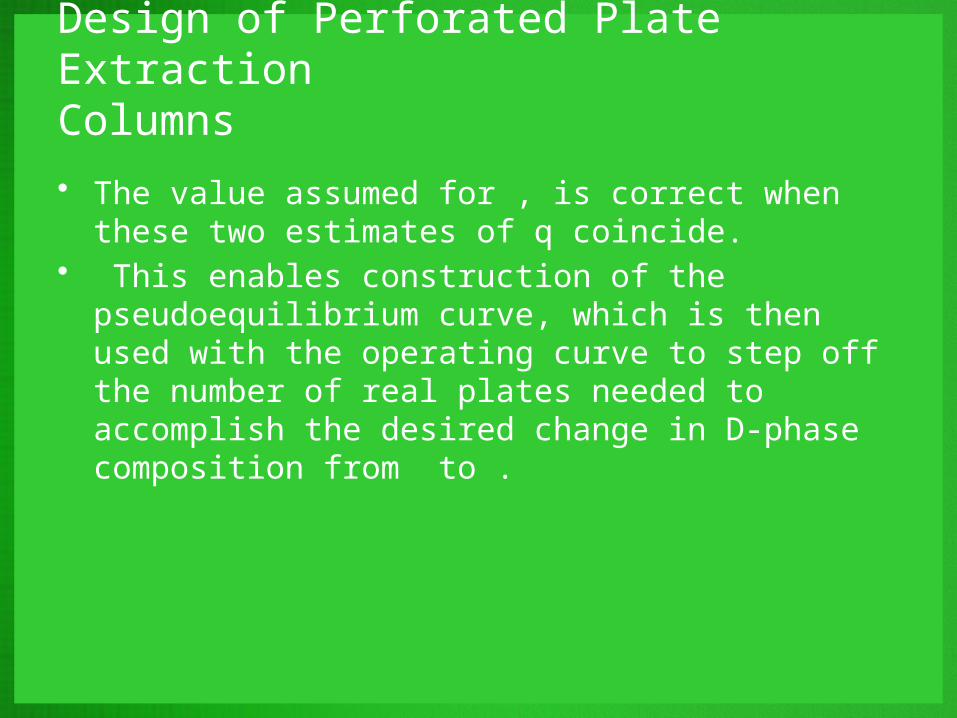
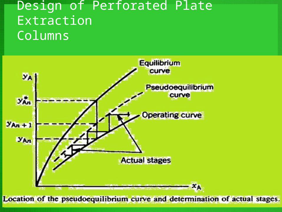
• The value assumed for , is correct when these two estimates of q coincide.
• This enables construction of the pseudoequilibrium curve, which is then used with the operating curve to step off the number of real plates needed to accomplish the desired change in D-phase composition from to .
Design of Perforated Plate ExtractionColumns