performance analysis for voip system members r94922009 周宜穎 r94922009 周宜穎 r94922020...
TRANSCRIPT

Performance Analysis for VoIPerformance Analysis for VoIP SystemP System
MembersMembers R94922009 R94922009 周宜穎周宜穎 R94922020 R94922020 吳鴻鑫吳鴻鑫 R94922064 R94922064 張嘉輔張嘉輔
OutlineOutline
What is PerformanceWhat is Performance
Performance BoundPerformance Bound
How to analyze PerformanceHow to analyze Performance
Some Performance Analysis ExmapleSome Performance Analysis Exmaple
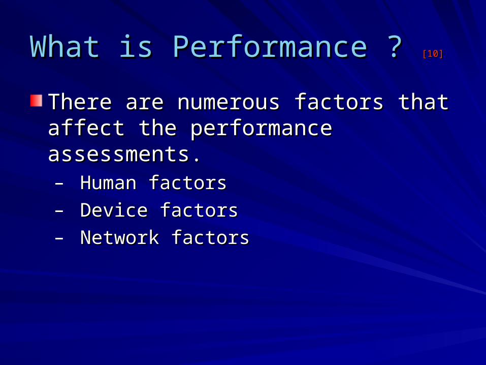
What is Performance ? What is Performance ? [10][10]
There are numerous factors that affect the There are numerous factors that affect the performance assessments. performance assessments. – Human factors Human factors – Device factors Device factors – Network factors Network factors
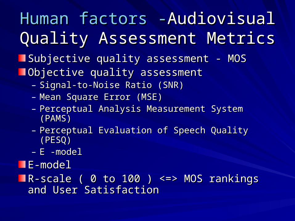
Human factors -Human factors -Audiovisual Quality Audiovisual Quality Assessment MetricsAssessment Metrics
Subjective quality assessment - MOS Subjective quality assessment - MOS Objective quality assessment Objective quality assessment – Signal-to-Noise Ratio (SNR) Signal-to-Noise Ratio (SNR) – Mean Square Error (MSE)Mean Square Error (MSE)– Perceptual Analysis Measurement System (PAMS) Perceptual Analysis Measurement System (PAMS) – Perceptual Evaluation of Speech Quality (PESQ) Perceptual Evaluation of Speech Quality (PESQ) – E -model E -model
E-model E-model R-scale ( 0 to 100 ) <=> MOS rankings and User R-scale ( 0 to 100 ) <=> MOS rankings and User SatisfactionSatisfaction
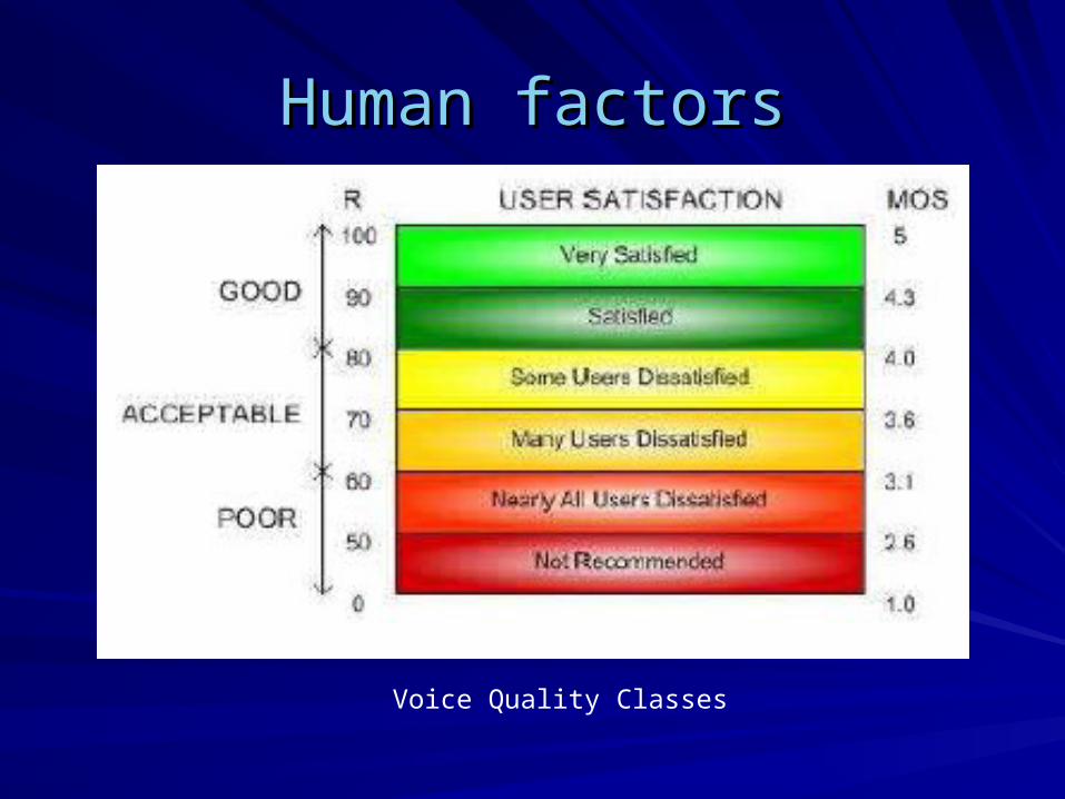
Human factorsHuman factors
Voice Quality Classes
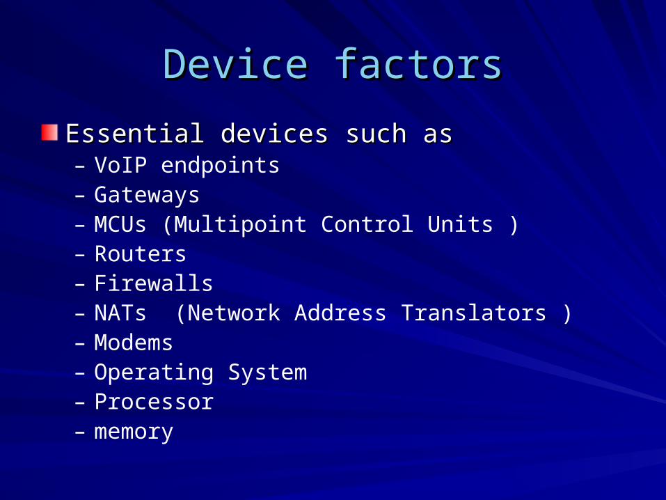
Device factorsDevice factors
Essential devices such as Essential devices such as – VoIP endpoints– Gateways– MCUs (Multipoint Control Units )– Routers– Firewalls – NATs (Network Address Translators )– Modems– Operating System– Processor– memory
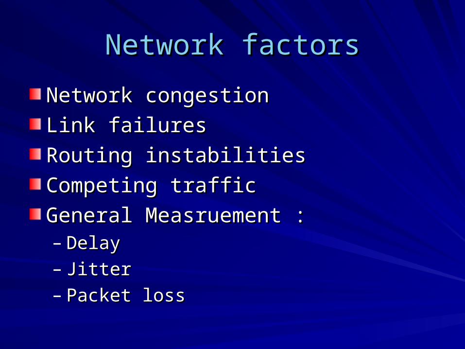
Network factorsNetwork factors
Network congestionNetwork congestion
Link failures Link failures
Routing instabilitiesRouting instabilities
Competing traffic Competing traffic
General Measruement :General Measruement :– DelayDelay– JitterJitter– Packet loss Packet loss
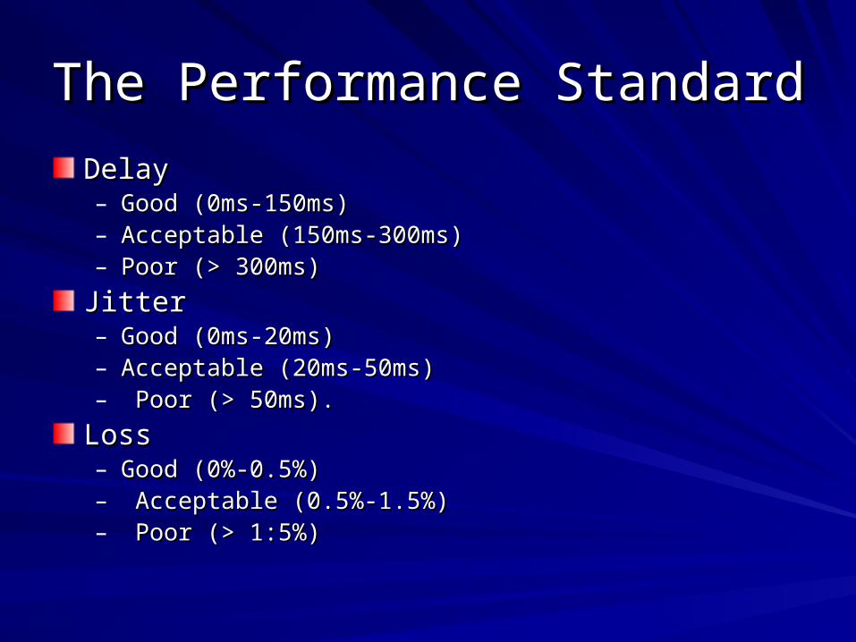
The Performance StandardThe Performance Standard
Delay Delay – Good (0ms-150ms)Good (0ms-150ms)– Acceptable (150ms-300ms)Acceptable (150ms-300ms)– Poor (> 300ms)Poor (> 300ms)
JitterJitter– Good (0ms-20ms)Good (0ms-20ms)– Acceptable (20ms-50ms)Acceptable (20ms-50ms)– Poor (> 50ms).Poor (> 50ms).
LossLoss– Good (0%-0.5%)Good (0%-0.5%)– Acceptable (0.5%-1.5%)Acceptable (0.5%-1.5%)– Poor (> 1:5%)Poor (> 1:5%)
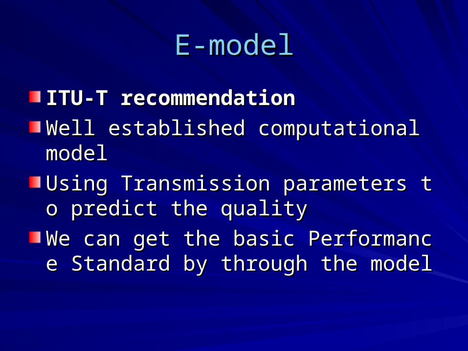
E-modelE-model
ITU-T recommendationITU-T recommendation
Well established computational model Well established computational model
Using Transmission parameters to predict Using Transmission parameters to predict the qualitythe quality
We can get the basic Performance StandaWe can get the basic Performance Standard by through the modelrd by through the model
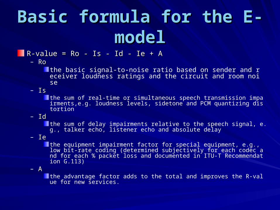
Basic formula for the E-modelBasic formula for the E-model
R-value = Ro - Is - Id - Ie + AR-value = Ro - Is - Id - Ie + A– Ro Ro
the basic signal-to-noise ratio based on sender and receiver loudness ratings and the circuit and room noise
– Is Is the sum of real-time or simultaneous speech transmission impairments,e.g. loudness levels, sidetone and PCM quantizing distortion
– Id Id the sum of delay impairments relative to the speech signal, e.g., talker echo, listener echo and absolute delay
– Ie Ie the equipment impairment factor for special equipment, e.g., low bit-rate coding (determined subjectively for each codec and for each % packet loss and documented in ITU-T Recommendation G.113)
– A A the advantage factor adds to the total and improves the R-value for new services.
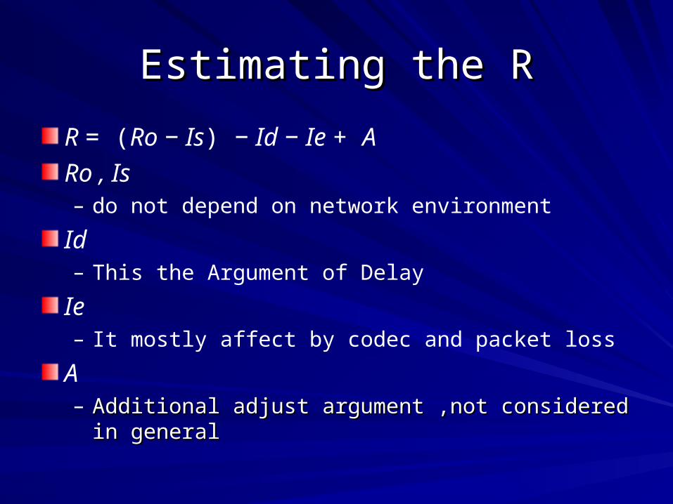
Estimating the REstimating the R
R = (Ro − Is) − Id − Ie + A
Ro , Is – do not depend on network environment
Id– This the Argument of Delay
Ie – It mostly affect by codec and packet loss
A– Additional adjust argument ,not considered in generalAdditional adjust argument ,not considered in general
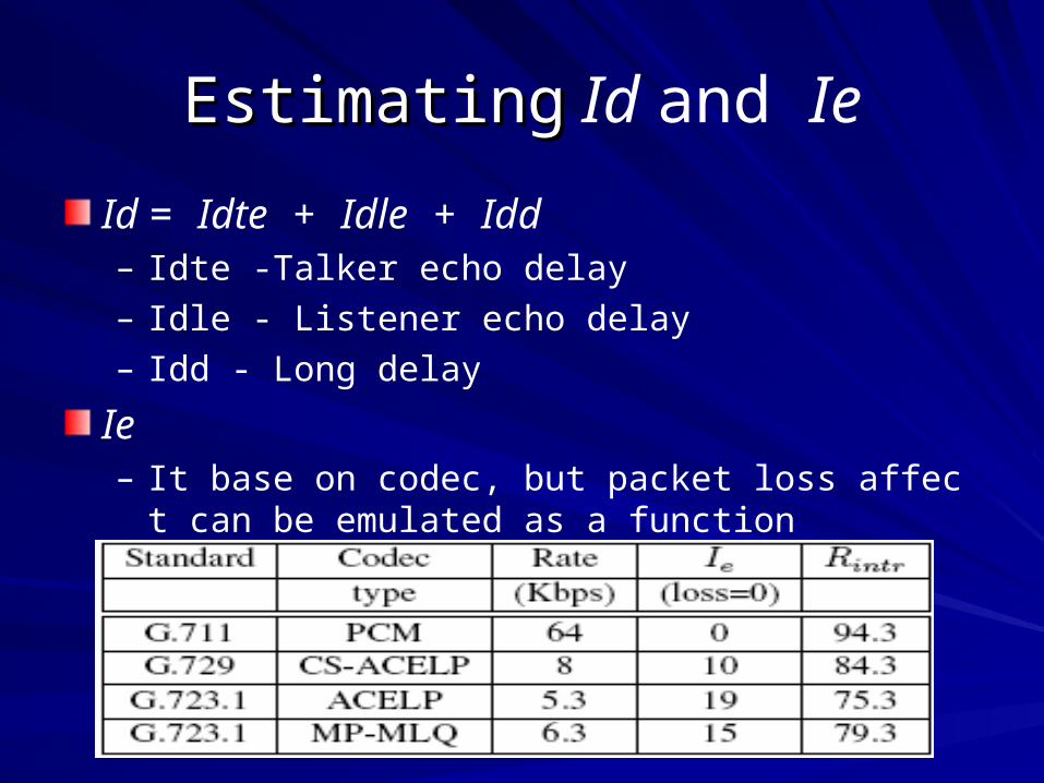
EstimatingEstimating Id and Ie
Id = Idte + Idle + Idd– Idte -Talker echo delay– Idle - Listener echo delay– Idd - Long delay
Ie– It base on codec, but packet loss affect can be emula
ted as a function
EstimatingEstimating Id and Ie
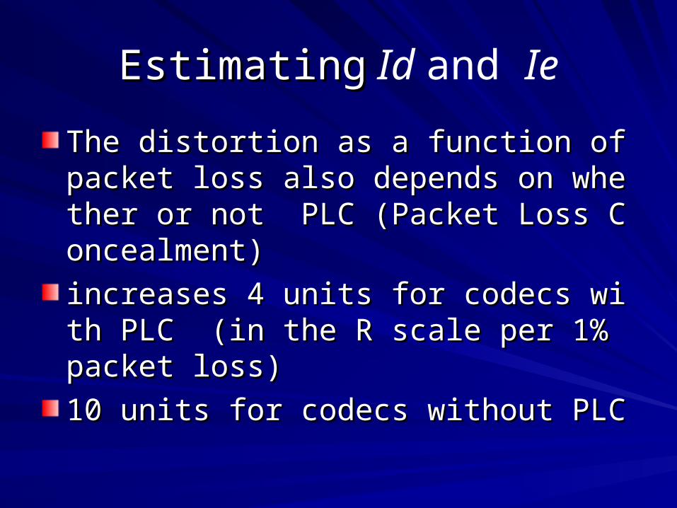
The distortion as a function of packet loss The distortion as a function of packet loss also depends on whether or not PLC (Pacalso depends on whether or not PLC (Packet Loss Concealment)ket Loss Concealment)
increases 4 units for codecs with PLC (in tincreases 4 units for codecs with PLC (in the R scale per 1% packet loss)he R scale per 1% packet loss)
10 units for codecs without PLC10 units for codecs without PLC

Curve DiagramCurve Diagram
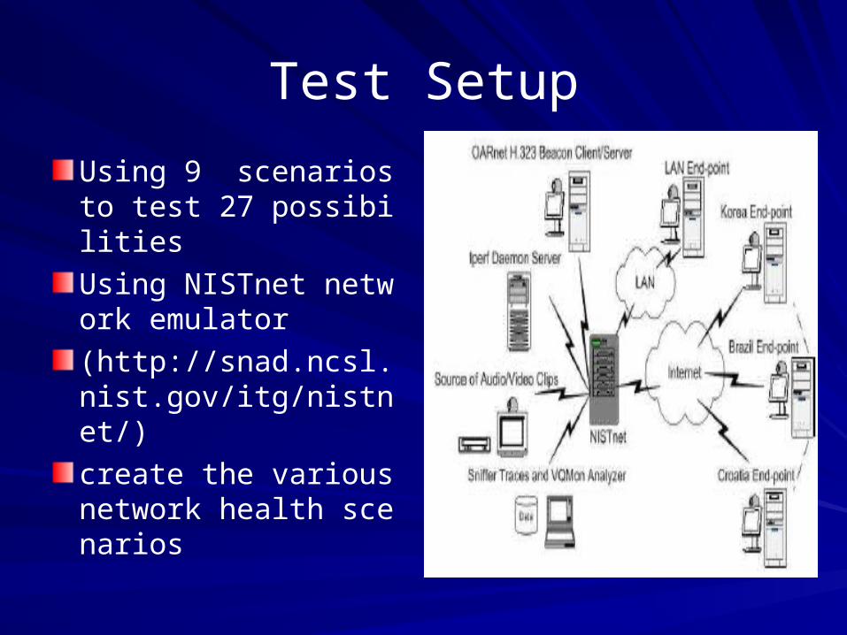
Test Setup
Using 9 scenarios to test 27 possibilities
Using NISTnet network emulator
(http://snad.ncsl.nist.gov/itg/nistnet/)
create the various network health scenarios
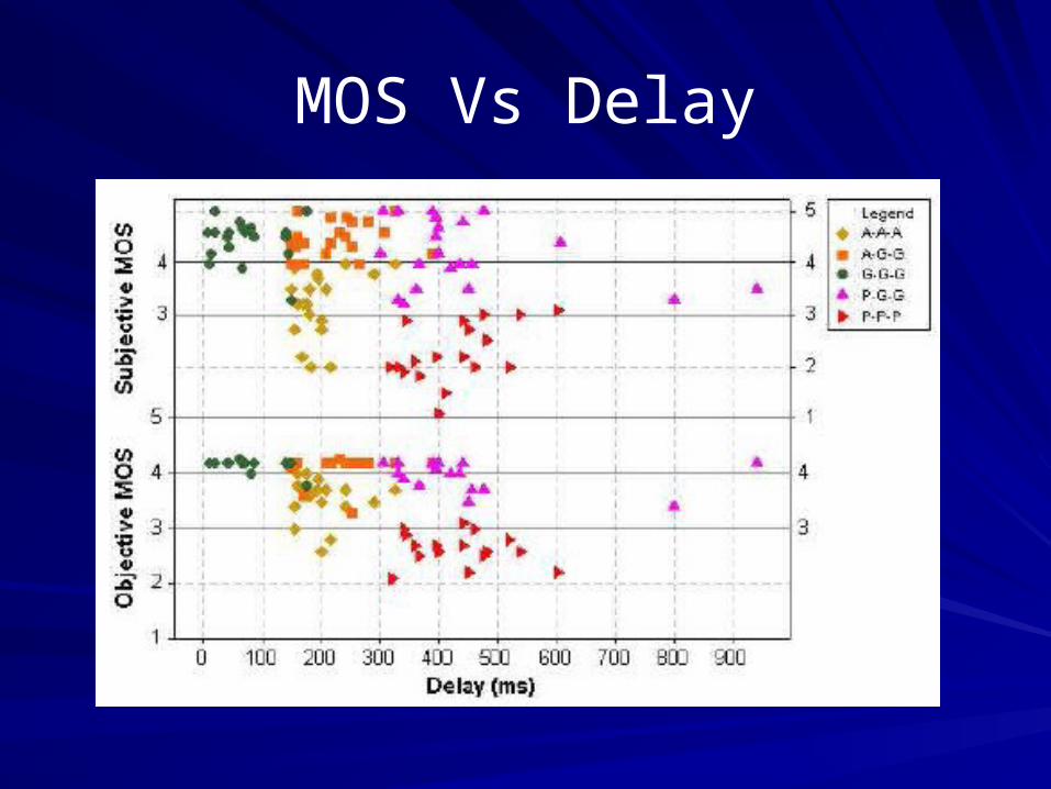
MOS Vs Delay

MOS Vs Jitter
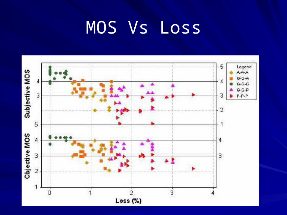
MOS Vs Loss
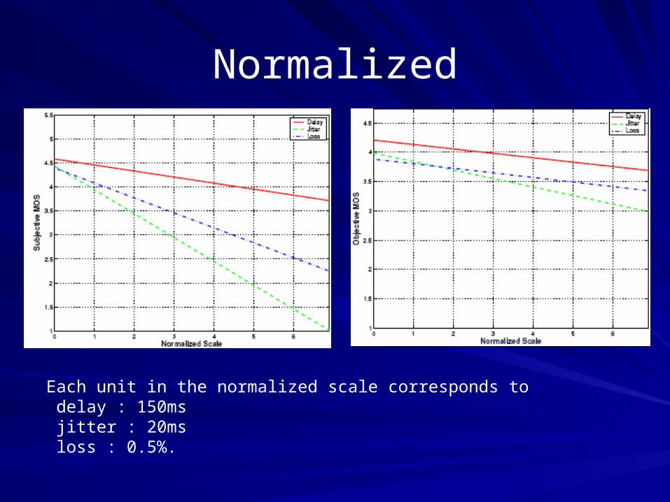
Normalized
Each unit in the normalized scale corresponds to delay : 150ms jitter : 20ms loss : 0.5%.
The Conclusion about Performance The Conclusion about Performance boundsbounds
We show that end-user perception of audiovisual quality is more sensitive to the variations in end-to-end jitter than to variations in delay or loss
We get a simple standard about the Performance to estimate Performance
How to Analyze PerformanceHow to Analyze Performance
Thinking about two topicThinking about two topic– MeasurementMeasurement– Network ConditionNetwork Condition
Measurement mean the analysis model Measurement mean the analysis model that estimate that estimate key parameters
Of course, it is the way to compute delay, jitter ,packet loss
Two Measurement Two Measurement [7],[8],[9][7],[8],[9]
There are two methods in performance measurement
passive measurement – records and analyzes existing traffic.
active measurement – Inject sample packets into the network.
Introduce a simple MeasureIntroduce a simple Measure
Measurement Method in LAN
sends sequences of UDP packets to unlikely values of destination port numbers (larger than 30,000)
This causes the destination host’s UDP module to generate an ICMP port unreachable error when the datagram arrives
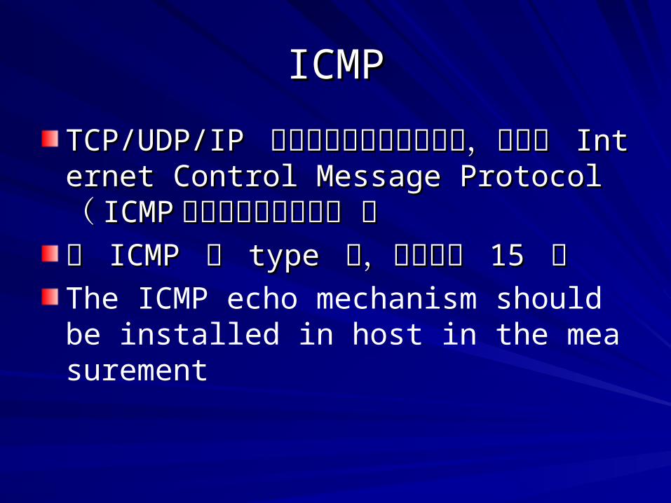
ICMPICMP
TCP/UDP/IP TCP/UDP/IP 協定若有錯誤情形發生時,協定若有錯誤情形發生時,會利用 會利用 Internet Control Message ProtocolInternet Control Message Protocol(( ICMPICMP )協定來送錯誤訊息 。)協定來送錯誤訊息 。在 在 ICMP ICMP 的 的 type type 中,目前約有 中,目前約有 15 15 種 種 The ICMP echo mechanism should be installed in host in the measurement
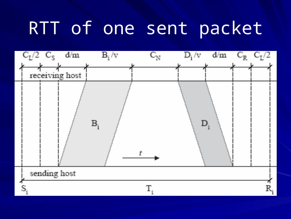
RTT of one sent packet
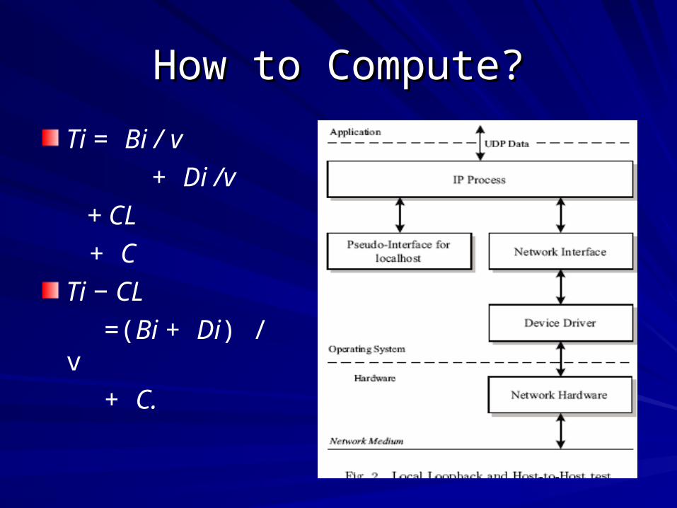
How to Compute?How to Compute?
Ti = Bi / v
+ Di /v
+ CL
+ C
Ti − CL
=(Bi + Di) / v
+ C.
Keep estimatingKeep estimating
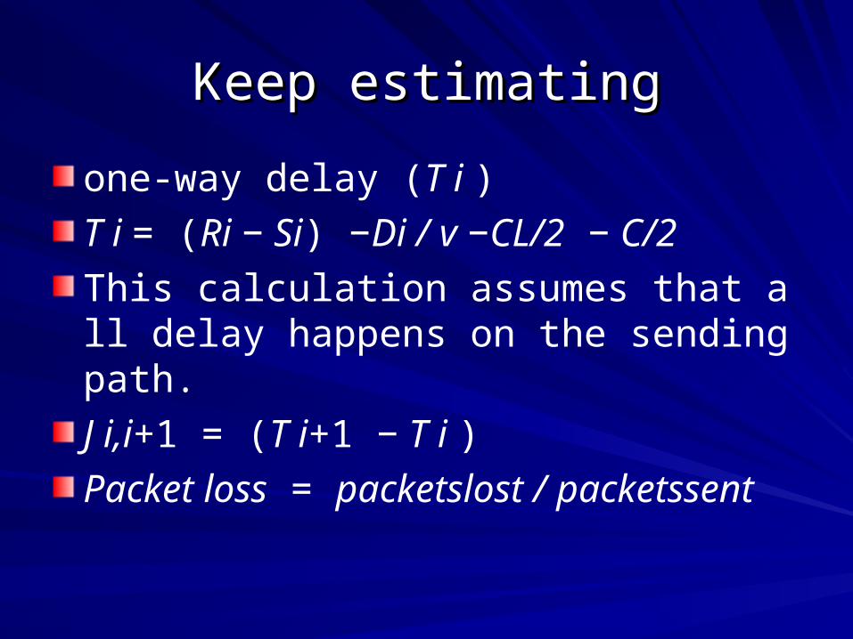
one-way delay (T i )
T i = (Ri − Si) −Di / v −CL/2 − C/2
This calculation assumes that all delay happens on the sending path.
J i,i+1 = (T i+1 − T i )
Packet loss = packetslost / packetssent
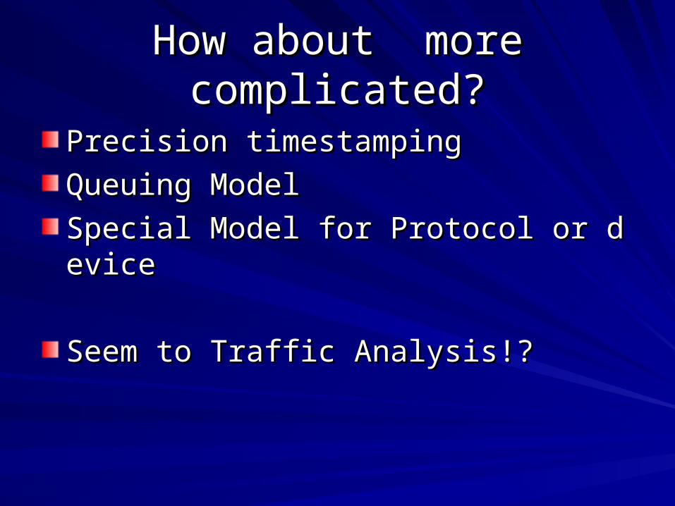
How about more complicated?How about more complicated?
Precision timestampingPrecision timestamping
Queuing ModelQueuing Model
Special Model for Protocol or deviceSpecial Model for Protocol or device
Seem to Traffic Analysis!?Seem to Traffic Analysis!?
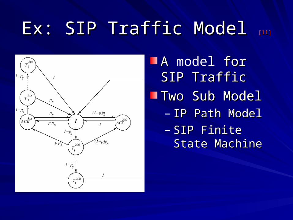
Ex: SIP Traffic Model Ex: SIP Traffic Model [11][11]
A A model for SIP for SIP TrafficTraffic
Two Sub ModelTwo Sub Model– IP Path ModelIP Path Model– SIP Finite State SIP Finite State
MachineMachine
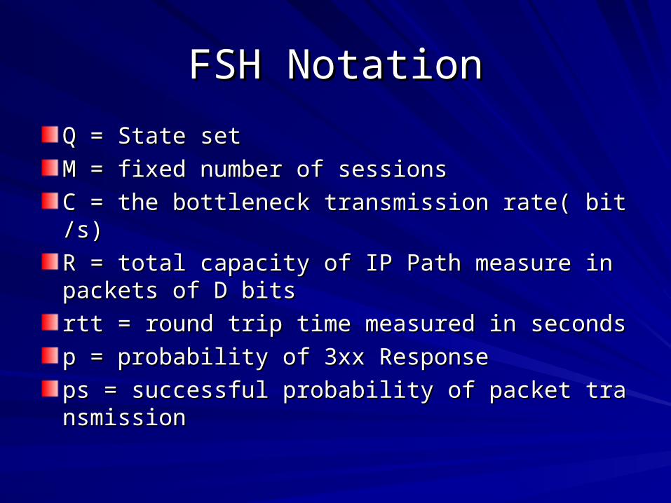
FSH NotationFSH Notation
Q = State setQ = State set
M = fixed number of sessionsM = fixed number of sessions
C = the bottleneck transmission rate( bit/s)C = the bottleneck transmission rate( bit/s)
R = total capacity of IP Path measure in packets R = total capacity of IP Path measure in packets of D bitsof D bits
rtt = round trip time measured in secondsrtt = round trip time measured in seconds
p = probability of 3xx Responsep = probability of 3xx Response
ps = successful probability of packet transmissiops = successful probability of packet transmissionn
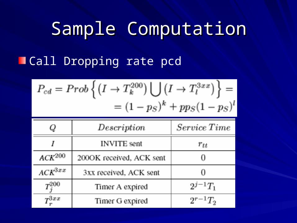
Sample ComputationSample Computation
Call Dropping rate pcd
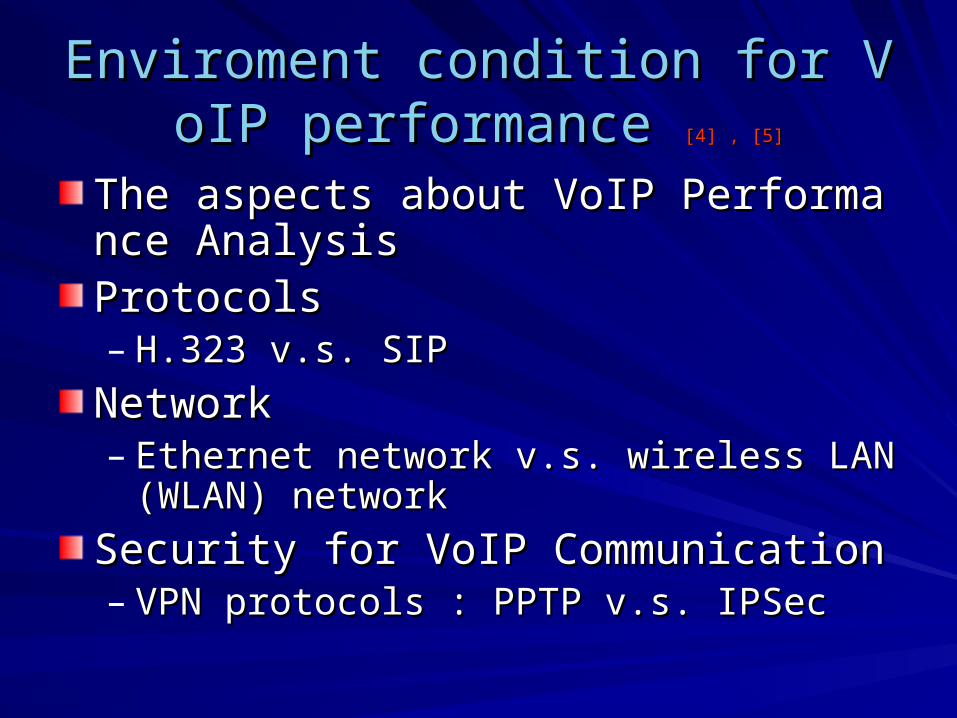
Enviroment condition for VoIP perfoEnviroment condition for VoIP performance rmance [4] , [5][4] , [5]
The aspects about VoIP Performance AnalThe aspects about VoIP Performance AnalysisysisProtocols Protocols – H.323 v.s. SIPH.323 v.s. SIP
NetworkNetwork– Ethernet network v.s. wireless LAN (WLAN) nEthernet network v.s. wireless LAN (WLAN) n
etworketwork
Security for VoIP Communication Security for VoIP Communication – VPN protocols : PPTP v.s. IPSec VPN protocols : PPTP v.s. IPSec
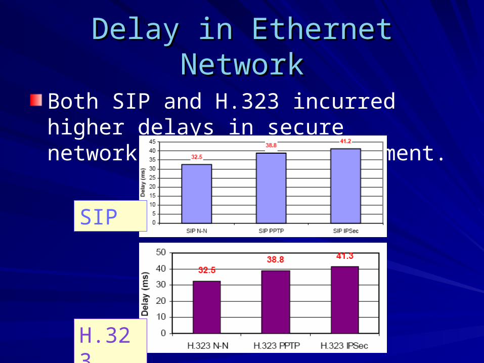
Delay in Ethernet NetworkDelay in Ethernet Network
Both SIP and H.323 incurred higher delays in secure network-to-network environment.
SIP
H.323
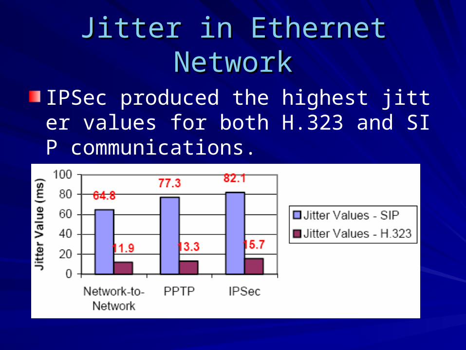
Jitter in Ethernet NetworkJitter in Ethernet Network
IPSec produced the highest jitter values for both H.323 and SIP communications.
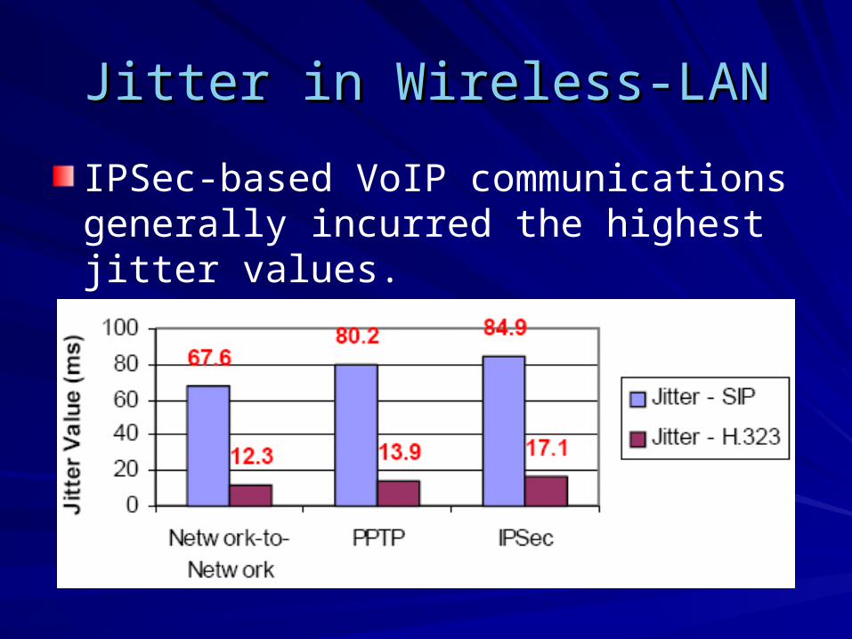
Jitter in Wireless-LANJitter in Wireless-LAN
IPSec-based VoIP communications generally incurred the highest jitter values.

Packet Loss RatesPacket Loss Rates
IPSec and PPTP increased the packet loss rate in both Ethernet and WLAN.
SIP
H.323
Performance in Satellite Network Performance in Satellite Network [1][1]
Also provides IP-base data servicesAlso provides IP-base data services
For remote regionFor remote region
As backup linksAs backup links
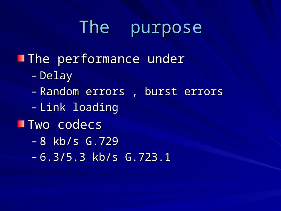
The purposeThe purpose
The performance underThe performance under– DelayDelay– Random errors , burst errorsRandom errors , burst errors– Link loadingLink loading
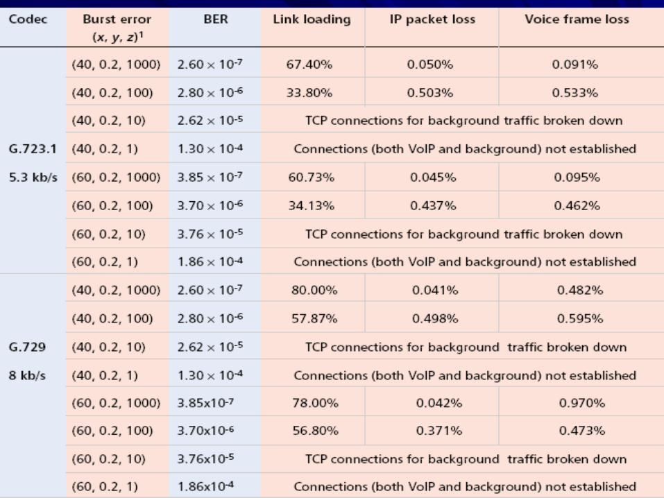
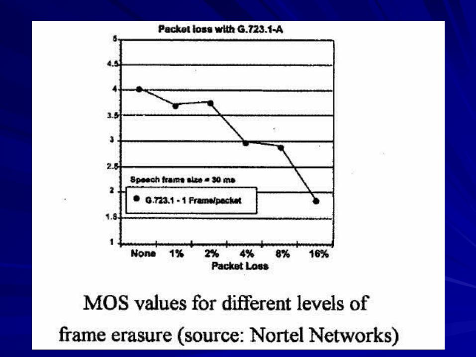
Two codecsTwo codecs– 8 kb/s G.7298 kb/s G.729– 6.3/5.3 kb/s G.723.16.3/5.3 kb/s G.723.1
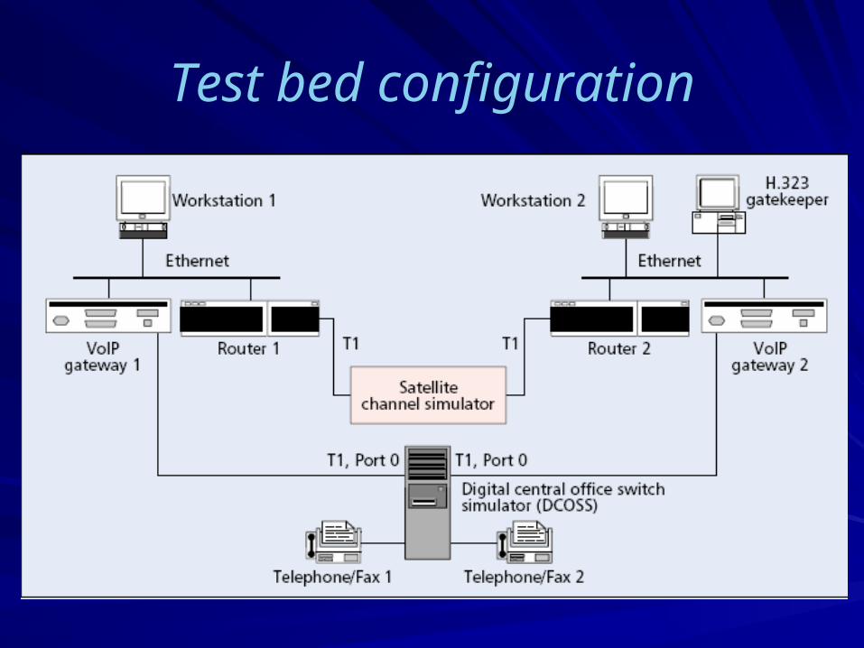
Test bed configuration
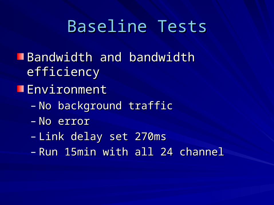
Baseline TestsBaseline Tests
Bandwidth and bandwidth efficiencyBandwidth and bandwidth efficiency
EnvironmentEnvironment– No background trafficNo background traffic– No errorNo error– Link delay set 270msLink delay set 270ms– Run 15min with all 24 channel Run 15min with all 24 channel
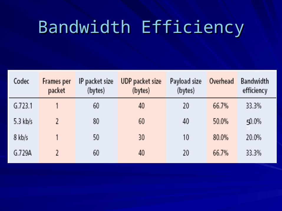
Bandwidth EfficiencyBandwidth Efficiency
55
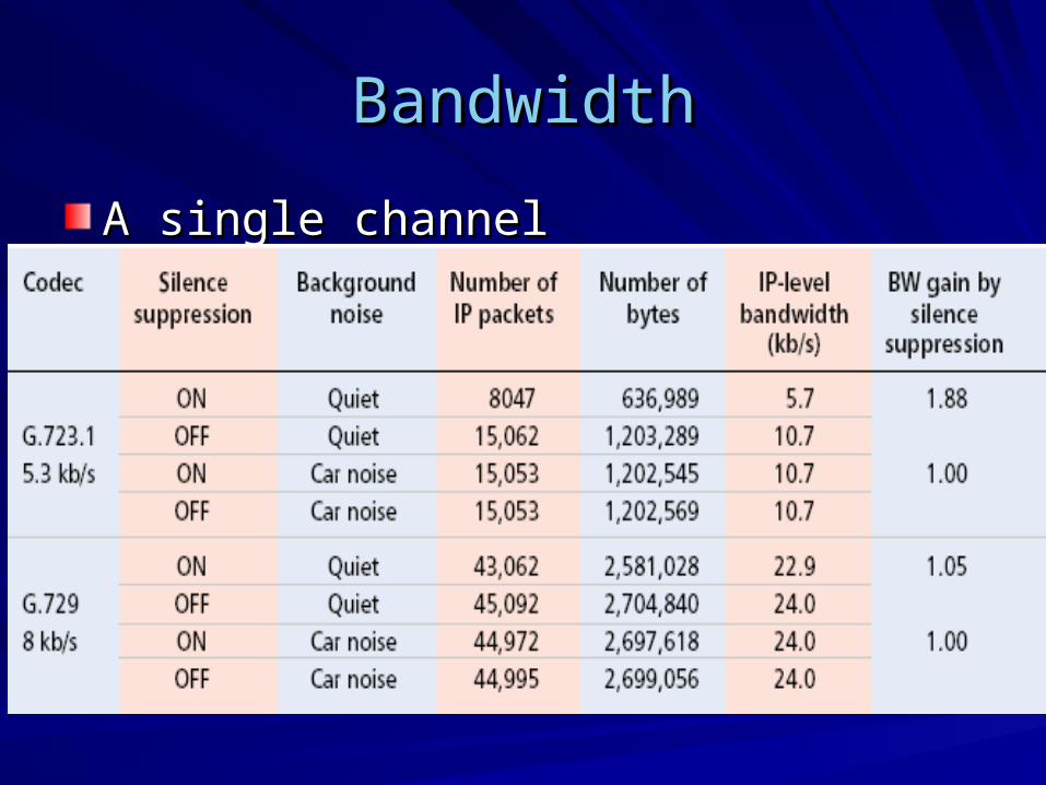
BandwidthBandwidth
A single channelA single channel
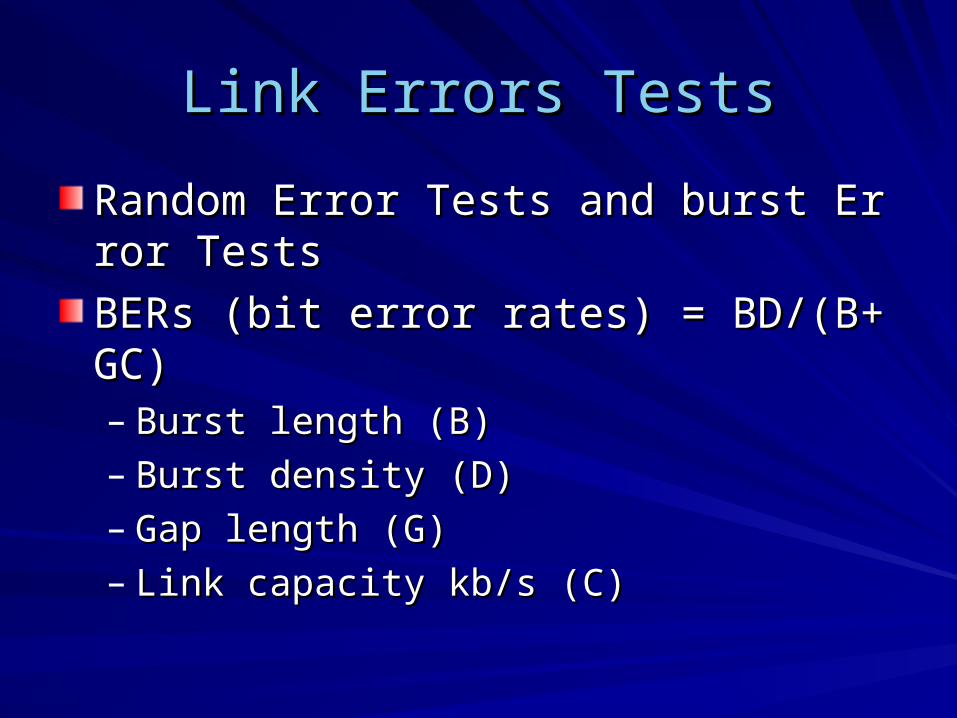
Link Errors TestsLink Errors Tests
Random Error Tests and burst Error TestsRandom Error Tests and burst Error Tests
BERs (bit error rates) = BD/(B+GC)BERs (bit error rates) = BD/(B+GC)– Burst length (B)Burst length (B)– Burst density (D)Burst density (D)– Gap length (G)Gap length (G)– Link capacity kb/s (C)Link capacity kb/s (C)
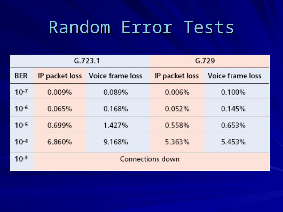
Random Error TestsRandom Error Tests
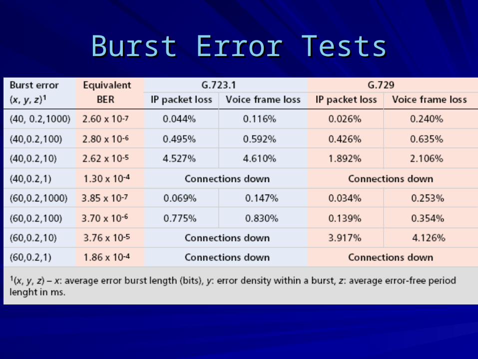
Burst Error TestsBurst Error Tests
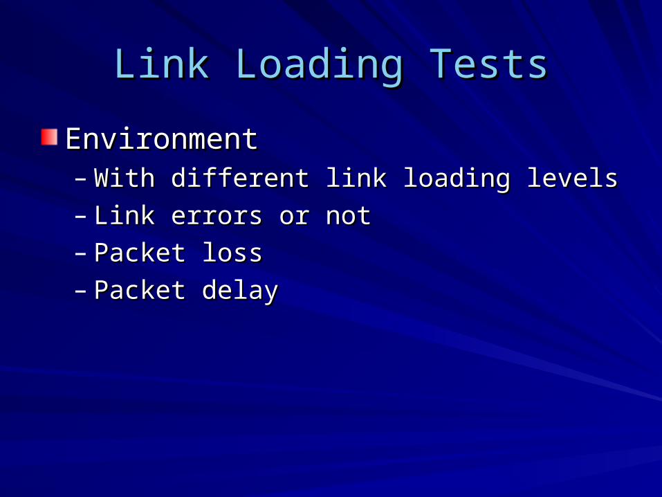
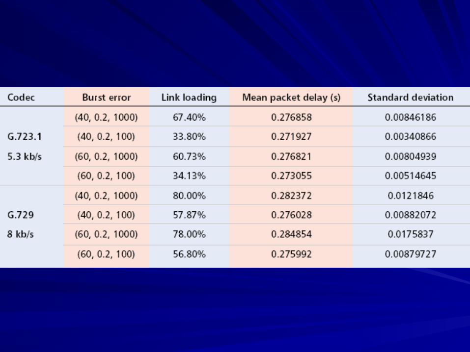
Link Loading TestsLink Loading Tests
EnvironmentEnvironment– With different link loading levelsWith different link loading levels– Link errors or notLink errors or not– Packet lossPacket loss– Packet delayPacket delay
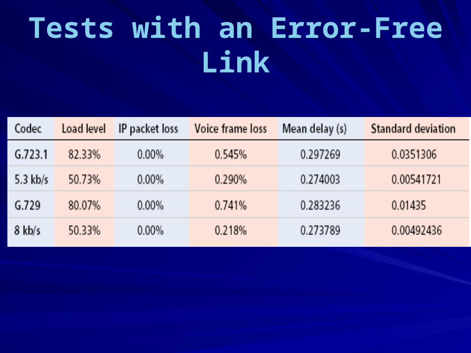
Tests with an Error-Free Link
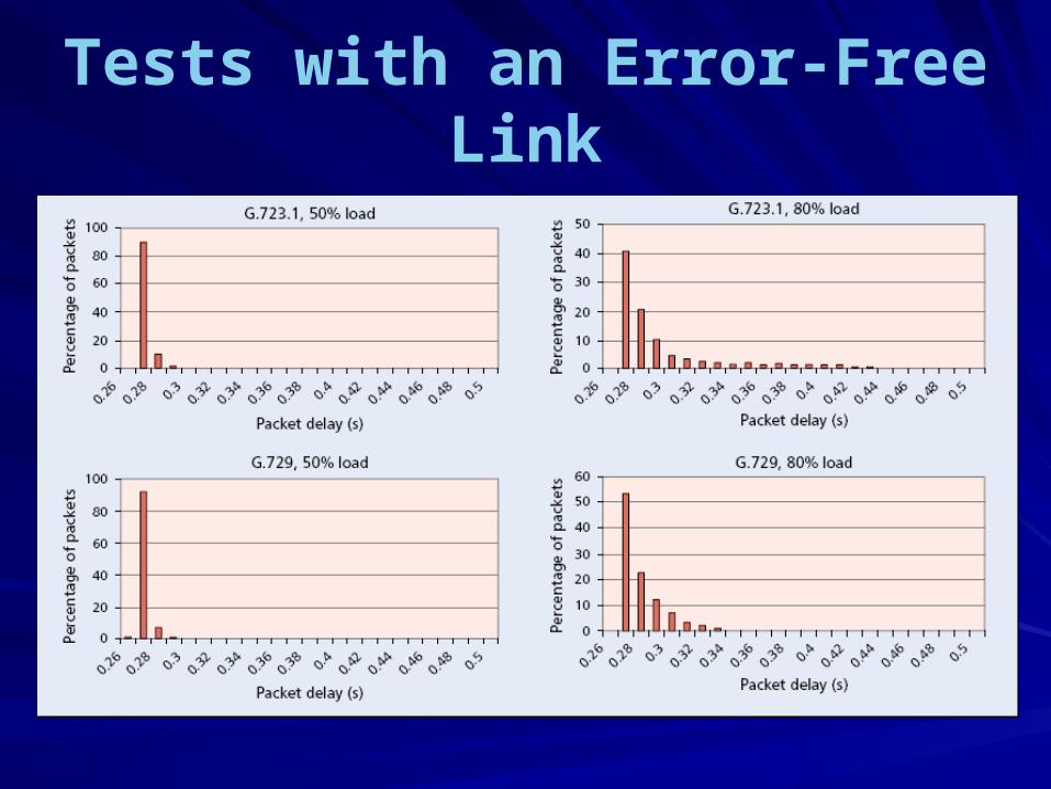
Tests with an Error-Free Link
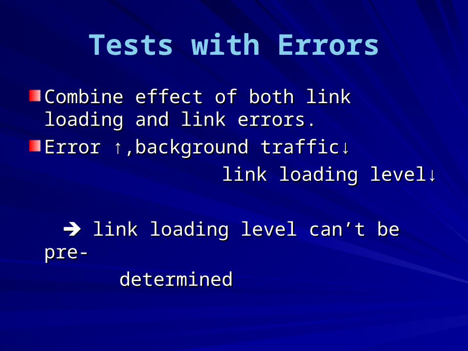
Tests with Errors
Combine effect of both link loading and Combine effect of both link loading and link errors.link errors.
Error ↑,background traffic↓Error ↑,background traffic↓
link loading level↓link loading level↓
link loading level can’t be pre- link loading level can’t be pre-
determineddetermined
Impact of link failures on VoIP pImpact of link failures on VoIP performance erformance [3][3]
Three major causes of performance degradationThree major causes of performance degradation– network congestionnetwork congestion– link failureslink failures– routing instabilitiesrouting instabilities
Congestion is always negligible.
Link failures may be followed by long periods of rLink failures may be followed by long periods of routing instability.outing instability.
The goal is to study the impact of link failures on The goal is to study the impact of link failures on VoIP performance.VoIP performance.
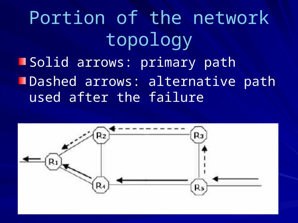
Portion of the network topology
Solid arrows: primary path
Dashed arrows: alternative path used after the failure
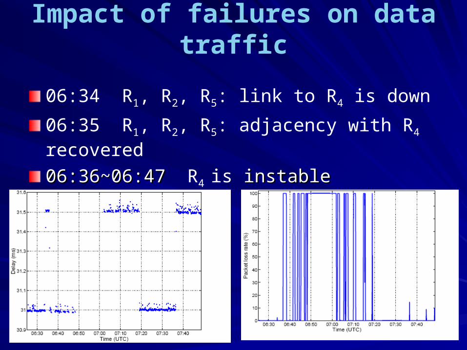
Impact of failures on data traffic
06:34 R1, R2, R5: link to R4 is down
06:35 R1, R2, R5: adjacency with R4 recovered
06:36~06:47 06:36~06:47 R4 is instableinstable
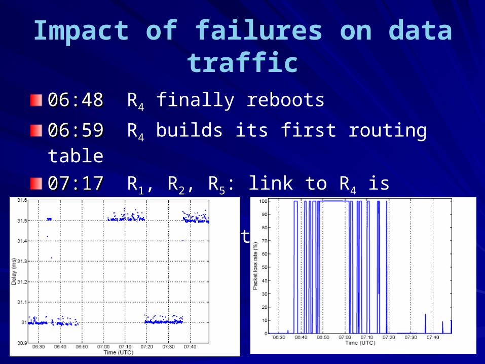
Impact of failures on data traffic
06:48 06:48 R4 finally reboots
06:59 06:59 R4 builds its first routing table
07:17 07:17 R1, R2, R5: link to R4 is definitely up
07:36 an alternative path is chosen
Impact of failures on data traffic
the failure we observed in four phases– 06:34 link is down, delay↑, few packet loss– 06:36~06:47 router router is instable, same delay, instable, same delay,
packet loss↑packet loss↑– 06:48~07:04 router reboots, no delay, packet packet
loss↑loss↑– 07:05~07:17 07:05~07:17 router builds routing table,
delay↑, packet loss↑
ReferencsReferencs
[1]Voice over IP Service and Performance in Satellite Network, IEEE Communication[1]Voice over IP Service and Performance in Satellite Network, IEEE Communications Magazines Magazine
[2]Technique for Performance Improvement of VoIP Applications, IEEE MELECON 2[2]Technique for Performance Improvement of VoIP Applications, IEEE MELECON 2002002
[3]Impact of link failures on VoIP performance, ACM 1-58113-512-2/02/0005[3]Impact of link failures on VoIP performance, ACM 1-58113-512-2/02/0005
[4]VoIP Performance Measure Using Qos Parameters , The Second International Con[4]VoIP Performance Measure Using Qos Parameters , The Second International Conference ference
[5]VoIP Performance Management, Internet Telephony Fall 2005[5]VoIP Performance Management, Internet Telephony Fall 2005
[6]Comparative Analysis of Traditional Telephone and VoIP System[6]Comparative Analysis of Traditional Telephone and VoIP System
[7]VoIP Performance on differenriate service[7]VoIP Performance on differenriate service
[8]Measuring Voice Readiness of Local Area Networks[8]Measuring Voice Readiness of Local Area Networks
[9]Experimental Investigation of the Relationship between IP Network Performances [9]Experimental Investigation of the Relationship between IP Network Performances and Speech Quality of VoIPand Speech Quality of VoIP
[10]Performance Measurement and Analysis of H.323 Traffic[10]Performance Measurement and Analysis of H.323 Traffic
[11][11] A Technique to Analyse Session Initiation Protocol Traffic A Technique to Analyse Session Initiation Protocol Traffic
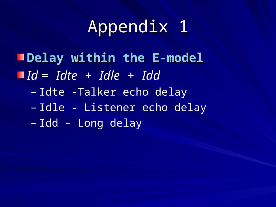
Appendix 1Appendix 1
Delay within the E-modelDelay within the E-model
Id = Idte + Idle + Idd– Idte -Talker echo delay– Idle - Listener echo delay– Idd - Long delay
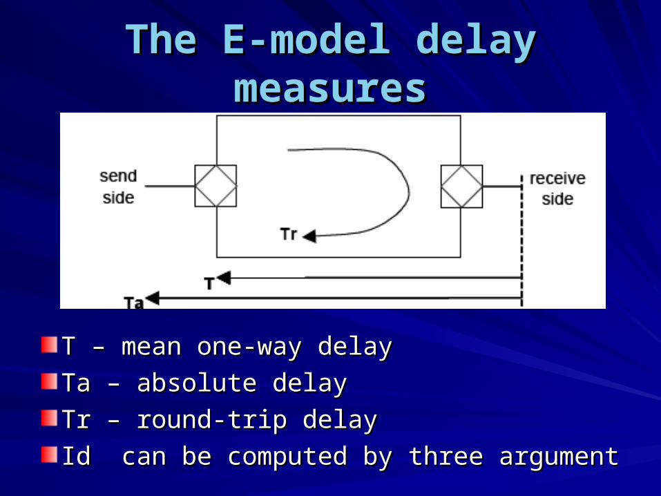
The E-model delay measuresThe E-model delay measures
T – mean one-way delayT – mean one-way delay
Ta – absolute delayTa – absolute delay
Tr – round-trip delayTr – round-trip delay
Id can be computed by three argumentId can be computed by three argument
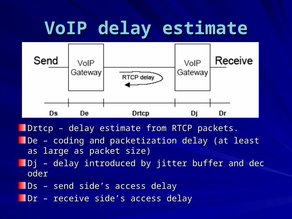
VoIP delay estimateVoIP delay estimate
Drtcp – delay estimate from RTCP packets.Drtcp – delay estimate from RTCP packets.
De – coding and packetization delay (at least as large De – coding and packetization delay (at least as large as packet size)as packet size)
Dj – delay introduced by jitter buffer and decoderDj – delay introduced by jitter buffer and decoder
Ds – send side’s access delayDs – send side’s access delay
Dr – receive side’s access delayDr – receive side’s access delay
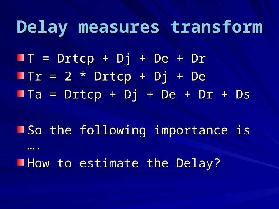
Delay measures transformDelay measures transform
T = Drtcp + Dj + De + DrT = Drtcp + Dj + De + Dr
Tr = 2 * Drtcp + Dj + DeTr = 2 * Drtcp + Dj + De
Ta = Drtcp + Dj + De + Dr + DsTa = Drtcp + Dj + De + Dr + Ds
So the following importance is ….So the following importance is ….
How to estimate the Delay? How to estimate the Delay?
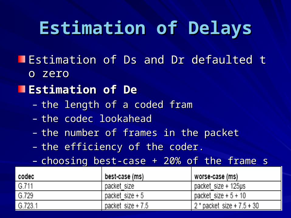
Estimation of DelaysEstimation of Delays
Estimation of Ds and Dr defaulted to zero Estimation of Ds and Dr defaulted to zero
Estimation of DeEstimation of De– the length of a coded framthe length of a coded fram– the codec lookaheadthe codec lookahead– the number of frames in the packetthe number of frames in the packet– the efficiency of the coder. the efficiency of the coder. – choosing best-case + 20% of the frame size would bchoosing best-case + 20% of the frame size would b
e a reasonable estimate of encoding delay e a reasonable estimate of encoding delay
Estimation of DelaysEstimation of Delays
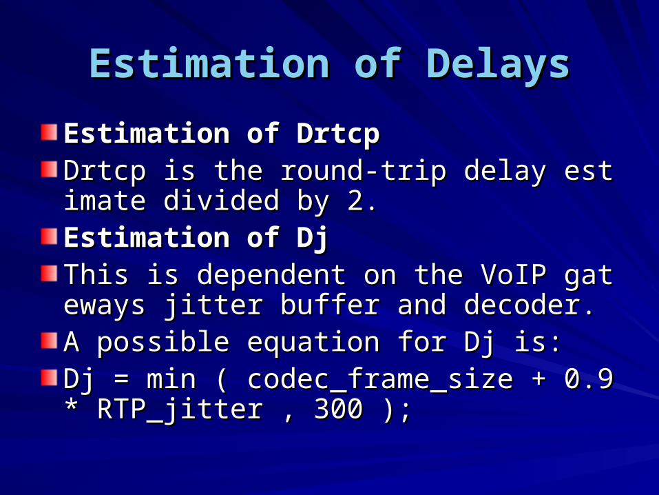
Estimation of DrtcpEstimation of DrtcpDrtcp is the round-trip delay estimate dividDrtcp is the round-trip delay estimate divided by 2.ed by 2.Estimation of DjEstimation of DjThis is dependent on the VoIP gateways jitThis is dependent on the VoIP gateways jitter buffer and decoder. ter buffer and decoder. A possible equation for Dj is:A possible equation for Dj is:Dj = min ( codec_frame_size + 0.9 * RTP_jDj = min ( codec_frame_size + 0.9 * RTP_jitter , 300 );itter , 300 );
Appendix 2Appendix 2
QosQos
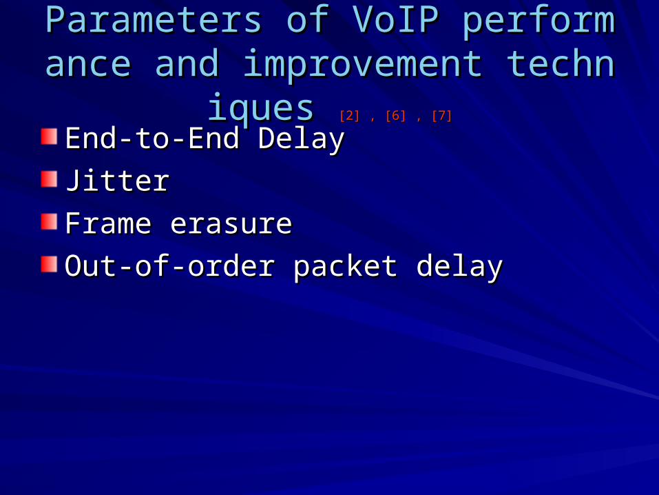
Parameters of VoIP performance aParameters of VoIP performance and improvement techniques nd improvement techniques [2] , [6] , [7][2] , [6] , [7]
End-to-End DelayEnd-to-End Delay
JitterJitter
Frame erasureFrame erasure
Out-of-order packet delayOut-of-order packet delay
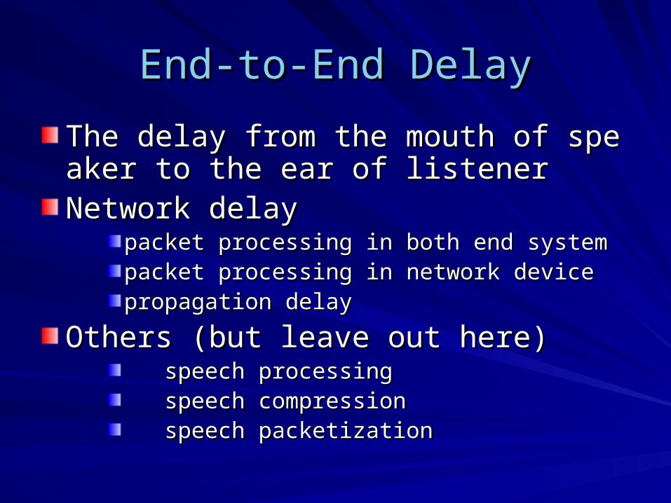
End-to-End DelayEnd-to-End Delay
The delay from the mouth of speaker to thThe delay from the mouth of speaker to the ear of listenere ear of listenerNetwork delayNetwork delay
packet processing in both end system packet processing in both end system packet processing in network devicepacket processing in network devicepropagation delay propagation delay
Others (but leave out here)Others (but leave out here) speech processing speech processing speech compression speech compression speech packetizationspeech packetization

Network delayNetwork delay
fixed part fixed part In every network note (router) IP packets are In every network note (router) IP packets are delayed delayed
propagation delaypropagation delay
transmission delay transmission delay
variable part variable part the time spent in queues of the network nodes on the time spent in queues of the network nodes on the transmission path the transmission path
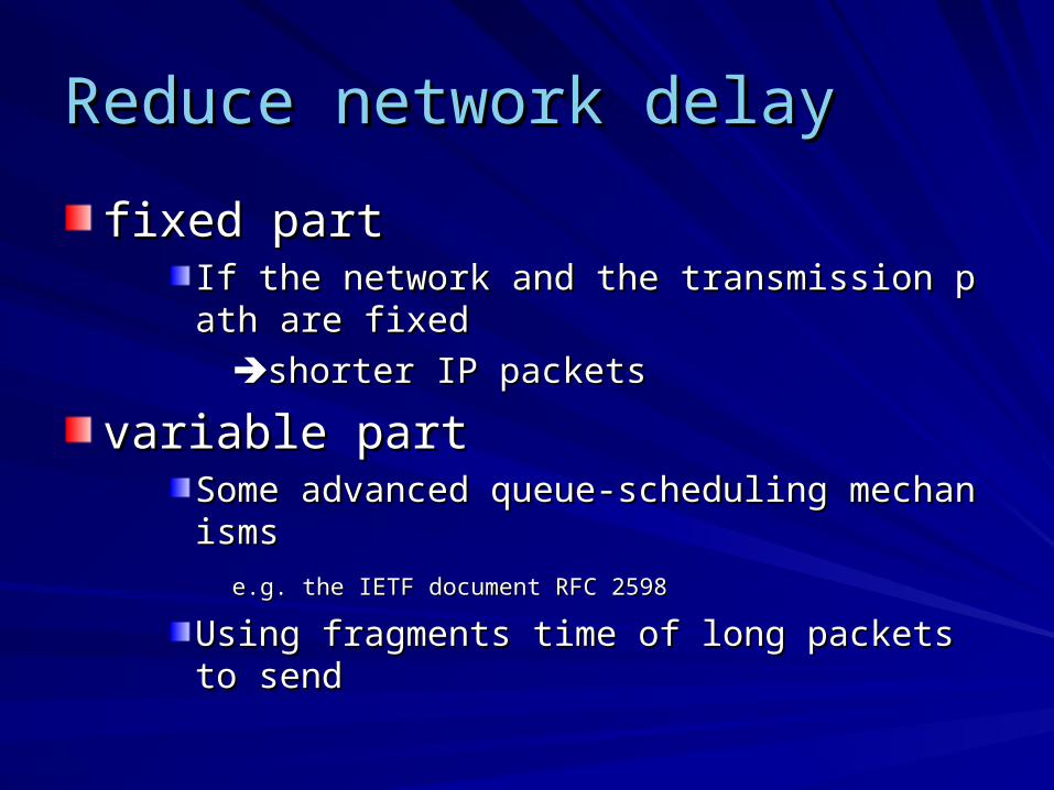
Reduce network delayReduce network delay
fixed part fixed part If the network and the transmission path are fixedIf the network and the transmission path are fixed
shorter IP packets shorter IP packets
variable partvariable partSome advanced queue-scheduling mechanisms Some advanced queue-scheduling mechanisms
e.g. the IETF document RFC 2598e.g. the IETF document RFC 2598
Using fragments time of long packets to sendUsing fragments time of long packets to send
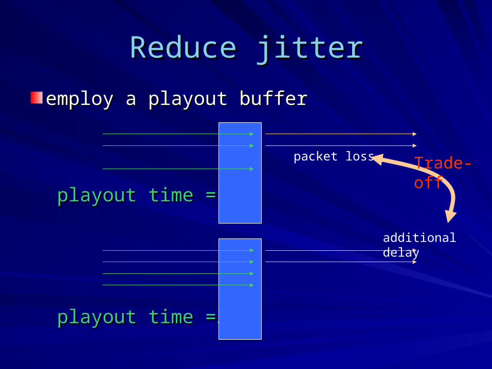
Reduce jitterReduce jitter
employ a playout buffer employ a playout buffer
playout time =1playout time =1
playout time =2playout time =2
packet loss
additional delay
Trade-off
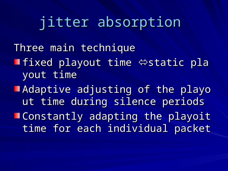
jitter absorption jitter absorption
Three main technique Three main technique
fixed playout time fixed playout time static playout timestatic playout time
Adaptive adjusting of the playout time duriAdaptive adjusting of the playout time during silence periods ng silence periods
Constantly adapting the playoit time for eaConstantly adapting the playoit time for each individual packet ch individual packet
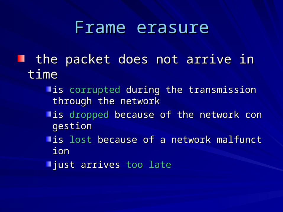
Frame erasureFrame erasure
the packet does not arrive in timethe packet does not arrive in timeis is corruptedcorrupted during the transmission through the ne during the transmission through the networktwork
is is droppeddropped because of the network congestion because of the network congestion
is is lostlost because of a network malfunction because of a network malfunction
just arrives just arrives too latetoo late

Reduce frame erasureReduce frame erasure
FEC (Forward Error Correction) FEC (Forward Error Correction) need additional bandwidth and increases delays beneed additional bandwidth and increases delays because additional processing. cause additional processing.
Loss concealment Loss concealment be used independently or in the combination with be used independently or in the combination with FEC FEC
is effective only at low loss rate of a single frame is effective only at low loss rate of a single frame
Out-of-order packet delayOut-of-order packet delay
occurs in the network with a complex occurs in the network with a complex topology topology
Done in the jitter bufferDone in the jitter bufferreordering (using RTP header)reordering (using RTP header)
elimination of jitter elimination of jitter