performance analysis of double cage induction motor with
TRANSCRIPT

Asım Gökhan YETGİN, https://orcid.org/0000-0003-3971-0504
ISSN Online: 1309-2243 http://dergipark.org.tr/makufebed
https://doi.org/10.29048/makufebed.755638
Mehmet Akif Ersoy Üniversitesi Fen Bilimleri Enstitüsü Dergisi 11(2): 176-188 (2020) The Journal of Graduate School of Natural and Applied Sciences of Mehmet Akif Ersoy University 11(2): 176-188 (2020)
Araştırma Makalesi / Research Paper
Performance Analysis of Double Cage Induction Motor with Broken Bar Faults in Outer Cage
Asım Gökhan YETGİN 1
1Burdur Mehmet Akif Ersoy University, Faculty of Engineering and Architecture, Burdur-Turkey
Geliş Tarihi (Received): 20.06.2020, Kabul Tarihi (Accepted): 14.08.2020
Sorumlu Yazar (Corresponding author): [email protected]
+90 248 2132778 +90 248 2132704
ABSTRACT Induction motors are one of the most commonly used motor in the industry. For this reason, a fault (electrical or mechanical) inside or outside of the motor can cause the motor to go out of power and even cause the production losses inside the factory. Although there are many studies on single-cage induction motor failures in the literature, double cage motor failures are not a frequent subject of study. Therefore, in this study, it was investigated how the outer cage slot faults in a double cage induction motor affect the motor performance. Analyses were performed using Finite Element Method (FEM). 1, 2, 3 and 4 outer cage broken bars in the rotor slot were investigated. Rotor currents, magnetic vector potential values, magnetic flux distributions, current densities, radial forces and torque-speed graphs of the motor models were obtained and compared for both healthy and failure motors. The results show that as the number of broken bar in the rotor increased, a significant reduction was observed in all three torque (starting, maxi-mum and nominal) values. It has been observed that the starting torque decreased by 13.77% for the 4 broken outer cage rotor bars motor according to the healthy motor. Keywords: Broken bars, finite element method, induction motor, outer rotor cage fault, performance analysis
Dış Kafesinde Kırık Bar Arızası Olan Çift Kafesli Asenkron Motorun Performans Analizi
ÖZ Asenkron motorlar endüstride en sık kullanılan motorlardan birisidir. Bu nedenle, motorun içinde veya dışında bir arıza (elektrik veya mekanik) motorun gücünün kesilmesine ve hatta fabrika içinde üretim kayıplarına neden olabilir. Literatürde tek kafesli asenkron motor arızaları üzerine çok sayıda çalışma olmasına rağmen, çift kafesli motor arıza-ları sıkça araştırılan bir konu değildir. Bu nedenle, bu çalışmada, çift kafesli bir asenkron motorun dış kafes oluğundaki hataların motor performansını nasıl etkilediği araştırılmıştır. Analizler Sonlu Elemanlar Yöntemi (SEY) kullanılarak yapılmıştır. Rotor oluğunda 1, 2, 3 ve 4 adet dış kafes kırığı olan motor modelleri incelenmiştir. Motor modellerinin rotor akımları, manyetik vektör potansiyel değerleri, manyetik akı dağılımları, akım yoğunlukları, radyal kuvvetler ve moment-hız grafikleri elde edilmiş ve hem sağlam hem de arızalı motorlar için karşılaştırılmıştır. Sonuçlar, rotordaki kırık çubuk sayısı arttıkça, her üç moment (yol alma, maksimum ve nominal) değerinde önemli bir azalma meydana geldiğini göstermiştir. Sağlam motora göre, rotor oluğunda 4 kırık bulunan motorun yol alma momentinin %13.77 oranında azaldığı görülmüştür.
Anahtar Kelimeler: Kırık çubuklar, sonlu elemanlar yöntemi, asenkron motor, dış rotor kafes arızası, performans
analizi

Yetgin 11(2): 176-188 (2020)
177
INTRODUCTION The three phase squirrel cage induction motor is now one of the most reliable, efficient and cost effective elec-tric machines which is the largest electrical energy con-sumer in the industry (Tudorache et al., 2006; Wang et al., 2018). Induction motors have many advantages thanks to their easy and robust construction. This type of machine is extensively used in many industrial appli-cations (Nakamura and Mizuno, 2013; Roubache et al., 2016; Brooks et al., 2018). In general, induction motors are manufactured in two ways with squirrel cage and wound rotor. Although the single cage structure in the industry is used more and more, the double cage rotor structure has a few applications (Lorenzani et al., 2012). Some of these applications can be given as follows: con-veyors, crushers, mixers, compressors, loaded pumps
and the likes (Gyftakis et al., 2012). The double cage ro-tor is an effective technique that improves the starting performance of induction motors (Yamamoto et al., 2017), which provides high starting torque and low start-ing current (Guru et al., 2013). Double cage rotors are characterized by the large outer (starting) bar resistance and large inner (running) bar leakage inductance, as shown in Figure 1. The high starting torque is obtained by confining the current to the high resistance outer cage during the startup transient at high slip when the induc-tive impedance is dominant over the resistive imped-ance as shown in Figure 1 (Lorenzani et al., 2012). In the figure, Vs is voltage, Is is stator current, Ir is rotor cur-rent, Rs is stator resistance, Xs is stator reactance, Xm is magnetization reactance, Rr1 and Xr1 are outer cage re-sistance and reactance, Rr2 and Xr2 are inner cage re-sistance and reactance, s is slip value and Im is magnet-ization current.
Figure 1. Induction motor double cage equivalent circuit
Double cage induction motors can be divided into two categories depending on the structure of the rotor cage. If both, the outer and the inner bar, are from the same material, they are short circuited to the same end-ring and the rotor has one cage, similar to the standard “A” class induction motor. On the other hand, if the two bars are from different materials, then the outer bars are short circuited independently from the inner bars and the rotor is manufactured with two cages. Usually, when two dif-ferent conducting materials are implemented into the ro-tor, the material of the greatest resistivity, forms the outer cage, in order to improve the motor's starting be-havior. Furthermore, since the cost of production in-creases with the double cage structure, special attention should be paid to the design process not only for the electromagnetic properties of these motors but also for their general behavior (thermal, vibration, etc.) and their reliability (Gyftakis et al., 2012). The flux distributions that occur during starting and operation of a double cage induction motor are given in Figure 2 (Jahic et al., 2015).
Figure 2. Magnetic flux in the double cage The geometries used in induction motors as double cages are given in Figure 3. It is seen that the outer and inner cage geometries are generally preferred for the cir-cle and rectangular slot types. In this study, the structure of Figure 3 (i) is used for the rotor slot geometry.

Performance Analysis of Double Cage Induction Motor with Broken Bar Faults in Outer Cage
178
Figure 3. Double cage geometries in different structures (Bernatt and Bernatt, 2013; Boughrara and Ibtiouen, 2014; Jahic et al., 2015; Preez, 2016; Yamamoto et al., 2017)
In the literature, it is seen that single cage rotor struc-tures are generally used for rotor fault analysis of three phase induction motors. These failures are usually 1, 2 or 3 broken rotor bars or end ring failures (Hamdani et al., 2008; Xie et al., 2012; Pezzani et al., 2014; Ishikawa, 2015; Xie et al., 2018; Yetgin, 2019). There are publica-tions in the form of comparison of faulty conditions and healthy motor, and there are a limited number of publi-cations related to double cage rotor faults. In Boughrara and Ibtiouen (2014) studies, they have pro-vided an analytical method for calculating the magnetic field distribution, electromagnetic performance and equivalent circuit parameters in the case of a healthy and broken rotor bar with double cage rotor induction motor. Munteanu et al. (2012) used a three phase induc-tion motor used in the mining industry to obtain the min-imum current and maximum torque using a double cage rotor slot structure. In the Daviu et al.’ (2011) paper, con-sidering that the influence of the faulty outer cage is strong at startup due to the large outer cage current, de-tection of outer cage faults under the startup transient is investigated. A Discrete Wavelet Transform-based method is proposed as a viable solution to detection of outer cage faults for double cage motors. The aim of Gyftakis’s (2013) paper is to compare and evaluate dif-ferent diagnostic tools for defining broken bar failure in delta connected double cage induction motors. The study is performed with FEM. Lorenzani et al. (2012), were derived and verified a dynamic model for double squirrel cage rotor induction motors with outer cage faults. It was shown in the paper that parameter identifi-cation is a critical part of the dynamic model. This is not a trivial or straightforward procedure for double cage ma-chines, and an accurate finite element analysis can be very helpful for representing parameters accurately un-der different operating conditions. In the Park et al.’ (2010) paper, the detectability of broken outer cage bars in double cage motors for the most commonly used rotor bar test methods is evaluated. A finite element and ex-perimental study show that the sensitivity of on-line mo-tor current signature analysis is significantly decreased,
whereas that of off-line standstill tests is not influenced for broken outer cage bars. In the Gritli et al.’ (2014) pa-per, a discrete wavelet transform-based method is pro-posed for the detection of outer cage faults in Double Cage Induction Motors (DCIMs) operating under transi-ent load conditions. An experimental study on a custom built copper double cage rotor shows that the proposed approach offers good diagnostic capability compared to the existing techniques for DCIMs used in speed-varying applications and solves some of the previous problems. In this study, the effects of broken bars on motor perfor-mance were investigated in detail by performing an anal-ysis of the outer cage faults which may occur in a double cage induction motor. Healthy motor and 1, 2, 3 and 4 outer cage broken bar motor models were analyzed with FEM. Magnetic vector potential, magnetic field, flux dis-tributions, inner and outer cage rotor currents, torque-speed graphs analysis were obtained for each motor model. In this study, it contributes to the literature be-cause it investigates the effects of double layer broken rotor bar failures on the motor instead of single layer bro-ken rotor bar failures, which is the subject of many stud-ies in the literature. Induction Motor Faults Induction motors are the most preferred electric motors in the industry due to their robust construction and not easy failure. However, for unexpected reasons, faults that may occur inside or outside of the motor prevent the operating efficiently. There are several methods for de-tecting faults that may occur in induction motors. Thanks to these methods, the motor can be deactivated without failure. Detection of motor faults in the initial phase is important because it leads to increased reliability and low failure time. Motor failure could not be determined in the first step can lead to disaster and induction motor can be se-riously damaged (Kathir et al., 2012). Induction motor faults are divided into electrical and mechanical faults.

Yetgin 11(2): 176-188 (2020)
179
General failures in inductions motors can be given as follows (Alsaedi, 2015; Huang et al., 2016):
Stator faults resulting in the opening or shorting of one or more of a stator phase winding.
Abnormal connection of the stator windings.
Shorted rotor field winding.
Broken rotor bar or cracked rotor end rings.
Eccentricity (Static and/or dynamic air gap irregu-larities).
Bent shaft.
Bearing and gearbox failures.
The percentage of failures in induction motor component is as follows (Alsaedi, 2015):
Bearing related faults: 40%
Stator winding faults: 38%
Rotor related faults: 10%
Other faults: 10% Rotor Bar Faults The broken bars cause, a strong dissymmetry of the magnetic field into machine air gap which creates the ro-tate flux harmonics. In this situation, the machine con-sumes a lot of reactive power and this becomes pres-ently dominant than the active power, which conducts to reduce the torque capabilities of the motor (Said, 2004). Cracked or broken rotor bars and end rings failure are common faults in the three phase squirrel cage induction motors. Generally, 1, 2, 3 or more broken rotor bar are generated in the rotor bars for the single cage induction motor (Pezzani et al., 2014; Ishikawa, 2015; Hamdani et al., 2008; Miceli et al., 2014; Gritli et al., 2013). This is shown in Figure 4.
Figure 4. Healthy rotor and rotors with one, two and three broken bars (Pezzani et al., 2014)
The temperature rise around the cracked bars may eventually break the bars and the electric arc occurs around the broken bars. This may damage the lamina-tions of the rotor body close to the broken bar region. The following reasons can lead to cracking or breakage of the rotor bars (Faiz et al., 2007):
Thermal stress due to over-load, non-uniform heat distribution, hot spot and arc.
Magnetic stresses due to electromagnetic forces, magnetic asymmetry forces, noises and electro-magnetic vibrations.
Residual stress from the fabrication process.
Dynamic stress due to rotor axial torque and cen-trifugal forces.
Circumferential stress due to wearing and pollution of rotor material by chemical materials and humid-ity.
Mechanical stress due to mechanical fatigue of dif-ferent parts, ball-bearing damage, loosens lamina-tions etc.
Rotor faults are caused by a combination of various stresses acting on the rotor. These stresses can be elec-tromagnetic, thermal, residual, dynamic, environmental and mechanical. However, induction motor rotor faults usually start from a small break in the rotor bar or from a high resistance point. When such a fault increases, the magnetic field becomes increasingly asymmetrical due to the absence of induced currents in the broken rotor bars. This leads to local saturation and disproportionate magnetic distribution in the stator and rotor teeth near the broken bars. The increase of high harmonic compo-nents can trigger several electromagnetic events, such as the development of inverse magnetic field, torque pulse, and unbalanced magnetic attraction. All these events are not desirable because they reduce the relia-bility of the induction motor. The resistance of the broken bars is very high compared to the value of the healthy rotor bars. This is very likely to cause disproportionate distribution of rotor currents. The parts of rotor currents that are not flowing in the broken bars due to high re-sistance flow in the bars next to the broken. This results

Performance Analysis of Double Cage Induction Motor with Broken Bar Faults in Outer Cage
180
in an increase in the value of these bars. Although the broken bar currents flow in adjacent bars, the sum of the rotor currents is lower than in the healthy rotor. Very high current density causes overheating in the bar (Vaimann and Kallaste, 2011). It can cause torque and speed fluc-tuations, noise and unstable stator currents, reduce av-erage torque (Maouche et al., 2014).
MATERIAL AND METHODS In recent years, finite element method has been used frequently in the analysis, simulation and modelling of electrical machines. The simulation results are sensitive to the quality of the Finite Element (FE) model, thus crit-ical parameters for FE model have to be specified care-fully (Han et al., 2010). In this study, finite element method was used for the analysis of the healthy motor and the outer cage broken bar motor. Finite element analysis is a computer based numerical technique for calculating the parameters of electromagnetic devices. It can be used to calculate the flux density, flux linkages, inductance etc. In the finite el-ement method, the large electromagnetic device is bro-ken down into many small elements. The equations de-scribing the behavior of the individual elements are joined into an extremely large set of equations that de-scribe the whole device. The computer can solve this large set of simultaneous equations. From the solution, the computer extracts the behavior of the individual ele-ments. Finite element methods of analysis have emerged in the past decades as the useful numerical methods for magnetic field analysis of electrical ma-chines (Sudar et al., 2012). Magnetic field waveform contains full information about the stator and rotor positions and mechanical parts of the motor. Distribution of the magnetic flux density (B) is calculated from the magnetic vector potential (A) as fol-lows in Equation (1) (Faiz and Ebrahimi, 2009).
B A (1)
In order to calculate the force in induction motors, a cir-cle must be formed in the middle of the air gap section.
These regions must be enclosed by air to get accurate results of the torque. The electromagnetic torque is com-puted by a volume integration of Maxwell’s stress tensor over the selected area. An average valued torque (or weighted torque) is calculated in the time-harmonic sim-ulations. The Maxwell’s stress tensor is used to calculate the radial air-gap forces (Fr) in Equation (2) (Wilow, 2014).
2 2
0
1
2r n tF B B
(2)
Where Bn and Bt are the radial and tangential compo-nents of the magnetic flux density, µ0 is the magnetic permeability of free space. The electromagnetic torque is determined by integration of T over the stator and rotor surface (Faiz and Ebrahimi, 2009). In Equation (3), r0 is the radius of the contour and l is the length.
0
0n t
r lT B B ds
(3)
The model of four outer cage broken bar motors used in this study and the mesh structure are given in Figure 5. 87393 nodes and 174625 elements are produced in the modeling. Aluminum material with an electrical conduc-tivity of 34.45 MS/m is used in the rotor slots (URL-1), magnetic material with permeability µx and µy values of 7000 is used in the stator and rotor core parts and in the shaft section. Analysis of electrical machines using the finite element method requires a closed model. For this reason, the outer diameter of the motor must be defined as zero (for boundary condition) in order to keep the magnetic fluxes in the motor. Since the full geometry is addressed in the modelling, the homogeneous Dirichlet boundary condition is defined at the stator outer bound-ary. FEM analyzes were performed in the Finite Element Method Magnetics (FEMM) program (Meeker, 2014). The motor has 24 stator slots and 18 double cage rotor slots. Motor voltage is 380 V, frequency is 50 Hz, rotor speed is 2850 rpm, the connection is star and the motor power is 800 W.

Yetgin 11(2): 176-188 (2020)
181
Figure 5. 4 outer cage broken bar motor model and mesh distribution
RESULTS AND DISCUSSION
In this section, the results of analysis of the faults of the outer cage of the induction motor with double cage struc-
ture and the effects on the motor performance are ex-plained. Table 1 includes the flux density at different lo-cations of the stator and of the rotor at nominal operating conditions (sn = 0.05) for healthy and 4 broken motor models.
Table 1. Average flux values in different regions for healthy and 4 broken bars motor models
Position Healthy [T] 4 broken bars [T] % Difference
Stator yoke 0.852 0.996 + 16.90140 Stator tooth 0.639 0.764 + 19.56181 Rotor yoke 0.650 0.801 + 23.23076 Rotor inner cage 0.639 0.735 + 15.02347 Rotor outer cage 0.934 0.995 + 6.531049
When the Table 1 is examined, the average magnetic flux density values of the 4 broken motors at the deter-mined points indicate that the values of the motor have increased significantly according to healthy motor. This situation explains that 4 broken motors have saturation at these points according to healthy motor and have a negative effect on motor performance. Figure 6 shows the magnetic flux distributions obtained from healthy and 4 broken motor models. The flux distri-butions of the healthy motor are given in Figure 6(a), and the 4 broken motor model is given in Figure 6(b). The
maximum flux density value obtained from the healthy motor is 1.68 T, while the value obtained from the 4 rotor bar broken motor is 1.92 T. In order to understand the difference between the magnetic flux densities given in the figure, the lower bound value of the scale is set to zero and the upper bound value is set to 1.95 T. When the figure is examined, it is seen that the flux density val-ues obtained from 4 broken motor models are higher. This figure also shows that the obtained results which consistent with the average flux density values in Table 1.

Performance Analysis of Double Cage Induction Motor with Broken Bar Faults in Outer Cage
182
Figure 6. Magnetic flux distributions a) healthy motor b) 4 broken motor
Figure 7 (a) and (b) show the current density distribution of healthy and 4 broken motor models respectively. Cur-rent density scale is taken the same for each model. Bro-ken rotor bars are shown as bars 3, 4, 5 and 6. The bro-ken bars are formed only in the outer cage of the rotor
slots. It is seen that the current density values in the in-ner cage bars in the slots with broken rotor bars in-crease.
Figure 7. Current density distribution a) healthy motor b) 4 broken motor The current density values for healthy and 4 broken mo-tor models are given in Figure 8. There is a balanced current density in the non-broken rotor bars and current density values are seen to increase gradually in broken
bars. This is due to the current accumulation in the bars around the broken rotor bars. In the healthy motor, more balanced current density values are obtained.

Yetgin 11(2): 176-188 (2020)
183
Figure 8. Current density graph for healthy and 4 broken bar motor (bar 1-8)
Figure 9 shows the change in average and maximum current values obtained from healthy and broken motor models. When the figure is examined, it is seen that as the number of broken rotor increases, there is an in-crease in the maximum current value according to the
healthy motor. Average current values were obtained close to each other.
Figure 9. Average and maximum rotor current graph The change in rotor currents in each rotor slot are shown in Figure 10. It is seen that the currents change in an unbalanced manner in the broken rotor parts. In the other parts, it is seen that the currents are obtained close to each other. It is seen that the currents in the broken bars 3, 4, 5 and 6 show differences, and the flows are affected by the broken structure in the slots on the right and left sides of the broken bars. Other rotor bars have a balanced current distribution.
The simulated results of the rotor current magnitude for each inner and outer cage bar for a faulty rotor with 4 broken outer bars are shown in Figure 11. While the cur-rent values of the broken rotor bars are zero, it is seen that there is a large increase in the current values in the inner cage of the same bar.
6
7
8
9
10
Bar 1 Bar 2 Bar 3 Bar 4 Bar 5 Bar 6 Bar 7 Bar 8
(1Broken)
(2Broken)
(3Broken)
(4Broken)
Cu
rren
t D
ensi
ty [
MA
/m2
]
4 Broken Motor
Healthy Motor
480
490
500
510
520
530
540
550
560
Healthy 1 Broken 2 Broken 3 Broken 4 Broken
Ave
rage
an
d M
axim
um
Cu
rren
t [A
]
Average Current
Maximum Current

Performance Analysis of Double Cage Induction Motor with Broken Bar Faults in Outer Cage
184
Figure 10. Rotor current graph
Figure 11. Inner and outer cage rotor current graph
Figure 12 shows the variation of the magnetic vector po-tential occurring in the air gap of the induction motor. In the section where the broken bars are deformed, the re-sults obtained in the other parts seem to be equal. This situation also affects the flux distribution negatively.
Figure 13 presents the magnetic flux distributions in the air gap obtained from healthy motor and broken motor models. When the shape is examined, it is seen that the flux density values change in the broken parts.
0
100
200
300
400
500
600
1 2 3 4 5 6 7 8 9 10 11 12 13 14 15 16 17 18
Ro
tor
Cu
rren
t [A
]
Number of Rotor SlotHealthy 1 Broken 2 Broken 3 Broken 4 Broken
Broken Bars
0
100
200
300
400
500
1 2 3 4 5 6 7 8 9 10 11 12 13 14 15 16 17 18
Ro
tor
Bar
Cu
rren
t [A
]
Number of Rotor Bar
Inner Rotor Bar Outer Rotor Bar
4 Broken Bars

Yetgin 11(2): 176-188 (2020)
185
Figure 12. Magnetic vector potential graph
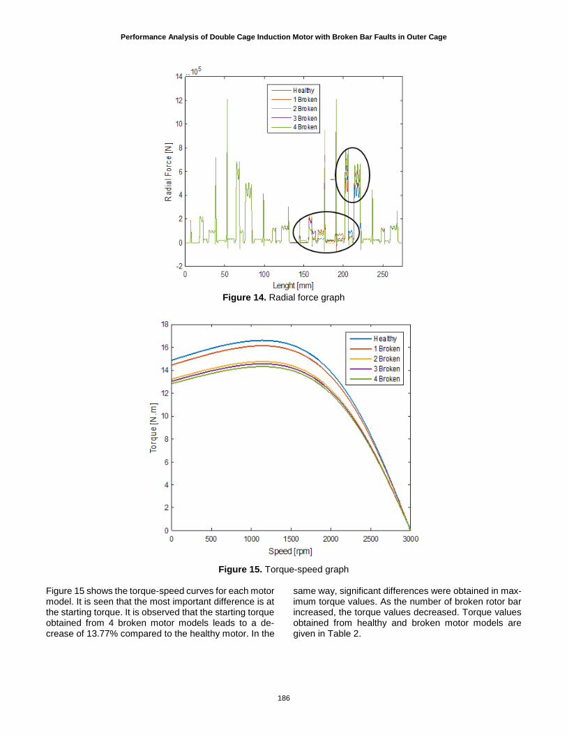
Figure 13. Magnetic flux distribution graph The forces obtained in the radial direction is given in Fig-ure 14. Variations in magnetic vector potential and B val-ues caused an increase in radial force values. This situ-ation indicates that the broken areas are exposed to
more force and this increases the probability of breaking in broken bars.
Performance Analysis of Double Cage Induction Motor with Broken Bar Faults in Outer Cage
186
Figure 14. Radial force graph
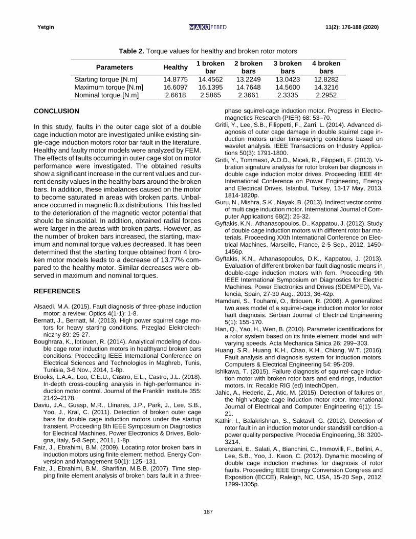
Figure 15. Torque-speed graph
Figure 15 shows the torque-speed curves for each motor model. It is seen that the most important difference is at the starting torque. It is observed that the starting torque obtained from 4 broken motor models leads to a de-crease of 13.77% compared to the healthy motor. In the
same way, significant differences were obtained in max-imum torque values. As the number of broken rotor bar increased, the torque values decreased. Torque values obtained from healthy and broken motor models are given in Table 2.
Yetgin 11(2): 176-188 (2020)
187
Table 2. Torque values for healthy and broken rotor motors
Parameters Healthy 1 broken
bar 2 broken
bars 3 broken
bars 4 broken
bars
Starting torque [N.m] 14.8775 14.4562 13.2249 13.0423 12.8282 Maximum torque [N.m] 16.6097 16.1395 14.7648 14.5600 14.3216 Nominal torque [N.m] 2.6618 2.5865 2.3661 2.3335 2.2952
CONCLUSION In this study, faults in the outer cage slot of a double cage induction motor are investigated unlike existing sin-gle-cage induction motors rotor bar fault in the literature. Healthy and faulty motor models were analyzed by FEM. The effects of faults occurring in outer cage slot on motor performance were investigated. The obtained results show a significant increase in the current values and cur-rent density values in the healthy bars around the broken bars. In addition, these imbalances caused on the motor to become saturated in areas with broken parts. Unbal-ance occurred in magnetic flux distributions. This has led to the deterioration of the magnetic vector potential that should be sinusoidal. In addition, obtained radial forces were larger in the areas with broken parts. However, as the number of broken bars increased, the starting, max-imum and nominal torque values decreased. It has been determined that the starting torque obtained from 4 bro-ken motor models leads to a decrease of 13.77% com-pared to the healthy motor. Similar decreases were ob-served in maximum and nominal torques. REFERENCES Alsaedi, M.A. (2015). Fault diagnosis of three-phase induction
motor: a review. Optics 4(1-1): 1-8. Bernatt, J., Bernatt, M. (2013). High power squirrel cage mo-
tors for heavy starting conditions. Przeglad Elektrotech-niczny 89: 25-27.
Boughrara, K., Ibtiouen, R. (2014). Analytical modeling of dou-ble cage rotor induction motors in healthyand broken bars conditions. Proceeding IEEE International Conference on Electrical Sciences and Technologies in Maghreb, Tunis, Tunisia, 3-6 Nov., 2014, 1-8p.
Brooks, L.A.A., Loo, C.E.U., Castro, E.L., Castro, J.L. (2018). In-depth cross-coupling analysis in high-performance in-duction motor control. Journal of the Franklin Institute 355: 2142–2178.
Daviu, J.A., Guasp, M.R., Llinares, J.P., Park, J., Lee, S.B., Yoo, J., Kral, C. (2011). Detection of broken outer cage bars for double cage induction motors under the startup transient. Proceeding 8th IEEE Symposium on Diagnostics for Electrical Machines, Power Electronics & Drives, Bolo-gna, Italy, 5-8 Sept., 2011, 1-8p.
Faiz, J., Ebrahimi, B.M. (2009). Locating rotor broken bars in induction motors using finite element method. Energy Con-version and Management 50(1): 125–131.
Faiz, J., Ebrahimi, B.M., Sharifian, M.B.B. (2007). Time step-ping finite element analysis of broken bars fault in a three-
phase squirrel-cage induction motor. Progress in Electro-magnetics Research (PIER) 68: 53–70.
Gritli, Y., Lee, S.B., Filippetti, F., Zarri, L. (2014). Advanced di-agnosis of outer cage damage in double squirrel cage in-duction motors under time-varying conditions based on wavelet analysis. IEEE Transactions on Industry Applica-tions 50(3): 1791-1800.
Gritli, Y., Tommaso, A.O.D., Miceli, R., Filippetti, F. (2013). Vi-bration signature analysis for rotor broken bar diagnosis in double cage induction motor drives. Proceeding IEEE 4th International Conference on Power Engineering, Energy and Electrical Drives. Istanbul, Turkey, 13-17 May, 2013, 1814-1820p.
Guru, N., Mishra, S.K., Nayak, B. (2013). Indirect vector control of multi cage induction motor. International Journal of Com-puter Applications 68(2): 25-32.
Gyftakis, K.N., Athanasopoulos, D., Kappatou, J. (2012). Study of double cage induction motors with different rotor bar ma-terials. Proceeding XXth International Conference on Elec-trical Machines, Marseille, France, 2-5 Sep., 2012, 1450-1456p.
Gyftakis, K.N., Athanasopoulos, D.K., Kappatou, J. (2013). Evaluation of different broken bar fault diagnostic means in double-cage induction motors with fem. Proceeding 9th IEEE International Symposium on Diagnostics for Electric Machines, Power Electronics and Drives (SDEMPED), Va-lencia, Spain, 27-30 Aug., 2013, 36-42p.
Hamdani, S., Touhami, O., Ibtiouen, R. (2008). A generalized two axes model of a squirrel-cage induction motor for rotor fault diagnosis. Serbian Journal of Electrical Engineering 5(1): 155-170.
Han, Q., Yao, H., Wen, B. (2010). Parameter identifications for a rotor system based on its finite element model and with varying speeds. Acta Mechanica Sinica 26: 299–303.
Huang, S.R., Huang, K.H., Chao, K.H., Chiang, W.T. (2016). Fault analysis and diagnosis system for induction motors. Computers & Electrical Engineering 54: 95-209.
Ishikawa, T. (2015). Failure diagnosis of squirrel-cage induc-tion motor with broken rotor bars and end rings, induction motors. In: Recalde RIG (ed) IntechOpen.
Jahic, A., Hederic, Z., Atic, M. (2015). Detection of failures on the high-voltage cage induction motor rotor. International Journal of Electrical and Computer Engineering 6(1): 15-21.
Kathir, I., Balakrishnan, S., Saktavil, G. (2012). Detection of rotor fault in an induction motor under standstill condition-a power quality perspective. Procedia Engineering, 38: 3200-3214.
Lorenzani, E., Salati, A., Bianchini, C., Immovilli, F., Bellini, A., Lee, S.B., Yoo, J., Kwon, C. (2012). Dynamic modeling of double cage induction machines for diagnosis of rotor faults. Proceeding IEEE Energy Conversion Congress and Exposition (ECCE), Raleigh, NC, USA, 15-20 Sep., 2012, 1299-1305p.

Performance Analysis of Double Cage Induction Motor with Broken Bar Faults in Outer Cage
188
Maouche, Y., Oumaamar, M.E.K., Boucherma, M., Khezzar, A. (2014). A new approach for broken bar fault detection in three-phase induction motor using instantaneous power monitoring under low slip range. International Journal of Electrical and Computer Engineering 4(1): 52-63.
Meeker, D. (2014). Induction motor example. 1-13. Miceli, R., Gritli, Y., Tommaso, A.D., Filippetti, F., Rossi, C.
(2014). Vibration signature analysis for monitoring rotor broken bar in double squirrel cage induction motors based on wavelet analysis. The International Journal for Compu-tation and Mathematics in Electrical and Electronic Engi-neering 33(5): 1625-1641.
Munteanu, A., Simion, A., Livadaru, L., Virlan, B., Şandru, M. (2012). Three phase squirrel-cage induction motor optimi-zation using finit element method. Proceeding IEEE Inter-national Conference and Exposition on Electrical and Power Engineering (EPE), Iasi, Romania, 25-27 Oct., 2012, 464-467p.
Nakamura, H., Mizuno, Y. (2013). Probabilistic diagnosis of short-circuit faults and insulation deterioration of stator winding of motor. Electrical Engineering in Japan 184(1): 30-41.
Park, J., Kim, B., Yang, J., Lee, S.B., Wiedenbrug, E.J., Teska, M., Han, S. (2010). Evaluation of the detectability of broken rotor bars for double squirrel cage rotor induction motors. Proceeding IEEE Energy Conversion Congress and Expo-sition, Atlanta, GA, USA, 12-16 Sep., 2010, 2493-2500p.
Pezzani, C., Donolo, P., Bossio, G., Donolo, M., Guzman, A., Zocholl, S.E. (2014). Detecting broken rotor bars with zero-setting protection. IEEE Transactions on Industry Applica-tions 50(2): 1373–1384.
Preez, H.D.C. (2016). Induction motor rotor bars. Electric-ity+Control, pp. 1-4. [Online available]: https://www.crown.co.za/images/magazines/electricity-control/SpotOn/Induction_motor_rotor_bars.pdf
Roubache, L., Boughrara, K., Ibtiouen, R. (2016). Analytical electromagnetic analysis of multi-phases cage rotor induc-tion motors in healthy, broken bars and open phases con-ditions. Progress In Electromagnetics Research (PIER) B 70: 13–130.
Said, N.N. (2004). Rotor resistance estimation of an induction motor to detect broken bars fault using h-h method. Electric Power Components and Systems 32(2): 149-161.
Sudar, V.A., Nagarajan, S., Rama, R.S. (2012). Detection and analysis of broken bar in three phase squirrel cage induc-tion motor using fem. Proceeding IEEE International Con-ference on Computing, Electronics and Electrical Technol-ogies (ICCEET), Kumaracoil, India, 21-22 Mar., 2012, 40-50p.
Tudorache, T., Taras, P., Fireteanu, V. (2006). Finite element diagnosis of squirrel cage induction motors with rotor bar faults. Proceeding 10th International Conference on Opti-mization of Electrical and Electronic Equipment (OPTIM), Brasov, Romania, 18–19 May, 2006, 1–6p.
URL-1 (2019). http://www.femm.info/wiki/InductionMotorEx-ample (Online access: 25/12/2019).
Vaimann, T., Kallaste, A. (2011). Detection of broken rotor bars in three-phase squirrel-cage induction motor using fast fou-rier transform. Proceeding 10th International Symposium, Topical Problems in the Field of Electrical and Power Engi-neering, Parnu, Estonia, 10-15 Jan., 2011, 52-56p.
Wang, P.P., Chen, X.X., Zhang, Y., Hu, Y.J., Miao, C.X. (2018). IBPSO‑based music algorithm for broken rotor bars fault detection of induction motors. Chinese Journal of Me-chanical Engineering 31: 1-10.
Wilow, V. (2014). Electromagnetical model of an induction mo-tor in COMSOL Multiphysics. Master Thesis, Royal Insti-tute of Technology, Stockholm.
Xie, Y., Gu, C., Cao, W. (2012). Study of broken bars in three-phase squirrel-cage induction motors at standstill. Euro-pean Transactions on Electrical Power 2012: 1-15.
Xie, Y., Guo, J., Chen, P., Li, Z. (2018). Coupled fluid-thermal analysis for induction motors with broken bars operating under the rated load. Energies 11(8): 1-17.
Yamamoto, S., Hirahara, H., Tanaka, A., Ara, T. (2017). A sim-ple method for determining equivalent circuit parameters of double-cage induction motors from no-load and locked ro-tor tests. Proceeding IEEE Energy Conversion Congress and Exposition (ECCE), Cincinnati, OH, USA, 1-5 Oct., 2017, 301-306p.
Yetgin, A.G. (2019). Effects of induction motor end ring faults on motor performance, experimental results. Engineering Failure Analysis 96: 374-383.