performance analysis of video transmission over ieee 802...
TRANSCRIPT

2346 IEEE TRANSACTIONS ON VEHICULAR TECHNOLOGY, VOL. 56, NO. 4, JULY 2007
Performance Analysis of Video Transmission OverIEEE 802.11a/e WLANs
Sai Shankar N, Senior Member, IEEE, and Mihaela van der Schaar, Senior Member, IEEE
Abstract—This paper presents efficient mechanisms for delay-sensitive transmission of video over IEEE 802.11a/e Wireless LocalArea Networks (WLANs). Transmitting video over WLANs in realtime is very challenging due to the time-varying wireless channeland video content characteristics. This paper provides a com-prehensive view of how to adapt the quality of service signaling,IEEE 802.11e parameters and cross-layer design to optimize thevideo quality at the receiver. We propose an integrated systemview of admission control and scheduling for both contentionand poll-based access of IEEE 802.11e Medium Access Control(MAC) protocol and outline the merits of each approach for videotransmission. We also show the benefits of using a cross-layeroptimization by sharing the Application, MAC, and Physicallayer parameters of the Open Systems Interconnection stack toenhance the video quality. We will show through analysis andsimulation that controlling the contention-based access in IEEE802.11e is simple to realize in real products and how differentcross-layer strategies used in poll-based access lead to a largernumber of stations being simultaneously admitted and/or a highervideo quality for the admitted stations. Finally, we introduce anew concept called time fairness, which is critical in enhancingthe video performance when different transmitter–receiver pairsdeploy different cross-layer strategies.
Index Terms—Algorithm, cross-layer optimization, IEEE802.11e Wireless Local Area Networks (WLANs), scheduler,video.
I. INTRODUCTION
W IRELESS multimedia transmission across WirelessLocal Area Networks (WLANs) has been gaining at-
tention in the recent years because of the proliferation oftechnologies like Bluetooth, IEEE 802.11, 3G, and WiMAX.In particular, IEEE 802.11 WLAN [1] has emerged as a prevail-ing technology for (indoor) broadband wireless access becauseit supports real-time conversational multimedia applicationslike Voice over Internet Protocol and video conferencing. Sincethese applications are very delay sensitive (delays of around200 ms are imposed), they require quality of service (QoS)support from the lower layers of the Open Systems Inter-connection (OSI) stack to ensure timely delivery as well asto divide the available wireless resources in a fair manneramong competing wireless stations (WSTAs). Several require-
Manuscript received August 15, 2005; revised June 14, 2006 and July 28,2006. The review of this paper was coordinated by Dr. W. Zhuang.
S. Shankar N is with the Corporation R&D Systems Engineering Depart-ment, Qualcomm Inc., San Diego, CA 92121 USA (e-mail: [email protected]).
M. van der Schaar is with the Electrical Engineering Department, Universityof California at Los Angeles, Los Angeles, CA 90095 USA (e-mail: [email protected]).
Color versions of one or more of the figures in this paper are available onlineat http://ieeexplore.ieee.org.
Digital Object Identifier 10.1109/TVT.2007.897646
ments have to be addressed to provide successful interactivemultimedia applications over a network originally designedfor generic data traffic and characterized by potentially higherror rates. Multimedia data require a completely differentnetwork behavior: Throughput is no longer the only parameterin measuring network performance, and packet losses can be tosome extent tolerated if counterbalanced by timely packet de-livery. Multimedia communications have strictly bounded QoSrequirements in terms of packet losses, end to end delays, andjitter. For example, video conferencing requires an end-to-enddelay not greater than 200 ms, thus heavily restricting the pos-sibility to retransmit lost or corrupted packets. Existing IEEE802.11 standards, however, do not provide the necessary QoS tosupport such applications as they are aimed at solely replacingthe wired Ethernet, which supports only a best-effort service(not guaranteeing any service level to users/applications). Inorder to address multimedia support over WLAN, the IEEE802.11 Working Group defined a new supplement to supportQoS known as 802.11e [2].
The new 802.11e Medium Access Control (MAC) enablesapplications like voice, video, and bandwidth intense data ser-vices. With the advent of IEEE 802.11e, the application (APP)layer has to pass on the parameters to the IEEE 802.11e MACsuch that it can reserve adequate resources for the applicationto guarantee its bandwidth. Once the APP layer parameters aresignaled to the MAC layer, the IEEE 802.11e standard usesthe Traffic Specification (TSPEC) element to negotiate withthe QoS access point (QAP). The new MAC protocol of IEEE802.11e is called the Hybrid Coordination Function (HCF). TheHCF is called “hybrid” since it combines a contention channelaccess mechanism, which is referred to as enhanced distributedchannel access (EDCA), and a polling-based channel accessmechanism, which is referred to as HCF controlled channelaccess (HCCA), each of which operates simultaneously andcontinuously within the QoS basic service set (QBSS). The listof abbreviations and symbols used in this paper are shown inTables I and II, respectively.
A. Related Work in Multimedia Transmission andContributions of This Paper
Previous works on multimedia transmission over WLANsconsidered different layers in isolation or made assumptionson different layers when considering the optimization from aone-layer perspective. An excellent review of channel-adaptivemultimedia streaming research and error concealment strategiesis provided in [8]. Potential solutions for robust wireless mul-timedia transmission over error-prone networks include APP-layer packetization, (rate distortion optimized) scheduling, joint
0018-9545/$25.00 © 2007 IEEE

SHANKAR N AND VAN DER SCHAAR: ANALYSIS OF VIDEO TRANSMISSION OVER IEEE 802.11a/e WLANs 2347
TABLE ILIST OF ABBREVIATIONS
TABLE IILIST OF SYMBOLS
source-channel coding, error resilience, and error concealmentmechanisms [9]. In [6] and [7], a QoS framework has beenproposed that maps categorized video packets onto the relativedifferentiated service provided by the wireless channel usinga predetermined pricing model. Video categorization is basedon the relative priority index, which represents the relativepreference per packet in terms of loss and delay. At the Physical(PHY) and MAC layers, significant gains have been reportedby adopting a cross-layer optimization, such as link adaptation,channel aware scheduling, and optimal power control [10].However, these contributions are aimed at improving thethroughput or reducing power consumption without taking intoconsideration the multimedia content and traffic characteristics.
Explicit consideration of multimedia characteristics andrequirements can further enhance the important advancesachieved in cross-layer design at the lower layers. Possiblesolutions and architectures for cross-layer optimized multime-dia transmission have been proposed in [3]–[5]. Ansel et al.[11] proposed a scheduling scheme for IEEE 802.11e toimprove the performance of multimedia in terms of delay andloss. The paper shows that the fixed transmission opportunity(TXOP) allocation is not efficient for video transmission as itdoes not consider the bursty characteristics of video traffic, andthey propose improved scheduling schemes to alleviate thisproblem. In this paper, we shape the traffic that is arriving at theMAC buffer through a twin leaky bucket scheme that removesthe burstiness of the video traffic and ensures that a simplescheduler can be deployed for efficient video transmission.
This paper proposes a new integrated system design formultimedia transfer over IEEE 802.11e WLAN using bothEDCA and HCCA, where the admission control unit (ACU)and the scheduler are colocated with the QAP. We discussall aspects of multimedia transmission, including admissioncontrol and scheduling at the MAC layer and an optimal cross-layer algorithm using APP/MAC and PHY layers to enhancethe quality of video. The admission control and schedulingalgorithm is based on the concept of effective bandwidth thatuses the concept of statistical multiplexing in the wirelesschannel by admitting streams in a optimal way and ensurescomplete QoS for the admitted stream. This is different fromthe admission control proposed in the IEEE 802.11e standard[2] that is based on just mean or peak data rate allocation.The admission control based on mean data rate admits morestreams, as compared to our scheme that is based on effectivebandwidth, but it fails to satisfy the QoS demanded by theAPP. The peak data rate scheme, however, admits less streamscompared to our scheme, thus wasting wireless channel re-sources. Wireless channel characteristics change over time dueto fading, and any design of admission control must take thatinto account. To incorporate channel fading, we include a newparameter called channel burstiness (δ) that captures the first-order characteristics of time-varying wireless channel capacity.This paper will also discuss a new concept of air or time fairness[12] and shows how this can enhance the video quality in theWLAN network. We also explain a cross-layer algorithm thatis performed at the MAC layer considering different tradeoffsat the APP and PHY layers.
B. Motivation for Time Fairness
IEEE 802.11e can operate at multiple rates. The MACchooses a particular physical transmission rate that is based onthe experienced channel condition to satisfy the QoS neededby the real-time video streaming APP. This algorithm is calledlink adaptation [24], and it improves the station’s throughput,but also it causes unfairness to the WSTAs that have high trans-mission rates. This unfairness arises due to the fact that a frameof size L takes more transmission time at lower physical trans-mission rate and, hence, reduces the overall network throughputand increases the delay of the higher physical transmissionrate stations. To illustrate with a simple example, consider two

2348 IEEE TRANSACTIONS ON VEHICULAR TECHNOLOGY, VOL. 56, NO. 4, JULY 2007
Fig. 1. TSPEC element format.
Fig. 2. Token bucket policer and the arrival curves. (a) Token bucket representation of admission control. (b) Arrival curve and calculation of guaranteed rate.
WSTAs transmitting a 1000-bit frame at 11 and 1 Mb/s, respec-tively. The WSTA with 11 Mb/s takes 111.11 µs to transmit theframe, whereas the WSTA with 1-Mb/s rate takes 1 ms to trans-mit the same frame. As a result, the TXOP of the WSTA with11 Mb/s is deferred resulting in a degraded system throughputover a finite interval of measurement (t1, t2). As a remedy tothis unfairness, we propose a new concept called air fairness.
C. Organization of This Paper
The rest of this paper is organized as follows. Section II ex-plains the admission control based on effective (or guaranteed)bandwidth that also includes the channel burstiness and the sim-ple scheduling algorithm that was implemented in our HCCAmodel of IEEE 802.11e. Then, we explain how to guarantee theairtime usage of a stream/WSTA using EDCA by controllingthe parameters TXOP and CWmin in Section III. Section IVoutlines how the prioritized multimedia bitstreams (e.g., scal-able video) can be efficiently mapped onto the 802.11e HCCAparameters to ensure an improved quality in terms of individualstation performance as well as the overall system performance(i.e., more admitted station). Then, we outline a simple cross-layer strategy in Section V that could enhance the quality ofmultimedia by considering a small set of control parametersin APP, MAC, and PHY layers of the IEEE 802.11e system.IEEE 802.11 has multiple transmission rates depending onthe location of an individual station. This has large effectson the video quality not only to this station but also for theentire network. Section VI explains the essence of time or airfairness and shows how it improves the quality of multimediain these multirate or error environments. Section VII gives theconclusions and outlines necessary future research.
II. AIRTIME ADMISSION CONTROL AND SCHEDULING
IN IEEE 802.11e HCCA
Admission control is one of the most essential componentsin IEEE 802.11e. We will outline the admission control and the
scheduling scheme that will provide per flow QoS for multime-dia. To ensure user satisfaction, it is essential that a video streamonce admitted by HC has guaranteed its QoS for the lifetime ofthat stream. Thus, there is a need to control how many streamsare admitted into the system. The APP passes its request in formof the rate parameters to the MAC layer. The rate parametersthat were demanded by the APP are then translated into timeparameters by the MAC layer, and then, the HC (with the helpof ACU) colocated at the QAP makes a decision to admit orreject a stream. Thus, the APP layer parameters are signaledto the MAC layer in form of a TSPEC element. The TSPECelement contains the set of parameters that characterize thetraffic stream that the WSTA wishes to establish with the HC.Once the TSPEC request is received by the HC, it analyzes theTSPEC parameters and decides whether to admit the streaminto the network using the admission control algorithm ornot. The important TSPEC parameters of IEEE 802.11e areshown in Fig. 1. If the stream is admitted, the HC schedulesthe delivery of downlink traffic and/or QoS CF-Polls in orderto satisfy the QoS requirements of the stream, as specifiedin the TSPEC. Among the parameters defined in the TSPECelement of IEEE 802.11e, we use a subset of the parametersto design the efficient admission control. These parameters arepeak data rate (P ), mean data rate (r), maximum burst size (σ),delay (d), nominal MAC service data unit (MSDU) size (L),minimum PHY TX rate (R), and maximum MSDU size (M =2304 B). We also use the channel or link state to determinethe additional percentage of channel resources (bandwidth ortime) that need to be reserved to cover the losses that may occurin the wireless medium. The peak data rate, mean data rate,and the maximum burst size are part of the twin token bucketparameters that are supplied by the higher layer entities to theMAC. When the APP does not provide these parameters, theMAC needs to infer them over small intervals and pass themto the ACU colocated with the HC at QAP. Fig. 2 shows thetwin token bucket policer and the calculation of effective orguaranteed rate.

SHANKAR N AND VAN DER SCHAAR: ANALYSIS OF VIDEO TRANSMISSION OVER IEEE 802.11a/e WLANs 2349
To facilitate the efficient QoS support for multimedia ap-plications over wireless networks, it is essential to model awireless channel in terms of connection-level QoS metrics suchas data rate, delay, and delay-violation probability. However,the existing wireless channel models, i.e., PHY layer channelmodels, do not explicitly characterize a wireless channel interms of these QoS metrics. One of the earliest models tocharacterize wireless channels was reported in [17], whereinthey try to fit the parameters of the two-state Markov chainusing the parameters of Rayleigh or Riceian fading. In [18],a link-layer channel model that is termed as effective capacity(EC) has been developed. The key advantages of the EC link-layer modeling and estimation are ease of translation into QoSguarantees, such as delay bounds, simplicity of implementa-tion, and accuracy, and, hence, efficiency in admission controland resource reservation. Apart from the above approxima-tions found in the literature, we consider a simple approachto characterize the fading occurring in the wireless channel.This is termed as transmission burstiness δ. The transmissionburstiness represents the shortage of bits that were not served bythe wireless channel during a time interval [0, t]. As an example,if C is the original channel capacity of the wireless medium,then in any time interval [0, t], the maximum amount of bits thatcan be transmitted is C × t. However, due to interference andmobility, this channel may not be available for a short amountof time, and the amount of bits transmitted in time [0, t] isless than or equal to C × t. Let δ represent the total amountof bits wasted because of channel fading. This is obtained bydetermining the times when the channel is not usable in thetime interval of [0, t] and then multiplying this time by thechannel capacity C. Hence, in any time t the lower boundon the channel capacity available to that stream or WSTA isC × t− δ. This will be taken into consideration when modelingadmission control to admit multimedia. The value of δ canbe easily calculated by obtaining the mean of the channelfading that follows a particular distribution such as Rayleighor Riceian.
We need to evaluate the effective bandwidth of the streamthat is regulated by the first and second token bucket shown inFig. 2 (see [15] for further details). This method of calculatingthe effective bandwidth is different from the previous worksthat were based on the mean and the peak data rate [2].The mean-data-rate-based admission admits more streams atthe expense of QoS, and the peak-data-rate-based admissionprovides QoS at the expense of number of streams admitted.Our effective bandwidth-based stream based on twin tokenbucket is optimal as it exploits the statistical multiplexing ofall streams in the wireless channel without compromising theQoS requests of the admitted streams. Based on the twin leakybucket analysis and including the frame error rate into thesystem, we get the effective bandwidth as
gi =Pi[
1 + diPi−ρi
σi+δi
][1 − pe]
. (1)
The previous effective bandwidth computation does not in-clude overheads. Let us assume that for a stream i, the nominalMSDU size is Li. For each frame, there is an overhead in
time based on the acknowledgement (ACK) policy, interframespace (IFS) time, PHY layer convergence procedure preamble(PLCPPreamble), MAC and PHY layer headers, and pollingoverhead (only in case of upstream or sidestream). The schedul-ing policy also determines the polling overheads, as differentscheduling policies determine how many times one has to polla WSTA in the service interval denoted as SI. The value of theSI will be derived later. Assuming that the SI is known, thenumber of MSDUs per SI is given by
Ni =⌈gi ∗ SILi
⌉(2)
and the new guaranteed rate that is required for this connection,including overheads, is given by
g′i =Ni(Li + Oi)
SI(3)
where Oi in the above equation represents the overheads addedfor transmitting a frame. Now, the admission control policy,including the overheads, is given by the following equation:
g′i+1 +i∑
k=1
g′k ≤ C (4)
where g′i+1 is the guaranteed rate or effective bandwidth,including the overheads. Since the HC will poll (up-stream/sidestream) or access the medium (downstream) for aspecific time, the above rate parameters have to be converted totime parameter. We will convert the rate-based requirements ofthe stream given in (1) into the corresponding airtime require-ment based on the minimum PHY TX rate parameter. Duringthe admission control negotiation, the ACU and the QSTA/QAPnegotiate this parameter as to what is the minimum PHY TXrate that a WSTA and QAP/WSTA shall communicate. Theactual PHY rate can exceed the minimum PHY rate. If the rateof the source station (either QAP or WSTA) drops below theminimum PHY TX rate, the stream is considered to violateits initially negotiated QoS requirements and may be droppedby the ACU depending on the channel conditions. Thus, thesufficient condition for the minimum PHY TX rate is
Ri ≥ g′i. (5)
Based on the above guaranteed rate, the ACU determines thenumber of frames that arrive in the SI for stream i, assumingthat there are i− 1 streams already undergoing service inthe QBSS
NSIi =
⌈SI ∗ g′iLi
⌉. (6)
Then, the ACU calculates the TXOPs that are required toservice all these MSDUs in an SI. This is given by
TXOPi = NSIi ∗
(Li
Ri+ T overhead
i
)(7)

2350 IEEE TRANSACTIONS ON VEHICULAR TECHNOLOGY, VOL. 56, NO. 4, JULY 2007
Fig. 3. Schedule allocation for stream from WSTA “I” and schedule allocations for streams from WSTAs “I” to “k.”
where T overheadi is the overhead in time incurred per
frame transmission. The admission control algorithm can berewritten as
TXOPi
SI+
i−1∑k=1
TXOPk
SI≤ T − TCP
T(8)
where T is the beacon interval, and TCP is the time reserved forEDCA traffic. The ACU might also consider additional timeto allow for retransmissions. We will explain the constructionof a simple modified round robin scheduler in IEEE 802.11eMAC. If the delay bound is specified by the flow in the TSPEC,the scheduler uses the delay bound value for the calculationof the schedule. The schedule generated by any schedulershould meet the normative behavior set by the standard [2].The normative behavior states that the HC shall grant, forevery flow, the negotiated TXOP in an SI. The schedule for anadmitted stream is calculated in two steps:
1) calculation of the scheduled SI;2) calculation of the TXOP duration for the stream for a
given SI.
The TXOP is already calculated as specified in (7). Thecalculation of the SI is done as follows. First, the schedulercalculates the minimum of all delay bounds for all admittedstreams. Then, it takes half of the minimum delay so that anyarbitrary schedule to any flow within the SI by the schedulerresiding at the HC satisfies the delay and jitter constraintsdemanded by the APP. This is represented by
SI ≤ 12∗ min{d1, d2, . . . , dn}. (9)
The TXOP was obtained in the previous section assuming theSI. An example is shown in Fig. 3. A stream from WSTA “i” isadmitted in the network. Therefore, the HC allocates a TXOPfor the WSTA/stream. The beacon interval is fixed at 100 ms,and the SI is calculated from the above equation.
The same process is repeated continuously if more than oneWSTA/stream is in the network. Each WSTA is polled in around robin manner and granted a specified TXOP durationaccording to the requirements of the stream. An example isshown in Fig. 3. The TXOP allocation by the HC ensures thatall the flows will get the above time, irrespective of their phys-ical transmission rate, thereby ensuring fair airtime allocation
in the wireless medium. This type of allocation has been wellconsidered in literature in the context of multiprogrammingby Liu and Layland [19], who also prove the optimality ofsuch schedules.
This scheduler is different from the one proposed in [27]. Inthe calculation of the effective bandwidth, which is representedby gi in (1), we account for the variability of the arrival rate ofthe traffic through the burstiness parameter σ and the channelvariability through δ. σ is determined at the APP layer basedon the video traffic. The PHY layer determines the δ parameter.Thus, the TXOP is calculated based on the effective bandwidth,which accounts for both the video traffic variations as wellas the changes in channel conditions. When the arrival rateexceeds the effective bandwidth, the excess traffic is bufferedat the MAC and is serviced during subsequent SIs. Similarly,if the signal-to-noise ratio (SNR) experienced by the videoflow is poor, the video packets are buffered and serviced at alater time. In summary, the calculation of effective bandwidthtakes into these variations, and thus, the scheduling policy cansuccessfully cope with these situations.
III. CONTROLLED AIRTIME USAGE IN
IEEE 802.11e EDCA
In this section, we show how to realize the airtime require-ment of the stream using EDCA. There are two methods tocontrol each station’s airtime usage in the EDCA outlinedin [20]: 1) controlling the TXOP limit of each station and2) controlling the frequency of a station’s access to the wirelessmedium. By using the first method, all stations choose thesame EDCA parameters, but each station occupies the wirelessmedium for a different amount of time during each accessdepending on their requirement. By using the second method,each station occupies the medium for the same amount oftime during each access but has a different medium “accessingfrequency” or probability of transmission.
A. Controlling the TXOP Limit
Let r′i be the fraction of airtime that station i should obtainfor stream i and TXOPi be the value of station i’s TXOP limit.Also, let ri denote the amount of airtime that a WSTA requiresto serve all its streams in a time interval of 1 s. Let Ti be theamount of time required to transmit a frame with size of Li

SHANKAR N AND VAN DER SCHAAR: ANALYSIS OF VIDEO TRANSMISSION OVER IEEE 802.11a/e WLANs 2351
Fig. 4. Example 1—Selection of TXOP limits. Given that SIFS = 16 µs, frame header size = 34 B, and ACK frame size = 14 B in the IEEE802.11a standard,we have TXOP1 = 619.6 µs, TXOP2 = 1255.2 µs, TXOP3 = 1019.6 µs, and TXOP4 = 512.5 µs.1
(excluding the frame header) from stream i at the negotiatedminimum PHY rate Ri. Ti is obtained by
Ti =Li
Ri. (10)
Let M be the index of the stream such that TM = maxi Ti.Then, the TXOPi can be chosen as
TXOPi =riTM
rMTi
Li + H
Ri+(
2⌈riTM
rMTi
⌉− 1)
SIFS
+⌈riTM
rMTi
⌉Tack (11)
where Tack is the amount of time to transmit an ACK frame.Here, the term riTM/rMTi represents the number of framesthat will be served for a stream i when it accesses the medium.The second and third terms include the overheads for the turn-around time accounted by SIFS and the ACK transmission time,respectively. As an example, let us consider four streams withLi = 600, 600, 1200, and 1200 B, respectively. We assume thatthese four streams are required to transmit at least at the PHYrates of 48, 48, 48, and 24 Mb/s, respectively. Based on (10),we have TM = 1200∗8/24∗10−6 = 400 µs. If we assume ri
for each stream to be 0.1, 0.2, 0.2, and 0.1, respectively, wehave Ni = riTM/rMTi = 4, 8, 4, and 1, and Ni is actuallythe number of data frames that stream i should transmit duringeach access to the wireless medium. The values of TXOPi areillustrated in Fig. 4. In the case when Ni is not an integernumber, frame fragmentation is required for precise airtimecontrol.
With the values of TXOPi chosen by (11) and the fact thateach station has a statistically equal probability to access themedium (because of using the same EDCA parameters), eachstation will obtain the amount of airtime proportional to its r′ivalue. The maximum amount of airtime that station i can getwithin a 1-s period rmax,i is
rmax,i =ri∑i ri
EA ≥ ri∑i ri
∑i
ri ≥ ri (12)
given that (8) is held true by the ACU. Here, EA is the effectiveairtime, which represents the percentage of airtime availablein the medium for video data transmission. This percentageis less than 100% due to the incurred transmission overheadssuch as beacons, polls, preambles, protocol layers’ headers, etc.
Fig. 5. Example 2—Selection of the network-wide unified TXOP limit. In thisexample, the TXOP limit for all stations is 619.6 µs.
Equation (12) shows that each station can always obtain the re-quired amount of airtime (determined by the ACU) by using thissimple control method. In fact, one of the greatest advantages ofusing the EDCA is that the amount of airtime a station can getis determined by the ratio of stations’ ri values and not by theabsolute value of ri. For example, assume that station 1 needs0.1 s out of every 1-s period (i.e., r1 = 0.1) for a stream andstation 2 needs 0.2 s (i.e., r1 = 0.2) for another stream. Basedon (12) and given that EA = 0.6, the actual amount of airtimethat station 1 can obtain is 0.2 s and that for station 2 is 0.4.When more streams join the wireless LAN, the amount ofairtime that station 1 can get decreases [automatically adjustedby the EDCA via (12)], but it will not get less than 0.1,according to (8).
B. Controlling the Accessing Frequency
Instead of controlling the duration of a TXOP, we can usea fixed TXOP duration for all stations but control their accessfrequencies AFi, so that stations can still acquire the desiredamount of airtime. This TXOP has to be chosen so that eachstation uses the same amount of airtime—during each access tothe wireless medium—to transmit data frame at the negotiatedminimum PHY rate. Therefore, the TXOP limit is chosen as
TXOP limit = maxi
⌈TM
Ti
⌉Li + H
Ri
+(
2⌈TM
Ti
⌉− 1)
SIFS +⌈TM
Ti
⌉Tack. (13)
As shown in Fig. 5, the TXOP limit of the above example is619.6 µs, and all four streams will transmit 400-µs worth data
1Physical layer overhead is not included in the computation.
2352 IEEE TRANSACTIONS ON VEHICULAR TECHNOLOGY, VOL. 56, NO. 4, JULY 2007
frames given this TXOP limit (i.e., streams 1 and 2 send fourframes, stream 3 sends two frames, and stream 4 sends oneframe).
Several EDCA parameters can be used for controllingAFi, including minimum/maximum contention window size(CWmin,i/CWmax,i) and arbitration IFS (AIFSi). The relationbetween these parameters and the access frequency can befound as [21]
n1∑i=1
BT(1)i =
n2∑j=1
BT(2)j +
n1+n2−1∑h=1
Dh (14)
where BT(j)i is the ith backoff time chosen by STA j and is
mainly determined by CWmin,j and CWmax,j , Dh is referredto as the “decrementing lag” in [21] and is mainly decidedby AIFSi value, and ni represents the total number of timesSTA i has backed off during the observing time interval and isproportional to AFi. Based on (14) and by setting
AFi
AFj=
ri
rj=
ni
nj(15)
we can determine the adequate EDCA parameters using thealgorithms given in [21]. By using the approximation in [21],one simple solution is to choose CWmin as
CWmin,i
CWmin,j=
rj
ri(16)
which will give a very good control on AFi. One can easilyreach the same conclusion drawn from (12) that stations canalways acquire, at least, the required amount of airtime in adistributed manner.
C. Comparison of HCCA and EDCA
In this section, we compare the polling-based HCCA and thecontention-based EDCA for their QoS support via simulations.We will emphasize the advantages of using the enhanced EDCAfor QoS support and to verify the effectiveness of the integratedairtime-based admission control and enhanced EDCA. Thesimulations are carried out in Optimum Network (OPNET)simulator. In this scenario, we compare the system efficiency interms of the number of streams being admitted into a wirelessLAN under the EDCA and the HCCA. We have modified thewireless LAN MAC of OPNET to include the admission controlalgorithm and the signaling procedures, as explained above.1) System Efficiency: We assume that each station carries
a single traffic stream which requests a guaranteed rate of5 Mb/s.2 We also assume that all stations are required totransmit at 54 Mb/s for QoS guarantees and do not changetheir PHY rates. We increase the number of stations, startingfrom 1, until the wireless LAN cannot accommodate any morestations (or streams). For the EDCA case, we control the TXOPlimit for airtime usage control. Since all streams have thesame guaranteed rate (gi = 5 Mb/s) and minimum PHY rate(Ri = 54 Mb/s), each station uses the same TXOP limit in
2The average bit rate of a DVD-quality (MPEG-2) video is about 5 Mb/s.
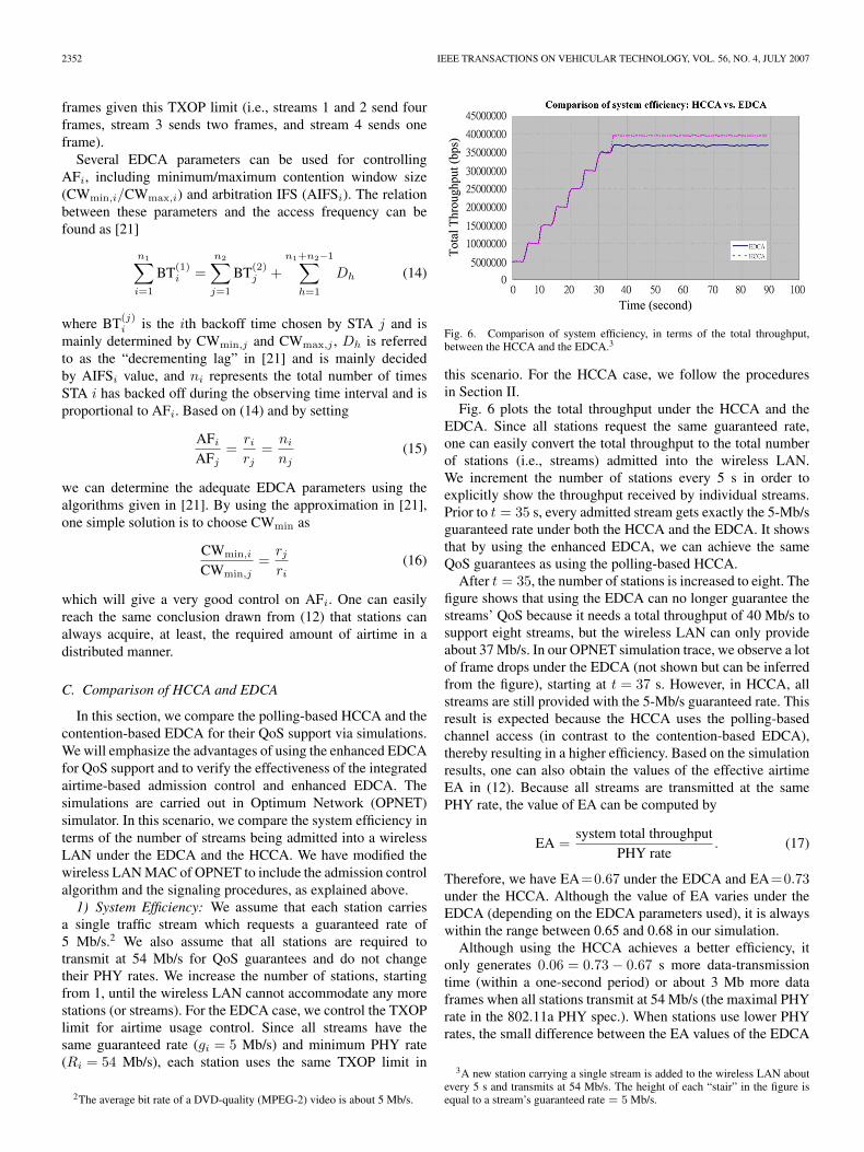
Fig. 6. Comparison of system efficiency, in terms of the total throughput,between the HCCA and the EDCA.3
this scenario. For the HCCA case, we follow the proceduresin Section II.
Fig. 6 plots the total throughput under the HCCA and theEDCA. Since all stations request the same guaranteed rate,one can easily convert the total throughput to the total numberof stations (i.e., streams) admitted into the wireless LAN.We increment the number of stations every 5 s in order toexplicitly show the throughput received by individual streams.Prior to t = 35 s, every admitted stream gets exactly the 5-Mb/sguaranteed rate under both the HCCA and the EDCA. It showsthat by using the enhanced EDCA, we can achieve the sameQoS guarantees as using the polling-based HCCA.
After t = 35, the number of stations is increased to eight. Thefigure shows that using the EDCA can no longer guarantee thestreams’ QoS because it needs a total throughput of 40 Mb/s tosupport eight streams, but the wireless LAN can only provideabout 37 Mb/s. In our OPNET simulation trace, we observe a lotof frame drops under the EDCA (not shown but can be inferredfrom the figure), starting at t = 37 s. However, in HCCA, allstreams are still provided with the 5-Mb/s guaranteed rate. Thisresult is expected because the HCCA uses the polling-basedchannel access (in contrast to the contention-based EDCA),thereby resulting in a higher efficiency. Based on the simulationresults, one can also obtain the values of the effective airtimeEA in (12). Because all streams are transmitted at the samePHY rate, the value of EA can be computed by
EA =system total throughput
PHY rate. (17)
Therefore, we have EA=0.67 under the EDCA and EA=0.73under the HCCA. Although the value of EA varies under theEDCA (depending on the EDCA parameters used), it is alwayswithin the range between 0.65 and 0.68 in our simulation.
Although using the HCCA achieves a better efficiency, itonly generates 0.06 = 0.73 − 0.67 s more data-transmissiontime (within a one-second period) or about 3 Mb more dataframes when all stations transmit at 54 Mb/s (the maximal PHYrate in the 802.11a PHY spec.). When stations use lower PHYrates, the small difference between the EA values of the EDCA
3A new station carrying a single stream is added to the wireless LAN aboutevery 5 s and transmits at 54 Mb/s. The height of each “stair” in the figure isequal to a stream’s guaranteed rate = 5 Mb/s.
SHANKAR N AND VAN DER SCHAAR: ANALYSIS OF VIDEO TRANSMISSION OVER IEEE 802.11a/e WLANs 2353
and the HCCA results in an even smaller throughput difference.Therefore, one can expect that using the EDCA and the HCCAwill generate a similar performance, particularly in terms of thetotal number of admissible streams.
The greatest advantage of using the HCCA for QoS guaran-tees is higher system efficiency (i.e., a higher EA value), whichis due to the HCCA’s contention-free nature. Due to this higherefficiency, the HCCA can provide more resource and may admitmore traffic streams than the EDCA. However, there are severalpotential problems of using the HCCA, primarily due to itscentralized access control.
1) As pointed out in the IEEE 802.11 standard, the oper-ation of the polling-based channel access may requireadditional coordination to permit efficient operation incases where multiple polling-based wireless LANs areoperating on the same channel in an overlapping physicalspace. New standard supplements such as 802.11k arebeing developed to facilitate the required coordination,but additional operations such as monitoring the channelactivity (via 802.11k) may incur control overhead, hencedegrading the system efficiency. On the other hand, theEDCA does not need any coordination between wirelessLANs using the same channel because the EDCA isdesigned to solve the channel sharing problem.
2) The HC in the HCCA needs to recompute the serviceschedule whenever a new traffic stream joins or an exist-ing stream leaves the wireless LANs. However, the ACUin the EDCA assigns the appropriate EDCA parametersset to the new stream, and the existing streams maynot need to make any adjustment,4 as explained in theprevious section.
3) The QoS of a traffic stream can only be guaranteed ifthe WSTA transmits at a (physical) rate higher than thenegotiated minimum physical rate. If a station lowers itsphysical transmission rate (below the negotiated rate),the amount of airtime originally allocated to the stream(by the HC) may not suffice to support the required QoSeven though the HC may still have enough unallocatedresource to support that stream’s QoS at this lower rate.Of course, the HC can temporarily allocate more airtime(by recomputing the service schedule) to support thatstream’s QoS at this lower rate. However, if more newstreams request for QoS later, the HC needs to cut thestream’s airtime allocation back to the originally negoti-ated amount since the HC needs airtime for new streams.However, using the EDCA will not require the AP or theACU to reallocate airtime because WSTAs can automati-cally obtain the extra amount of airtime according to (12).Consider the previous example again. Stations 1 and 2can actually halve their PHY rates and still meet the QoSrequirements. In other words, the QoS can be automat-ically provided by the EDCA, regardless of the currentphysical transmission rate the station is operating, as longas the system airtime resource allows. The new streamswill get the required amount of airtime as the airtimeallocation is adjusted automatically according to (12).
4It depends on which airtime control methods of the EDCA are applied.
Having explained the advantages of using admission controland how to implement it in EDCA, we will now show howthe quality of multimedia can be enhanced if the APP andPHY layers pass some information to the MAC layer. Althoughthese techniques can be applied to both HCCA and EDCA ofIEEE 802.11e, we concentrate the cross-layer implementationon IEEE 802.11e HCCA only because the HCCA is capable ofproviding tight QoS bounds and enhanced multimedia perfor-mance. The next section will highlight some useful knobs formultimedia that are available at the MAC layer and how theseknobs can be tuned to obtain the optimal performance.
IV. EFFICIENT MAPPING OF PRIORITIZED (SCALABLE)VIDEO ONTO 802.11e TSPEC PARAMETERS
The implementation of the simple scheduler explained inSection II is easy, but it can be quite inefficient for videostreaming applications. This is because the video traffic variesover time and consists of frames/packets with considerablyvarying sizes and different delay constraints. Normally, onewould consider the video as one stream and set the TSPECparameters so that the MAC of IEEE 802.11e HCCA woulddo the admission control and scheduling as outlined previously.This often results in a lower number of video flows/applicationsadmitted because not all layers are important for the properreception of video. We termed this method in [15] as globalTSPEC or global flow. To improve the overall system utiliza-tion, we introduce the subflow concept in which a video flow(bitstream) is divided into several subflows according to theirrelative priorities based on the overall distortion of the decodedvideo. The APP layer enables each subflow (priority layer) ofthe video to interface with the MAC as a separate flow. Thisensures that more users can be admitted into the network whileguaranteeing a minimum acceptable quality for the alreadyadmitted users. Also, by setting different delay bounds fordifferent subflows, it allows the MAC to admit more users at thesame video quality. The subflow concept can be implementedfor each video coder for which the bitstream can be prioritized.
The proposed subflow concept can be implemented usingany prioritized nonscalable (e.g., MPEG-2, H.264) or scalablevideo coding scheme. However, nonscalable video coding al-gorithms do not provide the same graceful degradation andadaptability to a large range of wireless channel conditionsand power constraints as provided by state-of-the-art scalablecoding schemes. Hence, although the concepts proposed inthis paper can potentially be deployed with state-of-the-artnonscalable coding with or without bitstream switching orlayered principles, this usually entails higher complexity andsmaller granularity for real-time adaptation across the variouslayers of the OSI stack. Consequently, in this paper, we use arecently proposed scalable 3-D wavelet video coding based onmotion compensated temporal filtering (MCTF) [22]. MCTF-based scalable video compression is attractive for wirelessstreaming applications since it provides on-the-fly adaptationto channel conditions, support for a variety of wireless receiverswith different resource capabilities and power constraints, andeasy prioritization of various coding layers and video packets.For this wavelet video coder, the subflow concept enables
2354 IEEE TRANSACTIONS ON VEHICULAR TECHNOLOGY, VOL. 56, NO. 4, JULY 2007
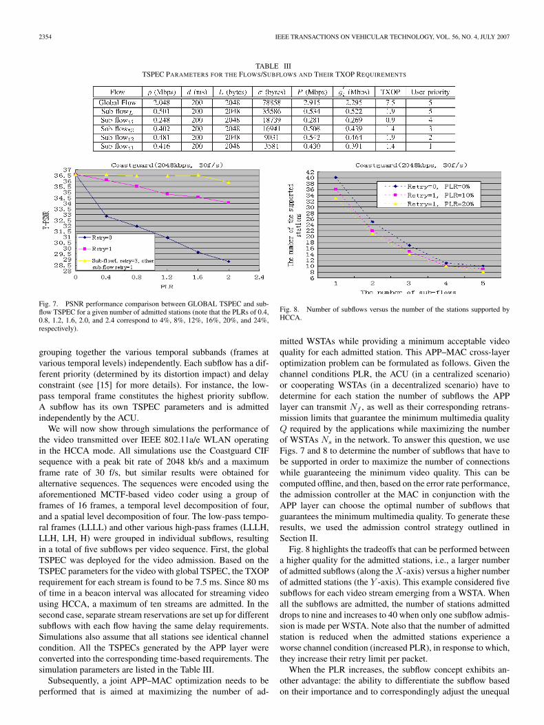
TABLE IIITSPEC PARAMETERS FOR THE FLOWS/SUBFLOWS AND THEIR TXOP REQUIREMENTS
Fig. 7. PSNR performance comparison between GLOBAL TSPEC and sub-flow TSPEC for a given number of admitted stations (note that the PLRs of 0.4,0.8, 1.2, 1.6, 2.0, and 2.4 correspond to 4%, 8%, 12%, 16%, 20%, and 24%,respectively).
grouping together the various temporal subbands (frames atvarious temporal levels) independently. Each subflow has a dif-ferent priority (determined by its distortion impact) and delayconstraint (see [15] for more details). For instance, the low-pass temporal frame constitutes the highest priority subflow.A subflow has its own TSPEC parameters and is admittedindependently by the ACU.
We will now show through simulations the performance ofthe video transmitted over IEEE 802.11a/e WLAN operatingin the HCCA mode. All simulations use the Coastguard CIFsequence with a peak bit rate of 2048 kb/s and a maximumframe rate of 30 f/s, but similar results were obtained foralternative sequences. The sequences were encoded using theaforementioned MCTF-based video coder using a group offrames of 16 frames, a temporal level decomposition of four,and a spatial level decomposition of four. The low-pass tempo-ral frames (LLLL) and other various high-pass frames (LLLH,LLH, LH, H) were grouped in individual subflows, resultingin a total of five subflows per video sequence. First, the globalTSPEC was deployed for the video admission. Based on theTSPEC parameters for the video with global TSPEC, the TXOPrequirement for each stream is found to be 7.5 ms. Since 80 msof time in a beacon interval was allocated for streaming videousing HCCA, a maximum of ten streams are admitted. In thesecond case, separate stream reservations are set up for differentsubflows with each flow having the same delay requirements.Simulations also assume that all stations see identical channelcondition. All the TSPECs generated by the APP layer wereconverted into the corresponding time-based requirements. Thesimulation parameters are listed in the Table III.
Subsequently, a joint APP–MAC optimization needs to beperformed that is aimed at maximizing the number of ad-
Fig. 8. Number of subflows versus the number of the stations supported byHCCA.
mitted WSTAs while providing a minimum acceptable videoquality for each admitted station. This APP–MAC cross-layeroptimization problem can be formulated as follows. Given thechannel conditions PLR, the ACU (in a centralized scenario)or cooperating WSTAs (in a decentralized scenario) have todetermine for each station the number of subflows the APPlayer can transmit Nf , as well as their corresponding retrans-mission limits that guarantee the minimum multimedia qualityQ required by the applications while maximizing the numberof WSTAs Ns in the network. To answer this question, we useFigs. 7 and 8 to determine the number of subflows that have tobe supported in order to maximize the number of connectionswhile guaranteeing the minimum video quality. This can becomputed offline, and then, based on the error rate performance,the admission controller at the MAC in conjunction with theAPP layer can choose the optimal number of subflows thatguarantees the minimum multimedia quality. To generate theseresults, we used the admission control strategy outlined inSection II.
Fig. 8 highlights the tradeoffs that can be performed betweena higher quality for the admitted stations, i.e., a larger numberof admitted subflows (along the X-axis) versus a higher numberof admitted stations (the Y -axis). This example considered fivesubflows for each video stream emerging from a WSTA. Whenall the subflows are admitted, the number of stations admitteddrops to nine and increases to 40 when only one subflow admis-sion is made per WSTA. Note also that the number of admittedstation is reduced when the admitted stations experience aworse channel condition (increased PLR), in response to which,they increase their retry limit per packet.
When the PLR increases, the subflow concept exhibits an-other advantage: the ability to differentiate the subflow basedon their importance and to correspondingly adjust the unequal
SHANKAR N AND VAN DER SCHAAR: ANALYSIS OF VIDEO TRANSMISSION OVER IEEE 802.11a/e WLANs 2355
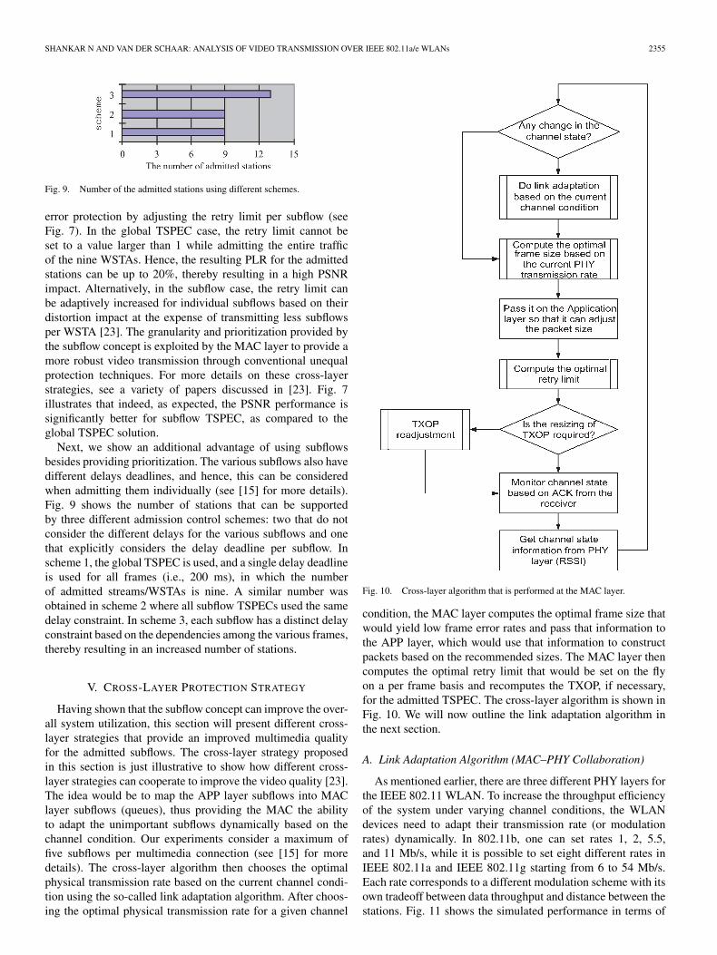
Fig. 9. Number of the admitted stations using different schemes.
error protection by adjusting the retry limit per subflow (seeFig. 7). In the global TSPEC case, the retry limit cannot beset to a value larger than 1 while admitting the entire trafficof the nine WSTAs. Hence, the resulting PLR for the admittedstations can be up to 20%, thereby resulting in a high PSNRimpact. Alternatively, in the subflow case, the retry limit canbe adaptively increased for individual subflows based on theirdistortion impact at the expense of transmitting less subflowsper WSTA [23]. The granularity and prioritization provided bythe subflow concept is exploited by the MAC layer to provide amore robust video transmission through conventional unequalprotection techniques. For more details on these cross-layerstrategies, see a variety of papers discussed in [23]. Fig. 7illustrates that indeed, as expected, the PSNR performance issignificantly better for subflow TSPEC, as compared to theglobal TSPEC solution.
Next, we show an additional advantage of using subflowsbesides providing prioritization. The various subflows also havedifferent delays deadlines, and hence, this can be consideredwhen admitting them individually (see [15] for more details).Fig. 9 shows the number of stations that can be supportedby three different admission control schemes: two that do notconsider the different delays for the various subflows and onethat explicitly considers the delay deadline per subflow. Inscheme 1, the global TSPEC is used, and a single delay deadlineis used for all frames (i.e., 200 ms), in which the numberof admitted streams/WSTAs is nine. A similar number wasobtained in scheme 2 where all subflow TSPECs used the samedelay constraint. In scheme 3, each subflow has a distinct delayconstraint based on the dependencies among the various frames,thereby resulting in an increased number of stations.
V. CROSS-LAYER PROTECTION STRATEGY
Having shown that the subflow concept can improve the over-all system utilization, this section will present different cross-layer strategies that provide an improved multimedia qualityfor the admitted subflows. The cross-layer strategy proposedin this section is just illustrative to show how different cross-layer strategies can cooperate to improve the video quality [23].The idea would be to map the APP layer subflows into MAClayer subflows (queues), thus providing the MAC the abilityto adapt the unimportant subflows dynamically based on thechannel condition. Our experiments consider a maximum offive subflows per multimedia connection (see [15] for moredetails). The cross-layer algorithm then chooses the optimalphysical transmission rate based on the current channel condi-tion using the so-called link adaptation algorithm. After choos-ing the optimal physical transmission rate for a given channel
Fig. 10. Cross-layer algorithm that is performed at the MAC layer.
condition, the MAC layer computes the optimal frame size thatwould yield low frame error rates and pass that information tothe APP layer, which would use that information to constructpackets based on the recommended sizes. The MAC layer thencomputes the optimal retry limit that would be set on the flyon a per frame basis and recomputes the TXOP, if necessary,for the admitted TSPEC. The cross-layer algorithm is shown inFig. 10. We will now outline the link adaptation algorithm inthe next section.
A. Link Adaptation Algorithm (MAC–PHY Collaboration)
As mentioned earlier, there are three different PHY layers forthe IEEE 802.11 WLAN. To increase the throughput efficiencyof the system under varying channel conditions, the WLANdevices need to adapt their transmission rate (or modulationrates) dynamically. In 802.11b, one can set rates 1, 2, 5.5,and 11 Mb/s, while it is possible to set eight different rates inIEEE 802.11a and IEEE 802.11g starting from 6 to 54 Mb/s.Each rate corresponds to a different modulation scheme with itsown tradeoff between data throughput and distance between thestations. Fig. 11 shows the simulated performance in terms of

2356 IEEE TRANSACTIONS ON VEHICULAR TECHNOLOGY, VOL. 56, NO. 4, JULY 2007
Fig. 11. Link adaptation algorithm for IEEE 802.11a.
the throughput for each modulation scheme available in IEEE802.11b versus the SNR. Note that distance is related to SNRas SNR ∼ (1/distα). Here, α is called the path attenuationfactor. The higher transmission rate represents a more complexmodulation scheme and, hence, offers a larger throughput, butit also has increased sensitivity to channel noise, thus providinga shorter operating range. Usually, one would want to extendthe operating range as much as possible and, at the same time,to maximize the throughput. This can be done by matching themodulation scheme to the SNR or the received signal strengthindicator (RSSI) available at the receiving WSTA MAC.
The cross-layer optimization problem can be formulated asfollows. Given the channel conditions RSSI (e.g., in terms ofSNR), determine the APP layer rate of the base layer Rbl
and enhancement layer rate Rel, the MAC layer packet-sizeL and the PHY modulation strategy m that maximize themultimedia quality Q, i.e., find the optimal cross-layer strategySopt(x) = arg maxS Q(S(x)) with S(x) = {Rbl, Rel, P,m}.Having explained the essential control knobs that can be tunedfor optimal performance from the MAC perspective, we nowturn our attention to the fairness in multirate wireless networksin general and show how this can influence the performanceof WLAN system. This fairness is essential as it plays animportant role in determining the quality of multimedia.
The link adaptation algorithm considered in this paper isbased on the RSSI. The MAC uses the RSSI value of thereceived frames to select an appropriate link rate. The RSSI isproportional to the received power Precd and is given by
RSSI ∝ Precd. (18)
Precd is related to the transmitted power by the followingrelation:
Precd ∝ Ptrans × dist−α. (19)
The attenuation factor assumes different values for differ-ent propagation environments. Essentially, the link adaptationalgorithm at the MAC transmitter uses the RSSI value thatit received at the (k − 1)th instant to determine the rate Rk
i .Here, the superscript denotes the kth instant, and the subscripti denotes the rate i(∈ {1, 2, . . . , 8}). In the above example,we considered IEEE 802.11a PHY that has eight differentmodulation schemes. The link adaptation algorithm uses thelatest signal strength to determine its future rate. Since thereare eight modulation schemes, we will have eight different
thresholds on which modulation scheme to choose for a givenchannel condition. Let the thresholds be denoted by Thi. Thetransmission rate is Ri if the last received RSSI value isRSSIk−1 and is represented by the following relation: Thi <RSSIk−1 ≤ Thi+1. The boundary conditions are given by thehighest and lowest transmission rates, which are chosen if theRSSIk−1 > Th7 and RSSIk−1 ≤ Th1, respectively. Now, wecan determine the probability that the transmission rate chosenis Ri at kth transmission as follows:
Pk(Ri) =P(Thi < RSSIk−1 ≤ Thi+1
)=0.5
[erf
(Thi+1 − RSSIk−1avg√
2σ
)
− erf
(Thi − RSSIk−1avg√
2σ
)]. (20)
Now, we can easily write the transmission rate at any instancek as follows:
R =8∑
i=1
Pk(Ri)Ri. (21)
With the fixed or variable thresholds, one can easily adaptthe above equation to maximize the throughput for a Gaussianchannel. It is also easy to compute the outage probability that arate chosen does not match with the channel condition resultingin frame error. The figure below shows the performance ofthe above mathematical model. Fig. 12 shows the maximumeffective throughput obtained using different PHY mode se-lections for different SNR values. From the study in [24] andin Fig. 12(a) and (b), it is easy to see that the higher ratePHY modes result in better throughput performance in the highSNR range, while the lower rate PHY modes are better for thelow SNR range. Another observation in Fig. 12 is that smallerpacket sizes result in lower effective throughputs due to thefixed amount of MAC/PHY layer overheads for each transmis-sion attempt. Consequently, the MAC can select the modulationstrategym at the PHY that maximizes the throughput. However,the modulation strategy m selected by the MAC–PHY is notalways optimal for multimedia applications. The reason for thissuboptimal performance is that the MAC-centric optimizationfocuses only on the throughput optimization and does notconsider the resulting distortion impact. Hence, the impact onmultimedia quality (distortion) needs to be explicitly consid-ered for the cross-layer optimization.
B. Frame Length Adaptation as a Function of Channel ErrorRate (MAC–PHY Collaboration)
Having selected the number of flows/subflows and optimalphysical transmission rate, we will try to determine the opti-mal frame size that enhances the MAC layer throughput (orgoodput). The MAC–PHY cross-layer optimization problem isformulated as follows. Given the channel condition, SNR, wehave to determine the optimal frame size L∗ that optimizes theMAC layer goodput Sopt(x) = arg maxS Goodput(S(x)) withS(x) = {L}.

SHANKAR N AND VAN DER SCHAAR: ANALYSIS OF VIDEO TRANSMISSION OVER IEEE 802.11a/e WLANs 2357
Fig. 12. Link adaptation algorithm for IEEE 802.11a that shows how frame length optimization is useful. (a) MSDU size: 2000 octets. (b) MSDU size:200 octets.
The throughput (and hence the Goodput) of any wirelesssystem is a function of channel error rate. For a given channelerror rate, one can easily determine the optimal frame size thatwould keep the PLR below some thresholds. This optimizationalso depends on the modulation scheme that is chosen by theMAC layer.
To derive an analytical expression, we assume that the noiseover the wireless channel is white Gaussian with spectral den-sity N0/2. Although this model is not a realistic assumption,we believe that the error performance analysis based on theGaussian channel model will also hold for more realistic andcomplicated channel models [24]. The probability of error ina frame of size L using the modulation scheme m is a func-tion of bit error probability pm
b . Assuming an independent biterror rate (BER), the expression for frame error probability isgiven by
Pme (L) = 1 − (1 − pm
b )L . (22)
Let the number of overheads that are added to the frame be rep-resented by O. These overheads are fixed for every frame, andhence, we can get a simple expression for throughput [25] as
S =L
L + Om∗R ∗ Pm
s (L). (23)
Differentiating the above expression with respect to L andequating it to zero, we have
L∗ =−Om +
√O2
m − Om
2 log(1−pmb )
2. (24)
The second differential of the (24) is negative, suggestingthat the above expression for the optimal frame length maxi-mizes the throughput of the IEEE 802.11e system for a fixedphysical modulation scheme as well as bit rate. As indicatedabove, the MAC overhead O is fixed at 432 B. This number432 arises by counting the time duration taken in transmittingthe PLCPPreamble + PLCPHeader(= 20 µs), MACHeader(=
TABLE IVOPTIMAL FRAME SIZES FOR DIFFERENT CHANNEL BERs
36 B), ACKduration (ACK frames are always transmitted usingthe lowest physical transmission rate, and their transmission du-ration is equal to 28 µs), PIFSTime(= 25 µs) and SIFSTime(=16 µs), and translating the bits/second that would have beenlost if all those times were utilized in transmitting the data ata physical transmission rate. Table IV illustrates the optimalframe sizes for different BER using 54-Mb/s PHY rate.
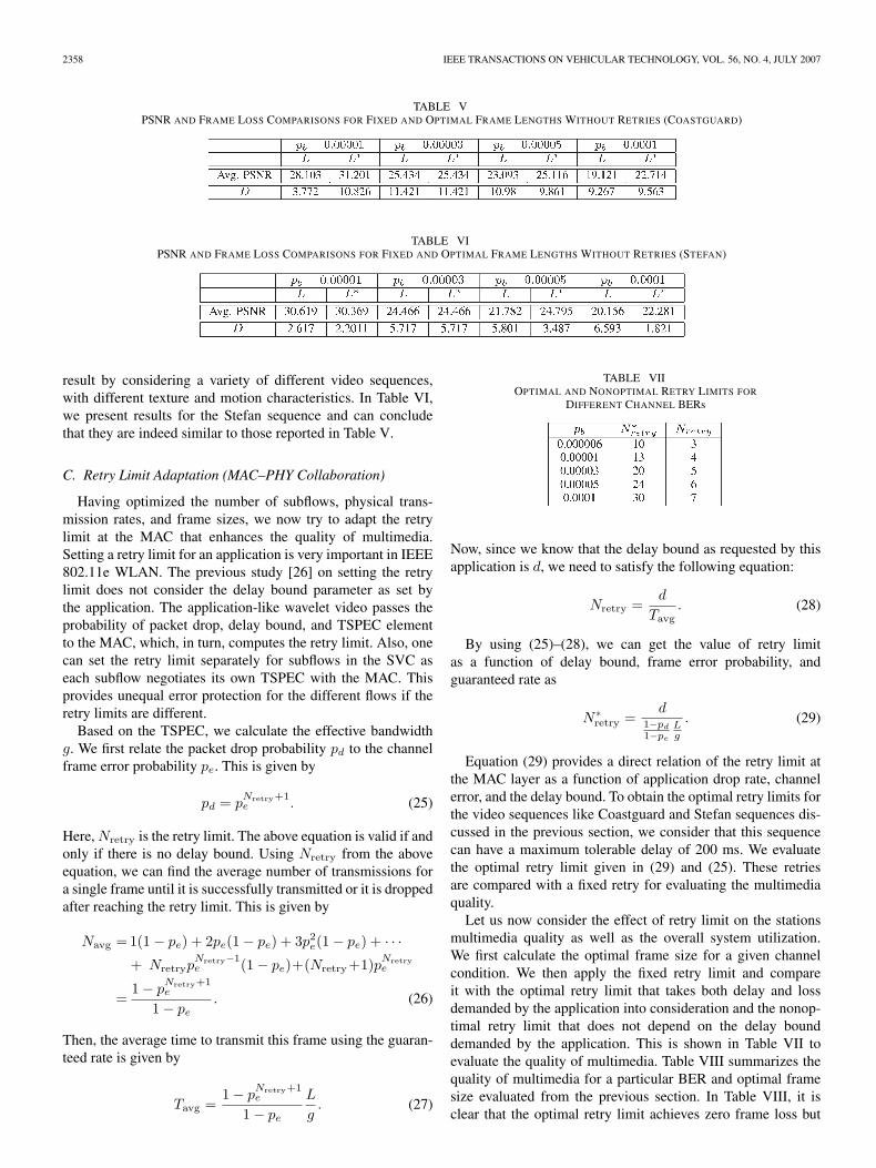
Note that the values mentioned in Table IV are obtained withthe sole purpose of maximizing the MAC throughput. Now,one needs to check if this optimal frame length determinedby the MAC is really beneficial in improving the multimediaquality at the APP layer. In order to evaluate the quality of themultimedia, we pass these optimal frame sizes to the APP layerso that it can tune its frame sizes accordingly. The resultantframe size exactly meets the expectation on the frame sizesthat optimize the throughput at the MAC layer. This scheme iscompared with a simple scheme that keeps the frame size con-stant, and the multimedia PSNR is evaluated. This is summa-rized in Table V. The video sequence considered for illustrationhere is Coastguard. The sequence was coded using a Group ofPictures of 16 frames, with four spatial and four temporal levels.The fixed frame size experiment consisted of a frame of sizeequal to 1000 B. The experiment is conducted 12 times, andthen, the PSNR mean and variations are calculated over these12 runs. The D in this experiment is the difference between themaximum and minimum PSNR values that were obtained fromthe above 12 experiments.
It is clear in Table V that the optimal frame size chosen by theMAC enhances the multimedia quality. We verified the above
2358 IEEE TRANSACTIONS ON VEHICULAR TECHNOLOGY, VOL. 56, NO. 4, JULY 2007
TABLE VPSNR AND FRAME LOSS COMPARISONS FOR FIXED AND OPTIMAL FRAME LENGTHS WITHOUT RETRIES (COASTGUARD)
TABLE VIPSNR AND FRAME LOSS COMPARISONS FOR FIXED AND OPTIMAL FRAME LENGTHS WITHOUT RETRIES (STEFAN)
result by considering a variety of different video sequences,with different texture and motion characteristics. In Table VI,we present results for the Stefan sequence and can concludethat they are indeed similar to those reported in Table V.
C. Retry Limit Adaptation (MAC–PHY Collaboration)
Having optimized the number of subflows, physical trans-mission rates, and frame sizes, we now try to adapt the retrylimit at the MAC that enhances the quality of multimedia.Setting a retry limit for an application is very important in IEEE802.11e WLAN. The previous study [26] on setting the retrylimit does not consider the delay bound parameter as set bythe application. The application-like wavelet video passes theprobability of packet drop, delay bound, and TSPEC elementto the MAC, which, in turn, computes the retry limit. Also, onecan set the retry limit separately for subflows in the SVC aseach subflow negotiates its own TSPEC with the MAC. Thisprovides unequal error protection for the different flows if theretry limits are different.
Based on the TSPEC, we calculate the effective bandwidthg. We first relate the packet drop probability pd to the channelframe error probability pe. This is given by
pd = pNretry+1e . (25)
Here, Nretry is the retry limit. The above equation is valid if andonly if there is no delay bound. Using Nretry from the aboveequation, we can find the average number of transmissions fora single frame until it is successfully transmitted or it is droppedafter reaching the retry limit. This is given by
Navg =1(1 − pe) + 2pe(1 − pe) + 3p2e(1 − pe) + · · ·+ Nretryp
Nretry−1e (1 − pe)+(Nretry+1)pNretry
e
=1 − p
Nretry+1e
1 − pe. (26)
Then, the average time to transmit this frame using the guaran-teed rate is given by
Tavg =1 − p
Nretry+1e
1 − pe
L
g. (27)
TABLE VIIOPTIMAL AND NONOPTIMAL RETRY LIMITS FOR
DIFFERENT CHANNEL BERs
Now, since we know that the delay bound as requested by thisapplication is d, we need to satisfy the following equation:
Nretry =d
Tavg. (28)
By using (25)–(28), we can get the value of retry limitas a function of delay bound, frame error probability, andguaranteed rate as
N ∗retry =
d1−pd
1−pe
Lg
. (29)
Equation (29) provides a direct relation of the retry limit atthe MAC layer as a function of application drop rate, channelerror, and the delay bound. To obtain the optimal retry limits forthe video sequences like Coastguard and Stefan sequences dis-cussed in the previous section, we consider that this sequencecan have a maximum tolerable delay of 200 ms. We evaluatethe optimal retry limit given in (29) and (25). These retriesare compared with a fixed retry for evaluating the multimediaquality.
Let us now consider the effect of retry limit on the stationsmultimedia quality as well as the overall system utilization.We first calculate the optimal frame size for a given channelcondition. We then apply the fixed retry limit and compareit with the optimal retry limit that takes both delay and lossdemanded by the application into consideration and the nonop-timal retry limit that does not depend on the delay bounddemanded by the application. This is shown in Table VII toevaluate the quality of multimedia. Table VIII summarizes thequality of multimedia for a particular BER and optimal framesize evaluated from the previous section. In Table VIII, it isclear that the optimal retry limit achieves zero frame loss but

SHANKAR N AND VAN DER SCHAAR: ANALYSIS OF VIDEO TRANSMISSION OVER IEEE 802.11a/e WLANs 2359
TABLE VIIICOMPARISON OF PSNR QUALITY OF MULTIMEDIA USING OPTIMAL FRAME LENGTH WITH DIFFERENT RETRY LIMITS
Fig. 13. PSNR performance of different video streams in the case of globalTSPEC reservation. When PLR = 10% and retry = 1, ten stations are admit-ted; when PLR = 20% and retry = 1, nine stations are admitted.
is considered an overengineered solution. On the contrary, thenonoptimal retry limit achieves good performance in terms ofPSNR and loss, and hence, it would be better to consider thenonoptimal retry limit at the MAC layer. This is a result of MAClayer trying to optimize the retry limit without consideringthe APP layer characteristics such as priorities, compressionscheme, and encoding rate.
Fig. 13 also shows the system performance using globalTSPEC but with the retry limit set to one to overcome 10% errorrate. Now, the bandwidth required by each stream increases to1.11(= 1/(1 − 0.9)) times the original bandwidth. This resultsin increased TXOP allocation per station, and hence, the num-ber of streams/WSTAs admitted is reduced by one. A similarreduction happens when the frame error rate is 20%, which isillustrated in Fig. 13.
VI. AIR TIME FAIRNESS
Having explained the different cross-layer protection strate-gies, we will look into the important concept of fairness andhow it plays an important role in determining the video qualityin a multirate environment. IEEE 802.11 standard supportsmore than one physical transmission rate. IEEE 802.11a cansupport eight different rates, namely, 54, 48, 36, 24, 18, 12,9, and 6 Mb/s while IEEE 802.11b can support four differ-ent rates, namely, 11, 5.5, 2, and 1 Mb/s. As explained in
Section V-A, depending on the channel conditions, particularlytheir distance from the QAP, WSTA may choose differenttransmission rates (i.e., “link adaptation”) in order to increasethe probability of successful transmission. For example, stationi may choose 2 Mb/s to transmit/receive data frames to/fromthe QAP while station j chooses 11 Mb/s. Defining a “fairshare of resource” among the stations in such a network is avery challenging problem, because serving an equal amountof traffic from individual stations with different transmissionrates requires allocation of different amounts of airtime. Inother words, a fair share of system throughput is no longersynonymous with a fair share of airtime in a system that sup-ports multitransmission rates. Since no such location-dependenttransmission rates exist in wired networks, applying the ex-isting scheduling algorithms without considering this propertymay result in a station’s abuse of radio resource. Multimediaapplications suffer most from airtime unfairness due to theirdelay sensitivity, which rules out rate and congestion control.For instance, assume that both WSTAs are running broadcast-quality standard-definition video streaming sessions. WSTA2has dropped its PHY rate to 1 Mb/s due to moving awayfrom the QAP. Thus, WSTA2 can no longer sustain its videostreaming application. However, the bandwidth fairness causesthe throughput of WSTA1 to drop to the same rate as WSTA2even though nothing has changed for WSTA1, leading to unfairresource usage. This observation has led us to the use of airor time fairness [12], in which each flow may use a differenttransmission rate. Let us now categorize the effects of timeunfairness analytically. Let WSTAs 1 and 2 have continu-ously backlogged traffic. Assume the frame sizes of individualstreams be fixed to size L.
The objective of fair scheduling [13] is to provide multime-dia applications with different amounts of “work” (resources)proportional to their requirements in terms of bandwidth, de-lay, and packet-loss rates. Usually, “work” is measured bythe amount of data transmitted (either in number of bytes orpackets/frames) during a certain period of time. Let Wi(t1, t2)be the amount of video flow i’s traffic served in a time interval(t1, t2), and let φi be its corresponding weight based on its re-quirements. Then, an ideal fair scheduler (i.e., the GeneralizedProcessor Scheduler [13]) for N WSTAs (and their flows) canbe defined as follows:
Wi(t1, t2)Wj(t1, t2)
≥ φi
φj, j = 1, 2, . . . , N (30)

2360 IEEE TRANSACTIONS ON VEHICULAR TECHNOLOGY, VOL. 56, NO. 4, JULY 2007
for any multimedia flow i that is continuously backloggedduring (t1, t2) [backlogged means that flow i has frames inits buffer during the specified time interval (t1, t2)]. If allmultimedia flows are transmitted at a fixed rate, we can obtain,from (30)
Wi(t1, t2)t2 − t1
≥ φi∑j φj
r (31)
where r is the physical transmission rate or the total channelcapacity. Thus, each multimedia flow i is guaranteed to have thethroughput given by (31), regardless of the states of the queuesand frame arrivals of the other flows.
We will now evaluate the total throughput degradation due toWSTAs employing link adaptation (e.g., different PHY rates)in the WLAN network. Consider n WSTAs (with all stationshaving the same frame size), with ni(
∑8i=1 ni = n) WSTAs
operating at, e.g., PHY mode i(= 1, . . . , 8), the throughputdegradation can be determined as [14]
Throughput =1
1n
(8∑
j=1
nj
Rj
) (32)
where WSTAs have different transmission rates Rj due to thedifferent PHY modes or other deployed cross-layer optimiza-tion strategies that cause this unfairness. Equation (32) can bemodified to represent the influence of frame size adopted bydifferent stations having different transmission rates. Let usassume that a station chooses a frame of size Li correspondingto the physical transmission rate Ri. The above equation thatrepresents the unfairness caused by different transmission ratesbut having the same frame size is modified to represent theunfairness caused because of different frame size as well asdifferent transmission rates as
Throughput =
8∑j=1
njLj
1n
(8∑
j=1
njLj
Rj
) . (33)
The above equation can be further generalized when eachWSTA has ki different frame sizes as
Throughput =
8∑i=1
ki∑j=1
niLij
1n
(8∑
i=1
ki∑j=1
nijLij
Rj
) . (34)
To solve this problem, we propose the concept of timefairness [14], [15]. In this concept, each WSTA is given a fairshare of time proportional to the requirements mentioned in,e.g., their TSPEC, rather than guaranteeing the bandwidth. Thistime allocation (e.g., allocated to a stream at admission time)removes the unfairness due to deploying different cross-layer
Fig. 14. PSNR performance of AFS and WFQ in different scenarios.
strategies. Equation (30) can be thus rewritten to impose timefairness as
Ti(t1, t2)Tj(t1, t2)
≥ φi
φj, j = 1, 2, . . . , N (35)
where Ti and Tj represent the time allocated to the streams iand j, respectively. We consider the transmission time allocatedto each flow, not the amount of traffic served during that inter-val, as we want to eliminate the effect of different transmissionrates (i.e., the potential unfairness it may cause). From (35),we can obtain
Ti(t1, t2) =φi∑
j
φj(t2 − t1). (36)
Equation (36) states that a flow, which is continuously back-logged in the arbitrary time period (t1, t2), is guaranteed toreceive a certain portion of transmission time given by theabove equation rather than the bandwidth guaranteed by (31).
The bandwidth fairness concept is translated into a practicalalgorithm called weighted fair queuing (WFQ), and the timefairness is translated to an implementable algorithm called airfair scheduling (AFS). The advantages of the proposed AFS[15], as opposed to the conventional WFQ, are highlighted inFig. 14. The air or time fairness concept can be employed forevery video coder. In this paper, we show the benefits of air/timefairness using a wavelet video coder. In the first simulationscenario, the same cross-layer strategies, resulting in the sametransmission rate and no losses, are deployed for both WSTAs,and the performance is compared using WFQ and AFS. WFQand AFS result in the same PSNR values as shown by the firstfour bars in the left-hand side of Fig. 14. Consider the secondsimulation scenario: WSTA1 experiences more frame errorsbecause of interference and fading. The PLR has increased,and it takes on average 50% more time to transmit a framefrom WSTA1 than from WSTA2. In the conventional WFQ,this would mean that the “start-of-service time” of frames inWSTA2 is deferred resulting in QoS violation and droppingof packets at the MAC layer. This directly affects the PSNRperformance as most of the higher priority packets are droppedfor both the WSTAs. Using AFS, the stream between theWSTA1 and AP alone is affected, yielding low PSNR, whereasthe other WSTA2 is not affected because of WSTA1’s channelerror condition. In the third simulation scenario, the WSTA1moved far away from the AP, and the cross-layer strategy

SHANKAR N AND VAN DER SCHAAR: ANALYSIS OF VIDEO TRANSMISSION OVER IEEE 802.11a/e WLANs 2361
switched the PHY mode to a more robust modulation scheme.Since the physical transmission rate of WSTA1 has dropped,it would take more time to transmit the frame, and the sameproblem of deferred start-of-service happens for both WSTAsin case of WFQ. However, the AFS isolates the channel anddifferential transmission rates to WSTA1, thus guaranteeing themultimedia performance.
The throughput degradation can be clearly measured whendifferent WSTAs in WLAN deploy different PHY modes bysimply subtracting (32) from (31). This unfairness is caused bystations having lower data rates compared to stations havinghigher data rates. However, if we measure the throughput asthe time goes to infinity, the throughput carried by multirateWLAN and unirate WLAN is the same. Thus, the performanceof the WLAN network is impacted if there are WSTAs thatoperate in multirate. In order to solve this problem, the conceptof time fairness is introduced. In this concept, each WSTAis given a fair share of time proportional to the requirementsmentioned in TSPEC rather than guaranteeing the bandwidth asthe means proportional to its weight share. This time allocationremoves the unfairness caused to in the WLAN system becauseof differential PHY rates. This is the allocated TXOP to astream at admission time.
VII. CONCLUSION
In this paper, we addressed the important problem of delay-sensitive transmission of video over IEEE 802.11a/e WLANs.We outline the admission control scheme that uses a newparameter called “channel burstiness” to model the first-ordercharacteristics of the time-varying wireless channel and thenuse effective bandwidth calculations to admit the optimalnumber of video streams. We showed how different accessmechanisms in IEEE 802.11e can provide the necessary QoSfor the admitted video applications. Additionally, we highlightthe differences between the two modes, EDCA and HCCA,in the IEEE 802.11e WLAN system and show the relativemerits and demerits. We also introduced the concept of subflowconcept that enhances the quality of video at the receiver inthe presence of errors. Then, we illustrate a simple cross-layer strategy using subflows at the APP, frame length, retrylimit at the MAC, and modulation schemes at the PHY toimprove the quality of multimedia. We showed through analysisand simulation that controlling the contention-based access inIEEE 802.11e is simpler to realize in real products and howdifferent cross-layer strategies used in polled access lead to alarger number of stations being simultaneously admitted and/ora higher video quality for the admitted stations. Finally, weintroduce the concept of air/time fairness that enables a fairdivision of resources among competing WSTAs when differentcross-layer strategies are deployed.
REFERENCES
[1] IEEE 802.11b: Wireless LAN Medium Access Control (MAC) andPhysical Layer (PHY) Specifications, IEEE Standard, 1999.
[2] Draft Supplement to Part 11: Wireless Medium Access Control (MAC)and physical layer (PHY) specifications: Medium Access Control (MAC)Enhancements for Quality of Service (QoS), IEEE 802.11e/D10.0,Nov. 2004.
[3] D. Majumdar, G. Sachs, I. V. Kozintsev, and K. Ramchandran, “Multi-cast and unicast real-time video streaming over wireless LANs,” IEEETrans. Circuits Syst. Video Technol., vol. 12, no. 6, pp. 524–534,Jun. 2002.
[4] Y. Pei and J. Modestino, “Multi-layered video transmission over wirelesschannels using an adaptive modulation and coding scheme,” in Proc.IEEE ICIP, Thessaloniki, Greece, Oct. 2001, pp. 1009–1012.
[5] Y. Shan and A. Zakhor, “Cross layer techniques for adaptive videostreaming over wireless networks,” in Proc. IEEE ICME, 2002, vol. 1,pp. 277–280.
[6] W. Kumwilaisak, T. Hou, Q. Zhang, W. Zhu, C.-C. Jay Kuo, andY.-Q. Zhang, “A cross-layer quality of service mapping architecture forvideo delivery in wireless networks,” IEEE J. Sel. Areas Commun.,vol. 21, no. 10, pp. 1685–1698, Dec. 2003.
[7] J. Shin, J. G. Kim, J. Kim, and C.-C. J. Kuo, “Dynamic QoS map-ping control for streaming video in relative service differentiationnetworks,” Eur. Trans. Telecommun., vol. 12, no. 3, pp. 217–230,May/Jun. 2001.
[8] B. Girod, M. Kalman, Y. Liang, and R. Zhang, “Advances in channel-adaptive video streaming,” Wirel. Commun. Mob. Comput., vol. 2, no. 6,pp. 549–552, Sep. 2002 (Invited Paper).
[9] A. Reibman and M.-T. Sun, Eds., Compressed Video Over Networks.New York: Marcel Dekker, 2000.
[10] S. Shakkottai, T. S. Rappaport, and P. C. Karlsson, “Cross-layer designfor wireless networks,” IEEE Commun. Mag., vol. 41, no. 10, pp. 74–80,Oct. 2003.
[11] P. Ansel, Q. Ni, and T. Turletti, “An efficient scheduling scheme forIEEE 802.11e,” in Proc. IEEE Model. Optimization Mobile, Ad HocWireless Netw. Workshop (WiOpt). Cambridge, U.K.: Univ. Cambridge,Mar. 24–26, 2004.
[12] S. Shankar N, “Method, access point and program product for providingbandwidth and airtime fairness in wireless networks,” World Patent No.WO2005011199, May 3, 2006.
[13] A. K. Parekh and R. G. Gallager, “A generalized process sharing approachto flow control in integrated services networks—The single node case,” inProc. IEEE INFOCOM, 1992, pp. 915–924.
[14] S. Shankar N, R. Chen, R. Schmitt, C. T. Chou, and K. G.Shin, “Air fairscheduling for multimedia transmission over multi rate wireless LANs,”in Proc. SOIA, Eindhoven, The Netherlands, 2004.
[15] S. Shankar N, Z. Hu, and M. van der Schaar, “Cross-layer optimizedtransmission of wavelet video over IEEE 802.11a/e WLANs,” in Proc.IEEE Packet Video, Irvine, CA, Dec. 2004.
[16] M. van der Schaar and S. Shankar N, Cross-layer Design for WirelessMultimedia Transmission, Jun. 2005. accepted book chapter.
[17] M. Zorzi, R. R. Rao, and L. B. Milstein, “On the accuracy of a first-orderMarkov model for data transmission on fading channels,” in Proc. IEEEICUPC, Nov. 1995, pp. 211–215.
[18] D. Wu and R. Negi, “Effective capacity-based quality of service measuresfor wireless networks,” ACM Mob. Netw. Appl., vol. 11, no. 1, pp. 91–99,Feb. 2006.
[19] C. Liu and J. Leyland, “Scheduling algorithms for multiprogramming inhard real-time environment,” J. ACM, vol. 20, no. 1, pp. 46–61, Jan. 1973.
[20] C. T. Chou, S. Shankar N, and K. G. Shin, “Per-stream QoS in the IEEE802.11e Wireless LAN: An integrated airtime-based admission controland distributed airtime allocation,” in Proc. IEEE INFOCOM, Miami, FL,Mar. 2005, pp. 1584–1595.
[21] C. T. Chou, S. Shankar N, and K. G. Shin, “Contention-based airtimeusage control in multirate IEEE 802.11 wireless LANs,” in IEEE/ACMTrans. Netw., vol. 14, Dec. 2006, pp. 1179–1192.
[22] J.-R. Ohm, M. van der Schaar, and J. W. Woods, “Interframe waveletcoding—Motion picture representation for universal scalability,” SignalProcess. Image Commun., vol. 19, no. 9, pp. 877–908, Oct. 2004.
[23] M. van der Schaar and S. Shankar N, “Cross-layer wireless multimediatransmission: Challenges, principles and new paradigms,” IEEE WirelessCommun. Mag., vol. 12, no. 4, pp. 50–58, Aug. 2005.
[24] D. Qiao, S. Choi, and K. G. Shin, “Goodput analysis and link adaptationfor IEEE 802.11a wireless LAN,” IEEE Trans. Mobile Comput., vol. 1,no. 4, pp. 278–292, Oct.–Dec. 2002.
[25] M. Schwartz, Telecommunication Networks: Protocols, Modeling, andAnalysis. Reading, MA: Addison-Wesley, 2005.
[26] Q. Li and M. van der Schaar, “Providing adaptive QoS to layered videoover wireless local area networks through real-time retry limit adapta-tion,” IEEE Trans. Multimedia, vol. 6, no. 2, pp. 278–290, Mar. 2004.
[27] A. Grilo, M. Macedo, and M. Nunes, “Scheduling algorithm for QoS sup-port in IEEE 802.11e networks,” IEEE Wireless Commun. Mag., vol. 10,no. 3, pp. 36–43, Jun. 2003.

2362 IEEE TRANSACTIONS ON VEHICULAR TECHNOLOGY, VOL. 56, NO. 4, JULY 2007
Sai Shankar N (M’99–SM’04) received the Ph.D. degree from the Depart-ment of Electrical Communication Engineering, Indian Institute of Science,Bangalore, in the area of ATM networks.
In 1999, he joined Philips Research, Eindhoven, The Netherlands, wherehe served as a Research Scientist, working on various problems involv-ing hybrids, fiber, coaxial cable (IEEE 802.14) networks, and IP proto-cols. In 2001, he joined Philips Research, Briarcliff Manor, NY, where heworked in the area of wireless LANs/UWB, cognitive radios, and cooper-ative communications. He was an active contributor of the wireless LANstandard and has submitted more than 15 proposals that have shaped QoSrelated issues in the IEEE 802.11e Standard. He is also an active participantin the Ultra-Wideband (UWB) Working Group of the WiMEdia Allianceand has contributed to shaping the new MAC at the Multiband OFDMAlliance (MBOA) Forum. He has been the reviewer for almost all impor-tant journals in the area of networking and has chaired many conferences.Currently, he is with Qualcomm, Inc., San Diego, CA, researching UWB,cognitive radios, and cooperative communications. He has authored morethan 45 conference and journal papers and is the holder of more than40 patents.
Dr. Shankar N was awarded the German Fellowship, DAAD, from theDepartment of Mathematics, University of Kaiserslautern, Kaiserslautern,Germany, to work on queueing approaches in manufacturing in 1998. He wasnominated as one of the five finalists for the Innovator of the Year category byEETimes.
Mihaela van der Schaar (SM’04) received the Ph.D. degree from EindhovenUniversity of Technology, Eindhoven, The Netherlands, in 2001.
Prior to joining the faculty of the Electrical Engineering Department, Univer-sity of California at Los Angeles, on July 1, 2005, she was a Senior Researcherwith Philips Research in the Netherlands and in the U.S. between 1996 andJune 2003, where she led a team of researchers working on multimediacoding, processing, networking, and streaming algorithms and architectures.From July 1, 2003 to July 1, 2005, she was an Assistant Professor with theElectrical and Computer Engineering Department, University of California,Davis. She has published extensively on multimedia compression, processing,communications, networking, and architectures. She is the holder of 27 grantedU.S. patents and has several more pending.
Dr. van der Schaar was elected as a member of the Technical Committee onMultimedia Signal Processing of the IEEE Signal Processing Society. Since1999, she has been an active participant in the ISO Motion Picture ExpertGroup (MPEG) standard to which she made more than 50 contributions andreceived three ISO recognition awards. She chaired for three years, the ad hocgroup on MPEG-21 Scalable Video Coding, and also cochaired the MPEGad hoc group on Multimedia Test-bed. She was an Associate Editor of theIEEE TRANSACTIONS ON MULTIMEDIA and the SPIE Electronic ImagingJournal from 2002 to 2005. Currently, she is an Associate Editor of the IEEETRANSACTIONS ON CIRCUITS AND SYSTEMS FOR VIDEO TECHNOLOGY
and an Associate Editor of the IEEE SIGNAL PROCESSING LETTERS. Shereceived the NSF CAREER Award in 2004, the IBM Faculty Award in 2005,and the Best Paper Award for her paper published in 2005 in the IEEETRANSACTIONS ON CIRCUITS AND SYSTEMS FOR VIDEO TECHNOLOGY.