performance assessment of an advanced hydronic...
TRANSCRIPT

Performance Assessment of an Advanced Hydronic Heat Pump
1017887


Performance Assessment of an Advanced Hydronic Heat Pump
1017887
Technical Update, December 2009
EPRI Project Manager
K.R. Amarnath
ELECTRIC POWER RESEARCH INSTITUTE 3420 Hillview Avenue, Palo Alto, California 94304-1338 ▪ PO Box 10412, Palo Alto, California 94303-0813 ▪ USA
800.313.3774 ▪ 650.855.2121 ▪ [email protected] ▪ www.epri.com

DISCLAIMER OF WARRANTIES AND LIMITATION OF LIABILITIES
THIS DOCUMENT WAS PREPARED BY THE ORGANIZATION(S) NAMED BELOW AS AN ACCOUNT OF WORK SPONSORED OR COSPONSORED BY THE ELECTRIC POWER RESEARCH INSTITUTE, INC. (EPRI). NEITHER EPRI, ANY MEMBER OF EPRI, ANY COSPONSOR, THE ORGANIZATION(S) BELOW, NOR ANY PERSON ACTING ON BEHALF OF ANY OF THEM:
(A) MAKES ANY WARRANTY OR REPRESENTATION WHATSOEVER, EXPRESS OR IMPLIED, (I) WITH RESPECT TO THE USE OF ANY INFORMATION, APPARATUS, METHOD, PROCESS, OR SIMILAR ITEM DISCLOSED IN THIS DOCUMENT, INCLUDING MERCHANTABILITY AND FITNESS FOR A PARTICULAR PURPOSE, OR (II) THAT SUCH USE DOES NOT INFRINGE ON OR INTERFERE WITH PRIVATELY OWNED RIGHTS, INCLUDING ANY PARTY'S INTELLECTUAL PROPERTY, OR (III) THAT THIS DOCUMENT IS SUITABLE TO ANY PARTICULAR USER'S CIRCUMSTANCE; OR
(B) ASSUMES RESPONSIBILITY FOR ANY DAMAGES OR OTHER LIABILITY WHATSOEVER (INCLUDING ANY CONSEQUENTIAL DAMAGES, EVEN IF EPRI OR ANY EPRI REPRESENTATIVE HAS BEEN ADVISED OF THE POSSIBILITY OF SUCH DAMAGES) RESULTING FROM YOUR SELECTION OR USE OF THIS DOCUMENT OR ANY INFORMATION, APPARATUS, METHOD, PROCESS, OR SIMILAR ITEM DISCLOSED IN THIS DOCUMENT.
ORGANIZATION(S) THAT PREPARED THIS DOCUMENT
Electric Power Research Institute (EPRI)
This is an EPRI Technical Update report. A Technical Update report is intended as an informal report of continuing research, a meeting, or a topical study. It is not a final EPRI technical report.
NOTE
For further information about EPRI, call the EPRI Customer Assistance Center at 800.313.3774 or e-mail [email protected].
Electric Power Research Institute, EPRI, and TOGETHER…SHAPING THE FUTURE OF ELECTRICITY are registered service marks of the Electric Power Research Institute, Inc.
Copyright © 2009 Electric Power Research Institute, Inc. All rights reserved.

CITATIONS This document was prepared by
Electric Power Research Institute (EPRI) 942 Corridor Park Blvd. Knoxville, TN 37932
Principal Investigators R. Domitrovic C. Trueblood
This document describes research sponsored by the Electric Power Research Institute (EPRI).
This publication is a corporate document that should be cited in the literature in the following manner:
Performance Assessment of an Advanced Hydronic Heat Pump. EPRI, Palo Alto, CA: 2009. 1017887.
iii


PRODUCT DESCRIPTION This report details testing of the Daikin Altherma, a variable speed hydronic heat pump for residential and small commercial application. The system is a highly flexible provider of relatively high-grade (high temperature) heat or cooling for a residence or small commercial institution. Nominal capacity is 36,000 Btu/hr, but this capacity can be exceeded depending on conditions. It is an air-to-water heat pump operating on the standard reverse-Rankine cycle with R-410a as the refrigerant. The outdoor heat exchanger is air-to-refrigerant and the indoor heat exchanger is refrigerant-to-water. The indoor heat exchanger is housed in a module called the “hydro-box” that contains a water circulating pump, auxiliary heater, and controls. Output from the hydro-box is water, cooled or heated by the heat pump, that can be piped to serve a variety of externally connected heat exchange devices for space heating/cooling and domestic water heating. The tested configuration had a Daikin domestic water heater connected, with an integral water heat exchanger made specifically for use with the Altherma system. Additionally, a Trane fan coil water-to-air air handler was tied to the Altherma water loop to provide space heating and cooling. The water loop had an integrated 3-way valve isolating the domestic tank from the fan-coil circuit. The water circuit can also be used for radiant floor heating applications by piping hot water through floor embedded tubing, but this heating technique was not tested in the current setup. All major components of the Altherma are variable speed, including an inverter driven scroll compressor and outdoor unit fans. All components are actively monitored and controlled by the Altherma controller according to the operating mode. The main controller allows for a variety of operating modes and allows priorities to be set according to a day and time calendar for domestic hot water production. Both the hydro-box water circuit and the domestic water tank have integrated backup heaters that are triggered by the main controller under certain conditions such as a heat pump fault or high demand conditions.
Results and Findings The report summarizes testing of the Daikin Altherma operating in heating and cooling modes and in water heating mode, with an emphasis on assessing the flexibility of system operation, its applicability for use in new construction and retrofit residential and small commercial applications, and its potential for energy savings and demand reduction.
Challenges and Objectives The technology of air conditioning for residences and small commercial buildings has lagged that of larger buildings and campuses, mainly because of the relatively low historical cost of energy and the desire for low initial cost of equipment. As a result, the state of the art for residential and small commercial cooling is somewhat non-sophisticated and relatively energy inefficient. Because air conditioning is a two-variable problem—sensible cooling and latent heat removal—there is no one-size-fits-all air conditioning system for all climates and comfort needs. A proper understanding of the conditioning requirements and of the equipment available to reach those requirements is needed to design and implement systems that provide optimum value.
Applications, Values, and Use Near-term developments for residential and small commercial air conditioning will focus on proper application of equipment and on development of the underlying technology. Proper application of equipment requires that engineers, designers, sellers, and installers of air
v

conditioning systems understand the options available. How systems operate and provide benefit depends on climate, building load, and indoor requirements.
EPRI Perspective Utilities have a vested interest in promoting the efficient use of electricity. Heating and air conditioning of building space employs multiple fuels and energy delivery means to achieve comfort; and advances in technology can cause shifts in the optimum choice of equipment, methods, and energy sources for space conditioning. One historical criticism of heat pumps for residential heating applications has been the relatively cool air produced at the register. Standard efficiency single-speed heat pumps provide supply air in the 100°F range depending on surrounding conditions; this is 20°F or more lower than a gas furnace. Development of heat pumps that can efficiently and reliably produce supply air temperatures nearing those of gas-fired counterparts while maintaining high heat pump efficiencies has long been a goal of manufacturers. The introduction of variable speed components and more sophisticated feedback controls on residential heat pumps has led to products that meet such performance requirements while maintaining the inherent efficiency advantages of the heat pump cycle.
Approach The project team installed, tested, and documented results for the Daikin Altherma product to characterize its applicability for use in typical U.S. homes and small commercial buildings. It was installed in EPRI’s Knoxville, Tennessee laboratory in a semi-controlled environment and subjected to prescribed testing methods. The team installed instrumentation to measure the cooling and heating capacity provided by the unit, power consumption, and relevant indoor and outdoor air conditions. They collected data on operation in various modes of space heating, space cooling, and domestic water heating.
Keywords Heating, Ventilating & Air Conditioning (HVAC) Water heating Heat pump Variable speed compressor Hydronic Residential Small commercial Energy efficiency
vi

ACKNOWLEDGMENTS EPRI thanks Daikin Industries, LTD. of Osaka, Japan, for supplying the Altherma and to Tao Jia of Daikin for technical product support.
vii


CONTENTS
1 EXECUTIVE SUMMARY ........................................................................................................1-1
2 INTRODUCTION ....................................................................................................................2-1 Heat Pump Cycles .........................................................................................................2-1
Altherma Description............................................................................................................2-5 Outdoor Unit ...................................................................................................................2-5 Indoor Unit......................................................................................................................2-6 Packaged Indoor & Outdoor Unit ...................................................................................2-9 Domestic Water Tank.....................................................................................................2-9 Applications..................................................................................................................2-10
3 TEST DESIGN AND PROCEDURE .......................................................................................3-1 Installation............................................................................................................................3-1 Water Supply System...........................................................................................................3-2 Instrumentation ....................................................................................................................3-3
4 RESULTS ...............................................................................................................................4-1 Heating Mode Test...............................................................................................................4-1 Cooling Mode Test ...............................................................................................................4-4 Altherma Water Heating.......................................................................................................4-8
5 IMPLICATIONS/CONCLUSIONS...........................................................................................5-1
6 RECOMMENDATIONS FOR FUTURE RESEARCH AND ACTIVITIES................................6-1
ix


LIST OF FIGURES Figure 2-1 Capacity Curves and Balance Points for Single Speed Air Conditioning .................2-3 Figure 2-2 Cooling Capacity and Space Load with a Variable Speed Air Conditioner...............2-3 Figure 2-3 Daikin Altherma ERY Series Outdoor Unit (Small Size) ...........................................2-6 Figure 2-4 Daikin, Altherma ERH Series Outdoor Unit (Large Size) .........................................2-6 Figure 2-5 Altherma Hydro-Box (Indoor Unit) ............................................................................2-7 Figure 2-6 Altherma Hydro-Box (Cover Removed)....................................................................2-8 Figure 2-7 Altherma Domestic Water Storage Tank ..................................................................2-9 Figure 3-1 Instrumentation Schematic of EPRI’s Altherma Testing Setup.................................3-1 Figure 3-2 Nominal 2-Ton Air Indoor Fan Coil ...........................................................................3-2 Figure 3-3 Domestic Water Supply Systm .................................................................................3-3 Figure 3-4 Pulse Output Water Flow Meter ...............................................................................3-4 Figure 3-5 Power Transducers ..................................................................................................3-4 Figure 4-1 Altherma Heating Profile...........................................................................................4-1 Figure 4-2 Altherma Steady-State Supply Air Temperature as a Function of Water Loop Temperature ..........................................................................................................................4-3 Figure 4-3 Altherma Steady-State Power Consumption as a Function of Water Loop Temperature ..........................................................................................................................4-4 Figure 4-4 Altherma Steady-State Heating Capacity and COP as a Function of Water Loop Temperature ..........................................................................................................................4-4 Figure 4-5 Altherma Cooling Profile...........................................................................................4-5 Figure 4-6 Altherma Cooling Profile...........................................................................................4-6 Figure 4-7 Steady-State Cooling................................................................................................4-7 Figure 4-8 Altherma Steady-State Cooling ................................................................................4-8 Figure 4-9 Altherma Cooling ......................................................................................................4-8 Figure 4-10 Draw Tests Overall COPs for Varying Outdoor Temperatures.............................4-10 Figure 4-11 Draw Test 1 - Power and Water Draw Profile.......................................................4-10
xi

1 EXECUTIVE SUMMARY The Daikin Altherma is a variable speed hydronic heat pump for residential and small commercial applications. It is an air-to-water heat pump employing the standard reverse-Rankine cycle with R-410a as the refrigerant. The outdoor heat exchanger is air-to-refrigerant and the indoor heat exchanger is refrigerant-to-water. The indoor heat exchanger is housed in a module called the “hydro-box,” which contains a water circulating pump, auxiliary heater, and controls. Output from the hydro-box is water, cooled or heated by the heat pump, that can be piped to serve a variety of externally connected heat exchange devices for space heating/cooling and domestic water heating.
The tested configuration had a Daikin domestic water heater connected, with an integral water heat exchanger made specifically for use with the Altherma system. Additionally, a Trane fan coil water-to-air, air handler was tied to the Altherma water loop to provide space heating & cooling. The air handler is nominally rated at two-tons (heating capacity) which is below the nominal rating of Altherma (3-tons) making the overall system deviate slightly from optimal performance at high capacity conditions. In an actual installation, the Altherma water loop would likely be coupled to multiple air handlers, summing to 3-tons or greater in nominal capacity. Because of Altherma’s flexibility (variable speed), it adjusts well to operation at fractional capacity operating conditions. The water loop has an integrated 3-way valve isolating the domestic tank from the fan-coil circuit. The water circuit can also be used for radiant floor heating applications by piping hot water through floor embedded tubing. This heating technique was not tested in the current setup. All major components of the Altherma are variable speed, including an inverter driven scroll compressor, and outdoor unit fans. All components are actively monitored and controlled by the Altherma controller according to the operating mode. The main controller allows for a variety of operating modes and allows priorities to be set according to a day & time calendar for domestic hot water production. Both the hydro-box water circuit and the domestic water tank have integrated backup heaters which are triggered by the main controller under certain conditions such as a heat pump fault or high demand conditions.
The Altherma is a highly flexible provider of relatively high grade (high temperature) heat or cooling for a residence or small commercial institution. Nominal capacity is 36,000 Btu/hr, but depending on conditions this can be exceeded. The Daikin Altherma is intended for both new construction and retrofit applications on residences and small commercial buildings requiring up to a nominal 5 tons of heating/cooling capacity for a single system. Multiple systems could be used in larger structures much the same way standard split-systems are deployed in numbers in medium-sized office buildings.
All major components of the Altherma are variable speed, including an inverter driven scroll compressor, and outdoor unit fans. All components are actively monitored and controlled by the Altherma controller according to the operating mode. The main controller allows for a variety of operating modes and allows priorities to be set according to a day and time calendar for domestic hot water production. Both the hydro-box water circuit and the domestic water tank have integrated backup heaters that are triggered by the main controller under certain conditions, such as a heat pump fault or high demand conditions.
1-1

Testing revealed a highly flexible system built on variable speed components: compressor, fans and expansion device that allow a user to choose a variety of performance levels. In heating mode the flexibility of the water loop temperature allows the Altherma to produce similar radiator temperatures as would be found in gas or oil fired systems and fan coil temperatures above 120°F, similar to what a gas furnace supplies.. The “cold blow” effect that has long been associated with heat pumps can be eliminated across a large range of ambient conditions because of the built-in variability of available heating capacity and the flexibility of water loop set point.
In the cooling mode, flexible water loop temperature allows the sensible heat ratio (SHR) to be adjusted accordingly as the need for humidity removal requires. This is not possible with single speed direct expansion (DX) equipment. Water loop temperature can be adjusted higher—above 50°F—to maximize efficiency or lower—in the lower 40°F range—to maximize humidity removal. These types of adjustments are not possible with conventional unitary equipment.
Altherma represents the next generation of heat pumps for residential and small commercial application, a system built around the classic unitary or split-system concept, but using variable speed components and aspects of variable control previously reserved for more sophisticated commercial systems. This type of system advances the art of small building energy management by allowing one flexible machine to provide for the continuously variable demand for heating, cooling, water heating and perhaps other energy loads, relatively simply and efficiently.
1-2

2 INTRODUCTION This report details tests of the Daikin Altherma, a variable speed hydronic heat pump for residential and small commercial building applications. The Daikin Altherma is an air-to-water heat pump operating on the standard reverse-Rankine cycle with R-410a as the refrigerant.
The tests of the Daikin Altherma were conducted for the 2009 EPRI Energy Efficiency Technologies Project Set (PS170C), part of the Energy Efficiency and Demand Response Program (170).
The approach to energy management in buildings is moving toward a method of energy budgeting, whereby the energy used by or produced by a building are shared in as efficient a manner as possible. This can be accomplished by integrating appliances that deliver energy to different applications within a building. The use of a hydronic loop to distribute heating and cooling in U.S. residences is a relatively new application. Water has long served as a means for delivering heat through radiators & fan coils, but the heat source is a direct fired boiler. The Altherma is a unique piece of equipment that uses a heat pump as an energy source, allowing one machine to supply both heating and cooling requirements. Heat pumps, and in particular, those with variable speed components, offer exceptional efficiency in terms of energy used versus energy delivered to a space.
There are many limitations and losses in heat pump systems and only a fraction of theoretical COP is ever realized. However, performance is still sufficient to make heat pumps competitive as a source of heating when compared to direct fuel combustion. For cooling applications, there is no direct fuel analog and there are fewer competitive technologies, making it the de-facto option for space cooling in temperate and tropical climates.
The introduction of variable speed compressors has enabled heat pumps that potentially offer better performance and could expand their application compared to typical air conditioning systems. Variable speed drive heat pumps may offer benefits that include:
• A greater capacity range.
• Reduced cycling losses.
• Better humidity control
• Better overall efficiency. The following section provides an explanation of why variable speed heat pumps offer potential improvements in efficiency and comfort.
Heat Pump Cycles
The heat pump cycle, technically known as the reverse-Rankine cycle, in effect uses a small amount of mechanical compression energy to transfer a larger amount of heat from a cold source reservoir to a hot sink reservoir. (In this report, “heat pump” refers to both heating and cooling applications, whereas in contemporary usage “heat pump” typically refers only to use for heating
2-1

applications.) In all heat pump applications, there are at least two heat exchangers, one rejecting heat (the condenser) and one absorbing heat (the evaporator). Either or both of these heat exchange processes can be used for useful purposes. In space conditioning applications (“air conditioning”), one heat exchange process is used to provide heat or cool to a space, while the other is lost to the outside ambient air. In certain applications, like incorporation of a de-superheater for domestic water heating, some or all of the second heat exchanger is put to gainful use.
Heat pump efficiency is intimately tied to the temperatures of the surrounding (reservoir) from which heat is either absorbed or rejected. Theoretical efficiency is tied to the absolute temperatures of the surroundings and to the temperature difference between them. Theoretical, Carnot, coefficient of performance (COP) for heating efficiency of a heat pump is given by the equation:
coldhot
hotideal TT
TCOP
−= Eq. 2-1
And cooling COP by:
coldhot
coldideal TT
TCOP
−= Eq. 2-2
Heat pump performance, measured both by capacity and efficiency, is inextricably tied to the reservoir temperatures and in turn to the temperatures of the boiling and condensing refrigerant in the heat exchangers. Because of this link, performance degrades in the direction of increasing source-sink differential, with all other variables held constant. As it becomes hotter outside an air conditioner is less able to provide cooling capacity and does so at progressively lower efficiencies. Likewise, as it gets colder outside, a heat pump is less able to provide heat and does so with progressively lower efficiency. Solutions to this dilemma have traditionally been to design a system large enough (i.e. with sufficient heating or cooling capacity) to handle the worst case scenario, or at least very close to it. Therefore, air conditioning is generally sized around the anticipated cooling load defined by an extreme design temperature which becomes the balance point, above which insufficient cooling is provided to maintain a set indoor temperature. In heating applications there is also a balance point, below which insufficient heat is provided. This is often approximately 35°F, below which supplemental heating sources (electric resistance or gas) are used to provide whatever heating is demanded beyond that provided by the heat pump.
Variable Speed Compressors in Heat Pumps
Another option is to design heat pumps that are variable in the amount of capacity produced for a given set of reservoir temperatures. The introduction of variable speed compressors has enabled such designs which are slowly penetrating the residential market. Figure 2-1 shows an example set of capacity curves for a single speed air conditioner along with example building load curves, parametric to indoor temperature. The intersection of the lines shows the balance point(s). If the compressor (and fans) are made variable, then the heat pump cycle can be made to adjust to lower or higher levels of capacity as needed. Variability is ultimately limited by the fixed size of heat exchangers and the fixed volume of the compression chamber in the compressor. But, capacity variation of ~50% around the fixed speed nominal capacity is achievable.
2-2

Such flexibility allows for somewhat smaller variable speed heat pumps to serve what would have required a larger fixed speed machine. In heating conditions, a variable speed machine, with some climate limitations, may eliminate the need for the secondary heat source. Figure 2-1 shows an example cooling capacity curve (area) for a variable speed compressor and its intersection with load curves; there are fewer conditions where the load cannot be satisfied.
The wide range of capacity provided by a variable speed heat pump also reduces cycling losses associated with the on/off cycling of single speed machines at part-load conditions. Cycling losses are dependant on the frequency of cycling and on ease of refrigerant migration during the off cycle. If refrigerant is unrestricted and can fully migrate during an off cycle, losses can reach 5 – 10% of rated capacity. Restrictors to prevent refrigeration migration can reduce this effect. Variable-speed heat pumps cycle off infrequently since, with proper control, they can self adjust to the building load. Longer run periods generally provide better humidity removal because less condensate from the evaporator coil gets re-entrained in the indoor air during off cycles.
Figure 2-1 Capacity Curves and Balance Points for Single Speed Air Conditioning
Figure 2-2 Cooling Capacity and Space Load with a Variable Speed Air Conditioner
2-3

The Altherma heat pump has reasonably widespread acceptance in the European marketplace and it is manufactured at a Daikin facility in Belgium. It has been made recently available in the United States (2008) but as yet has only a small market penetration. Altherma was chosen as the space heating and water heating technology for a new condominium development in Nashua, NH. The developer was interested in highly efficient technologies in all aspects of construction and was introduced by Daikin to the Altherma technology. At the time the only operating Altherma in the U.S. was at EPRI’s Knoxville lab, which the developer visited to see the unit operate first hand.
Relative cost of the Altherma in the U.S. is difficult to gauge as there is no real direct competitor or equivalent unitary system that matches its capabilities. There are many installation options for Altherma, but it is reasonable to configure it in such a way that it is price competitive with other high-end residential unitary systems.
Installation of the Altherma is relatively straightforward and in line with other standard unitary air conditioning equipment. It does require water piping and multiple crafts (HVAC & Plumbing) may be required for installation, depending on contractor skill sets and local methods and codes. The installation manual is easy to follow and the equipment is labeled well for piping and wiring connections.
Historically, heating and cooling appliances in the U.S. have been deployed for a specific purpose, without interaction and generally without regard to the overall energy use pattern of an entity (house, building, etc). The idea of budgeting energy, whereby multiple energy needs of a facility are considered together, has long been used in certain industrial facilities, like chemical plants, where there are numerous supplies of and needs for heat at various temperatures. This “exergy” or 2nd Law of Thermodynamics approach to energy use is slowly being introduced and adopted in smaller scale facilities like office buildings and residences. The realization of integrating water heating and space heating with a highly flexible unit, capable of matching, in real-time, the load dynamics of an occupied building space is what Altherma offers. Though relatively simple in concept, the U.S. HVAC product suite has not produced effective products offerings like the Altherma, in part due to the establishment of separating responsibilities for space heating/cooling and water heating, from both an installation and manufacturing perspective.
Research Objectives
The objectives of this research in new air source heat pump equipment was to develop an understanding of new technologies for providing space conditioning for small commercial and residential buildings that improve the state-of-the art in efficient use of energy.
To this end, EPRI has conducted research on variable refrigerant flow (VRF) systems, which is a commercial space conditioning technology, also taking advantage of variable speed components to properly match system capacity to building load. Additional planned research will expand the idea of treating energy use in buildings as a budgeted commodity by looking at other technologies that seek to efficiently distribute or transfer energy within a building space.
2-4

Altherma Description
Altherma is a variable speed air-to-water heat pump intended for space heating/cooling and domestic water heating for residences and small commercial buildings. It is manufactured by Daikin Industries, LTD., of Osaka, Japan.
Altherma uses an R-410a vapor compression cycle with an air-to-refrigerant heat exchanger contained in the outdoor unit and a refrigerant-to-water heat exchanger contained in the indoor unit or “hydro-box.”
Altherma is the name used for Daikin systems based on the core variable speed air-to-water heat pump. Products all bearing the Altherma name are available for several applications:
• Space heating only - accomplished with radiant floor tubing piped directly to the Altherma water loop or with fan coil or ducted air handler units
• Space heating and cooling - space cooling is accommodated with fan coils or ducted air handlers
• One of the above with option for domestic water heating
• Additional option for solar thermal assisted water heating The major components of the Altherma air-to-water heat pump system: outdoor unit, indoor unit (hydro-box), and domestic water heater are described below.
Outdoor Unit
The Altherma outdoor units are available in two size categories: small (the ERY series) and large (ERH series). The larger outdoor unit was used in the EPRI test addressed in this report.
The Smaller ERY Series Outdoor Unit
The ERY series of outdoor units is the small version of Altherma with a single outdoor fan having nominal heating capacity ratings of 4.36 to 9.58 kW (14.8 to 32.7 kBtu/hr). The outdoor unit is shown in Figure 2-3. Optional cooling capacity ranges from 4.82 to 8.91 kW (16.4 to 30.4 kBtu/hr). Outdoor air rating conditions are:
Heating: TDB/TWB = 7°C/6°C (44.6°F/42.8°F)
Cooling TDB = 35°C (95°F)
2-5

Figure 2-3 Daikin Altherma ERY Series Outdoor Unit (Small Size)
The Larger ERH Series Outdoor Unit
The ERH series is a larger capacity series outdoor unit with two outdoor fans, shown in Figure 2-4. Nominal heating capacity ranges from 11.2 to 16.0 kW (37.5 to 54.6 kBtu/hr) and cooling capacity ranges from 13.9 to 17.8 kW (47.4 to 60.7 kBtu/hr). Outdoor air conditions are the same as above.
Figure 2-4 Daikin, Altherma ERH Series Outdoor Unit (Large Size)
Indoor Unit
The indoor heat exchanger is housed in a module called the “hydro-box” which contains a water circulating pump, auxiliary heater and controls. Output from the hydro-box is water, cooled or heated by the heat pump, that can be piped to serve a variety of externally connected heat exchange devices for space heating/cooling and domestic water heating.
2-6

As with the outdoor unit, the size of the accompanying indoor unit is determined by system capacity needs. A variety of hydro-box capacities are available to match a corresponding outdoor unit. Several options are available for pump size, voltage, and secondary heater size. Figure 2-5 and Figure 2-6 show the hydro-box with its cover on and off respectively.
Figure 2-5 Altherma Hydro-Box (Indoor Unit)
2-7

Figure 2-6 Altherma Hydro-Box (Cover Removed)
Installation of Indoor Unit
The hydro-box is intended to be wall mounted and its weight ranges from ~121 – 165 lb (55 – 75 kg), so care must be taken to ensure that the mounting wall is equipped to handle the load.
Plumbing and refrigeration connections enter the bottom of the hydro-box, requiring that it be mounted at least 12-18 inches off the floor. It comes with a mounting bracket that is attached to the wall first, upon which the hydro-box is hung. This makes installation relatively easy, though two people are recommended to lift the hydro-box into place.
Refrigerant lines must be field installed between the outdoor unit and the hydro-box, in a similar manner to any standard split-system heat pump. Line size is dependant on the nominal capacity of the particular system. The manufacturer recommends using unrolled soft copper to minimize copper joints and to avoid an abundance of sharp turns, but hard ACR copper may also be used if reasonable care minimizes the number of fittings.
2-8

Packaged Indoor & Outdoor Unit
A packaged version of the Altherma called “Monobloc” combines the hydro-box into the outdoor unit. Water piping rather than refrigerant piping is piped to the building interior. This product is not available in the U.S. in 2009.
Domestic Water Tank
Domestic water heating is an available option on any Altherma configuration, using the Altherma EKS and EKHWS series water tanks, which contain an integral hydronic heat exchanger.
The heat exchanger attaches to the water loop of the Altherma, generally with a three-way valve separating the domestic circuit from the space heating circuit. The Altherma hydro-box and its contained controls are pre-equipped to attach to and control the integrated water heater. The storage tank comes with a secondary electric resistance heating element that is used to supplement the heat pump when there are conditions such as low outdoor ambient temperature or high water demand.
Priority controls and trigger temperatures can be set in the Altherma controller to establish the conditions under which the secondary heater is energized. Available tank volumes are 39.6 gallons, 52.8 gallons and 79.2 gallons (150, 200 and 300 liters). An Altherma EKHWS series, 39.6 gallon (150 liter) water tank is shown in Figure 2-7.
Figure 2-7 Altherma Domestic Water Storage Tank
2-9

Applications
Altherma is intended for both new construction and retrofit applications on residences and small commercial buildings requiring up to a nominal 5 tons of heating/cooling capacity for a single system. Multiple systems could be used in larger structures much the same way standard split-systems are deployed in numbers in medium-sized office buildings.
Distribution of heating and cooling is accomplished through a single circuit, 2-pipe water loop that runs from the hydro-box to each of the radiating or air handling components. The water loop should be copper pipe (1 “NPT for smaller units and 1 ¼” for larger units). Individual branch lines may be sized down according to the flow requirements of an individual radiator or air handler. When domestic water heating is included, the branch serving the water tank is isolated via a three-way valve from the space heating circuit, which is in turn managed by the Altherma main controller. If radiant floor heating is used for space heating in a combined heating/cooling application, the radiant floor branches are isolated from the main water loop by Altherma controlled solenoid valves that prevent their use in the cooling cycle.
Indoor units for heating and cooling can be distributed as desired and controlled with remote thermostats as needed, allowing for good flexibility to meet different needs of different structure types. Large open spaces can be tied to a single thermostat controlling any combination of radiant or convection units, and divided spaces can have individual thermostat control of individual radiators or fan coils.
Water temperature exiting the hydro-box for space heating and cooling modes can be preset within a range. Temperature selection will be affected by the method of heating and cooling delivery and preferences for comfort and energy budget. For example, higher temperature may be desirable when wall-mount, natural convection radiators are used, whereas lower temperature water may be acceptable for a fan-coil unit. Likewise in cooling mode, lower water temperatures may be used where humidity removal is critical, whereas higher temperatures may be used where minimizing energy use is preferable.
The flexibility of the water loop temperature allows the Altherma to produce similar radiator temperatures as would be found in gas or oil fired systems and similar fan coil supply air temperatures as forced air gas furnaces. The “cold blow” effect that has long been associated with heat pumps can be eliminated across a large range of ambient conditions because of the built-in variability of available heating capacity and the flexibility of water loop set point.
2-10

3 TEST DESIGN AND PROCEDURE EPRI tested an Altherma heat pump with domestic water heating at its Knoxville, Tennessee laboratory for operation and performance in a semi-controlled environment. The system tested has a nominal capacity of 11.2 kW (38.2 kBtu/hr) heating and 13.9 kW (47.4 kBtu/hr) cooling. The unit model numbers are given below:
Outdoor Unit: ERHQ011AAV3V
Hydrobox: EKHBX011AB6V3V
Water Tank: EKHWS200B3V3X
Testing conditions are loosely based on the AHRI Standard 210/240 “Performance Rating of Unitary Air-Conditioning and Air-Source Heat Pump Equipment, though the Altherma was not tested in controlled air conditions. It was installed in EPRI’s thermals & environmental laboratory where indoor temperature and humidity are somewhat controlled, but outdoor temperature is not.
Installation
The Altherma conditioned water loop supplied a nominal 2-ton fan coil unit on one branch and the domestic water heater on a second branch. No radiant heating circuit was included in this setup. The domestic water heating and space conditioning branches were separated by a three way valve controlled by Altherma. A schematic of the Altherma setup is shown in Figure 3-1.
Figure 3-1 Instrumentation Schematic of EPRI’s Altherma Testing Setup
3-1

The outdoor unit was installed approximately 25 feet from the hydro-box (as measured by refrigerant line length) on the opposite side of the exterior wall of the thermal lab. The hydro-box was mounted to the interior face of the same wall and the water tank was positioned in close proximity to the hydro-box. The air handler (Figure 3-2) was mounted above the hydro-box on the same wall and drew return air from the lab space. The water loop was piped in 1” and ¾” copper and totaled approximately 30 feet in length, including both the space conditioning and water heating branches.
Figure 3-2 Nominal 2-Ton Air Indoor Fan Coil
Water Supply System
Domestic cold water for the water heating option was supplied through a dedicated water system, isolated from building potable water; as shown in the schematic in Figure 3-3. It consisted of a 125 gallon storage tank, from which a pressurizing pump supplies domestic cold water at ~20 psig. Return hot water was drawn from the water tank, passed through a totalizing flow meter and returned to the storage tank. A separate pump powered a radiator loop that cooled water back to ambient temperature. (For more information about the water heating methods of the Altherma system, and results of these tests, please refer to EPRI report 1017889 on water heating technologies.1
1 Lab Tests of Commercially Available Heat Pump Water Heaters: A. O. Smith, General Electric, Rheem, and Daikin (Eco-cute). EPRI, Palo Alto, CA: 2009 1017889.
3-2

Figure 3-3 Domestic Water Supply Systm
Instrumentation
Measurements were taken in real-time at various points on the Altherma system and collected into a database. Measurements were completed using the following instruments:
• Water temperature was measured with type-T thermocouples immersed in the water flow along the flow axis.
• Air temperature was measured with type-T thermocouples positioned in the air flow near the return inlet and supply outlet of the air handler.
• Room relative humidity was measured with a Vaisala HMD series humidity transmitter.
• Pulse output water flow meters were placed in both the air handler and domestic water tank circuits of the Altherma water loop (Figure 3-4).
• Power was measured with Wattnode® power transducers, shown in Figure 3-5. One each was used to measure outdoor unit power, hydro-box supplemental heat power, domestic water tank supplemental heater power and air handler fan power.
3-3

Figure 3-4 Pulse Output Water Flow Meter
Figure 3-5 Power Transducers
3-4

4 RESULTS The Altherma was tested in space heating and space cooling modes using the wall mounted fan coil air handler as the heat source/sink to the conditioned space. Domestic water heating draw tests were also conducted.
All heating/cooling tests were conducted in a pseudo steady state, where ambient conditions were generally constant and the Altherma mode was kept constant for a period long enough to gain data. Some settings of water loop temperature made steady-state operation difficult, as it tended to force the Altherma into a self-protect mode.. In the following sections, select data are presented for cooling and heating operation at various water loop temperatures and for domestic water heating at several outdoor ambient temperatures.
Heating Mode Test
In heating mode, hot water is generated by the Altherma hydro-box and is circulated through the heating water loop and heat is supplied to conditioned space through a fan coil air handler. The water loop temperature can be set through the Altherma controller in the range from 77°F (25°C) to 131°F (55°C).
Steady-state tests were run with water loop temperatures of 77, 95, 113, and 131°F (25, 35, 45, and 55°C). Figure 4-1 is a heating profile showing actual water loop temperature at the entrance to the fan coil and supply air temperature. The water loop temperature setting was adjusted throughout the test and the setting is indicated above or below the appropriate part of the graph and highlighted in yellow.
Figure 4-1 Altherma Heating Profile
4-1

The cyclic nature of the temperatures is a result of periodic mode shifting by the Altherma to prevent compressor over heating or to ensure oil return. It is more frequent at lower water loop set points, possibly because refrigerant velocity is low. At a water loop setting of 77°F, the system never operated in a true steady state since the water loop temperature was too close to the return air temperature to allow for sufficient heat transfer. This is an odd state for a heat pump to operate in—exceptionally low load.
Altherma allows the user to input and thus force the water loop temperature, which may have the effect of limiting load. In a typical air-to-air heat pump, the condenser-side temperature is automatically self adjusting according to the return air temperature. If the return air temperature is high, then the condensing temperature will migrate higher to force heat exchange. This is not the case with Altherma, since the user can impose a limit on the water loop temperature. If the return air temperature approaches the water loop temperature, there is no self adjustment and heat transfer decreases. Since indoor temperature generally does not swing appreciably, this feature is more of a plus than a minus. By having the option of forcing a higher water loop temperature, the user can receive warmer air out of a register than is typically found with air-to-air heat pumps. At a water loop temperature of 95°F, somewhat more steady operation was achieved, but with relatively frequent recovery modes. At 113° F and 131°F reasonable steady-states were achieved.
Figure 4-2 through Figure 4-4 show Altherma heating performance as it depends on water loop temperature setting. Data was gathered by averaging 15-minute periods of relatively steady operation from within each of time periods of constant water loop set temperature. For instance, data for the 131°F water loop setting was averaged over the period from 2:33pm – 2:48pm. Data for water loop setting of 77°F was excluded from the following figures since no steady operation could be achieved and relatively little load was placed on the heat pump.
Figure 4-2 shows supply air temperature (exiting the fan coil unit) and temperature lift (supply air temperature minus return air temperature) as functions of water loop actual temperature. Water loop actual temperature is within 1.4°F of the set point temperature in all cases. Water loop temperature is measured with an immersed thermocouple at the inlet to the fan coil unit. Supply air temperature ranges from 92.1°F to 123.2°F with a corresponding temperature lift range from 24.3° to 48.2°F. High lift allows the Altherma to deliver supply air at temperatures higher than that of typical air source heat pumps.
4-2

Figure 4-2 Altherma Steady-State Supply Air Temperature as a Function of Water Loop Temperature
Power consumption for the Altherma unit and for the total system (including fan coil power) are shown in Figure 4-3 as they depend on water loop temperature. Similarly, Figure 4-4 shows water-side heating capacity and heating coefficient of performance (COP), also as functions of water loop temperature. Power consumption and heating capacity both increase with increasing water loop temperature. COP decreases with increasing water loop temperature. Two COP’s are shown, one that only includes Altherma power (outdoor unit, water pump and controls) and a second—system COP—which includes the fan coil unit power. Both numbers are included because some installations that use radiant heat only will not have the added fan power from a fan coil unit.
Heating capacity is calculated on the water side by multiplying the mass flow rate of water times the temperature difference of the inlet and outlet water of the fan coil unit:
( wateroutwaterinwaterwater TTVacityHeatingCap ,, −= ρ& ) Eq. 4-1
Where V is the volumetric water flow rate passing through the fan coil and & ρ is water density.
Coefficient of Performance (COP) is defined as the ratio of heating capacity to power input in like units:
)/()/(
hrBtupowerhrBtuacityHeatingCapCOP = Eq. 4-2
4-3

Figure 4-3 Altherma Steady-State Power Consumption as a Function of Water Loop Temperature
Figure 4-4 Altherma Steady-State Heating Capacity and COP as a Function of Water Loop Temperature
Cooling Mode Test
In cooling mode, cool water is generated by transferring heat in the hydro-box from the water loop to the R-410A refrigerant in the water-to-refrigerant heat exchanger. Water loop temperature can be set by the user anywhere between 72°F (22°C) and 77°F (25°C). Chilled water circulates through the water loop to indoor fan coil units where air heat is exchanged into the water circuit. In cooling mode, the option for radiant heat transfer is disallowed, since it could cause condensation on radiant surfaces. All cooling is accomplished through indoor fan coil units.
4-4
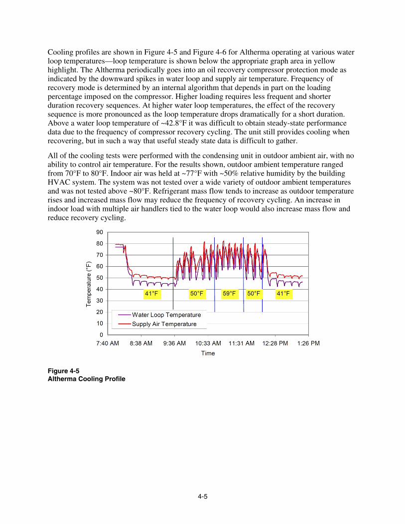
Cooling profiles are shown in Figure 4-5 and Figure 4-6 for Altherma operating at various water loop temperatures—loop temperature is shown below the appropriate graph area in yellow highlight. The Altherma periodically goes into an oil recovery compressor protection mode as indicated by the downward spikes in water loop and supply air temperature. Frequency of recovery mode is determined by an internal algorithm that depends in part on the loading percentage imposed on the compressor. Higher loading requires less frequent and shorter duration recovery sequences. At higher water loop temperatures, the effect of the recovery sequence is more pronounced as the loop temperature drops dramatically for a short duration. Above a water loop temperature of ~42.8°F it was difficult to obtain steady-state performance data due to the frequency of compressor recovery cycling. The unit still provides cooling when recovering, but in such a way that useful steady state data is difficult to gather.
All of the cooling tests were performed with the condensing unit in outdoor ambient air, with no ability to control air temperature. For the results shown, outdoor ambient temperature ranged from 70°F to 80°F. Indoor air was held at ~77°F with ~50% relative humidity by the building HVAC system. The system was not tested over a wide variety of outdoor ambient temperatures and was not tested above ~80°F. Refrigerant mass flow tends to increase as outdoor temperature rises and increased mass flow may reduce the frequency of recovery cycling. An increase in indoor load with multiple air handlers tied to the water loop would also increase mass flow and reduce recovery cycling.
Figure 4-5 Altherma Cooling Profile
4-5

Figure 4-6 Altherma Cooling Profile
Figure 4-7 through Figure 4-9 show results from a similar data set where steady-state operation is approximated such that some performance evaluation can be performed. With the water loop temperature set at 42.8°F, the supply air temperature coming out of the air handler reaches a steady-state of 50.6°F after approximately 1 hour. Supply air at 50.6°F is somewhat cooler than that produced by typical direct expansion (DX) air conditioners operating at similar air conditions. Saturated air with a dew point of 50.6°F has a moisture content of ~55 grains. Saturated air at 55°F, which is more typical of DX cooling coils at similar conditions, contains ~66 grains or 20% more moisture. The flexibility of setting the water loop temperature serves as a means for adjusting the sensible heat ratio (SHR) of the Altherma. Ability to adjust the SHR is a useful attribute when applying an HVAC system. Air conditioning is inherently a two part problem comprised of 1) sensibly cooling air and 2) dehumidifying air. Current, single-speed direct expansion (DX) vapor compression air conditioning systems found in commercial and residential buildings provide both. Their ability to do either is captured in the SHR, which is the sensible cooling divided by the total (sensible + latent) cooling of a system. The sensible heat ratio is generally fixed according to the mechanical details of a particular system, though it depends somewhat on the surrounding air conditions.
Single-speed DX equipment is being pushed to higher SEER levels mainly by increasing coil surface area, which has the effect of raising the sensible heat ratio; i.e. lessening dehumidifying ability. Higher SHR’s in combination with ever more insulated buildings creates a combination where lower sensible load is being cooled by equipment with greater sensible cooling abilities. The opposite is true for the latent component. Latent loads remain unchanged, or even increase with tighter insulation but mechanically forced ventilation air; and high SHR equipment is less capable of removing moisture. The result is conditioned building space that has high relative humidity, but that must be maintained at relatively low temperatures to offer a feeling of comfort.
The classic solution to the problem of having a SHR higher than that demanded by the load was to over-cool and then re-heat the air. Though very effective, re-heat systems are energy intensive
4-6

and defeat the purpose of taking other energy saving actions, such as insulating or using high SEER equipment.
A variable speed DX system, and in particular a variable speed hydronic system with water loop set point control, offers a different approach by allowing the SHR of the unit to be adjusted according to the needs of the building and the climate.
Figure 4-7 Steady-State Cooling
Figure 4-8 shows supply air temperature and air-side temperature drop across the air handler (return air temperature minus supply air temperature) for the portion of data with the water loop set at 42.8°F. The slight oscillation in temperature drop is likely a byproduct of fluctuations in the return air temperature due to cycling of the building HVAC system. Figure 4-9 shows power consumption for the same data set both including and excluding air handler fan power. “Altherma Power” excludes the ~260 Watts consumed by the air handler, while “System Power” includes it. The Altherma can be matched with a variety of indoor units, including those of other manufacturers, and the power draw characteristics of the selected fan coil units will be unique to each installation.
4-7
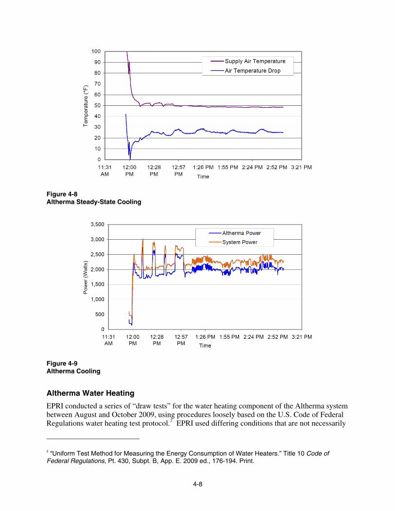
Figure 4-8 Altherma Steady-State Cooling
Figure 4-9 Altherma Cooling
Altherma Water Heating
EPRI conducted a series of “draw tests” for the water heating component of the Altherma system between August and October 2009, using procedures loosely based on the U.S. Code of Federal Regulations water heating test protocol.2 EPRI used differing conditions that are not necessarily
2 “Uniform Test Method for Measuring the Energy Consumption of Water Heaters.” Title 10 Code of Federal Regulations, Pt. 430, Subpt. B, App. E. 2009 ed., 176-194. Print.
4-8

held within the prescribed bounds articulated in the federal standard. The draw test provides insight into how a water heater performs when nearly depleted of hot water from a single, continuous water draw event. Hot water is drawn from the water tank at 3.0 (±0.2) gpm until the water outlet temperature decreases by 25°F from the maximum observed water outlet temperature. When the 25°F-decrease is reached, the water heater will be nearly depleted of its hot water supply, and the water draw is terminated. The water heater is then allowed fully reheat undisturbed.
The draw tests were conducted using Altherma’s heat pump only mode (i.e. no resistive elements were enabled) and a 120°F water tank temperature setting. Four draw tests were executed, and a summary of each draw test is provided in Table 4-1. The four draw tests are ordered based on average outdoor temperatures during each test, from lowest to highest outdoor temperature.
Table 4-1 Summary of Draw Test Results for Altherma Water Heater
Test Number 1 2 3 4
Test Duration (hours) 1.9 1.7 1.5 1.5
Indoor Temp, Avg (°F) 71.9 71.2 73.9 73.0
Indoor Humidity, Avg (%RH) 45.7 45.6 44.2 47.4
Outdoor Temp During Reheat, Avg (°F) 68.5 73.2 78.2 80.9
Outdoor Humidity During Reheat, Avg (%RH) 88.1 76.1 60.7 56.9
Water Draw Flow Rate, Avg (gpm) 2.7 3.0 3.0 3.0
Water Draw Inlet Temp, Weighted Avg (°F) 54.6 58.2 58.8 59.0
Water Draw Outlet Temp, Weighted Avg (°F) 119.3 119.4 119.6 120.1
Water Draw Volume (gal) 48.9 49.3 47.9 46.7
Water Draw Energy (ton-h) 2.2 2.1 2.0 2.0
Electric Power Reheat, Avg (kW) 1.7 1.7 1.8 1.6
Electric Power Reheat, Max (kW) 4.4 2.9 4.3 3.0
Electric Energy Reheat (kWh) 3.0 2.6 2.4 2.2
Overall COP (Btu/Btu) 2.6 2.8 3.0 3.2
As shown in Table 4-1, the water drawn out of the tank for each draw test is generally between 47 and 49 gallons. The average power draw during the reheat period was consistent among the four draw tests (1.6kW to 1.8kW), but the maximum power draw varied quite largely (2.9kW to 4.4kW) with no apparent correlation to average outdoor temperature. The overall COP (quotient when “energy out” is divided by “energy in”) increases with increasing average outdoor temperature, as should be expected with an outdoor heat pump unit. A graph showing the trend of overall COP verses average outdoor temperature is shown in Figure 4-10.
4-9

2.59
2.83
3.02
3.21
2.0
2.2
2.4
2.6
2.8
3.0
3.2
3.4
3.6
3.8
4.0
66 68 70 72 74 76 78 80 82 84Average Outdoor Air Temp (°F)
Ove
rall
CO
P (B
tu/B
tu)
Overall COP (Btu/Btu)
Figure 4-10 Draw Tests Overall COPs for Varying Outdoor Temperatures
The Altherma power and water draw profile for the first draw test is shown in Figure 4-11. The water tank inlet and outlet temperatures are plotted only when water flow is present. The power profile data includes the total system power: compressor, condenser fan, water pump, and controls.
0
1
2
3
4
5
0:00 0:30 1:00 1:30 2:00Time (h:m)
Pow
er (k
W)
0
30
60
90
120
150
Tem
pera
ture
(°F)
Water Heater Power (W) Water Draw Inlet Temp (°F)Water Draw Outlet Temp (°F)
Water draw period (green dotted boundary)
Figure 4-11 Draw Test 1 - Power and Water Draw Profile
4-10

5 IMPLICATIONS/CONCLUSIONS The Altherma is a flexible system with relatively high grade (high temperature) heating or cooling for a residence or small commercial facility. Nominal capacity is 36,000 Btu/hr, but depending on conditions this can be exceeded and variable speed components allow for continuous and efficient part-load operation.
The EPRI setup was not designed as a controlled environmental rating test and components such as the indoor air handler were not selected to maximize performance. A variable speed hydronic heat pump like the Altherma does not necessarily fit into standard rating categories like most unitary equipment and it is somewhat difficult to properly characterize comparative performance with single-speed equipment.
This type of small air-source equipment is appropriate for use in residential and commercial applications, particularly where space heating/cooling and water heating are required. The hydronic loop serving interior space allows for distributed delivery of conditioned air and hence distributed control of indoor temperature. Distributed control of indoor temperature, for instance to each room of a house, is not a feature typically seen with forced air systems except in high end commercial space employing variable air volume systems. Distributed temperature control improves comfort and potentially improves overall energy use by restricting heating/cooling delivered to occupied spaces. Unoccupied spaces can be set to a more energy favorable set point. By having the entire system, including thermostatic controls, as a product of one manufacturer, it is simpler to use built-in software to allow greater control flexibility. In order to realize the full benefits of energy management, or energy budgeting, an energy distribution system must act as the foundation through which energy is delivered. The Altherma is a step in that direction by combining water heating and space conditioning and providing heat/cool in a highly flexible manner.
Altherma can be installed for new construction and as a retrofit. Ease of retrofit is dependant on the nature of a structure. Replacing a traditional ducted arrangement in a residence with the hydronic Altherma, would require installing a new piping network. However, Altherma can be integrated with an existing forced air distribution setup.
Variable speed allows Altherma to control the water loop temperature, which in turn allows for control of the supply air temperature. For heating, air can be delivered at a relatively high temperature, in excess of 120°F, akin to what a gas furnace delivers, or at a lower, most efficient temperature, more in line with what traditional single-speed heat pumps deliver. In cooling mode, control of the chilled water temperature gives the user fine control of the sensible heat ratio (SHR) which allows for greater removal of humidity when necessary. Higher water loop temperature and in turn higher supply air temperature and SHR can be chosen to maximize system efficiency. At the lower range of water loop set-point, ~41-45°F, supply air temperature is maintained below 50°F with ~77°F return air. Single speed equipment does not offer such flexibility.
Potential exists, though it has not been attempted to date, to use the centralized control and distributed nature of an installation to allow for temporary curtailment of power use—demand
5-1

reduction. Similar strategies are proposed for commercial VRF systems and look to have promise. The advantage over more traditional relay-drop-off methods is that percentage power draw reductions can be called for, minimizing the noticeable impact to the consumer, while still providing the demand response need of the utility.
5-2

6 RECOMMENDATIONS FOR FUTURE RESEARCH AND ACTIVITIES Continuing research on advanced air source heat pumps and associated space conditioning technologies should focus on 1) defining the thermal requirements of traditionally separated processes within a building system, 2) understanding the abilities of currently available and near-term equipment for meeting the requirements and 3) to describe the economic drivers of new technology adoption.
The testing of the Altherma system detailed in this report is a hybrid laboratory/field test where significant instrumentation was placed on a system in a semi-controlled environment. Because the Altherma is a flexible system which can be installed in a variety of configurations, it or similar systems are well characterized by retrofit field testing, in particular where good baseline can be either pre-measured or measured on a similar building in parallel. Many of the efficiency and comfort benefits from these variable systems come from the dynamic ability to adjust output to load demand, which is unique to a particular location. Laboratory testing characterizes steady-state performance over a variety of operating conditions, but it is less able to capture benefits of dynamic capacity to meet dynamic load.
Altherma, again because of its variable speed nature, allows greater capacity to be maintained at the lower end of outdoor ambient temperature of the heat pump operating range, offering equipment that can be used at higher latitude. Toward this end, further product offerings by Daikin and perhaps others, are being developed that optimize these variable speed heat pumps for northern latitudes where traditionally air-source heat pumps are not practical. Extending the geographical range of air-source heat pumps while maintaining efficiency with aggregate COP in the 2.5+ range would provide a method for decreasing overall energy use in that marginal latitude zone.
From the standpoint of energy budgeting, prescribed methods need to be developed for analyzing the various energy use or energy production profiles of the equipment used in or for buildings. This includes, but may not be limited to space heating, space cooling, domestic water heating and process water heating. Each of these and other processes has a set of parameters describing the energy requirements, for example, the amount of energy required, the rate of delivery and degree of that energy. Efficient use of overall energy to a building will maximize the exchange of energy between these various processes and equipment doing the energy exchange must be capable of meeting the boundary parameters.
6-1


Export Control Restrictions
Access to and use of EPRI Intellectual Property is granted with the specific understanding and requirement that responsibility for ensuring full compliance with all applicable U.S. and foreign export laws and regulations is being undertaken by you and your company. This includes an obligation to ensure that any individual receiving access hereunder who is not a U.S. citizen or permanent U.S. resident is permitted access under applicable U.S. and foreign export laws and regulations. In the event you are uncertain whether you or your company may lawfully obtain access to this EPRI Intellectual Property, you acknowledge that it is your obligation to consult with your company’s legal counsel to determine whether this access is lawful. Although EPRI may make available on a case-by-case basis an informal assessment of the applicable U.S. export classification for specific EPRI Intellectual Property, you and your company acknowledge that this assessment is solely for informational purposes and not for reliance purposes. You and your company acknowledge that it is still the obligation of you and your company to make your own assessment of the applicable U.S. export classification and ensure compliance accordingly. You and your company understand and acknowledge your obligations to make a prompt report to EPRI and the appropriate authorities regarding any access to or use of EPRI Intellectual Property hereunder that may be in violation of applicable U.S. or foreign export laws or regulations.
The Electric Power Research Institute Inc.,
(EPRI, www.epri.com) conducts research and
development relating to the generation, delivery
and use of electricity for the benefit of the public.
An independent, nonprofit organization, EPRI
brings together its scientists and engineers as well
as experts from academia and industry to help
address challenges in electricity, including
reliability, efficiency, health, safety and the
environment. EPRI also provides technology, policy
and economic analyses to drive long-range
research and development planning, and supports
research in emerging technologies. EPRI’s
members represent more than 90 percent of the
electricity generated and delivered in the United
States, and international participation extends to 40
countries. EPRI’s principal offices and laboratories
are located in Palo Alto, Calif.; Charlotte, N.C.;
Knoxville, Tenn.; and Lenox, Mass.
Together…Shaping the Future of Electricity
© 2009 Electric Power Research Institute (EPRI), Inc. All rights reserved. Electric Power Research Institute, EPRI, and TOGETHER…SHAPING THE FUTURE OF ELECTRICITY are registered service marks of the Electric Power Research Institute, Inc.
1017887
Electric Power Research Institute 3420 Hillview Avenue, Palo Alto, California 94304-1338 • PO Box 10412, Palo Alto, California 94303-0813 • USA
800.313.3774 • 650.855.2121 • [email protected] • www.epri.com