performance components - integrated environmental …€¦ · performance components ......
TRANSCRIPT

Integrated Environmental Solutions
Performance Components

Performance Components
VE 2012 Performance Components 2
Contents
1. Introduction ......................................................................................................................................... 3
2. Importing components from library ..................................................................................................... 3
2.1. Accessing the Add Components from Library dialog ................................................................... 3
2.1.1. Main VE toolbar and menu .................................................................................................... 4
2.1.2. Component Modeller ............................................................................................................. 4
2.1.3. On creation of a new project (File menu: New) ..................................................................... 5
2.2. Add components from library ....................................................................................................... 5
2.3. Placing components in the model ................................................................................................ 6
2.3.1. Placing Object Components .................................................................................................. 6
2.3.2. Placing Space Component: Windcatcher .............................................................................. 7
2.3.3. Finalizing Space Component: Windcatcher ........................................................................... 8
2.3.4. Finalize Space Component: Dynamic Room Group Creation ............................................... 9
3. Manually Defining a Component ....................................................................................................... 10
3.1. Defining a Windcatcher .............................................................................................................. 10
3.2. Defining ducts ............................................................................................................................. 10
4. FAQ ................................................................................................................................................... 11
4.1. How do I remove a Windcatcher after it has been finalized ....................................................... 11
4.2. How do I define thermal data to a manually created component ............................................... 14

Performance Components
VE 2012 Performance Components 3
1. Introduction
Performance components help architects and consultants deliver low maintenance, energy efficient
designs within the built environment. Pre-built manufacturer assemblies, such as ‘Monodraught
Windcatchers’, can be imported to the Virtual Environment, providing a mix of geometry and thermal
data as per manufacturer specification. Components fall into three distinct categories:
Object
Space
Panel
Object components are components that can be placed within rooms. Traditionally these have been
used for visualisation purposes within applications such as Radiance and also as CFD heat sources
for use in Microflo.
Space components are components that when placed and finalized, become part of the actual
building model; Windcatchers being the prime example of this. The user places the Windcatcher
component accordingly and then chooses the option “Finalize”. It’s at this point that the component
geometry is merged/formed into the building model. This pre-built Windcatcher has been assembled
in accordance with manufacturer specification and can now be simulated without further user
intervention. Essentially, this drag and drop feature allows the user to quickly model items, such as
Windcatchers efficiently and accurately.
Panel components (not available until late 2012) are components that can be placed on a surface.
An example would be a PV panel. As with space components, these can be built as per manufacturer
or user specification and then placed onto a selected surface in a similar manner to that of the window
placement tool already available in the VE.
2. Importing components from library
The virtual environment contains many pre-built components including Monodraught’s Windcatcher
range. These components are readily available to be used within any given project, the user is simply
required to select and import into their project.
2.1. Accessing the ‘Add Components from Library’ dialog
There are several routes available to the user to import pre-built performance components.

Performance Components
VE 2012 Performance Components 4
2.1.1. Main VE toolbar and menu
Both these options behave identically and invoke the “Add Components From Library” dialog.
2.1.2. Component Modeller

Performance Components
VE 2012 Performance Components 5
This option also opens “Add Components From Library” dialog.
2.1.3. Creation of a new project (File menu: New)
Note: this option differs from those above as this does not give the user the option of being selective
(unlike the options above). Instead, this option imports the entire selected library.
2.2. Add components from library
The “Add components from library” dialog enables the user to import pre-built components from one
or more libraries.
Library selector
This provides a drop list of available pre-built
libraries
Component List
This provides a drop
list of available pre-
built libraries. The
user can scroll the
list to view items
and by using the
asociated tick
boxes, select those
they wish to import
Product Data Sheet (optional)
Provides link to manufacturer product
data sheet for the selected component.
Should this not appear as shown above,
then none have been specified for
selected product.
Import Checked
components
As the name suggests,
this button shall import
the checked
components. When no
item is selected OR
during import, this
button shall be disabled.
The preview tab provides an option to view the component in 3D wire frame mode.

Performance Components
VE 2012 Performance Components 6
Note: importing a performance component from will also import associated data such as
constructions, schedules/profiles, templates, systems etc.
2.3. Placing components in the model
Once the user has added components to their library, either by importing (as shown above), or by
manually creating them, these can then be added to the building model.
There are two buttons on the main toolbar used for component operations, both highlighted below.
Left to right…
Place Component – available when the user has selected component to place (detailed
below).
Finalize Component – available when the user has selected a placed component. This
option forms properly bound spaces form the component and should only be used for “Space
Components”. In other words, for a component that is to become part of the building model
geometry. An example of this would be Monodraught Windcatchers.
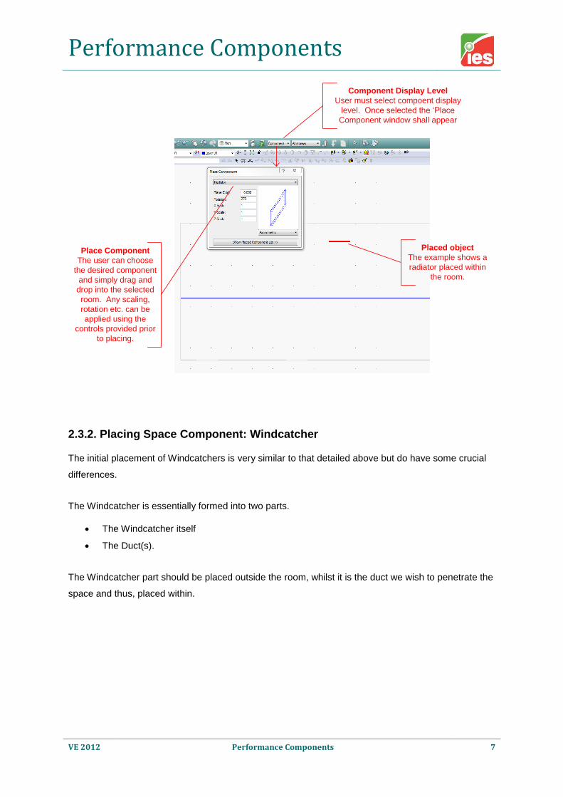
2.3.1. Placing Object Components
Object components are the traditional VE method for component placement. The user should firstly
move into body level of decomposition and then select the component display level.
Performance Components
VE 2012 Performance Components 7
Component Display Level
User must select compoent display
level. Once selected the ‘Place
Component window shall appear
Place Component
The user can choose
the desired component
and simply drag and
drop into the selected
room. Any scaling,
rotation etc. can be
applied using the
controls provided prior
to placing.
Placed object
The example shows a
radiator placed within
the room.
2.3.2. Placing Space Component: Windcatcher
The initial placement of Windcatchers is very similar to that detailed above but do have some crucial
differences.
The Windcatcher is essentially formed into two parts.
The Windcatcher itself
The Duct(s).
The Windcatcher part should be placed outside the room, whilst it is the duct we wish to penetrate the
space and thus, placed within.

Performance Components
VE 2012 Performance Components 8
Windcatcher components may have variable length ducts; the ‘Duct Length’ field highlighted above
allows the user to vary ducts lengths at time of placement.
Note: the small component Viewport is now drawn with a white background and the default view is
Axonometric - the "Duct" is drawn in red.
If the VE detects that Windcatcher is not placed correctly, then the user shall be presented with a
suitable warning. Typical causes may be that the Windcatcher part is placed within the room (should
be fully outside), or the component is not fully over the room. In this scenario, adjusting the ‘Plane’
accordingly would solve this. However, perhaps the easiest solution would be to use the move
options from the main toolbar.
Tip: Before choosing “Finalize component” (detailed below) ensure that the component is placed
correctly. Once finalized, this component automatically becomes part of the model geometry.
2.3.3. Finalizing Space Component: Windcatcher
When the user chooses to finalize the component, the process takes the component and
automatically generates the model geometry, cutting the duct through the penetrating space etc.
Before performing this action, the user should take care to ensure that they have placed the
component in the correct position before continuing.

Performance Components
VE 2012 Performance Components 9
Finalize Component
The Finalize toolbar button only becomes available
when the user has selected a component.
Selected Component
The user must select
the component they
wish to “Finalize”.
Finalize will
automatically form the
model geometry from
the compoment,
transforming the
component into a
properly bound space
Once Finalized, the component is transformed into a group of bounded building model rooms. The
rooms that are formed via the ‘Finalize’ stage contain all thermal data as provided by the
manufacturer. Macroflo openings, control strategy, constructions etc. are all now exposed part of this
process.
2.3.4. Finalize Space Component: Dynamic Room Group Creation
Following the step above, room grouping schemes and associated room groups will automatically be
generated as follows:
1) A room grouping scheme containing ALL components of given category and type. For
example Windcatchers are defined as having a category “Space” and type “Windcatcher”. In
this case the scheme would be name “Space_Windcatcher”. This scheme would then contain
a separate room group for each different type.
Note: Should the user place and finalize n copies of a particular component, then all rooms of
these copies shall be placed within this single room group. This is repeated for each
subsequent type.
2) A room grouping scheme containing individual room groups for each component type. For
example, type = Windcatcher (as shown above) we therefore, have a room grouping scheme
Performance Components
VE 2012 Performance Components 10
named “Windcatchers”, however unlike item 1 above, this contains room groups for each
individual finalized component.
The dynamic grouping detailed above provides mechanism for the user to more easily manage their
building models and identify rooms within individual or groups of finalized components.
3. Manually Defining a Component
The user can manually create components using the component modeller application. The traditional
ModelIt drawing tools, also available in component modeller, can be used to create the component
geometry.
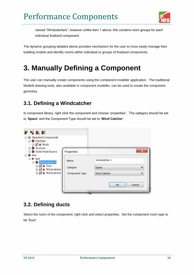
3.1. Defining a Windcatcher
In component library, right click the component and choose “properties”. The category should be set
to ‘Space’ and the Component Type should be set to ‘Wind Catcher’.
3.2. Defining ducts
Select the room of the component; right click and select properties. Set the component room type to
be ‘Duct’.

Performance Components
VE 2012 Performance Components 11
Note: Windcatchers must have defined “duct” zones as it is these zones that are “trimmed”. For
now, we assume that Windcatchers should contain 4 duct zones (this can also be 4 connected duct
zones i.e. 1 duct zone containing 4 constituent duct zones).
4. FAQ
4.1. How do I remove a Windcatcher after it has been
finalized
Zone with Windcatcher

Performance Components
VE 2012 Performance Components 12
Once the Windcatcher has been added to the zone the geometry of the zone has been changed, if
this is wrong and the "undo" is not a feasible option, then the next best possibility is to use the
"merge" option in the "Connect Spaces" dialog.
Zone without Windcatcher
The geometry of the Windcatcher, other than the "Duct" zone, can be deleted.
Performance Components
VE 2012 Performance Components 13
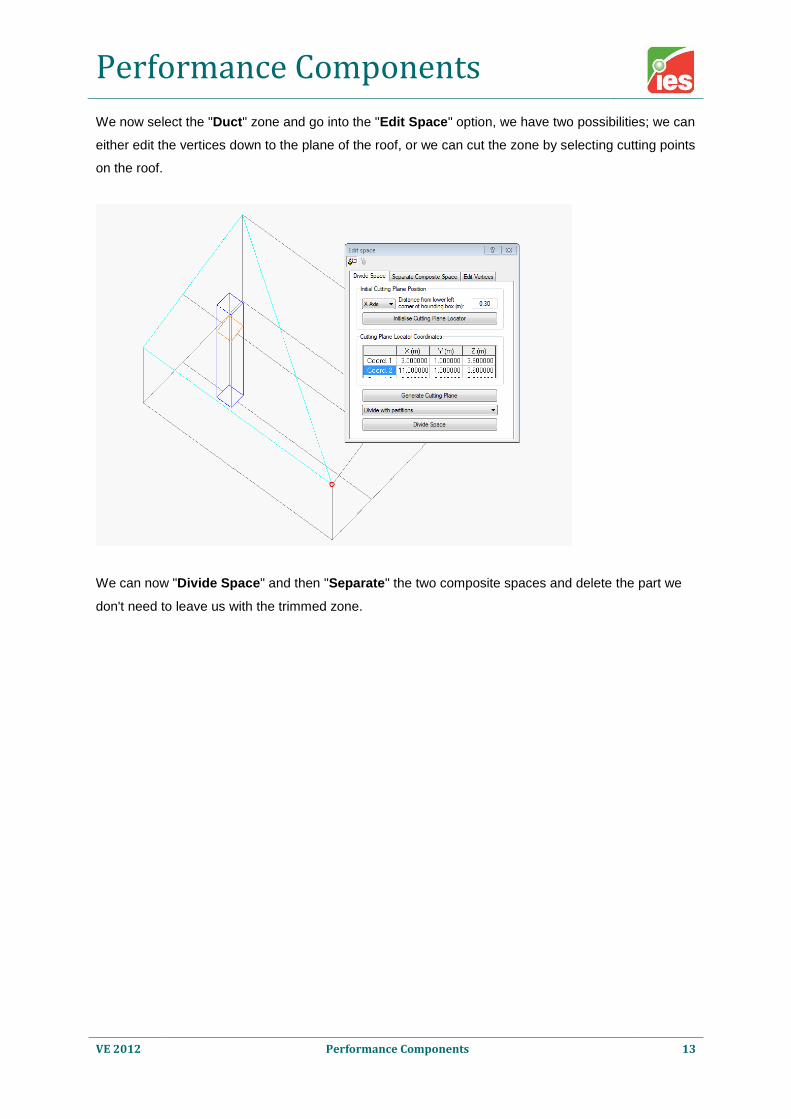
We now select the "Duct" zone and go into the "Edit Space" option, we have two possibilities; we can
either edit the vertices down to the plane of the roof, or we can cut the zone by selecting cutting points
on the roof.
We can now "Divide Space" and then "Separate" the two composite spaces and delete the part we
don't need to leave us with the trimmed zone.

Performance Components
VE 2012 Performance Components 14
If we now "merge" these two zones, we get back to the original zone.
4.2. How do I define thermal data to a manually created
component
Currently, the user must define this data after the component has been finalized. The ability to define
this data natively within components will be exposed in a future version.
Note: performance components imported from pre-defined libraries, such as, Monodraught
Windcatchers, come with all thermal data pre-defined.