performance evaluation of lower-energy energy storage ... · sae 2014 hybrid & electric vehicle...
TRANSCRIPT
NREL is a national laboratory of the U.S. Department of Energy, Office of Energy Efficiency and Renewable Energy, operated by the Alliance for Sustainable Energy, LLC.
Performance Evaluation of Lower-Energy Energy Storage Alternatives
for Full-Hybrid Vehicles
SAE 2014 Hybrid & Electric Vehicle Technologies Symposium La Jolla, California
February 11-13, 2014
Jeff Gonder, Jon Cosgrove and Ahmad Pesaran National Renewable Energy Laboratory (NREL)
Transportation and Hydrogen Systems Center (THSC) Project supported by the DOE Vehicle Technologies Office
NREL/PR-5400-61380
2
Motivation
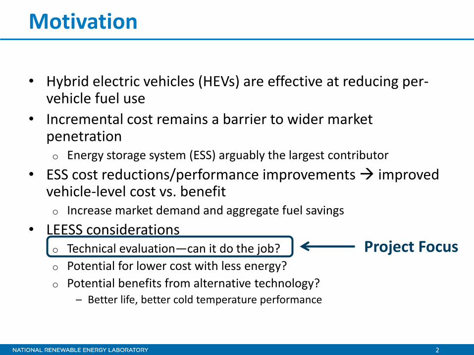
• Hybrid electric vehicles (HEVs) are effective at reducing per-vehicle fuel use
• Incremental cost remains a barrier to wider market penetration o Energy storage system (ESS) arguably the largest contributor
• ESS cost reductions/performance improvements improved vehicle-level cost vs. benefit o Increase market demand and aggregate fuel savings
• LEESS considerations o Technical evaluation—can it do the job? o Potential for lower cost with less energy? o Potential benefits from alternative technology?
– Better life, better cold temperature performance
Project Focus

3
Related Background Work: NREL Evaluation for GM of Replacing NiMH Batteries with Ultracapacitors in the 42-V Saturn Vue BAS HEV
• Motivation: Ucap potential for superior cycle life, cold temperature performance, and long-term cost reductions
• Bench tested Ucaps and retrofitted vehicle to operate in 3 configurations
BAS = belt alternator starter (“mild” HEV)
Photos by Jeff Gonder and Jason Lustbader, NREL
Findings: 42V HEV with ultracapacitors performed at least as well as the stock configuration with a NiMH battery

4
Additional Background: NREL Analysis for USABC of Full-HEV Fuel Savings Sensitivity to Energy Storage Size
USABC = United States Advanced Battery Consortium EES TT = The FreedomCAR/USDRIVE Electrochemical Energy Storage Technical Team
• USABC established targets and began supporting device developers o See: http://www.uscar.org/guest/article_view.php?articles_id=87 o Open to any ESS technology (very high power batteries, electrochemical double-
layer capacitors, or asymmetric supercapacitors)
• Results suggested power-assist HEVs can still achieve high fuel savings with lower energy and potentially lower-cost ESS – see: o Gonder, J.; Pesaran, A.; Howell, D.; Tataria, H. “Lower-
Energy Requirements for Power-Assist HEV Energy Storage Systems—Analysis and Rationale.” Proceedings of the 27th International Battery Seminar and Exhibit; Mar 15-18, 2010, Fort Lauderdale, FL. http://www.nrel.gov/docs/fy10osti/47682.pdf
• NREL performed simulations and analyzed test data in conjunction with an EES TT Workgroup o Re-evaluating ESS targets established in the late 1990s / early 2000s
5
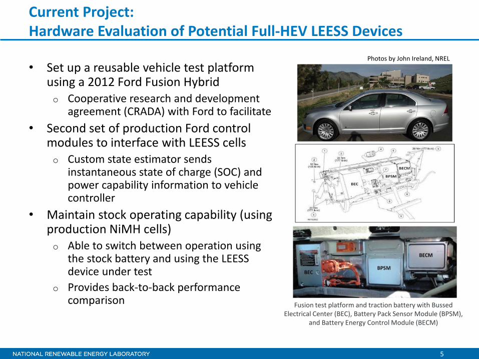
• Set up a reusable vehicle test platform using a 2012 Ford Fusion Hybrid o Cooperative research and development
agreement (CRADA) with Ford to facilitate • Second set of production Ford control
modules to interface with LEESS cells o Custom state estimator sends
instantaneous state of charge (SOC) and power capability information to vehicle controller
• Maintain stock operating capability (using production NiMH cells) o Able to switch between operation using
the stock battery and using the LEESS device under test
o Provides back-to-back performance comparison
Current Project: Hardware Evaluation of Potential Full-HEV LEESS Devices
Fusion test platform and traction battery with Bussed Electrical Center (BEC), Battery Pack Sensor Module (BPSM),
and Battery Energy Control Module (BECM)
Photos by John Ireland, NREL

6
Bench Testing of First LEESS under Evaluation
o Asymmetric storage device with battery and ultracapacitor-type characteristics
o 3.8 V max/cell, and doubled volumetric capacitance due to lithium doping
• Conversion pack sizing
*Based on fact sheet published by Idaho National Laboratory (INL): http://www1.eere.energy.gov/vehiclesandfuels/avta/pdfs/hev/batteryfusion4699.pdf **Assuming 175 V – 350 V maximum in-vehicle operating window
# of Cells Nominal Voltage Total Energy (Wh)
Stock Sanyo NiMH* 204 275 1,370 8 JSR 192 F LIC Modules 96 300 260**
• JSR Micro provided LIC modules
Figure courtesy of JSR Micro

7
JSR LIC Pack Characterization
• Bench cycling at multiple temperatures o Static capacity test o Hybrid pulse power
characterization (HPPC) o US06 drive profile
• Impedance 2–3x less than NiMH*
25°C, 8-Module HPPC Results
*Based on calculations from INL fact sheet OCV = open circuit voltage
Photo by John Ireland, NREL

8
US06 Stock Vehicle (NiMH) & LEESS (JSR LIC) Lab Comparison
Stock battery data courtesy of Argonne National Laboratory (ANL) chassis dynamometer testing US06 = aggressive drive cycle with high speeds and accelerations
Char
ging
(r
egen
erat
ive
brak
ing)
Di
scha
rgin
g (a
ssist
)

9
US06 Profile Comparison: Stock Battery (in vehicle) vs. JSR Micro LIC (in lab)
9
10
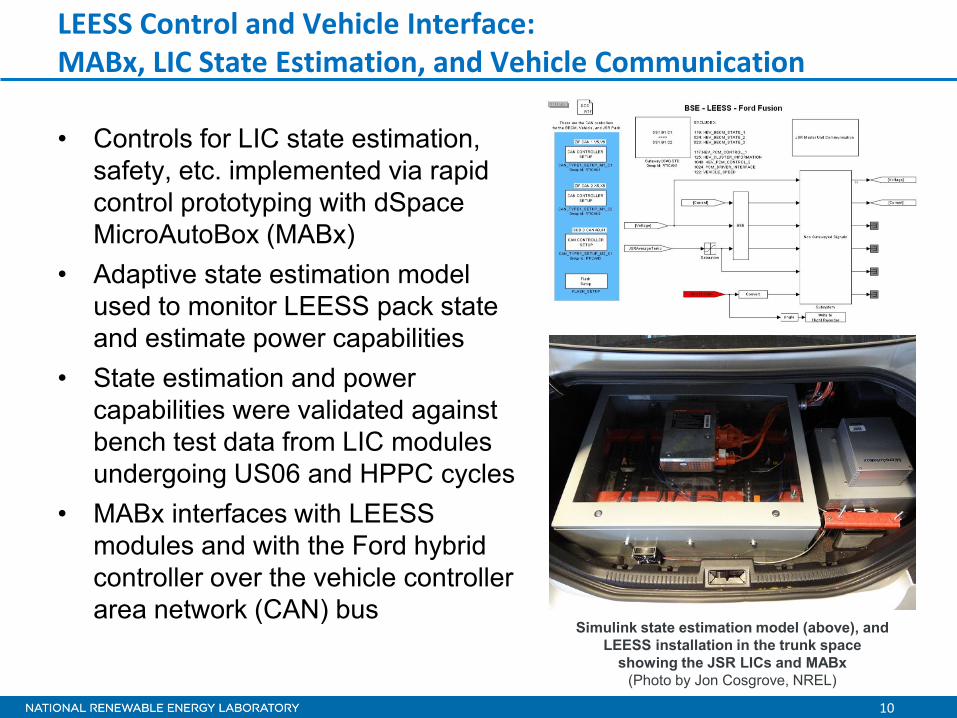
• Controls for LIC state estimation, safety, etc. implemented via rapid control prototyping with dSpace MicroAutoBox (MABx)
• Adaptive state estimation model used to monitor LEESS pack state and estimate power capabilities
• State estimation and power capabilities were validated against bench test data from LIC modules undergoing US06 and HPPC cycles
• MABx interfaces with LEESS modules and with the Ford hybrid controller over the vehicle controller area network (CAN) bus
LEESS Control and Vehicle Interface: MABx, LIC State Estimation, and Vehicle Communication
Simulink state estimation model (above), and LEESS installation in the trunk space
showing the JSR LICs and MABx (Photo by Jon Cosgrove, NREL)

11
In-Vehicle Comparison: 0–60 mph Accelerations* Stock Battery (NiMH) & LEESS (JSR LIC)
No significant difference found between acceleration times while in NiMH configuration vs. LEESS configuration
Photo by Petr Sindler, NREL
* Run with extra mass of both ESSs and at high altitude

12
In-Vehicle Comparison: Dynamometer Testing
• Performed standard drive cycles with vehicle in NiMH and LEESS configurations o Test cycles included:
– FTP/UDDS – HWFET – US06 – Cold (20°F) FTP
o Vehicle CAN traffic recorded using the MABx
• Testing details o CAN fuel rate calibrated to
bag measurements for comparisons
Test Schedule Dynamometer Facility
Photo by Jon Cosgrove, NREL
FTP/UDDS = Federal Test Procedure/Urban Dynamometer Driving Schedule (city testing) HWFET = Highway Fuel Economy Test

13
In-Vehicle Comparison: Dynamometer Testing Production NiMH vs. 3 LIC configurations • Evaluated several LIC scenarios in addition to the production configuration
o LIC-High: Energy constrained only by vehicle and device voltage limits o LIC-Med: Artificially reduced upper voltage limit to constrain energy o LIC-Low: Further reduced upper voltage limit for most constrained evaluation
Voltage (V)
Voltage Levels During UDDS Testing
14
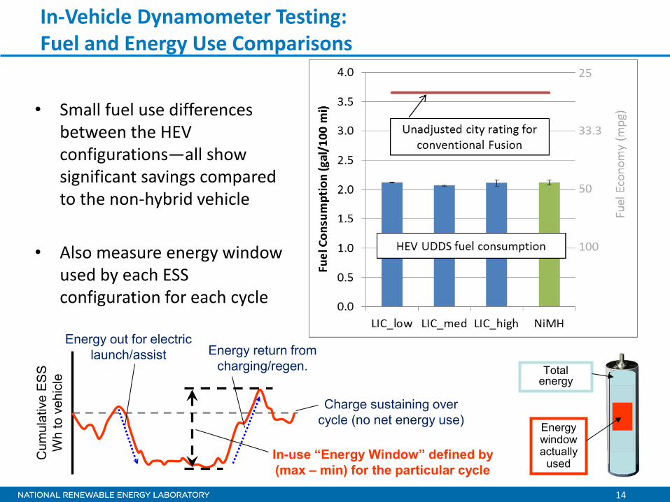
In-Vehicle Dynamometer Testing: Fuel and Energy Use Comparisons
• Small fuel use differences between the HEV configurations—all show significant savings compared to the non-hybrid vehicle
• Also measure energy window used by each ESS configuration for each cycle
Energy out for electric launch/assist
Cum
ulat
ive
ES
S
Wh
to v
ehic
le
Energy return from charging/regen.
Charge sustaining over cycle (no net energy use)
In-use “Energy Window” defined by (max – min) for the particular cycle
Total energy
Energy window actually
used
15
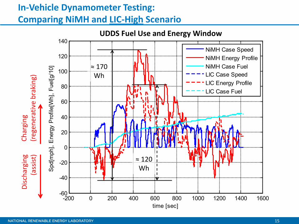
In-Vehicle Dynamometer Testing: Comparing NiMH and LIC-High Scenario
-200 0 200 400 600 800 1000 1200 1400 1600-60
-40
-20
0
20
40
60
80
100
120
140
time [sec]
Spd
[mph
], E
nerg
y P
rofil
e[W
h], F
uel[g
/10]
NiMH Case SpeedNiMH Energy ProfileNiMH Case FuelLIC Case SpeedLIC Energy ProfileLIC Case Fuel
UDDS Fuel Use and Energy Window Ch
argi
ng
(reg
ener
ativ
e br
akin
g)
Disc
harg
ing
(ass
ist)
≈ 170 Wh
≈ 120 Wh
16
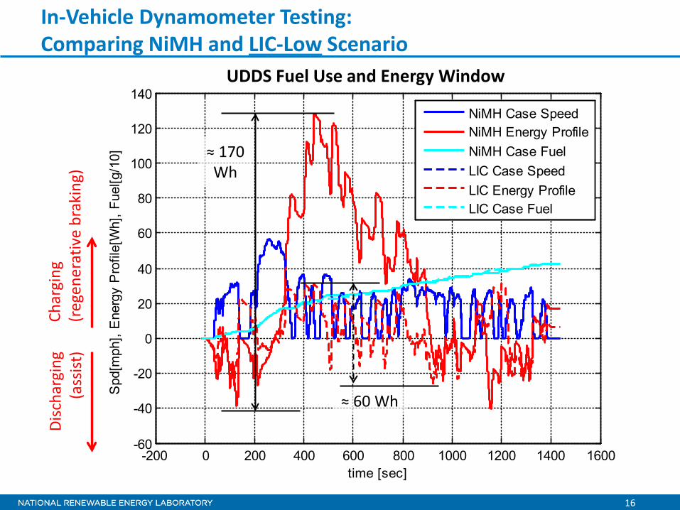
In-Vehicle Dynamometer Testing: Comparing NiMH and LIC-Low Scenario
UDDS Fuel Use and Energy Window Ch
argi
ng
(reg
ener
ativ
e br
akin
g)
Disc
harg
ing
(ass
ist)
-200 0 200 400 600 800 1000 1200 1400 1600-60
-40
-20
0
20
40
60
80
100
120
140
time [sec]
Spd
[mph
], E
nerg
y P
rofil
e[W
h], F
uel[g
/10]
NiMH Case SpeedNiMH Energy ProfileNiMH Case FuelLIC Case SpeedLIC Energy ProfileLIC Case Fuel
≈ 170 Wh
≈ 60 Wh

17
In-Vehicle Dynamometer Testing: Comparing NiMH and LIC-Low Scenario
UDDS Fuel Use and Energy Window Ch
argi
ng
(reg
ener
ativ
e br
akin
g)
Disc
harg
ing
(ass
ist)
-200 0 200 400 600 800 1000 1200 1400 1600-60
-40
-20
0
20
40
60
80
100
120
140
time [sec]
Spd
[mph
], E
nerg
y P
rofil
e[W
h], F
uel[g
/10]
NiMH Case SpeedNiMH Energy ProfileNiMH Case FuelLIC Case SpeedLIC Energy ProfileLIC Case Fuel
18
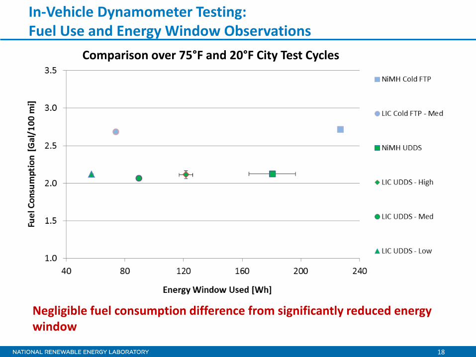
In-Vehicle Dynamometer Testing: Fuel Use and Energy Window Observations
Comparison over 75°F and 20°F City Test Cycles
Negligible fuel consumption difference from significantly reduced energy window

19
0 100 200 300 400 500 600 700 800
-80
-60
-40
-20
0
20
40
60
time [sec]
Spd
[mph
], E
nerg
y P
rofil
e[W
h], F
uel[g
/10]
NiMH Case SpeedNiMH Energy ProfileNiMH Case FuelLIC Case SpeedLIC Energy ProfileLIC Case Fuel
In-Vehicle Dynamometer Testing: Comparing NiMH and LIC-Low Scenario
HWFET Fuel Use and Energy Window Ch
argi
ng
(reg
ener
ativ
e br
akin
g)
Disc
harg
ing
(ass
ist)
≈ 110 Wh
≈ 50 Wh
20
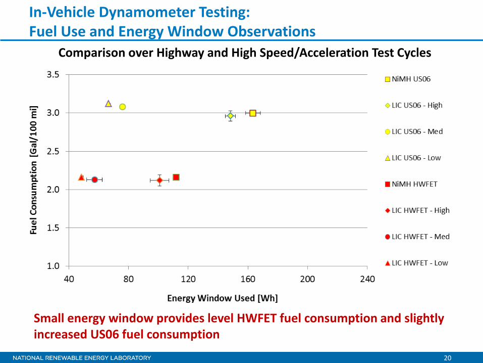
In-Vehicle Dynamometer Testing: Fuel Use and Energy Window Observations
Comparison over Highway and High Speed/Acceleration Test Cycles
Small energy window provides level HWFET fuel consumption and slightly increased US06 fuel consumption

21
0 100 200 300 400 500 600 700-150
-100
-50
0
50
100
time [sec]
Spd
[mph
], E
nerg
y P
rofil
e[W
h], F
uel[g
/10]
NiMH Case SpeedNiMH Energy ProfileNiMH Case FuelLIC Case SpeedLIC Energy ProfileLIC Case Fuel
In-Vehicle Dynamometer Testing: Comparing NiMH and LIC-Low Scenario
US06 Fuel Use and Energy Window
Char
ging
(r
egen
erat
ive
brak
ing)
Di
scha
rgin
g (a
ssist
)
22
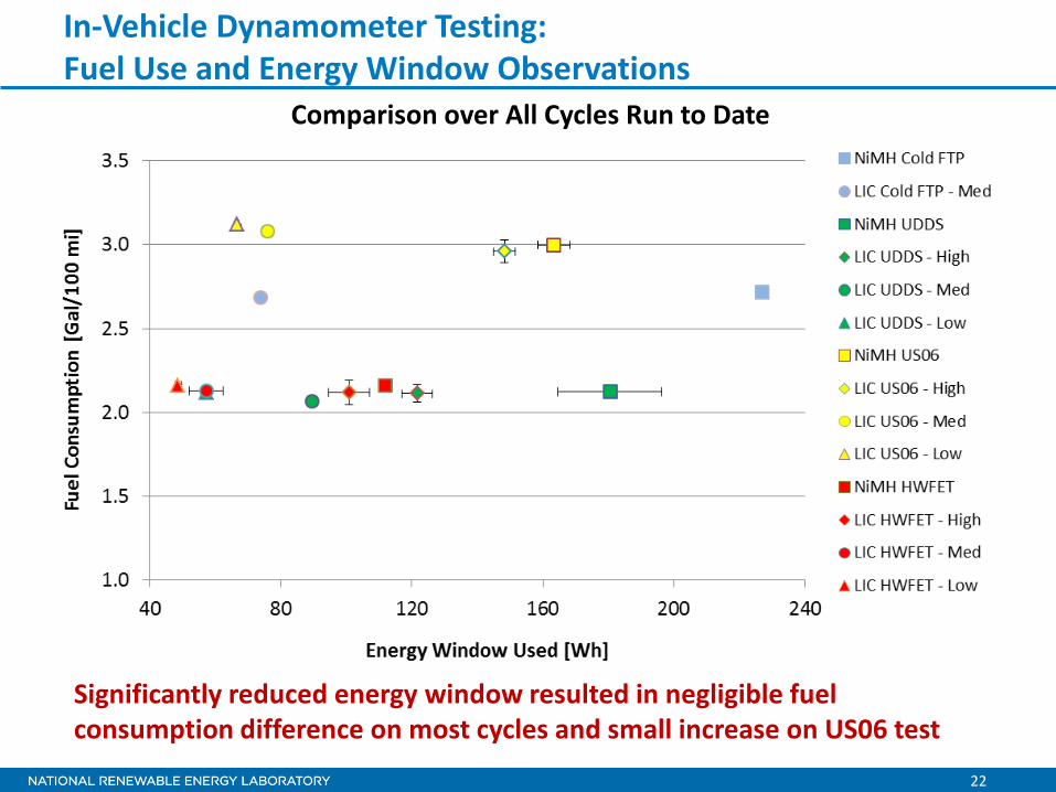
In-Vehicle Dynamometer Testing: Fuel Use and Energy Window Observations
Comparison over All Cycles Run to Date
Significantly reduced energy window resulted in negligible fuel consumption difference on most cycles and small increase on US06 test
23
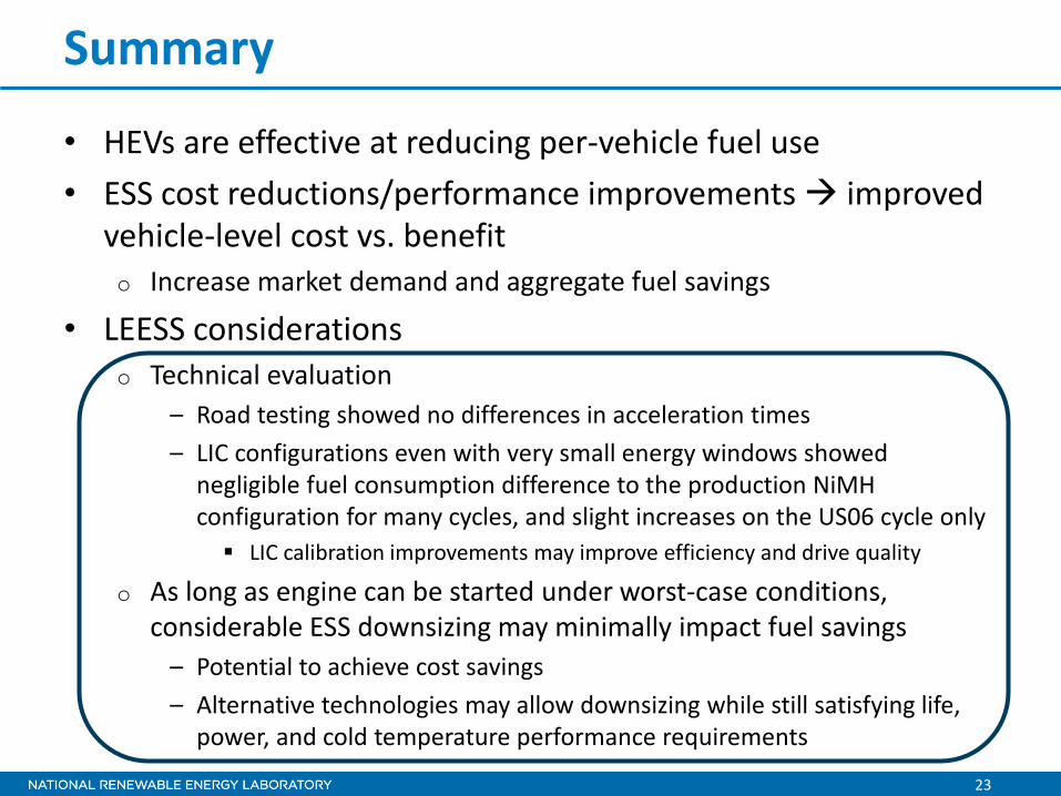
Summary
• HEVs are effective at reducing per-vehicle fuel use • ESS cost reductions/performance improvements improved
vehicle-level cost vs. benefit o Increase market demand and aggregate fuel savings
• LEESS considerations o Technical evaluation
– Road testing showed no differences in acceleration times – LIC configurations even with very small energy windows showed
negligible fuel consumption difference to the production NiMH configuration for many cycles, and slight increases on the US06 cycle only LIC calibration improvements may improve efficiency and drive quality
o As long as engine can be started under worst-case conditions, considerable ESS downsizing may minimally impact fuel savings
– Potential to achieve cost savings – Alternative technologies may allow downsizing while still satisfying life,
power, and cold temperature performance requirements
24
Potential Next Steps
• Wrap up JSR LIC testing o 95°F SC03 for air conditioning comparison case o Very cold (e.g., -10°F ≈ -23°C) operation
• Bench testing followed by in-vehicle evaluation with additional LEESS devices o Next system will be ultracapacitor modules
• Consider possible changes if vehicle designed around a LEESS device – e.g., higher power motor
• Combine evaluation results with supplier cost estimates to refine business case assessment

25 25
Acknowledgments
• JSR Micro o Providing modules for evaluation o Related technical information and support
• Ford Motor Company o CRADA facilitating vehicle conversion
• U.S. Department of Energy o Cost-shared support between two Vehicle Technologies Office
activities – Energy Storage (ES) – Vehicle Systems Simulation and Testing (VSST)
• USABC o Collaborated on precursor analysis to this effort and established
LEESS performance targets for power-assist HEVs • Maxwell Technologies
o Providing double-layer capacitors as next system to test