performance of an 8-path gas ultrasonic meter with and...
TRANSCRIPT

Performance of an 8-path gasultrasonic meter with andwithout flow conditioning
Dr Gregor BrownCaldon Ultrasonics
Cameron

Introduction
• Brief history of the Caldon ultrasonic meters
• Why 8-paths?
• Additional features of the Caldon LEFM 380Ci 8-path gas USM
• Testing performance to the requirements of theISO, OIML and AGA standards
• 4-path and 8-path results presented and comparedwith and without flow conditioning

History of Caldon meters
• 1965
– LEFM (Leading Edge Flow Meter) ultrasonictechnology is developed by WestinghouseElectric Corporation
• 1971
– Patent granted to Westinghouse for the firstchordal multipath meter design using Gaussianintegration

History of Caldon meters
• 1975 – Nuclear Industry
– Prairie Island unit 2 PWR
– Primary reactor coolant loop, 30-inch 4-path meter

History of Caldon meters
• 1976 – Petroleum Industry
– LEFM’s installed on the TransAlaska pipeline
– 23 off 48-inch, 4-path meters

History of Caldon meters
• 1989
– LEFM technology acquired by Caldon Inc.
– Primary focus on applications in the nuclearindustry
• 1999
– New line of petroleum products launched,designed specifically to meet the requirementsfor custody transfer
– 8-path liquid meters added to range

Chordal path design
• Gaussian Integration
– Johann Carl Friedrich Gauss (1777–1855)
• General mathematical techniquefor accurately integrating afunction with a limited number ofinputs
• Does not assume fully developedor symmetrical flow
• Does not rely on empiricalmodelling or CFD analysis of alimited number of conditions
If it’s that good why areflow conditioners used?

Only single paths are used at eachchord location

Westinghouse patents filed 1968, 1975

British Gas (BG) patent filed 1986

To obtain the full benefits of the Gaussianintegration technique, additional paths
are required

Caldon 8-path design

• Non-axial flow components (swirl) result in systematicerrors in individual path velocities
The effects of swirl
Actual velocity
Upstream transducer Downstream transducer
Axial component (wanted)
Transversecomponent(unwanted)
Measured velocity

Upstream transducer Downstream transducer
Swirl
• When dealing with non-axial flow we alsohave to consider the path orientation
+
-

Upstream transducer Downstream transducer
Swirl
• Crisscrossed paths behave differently toparallel paths
+
+

Upstream transducer Downstream transducer
Swirl
• With single plane or criss-crossing arrangements,swirl only cancels when perfectly centred
+
-
+

• With a planar arrangement, swirl onlycancels when perfectly centred
Upstream transducer Downstream transducer
4-path, planar (Westinghouse) configuration
+
-
+
-

4-path, planar (Westinghouse) configuration
• 60 degree path angle, swirl error = 0.45 %
+
-+
-0.80
0.85
0.90
0.95
1.00
1.05
1.10
-1 -0.8 -0.6 -0.4 -0.2 0 0.2 0.4 0.6 0.8 1
No
rmali
sed
velo
cit
y
Path radial position
Profile without swirl
4-path meter (single-plane)

Upstream transducer Downstream transducer
4-path, non-planar (BG) configuration
• In this case swirl cancelation relies oncombination of dissimilar chords
+
-
-
+Offset

0.80
0.85
0.90
0.95
1.00
1.05
1.10
-1 -0.8 -0.6 -0.4 -0.2 0 0.2 0.4 0.6 0.8 1
No
rmali
sed
velo
cit
y
Path radial position
Profile without swirl
4-path criss-crossed meter
+
--
+
4-path, non-planar (BG) configuration
• 60 degree path angle, swirl error = -1.09 %

Eight-path Caldon 280Ci (liquid) / 380Ci (gas)
• Designed for swirl immunity
• Flow conditioning not required
+
-
-
+
+
-
+-

How the crossed paths work
• Two crossing paths are placed precisely ineach chordal plane
+
-
-
+
+
-
+-
Paths 1 and 5

How the crossed paths work
Actual velocity
Axial component (wanted)
Transverse component (unwanted)
Measured velocity
Path 1 Path 5
Path 1 + Path 5
Path 1 + Path 5
2
Key:
=

Eight-path crossed plane design
• Swirl error = 0 %
0.80
0.85
0.90
0.95
1.00
1.05
1.10
-1 -0.8 -0.6 -0.4 -0.2 0 0.2 0.4 0.6 0.8 1
No
rmali
sed
velo
cit
y
Path radial position
8-path meter
Paths 1 to 4
Paths 5 to 8 +
--
+
+-
+-

Is it better to use a 4-path meter with a flowconditioner or an 8-path design to reduce
the effects of swirl?

Flow conditioners can become blocked

Flow conditioners
• If well maintained or protected by a filter flowconditioners reduce swirl and asymmetry butdo not completely eliminate it
• To demonstrate this I will refer to two verywell known sets of ultrasonic meter industrysponsored research data

Gas Research Institute MRF @ SwRi, USA
• 4, 5 and 6 path meters meters tested downstreamof bends, with and without flow conditioning
• Results below for 5D – CPA – 10D between bendsand meter, flow weighted mean error relative tostraight pipe calibration
CPA @ 10DSingle Elbow Elbows in-plane Elbows out-of-plane
0 90 0 90 0 90
Daniel -0.15 -0.13 0.03 0.04 0.23 -0.3
Instromet 0.30 0.30 0.43 0.50 0.36 0.33
FMC 0.02 0.02 -0.18 -0.14 -0.42 -0.64
0.3 % - 0.3 %- 0.64 %
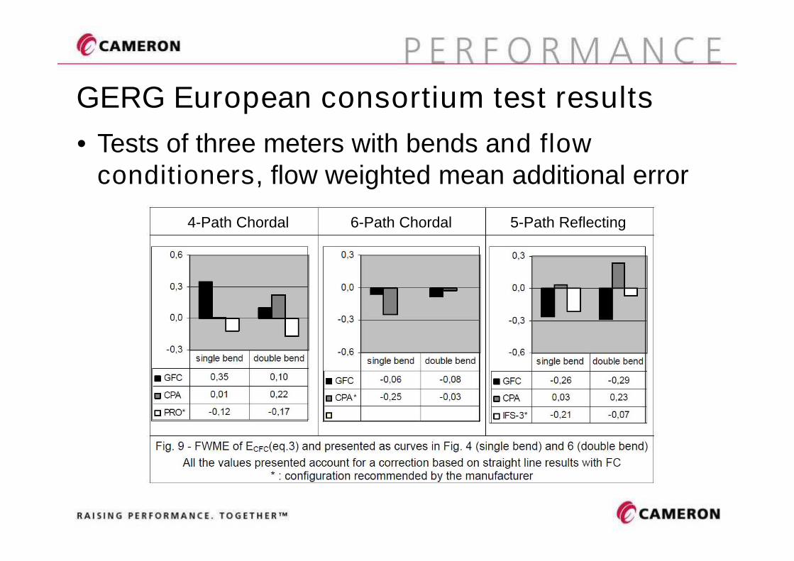
GERG European consortium test results
• Tests of three meters with bends and flowconditioners, flow weighted mean additional error
4-Path Chordal 6-Path Chordal 5-Path Reflecting

Additional features of the Caldon design
• Unique transducer arrangement
• Internal coating

Caldon transducer experience
• Many years of operation in nuclearapplications at up to +235 deg C
• LNG applications at -161 deg C

Manifold Removal
Transducers removable from pressure retainingtitanium housings in meter body – no blow downor special extractor tools required
Transducer configuration

Adhesion resistant proprietary coating
• Meter body and the transducer housings arecoated to aid preservation of calibration conditions

Is it better to use a 4-path meter with a flowconditioner or an 8-path design to reduce
the effects of swirl?
TEST RESULTS

Installation effect testing
• 8-path full-bore Caldon LEFM 380Ci gasflow meter
• 12-inch meter
• Tests performed at CEESI Iowa
• Part of the overall suite of tests the meterhas been undergoing to demonstratecompliance with ISO, AGA and OIMLstandards

Installation effect testing
• All tests witnessed by NMi of theNetherlands
• 8-path meter performed in compliance withOIML 0.5 class performance withoutrequiring a flow conditioner
• Results presented here for single anddouble bends, with and without flowconditioning

Installation changes for each disturbance
• 5D
• 15D
• CPA

Results and analysis
• 8-path data can also be broken down intofour different 4-path arrangements
8-path
Plane A Plane B BG 1 BG 2

Straight pipe baseline

-25% -20% -15% -10% -5% 0% 5% 10% 15% 20% 25%
4&8
3&7
2&6
1&5
Transverse flow velocity
Straight pipe baseline, flow diagnostics
-1.0
-0.8
-0.6
-0.4
-0.2
0.0
0.2
0.4
0.6
0.8
1.0
0.5 0.6 0.7 0.8 0.9 1.0 1.1 1.2 1.3
Pat
hh
eigh
t
Normalised velocity
Paths 1 - 4
Paths 5 - 8
8-path profile
Axial velocity profile Transverse flow (swirl)
0.7% swirl

5D, double bend, paths horizontal

-25% -20% -15% -10% -5% 0% 5% 10% 15% 20% 25%
4&8
3&7
2&6
1&5
Transverse flow velocity
-1.0
-0.8
-0.6
-0.4
-0.2
0.0
0.2
0.4
0.6
0.8
1.0
0.5 0.6 0.7 0.8 0.9 1.0 1.1 1.2 1.3
Pa
thh
eig
ht
Normalised velocity
Paths 1 - 4
Paths 5 - 8
8-path profile
5D , double bend, horiz, flow diagnostics
Axial velocity profile Transverse flow (swirl)
11% swirl

5D, single bend, paths horizontal

-1.0
-0.8
-0.6
-0.4
-0.2
0.0
0.2
0.4
0.6
0.8
1.0
0.5 0.6 0.7 0.8 0.9 1.0 1.1 1.2 1.3
Pa
thh
eig
ht
Normalised velocity
Paths 1 - 4
Paths 5 - 8
8-path profile
-25% -20% -15% -10% -5% 0% 5% 10% 15% 20% 25%
4&8
3&7
2&6
1&5
Transverse flow velocity
5D, single bend, horiz, flow diagnostics
Axial velocity profile Transverse flow (swirl)

5D results

5D results, no FC, 8-path meter
-1.6
-1.4
-1.2
-1.0
-0.8
-0.6
-0.4
-0.2
0.0
0.2
0.4
0.6
0.8
1.0
1.2
1.4
1.6
0 5 10 15 20 25 30 35
Erro
r(%
)
Velocity (m/s)
Straight pipe
Double bends out-of-plane, paths horizontal
Double bends out-of-plane, paths vertical
Single bend, paths horizontal
Single bend, paths vertical
Meets AGA and ISO requirement, additional errors less than +/- 0.3%

-1.6
-1.4
-1.2
-1.0
-0.8
-0.6
-0.4
-0.2
0.0
0.2
0.4
0.6
0.8
1.0
1.2
1.4
1.6
0 5 10 15 20 25 30 35
Erro
r(%
)
Velocity (m/s)
Straight pipe Double bends out-of-plane, paths horizontal
Double bends out-of-plane, paths vertical Single bend, paths horizontal
Single bend, paths vertical
Fails AGA and ISO requirement, additional errors less than +/- 0.3%
5D results, no FC, 4-path non-planar, BG 1

15D, double bend, paths horizontal

-25% -20% -15% -10% -5% 0% 5% 10% 15% 20% 25%
4&8
3&7
2&6
1&5
Transverse flow velocity
-1.0
-0.8
-0.6
-0.4
-0.2
0.0
0.2
0.4
0.6
0.8
1.0
0.5 0.6 0.7 0.8 0.9 1.0 1.1 1.2 1.3
Pa
thh
eig
ht
Normalised velocity
Paths 1 - 4
Paths 5 - 8
8-path profile
15D , double bend, horiz, flow diagnostics
Axial velocity profile Transverse flow (swirl)
9% swirl

15D results

-1.6
-1.4
-1.2
-1.0
-0.8
-0.6
-0.4
-0.2
0.0
0.2
0.4
0.6
0.8
1.0
1.2
1.4
1.6
0 5 10 15 20 25 30 35
Erro
r(%
)
Velocity (m/s)
Straight pipe
Double bends out-of-plane, paths horizontal
Double bends out-of-plane, paths vertical
Single bend, paths horizontal
Single bend, paths vertical
Meets AGA and ISO requirement, additional errors less than +/- 0.3%
15D results, no FC, 8-path meter

-1.6
-1.4
-1.2
-1.0
-0.8
-0.6
-0.4
-0.2
0.0
0.2
0.4
0.6
0.8
1.0
1.2
1.4
1.6
0 5 10 15 20 25 30 35
Erro
r(%
)
Velocity (m/s)
Straight pipe
Double bends out-of-plane, paths horizontal
Double bends out-of-plane, paths vertical
Single bend, paths horizontal
Single bend, paths vertical
Fails AGA and ISO requirement, additional errors less than +/- 0.3%
15D results, no FC, 4-path non-planar, BG 1

Double bend, 5D – CPA – 10D

-25% -20% -15% -10% -5% 0% 5% 10% 15% 20% 25%
4&8
3&7
2&6
1&5
Transverse flow velocity
-1.0
-0.8
-0.6
-0.4
-0.2
0.0
0.2
0.4
0.6
0.8
1.0
0.5 0.6 0.7 0.8 0.9 1.0 1.1 1.2 1.3
Pa
thh
eig
ht
Normalised velocity
Paths 1 - 4
Paths 5 - 8
8-path profile
5D-CPA-10D, dbl bend, flow diagnostics
Axial velocity profile Transverse flow (swirl)
0.3% swirl

5D – CPA – 10D results

-1.6
-1.4
-1.2
-1.0
-0.8
-0.6
-0.4
-0.2
0.0
0.2
0.4
0.6
0.8
1.0
1.2
1.4
1.6
0 5 10 15 20 25 30 35
Erro
r(%
)
Velocity (m/s)
Straight pipe
Double bends out-of-plane, paths horizontal
Double bends out-of-plane, paths vertical
Single bend, paths horizontal
Single bend, paths vertical
Meets AGA and ISO requirement, additional errors less than +/- 0.3%
CPA FC results, 8-path meter

-1.6
-1.4
-1.2
-1.0
-0.8
-0.6
-0.4
-0.2
0.0
0.2
0.4
0.6
0.8
1.0
1.2
1.4
1.6
0 5 10 15 20 25 30 35
Erro
r(%
)
Velocity (m/s)
Straight pipe
Double bends out-of-plane, paths horizontal
Double bends out-of-plane, paths vertical
Single bend, paths horizontal
Single bend, paths vertical
Meets AGA and ISO requirement, additional errors less than +/- 0.3%
CPA FC results, 4-path non-planar, BG 1

Data Summary
Presented in terms of the max additionalerror and the flow weighted mean
additional error relative to the baselinecalibration

Max additional error > qt
Disturbance Upstream Path orientation A B 1 2
Horizontal 0.09% 0.18% 0.24% 1.11% 0.93%
Vertical 0.11% 0.20% 0.09% 0.88% 0.99%
Horizontal 0.09% 0.28% 0.18% 1.30% 1.18%
Vertical 0.23% 0.46% 0.19% 0.49% 0.94%
Horizontal 0.10% 0.09% 0.16% 0.32% 0.50%
Vertical 0.12% 0.09% 0.14% 0.67% 0.60%
Horizontal 0.11% 0.30% 0.17% 0.17% 0.21%
Vertical 0.13% 0.14% 0.13% 0.23% 0.08%
Horizontal 0.04% 0.09% 0.07% 0.12% 0.14%
Vertical 0.05% 0.05% 0.12% 0.19% 0.12%
Horizontal 0.07% 0.08% 0.14% 0.13% 0.27%
Vertical 0.07% 0.11% 0.22% 0.17% 0.08%
Single Bend
5D - CPA - 10D
Double Bends
Planar 4-path
(Westinghouse)
Non-planar 4-path
(British Gas)
Single Bend
5D
Double Bends
Single Bend
15D
Double Bends
Max Error Shift in 25% to 100% flow range 8-path
meter

Flow weighted mean error shift – full flow range
Disturbance Upstream Path orientation A B 1 2
Horizontal 0.06% -0.08% 0.21% 1.02% -0.90%
Vertical 0.03% 0.00% 0.07% -0.86% 0.93%
Horizontal 0.02% -0.10% 0.15% 1.17% -1.12%
Vertical -0.06% -0.26% 0.14% 0.45% -0.57%
Horizontal -0.08% -0.04% -0.13% 0.30% -0.46%
Vertical -0.05% -0.02% -0.08% -0.61% 0.51%
Horizontal -0.05% -0.24% 0.13% 0.09% -0.20%
Vertical -0.08% -0.06% -0.11% -0.12% -0.05%
Horizontal -0.02% -0.06% 0.02% -0.12% 0.07%
Vertical -0.04% -0.01% -0.07% -0.14% 0.06%
Horizontal 0.03% -0.05% 0.11% -0.11% 0.17%
Vertical 0.06% -0.08% 0.20% 0.12% 0.00%
Planar 4-path
(Westinghouse)
Non-planar 4-path
(British Gas)
5D - CPA - 10D
Single Bend
Double Bends
8-path
meter
Flow Weighted Mean Error Shift
5D
15D
Single Bend
Double Bends
Single Bend
Double Bends

Comparison with publishedreference data from GRI and GERG
research projects

-2-1.8-1.6-1.4-1.2
-1-0.8-0.6-0.4-0.2
00.20.40.60.8
11.21.41.61.8
2
Flo
ww
eigh
ted
me
ane
rro
r(%
)
Single bend Single bend, meter rotated 90 Double bends out-of-plane Double bends, meter rotated 90
Downstream of bends – no flow conditioners
4-path chordal10 D inlet
GRI GERG
GRI GERG
GRI GERG
CEESI/NMi
5-path reflecting10 D inlet 6-path chordal
10 D inlet
Caldon 8-path5 D inlet
+ 2%
- 2%

-1-0.9-0.8-0.7-0.6-0.5-0.4-0.3-0.2-0.1
00.10.20.30.40.50.60.70.80.9
1
Flo
ww
eig
hte
dm
ean
err
or
(%)
Single bend Single bend, meter rotated 90 Double bends out-of-plane Double bends out-of-plane rotated 90
Other meters with CPA plate vs 8-path without
GRI GERGGRI GERG
GRI GERG
CEESI/NMi
4-path chordalCPA plate
5-path reflectingCPA plate
6-path chordalCPA plate
CALDON 8-path5 D inlet no FC
+ 1%
- 1%

Conclusions
• 4-path meters require flow conditioning toensure they meet the ISO, AGA and OIMLClass 1.0 requirements downstream ofbends
• The 8-path meter meets the moredemanding OIML Class 0.5, ISO and AGArequirements downstream of bends with 5Dand no flow conditioner

Conclusions
• Comparing like for like installationconditions, the installation effects for the 8-path meter are typically between 3 and 5times lower than that for the 4-path meters
• Moving the 8-path meter from 5D to 15D andthen adding the flow conditioner reducesslightly the maximum error shifts, but haslittle effect on the weighted mean error shift

Conclusions
• As the errors for the 8-path with noconditioner are smaller than typicallyobtained with 4, 5 and 6-path meters evenwhen a flow conditioner is used, theseresults can be taken as positive confirmationof the ability of the 8-path meter to improveon past expectations of custody transferperformance with the added benefit of notrequiring a flow conditioner