performance of an isolated two-dimensional … · distribution statement ... riii measured...
TRANSCRIPT

NASA TECHNICAL NOTE
f
NASA TN D-7906
PERFORMANCE OF AN ISOLATED
TWO-DIMENSIONAL VARIABLE-GEOMETRY
WEDGE NOZZLE WITH TRANSLATING SHROUD AND
COLLAPSING WEDGE AT SPEEDS UP TO MACH 2.01
Donald L. Maiden
Langley Research Center
Hampton, Va. 23665
MAY 1 - 1975
NATIONAL A E R O N A U T I C S AND SPACE ADMINISTRATION • WASHINGTON, D. C. • APRIL 1975
https://ntrs.nasa.gov/search.jsp?R=19750012175 2018-09-06T20:12:43+00:00Z

1. Report No.NASA TN D-7906
2. Government Accession No.
4. Title and SubtitlePERFORMANCE OF AN ISOLATED TWO-DIMENSIONALVARIABLE-GEOMETRY WEDGE NOZZLE WITHTRANSLATING SHROUD AND COLLAPSING WEDGEAT SPEEDS UP TO MACH 2.01
7. Author(s)
Donald L. Maiden
9. Performing Organization Name and Address
NASA Langley Research CenterHampton, Va. 23665
12. Sponsoring Agency Name and Address
National Aeronautics and Space AdministrationWashington, D.C. 20546
3. Recipient's Catalog No.
5. Report DateApril 1975
6. Performing Organization Code
8. Performing Organization Report No.
L-9976
10. Work Unit No.
505-04-11-0111. Contract or Grant No.
13. Type of Report and Period Covered
Technical Note
14. Sponsoring Agency Code
15. Supplementary Notes
16. Abstract
A wind-tunnel investigation has been conducted to determine the aeropropulsion perfor-mance (thrust-minus-drag) of a single-engine, variable-geometry, two-dimensional (2-D)wedge nozzle with simulated translating-shroud and collapsing-wedge mechanisms. Theinvestigation was conducted statically and at Mach numbers from 0.60 to 2.01 at an angle ofattack of 0° and at varied jet total-pressure ratios up to 21, depending on the Mach number.The results indicate that the isolated aeropropulsion performance of a variable-geometrytwo-dimensional wedge nozzle is competitive with axisymmetric nozzles at transonic andsupersonic speeds, but the isolated performance is slightly inferior for static take-off andlow subsonic speeds. With the use of a simple tertiary-air ejector, the static take-off per-formance was increased.
17. Key Words (Suggested by Author(s) )
2-D nozzleNozzle integrationVectoring nozzleThrust-reversing nozzle
19. Security Classif. (of this report)
Unclassified
18. Distribution Statement
Unclassified - Unlimited
New Subject Category 01
20. Security Classif. (of this page) 21. No. of Pages
Unclassified 7522. Price*
$4.25
For sale by the National Technical Information Service, Springfield, Virginia 22151
PERFORMANCE OF AN ISOLATED TWO-DIMENSIONAL
VARIABLE-GEOMETRY WEDGE NOZZLE WITH TRANSLATING SHROUD
AND COLLAPSING WEDGE AT SPEEDS UP TO MACH 2.01
Donald L. MaidenLangley Research Center
SUMMARY
An investigation has been conducted to determine the aeropropulsion performance(thrust-minus-drag) of a single-engine, variable-geometry, two-dimensional (2-D) wedgenozzle with simulated translating-shroud and collapsing-wedge mechanisms. The inves-tigation was conducted statically and at Mach numbers from 0.6 to 1.20 at an angle ofattack of 0° in the Langley 16-foot transonic tunnel and at a Mach number of 2.01 at anangle of attack of 0° in the Langley 4-foot supersonic pressure tunneh The jet total -pressure ratio was varied up to 21 depending on Mach number.
The results of this investigation indicate that the isolated aeropropulsion perform-ance of a variable-geometry two-dimensional wedge nozzle is competitive with axisym-metric nozzles at transonic and supersonic flight Mach numbers, but the isolated perform-ance is slightly inferior (1 percent to 2 percent of the ideal thrust) for static take-off andlow subsonic Mach numbers. With the use of a simple tertiary air ejector, the statictake-off performance of the two-dimensional wedge nozzle was increased about 1 percentof the ideal thrust.
INTRODUCTION
Airplanes that operate at subsonic and supersonic speeds require propulsion-exhaustnozzles with variable geometry for high performance over a wide range of engine-powersettings. Because of the high internal performance attainable with axisymmetric nozzles,this type of nozzle has been used in past and current aircraft designs. However, manyairplane aft-end drag problems arise with present-day multiengine configurations becauseof the complex aft-end flow field and the "round" geometry of the nozzles. Such problemsarise especially if the horizontal-tail surfaces are mounted on booms which extend aft ofthe nozzle exits. (See ref. 1.) Generally, multiengine airplane designs result in a largeboattailed "gutter" interfairing, or base region between the nozzles. These regions, aswell as the nozzle boattail, are subject to adverse interference effects, especially if theexternal flow separates from the afterbody near the nozzle exits. The flow interference

created by horizontal and vertical tails can induce flow separation over a large section ofthe nozzle boattail, and thereby increase the aft-end drag. (See ref. 2.)
Two-dimensional (2-D) wedge nozzles, properly integrated with the airframe, offerimproved aeropropulsion performance (thrust-minus-drag performance) by eliminatingthe large boattail gutter between the engine nacelles, and/or the booms and the nozzles.Figure 1 illustrates this concept integrated with a twin-engine configuration. In addition,the two-dimensional wedge nozzle is inherently better suited for inflight thrust vectoring(with super circulation lift if properly integrated with the airframe, as discussed in ref. 3)and inflight thrust reversing than are conventional axisymmetric nozzle designs. Thewedge centerbody can be used as a carry-through structure for the horizontal tails toreduce weight; it also can be used with cooling air to suppress significantly infrared radi-ation when compared with conventional nozzles.
Because of the potential advantages offered by two-dimensional wedge nozzles, aprogram has been initiated at the Langley Research Center to evaluate experimentallythe advantages to be derived from the use of this type of nozzle. As a part of this pro-gram, an investigation of a single-engine configuration has been conducted in the Langley16-foot .transonic and 4-foot supersonic tunnels. One purpose of the investigation wasto determine the internal-external aerodynamic performance of a single-engine two-dimensional wedge nozzle with simulated translating-shroud and collapsing-wedge mech-anisms throughout the speed range up to a Mach number of 2.01. Another purpose of theinvestigation was to determine, whether the performance of the two-dimensional wedgenozzle is competitive with that of other nozzle types.
SYMBOLS
A area
Afo effective annular area between metal bellows and surrounding sleeve, m^
Abase cross-sectional area of wedge centerbody at truncation station, m^
Ae nozzle-exit area, m2
A_ „ area of theoretically fully expanded flow at wedge tip, m2. tJ j A • .. ... • , - . - , i
Am model maximum cross-sectional area, m2
Am wedge wectee maximum cross-sectional area, m^

nozzle-duct internal cross-sectional area,
Aj. nozzle-throat area, m2
A, ,. simulated turbine cross-sectional area, m
Cp j ideal thrust coefficient, F^
D duct internal diameter, m
Df external skin-friction drag of model between stations 67.31 cm and126.75 cm, positive downstream, N
Dt throat diameter, m
F-, 0^ total nozzle-pressure axial force (pressure drag for a = 0°) on portiond-jdp
of model aft of station 126.75 cm, positive downstream, N
Fa n total nozzle axial force (drag at a = 0°) on portion of model aft ofstation 126.75 cm positive downstream, N
axial force indicated by balance, positive downstream, N
ideal isentropic gross thrust, N
gross thrust, positive upstream, N
transition duct length from circular cross section to two-dimensionalthroat, m
Lp wedge length from leading edge to throat, m
M free-stream Mach number
rhj ideal mass-flow rate, kg/sec
riii measured nozzle-mass flow rate, kg/sec
n order of elliptical equation (see fig. 6(a))

Pb <j pressure acting on downstream bellows, Pa
Pb u pressure acting on upstream bellows, Pa
p model internal-cavity pressure, Pa
p . jet total pressure, Pat>3
p free-stream static pressure, PaOO
q free-stream dynamic pressure, Pa
r radius, m
r^ nozzle-throat radius, m
x distance along center line from leading edge of wedge, m (see fig. 6(b))
Y lateral distance from plane passing through nozzle crown line andcenter line., m (see fig. 6 (a))
Z vertical distance from plane passing through nozzle maximum half rbreadthline and center line, m (see fig. (6a))
z distance from center line to surface of wedge, m (see fig. 6(b))
ot angle of attack, deg
/3 local boattail angle, deg
/3C nozzle-chord boattail angle, deg
Abbreviations:
ASME American Society of Mechanical Engineers
C-D converging-diverging
<£ center line

CRN crown line (see fig. 6)
DPR design pressure ratio based on one-dimensional flow theory
EPR engine-pressure ratio (stagnation to free stream)
L.E. leading edge
MHB maximum half breadth (see fig. 6)
APPARATUS AND METHODS
Wind Tunnels
This investigation was conducted in the Langley 16-foot transonic tunnel and in theLangley 4-foot supersonic pressure tunnel. The Langley 16-foot transonic tunnel is asingle-return, continuous-flow, atmospheric wind tunnel with a slotted octagonal test sec-tion. The test-section airspeed is continuously variable between Mach numbers of 0.20and 1.30. A detailed description of the 16-foot transonic tunnel is given in reference 4.The Langley 4-foot supersonic pressure tunnel is a single-return, continuous-flow windtunnel with a stagnation-pressure range of 27.58 kPa to 206.84 kPa and a stagnation-temperature range from 310 K to 322 K. By the use of flexible tunnel-nozzle walls fittedto a calibrated contour, the tunnel Mach number can be varied from 1.25 to 2.20. A briefdescription of the Langley 4-foot supersonic pressure tunnel is given in reference 5.
Model and Support System
General arrangement.- Shown in figure 2 are photographs of the air-powered nacellemodel with a two-dimensional wedge nozzle installed in the 16-foot transonic tunnel and inthe 4-foot supersonic pressure tunnel. The overall model arrangement, illustrated indetail in figure 3, is composed of four major sections:
Model station, cm
Nose forebody 0 to 67.31Low pressure plenum 67.31 to 104.01Instrumentation 104.01 to 126.75Nozzle 126.75 to 167.10
In this test, the nose forebody section was nonmetric and all the other major sectionsare part of the metric nacelle. The fixed forebody provided a smooth transition fromthe circular nose to the rectangular maximum cross-sectional area of the model; thearea occurred forward of the metric break. The metric break is illustrated in figure 2

by the double stripe lines. A low-friction teflon seal was inserted in the metric break toeliminate cross flow through the metric-nonmetric interface and to stabilize the cavity-pressure variation without transmission of the axial force at the metric-nonmetricinterface.
Internal air supply.- Inside the model, dry high-pressure air, at a stagnation tem-perature of about 300 K, entered the high-pressure plenum in the nose-forebody throughsix supply lines in the support strut. The high-pressure air was then introduced, perpen-dicular to the model axis, into the low-pressure plenum which was supported by the bal-ance as shown in figure 3. The decelerated airflow in the low-pressure plenum was dif-fused by the bullet fairing over the balance. The airflow was then straightened forwardof the instrumentation section by a 75-percent open-area baffle plate constructed of alu-minum with holes having a length-to-diameter ratio of 2.5. The air passed throughthe instrumentation section, where the stagnation conditions were measured, and wasexhausted through the test nozzle (illustrated in fig.,2 by the single stripe line).
Force balance-air system.- Air passage from the high-pressure plenum to thelow-pressure plenum was through eight sonic nozzles equally spaced around the axis ofthe high-pressure plenum. Since the high-pressure air was introduced radially to themodel axis and an opposing nozzle cancels each jet impingement, the resultant forces andmoments were minimal. Therefore, the balance measured only the gross thrust developedby the rearward acceleration of the air and the external aerodynamic forces. The low-pressure plenum was sealed by a set of flexible metal bellows having similar spring con-stants. The sealing served to compensate the axial forces caused by pressurization.
Model support system.- The model was supported in the tunnel by a sting-strutsupport with the nose of the model attached to the strut as shown in figures 2 and 3. Thecenter line of the model was located on the wind-tunnel center line with the center line ofthe sting, which supports the strut, 55.88 cm below that level. (See fig. 3.) The stingportion of the support system was 5.08 cm by 10.16 cm in cross section with the top andbottom capped by half cylinders of 2.54 cm radius. The strut blade was 5 percent thickwith a 50.8-cm chord in the streamwise direction. The strut-blade leading and trailing
. edges were swept 45°. Only the strut support was used in the 4-foot supersonic tunnelinstallation.
Nozzle configurations.- The component parts of the two-dimensional wedge nozzleare shown by photographs in figure 4. The various nozzle configurations tested are shownin figure 5. The dry-power nozzle configurations (fig. 5 (a)) had an external area ratioAe X/A{. equal to 3.61. These nozzle configurations were tested statically and transon-ically with internal area ratios equal to 1.05 and 1.53. The after burner-power configura-tions (fig. 5(b))' had an external area ratio equal to 1.68. These nozzle configurations weretested statically, transonically, and supersonically with internal area ratios equal to 1.03

and 1.12 with the exception of the truncated-wedge configurations, which generally werenot tested above M = 0.9. In addition, an internal area ratio of 1.22 was tested at a Machnumber of 2.01.
The design features are shown in figure 6. Figure 6(a) illustrates an overview ofthe general design features of the two-dimensional wedge nozzle tested in this investiga-tion. The main features of this design are the wedge-centerbody geometry illustrated infigure 6(b) and the nozzle internal area distribution shown in figure 6(c). Figure 6(d) pre-sents the nozzle-duct cross-sectional geometry at several axial locations.
The wedge design was independent of the internal area distribution consideration.The blunt parabolic-profile nose of the wedge centerbody was selected to provide a shallowlocal slope as the throat station is approached and to minimize the stagnation-temperatureconcentration at the leading edge of the wedge in a full-scale exhaust nozzle. The 10° half-angle of the wedge was selected to provide higher thrust-minus-drag nozzle performanceat transonic speeds with a 10° half-angle as compared with a 15° boattail wedge. Thelonger wedge surface may also be used for thrust-reversing or thrust-vectoring flaps ifso desired. The dry-power wedge cross-sectional area represented 42.3 percent of themaximum nozzle area ito allow minimum cowl boattail angles.
iThe internal area distribution in i:he nozzle includes the upstream duct transition
from a circular cross Isection to a circumscribed "square" cross section with largerounded corners at the wedge leading-edge station as shown in figure 6(d). The ducttransition from round to "square" continues to the throat section shown in figures 6(a)and 6(d). The section downstream of the throat has constant geometry; therefore, theexit area is dependent only on the wedge half-angle. The transition geometry wasselected from the data of reference 6 which indicates the optimum transition in a simi-lar nozzle to be LD/D = 1.10 and Lp/D = 0.50.
A constant internal area distribution in the transition upstream of the wedge nosewas used to minimize the total-pressure loss in the exhaust flow caused by the drasticchange in the duct geometry. This distribution was accomplished by reducing the inter-nal area of the duct at the crown line of the nozzle; the reduction resulted in a two-dimensional ramp on the top and bottom of the duct. (See fig. 6(a).) The two-dimensionalramps also serve to divert laterally the exhaust flow entering the converging section ofthe nozzle, and thereby fill in the corners of the two-dimensional throat to minimize cor-ner losses. Since the sidewalls remain virtually unaltered, the wedge centerbody instal-lation and operation is simplified.
The area distribution of the nozzle from the wedge-nose station to the throat stationwas designed as a parabolic distribution allowing the necessary area convergence to chokethe nozzle at the throat. (See fig. 6(c).) The rationale for the parabolic distribution was
to minimize the local slopes upstream of the throat in order to reduce the risk of flowseparation from the 10° wedge surface as the flow is turned down the wedge.
The cowl external profile was designed as a circular-arc boattail angle of 12° to thecowl-exit center line in the vertical plane. (See fig. 6(d).) The vertical profile blendssmoothly into the horizontal profile of a 5° circular-arc boattail which reflexes along thesidewall half breadth into a 0° boattail at the wedge trailing edge. A higher cowl boattailangle to the cowl-exit center line in the vertical profile is necessary to turn the exhaustflow down the wedge at forward speeds.
Instrumentation
A six-component strain-gage balance was used to measure the forces and momentson that part of the model downstream of the metric break. (See fig. 3.) Individual pres-sure transducers were used to determine the jet total pressure and tare pressures (suchas internal cavity and differential bellows pressures). A total of 12 total pressures,15 internal-cavity pressures, and 2 bellows pressures were measured. A thermocouplewas used to measure the jet total temperature, and an electronic turbine flowmeter wasused to measure the mass flow of the high pressure air. The strut angle of attack wasmeasured by a calibrated electrical potentiometer.
Tests
Tests were conducted in the Langley 16-foot transonic tunnel at Mach numbersfrom 0 to 1.20. Tests were also conducted in the Langley 4-foot supersonic pressuretunnel statically and at a Mach number of 2.01 at a stagnation pressure of 124.1 Pa anda stagnation temperature of 316.5 K. The angle of attack was restricted to a constantvalue of 0° during the entire investigation. The Reynolds number based on the modellength varied from approximately 18.3 x 10⁶ at M = 0.6 to 21.9 x 10⁶ at M = 1.2 inthe Langley 16-foot transonic tunnel and was approximately 20.8 x 10^ at M = 2.01 inthe Langley 4-foot supersonic pressure tunnel. The ratio of jet total pressure to free-stream static pressure was varied from jet-off to approximately 21 depending on Machnumber. The boundary-layer transition on the model was fixed by a 0.254-cm strip ofNo. 100 grit, 2.54 cm from the nose in accordance with the techniques described inreferences 7 and 8.
Data Reduction
The wind-tunnel data recorded on magnetic tape were used to compute standardforce and pressure coefficients. All force data in this report are referenced to the bodyaxes through the center line of the model. The model angle of attack has been correctedfor flow angularity and deflection of the model support caused by aerodynamic-thrustloading.
8

The basic performance parameter used for the presentation of results is the aero-F- - Fi 3. n
propulsion thrust ratio ——, which is the ratio of the actual nozzle thrust minus the1
nozzle axial force (drag) to the ideal nozzle thrust where
FJ - Fa,n = Fbal + (PCav ' Poo)Am + (Pbjd - Pb,u)Ab + AKb + Df
In the foregoing expression, the term F^a^ is the axial force indicated by thebalance, corrected for weight tares and balance interactions. The term (pcav - P«>)Am
is a tare-force correction for a pressure difference between the inside and outside of themodel. The cavity pressure was measured at 15 locations within the model, and the aver-age pressure was assumed to act on the maximum cross-sectional area Am. The term(Pb d ~ Pb u)^b *s a Bellows dynamic-tare correction which by design should be essen-tially 0. However, when the internal velocities are high, a small pressure differencebetween the ends of the bellows exists. In this investigation, the maximum bellowsdynamic-tare correction was less than 0.5 percent of the ideal thrust. The term AKD
is a bellows static-tare correction which also by design should be 0. However, differ-ences in the spring constants of the forward and aft bellows can cause a slight tare forceas the bellows is pressurized. In this investigation the bellows static-tare correctionwas essentially 0 in the 16-foot transonic tunnel test and less than 0.5 percent of theideal thrust in the 4-foot supersonic pressure tunnel test. The term Df is the calcu-lated skin friction on the constant cross-section portion of the model between the metricbreak at station 67.31 cm and the nozzle station 126.75 cm. For static tests whereM = 0, the external nozzle axial force Fa n is 0 and the aeropropulsion thrust ratioreduces to Fj/Fp or the internal performance thrust ratio.
The effect of external flow was determined by subtracting the aeropropulsion thrustV' — F
ratio '— from the average internal-performance thrust ratio Fi/Fj obtainedFi
J/ l
from several static runs. The resulting term Fa n/F^ is the magnitude (in percent ofideal thrust) of the effect of the external flow on the external axial force and the internalnozzle performance.
In an attempt to aid performance estimates on aircraft with this type of nozzleinstalled, all friction drag on the external wetted area of the nozzle has been subtractedand the performance is presented as the ratio of thrust minus axial pressure force to
F- - F1 3. PT) -—ideal thrust ——. This term reflects only the external pressure drag and the
Hinternal performance. The wedge and internal sideplate friction drag was charged tothe nozzle performance.

Data Accuracy
To check the operation of the force-balanced airflow system and the resulting tarecorrections, an axisymmetric convergent nozzle (configuration 3 of ref. 9) was testedstatically to determine whether the system would repeat the static internal performancedetermined in reference 9. The "reference" convergent-nozzle internal contour wasessentially an ASME long-throat nozzle with a throat area of 45.16 cm^. The result ofthe convergent-nozzle static performance test is shown in figure 7. The data indicatethat the static internal performance Fj/Fj and the mass-flow repeatability were within0.5 percent above the jet total-pressure ratio of 2.0 and agreed well with the data fromreference 9. The reference convergent nozzle was tested randomly throughout the inves-tigation to verify the data repeatability of the system.
RESULTS AND DISCUSSION
Since the external flow affects the internal performance of plug- and ejector-typenozzles, a complete evaluation of these nozzle types must be made at the flight Mach num-ber and the engine operating-pressure ratio. The internal performance Fj/F^ is impor-tant for static take-off condition, but the aeropropulsion performance, or thrust minus-drag of the nozzle, must be determined to evaluate plug and ejector nozzles at forwardflight speeds. This evaluation is for the two-dimensional wedge nozzle. The followingdiscussion involves internal performance for static take-off conditions and aeropropul-sion performance for forward flight speeds.
Static Take-Off Performance
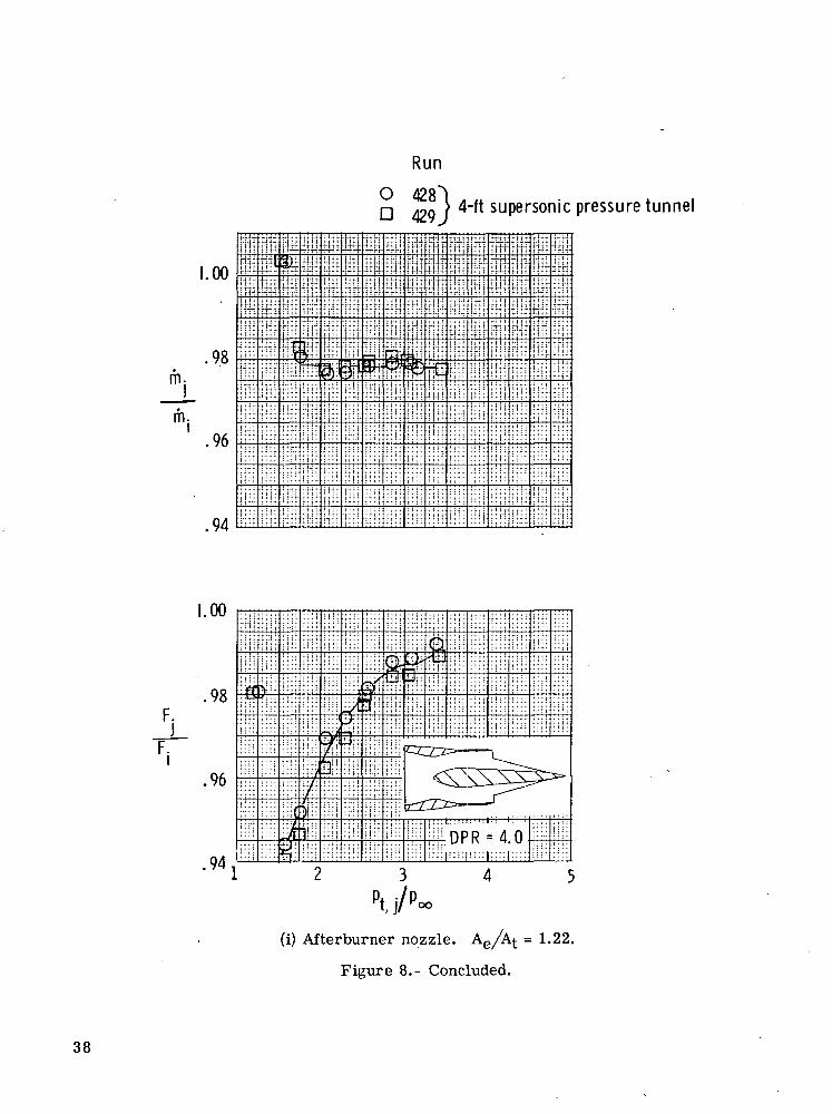
The static internal-performance characteristics of several two-dimensional wedgenozzle configurations are shown in figure 8. The parameters, the mass-flow ratio rhj /riijand the thrust ratio Fj/Fj are shown as a function of the jet total-pressure ratio Ptj/Poofor all configurations except the tertiary-air ejector configurations. At p. •/p = 2.5,
l,J/ 00
peak thrust ratios of about 0.968 and 0.985 were achieved for the unshrouded dry andunshrouded afterburner-power nozzles, respectively. Truncating the dry and afterburner-power nozzles reduced the peak thrust ratios to about 0.945 and 0.977 at p^. ./p = 2.5.The wedge truncation represented only 24 percent of the aft sloping wedge measured alongthe nozzle center line, but represented a base-area ratio A^/Am we(jge of 25 percent forthe .dry, and 43 percent of the afterburner-power nozzle. Similar reductions in the inter-nal performance were shown in reference 10 for a truncated, axisymmetric 15° cone plugnozzle with similar base to maximum plug-area ratios.
Generally, shrouding the wedge to achieve a higher internal area distribution causesa shift in the peak performance of the nozzle to higher jet total-pressure ratios consistent
10
with convergent-divergent nozzle design. However, as shown in figure 8(c) for the dry-power nozzle with an internal area ratio of 1.53 and a design pressure ratio of 6.50, a sig-nificant decrease in the internal performance is shown as the pressure ratio is increasedfrom about 5.0 to 6.0. This static-performance decrease is probably caused by shock-wave-induced separation on the wedge as a result of the shroud shock impingement on thewedge surface. If most of the wedge tip was separated, the performance of the shroudedwedge would be equivalent to the shrouded truncated wedge at the pressure ratio of 6.0.An inspection of figures 8(c) and 8(d) reveals that the performances are the same.
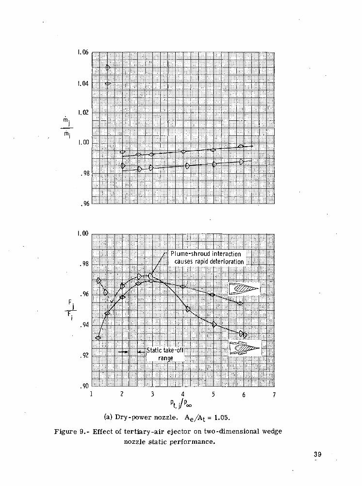
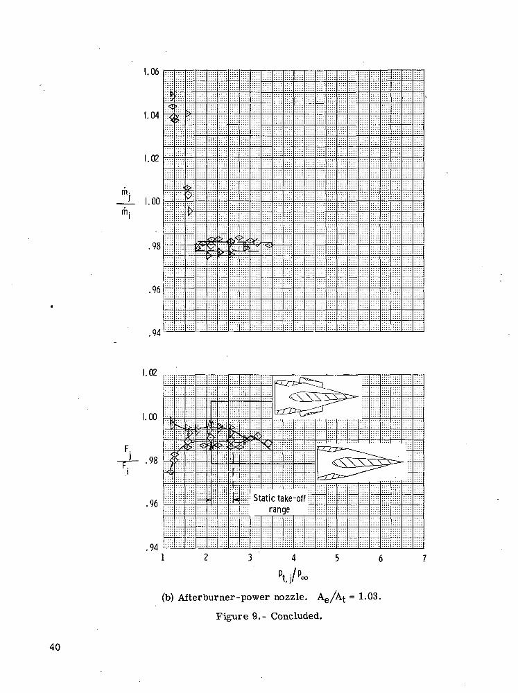
Figure 9 presents the effect of a tertiary-air ejector on two-dimensional wedge-nozzle static performance. Although the tertiary-air ejector design was not optimum,the data in figure 9 indicate that static internal-thrust performance can be increased upto a jet total-pressure ratio of about 3.0 for both the dry and the afterburner power noz-zles. This performance increase is significant because the ejector could also be used ina closed down position to form a shroud to obtain high internal area ratios for high per-formance at supersonic flight. Incorporating the tertiary-air ejector with this type oftwo-dimensional wedge nozzle also has attractive structural design features.
Aeropropulsion Performance
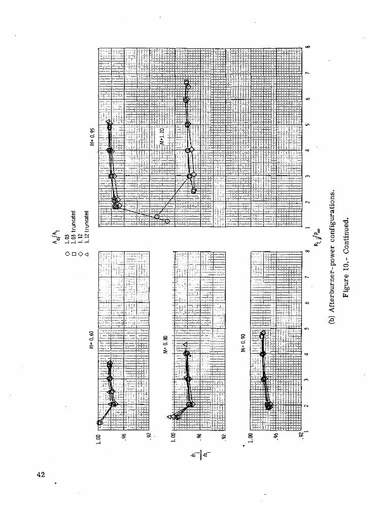
Figure 10 presents the variation of the mass-flow ratio with the jet total-pressureratio at several Mach numbers for the dry and afterburner-power nozzle configurations.Deviation in the mass-flow ratio was generally less than 1 percent for the dry-power con-figurations and less than 0.5 percent for the afterburner power configurations. Thesedeviations reflect the total accuracy of flow, area, and test condition measurement andshould affect thrust-ratio measurements negligibly.
Figures 11 and 12 present the variation of the thrust-minus-axial force ratio withthe jet total-pressure ratio at several Mach numbers for the dry and afterburner powernozzles, respectively. Internal-area ratios of 1.05 and 1.53 (shroud translated aft) weretested with and without a wedge truncation of 24 percent. The data in figure 11 indicatethat for all test Mach numbers the highest aeropropulsion performance was achieved withthe nontruncated baseline nozzle. As expected, the internal area ratio of 1.05 providedthe highest aeropropulsion performance up to a jet total-pressure ratio of about 4 at whichthe performance of the 1.53 internal area ratio became superior. The data in figure 11also indicate that the 24-percent wedge truncation has an adverse effect on the nozzle aero-propulsion performance with losses incurred of up to 4 percent of the ideal thrust. About2 percent of this loss is attributed to lower internal performance (see fig. 8), and theremainder is attributed to external flow effects.
The same cowl and translated-shroud length tested with the dry power wedge (seefig. 6) were tested with the afterburner wedge resulting in internal area ratios of 1.03
11

and 1.12. A longer shroud, resulting in an internal area ratio of 1.22, was tested at aMach number of 2.01. Only small changes in the internal area ratio were possible withshroud translation as a result of the low boattail angle of the afterburner power wedge.The data in figure 12 indicate very little change in the aeropropulsion performance withMach number for changes in the internal area ratio from 1.03 to 1.12 with the exceptionof M = 2.01. However, at the higher pressure ratios, slightly higher aeropropulsion per-formance was achieved for the 1.12 internal area ratio. This higher performance indi-cates that shroud translation could still be beneficial. The highest aeropropulsion gain(about 2.4 percent of Fj) using the translated shroud with Ae/Aj = 1.22 was noted atM = 2.01 as shown in figure 12(c). Also shown in figure 12(c) is a representative aero-propulsion performance value for a convergent-divergent nozzle with an area ratio of 1.6.Adverse effects from wedge truncation, although not as severe as with the dry powerwedge, still persist with the afterburner wedge.
External flow effects.- The external flow effects on the nozzle wedge and cowl axial-force ratio Fa^n/Fj are shown in figure 13 for the dry power nozzle and in figure 14 forthe afterburner power nozzle. It should be noted that the term Fa n contains cowl dragand wedge forces as noted in the section "Data Reduction." The data of figures 13 and 14show that increasing the jet total pressure decreases the cowl and wedge axial force(drag). Most of the drag reduction and/or the increased internal performance is probablythe result of favorable jet interference on the wedge boattail surface with the higher boat-tailed and larger projected-area, dry power wedge showing the greatest effect. The ben-eficial jet effect is also observed for the truncated-wedge configurations. However, at thejet pressure ratios below about 5, the truncated-wedge configurations exhibit higher dragforces and can be as much as 4 percent of the ideal thrust above the drag forces on thenontruncated-wedge configurations. An observation from these data is that at supersonicspeeds it is most important to have small external boattailing on the wedge centerbodyand to avoid any wedge truncation.
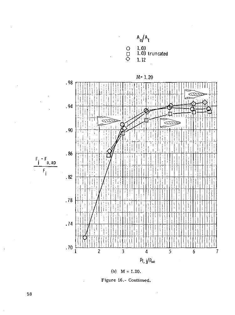
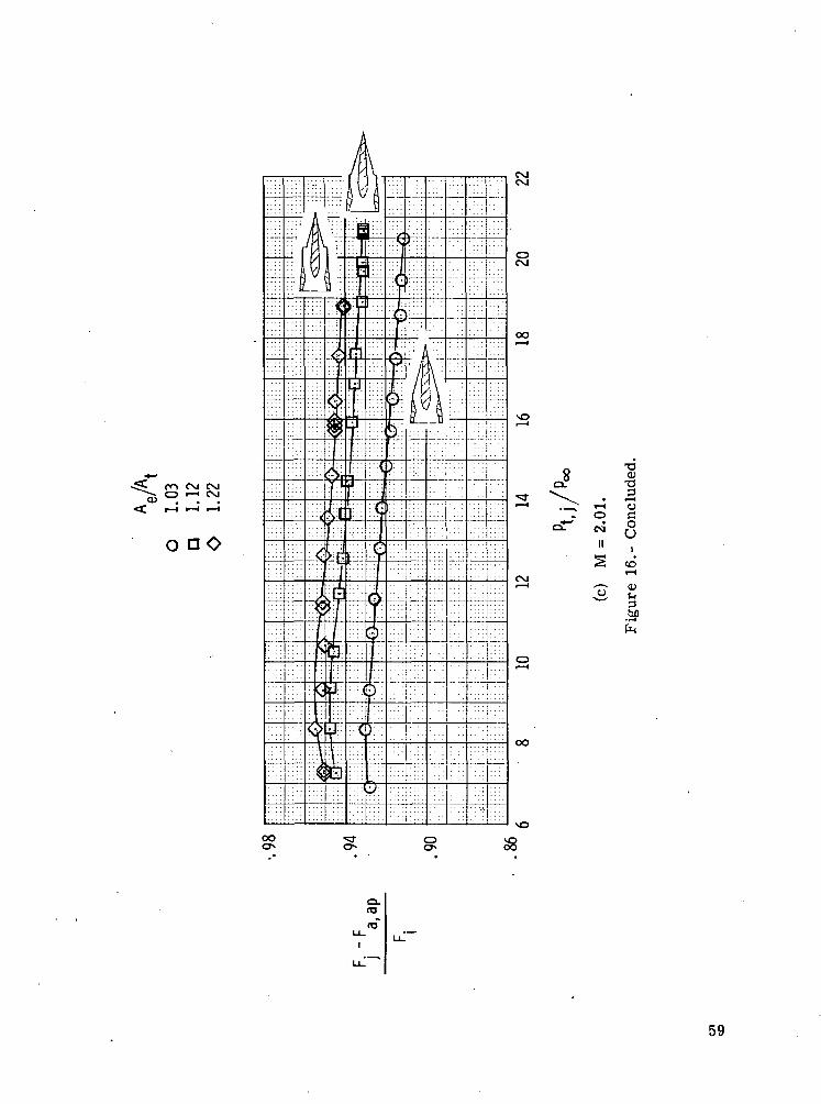
i ~ a apThe variation of the thrust-minus-axial pressure-force ratio ————'—- with theFijet total-pressure ratio for the dry and the afterburner-power nozzles at several Machnumbers is presented in figures 15 and 16, respectively. As discussed in the section
"Data Reduction," the term ] a,ap does not include the nozzle external-frictionFi
drag. The results of figures 15 and 16 are similar to those discussed for figures 11and 12, respectively, and are presented for reference.
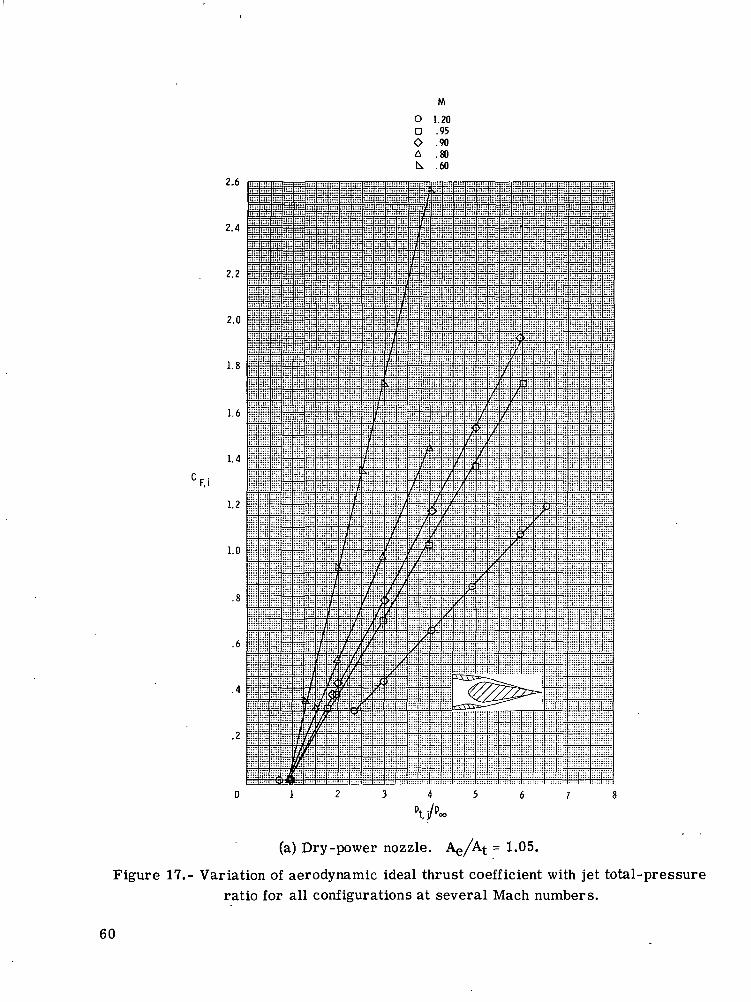
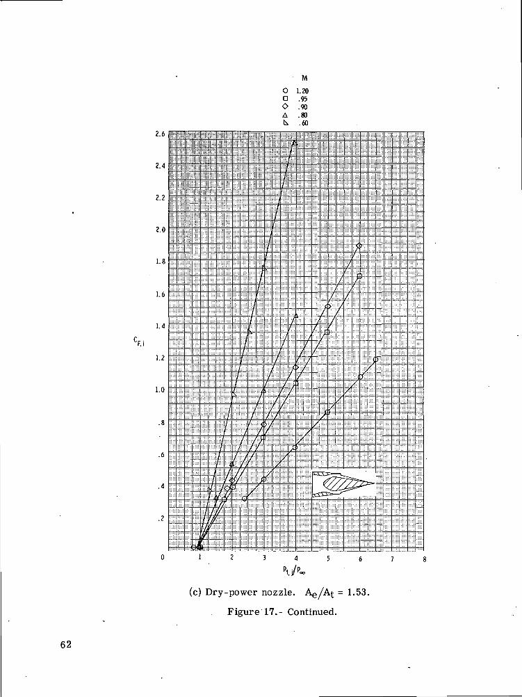
The variation of the aerodynamic ideal thrust coefficient with the jet total-pressureratio for all configurations is presented in figure 17 for all test Mach numbers. Thesedata are presented for reference only.
12

Figure 18 presents a schedule of the total-pressure ratio with the flight Mach num-ber for a typical low-bypass turbofan engine. Reference to these data is made in fig-ures 19 to 22.
Figure 19 presents the variation of the thrust-minus-drag ratio with Mach number.These data were obtained from the straight-line fairings of the basic data. Since the peak
p. _ Faeropropulsion performance — — for the dry power nozzle was attained at jet total-
Fjpressure ratios either lower with (Ag/Af. = 1.05) or higher (with Ae/At = 1.53J than theengine operating pressure-ratio schedule of figure 18, the aeropropulsion performancevalues shown in figure 19 are not optimized. The values can be improved by matchingthe internal area ratio of the nozzle to the design area ratios for the engine-operatingpressure-ratio schedule (EPR). For example, at M = 0.60 the EPR is about 3.4 whichrequires the internal area ratio to be about 1.14; at M = 0.90 the EPR is about 4.15which requires an internal area ratio of about 1.24. A maximum internal area ratio ofabout 1.3 appears to be sufficient for subsonic-transonic flight speeds. The data in fig-ure 19 indicate that, even in the off-design case, moderately high values of nozzle thrust-minus-axial force can be obtained with a horizontal wedge nozzle with a translating shroud.It can be noticed that as the Mach number and the engine pressure ratio increase, it isdesirable to increase Ae//Aj. by shroud translation. In actual operation, the nozzleshroud would be continuously variable from minimum to maximum Ae/A^, and thus per-formance could^be optimized at each flight condition. This performance can be approxi-mated by fairing a line through the maximum performance points of each Ae//A^ tested;these points are shown in figure 19. In addition, the data in figure 19 show that severeaeropropulsion losses can be-incurred with only a small truncation of the wedge.
Figure 20 presents the variation of the thrust-minus-axial pressure force with Machnumber at the scheduled pressure ratio. The results of this figure are similar to thethe results discussed for figure 19.
Convergent nozzle comparison.- Figure 21 presents the dry power, two-dimensionalwedge nozzle and the axisymmetric convergent nozzle performance (from ref. 9) for thejet total-pressure ratio schedule given in figure 18. The axisymmetric convergent nozzlewas chosen as a reference nozzle because of its predictable performance and because ithad been previously tested on the air-powered model used in this investigation. It shouldbe noted that these comparisons are not direct comparisons because of the differences in
/ Am ~ Aethe internal area ratio Ae/Aj. and the differences in the closure area ratio
between the convergent and the two-dimensional wedge nozzles. The effects of these dif-ferences are discussed in the following comparisons.
For static take-off, the most directly comparable condition, the convergent nozzleperformance is about 2 percent of the ideal thrust higher than that of the two-dimensional
13

wedge nozzle tested. The 2-percent loss in performance encountered with the two-dimensional wedge nozzle is attributed to friction losses on the large internal wettedarea, to a small loss of stagnation pressure at the throat caused by the intersectionof boundary layers in the corners of the nozzle throat, and to flow separation on the10° wedge boattail. The 2-percent performance loss can be reduced, as has been shownin figure 9, with the use of a tertiary-air ejector. An increase of about 1 percent of theideal thrust was achieved with a simple tertiary-air ejector. The ram drag on this typeof tertiary-air ejector would cancel the performance gain at or about M = 0.2. (Seeref. 11.) Therefore, a blow-in-door type of tertiary-air ejector may be a more prom-ising solution to the low two-dimensional wedge-nozzle static performance. The two-dimensional geometry minimizes the adverse effects on nozzle performance as wasencountered with earlier axisymmetric blow-in-door ejector installations with inter-fairings and horizontal-tail booms surrounding the nozzle. (See ref. 1.)
For subsonic speeds, the isolated dry power nozzle performance of the two-dimensional wedge nozzle tested is slightly inferior to the reference convergent nozzleup to approximately M = 0.85. Above this Mach number the transonic drag rise andincreased nozzle underexpansion losses of the convergent nozzle significantly lower itsperformance as is shown by the M = 0.90 data in figure 21. If the convergent nozzlegeometry were changed to convergent-divergent with Ae/At = 1.05 (equivalent to thebaseline two-dimensional nozzle geometry), the resulting axisymmetric C-D nozzle per-formance should be about 0.5 percent higher than the convergent-nozzle performanceshown at M = 0.90 for the scheduled pressure ratio. However, it should be noted that
"•TYI ~ Pthe closure area ratio — of the reference axisymmetric convergent nozzle isAmlower than that of the two-dimensional wedge nozzle. This condition means that the two-dimensional nozzle tested was charged with more closure area (boattailing) than the ref-erence convergent nozzle. If the closure area ratio of the axisymmetric convergent noz-zle were increased to that of the two-dimensional wedge nozzle, the performance shouldbe lower (estimated 0.5 percent of ideal thrust) than the convergent-nozzle performanceshown at M = 0.90 for the scheduled pressure ratio. These offsetting penalties indicatethat the comparisons at M = 0.90 in figure 21 are reasonable. These comparisons showthat the isolated aeropropulsion performance of the two-dimensional wedge nozzle is com-petitive with axisymmetric nozzles at transonic Mach numbers less than 1.0. Anotherinteresting observation is that, although the static (M = 0) performances of the baselinetwo-dimensional wedge with Ae//At = 1.05 or 1.53 are the same at a pressure ratioof 4.15 (as shown in fig. 8), the effect of the external flow (forward speed) is to increasethe aeropropulsion performance of the Ae/At = 1.53 nozzle (with translated shroud) asshown in figure 21 for M = 0.90 at the scheduled pressure ratio of 4.15. At M = 1.20the aeropropulsion value for the reference convergent nozzle was computed, subtracting
14

the theoretical flat-plate friction drag at M = 1.20 and the boattail pressure drag fromreference 9 from the theoretical internal performance of a convergent nozzle. The iso-lated nozzle aeropropulsion performance of the two-dimensional wedge nozzle withAe/At = 1.05 is shown in figure 21, at M = 1.20, to be slightly lower than the convergent-nozzle performance. A significant increase of 2.5 percent was achieved at M = 1.20 bytranslating the shroud to achieve Ae/At = 1.53 for the dry-power,.two-dimensionalwedge nozzle.
Figure 22 presents the afterburner-power, two-dimensional wedge nozzle, the axi-symmetric convergent nozzle (from ref. 12), and the convergent-divergent nozzle (fromref. 13) aeropropulsion performance at the scheduled jet total-pressure ratios. A similarargument as was discussed for figure 21 is made against direct comparisons with the dataof figure 22; however, the difference in the geometrical closure area ratios is less withthese axisymmetric nozzle comparisons.
For static acceleration take-off, the most directly comparable condition, the con-vergent nozzle performance is about 0.5 percent of the ideal thrust higher than that of thetwo-dimensional wedge nozzle tested. The 0.5-percent loss in performance encounteredwith the two-dimensional nozzle is attributed mainly to friction force on the large internalwetted area and to a small loss of stagnation pressure at the throat caused by the inter-section of boundary layers in the corners of the nozzle throat. As was shown for the dry-power nozzle, the static internal performance of the two-dimensional wedge nozzle wasincreased almost 1 percent of the ideal thrust with the use of a tertiary-air ejector.
At flight speeds the isolated nozzle afterburner-power performance of the two-dimensional wedge nozzle is slightly inferior to the convergent nozzle until a Mach num-ber slightly higher than 0.60 is attained. At transonic speeds the aeropropulsion perfor-mance of the two-dimensional wedge afterburner-power nozzle is superior to that of theconvergent nozzle. At M = 2.01, the aeropropulsion performance of a convergent-divergent nozzle with a 5° conical boattail and an Ae/At of approximately 1.6 was cal-culated using one-dimensional flow theory and boattail drag measurements from refer-ence 13. Because of the shallow boattail of the afterburner wedge, large values of theinternal area ratio cannot be achieved. However, with a moderately long shroud trans-lation an internal area ratio of 1.22 can be obtained. The data in figure 22 at M = 2.01indicate that high values of the aeropropulsion performance can be obtained with rela-tively low internal area ratios for a two-dimensional wedge nozzle. Hence it is concludedthat the two-dimensional wedge nozzle isolated performance can be competitive with theaxisymmetric convergent-divergent aeropropulsion performance at super sonic-flightMach numbers.
15

CONCLUSIONS
A wind-tunnel investigation has been conducted in the Langley 16-foot transonic and4-foot supersonic pressure tunnels on a two-dimensional variable-geometry wedge nozzlewith a collapsible wedge and a translating shroud. The investigation was conducted sta-tically and at flight speeds up to M = 2.01 at an angle of attack of 0°. The jet total-pressure ratio of the simulated exhaust was varied up to 21 depending on Mach number.
The results of the investigation indicate the following:
1. The aeropropulsion isolated performance of a variable-geometry two-dimensionalwedge nozzle is competitive with axisymmetric nozzles at transonic and supersonic Machnumbers.
2. For static take-off and low subsonic Mach numbers, the aeropropulsion perfor-mance of the variable-geometry two-dimensional wedge nozzle is slightly inferior (1 per-cent to 2 percent of ideal thrust) to a convergent nozzle. However, with the use of a sim-ple tertiary-air ejector, the static take-off performance of the two-dimensional wedgenozzle was increased about 1 percent of the ideal thrust in this investigation.
3. Truncation of the wedge centerbody to achieve a shorter nozzle can result insignificantly lower nozzle performance. A 24-percent wedge truncation of the baseline10° boattail wedge resulted in a 2-percent loss in the aeropropulsion performance atflight Mach numbers.
Langley Research Center,National Aeronautics and Space Administration,
Hampton, Va., February 12, 1975.
16

REFERENCES
1. Runckel, Jack F.: Interference Between Exhaust System and Afterbody of Twin-EngineFuselage Configurations. NASA TN D-7525, 1974.
2. Galigher, Lawrence L.: Performance of Various Twin-Nozzle Afterbody Configura-tions of an Air Superiority Fighter-Type Model at Mach Numbers From 0.6 to 2.5.AEDC-TR-72-17, U.S. Air Force, Feb. 1972.
3. Capone, Francis J.: Supercirculation Effects Induced by Vectoring a Partial-SpanRectangular Jet. AIAA Paper No. 74-971, Aug. 1974.
4. Corson, Blake W., Jr.; Runckel, Jack F.; and Igoe, William B.: Calibration of theLangley 16-Foot Transonic Tunnel With Test Section Air Removal. NASATR R-423, 1974.
5. Schaefer, William T., Jr.: Characteristics of Major Active Wind Tunnels at theLangley Research Center. NASA TM X-1130, 1965.
6. Goetz, G. F.; and Petit, J. E.: Integrated Nozzle Development Program, TransitionStudy Test Report. No. D180-15443 (Contract No. N00140-73-C0027), Boeing Co. .
7. Braslow, Albert L.; and Knox, Eugene C.: Simplified Method for Determination ofCritical Height of Distributed Roughness Particles for Boundary-Layer Transitionat Mach Numbers From 0 to 5. NACA TN 4363, 1958.
8. Braslow, Albert L.; Hicks, Raymond M.; and Harris, Roy V., Jr.: Use of Grit-TypeBoundary-Layer-Transition Trips on Wind-Tunnel Models. NASA TN D-3579,1966.
9. Reubush, David E.; and Runckel, Jack F.: Effect of Fineness Ratio on the BoattailDrag of Circular-Arc Afterbodies Having Closure Ratios of 0.50 With Jet Exhaustat Mach Numbers up to 1.30. NASA TN D-7192, 1973.
10. Berrier, Bobby L.: Effect of Plug and Shroud Geometry Variables on Plug-NozzlePerformance at Transonic Speeds. NASA TN D-5098, 1969.
11. Maiden, Donald L.; and Mercer, Charles E.: Performance Characteristics of a Single-Engine Fighter Model Fitted With an In-Flight Thrust Reverser. NASA TN D-6460,1971.
12. Reubush, David E.: Effects of Fineness and Closure Ratios on Boattail Drag ofCircular-Arc Afterbody Models With Jet Exhaust at Mach Numbers up to 1.30.NASA TN D-7163, 1973.
13. Compton, William B., Ill: Jet Effects on the Drag of Conical Afterbodies at SupersonicSpeeds. NASA TN D-6789, 1972.
17

mcCD
S•rH
•aio
73ced
o ..jS purt o
ofcCa>
soo
» .2S 1§ 8?S ^-b a>01 -H
S NN
S §
.2 iX bprt 73-1 Srt ?
cCD
OO
-I
18
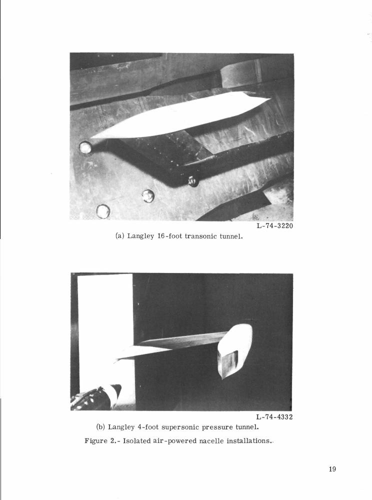
ov/ .L-74-3220
(a) Langley 16-foot transonic tunnel.
L-74-4332(b) Langley 4-foot supersonic pressure tunnel.
Figure 2.- Isolated air-powered nacelle installations.
19

10 oCO
20

L-74-3261(a) Three-quarter side view without shrouds.
L-74-3257(b) Three-quarter rear view.
Figure 4.- Nozzle component parts. Dry-power wedge installed.
21

o
1/1-oo>egooCroi_
-co.c00
o&_
^
o.c00
•a"
roQQ
_>,co
9ia>
roi_a>
CO0)
a>
22

-5o
•oCO
•co
ooCO
CO
23

15 c
1 '-i— fci
ra 5
1?°
ir\ & -
\\1
&
V11o
f(U
I
\. SL.
Ki/ // /
^~ §3 o
' c 75<c c
c
T3POf-i
CO
rti — iCOCa
rtCD
o>•I-*
S-iCD
O
COO)•c"rtfn0)
O>O
0)
i-H
Io
O
i— irtC.2COC0
o
.sCOa.
oo
0)ooo0)
r—4- N
SI
§
0)
-o0)
^CO
a>
24
IImm11
s
r0)
aoO)faD0> g
•l-t
"5oo
\0)
COc<D
a ?.I
O
«/)
c•5
o>-§>1a
X
i— <cs j<D_oor<"»oocx j^y f \ j CD r °o(\j r*^ ^T " U^ ^J *O CD OO f"— O* O>J
o •— CM CM m m *r ^r ^ o
r*^ f CD t*— r"H ^" f*1- ^"t ^" OO ^-< *oo* oo oo r— ^5 *& J£S ^3" <*^ c\J CNJ ro
0 ^^«^, «««,.. R
-o
? £CD J^
f §4^
rsi
X
»XJ CNJ u' WO C_> (-NJ r-"t 'J i \ iT» ^J 1—1
O i—t^Hi— i C \ J C \ J C N J C N J C \ J C S J C M i - H O
^g^-^^oo —Sr^or-^ScSu-NC\ jo^o^- t -<a-
1—1 CNJ r
25

noz, cm
140
130
120
110
100
90
80
70
60
50
40
304 6 8 10 12 14
x, cm (f rom circular cross section)
(c) Nozzle area distribution.
Figure 6.- Continued.
16 18
26

Circular cross-sectionstation-
Sta. 0
Sta. 0.693
Sta. 2.079
Wedge nose tangentstation—v
A X
Nozzle throatstation—^
Sta. 3.465 Sta. 6.930 Sta. 10.395 Sta. 13.860
Sta. 4.158 Sta. 7.623 Sta. 11.088
Sta. 5.544 Sta. 9.009 Sta. 12.474
•//////////
Sta. 2.772 Sta. 6.930 Sta. 9.702 Sta. 13.167
(d) Duct-wedge cross sections.
Figure 6.- Concluded.
r-Circular cross-sectionstation
Nozzle throat station
= 0°
Top view
27

Axisymmetric, circular-arc convergentnozzle from ref. 9 -J- r ^ 2 r
t
7.62 D
m-
_
.94
Run
O 429D 430O 445A 446
(a) 16-foot transonic-tunnel installation.
Figure 7.- Static performance of convergent nozzle used as calibration forair-powered nacelle. All dimensions are in centimeters.
28

— -7.62 Dt
1.02 ..............
m;
m;
F.JL
1.00
.98
.96
.94 L-
Ref. 9
roo
1 2 3
" Pt.i/P°
(b) 4-foot supersonic pressure tunnel installation.
Figure 7.- Concluded.
29

m.
m.
1.04
.02
.00
.98
.96
<v
•E
i
"*
i
K
i
i
r.~\
i
t ,
V
oD
-*
;f
i
3-
!
r***
'
— *-r-4
Run
494^1495 J
,
r .. i —
16-ft
'
MK==t
transonic tunnel
V-
i
-rfiu
, ii
j
i
F.
F.
1.00
.98
.96
.94
.92
.901
DPR =2.63
52 3 4
P t,j/Poo
(a) Dry-power nozzle. Ae/Aj = 1.05.
Figure 8.- Static performance characteristics of severaltwo-dimensional wedge configurations.
30

.02
.00m;
m;
.98
.96
RUn
O 409->D 410 >16-ft transonic tunnelO 411 J
1.00
.98
.96
F.
F.i .94
.92
.90
DPR -1.63I
3
Pt,j/P"
(b) Truncated wedge dry-power nozzle. Ae At = 1-05.
Figure 8.- Continued.
31

m.
mi
16 ft transonic tunnel
F.
F.
1.00
.98
.96
.94
.92
.90
.86
DPP =6.50
2 3 4 5
Pt.i/P~
(c) Dry-power nozzle. Ap/A^ = 1.53.
Figure 8.- Continued.
32

Run
i-ft transonic tunnel
1.00
.98
.96
.94
mm
92
.90
.86
.84
m;
m m m
m
fur
sir
IS a!
illi
IIHUBS
Ifu
iili
3*iTi-tt
ii
1
fen
li
II
1
milm
m
m m m
m m m mDPR =6.50
(d) Truncated dry-power nozzle. Ae/Aj; = 1.53.
Figure 8.- Continued.
33
Run
m.
m.
1.04
1.02
1.00
.98
lie
D 424 ) 16"fttransonic tunnel
A 415 ) 4"ft suPersonic Pressure tunnel
1.00
F.
77
1 2 3 4
PU/P~
(e) Afterburner power nozzle. At
Figure 8.- Continued.
= 1.03.
34
1.04
.02
m;L 1.00
m:
.98
.96
-fc
r
Run
O 425 "1D 426J
(r>-1
~
=i
t
3- H^
• "
.
16-ft transonic tunnel
F.
(f) Truncated afterburner-power nozzle. Ae/Af. » 1.03.
Figure 8.- Continued.
35

Run
m ;
m:
1.02
1.00
.98
.96
n 479~f16-fttransonictunnel
A 411 J 4"tt SLJPersonic Pressure tunnel
F.
77
1 2 3 4 5(g) Afterburner-power nozzle. Ae/A{ = 1.12.
Figure 8.- Continued.
36
Run
1.04
1.02
m.—L 1.00
m.
.98
16-ft transonic tunnel
1.00
.98
F. .96
F.
.94
.92
DPR =3.23
1 2 3 4(Ji) Truncated afterburner -power nozzle.
Figure 8.- Continued.
5= 1.12.
37
Run
O 428^1D 429 / ^ suPerson'c pressure tunnel
1.00
m.
F._J_F.
1.00
.98
.96
.94
7
-DPR = 4.0i i i i
5
(i) Afterburner nozzle. Ae/Aj- = 1.22.
Figure 8.- Concluded.
38
m ;
1.06
1.04
1.02
1.00
.98
.96
^
1.00
.98
.96
.94
.92
.90
Plume-shroud interactioncauses rapid deterioration
Static take-offfrange
1 2 3 4 5 6 7Pt,j/P~
(a) Dry-power nozzle. Ae//At = 1.05.
Figure 9.- Effect of tertiary-air ejector on two-dimensional wedgenozzle static performance.
39
.06
.04
1.02
m-_L 1.00rh;
.98
.96
.94
s.< >
.94 ^
Pt,j/P-
(b) Afterburner-power nozzle. Ae/A^ = 1.03.
Figure 9.- Concluded.
40

O> (U
"ro 15u oc c3 3
LT\
«
3J
i
-Hrh. . . i
-H-—: —
-•-!
rr.rt
~ HT — r-4
1 I
-~lrl— ini
§]
j
... .\
"-" E|
r+Ti-
l-rr—-. — '—
- ~. — _
-_ _.
r
[
\-"-~
V1 ""
w;
\\
. . . >
— . - )
" "1 "
^ — _1_
- • • '-
-— —!_
_J
^ZL
— : r-
:rtni
EE
-:::rr
>:::
!_l • •
•-7-; ;
-TTT-
J -i.
-B-rr; ; . i: . • i
ur-f-rr
! '
_J —— __iJU-zzrr
— i—3:0:;:
EEt
"EExE
EE
O D<><3
S
•S
:EJ_: L
~
:±ri
. :.:..
El
_ ;. -J
...<
;-l.E:VE-l
irr ^—
-ET::.._____.
-~n~F
_"::±;_
"i_iiiir
-L^q:
":'~
~:c"
- _ • _ :
L?.I
a~—
"Er
.EE.Jirr
;E£-rri-i-
-i-H--
ESE:_~4:_J-!-i-
EnZ:_;J!.|_,i-.
... . _L_
:-- '
j'EE
"Eri
EEE
E~
EE"EE-— -
~~ ;~
______
J — H-j_l_i_
lend::_•_
~.dr~
EE:
EEr
EGE
EE:1
E^E
EE:
EEE
EEIIT
8
§O
ca
o•iHH->rt?H
J>
'Sooo>
r—1NN
§!HCD£O
Q
<D
I
ort
rttnCD
£ca?H
om
.2^_>rtfn
a>^CQCQ0)
a>
-t_>•iH
?
.2-t-irt!H
&O
CQCQ
c.2-urt
• p-(!H
I
C31—f
0)
3bC
S
41
8 3
<: ^ -' ' •-'
O DO<
Si S
en
O•rH-*J
rt
IgO0f-i O<i> o
I •.S 20) O>C I*
t-,01
42

CQ CM CSJO ^H CVJ
o no
c\j
00
CVJ
•• oo
8
0)T3
O
U
CD733i-HO
OO
0)
.§>fe
00
43

0
8
CD
S
5 5 tru
ncat
ed3 3
trunc
ated
O n O<
So
S
£3
1
Oc
• 1 . 1
Or*
—ft
C
r^
st— i
N.
-o-
E "
hh—
'"v>>
-— s
cc
r
\_
-h-.. i.J.l !
DJ*
-v
-"N
s
^ —
A t
i
1 '^V^
3
C
I
ul""1
-^
-=r-
S
i i I r
"I
• • i t
*
^7-rj
..! !.. .
•H^^..-
f
1.1-L
.,! j !
. ! j-!-1 ' I
ar*
kr
u
1
3
rr
-1
i
i
H-
H-i-i —.i-i . '.
. • << < i
< \ •
1 ! . .
r .
-rr
•-«s=
i ;
i
r
*l
1
i
J-_L
4- 4_
I i < i i 1 • i
i ! i i
: ;
J — U '
i i-
M
T: • ; -t-1-
:.:.i i 4-
, - . ! _? ; ,
ulL-i- .4
— 1 i1 ' i f 1 | i
-4 II . UL-L . j , JJ
I
S
1 !
1 , |
J j
T — H-
— ; — t ,,;.._
44- -MM
! 1 • i
-J- -J-?- . !
44- -J_ J_ -
4-L -M j |
44- 4_U—
TT- ';-;-;•*•
-K-ht±rr^
*•
73
irv O
O
/T<
2 3
4
tota
l-p
ressu
re r
.
a m
0°.
o ^ ^— CO £ 0)
J °' ^ "1^ 73 0 §,sr s £ 5
- cd rto ^ -gco a> rt
w o ^
•rH >
^- y <uCT3 TO 03
2 3
on o
f th
rust-
min
unozz
le £
•E3
0 S-,
= rt>i•
T— 11— 1
CD«4
.1fe
44

O
m -o05 Q,
° |
rt oo U
oH
0)
45

F. -Fa,n
.94
.90
.86
.82
.78
O 1.05D 1.05 truncatedO 1.53
M- 1.20
.74
.70
.66
.62
.58
.54
.50
.46^-7 8
Pt,j/P«
(c) M=1.20.
Figure 11.- Concluded.
46
F. -Fa, n
Ae/At1.031.03 truncated1.121.12 truncated M=0.80
m I i
VFa.n
1.02
.98
.94
.90
.82
M-0.90
Q
M=0.95
(a) M = 0.60, 0.80, 0.90, and 0.95.
Figure 12.- Variation of thrust-minus-axial-force ratio with jet total-pressure ratiofor afterburner-power nozzle at several Mach numbers, a. = 0°.
47

F. -FJ a,n
F.
VAtO 1.03n 1.03 truncatedO 1.12
M- 1.20
(b) M = 1.20.
Figure 12.- Continued.
48

MMocQ
O
o>E
XCO
*^5* C**V CM CM f~^^> O *-H CM \0
oaoi
CMCM
aCM
oo
oo
T3CD
o c- 611 ,§ <N'
-
.§>
49
•ort
•\o05
oCO
oto
aS
'c?
O>oSHo
oo
"Hrt0)
IPO)
O)
SIO
Si0)
I
o0)
CD
O
CD
I
CO»-H
0)
50

CD
-oO>
sd13
LT\ LTV COCZ5 O LP>
ODO
C\J
oo
LTv
<M
T3
-S
Ou
— w
LTl CVJ
C.
to"
51

3 3
O O O < \-.-:-\ -:i:|--r!jz |jr~xnrz|
en*o
rt
o01
cuoomI-Hrt
oo73Crt<uhD
T3
<Di— tIS)(SI
§
a>
oCO
oCDO
II
? af-l3
^2t-,0)
-M
13coO0)
0)
0)-MX
W
•>-(CD
52
CD
s
•—^ CO CO CNJOJ O <O i—'
ODO
oCM
(XI
7373
O
OU
I
< 'i—i0)
53
•oo>
c
ir\ ir\o o
onoo
8 °CO
oT3CrtOto
.2rt
COCOo>
cu«r—»
£.PH
.2-Mrt
oHa
w
« §o G
5^ •*O O"Y rtg sr-< i-H
g g
s I& s
ra N
I §
CO
<D
a
S 3O "*H
!HOj
Q-l(O
*in
bC
54

ono<i
*o
.•<*-•ffi\j:
J--A
^
S
SE
te S?ft
ftn
in -COi O>
o g•o 3c crt oo OOS ,
2
§ S £8
55

Ae/At
O 1.05D 1.05 truncatedO 1.53
M-1.20
3 4
Pt,j/P«
(c) M = 1.20.
Figure 15.- Concluded.
56

a,ap
Ae/At
O 1.03D 1.03 truncatedO 1.12A 1.12 truncated
M-0.60 M-0.80
M-0.90 M-0.95
Pt,j/Poo
(a) M = 0.60, 0.80, 0.90, and 0.95.
Figure 16.- Variation of thrust-minus-axial pressure-force ratio with jet total-pressureratio for afterburner-power nozzle at several Mach numbers, a = 0°.
57
F. -FJ a,ap
F.
Ae/At
O 1.03D 1-03 truncatedO 1.12
1.20
,74
,70
(b) M = 1.20.
Figure 16.- Continued.
58
co CM
< _ _H -H
o no
T3
T3
i-H OO C^ o(M 0
" '.S CO
1—I
T? <"
bfl•i-H
h
o.
CT3
59
M
O 1.20D .95O .90A .80k .60
2.6
2.4
2.2
2.0
1.8
1.6
1.4
1.2
1.0
.6
mmBlaSiH8?8tEH in *|F t£[ :j:
^ISg35 Si Si s?
duw
<&&
if
33
'J.
t
l*-
JL
Jit-
W-
\/"-(a) Dry-power nozzle. Ag/A^ = 1.05.
Figure 17.- Variation of aerodynamic ideal thrust coefficient with jet total-pressureratio for all configurations at several Mach numbers.
60

CF,i
pt.j/p~(b) Truncated-wedge dry-power nozzle. Ae/Aj = 1.05.
Figure 17.- Continued.
61
M
2.6
1.0
.6
.4
(c) Dry-power nozzle. Ag/A^ = 1.53.
Figure 17.- Continued.
62

M
O 1.20a .95O .90A .80k .60
(d) Truncated-wedge dry-power nozzle. Ae/At = 1.53.
Figure 17.- Continued.
63

'F.i
5.2
(e) Afterburner-power nozzle. Ae/At =
Figure 17.- Continued.
1.03.
64

COo
CO
73
o -SrU fn'oT
65

CF,i
5.2
4.8
4.4
4.0
3.6
3.2
2.8
2.4
2.0
1.6
1.2
O 1.20D .95O .90A. .80k .60
.4
K2
tr
22^
• i!
Y
33 HE
siniiifsin
ffi
HeWl'
ill
sin
is
mm
i
1
Pi -/Di, ]/ roo
(f) Truncated-wedge afterburner-power nozzle. Ae/Aj. = 1.03.
Figure 17.- Continued.
66

CF,i
5.2
4.8
4.4
4.0
3.6
3.2
2.8
2.4
2.0
1.6
1.2
.8
.4
M
O 1.20D .95O .90A. .80N .60
11111
Si aft
U'f
1H-
tiiil
3S:
z
LJ.
T
(g) Afterburner power nozzle. Ae/Aj- = 1.12.
Figure 17.- Continued.
67
SBii
ocsi
I ' l i i l i i i l
7M
HTTP*
o>
ooU
T3
S
lt>t—l
o>
68

CF,i
3.6
3.2
2.8
2.4
2.0
1.6
1.2
.4
I
w.
7
3E22
2 ' 3
Pt.i/P°
(h) Truncated-wedge afterburner-power nozzle. Ae/A-t ~
Figure 17.- Continued.
69

\V
<=>cvi
cvicK
OO
Cvj
5Z-
\
H
O
CM"
\
\
ib
\i
f
in
X
ht it
cq
0>
^^ •
T3O>
Q) T3"3 £N "oo cs o
a
CD
70
\\\
\
\
ocsj
OO
00
csj
00
0)SiaJ2o
--
§
o• r-4-4->
rttn
0)
en0)
0)
0)
O)O
rt
rt««oOJ
I— I
•3CD
O
rto
• rHa
iod
• pH
Pn
71

A /A.el t
1.05 dry. 1.03 afterburner1.05 truncated dry, 1.03 truncated afterburner1.531.53 truncated1.12
- 1.12 truncated1.22 (M-2 only)
Dry-power nozzles'
Afterburner-power nozzles
Figure 19.- Variation of thrust-minus-axial-force ratio with Mach number at apressure ratio schedule for a high performance engine.
72

Ae/At
1.05 dry, 1.03 afterburner—— 1.05 truncated dry, 1.03 truncated afterburner
1.531.53 truncated1.121.12 truncated
Dry-power nozzles— 1.22 ( M - 2 only)
1.00Afterburner-power nozzles
2.0
Figure 20.- Variation of thrust-minus-axial pressure force with Mach number at apressure ratio for a high performance engine.
73

oCO.
S.I—
s.>^
oCM
LTl
O
oIa>
0)O
rtSt-,O
SISI
§•4J
o;bet.(D
Oo
SB •«S OjS -C
o>, w.2 oX x3rt rt
£0) 3
§0) O
.2.CQ
T3IO
<D
I
74

oaSfnO
S,SIN
§
01>oo
2 cu'S -3S -§
•r-l O
fS W
"S -rt gcu i
p—i CUN Ssi g2 wfi COo> y
I -a
waCDs
• rHT3I
O
f-,Q)
I
3J3f-,
eg
0)!H
NASA-Langley, 1975 L-9976 75

NATIONAL AERONAUTICS AND SPACE ADMINISTRATION
WASHINGTON. D.C. 2O546
OFFICIAL BUSINESS
PENALTY FOR PRIVATE USE S3OO SPECIAL FOURTH-CLASS RATEBOOK
POSTAGE AND FEES PAID
NATIONAL AERONAUTICS AND
SPACE ADMINISTRATION
451
UU7 001 C1 0 AL 750328 S00120ESPHILCO FORD CORPAERONUTRONIC DIVAEROSPACE & COMMUNICATIONS OPERATIONSATTN: TECHNICAL INFO SERVICESJAMBOREE & FORD ROADSNEWPORT BEACH CA 92663
POSTMASTER : If Undeliverable (Section 158Postal Manual) Do Not Return
"The aeronautical and space activities of the United States shall beconducted so as to contribute . . . to the expansion of human knowl-edge of. phenomena in the atmosphere and space. The Administrationshall provide for the widest practicable and appropriate disseminationof information concerning its activities and the results thereof."
—NATIONAL AERONAUTICS AND SPACE ACT OF 1958
NASA SCIENTIFIC AND TECHNICAL PUBLICATIONSTECHNICAL REPORTS: Scientific andtechnical information considered important,complete, and a lasting contribution to existingknowledge.
TECHNICAL NOTES: Information less broadin scope but nevertheless of importance as acontribution to existing knowledge.
TECHNICAL MEMORANDUMS:Information receiving limited distributionbecause of preliminary data, security classifica-tion, or other reasons. Also includes conferenceproceedings with either limited or unlimiteddistribution.
CONTRACTOR REPORTS: Scientific andtechnical information generated under a NASAcontract or grant and considered an importantcontribution to existing knowledge.
TECHNICAL TRANSLATIONS: Informationpublished in a foreign language consideredto merit NASA distribution in English.
SPECIAL PUBLICATIONS: Informationderived from or of value to NASA activities.Publications include final reports of majorprojects, monographs, data compilations,handbooks, sourcebooks, and specialbibliographies.
TECHNOLOGY UTILIZATIONPUBLICATIONS: Information on technologyused by NASA that may be of particularinterest in commercial and other non-aerospaceapplications. Publications include Tech Briefs,Technology Utilization Reports andTechnology Surveys.
Details on*fhe availability of these publications may be obtained from:
SCIENTIFIC AND TECHNICAL INFORMATION OFFICE
N A T I O N A L A E R O N A U T I C S A N D S P A C E A D M I N I S T R A T I O N
Washington, D.C. 20546