performance of elevated tanks in m 7.7 bhuj …home.iitk.ac.in/~dcrai/details/bhujeq.pdfperformance...
TRANSCRIPT
Performance of elevated tanks in Mw 7.7 Bhuj earthquakeof January 26th, 2001
Durgesh C Rai
Department of Civil Engineering, Indian Institute of Technology, Kanpur 208 016, India.
The current designs of supporting structures of elevated water tanks are extremely vulnerableunder lateral forces due to an earthquake and the Bhuj earthquake provided another illustrationwhen a great many water tank stagings suffered damage and a few collapsed. The more popularshaft type stagings suffer from poor ductility of thin shell sections besides low redundancy andtoughness whereas framed stagings consist of weak members and poor brace-column joints. Astrength analysis of a few damaged shaft type stagings clearly shows that all of them either met orexceeded the strength requirements of IS:1893–1984, however, they were all found deficient whencompared with requirements of the International Building Code. IS:1893–1984 is unjustifiably lowfor these systems which do not have the advantage of ductility and redundancy and are currentlybeing underestimated at least by a factor of 3 and need an upward revision of forces immediately.
1. Introduction
Many elevated water tanks suffered damage totheir staging (support structure) in the Mw 7.7Bhuj earthquake of January 26th, 2001 and atleast three of them collapsed. These water tanksare located in the area of a radius of approxi-mately 125 km from the epicenter (USGS). Themajority of these tanks are supported on cylin-drical shaft type staging which developed circum-ferential flexural cracks near the base. RC framedstagings are not very common for elevated tanksin this part of the country. Two of such tankslocated in regions of the highest intensity of shak-ing collapsed while a few developed cracking nearbrace-column joint regions. Critical facilities likewater tanks, therefore require careful scrutiny oftheir designs, especially those far away from theepicentral tract and located in the areas whichexperienced shaking of MSK intensity IX andVIII. Even in the regions of the highest shak-ing of intensity X, these structures should nothave collapsed. They are expected to remain func-tional even after the occurrence of a design levelearthquake.
2. Damage observed to elevatedwater tanks
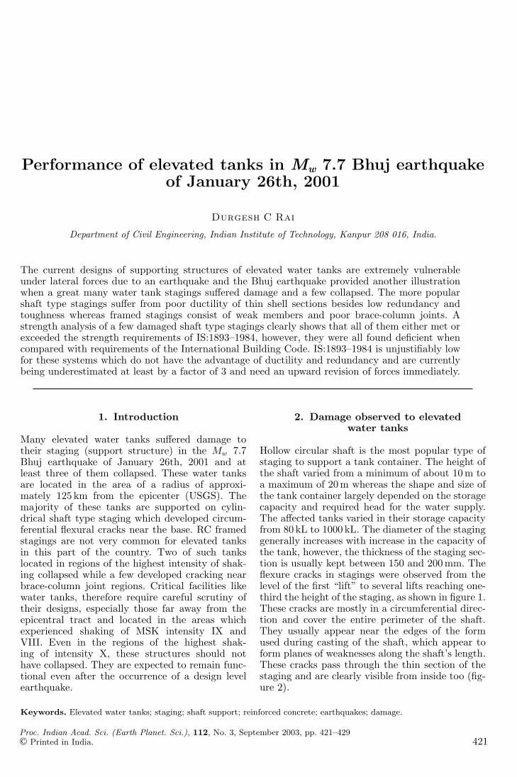
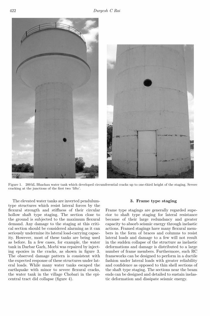
Hollow circular shaft is the most popular type ofstaging to support a tank container. The height ofthe shaft varied from a minimum of about 10 m toa maximum of 20 m whereas the shape and size ofthe tank container largely depended on the storagecapacity and required head for the water supply.The affected tanks varied in their storage capacityfrom 80 kL to 1000 kL. The diameter of the staginggenerally increases with increase in the capacity ofthe tank, however, the thickness of the staging sec-tion is usually kept between 150 and 200 mm. Theflexure cracks in stagings were observed from thelevel of the first “lift” to several lifts reaching one-third the height of the staging, as shown in figure 1.These cracks are mostly in a circumferential direc-tion and cover the entire perimeter of the shaft.They usually appear near the edges of the formused during casting of the shaft, which appear toform planes of weaknesses along the shaft’s length.These cracks pass through the thin section of thestaging and are clearly visible from inside too (fig-ure 2).
Keywords. Elevated water tanks; staging; shaft support; reinforced concrete; earthquakes; damage.
Proc. Indian Acad. Sci. (Earth Planet. Sci.), 112, No. 3, September 2003, pp. 421–429© Printed in India. 421
422 Durgesh C Rai
Figure 1. 200 kL Bhachau water tank which developed circumferential cracks up to one-third height of the staging. Severecracking at the junctions of the first two ‘lifts’.
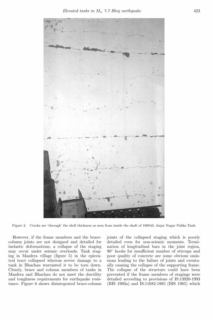
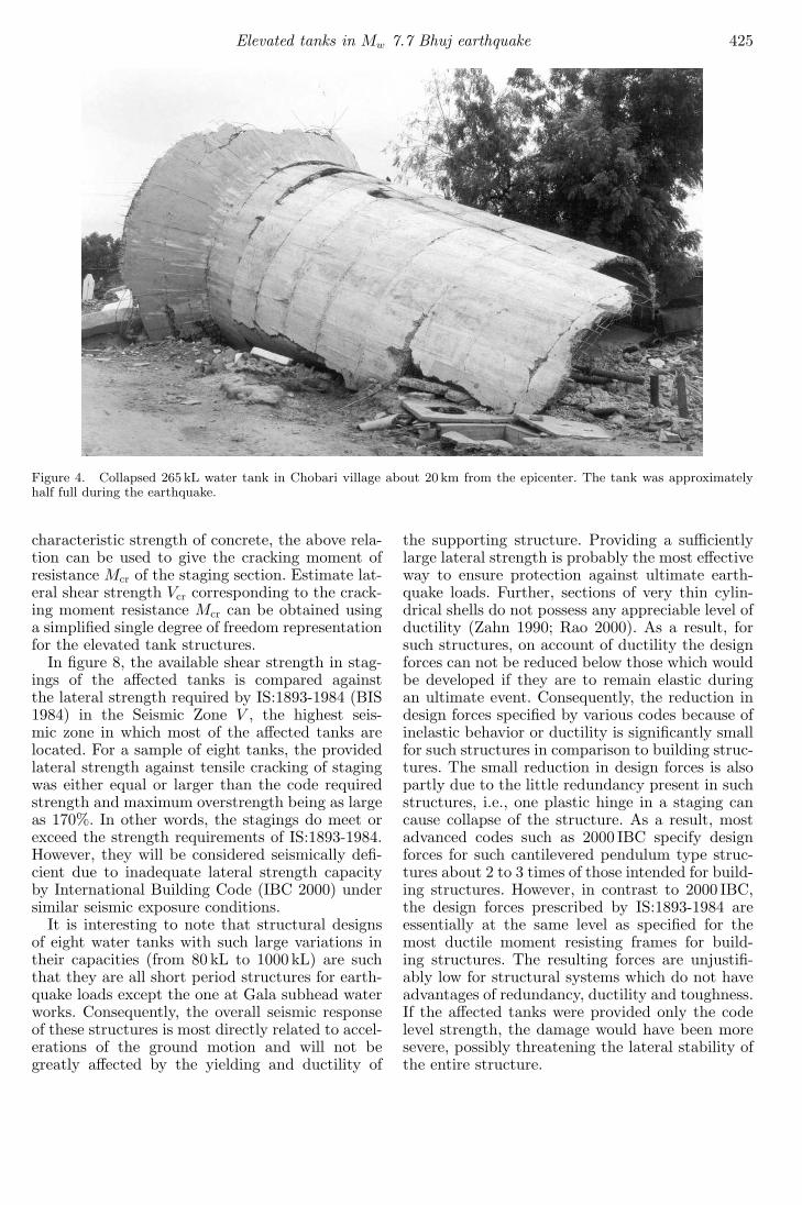
The elevated water tanks are inverted pendulum-type structures which resist lateral forces by theflexural strength and stiffness of their circularhollow shaft type staging. The section close tothe ground is subjected to the maximum flexuraldemand. Any damage to the staging at this criti-cal section should be considered alarming as it canseriously undermine its lateral load-carrying capac-ity. However, most of these tanks are being usedas before. In a few cases, for example, the watertank in Darbar Garh, Morbi was repaired by inject-ing epoxies in the cracks, as shown in figure 3.The observed damage pattern is consistent withthe expected response of these structures under lat-eral loads. While many water tanks escaped theearthquake with minor to severe flexural cracks,the water tank in the village Chobari in the epi-central tract did collapse (figure 4).
3. Frame type staging
Frame type stagings are generally regarded supe-rior to shaft type staging for lateral resistancebecause of their large redundancy and greatercapacity to absorb seismic energy through inelasticactions. Framed stagings have many flexural mem-bers in the form of braces and columns to resistlateral loads and damage to a few will not resultin the sudden collapse of the structure as inelasticdeformations and damage is distributed to a largenumber of frame members. Furthermore, such RCframeworks can be designed to perform in a ductilefashion under lateral loads with greater reliabilityand confidence as opposed to thin shell sections ofthe shaft type staging. The sections near the beamends can be designed and detailed to sustain inelas-tic deformation and dissipate seismic energy.
Elevated tanks in Mw 7.7 Bhuj earthquake 423
Figure 2. Cracks are ‘through’ the shell thickness as seen from inside the shaft of 1000 kL Anjar Nagar Palika Tank.
However, if the frame members and the brace-column joints are not designed and detailed forinelastic deformations, a collapse of the stagingmay occur under seismic overloads. Tank stag-ing in Manfera village (figure 5) in the epicen-tral tract collapsed whereas severe damage to atank in Bhachau warranted it to be torn down.Clearly, brace and column members of tanks inManfera and Bhachau do not meet the ductilityand toughness requirements for earthquake resis-tance. Figure 6 shows disintegrated brace-column
joints of the collapsed staging which is poorlydetailed even for non-seismic moments. Termi-nation of longitudinal bars in the joint region,90◦ hooks for insufficient number of stirrups andpoor quality of concrete are some obvious omis-sions leading to the failure of joints and eventu-ally causing the collapse of the supporting frame.The collapse of the structure could have beenprevented if the frame members of stagings weredetailed according to provisions of IS:13920-1993(BIS 1993a) and IS:11682-1985 (BIS 1985) which
424 Durgesh C Rai
Figure 3. Flexural cracks in staging of 500 kL tank being repaired by injecting epoxy. This tank in Morbi, 80 km awayfrom the epicenter, was empty at the time of the earthquake.
refers to the ductility requirements of IS:4326-1976(BIS 1976).
4. Lateral strength of shaft type stagingsand review of code seismic design forces
As shown in figure 7 due to lateral seismic forceson tank structures, the maximum moment occursat the base of the staging and for circular shafttype staging the points on the outer fibers of thestaging section are subjected to maximum bendingstress. The critical stress for design is obtained bycombining this maximum bending stress with theuniform axial compression stress due to the weight
of the tank structure. For the section to crack, it isnecessary that the combined stress at outer fibersexceeds the tensile strength of the concrete, fcr.Assuming thickness of staging t to be much smallerin comparison to the radius of staging r, and ignor-ing the small percentage of shell reinforcement, theexpression for the moment which will cause crack-ing, Mcr, can be obtained by equating combinedstress at outer fiber to the tensile strength of con-crete, i.e.,
− γP
2πrt+
Mcr
πr2t= fcr (1)
where, P is axial load and γ is the appropriateload factor. Taking fcr = 0.7
√fck MPa, where fck is
Elevated tanks in Mw 7.7 Bhuj earthquake 425
Figure 4. Collapsed 265 kL water tank in Chobari village about 20 km from the epicenter. The tank was approximatelyhalf full during the earthquake.
characteristic strength of concrete, the above rela-tion can be used to give the cracking moment ofresistance Mcr of the staging section. Estimate lat-eral shear strength Vcr corresponding to the crack-ing moment resistance Mcr can be obtained usinga simplified single degree of freedom representationfor the elevated tank structures.
In figure 8, the available shear strength in stag-ings of the affected tanks is compared againstthe lateral strength required by IS:1893-1984 (BIS1984) in the Seismic Zone V , the highest seis-mic zone in which most of the affected tanks arelocated. For a sample of eight tanks, the providedlateral strength against tensile cracking of stagingwas either equal or larger than the code requiredstrength and maximum overstrength being as largeas 170%. In other words, the stagings do meet orexceed the strength requirements of IS:1893-1984.However, they will be considered seismically defi-cient due to inadequate lateral strength capacityby International Building Code (IBC 2000) undersimilar seismic exposure conditions.
It is interesting to note that structural designsof eight water tanks with such large variations intheir capacities (from 80 kL to 1000 kL) are suchthat they are all short period structures for earth-quake loads except the one at Gala subhead waterworks. Consequently, the overall seismic responseof these structures is most directly related to accel-erations of the ground motion and will not begreatly affected by the yielding and ductility of
the supporting structure. Providing a sufficientlylarge lateral strength is probably the most effectiveway to ensure protection against ultimate earth-quake loads. Further, sections of very thin cylin-drical shells do not possess any appreciable level ofductility (Zahn 1990; Rao 2000). As a result, forsuch structures, on account of ductility the designforces can not be reduced below those which wouldbe developed if they are to remain elastic duringan ultimate event. Consequently, the reduction indesign forces specified by various codes because ofinelastic behavior or ductility is significantly smallfor such structures in comparison to building struc-tures. The small reduction in design forces is alsopartly due to the little redundancy present in suchstructures, i.e., one plastic hinge in a staging cancause collapse of the structure. As a result, mostadvanced codes such as 2000 IBC specify designforces for such cantilevered pendulum type struc-tures about 2 to 3 times of those intended for build-ing structures. However, in contrast to 2000 IBC,the design forces prescribed by IS:1893-1984 areessentially at the same level as specified for themost ductile moment resisting frames for build-ing structures. The resulting forces are unjustifi-ably low for structural systems which do not haveadvantages of redundancy, ductility and toughness.If the affected tanks were provided only the codelevel strength, the damage would have been moresevere, possibly threatening the lateral stability ofthe entire structure.

426 Durgesh C Rai
Fig
ure
5.(a
)C
olla
psed
slen
der
and
wea
kfr
amed
stag
ings
ofw
ater
tank
sin
Man
fera
villa
ge.(b
)Se
vere
dam
age
tosi
mila
rst
agin
gre
quir
edth
atth
ew
ater
tank
bepu
lled
dow
nin
Bha
chau
.

Elevated tanks in Mw 7.7 Bhuj earthquake 427
Figure 6. Poor detailing of column-brace joints for Manferatank.
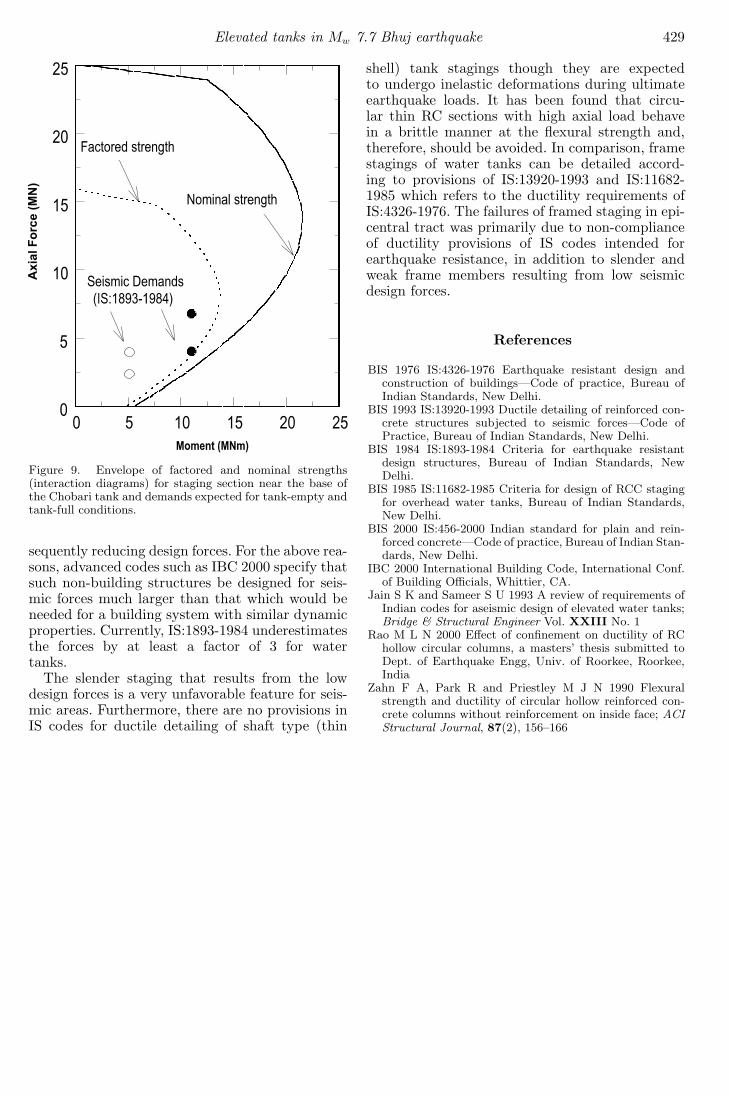
An ultimate strength analysis of the stagingsection of the collapsed Chobari water tank iscarried out which involved the calculation of ulti-mate direct force and ultimate bending momentthat can be resisted by the resulting stress enve-lope. The envelope of resistance is presented inthe form of an interaction plot with the momentas the abscissa and axial load as the ordinate.The strength interaction curves were developedcorresponding to factored strengths and nominalstrengths as per IS:456–2000 (BIS 2000). Geomet-rical and material parameters used to derive theresistance envelope were:• Mean radius of section r = 2.25 m,• Shell thickness t = 160 mm,• Ratio of longitudinal steel to gross section =
0.00283,• Angle subtended by door opening at the center
of the section = 0.44 rad,
• Cube strength of concrete fck = 20 MPa, and• Yield strength of reinforcement fy = 415 MPa.
To assess the safety of the structure, the avail-able capacity at the critical section is comparedwith probable demands specified by IS:1893-1984.The ‘open’ and ‘filled’ circles in figure 9, repre-sent factored seismic demand for empty and fulltank cases according to the two critical load com-binations. It is clear that the staging of Chobariwater tank was probably safe for seismic forcesspecified by IS:1893-1984, if we ignore the possibil-ity of poor quality construction which can not beruled out considering its remote location. In otherwords, the seismic forces were indeed larger thancode specified forces on the morning of the earth-quake when the tank was about half full. A lowseismic design force results in low flexural demandfrom the staging section which encourages slenderstagings with thin shell sections. It is clear thatdamages observed in stagings of elevated watertanks once again illustrate that the IS:1893-1984design forces are currently being underestimatedby at least a factor of 3 and need an upwardrevision of forces immediately. In an earlier studyJain and Sameer (1993) have also pointed out thisdeficiency of IS:1893-1984 and advocated that theforces be increased by increasing the performancefactor for elevated water tanks to 3 from the cur-rent value of 1.
5. Conclusions
The current designs of RC shaft type circular stag-ing (supporting structure) for elevated water tanksare extremely vulnerable to lateral loads caused byearthquakes. It is evident from the damages sus-tained to stagings as far as 125 km away from theepicentral tract of the Bhuj earthquake. This isdespite the fact that most stagings could withstandthe seismic forces greater than those specified byIS:1893-1984.
The supporting structure, especially the framedstagings may look like that used in the building-likestructures but its behaviour under seismic loadsis very different. Moreover, the staging does nothave much redundancy and hence toughness – adesirable feature for earthquake-resistance – whichis typically present in the multiple bays and frame-lines of a building framing system. This lack ofredundancy is extremely serious in circular shafttype staging where lateral stability of the struc-ture depends on only a single element, i.e., shaft,and failure of which would severely jeopardize thelateral stability of the entire structure. Also thinsections of shaft type staging do not have anappreciable level of ductility which can be takenadvantage of in dissipating seismic energy and con-

428 Durgesh C Rai
Figure 7. Stresses developed in shell staging.
Figure 8. Comparison of available shear strength against tensile cracking of eight tanks with base shear strengths requiredby IS:1893-1984 and IBC 2000 codes, respectively. Open circles represent tank-empty condition while full circles representtank-full condition.
Elevated tanks in Mw 7.7 Bhuj earthquake 429
Figure 9. Envelope of factored and nominal strengths(interaction diagrams) for staging section near the base ofthe Chobari tank and demands expected for tank-empty andtank-full conditions.
sequently reducing design forces. For the above rea-sons, advanced codes such as IBC 2000 specify thatsuch non-building structures be designed for seis-mic forces much larger than that which would beneeded for a building system with similar dynamicproperties. Currently, IS:1893-1984 underestimatesthe forces by at least a factor of 3 for watertanks.
The slender staging that results from the lowdesign forces is a very unfavorable feature for seis-mic areas. Furthermore, there are no provisions inIS codes for ductile detailing of shaft type (thin
shell) tank stagings though they are expectedto undergo inelastic deformations during ultimateearthquake loads. It has been found that circu-lar thin RC sections with high axial load behavein a brittle manner at the flexural strength and,therefore, should be avoided. In comparison, framestagings of water tanks can be detailed accord-ing to provisions of IS:13920-1993 and IS:11682-1985 which refers to the ductility requirements ofIS:4326-1976. The failures of framed staging in epi-central tract was primarily due to non-complianceof ductility provisions of IS codes intended forearthquake resistance, in addition to slender andweak frame members resulting from low seismicdesign forces.
References
BIS 1976 IS:4326-1976 Earthquake resistant design andconstruction of buildings—Code of practice, Bureau ofIndian Standards, New Delhi.
BIS 1993 IS:13920-1993 Ductile detailing of reinforced con-crete structures subjected to seismic forces—Code ofPractice, Bureau of Indian Standards, New Delhi.
BIS 1984 IS:1893-1984 Criteria for earthquake resistantdesign structures, Bureau of Indian Standards, NewDelhi.
BIS 1985 IS:11682-1985 Criteria for design of RCC stagingfor overhead water tanks, Bureau of Indian Standards,New Delhi.
BIS 2000 IS:456-2000 Indian standard for plain and rein-forced concrete—Code of practice, Bureau of Indian Stan-dards, New Delhi.
IBC 2000 International Building Code, International Conf.of Building Officials, Whittier, CA.
Jain S K and Sameer S U 1993 A review of requirements ofIndian codes for aseismic design of elevated water tanks;Bridge & Structural Engineer Vol. XXIII No. 1
Rao M L N 2000 Effect of confinement on ductility of RChollow circular columns, a masters’ thesis submitted toDept. of Earthquake Engg, Univ. of Roorkee, Roorkee,India
Zahn F A, Park R and Priestley M J N 1990 Flexuralstrength and ductility of circular hollow reinforced con-crete columns without reinforcement on inside face; ACIStructural Journal, 87(2), 156–166