performance of rigid welded beam to column …
TRANSCRIPT

1601
1 Manager, HERA Steel Structures Analysis Service2 Structural Engineer, HERA3 Department of Civil and Resource Engineering, University of Auckland4 Manager, New Zealand Welding Centre and HERA Deputy Director
PERFORMANCE OF RIGID WELDED BEAM TO COLUMN CONNECTIONSUNDER SEVERE SEISMIC CONDITIONS
Clark W K HYLAND1, Charles G CLIFTON2, John W BUTTERWORTH3 And Wolfgang SCHOLZ4
SUMMARY
This paper presents details of the current design model used for rigid welded beam to columnconnections in New Zealand moment-resisting steel framed (MRSF) seismic-resisting systems.This design model was revised following the January 1994 Northridge earthquake, in light of thedamage to the standard US rigid welded MRSF connection in that severe event.
The efficacy of the model was tested in two series of tests; the first under pseudo-static rates ofloading and the second at seismic-dynamic rates of loading. A brief overview of the scope, aimand key results from these tests is given. The paper concludes with references to sources of moredetailed information on the design model and test series.
INTRODUCTION
Background
During the 1994 Northridge (Los Angeles) earthquake, many large-scale welded beam to column connections inmoment-resisting steel frames performed poorly, undergoing connection failure prior to development of theexpected inelastic action in the beams. The predominant failure mode involved sudden fracture of the beamflange to column flange connection, turning the as-designed rigid joints into actual semi-rigid joints.
Although the pre-1994 site-welded, shop-bolted detail used in Los Angeles is seldom used in New Zealand, theexercise of reasonable prudence led to the New Zealand rigid welded connection design model being reassessed.A revised design model for this type of joint was subsequently put through two sets of experimental tests; alarge-scale, pseudo-static test series on seven specimens [Butterworth, 1997] and a large-scale, seismic-dynamictest series on five specimens [Scholz et.al., 1997]. (The latter tests were undertaken at earthquake rates ofloading, the former tests at 10-2 to 10-3 times earthquake rates of loading).
These tests demonstrated the validity of the revised design model and the provisions incorporated into the 1997revision of the Steel Structures Standard [NZS 3404, 1997].
Scope of Paper
First, this paper presents the general philosophy behind the seismic design of connections in New Zealand.
It then presents, in as much detail as space permits, the New Zealand design model for rigid welded connections.This is followed by brief details of the two experimental testing programmes used to verify important aspects ofthis design model. The paper concludes with comments on the validity of the design model and key results fromthe research programme. This is followed by the references, tables and figures.

16012
PHILOSOPHY BEHIND THE SEISMIC DESIGN OF CONNECTIONS
The general philosophy behind the seismic design of connections, as summarised from [Clifton, 1999], are asfollows:
(1) Select a load path through the connection that is as simple and direct as practicable. In making thisselection:
(1.1) Determine realistically the internal actions being generated in the members being connected, when thesemembers are responding inelastically. For example, in an I-section subject to inelastic bending, theflange and at least half the web will develop in excess of their horizontal yield capacity.
(1.2) Determine actions on members based on the anticipated inelastic response of the overall structuralsystem. This is especially applicable to determining column axial loads in seismic-resisting systems.
(1.3) Make provisions for transfer of internal forces from elements of the supported member into elements ofthe supporting member that lie parallel to the incoming force. For example, in a rigid beam to columnstrong axis connection, the incoming beam flange axial force must pass through the column flange andinto the column web.
(1.4) Make provision for component forces introduced when an applied force changes direction.(1.5) Design to suppress connector-only failure modes (ie. bolt or weld failure alone) by making the design
capacity of connectors sufficiently greater than either the design capacity of connection components orthe design capacity of combined connector/connection component modes of failure.
(1.6) Ensure that all load paths from a supported member element to a supporting member element areeffectively equally stiff, unless the effect of differential movement within the connection is known to benot detrimental. This means, for example, that if the flanges of a beam are directly welded to a column,the beam web must also be directly welded to that column and not connected via a welded or boltedcleat. Similarly, all elements of a beam must be directly welded to the endplate in a moment-resistingendplate connection and the endplate is then bolted to the column.
(1.7) Welds transferring force between two elements that are perpendicular (eg. from a beam flange into acolumn flange) must allow for a balanced, symmetrical transfer of force. This means either double-sided fillet welds of equal leg length, double-sided incomplete penetration butt welds of equal size orcomplete penetration butt welds.
(2) Design all connection components and connectors to resist the design actions associated with the givenload path, including overstrength actions where required (NZS 3404 provides appropriate guidance).
(3) Avoid, wherever possible, weld details where the skill of the welder determines the strength andperformance of the weldment. Where this cannot be avoided, pay particular attention to meeting thespecified weld quality for these welds.
(4) Avoid putting welds into direct bending.(5) Detail the connection to retain its dependable load-carrying capacity under anticipated inelastic rotation
of the connected members. Specific instances of this are given in NZS 3404.(6) Ensure that weld consumables, bolts and steel are suitably notch-tough (NZS 3404 gives suitable
guidance regarding material selection).
DESIGN MODEL FOR RIGID WELDED CONNECTIONS
Scope of Coverage
Design model details presented herein relate to the connection between the beam and the column in aconventional, rigid, shop-welded connection.
Design aspects relating to the connection interface between the beam member and the column face are presentedin detail, while design of the column stiffeners and panel zone are covered in general philosophy terms only,with reference to the relevant provisions of NZS 3404.
Welds Between Beam Flanges and Column Flange
The location of these welds is shown in Figure 1. They are required to transmit the tension capacity of the flangeinto the column. The specific requirements, from Clause 12.9.1.2.2(1) of NZS 3404, are as follows:

16013
(1) For complete penetration butt welds, the weld must be stronger than the beam flange, in accordancewith AS 2205.2.1. Also, for welds connecting members that will be subject to inelastic demand underseismic action, uuw ff ≥ is required, where uwf is the nominal tensile strength of the weld metal and ufis the nominal tensile strength of the parent metal.
(2) For double-sided fillet welds, the required beam flange design action, ∗fS , is given by:
ybffomsuomsf ftbRS φ=φ=∗(1)
where:
omsφ = overstrength factor from Table 12.2.8(1) of NZS 3404 [5]
ybff u ftbR = = nominal yielding capacity of full flange section ( fb = flange width; ft = flange
thickness); ybf = nominal yield stress)
The overstrength action in equation 1 reflects the fact that the beam flange to column flange weld is the primaryload-carrying path from the beam to the column and that the nominal capacity of the flange will be exceeded, inpractice, due to material variation and strain hardening. Both these factors are accounted for in the overstrengthfactor.
The fillet weld design capacity, wVφ , to resist ∗fS , is determined from Clause 9.7.3.10 of NZS 3404 by:
wVφ = wtuw Ltf6.0φ (2)
where:
φ = strength reduction factor = 0.8 for fillet weld category SP, which is the weld category required by[NZS 3404] for seismic applications
tt = design throat thickness = 2/wt for an equal leg length fillet weld
wt = leg length of fillet weld
wL = length of weld = wbbf2 t−
fb = width of the beam flange
wbt = thickness of the beam web
Equation 2 is based on the principle that the nominal capacity of the weld is given by shear failure (at uw6.0 f )
across a failure plane of the weld defined by ( wtLt ).
Welds Between Beam Web and Column Flange
The location of this weld is shown in Figure 1. A beam web undergoing yielding due to inelastic moment oraxial tension will develop longitudinal action equal to the tension yield capacity of the web, at least over theregion of the web adjacent to the beam tension flange. For dependable joint performance, the beam web tocolumn flange weld must be able to transfer this action directly through to the column flange, via a load path ofcomparable stiffness to that through the beam flange into the column flange.
This weld is typically a double-sided fillet weld and the above requirements lead to a weld design action, ∗ws ,
given by equation 3 from [Feeney and Clifton, 1995].
∗ws = ywwb5.0 ftφ (3)
where:
∗ws = design action/unit length on each weld of the double-sided fillet weld

16014
wbt = thickness of the beam web
ywf = yield stress of the beam web
φ = 0.9 (φ for the beam web, as given by [NZS 3404] for a butt weld of SP category)
For beams in inelastic bending under seismic action, sizing the weld on this basis over the full depth of the webwill provide adequate capacity to resist the associated vertical shear force [Feeney and Clifton, 1995].
The fillet weld design capacity/unit length is again determined, from Clause 9.7.3.10 of [NZS 3404], by:
wvφ = tuw6.0 tfφ (4)
Transfer of Internal Actions from the Beam into the Column
This requirement is made to suppress net section fracture at the interface between the beam flange weld and thecolumn flange (along the line AA in Figure 1). The need for this comes from a review of the USA joint failuresin the Northridge, 1994 earthquake and the application of this to New Zealand connections [Clifton et.al, 1998].The requirement is expressed as equation (5):
ηφφ
≥tc
yboms
fb f
f
A
A
u
fct
9.0(5)
where:
fctA = area, in elevation, of the column flange over which the incoming beam tension flange force
( ∗fbtN in Figure 1) is transmitted into the column flange.
fbA = area of the beam (tension) flange
ybf = nominal yield stress of the beam flange
ucf = nominal tensile strength of the column (flange)
tφ = through thickness to longitudinal tensile strength factor = 1.0 for steels of Australasian origin and
0.85 for hot-rolled wide flange jumbo column sections >40mm thickη = column flange force reduction factor, which = 1.0 except for high values of (axial load &
moment), as given by [Clifton et.al., 1998; Feeney & Clifton, 1995].
Details regarding the use of equations 5 and 6 are given in section 8.1.2 of [Feeney & Clifton, 1995], includingthe use of fillet weld reinforcing of a complete penetration butt weld, if equation 5 is slightly undermet.
Use of double-sided fillet welds between the beam flanges and the column flange, rather than a completepenetration butt weld, is advantageous in meeting equation 5, as fctA is more than doubled.
Column Stiffeners and Panel Zone
The design requirements for these are presented in Clause 12.9.5 of NZS 3404.
The tension and compression stiffeners are designed to transmit the internal axial forces from overstrength beamflange action (tension/compression), into the column, via the flanges and web. These stiffeners are sized for theoverstrength action, so that inelastic action in them is minimised.
The panel zone design is based on preventing significant inelastic action developing in this region until theincoming beam(s) have commenced to yield, then allowing panel zone yielding to develop as an additionalmeans of absorbing the overstrength beam actions.
EXPERIMENTAL TESTING PROGRAMMES
16015
Aim and Scope of Test Programmes
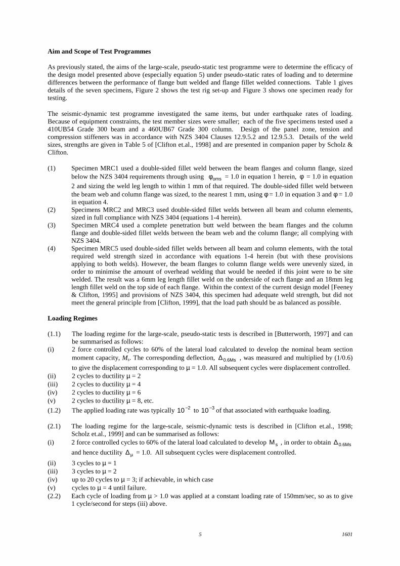
As previously stated, the aims of the large-scale, pseudo-static test programme were to determine the efficacy ofthe design model presented above (especially equation 5) under pseudo-static rates of loading and to determinedifferences between the performance of flange butt welded and flange fillet welded connections. Table 1 givesdetails of the seven specimens, Figure 2 shows the test rig set-up and Figure 3 shows one specimen ready fortesting.
The seismic-dynamic test programme investigated the same items, but under earthquake rates of loading.Because of equipment constraints, the test member sizes were smaller; each of the five specimens tested used a410UB54 Grade 300 beam and a 460UB67 Grade 300 column. Design of the panel zone, tension andcompression stiffeners was in accordance with NZS 3404 Clauses 12.9.5.2 and 12.9.5.3. Details of the weldsizes, strengths are given in Table 5 of [Clifton et.al., 1998] and are presented in companion paper by Scholz &Clifton.
(1) Specimen MRC1 used a double-sided fillet weld between the beam flanges and column flange, sizedbelow the NZS 3404 requirements through using omsφ = 1.0 in equation 1 herein, φ = 1.0 in equation
2 and sizing the weld leg length to within 1 mm of that required. The double-sided fillet weld betweenthe beam web and column flange was sized, to the nearest 1 mm, using φ = 1.0 in equation 3 and φ = 1.0in equation 4.
(2) Specimens MRC2 and MRC3 used double-sided fillet welds between all beam and column elements,sized in full compliance with NZS 3404 (equations 1-4 herein).
(3) Specimen MRC4 used a complete penetration butt weld between the beam flanges and the columnflange and double-sided fillet welds between the beam web and the column flange; all complying withNZS 3404.
(4) Specimen MRC5 used double-sided fillet welds between all beam and column elements, with the totalrequired weld strength sized in accordance with equations 1-4 herein (but with these provisionsapplying to both welds). However, the beam flanges to column flange welds were unevenly sized, inorder to minimise the amount of overhead welding that would be needed if this joint were to be sitewelded. The result was a 6mm leg length fillet weld on the underside of each flange and an 18mm leglength fillet weld on the top side of each flange. Within the context of the current design model [Feeney& Clifton, 1995] and provisions of NZS 3404, this specimen had adequate weld strength, but did notmeet the general principle from [Clifton, 1999], that the load path should be as balanced as possible.
Loading Regimes
(1.1) The loading regime for the large-scale, pseudo-static tests is described in [Butterworth, 1997] and canbe summarised as follows:
(i) 2 force controlled cycles to 60% of the lateral load calculated to develop the nominal beam sectionmoment capacity, Ms. The corresponding deflection, 0.6Ms∆ , was measured and multiplied by (1/0.6)
to give the displacement corresponding to µ = 1.0. All subsequent cycles were displacement controlled.(ii) 2 cycles to ductility µ = 2(iii) 2 cycles to ductility µ = 4(iv) 2 cycles to ductility µ = 6(v) 2 cycles to ductility µ = 8, etc.
(1.2) The applied loading rate was typically 210− to 310− of that associated with earthquake loading.
(2.1) The loading regime for the large-scale, seismic-dynamic tests is described in [Clifton et.al., 1998;Scholz et.al., 1999] and can be summarised as follows:
(i) 2 force controlled cycles to 60% of the lateral load calculated to develop sM , in order to obtain 0.6Ms∆and hence ductility µ∆ = 1.0. All subsequent cycles were displacement controlled.
(ii) 3 cycles to µ = 1(iii) 3 cycles to µ = 2(iv) up to 20 cycles to µ = 3; if achievable, in which case(v) cycles to µ = 4 until failure.(2.2) Each cycle of loading from µ > 1.0 was applied at a constant loading rate of 150mm/sec, so as to give
1 cycle/second for steps (iii) above.

16016
(2.3) The loading was representative of that associated with inelastic response of a conection in a medium-rise, moment-resisting frame.
Key Results
Space limitations herein permit only presentation of the key results from the two test series, these being:
(1) In all cases where the welds were designed in accordance with the NZS 3404 strength requirements,failure occurred in the beam yielding region. Some results from specimen D2, large-scale, pseudo-statictests, are shown herein in Figures 4, 5 and 6. In all these cases, plastic rotation levels in the compactbeam sections were comfortably in excess of those typically required in practice. Both fillet welds andbutt welds performed similarly and satisfactorily.
(2) Beam flanges welded to columns with either undersized fillet welds (ie. specimen MRC1) orunbalanced fillet welds (ie. specimen MRC5) suffered flange weld failure prior to development of thedesired beam plastic rotation.
(3) Panel zone shear strains of up to 1.6% were measured, however visible signs of yielding showed uponly when the panel zone was painted to highlight commencement of yielding.
(4) The presence of an axial tension force in the column had no observable influence on the failure modesor observed behaviour of the joint.
(5) There was a strength increase of around 1.25 due to the dynamic rate of loading in the seismic-dynamictests, however this strength increase did not change the strength hierarchy within the test specimen orthe observed modes of failure and joint behaviour.
CONCLUSIONS
These are as follows:
(1) The design model presented in section 8.1.2 of [Feeney and Clifton, 1995] and the design provisions ofNZS 3404 Clause 12.9.5 are adequate to ensure dependable seismic behaviour in a rigid, welded MRSFwith shop welded beam to column connections, at least within the member sizes tested. These sizes arerepresentative of medium-rise to high-rise construction as used in New Zealand.
(2) The presence of imperfections that were borderline/slightly in excess of those specified by AS/NZS1554.1 [AS/NZS 1554.1, 1995] (the relevant welding standard) for weld category SP did not adverselyaffect the performance.
(3) The all fillet welded specimens performed as well as the specimens with complete penetration buttwelds between the beam flanges and the column flange, provided that the beam flange to column flangefillet welds are balanced, two-sided welds designed for beam flange overstrength action to NZS 3404.
REFERENCES
AS/NZS 1554.1 (1995), Structural Steel Welding, Part 1: Welding of Steel Structures, Standards New Zealand.Butterworth, J.W. (1997), Cyclic Testing of Large Scale, Fully Welded and Semi-Rigid Steel Beam ColumnJoints, Department of Civil & Resource Engineering, University of Auckland, School of Engineering ReportNo. 577.Clifton, G.C. et.al. (1998), "Performance of rigid welded beam to column joints under inelastic cyclic loading,"Conference Proceedings, Welded Construction in Seismic Areas, American Welding Society, Miami, USA,pp. 161-174.Clifton, G.C. (1999), "Selecting Structural Form and Detailing for Maximum Cost-Effectiveness in Multi-StoreySteel Framed Buildings: Part 2: Connections-General Issues," HERA DCB, Issue No. 50, pp. 20-26.Feeney, M.J. and Clifton, G.C. (1995), Seismic Design Procedures for Steel Structures, HERA Report R4-76,New Zealand HERA.NZS 3404 (1997), Steel Structures Standard, Standards New Zealand.Scholz, W., et.al. (1999), Examination of Welded Moment Connections Under Low Cycle, High Strain Rate,Inelastic Load, New Zealand Welding Centre Report 8-15, New Zealand HERA.

16017
Table 1. Member and weld details for large-scale, pseudo-static tests
SpecimanDesignation
BeamSize/FlangeThickness
BeamGrade
ColumnSize
ColumnGrade
Column AxialLoad
Beam Flangesto Column
FlangeWelds(1,4)
Beam Web toColumnFlange
Welds(4)
A1 and A2 610UB10114.8mm
300 350WC258
300 0.2Nt CPBW+5mm FWreinforcement
10mm FWdouble-sided
B1 andB2
610 UB10114.8mm
300 350 WC258
300 0 CPBW 10mm FWdouble-sided
C1 andC2
610UB10114.8mm
300 475PB147
350 0.2Nt CPBW(2) 10mm FWdouble-sided
D2(5) 610UB10114.8mm
300 350WC258
300 0 18mm FWdouble-sided(see note (3))
10mm FWdouble-sided
Notes to Table 1:1. CPBW ≡ complete penetration butt weld; FW ≡ fillet weld2. No repair was made to 1.5mm undercut around the flange tips of C1.3. The 18mm leg length fillet weld was run around the root radius on the inside face of the beam flange.4. Welds used the FCAW process, E7/T-G weld metal, fuw = 496 MPa.5. Specimen D1 was a semi-rigid joint, details of which are given in [Butterworth, 1997].
Table 2 Key performance parameters from the large-scale, pseudo-static tests
SpecimanDesignation
Msx,beam
(kNm)Mrx,column
(kNm)Mpz,column
(kNm)Mmax,beam
(kNm)
beam,sx
beammax,
M
M MaximumBeam Plastic
Rotation(milliradians) columnpz,
beammax,
M
M MaximumPanel Zone
ShearStrain
(percent)Relevant
Notes1 1 1, 2 3 3 3
A1 1420 1.54 55 0.91 1.0920 1350 1565
A2 1340 1.46 75 0.86 0.75B1 1301 1.41 60 0.83 0.60
920 1430 1565B2 1375 1.49 90 0.88 0.90C1 1315 1.43 55 0.99 1.65
920 1140 1325C2 1328 1.44 90 1.00 1.45D2 920 1205 1565 1360 1.48 60 0.87 0.80
Notes to Table 2:
1. Calculated from measured mean mechanical properties and cross section dimensions.2. Panel zone shear capacity converted to equivalent moment at beam end.3. As measured, ignoring sign (sense of quantity).

16018
Figure 1 Beam flange to columnflange detail (from [3]).
Note: The butt weld detail shownis for a shop-welded connection.
Figure 4 Specimen D2 at cycle 2to displacement ductility 4 (µµµµ = 4)
Figure 2 Test rig setup for large-scale, pseudo-static tests (from[4]) Figure 5 Specimen D2; moment
versus plastic rotation
Figure 3 Large-scale, pseudo-static specimen in test rig, prior
to loading
Figure 6 Specimen D2; beammoment versus mean panel
zone shear strain