performance specification for thermal storesheatweb.com/literature/hwa thermal store...
TRANSCRIPT

Performance Specification for Thermal Stores
Direct integrated thermal stores
Indirect integrated thermal stores
Hot water thermal stores
Buffer stores

Performance Specification for Thermal Stores
• Direct integrated thermal stores
• Indirect integrated thermal stores
• Hot water thermal stores
• Buffer stores

Page �
SCO
PE
This document specifies the performance requirements and the test procedures for the primary (non-potable water) thermal energy stores listed below:-
1.1 Integrated thermal stores, which use the stored energy (i.e. the preheated primary hot water) directly for space heating and indirectly for producing instantaneous domestic hot water and which are suitable for:-
• Individual dwellings.• Thermal storage group heating schemes for
blocks of flats.
1.2 Hot water only thermal stores, that use stored energy (i.e. the pre-heated primary hot water) indirectly for producing instantaneous domestic hot water only and which are suitable for:-
• Individual dwellings.• Thermal storage group heating schemes for
blocks of flats.
1.3 Buffer stores, which supply preheated water to integrated thermal stores in the individual apartments in thermal storage group heating schemes for blocks of flats.
It does not cover the materials and manufacturing of the thermal stores and the associated components but the manufacturer must comply with the requirements of BS EN ISO 900� or must be in the process of applying for approval.
Thermal stores with factory fitted electrical wiring must also comply with the current and relevant IEE and BS3456 requirements.
The construction of the thermal store and the fittings and the components used or specified must also comply with the requirements of the ‘Model Water Bylaws’ and the relevant British Standards.
Where a thermal store is unvented i.e. intended for a sealed heating system application, it must comply with the Building Regulations Approved Document G3 Hot Water Storage, 199� Edition and relevant British Standards e.g. BS5449: 1990.
At the time of publication, this document took account of the standards, regulations, etc prevailing at the time. No responsibility can be taken for subsequent changes or product developments.

Page 3
1 Scope
2 Definitions
Definition of terminology Definition of thermal stores
3 General Requirements
Thermal store data badge Thermal store design and installation manuals Flow and return connection Thermostat pockets Labelling of connections Size of connections Descaling of hot water heat exchanger
4 Performance Specification
Domestic hot water performance
Hot water performance without temperature control device
Performance of a domestic hot water temperature control device
Pressure loss through a domestic hot water heat exchanger
Performance of a primary heat exchanger
Heat transfer capacity of a primary heat exchanger
Pressure loss through a primary heat exchanger
Standby heat loss from a thermal store
Heat losses with pipe work Heat losses without pipe work Heat losses for SAP Calculations
Temperature of water in the integral feed and expansion tank.
5 Specification of Components
Store thermostat pockets Expansion vessel Hot water temperature limiting device Pump over-run control Anti vacuum and air release valves �-Port charge control (e.g. zone) valve Metering systems
Appendices
A Test rig and test procedures for evaluating the performance of the hot water heat exchanger of integrated thermal stores (DITS and IDITS) and hot water thermal stores (HWTS).
B Test rig and test procedures for evaluating the performance of the primary heat exchanger of an indirect integrated thermal stores (IDITS) and indirect buffer store (IDBS).
C Test rig and test procedures for measuring the standby heat loss of a thermal store and the temperature of the water in the integral feed and expansion tank.
D Details of the coded information for the thermal store ‘data badge’.
E Performance and design information to be included in the design and installation manuals.
CON
TEN
TS

Page 4
2.1.8 Data badge A badge fitted to the thermal store, which gives
information about safety, identification and essential performance information in the coded form.
2.1.9 Installation and design manual One or more comprehensive sets of documents
supplied with every thermal store containing system design, installation and service information for that store.
DEF
INIT
ION
S
2.1 DEFINITIONS OF TERMINOLOGY
2.1.1 Capacity of a thermal store Net volume of primary water in a thermal store
used for storing the primary heat energy for domestic hot water and/or space heating.
2.1.2 Store Thermostat One or more thermostats used to control the
temperature of the primary water in the thermal store by either controlling the operation of the boiler in an individual dwelling or a charge control valve in a group heating scheme.
2.1.3 Primary heat exchanger A heat exchanger in an indirect thermal store,
which transfers energy from a heat source e.g. a boiler to the primary water in the store.
2.1.4 Natural convection hot water heat exchanger A water to water heat exchanger inside a thermal
store (figure �.1) which transfers heat from the primary water to the domestic hot water during a hot water draw-off without using motive power (e.g. a pump) to circulate primary water.
2.1.5 Forced convection hot water heat exchanger A water to water heat exchanger inside (figure
�.�) or outside a thermal store (figure �.3) which requires a motive power (e.g. a pump) to circulate the primary water through the heat exchanger during a hot water draw-off.
The pump used for circulating the primary water through the heat exchanger during the hot water draw-off may also act as a boiler and/or a heating circuit pump.
2.1.6 Domestic hot water temperature controller A device (e.g. a thermostatic non electric
blending valve) which is fitted to thermal store for regulating the domestic hot water outlet temperature and which also limits the ‘hot slug’ of water reaching the outlets.
2.1.7 Hot slug The volume of hot water above 60°C passed
during a domestic hot water draw-off when the temperature-regulating device is set to control the outlet temperature at 55°C.
1
Figure 2.1: Natural convectionhot water heater exchanger
4
5
3
2
1
Figure 2.2: Forced convectionexternal hot water heat exchanger
5
6
3
42
1
Figure 2.3: Forced convectioninternal hot water heat exchanger
123456
Thermal storePrimary waterMains cold water inletHot water to tapsHot water heat exchangerPrimary pump
5
6
3
4
2

Page 5
DEF
INIT
ION
S
2.2 DEFINITIONS OF THERMAL STORES
2.2.1 Integrated thermal store (ITS)
(a) A thermal store designed to store primary hot water, which can be used directly for space heating and indirectly for domestic hot water.
(b) In an integrated thermal store (ITS) the heating primary water is circulated to the space heating e.g. radiators. Therefore, the minimum storage volume given by equation 1 must be available for space heating.
VH
= 45 + 0.25VS ----- (1)
Where:-
VH
= Minimum storage volume available for space heating (l)
VS = Storage capacity of the thermal store (l)
(c) In an Integrated thermal store (ITS), the domestic hot water is heated instantaneously by transferring the heat from the primary stored water to the domestic hot water flowing through the heat exchanger. The domestic hot water heat exchanger may be:-
• An internal natural convection type shown schematically in figure �.1.
• An external forced convection type shown schematically in figure �.�.
• An internal forced convection type shown schematically in figure �.3.
(d) The ITS acts as a buffer between the heat energy source (e.g. boiler) and the ever changing space heating and hot water energy demands of a dwelling.
2.2.2 Direct integrated thermal store (DITS)
(a) An integrated thermal store (ITS) which complies with the requirements of section �.�.1 and in which the primary stored water is heated directly by an internal or an external heat source.
(b) In an individual dwelling, the primary water in DITS is heated by dedicated heat source e.g. a gas boiler as shown in figure �.4.
(c) In a group, heating scheme the primary water in DITS is heated by one or more boilers or is supplied with pre-heated water from one or more buffer stores.
2.2.3 Indirect integrated thermal store (IDITS)
(a) An integrated thermal store (ITS) which complies with the requirements of section �.�.1. and in which the primary water is heated indirectly by means of an internal primary heat exchanger (figure �.5).
(b) The indirect integrated thermal store (IDITS) is normally used in a thermal storage group heating scheme and is heated by the central boilers.
2.2.4 Domestic hot water thermal store (HWTS)
(a) A thermal store designed to provide domestic hot water only and is heated directly or indirectly by a heat source e.g. a gas boiler. Typical direct and indirect domestic hot water thermal stores (HWTS) are shown schematically in figures �.6 and �.7 respectively.
(b) In a hot water thermal store (HWTS), the domestic hot water is heated instantaneously by transferring the heat from the primary stored water to the domestic hot water flowing through the heat exchanger. The domestic hot water heat exchanger may be:-
• An internal natural convection type shown schematically in figure �.1.
• An internal forced convection type shown schematically in figure �.�.
• An external forced convection type shown schematically in figure �.3.
(c) Both direct and indirect HWTS are suitable for individual dwellings.
(d) Indirect HWTS are also suitable for group heating and district heating schemes.
Page 6
DEF
INIT
ION
S
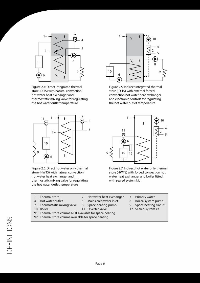
Figure 2.6: Direct hot water only thermalstore (HWTS) with natural convectionhot water heat exchanger andthermostatic mixing valve for regulatingthe hot water outlet temperature
14710V1:V2:
Thermal storeHot water outletThermostatic mixing valveBoilerThermal store volume NOT available for space heatingThermal store volume available for space heating
25811
Hot water heat exchangerMains cold water inletSpace heating pumpDiverter valve
36912
Primary waterBoiler/system pumpSpace heating circuitSealed system kit
1
5
6
7
9
11
3
34
2
10
1
Figure 2.7: Indirect hot water only thermalstore (HWTS) with forced convection hotwater heat exchanger and boiler fittedwith sealed system kit
6
12
11
9
3
10
1
Figure 2.4: Direct integrated thermalstore (DITS) with natural convectionhot water heat exchanger andthermostatic mixing valve for regulatingthe hot water outlet temperature
5
6
7
3V2
V13 V1
3
V2 3
4
2
8
9
8
9
10
Figure 2.5: Indirect integrated thermalstore (IDITS) with external forcedconvection hot water heat exchangerand electronic controls for regulatingthe hot water outlet temperature
5
42
10
1
610
5
42
10

Page 7
DEF
INIT
ION
S
2.2.5 Direct buffer store (DBS)
(a) A thermal store heated directly by one or more boilers in a group-heating scheme (1) shown schematically in figure �.8. In these heating systems, the DBS is used for supplying primary hot water to direct integrated thermal store (DITS) located in the individual dwellings.
(b) The buffer store thermostats control the operation of one or more boilers in a thermal storage group heating scheme.
(c) A direct buffer store does not have a built in heat exchanger for supplying domestic hot water.
Note:
(i) The details of the thermal storage group heating systems are contained in a separate publication.
2.2.6 Indirect buffer store (IDBS)
(a) A thermal store heated indirectly by one or more boilers by means of an internal primary heat exchanger and is used in a group heating scheme (figure �.8) for supplying hot water to direct integrated thermal stores (DITS) located in individual dwellings.
(b) The buffer store thermostats control the operation of one or more boilers in a thermal storage group heating scheme.
(c) An indirect buffer store cannot have a built in heat exchanger for supplying domestic hot water.
1
2345678
Indirect integrated thermalstores in individual dwellingsDirect buffer store (DBS)Indirect buffer store (IDBS)BoilerBoiler pumpBuffer store charge control valveIDBS primary heat exchangerDistribution pump
Figure 2.8: Schematic diagram of a thermal storage group heating scheme
4
1
5
1
4
6
5
3
2
7
8
1
1
86

Page 8
DEF
INIT
ION
S
2.2.7 Integrated thermal stores (DITS & IDITS) for individual dwellings
(a) A typical integrated thermal store (ITS) heating system for an individual dwelling is shown in figure �.9. The design of an ITS for individual dwellings must ensure that:-
• One or more store thermostats control the operation of the boiler and the boiler pump.
• The user space heating controls e.g. a room thermostat, heating programmer, must control the operation of the space heating pump and not the operation of the heat generator.
• It meets the requirements of sections 3 and 4.
(b) Both direct and indirect integrated thermal stores (DITS and IDITS) having either a natural or a forced convection hot water heat exchangers are suitable for individual dwellings.
(c) Thermal stores designed for an open system and for individual dwellings may have an integral or remote feed and expansion tank.
(d) Thermal stores designed for sealed heating (i.e. closed) system and for individual dwellings must be fitted with safety devices and controls specified in the Building Regulations Approved Document G3.
Figure 2.9: Typical integrated thermal store (DITS) based heating system for individual dwellings
1357911131517
Hot water outlet to tapsExpansion Vessel (1)
Heating programmerThermostatic mixing valveBoiler pumpBoiler circuit check valve (2)
Integrated feed and expansion cisternBoiler pump over-run timerHot water heat exchanger check valve
Notes(1)(2)
Expansion vessel can be integral part of the hot water heat exchangerTo be fitted on site if required
246810121416
Mains cold water inletSpace heating pumpRoom thermostatHeating circuit check valve (2)
BoilerStore thermostat/sensorWiring centreMains supply 1 x 230V ac, 50Hz
15 67
9
11
12
17
13
3
4
8
2
10
1514
16

Page 9
DEF
INIT
ION
S
2.2.8 Hot water thermal stores for individual dwellings
(a) Typical heating systems based on direct and indirect hot water only thermal stores (HWTS) are shown in figures �.10 and �.11 respectively. The design of HWTS for individual dwelling must ensure that:-
• If the hot water has priority then the store thermostat controls the operation of the boiler, system pump and the 3-port diverter valve.
• If a flow share arrangement is used then the user space heating controls e.g. a room thermostat, heating programmer, should control the operation of the boiler, system pump and the position of the 3-port diverter valve together with store thermostat.
• It meets the requirements of sections 3 and 4.
(b) Both direct and indirect HWTS designed for individual dwelling may have an integral or remote feed and expansion tank or may be fitted with sealed system components, which must comply with Building Regulations and appropriate British Standards.
Note:
(i) In a heating system incorporating an HWTS, if the domestic hot water has a priority then if space heating is ON and the thermal store control thermostat(s) calls for heat, the space heating is switched OFF until the thermal store is satisfied.
(ii) Compared to an integrated thermal store, an HWTS system increases the boiler cycling when the space heating is ON.
Figure 2.10: Typical direct hot water thermal store (HWTS) based heatingsystem for individual dwellings
15 67
9
4 12
17
1311
3
8
2
15 1416
10
Figure 2.11: Typical indirect hot water thermal store (IHWTS) based heatingsystem for individual dwellings
15 67
9
4
12
17
13
3
8
18
2
15 1416
10
1234567891011
1213
14151617
18
Hot water outlet to tapsMains cold water inletExpansion Vessel (1)
Bypass valveHeating programmerRoom thermostatThermostatic mixing valve3-Port valveBoiler/system pumpBoilerAir vent and anti-vacuum valveStore thermostat/sensorIntegrated feed and expansion cisternWiring centreBoiler pump over-run timerMains supply 1 x 230V ac, 50HzHot water heat exchanger check valveSealed system kit

Page 10
DEF
INIT
ION
S
2.2.9 Integrated thermal stores for group heating
(a) Both direct and indirect integrated thermal stores (DITS and IDITS) with natural or forced convection hot water heat exchangers are suitable for thermal storage group heating systems. Typical configurations of DITS and IDITS for this application are shown in figures �.1� and �.13 respectively.
(b) A thermal store for group heating system does not directly control the operation of the boilers but the store thermostat(s) control the operation of the charge control valve.
(c) A thermal store for group heating system is normally fitted with a metering system for apportioning the running costs.
(d) A direct integrated thermal store (DITS) for a group-heating scheme can not have an integral or remote feed and expansion tank.
(e) An indirect integrated thermal store (IDITS) for a group-heating scheme must have an integral or remote feed and expansion tank or must be suitable for a sealed system and be fitted with appropriate system components.
(f ) Integrated thermal stores (DITS and IDITS) must comply with the requirements of sections 3 and 4.
Figure 2.12:
Figure 2.13:
Typical direct integrated thermal store (DITS) based heating system foran apartment in a group heating scheme
Typical indirect integrated thermal store (IDITS) based heating system foran apartment in a group heating scheme
1234567891011121314
1516171819
Isolating valveIn line filterBalancing valveHeat meterStore charge control valveDistribution networkStore thermostatSpace heating pumpCold water inletHot water outlet to tapsHot water heat exchangerSpace heating circuitWiring and controlsMains electricity supply230V ac, 50 HzHW heat exchanger pumpF & E cisternAir vent / anti-vacuum valveProgrammerRoom thermostat
1
1
18 19
7
7
9
4
12
17
11
35
8
6
2
14
10
15
16
13
1
17 9
4
11
35
8
6
2
10
15

Page 11
DEF
INIT
ION
S
2.2.10 Hot water only thermal stores (HWTS) for group heating
(a) Only indirect hot water only thermal stores are suitable for group or district heating systems. Typical configuration for the application is shown in figure �.14.
(b) A hot water thermal store does not control the operation of the central boilers directly but the store thermostat(s) control the operation of the charge control valve.
(c) A HWTS for group heating scheme may be fitted with a metering system for apportioning the running costs.
(d) Hot water thermal store must comply with the requirements of sections 3 and 4.
16 17
7
8
11
10
13
9
14
15
7
Vp
12
1
1
4
3 5
5
6
2
Figure 2.14: Typical indirect hot water only thermal store (HTS) based heating systemfor an apartment in a group heating scheme
1357911131517
Isolating valveBalancing valveStore charge control 3-port valveStore thermostatHot water outlet to tapsSpace heating circuitMains electricity supply 230V ac, 50HzF & E cisternRoom thermostat
246810121416
In line filterHeat meterDistribution networkCold water inletHot water heat exchangerWiring centre and controlsHW heat exchanger pumpProgrammer

Page 1�
3.1 THERMAL STORE DATA BADGE
The following minimum information shall be provided in the form of a Data Badge fixed to the thermal store. The badge must be accessible without the use of tools.
• Section 3.1.1 applies to all types of thermal stores i.e. DITS, IDITS, HWTS, DBS and IDBS.
• Section 3.1.� applies to direct and indirect integrated thermal stores (DITS and IDTS) and both direct and indirect hot water thermal stores (HWTS).
• Section 3.1.3 applies to indirect integrated thermal stores (IDITS), indirect hot water thermal stores and indirect buffer stores (IDBS).
3.1.1 For all types of thermal stores
(a) Manufacturers name and address etc. [….](b) Complies with Performance Specification for
Thermal Stores [….](c) The model and identity number […](d) Primary water storage capacity (l)(e) Maximum working head for the store [bar](f ) Maximum working temperature (if special
components fitted) [°C](g) Store thermostat settings [°C]
3.1.2 Additional data for integrated thermal stores
(a) Maximum working pressure for hot water heat exchanger [bar]
(b) Code-A (Coded information as defined in appendix D)
3.1.3 Additional data for indirect stores
(a) Maximum working pressure for primary heat exchanger [bar]
(b) Code B (Coded information as defined in appendix D)
3.2 THERMAL STORE SYSTEM DESIGN AND INSTALLATION MANUAL
These manuals should be provided with all thermal stores and should include (where appropriate) the following information:-
(a) Performance and design information as defined in appendix E of this document.
(b) Installation and service instructions with examples.
(c) Recommended space heating system designs and control.
(d) Recommended hot and cold water distribution networks in a dwelling (e.g. supply to shower and pipe sizes).
3.3 FLOW AND RETURN CONNECTIONS
(a) These should be designed to prevent short circuit of flow and return in the store for both the boiler circuit and the space heating circuit.
(b) The aim should be to achieve uniform flow (up or down) across the diameter of the store. This can be achieved by using sparge pipes, diffusers or other similar methods.
3.4 THERMOSTAT POCKETS
(a) The thermostat pocket should be designed and located to sense the bulk water temperature in the active zone of the store.
(b) Thermal stores of capacity up to �10 litres should be fitted with ONE store thermostat pocket and thermal stores of capacity greater than �10 litres should be fitted with TWO thermostat pockets as shown in figure 3.1.
(c) The position of the store thermostat pockets must comply with equation � or 3a and 3b.
For VS < 210l; 0.25 V
S < V
B < 0.35V
S ..... (2)
For VS > 210l; 0.05 V
S < V
B < 0.10V
S ..... (3a)
0.60 VS < V
T < 0.70V
S ..... (3b)
GEN
ERAL
REQ
UIR
EMEN
TS

Page 13
GEN
ERAL
REQ
UIR
EMEN
TS
(d) The two store thermostats should be wired as shown in figure 3.� so that the boiler only fires when both thermostats are calling for heat and continue to fire until both thermostats are satisfied. (Note: The same control action should be achieved by electronic logic if non-mechanical thermostats are used.)
3.5 LABELLING OF CONNECTIONS
(a) The thermal store should have clearly labelled connections where applicable for:-
• Boiler or system flow• Boiler or system return• Heating circuit flow• Heating circuit return• Mains cold water inlet• Domestic hot water outlet• Cold feed and open vent• Automatic air vent and anti-vacuum valve• Pictorial labelling of components is acceptable
provided it is securely fixed to the thermal store.
3.6 SIZE AND TYPE OF CONNECTIONS
(a) The pipe connections should be designed to minimise the heat losses from the thermal store.
(b) The size of connections will depend upon the capacity and the type of store. Normally ��mm for stores up to 140 litres, �8mm for stores up to �10 litres, 35mm for stores up to 350 litres and 4�mm for stores up to 500 litres will be adequate.
3.7 DESCALING OF HOT WATER HEAT EXCHANGER
A means of descaling the hot water heat exchanger in the field must be provided and the procedure must be outlined in the design and installation manuals.
Where:-
VS = Nominal storage capacity of a thermal store (l)
VB = Volume of water below store thermostat _ 1 (l)
VT = Volume of water below store thermostat _ 2 (l)
VB = 0.25VS
VB = 0.35VS
VS_ 210 litres<
VB
1
Figure 3.1: Position of store temperature controlthermostats or sensors
12
VSVBVT
Lower store thermostatTop store thermostat
= Volume of the thermal store= Volume of water below store thermostat 1= Volume of water below store thermostat 1
VB = 0.05VS
VB = 0.10VS
VS > 210 litres
VB
1
VT = 0.60VS
VT = 0.70VS
VT
2
1
Figure 3.2: Schematic wiring diagram for twin thermostat control of thermal stores
L
SL
3
L
N
14
Bottom thermostatPump over run timer
25
Top thermostatBoiler pump
36
2-Pole CO relayBoiler
2
4
5
6

Page 14
PERF
ORM
ANCE
SPE
CIFI
CATI
ON
4.1 DOMESTIC HOT WATER PERFORMANCE
4.1.1 General requirements
(a) The requirements of sections 4.1.�., 4.1.3 and 4.1.4 apply to both the direct and indirect integrated thermal stores and the hot water thermal stores (DITS, IDITS and HWTS) having forced or natural convection heat exchangers defined in section � of this document.
(b) For both individual dwellings and group heating applications, the hot water flow rate and volume are related to the type of dwelling for which a thermal store is designed.
(c) The hot water performance of a thermal store should be measured using a test rig and test procedures set out in appendix A of this document. The flow rates and draw-off volumes listed in table 1 should be used for these tests.
4.1.2 Hot water performance without hot water temperature control device
The domestic hot water performance of a thermal store should be measured without a thermostatic mixing valve or a similar temperature regulating device using the procedures and tests A1 and A� set out in appendix 1 of this document.
(a) The average temperature rise of the hot water draw-off of a specified volume and the specified flow rate must not be less than 45°C and 40°C for tests A1 and A� respectively (see table �).
(b) The temperature rise of the hot water from a thermal store at the end of a draw-off must not be less than 35°C in the tests A1 and A�.
4.1.3 Hot water performance without hot water temperature control device
The effectiveness of a thermostatic mixing valve or a similar device in preventing a hot slug of water reaching an outlet should be measured using the test procedure A3 in appendix A.
(a) The maximum peak temperature and the volume of the hot slug (see section �.1.7) shall not be more than the values specified in table 3.
(b) The hot water performance of the thermal store with and without a mixing valve or other temperature regulating device (set at 55°C) should be presented as shown in figure A� in the installation and design manual of that store.
4.1.4 Pressure loss of hot water heat exchanger
(a) The pressure loss measurements of the domestic hot water heat exchanger (internal or external) should be carried out using the test procedure A4, defied in appendix A.
(b) The pressure loss at nominal water flow rate given in table 1, should be declared on the store data badge in the coded form.
(c) Full pressure flow characteristics of the hot water heat exchanger should be presented in the design manual in the format shown in figure A3.
Table 1 : Hot water draw-off volumes and flow rates
Thermal store
classification
Type of thermal store
Draw-off volume (l)
Draw-off flow rate
(l/s)*
SC1: Dwellings
For showers only
40 0.13
SC�: Dwellings
For 1 bathroom
67 0.30
SC3: Dwellings
For � bathrooms
133 0.50
* Normal flow rate (QN)
Table � : Minimum average temperature rise of hot water draw-off
Test schedule (Appendix 1)Minimum average
temperature rise of a draw-off
A1: No heating load 45°C
A�: Design heating load 40°C
Table 3: Maximum peak temperature and volume of hot slug of water at draw-off point.
Flow rate (l/s)Maximum peak
temperature (°C)Maximum volume
of hot slug (l)
0.1 65 0.15
0.� 65 0.�0
0.3 65 0.�5
0.5 65 0.30

Page 15
PERF
ORM
ANCE
SPE
CIFI
CATI
ON
4.2 PERFORMANCE OF PRIMARY HEAT EXCHANGER
4.2.1 General
(a) The requirements of this section apply to both the indirect integrated thermal store (IDITS) and the indirect buffer store (DBS) as defined in section �.
(b) The test rig and the test procedure for measuring the performance of the primary heat exchanger of indirect stores are defined in appendix B.
4.2.2 Heat transfer capacity of primary heat exchanger
(a) The UA value i.e. the heat transfer capacity of the primary heat exchanger shall be determined using the test procedure B1 outlined in appendix B.
(b) The nominal flow rate (QN) and the UA value for
an average temperature difference of 6°C shall be declared on the store ‘data badge’ in the coded form.
The complete design data as shown in figure B� shall be presented in the design manual.
4.2.3 Pressure loss of primary heat exchanger
(a) The hydraulic characteristics of the primary heat exchanger should be measured using the test procedure, B� outlined in appendix B.
(b) The nominal flow rate (QN) and the pressure loss
at the nominal flow rate shall be declared on the store ‘data badge’ in the coded form.
The full design information in form shown in figure B3, shall be presented in the system design manual for the store.
4.3 STANDBY HEAT LOSS FROM A THERMAL STORE AND ENERGY RATING
4.3.1 General
(a) This section applies to all types of thermal stores including buffer stores.
(b) The �4-hour average heat loss rate QHL
, measured using the test rig (figure C1) and the procedure C� and C3 given in appendix C, shall not be greater than the value, Q
HL-MAX, given by equation
4. Alternatively, the maximum permitted heat loss rate, Q
HL-MAX, can be read from figure 4.
QHL-MAX
= 1.6 x [0.2 + (0.051 x (VS)2/3] ---- (4)
Where:-
QHL-MAX
= Maximum permitted heat loss from a thermal store [kWh/24h] V
S = Declared capacity of thermal store (l)
Note:
(i) This figure should be regarded as an absolute maximum and efforts should be made to reduce it.
(ii) The actual measured value shall be declared on the data badge in the coded form and also in the appliance manuals etc.

Page 16
PERF
ORM
ANCE
SPE
CIFI
CATI
ON
4.3.2 Heat loss for SAP calculations
The In-Use heat losses from thermal stores will be less than the measured values (see 4.3.1. This is because:-
(a) The thermal stores are normally installed in airing cupboards like a conventional cylinder. Therefore, the ambient temperature will be higher than �0°C specified for the test procedures and therefore the heat losses will be lower.
(b) The thermal storage systems are now being installed with two channel programmers for controlling both space heating and hot water. Therefore, the thermal store is not maintained at nominal maximum temperature of 75°C. When the boiler is not charging the thermal store, it will provide 40-50% of hot water demands in a dwelling resulting in a significantly lower �4h mean store temperature.
(c) The field studies have shown that the usage pattern of thermal storage heating systems is similar to that for conventional systems.
(d) Unlike the integrated thermal stores, the hot water only thermal stores are not maintained at high temperature when space heating is on.
Figure 4 : Maximum permitted heat loss from a thermal store
0.0
1.0
2.0
3.0
4.0
5.0
6.0
0 100 200 300 400 500 600
Nominal volume (litres)
Heat
loss
rate
(kW
h/2
4h)
4.3.2 Heat loss for SAP calculations
The In-Use heat losses from thermal stores will be less than the measured values (see 4.3.1. This is because:-
(a) The thermal stores are normally installed in airing cupboards like a conventional cylinder. Therefore, the ambient temperature will be higher than 20oC specified for the test procedures and therefore the heat losses will be lower.
(b) The thermal storage systems are now being installed with two channel programmers for controlling both space heating and hot water. Therefore, the thermal store is not maintained at nominal maximum temperature of 75oC. When the boiler is not charging the thermal store, it will provide 40-50% of hot water demands in a dwelling resulting in a significantly lower 24h mean store temperature.
(c) The field studies have shown that the usage pattern of thermal storage heating systems is similar to that for conventional systems.
(d) Unlike the integrated thermal stores, the hot water only thermal stores are not maintained at high temperature when space heating is on. Therefore its 24h average heat loss is lower than ITS.
The heat loss factors for Hot Water Only and Integrated Thermal Stores (HWS and ITS) for use in SAP procedures must be calculated using appropriate equations as detailed in the separate loose sheet contained at the back of this document.
HWA Specification for thermal stores Draft: ID_01/010208 21/43
Therefore its �4h average heat loss is lower than ITS.
The heat loss factors for Hot Water Only and Integrated Thermal Stores (HWS and ITS) for use in SAP procedures must be calculated using appropriate equations as detailed in the separate loose sheet contained at the back of this document.
4.4 WATER TEMPERATURE IN AN INTEGRATED FEED AND EXPANSION TANK
4.4.1 This section applies to all thermal stores fitted with an integral feed and expansion tank. The �4-hour average temperature of water in the feed and expansion tank during the heat loss measurements (see appendix C).
4.4.2 The measured average temperature of the water in the feed and expansion tank should not exceed 50°C.
4.4.3 The design of the feed and expansion tank, the lid and the overflow pipe connection (e.g. dipped) should be such that the water loss due to evaporation is minimised.

Page 17
SPEC
IFIC
ATIO
N O
F CO
MPO
NEN
TS
5.1 GENERAL
The integrated thermal store can either be supplied with all the components ready fitted and wired or full wiring details and list of recommended components (e.g. pumps, delay timers) must be provided.
5.2 Store thermostat(s)
5.2.1 The specified store thermostat setting should prevent the boiler cycling on its internal thermostat for efficient operation.
5.2.2 All types of thermal stores must be supplied with one or more thermostats with an adjustable range of up to 90°C and span not greater than 70°C. The switching differential of the thermostat should be 6±1°C.
5.2.3 A strap on surface cylinder thermostat is not considered suitable for this application.
5.2.4 The store control thermostats should be either:-
(a) Non user adjustable and pre-set to switch off at the specified temperature to guarantee the performance.
Or(b) Capable of being locked in the correct user
zone and should switch off at the specified temperatures within the zone to guarantee the performance.
5.2.5 The thermal stores of capacity greater than �10 litres shall be fitted with two thermostats and wired as shown in figure 3.� to switch a boiler or a zone valve.
5.3 DOMESTIC HOT WATER BACK EXPANSION
5.3.1 The thermal stores DITS, IDITS and HWTS must be supplied with a suitable expansion vessel for the domestic hot water heat exchanger if necessary.
5.3.2 This expansion vessel is required to accommodate the expansion of water (due to heating) in the heat exchanger because expansion back in to the mains may not always be possible. (For example, a double check valve may be fitted in the mains supply).
5.3.3 The method and equipment provided or specified for accommodating the expansion must comply with the Model Water Bylaws and relevant standards.
5.4 HOT WATER TEMPERATURE CONTROL DEVICE
5.4.1 Direct and indirect integrated thermal stores (DITS and IDITS) and hot water thermal stores (HWTS) must be supplied with a domestic hot water outlet temperature regulating device to prevent a hot slug reaching the hot water outlets.
5.4.2 The performance of the hot water temperature control device must meet the requirements of section 4.1.�.
5.5 PUMP OVER-RUN CONTROL
5.5.1 If an integrated thermal store intended for an individual dwelling is used with a boiler that requires pump over-run, then it must be supplied with a suitable additional pump over-run delay timer or similar device.
5.5.2 The normal boiler flow temperature sensing thermostat used in majority of boilers to control the pump over-run is not suitable for this application.
5.5.3 Integrated thermal stores for group heating applications do not require a pump over-run delay timer.
5.6 ANTI-VACUUM AND AIR RELEASE VALVE(S)
5.6.1 Direct integrated thermal stores (DITS) intended for group heating schemes must have connections for fitting an air vent and anti-vacuum valves. These items must be supplied with the store.
5.6.2 Indirect integrated thermal stores (DITS) may be supplied without these devices.
5.7 2-PORT MOTORISED CHARGE CONTROL (I.E. ZONE) VALVE
5.7.1 An integrated thermal store (DITS and IDITS) that is intended for group heating scheme must be supplied with a �-port motorised (zone) valve controlled by the store thermostats (figures �.1� and �.13).
5.7.2 The performance specification of this valve e.g. maximum working pressure differential and flow rate must be included in the installation and design instructions.
Page 18
SPEC
IFIC
ATIO
N O
F CO
MPO
NEN
TS
5.8 METERING SYSTEMS
5.8.1 Unless the customer specifies otherwise, an integrated thermal store that is intended for group-heating scheme must be supplied with a metering system for apportioning the running costs.
5.8.2 Typical metering options are:-
(a) Heat meter for recording the heat energy delivered to the thermal store in the individual dwelling.
(b) Timer based devices for recording the length of time the zone valve is open i.e. the store has received heat.
(c) Volume based devices for recording the volume of hot water delivered to the thermal store in the individual dwellings from the central boiler plant.
5.8.3 Details of the metering systems are set out in a Watson House publication ‘Thermal Storage Group Heating Design Guide’.

Page 19
APPE
ND
IX A
Test rig and the test procedures for evaluating the performance of a hot water heat exchanger of an integrated store (DITS and IDITS) and hot water thermal store (HWTS).
A1 TEST RIG AND TEST CONDITIONS
The schematic layout of the test rig for determining the hot water performance of direct and indirect integrated thermal stores (DITS and IDITS) and hot water thermal stores (HWTS) is shown below in figure A1.
The hot water performance of the thermal store should be presented in the graphical form as shown in figure A�.
A1.1 Either a gas boiler or an in-line electric heater heats a thermal store under test. A mixing pump is used to ensure that the thermal store is heated uniformly from top to bottom. Alternatively, an immersion heater may be used to heat the
thermal store but a mixing pump would still be required.
A1.� A manometer or pressure gauges may be used for measuring the pressure drop across the domestic hot water heat exchanger.
A1.3 Although the cold water inlet temperature during a test can be allowed to vary between 9°C and 11°C, the average temperature over a complete draw-off should be 10±0.5°C.
A1.4 The maximum uncertainty in the measurement of water temperature should not exceed ±0.�5°C.
A1.5 The maximum uncertainty in the measurement of the draw-off volume and the draw-off flow rate should not exceed ±0.5 litres/minute respectively.
A1.6 The maximum uncertainty in the measurement of pressure drop across the heat exchanger should not exceed 3% of the measured value.
T33m of 22mm copper pipe(0.95 / minimum volume)
V17
8
6
5
4
V2T1 P1
T43
1
9
2
T2
T5
P2
123456789V1:V2:T1 - T5:P1 - P2:
Thermal store under testGas or electric boiler for heating a thermal storeAlternative internal heat source for heating a thermal storeHot water temperature control device e.g. thermostatic mixing valve (Test A3 only)Volume flow rate meter - Should be calibrated and certifiedCold water inlet as 10±1°CVolume measurement (An alternative method)Weighing machineMixing pumpOn/Off valveRegulating valveTemperature sensors immersed in waterPressure measuring points
Figure A1: Test rig for measuring the hot water performance of a thermal store

Page �0
APPE
ND
IX A
A2 TEST_A1 : Hot water performance without domestic hot water temperature control device and no space heating load.
This test applies to the following thermal stores with natural or forced convection heat exchangers:-
• Direct integrated thermal store (DITS)• Indirect integrated thermal store (IDITS)• Hot water thermal store (HWTS)
The object of this test is to determine the performance of the hot water heat exchanger without temperature regulating device (e.g. thermostatic mixing valve) and with no simulated design space heating load.
A2.1 Test procedure
A�.1.1 Before a hot water test is started, the temperature of the water in the store at both top and bottom (figure A1) should be 75±0.5°C and stable.
A�.1.� For thermal stores having a natural convection heat exchanger, the boiler or an electric heater, the boiler pump and the mixing pump are switched off before commencing a test and the charge circuit is isolated.
A�.1.3 The cold water inlet and the hot water outlet temperatures shall be continuously recorded at intervals not greater than 10 seconds during a test so that the average temperature rise can be calculated to an accuracy of ±0.5°C.
A�.1.4 The hot water draw-off tests without the temperature control device should be carried out at flow rate specified in table 1.
A�.1.5 The hot water draw-off should be continued until at least the appropriate volume stated in table 1 has been drawn off.
A�.1.6 The average temperature rise of a hot water draw-off shall not be less than 45°C (see table �). In addition, the temperature rise of the hot water at the end of the draw-off shall not be less than 35°C.
A2.2 Hot water heat exchanger rating
A�.�.1 The rating of the hot water heat exchanger for the specified draw-off volume at the specified draw-
off rate should be calculated as shown below in equation a1.
A�.�.� The calculated rating of the heat exchanger should be declared on the ‘data badge’ in the coded form and in the design manual.
HR.W
= (CPρ Q
W(T
AH – T
AC)/1000 ---- (a1)
Where:-
HR.W
= Rating of hot water heat exchanger (kW)þ = Average density of water (kg/m3)Cp = Average specific heat of water (kj/kgoC)Q
W = Average water flow rate (l/s)
TAH
= Average hot water outlet temperature (°C)T
AC = Average cold water inlet temperature (°C)
A3 TEST A2 : HOT WATER PERFORMANCE WITHOUT HOT WATER TEMPERATURE CONTROL DEVICE AND WITH SIMULATED SPACE HEATING LOAD.
This test applies to the following thermal stores with natural or forced convection heat exchangers:-
• Direct integrated thermal store (DITS)• Indirect integrated thermal stores (IDITS)
The object of this test is to determine the performance of the hot water heat exchanger when the space heating is switched on and the space-heating pump is cycling on the room thermostat. Under these conditions, the hot water in the bottom of the thermal store is periodically replaced by the cold water from the space heating circuit (e.g. radiators) and thus reducing the average temperature of the water in the thermal store.
A3.1 Initial store charge temperature
The initial store charge temperature for this test is calculated from the equation a�.
TSC
= (75VS – 120Q
R)/V
S ---- (a2)
Where: -
TSC
= Initial store charge temperature (°C) V
S = Volume of thermal store under test (l)
QR = Maximum recommended radiator capacity
for the test store (kW)
Page �1
APPE
ND
IX A
A3.2 Test procedure
A3.�.1 The test procedure is the same as for test A1 described in section A� but before a hot water test is started, the temperature in the store at both the top and the bottom (see figure A1) should be equal to T
SC±0.5°C.
A3.�.� For thermal stores with natural convection domestic hot water heat exchangers, the boiler or an electric heater, the boiler (heat source) pump and the mixing pumps are switched off and the charge circuit is isolated before commencing a test.
A3.�.3 If a thermal store has forced convection heat exchanger, then an appropriate circulation pump is allowed to run but no heat input is allowed during the hot water draw-off.
A3.�.4 The cold water inlet and the hot water outlet temperatures shall be continuously recorded at intervals not greater than 10 seconds during a test so that the average temperatures can be calculated to an accuracy of ±0.5°C.
A3.�.5 The hot water draw-off test shall be carried out at flow rates specified in table 1.
A3.�.6 The hot water draw-off shall be continued until at least the volumes stated in table 1 have been drawn off.
A3.�.7 The average temperature rise of a hot water draw-off shall not be less than 40°C (see table �) and also the temperature rise of the hot water at the end of a draw-off shall not be less than 35°C.
A4 TEST A3: Hot water performance with a hot water temperature control device and no simulated space-heating load.
This test applies to the following thermal stores with natural or forced convection heat exchangers:-
• Direct integrated thermal store (DITS)• Indirect integrated thermal store (IDITS)• Hot water thermal store (HWTS)
The object of this test is to assess the effectiveness of a domestic hot water temperature control device (e.g. a thermostatic mixing valve) in preventing the hot slug of water at temperature greater than 60°C reaching a draw-off point.
A4.1 Test conditions
A4.1.1 For these tests, the domestic hot water temperature control device e.g. a thermostatic mixing valve should be set to control at 55°C.
A4.1.� The average store charge and the cold water inlet temperatures should be 75°C and 10°C respectively (as per previous tests).
A4.1.3 The volume of water in the draw-off pipe from the thermal store to the tap (i.e. the dead leg) should be 1±0.1 litres.
A4.1.4 The temperature of the water in the dead leg should be �0±�°C before commencing a hot water draw-off test.
A4.1.5 Fast acting recorders and temperature sensors must be used for this test. For example unsheathed thin wire thermocouples.

Page ��
A4.�.3 The data for the nominal test flow rate should be presented as shown in figure A� in the system design and installation manual for that store.
A4.�.4 The volume and the average temperature of the hot slug of water should not exceed the values presented in table 3.
APPE
ND
IX A
A4.2 Test procedure
A4.�.1 This test should be carried out at all of the flow rates specified in table 3, section 4.1.�.
A4.�.� The hot water draw-off test should be started by opening the valve V1 (figure A1) and the hot water outlet temperature T
3 and T
4 (see figure
A1) are continuously recorded to determine the volume and the temperature of the hot water slug.
A4.2 Test procedure
A4.2.1 This test should be carried out at all of the flow rates specified in table 3, section 4.1.2.
A4.2.2 The hot water draw-off test should be started by opening the valve V1 (figure A1) and the hot water outlet temperature T3 and T4 (see figure A1) are continuously recorded to determine the volume and the temperature of the hot water slug.
A4.2.3 The data for the nominal test flow rate should be presented as shown in figure A2 in the system design and installation manual for that store.
A4.2.4 The volume and the average temperature of the hot slug of water should not exceed the values presented in table 3.
Figure A2: Example of presentation of hot water performance of athermal store
0
10
20
30
40
50
60
70
80
0 2 4 6 8
Time and draw-off volume
Tem
per
ature
oC
10
With mixing valveWithout mixing valve
A5 TEST A4 : MEASUREMENT OF PRESSURE LOSS THROUGH THE HOT WATER HEAT EXCHANGER
This test applies to the following thermal stores with natural or forced convection heat exchangers:-
Direct integrated thermal store (DITS) Indirect integrated thermal stores (IDITS) Hot water thermal stores (HWTS)
A5.1 The pressure loss across the hot water heat exchanger should be measured without the inline temperature control device (e.g. thermostatic mixing valve) and when the store temperature is cold i.e. with no significant extraction of heat.
A5.2 The cold water inlet temperature should be 10+0.5oC.
HWA Specification for thermal stores Draft: ID_01/010208 30/43
With mixing valveWithout mixing valve

Page �3
APPE
ND
IX A
A5 TEST A4 : MEASUREMENT OF PRESSURE LOSS THROUGH THE HOT WATER HEAT EXCHANGER
This test applies to the following thermal stores with natural or forced convection heat exchangers:-
• Direct integrated thermal store (DITS)• Indirect integrated thermal stores (IDITS)• Hot water thermal stores (HWTS)
A5.1 The pressure loss across the hot water heat exchanger should be measured without the inline temperature control device (e.g. thermostatic mixing valve) and when the store temperature is cold i.e. with no significant extraction of heat.
A5.2 The cold water inlet temperature should be 10±0.5°C.
A5.3 The pressure loss should be measured at the following flow rates. Q
N is the nominal domestic
hot water flow rate for the thermal store under test.
(a) 0.5QN
(b) 0.75QN
(c) QN
(d) 1.10QN
(e) 1.�5QN
A5.4 The data should be presented in the design manual in a graphical form as shown in figure A3.
A5.5 The pressure loss at nominal flow rate, QN, should
be declared on a thermal store ‘data badge’.
A5.3 The pressure loss should be measured at the following flow rates. QN is the nominal domestic hot water flow rate for the thermal store under test.
(a) 0.5QN
(b) 0.75QN
(c) QN
(d) 1.10QN
(e) 1.25 QN
A5.4 The data should be presented in the design manual in a graphical form as shown in figure A3.
A5.5 The pressure loss at nominal flow rate, QN, should be declared on a thermal store ‘data badge’.
Figure A3 : Example of presentation of pressure losscharacteristics of hot water heatexchanger
0
0.1
0.2
0.3
0.4
0.5
0.6
0.7
0.8
0.9
1
0 0.2 0.4 0.6 0.8 1 1.2 1.4
Flow rate x QN (l/s)
Pres
sure
dro
p (
bar
) QN = Nominal design flow rate
HWA Specification for thermal stores Draft: ID_01/010208 31/43

Page �4
APPE
ND
IX B
Test rig and the test procedures for evaluating the performance of a primary heat exchanger of an indirect integrated thermal stores (IDITS) and an indirect buffer store (IDBS)
B1 TEST RIG AND TEST CONDITIONS
B1.1 The schematic layout of the test rig for determining the rating of the heat exchanger used for heating indirect integrated thermal stores and indirect buffer stores is shown in figure B1.
B1.2 The indirect thermal store under test should be heated by passing hot water from a pre-heated tank at a constant temperature and flow rate to determine the UA value (i.e. the capacity) of the heat exchanger.
B1.3 The maximum uncertainty of in the measurement of temperatures should not exceed ±0.�°C. The maximum uncertainty in the measurement of flow rate through the heat exchanger should not exceed ±1.5%.
B1.4 If a certified accurate flow meter is not available then the continuous weighing of the water as shown in figure B1 may be used.
B1.5 The maximum uncertainty in the measurement of pressure loss across the heat exchanger should not exceed 3% of the measured value.
12345678910V1:V2:T1 - T6:P1 - P2:
Thermal store under testGas or electric boiler for heating a thermal storeAlternative internal heat source for heating a thermal storeStore mixing pumpVolume flow rate meter - Should be calibrated and certifiedCold water inlet when weighing method is used for measuring the flow rateVolume measurement (An alternative method)Weighing machineHot water storage vesselDiverter valveOn/Off valveRegulating valveTemperature sensors immersed in waterPressure measuring points
Figure B1: Test rig for measuring the performance of a primary heat exchanger of anindirect thermal store
7
8
P1 T1
T43
9
4
2
T3
P2 T2T4
T5
6
54
10
1

Page �5
APPE
ND
IX B
B2 TEST B1 : DETERMINING THE UA-VALUE OF THE PRIMARY HEAT EXCHANGER
This test applies to indirect integrated thermal store (IDITS) and indirect buffer store (DBS).
B2.1 Test procedure
B�.1.1 Heat the thermal store with the mixing pump on to a uniform temperature of 65±0.5°C.
B�.1.� The hot water storage tank shall be heated to supply hot water at 8�±1°C during the test.
B�.1.3 Set the flow rate, Q, through the primary heat exchanger to the nominal charge flow rate, Q
N, for
the store under test and stop the mixing pump.
B�.1.4 Start heating the thermal store and at one-minute (60s) intervals read and record flow and return temperatures (T
1 and T
�) and the flow rate, Q.
B�.1.5 Continue the test until the difference between flow and return temperatures, T
1 and T
� is
4±0.5°C.
B�.1.6 Repeat the tests (steps 1-5) at maximum charge flow rate, Q
MAX and at minimum charge flow rate
QMIN
.
Where:-
QMAX
= 1.5 QN
QMIN
= 0.5 QN
Note: If a certified reference flow meter is not used then the primary water flow should be directed to the weighing machine and the readings taken every minute to determine the average flow rate.
B2.2 Calculations and presentation of results
B�.�.1 The instantaneous UA-Value i.e. the heat exchanger capacity should be calculated for every time step using equations b1-b7 and presented in the system design and installation manual as shown in figure B�.
B�.�.� The UA-Value of the heat exchanger at nominal flow rate, Q
N, and for an average temperature
difference of 6°C should be declared on the store ‘data badge’.
Q = (Qt1 _Q
t2)/2 (b1)
TA1
= (T1.t1
+ T1.t2
)/2 (b2) T
A2 = (T
2.t1 + T
2.t2)/2 (b3)
TW
= (TA1
+TA2
)/2 (b4) T
S.t2 = T
S.t1 + ((QρC
P(T
A1-T
A2)/δt)/V
SρC
p) (b5)
TS = (T
S.t1 + T
S.t2)/2 (b6)
UA = (QρCP(T
A1-T
A2)/δt/(T
W – T
S) (b7)
Where:-
Q = Average flow rate through the primary heat exchanger (l/s)Q
t1 = Flow rate through the primary
heat exchanger at time, t1 (l/s)Q
t2 = Flow rate through the primary heat
exchanger at time, t2 (l/s)T
A1 = Average flow temperature to
primary heat exchanger (°C)T
1.t1 = Flow temperature to primary
heat exchanger at time, t1 (°C)T
1.t2 = Flow temperature to heat
exchanger at time, t2 (°C)T
A2 = Average return temperature from
primary heat exchanger (°C)T
2.t1 = Return temperature from heat
exchanger at time, t1 (°C)T
2.t2 = Return temperature from heat
exchanger at time, t2 (°C)T
W = Average primary water
temperature (°C)T
s.t1 = Average store temperature
at time, t1 (°C)T
s.t2 = Average store temperature
at time, t2 (°C)ρ = Average density of water (kg/m3)C
p = Average specific heat of water (kj/kg°C)
δt = Time interval (t2-t1) (s)V
S = Volume of thermal store
under test (l)T
S = Average temperature of
thermal store (°C)UA = Heat exchanger capacity (W/°C)

Page �6
APPE
ND
IX B
B3 TEST B2 : PRESSURE LOSS MEASUREMENTS OF THE INDIRECT (PRIMARY) HEAT EXCHANGER
B3.1 The pressure drop across the primary indirect heat exchanger should be measured at an average of flow and return temperature of 70±�°C at the following flow rates:-
B3.1.1 0.50 QN
B3.1.� 0.75 QN
B3.1.3 QN
B3.1.4 1.10QN
B3.1.5 1.�5QN
Where:-
Q = Average flow rate through the primary heat exchanger (l/s)Qt1 = Flow rate through the primary heat exchanger at time, t1 (l/s)Qt2 = Flow rate through the primary heat exchanger at time, t2 (l/s)TA1 = Average flow temperature to primary heat exchanger (oC)T1.t1 = Flow temperature to primary heat exchanger at time, t1 (oC)T1.t2 = Flow temperature to heat exchanger at time, t2 (oC)TA2 = Average return temperature from primary heat exchanger (oC)T2.t1 = Return temperature from heat exchanger at time, t1 (oC)T2.t2 = Return temperature from heat exchanger at time, t2 (oC)TW = Average primary water temperature (oC)Ts.t1 = average store temperature at time, t1 (oC)Ts.t2 = Average store temperature at time, t2 (oC)
= Average density of water (kg/m3) Cp = Average specific heat of water (kj/kgoC)t = Time interval (t2-t1) (s)
VS = Volume of thermal store under test (l)TS = Average temperature of thermal store (oC)UA = Heat exchanger capacity (W/oC)
Figure B2: Example of a presentation of the primary heat exchangerof an indirect thermal store
0
10
20
30
40
50
60
70
80
90
0 5 10 15 20
Average temperature difference (Tw - Ts), oC
UA v
alue
(W
/oC)
0.5QN QN 1.5QN
B3 TEST B2 : PRESSURE LOSS MEASUREMENTS OF THE INDIRECT (PRIMARY) HEAT EXCHANGER
B3.1 The pressure drop across the primary indirect heat exchanger should be measured at an average of flow and return temperature of 70+2oC at the following flow rates:-
B3.1.1 0.50 QN
B3.1.2 0.75 QN
B3.1.3 QN
B3.1.4 1.10QN
B3.1.5 1.25QN
HWA Specification for thermal stores Draft: ID_01/010208 34/43
B3.2 The data should be presented in a system design manual in the format shown in figure B3. The data at nominal primary flow rate, Q
N, through
the heat exchanger should be declared on the thermal store ‘data badge’.
B3.2 The data should be presented in a system design manual in the format shown in figure B3. The data at nominal primary flow rate, QN, through the heat exchanger should be declared on the thermal store ‘data badge’.
Figure B3 : Example of presentation of pressure losscharacteristics of primary heatexchanger
0
0.1
0.2
0.3
0.4
0.5
0.6
0.7
0 0.2 0.4 0.6 0.8 1 1.2 1.4
Flow rate x QN (l/s)
Pres
sure
dro
p (
bar
) QN = Nominal design flow rate
HWA Specification for thermal stores Draft: ID_01/010208 35/43

Page �7
test applies to all types of thermal stores (i.e. integrated, hot water only and buffer stores).
C1.2 During this test, all exposed pipe work, which is integral part of a thermal store, should be insulated as recommended in the installation instructions supplied with the test sample.
C1.3 If the thermal store (e.g. ITS & HWTS) is fitted with an external hot water heat exchanger as shown in figure C1.1 then it should be tested with this heat exchanger and the associated components.
APPE
ND
IX C
Test rig and the test procedures for measuring the standby heat loss of a thermal store and the temperature of the water in the integrated feed and the expansion tank (if fitted).
C1 GENERAL
C1.1 The objectives of this test are to determine the standby heat loss from a thermal store and the temperature of water in the integral feed and expansion cistern (if fitted) at reference test conditions without any components fitted. This
Figure C1.1 Thermal stores fittedwith external hot water heat exchangershould be tested with it and itsassociated components fitted
CW in
HW out
HW heat exchanger
ITS
Figure C1: Schematic diagram of heat loss test rig
25±5mm
450±100
h/2
h
2
4
3
1TFE
TA1
TW
TA2
350±25mm
_700mm>
_700mm>
TA1
TA3
TA2
13
Integral feed & expansion cisternBoiler control or solar controllersensor pocket
24
Thermal store under testImmersion heater

Page �8
APPE
ND
IX C
C2 TEST RIG AND TEST SAMPLE
C2.1 The standing heat loss measurement test shall be performed on a thermal store (i.e. primary water storage vessel of types covered by this document) fitted with a horizontally mounted immersion heater or a fixed electrical element of 3kW output mounted so as to heat at least the storage volume specified in table A1. For primary stores of up to �50l total storage volume (V
T), a
3kW element shall be used. For larger primary stores (V
T > �50l) an element of greater output
can be used as specified by the manufacturer.
This condition shall be checked by heating the primary store under test by means of the immersion heater or an element until the temperature at the measuring point (T
W on figure
A1) reaches 75±1°C.
The thermal store temperature, TW
, is measured using the boiler control sensor pocket (Lower pocket if a thermal store has two boiler control sensor pockets). If suitable sensor pockets for measuring temperature, T
W, is not provided on
the test sample, then these temperatures nay be measured on the metal surface of the vessel (under the insulation).
C2.2 Apart from the introduction of the immersion heater or element in the test sample, all other aspects of the primary store design shall be as identical as possible to the production model, particularly with regard to the insulation characteristics and hydraulic connections.
C2.3 In circumstances where it is impossible to fit an
immersion heater, then an external electrical flow heater and a circulating pump can be substituted as indicated in figure A�. The electric flow heater shall be controlled such that it energises in response to temperature T
WH and the temperature
difference between TWL
and TWH
should not be greater than �°C.
The circulator shall operate whilst the flow heater is energised but only the electrical input to the flow heater shall be measured.
All connecting pipes, the flow heater and the circulator shall be well insulated.
C2.4 The primary store sample to be tested shall be mounted on a base of �0mm thick medium density fibreboard at a height of 400±100mm
above the floor level. Units without the integral feed and expansion cistern should be provided with a temporary means of filling and well insulated vent/overflow pipe of ��mm diameter as shown in figure A.�. After filling the inlet valve used for filling can be covered with temporary insulation if desired (units without integral feed and expansion cisterns only).
The test rig shall be in a draught free environment where it is shielded from direct radiation and has controlled ambient temperature of �0±�°C during the test period.
The thermal store test sample shall be positioned at least 700 mm from any wall or other vertical surface.
C2.5 Three thermocouples (TA1
, TA�
and TA3
) or similar temperature measuring devices capable of measuring temperature to an accuracy of ±1°C shall be positioned at a height equating to half way to the storage vessel (±�5 mm) and at a distance of 350±�5 mm from the outside of the vessel insulation/casing. These devices shall be positioned away from any wall or vertical surface as shown in figures A.1 and A.�. A thermocouple (T
W) or similar temperature measuring devices
capable of measuring temperatures to an accuracy of ±1°C should be positioned on or inside the storage vessel as follows: -
C�.5.1 TW
should be positioned at a point approximately 100±�0 mm above the top of the test immersion heater if no suitable pockets have been provided.
C�.5.� For units fitted with integral feed and expansion cistern, a thermocouple (T
FE) or a similar
temperature measuring device capable of measuring temperature to an accuracy of ±1°C should be positioned in the feed and expansion cistern �5 – 30 mm below the water level (figure A.1).
C2.6 The electricity supply to the immersion heater shall be connected via a kilowatt hour meter with an accuracy of ±0.01 kWh.
Page �9
APPE
ND
IX C
C3 TEST PROCEDURE
C3.1 Fill the test sample of a thermal store with cold water via temporary connection to a valve connected to the feed and expansion cistern or other suitable connection on the test appliance or thermal store.
In units without integral feed and expansion cistern, when the storage vessel is full, water will flow from the vent/overflow and the water supply can be disconnected. [Note: In these types of units, water will drip out of overflow during initial stages whilst heating occurs and therefore a suitable temporary receptacle or a drain arrangement may be required]
In units with integral feed and expansion cistern, fill the storage vessel and the cistern up the water mark level specified by the manufacturer.
C3.2 The immersion heater shall be switched on and the temperature control adjusted to give a temperature at T
W of 75±�°C.
C3.3 Determine the heat losses over successive �4h test periods as follows: -
C3.3.1 After a stabilisation period of at least �4h, confirmed by consistent temperature readings, record an initial kilowatt hour reading to the nearest 0.01 kWh.
C3.3.� Record the subsequent meter readings at �4h intervals and determine the energy consumptions (E
1, E
�, E
3 etc) for each �4h test
period by subtraction.
C3.3.3 For each �4h period calculate and record the mean ambient temperature T
A (which is the mean
of TA1
, TA�
and TA3
), mean water temperatures TWH
and T
WL and mean feed and expansion cistern
temperature TFE
.
C3.3.4 Continue the test regime until the standing loss calculated as per section A.4. is within �% for the at least two successive �4h periods. The standing loss shall be taken as the mean of these results.
C3.3.5 If it is not possible to achieve a variation of less than �% between the results, then continue the test for at least 168h and record the results for the last three �4h periods. The standing loss shall be taken as the mean of these three results.
C3.4 Calculate the mean temperature of water in the feed and expansion cistern using same �4h periods used for calculating the standing loss of the appliance.
C4 CALCULATION RESULTS
C4.1 Calculate the heat loss for each test period, corrected for a 55°C differential between stored hot water and the ambient temperatures as follows:
Heat loss rate, Q
HL = E[55/(T
W – T
A)]
Where:-
E = Energy consumed in 24 h test period [kWh]T
W = Mean water temperature over a
24h test period measured by TWH
[°C]T
A = Mean ambient temperature over a
24h test period [°C] = (T
A1 + T
A2 + T
A3)/3
C4.2 Calculate the average temperature of water in the
feed and expansion (F & E) cistern as follows:-
TAFE
= (TFE1
+ TFE2
+ TFE2
) /3
Where:- T
AFE = Average temperature in F & E
cistern during test period (°C)T
FE1 = Mean temperature of water in F & E
cistern for 24h test period 1 (°C)T
FE2 = Mean temperature of water in F & E
cistern for 24h test period 2 (°C)T
FE3 = Mean temperature of water in F & E
cistern for 24h test period 3 (°C)

Page 30
APPE
ND
IX D
Details of the coded information for the thermal store ‘Data Badge’
D1 Code-A
This code refers to the performance of the domestic hot water heat exchanger. The coded information should be presented as follows:-
A:aa-bb.b-cc.c-dd.d-ee.e-f.f
Example
A: 18-�5.5-�.5-�.1-10.�-�.8
Where : -
aa = Nominal domestic hot water flow rate (l/min)bb.b = Rating of the hot water heat exchanger (kW)cc.c = Pressure loss at nominal flow rate (bar)dd.d = Water content of the heat exchanger (l)ee.e = Maximum recommended radiator capacity used in test A� (kW)f.f = �4 hour heat loss as per section 4.3.� (kWh)
D2 Code-B
This code refers to the performance of the primary heat exchanger of the indirect thermal store. The coded information should be presented as follows:-
B:aa.a-b.bb-cccc-dd.d
Example
B:11.1-1.11-450-1.�
Where:-
aa.a = Nominal charge flow rate (litres/minute)bb.b = Pressure loss at nominal flow rate (kPa)cccc = UA-Value of the heat exchanger (W/°C)dd,d = Water content of the heat exchanger(l)

Page 31
APPE
ND
IX E
Performance and design information to be included in the design and installation manuals.
E1 Direct integrated thermal stores (DITS)
E1.1 Maximum installed radiator capacity (kW)
E1.� Maximum recommended boiler power (kW)
E1.3 Plus performance specification listed in sections E6 and E7
E2 Indirect integrated thermal store (IDITS)
E�.1 Maximum installed radiator capacity (kW)
E�.� Plus performance specification listed in sections E6, E7 and E8
E3 Hot water thermal store (HWTS)
E3.1 Maximum installed radiator capacity (kW)
E3.� Maximum recommended boiler power (kW)
E3.3 Plus performance specification listed in sections E6 and E7.
E4 Direct buffer store (DBS)
E4.1 Information specified in section E6
E5 Indirect buffer store (IDBS)
E5.1 Information specified in sections E6 and E8
E6 All types of thermal stores
E6.1 Maximum working head (m)
E6.� Overall dimensions of the unit (mm)
E6.3 Clearances required for installation and service (mm)
E6.4 Size and type of connections
E7 Hot water heat exchanger
E7.1 Nominal flow rate (l/s)
E7.� Hot water performance at nominal flow rate as shown in figure A�, appendix A.
E7.3 Pressure flow characteristics of the heat exchanger as shown in figure A3, appendix A
E7.4 Rating of the hot water heat exchanger as (kW) calculated using equation a1, appendix A
E7.5 Maximum working pressure (bar)
E8 Primary heat exchanger
E8.1 Thermal performance of the primary heat exchanger as shown in figure B�, appendix B
E8.� Pressure flow characteristics of the primary heat exchanger as shown in figure B3, appendix B
E8.3 Maximum working pressure (bar)
