performance study of an airlift pump with bent riser tube
TRANSCRIPT

Performance Study of an Airlift Pump with Bent Riser Tube
A.-F. MAHROUS
Mechanical Power Engineering Department
Faculty of Engineering
Menoufiya University
Gamal Abdel-Nasser St., Shebin El-Kom, 32511
EGYPT
Abstract: - Airlift pump is a type of deep well pumps. Sometimes, it is used for removing water from mines or
pumping slurry of sand and water or other solutions. This work presents a numerical investigation into
necessary ways to reduce momentum loss associated with local bends of the riser tube section of the airlift
pump and consequently an improvement in pump performance would be attained. The investigated local tube
bend are in the form of an S-shaped like duct. A numerical model of airlift pump, with bent riser tube, based on
the concept of momentum balance was developed and validated against available experimental data. Parametric
predictive studies on model airlift pumps with different riser tube configurations, including position,
orientation, and graduation of the S-bend straight tube section, were carried out. The numerical results showed
that gradually enlarging the riser tube S-bend straight section would significantly improve the airlift pump
discharge rate. This is attributed to reduced acceleration loss followed the expansion of air phase in the
enlarged S-bend section of the riser tube. Increasing the degree of tube expansion of the gradually enlarged S-
bend straight tube section, the predicted results illustrated an improvement in the pump discharge rate that is
limited by the value of tube expansion ratio. On the other hand, the numerical results showed that setting local
S-bend of the riser tube at different positions from the air injector has a negligible effect on the pump
performance.
Key-Words: - Airlift pumps, two-phase flow, pumping devices, bent riser tube, S-bend
1 Introduction Airlift pumps are means of artificially lifting liquids
or liquid-solid mixtures (slurries) from deep wells or
vessels. Use of airlift pump has been promoted for a
number of reasons such as: lower initial cost and
maintenance, easy installation, small space
requirements, simplistic design and construction,
ease of flow rate regulation, and ability to handle
corrosive, highly toxic and radioactive fluids. In the
airlift system, air (or gas) is injected through an
injection system at (or near) the base of a vertical
pipe (the riser tube) that is partially submerged in a
liquid or slurry. Bubbles, therefore, form and
expand as they rise in the riser tube. A two- (or
three-) phase column containing air phase has a
lower density than a column of liquid alone and
therefore the mixture formed in the airlift tube rises
and is expelled at the top of the pump.
Numerous publications were published related to
theoretical and experimental analysis of the airlift
pump performance. Parker [1] made a
comprehensive experimental study to determine the
effects of foot piece design on the lifting
characteristics of the airlift pump used for hydraulic
transport of liquids. The effects of air injection
method on the airlift pump performance were
experimentally investigated by Mansour and Khalil
[2] and by Khalil et al. [3]. It was concluded that,
initial bubble size and distribution in the riser tube
could have great effects on the pump performance.
Khalil and Mansour [4] carried out an experimental
investigation on the airlift pump performance by
studying the effect of introducing a surfactant to the
pumped liquid. Results showed that an improvement
in the pump capacity and pump efficiency can be
obtained when using a surfactant with low
concentration. They studied the influence of riser
tube diameter and injector design on the efficiency
characteristics of the airlift pump. Mahrous [5]
numerically investigated the performance of airlift
pump lifting solids under various geometrical and
operational conditions. The predictive studies
showed that the solid particles volumetric
concentration in the suction section of the airlift
WSEAS TRANSACTIONS on APPLIED and THEORETICAL MECHANICS A.-F. Mahrous
E-ISSN: 2224-3429 136 Issue 2, Volume 8, April 2013

tube significantly affects the airlift pump efficiency
based on solids as the main gain of the pump. It has
been reported that airlift pump with bent riser tube
is less efficient than that of straight vertical riser
tube [6]. However, in real life situations, the use of
local riser tube bend or flexible riser tubes is
considerably unavoidable.
It is commonly accepted that expansion of air in
the riser tube of the airlift pump from the air
injection pressure to the atmospheric pressure
causes the two-phase air-liquid (or air-slurry) flow
to distribute in a number of patterns [7]. The basic
flow patterns are bubbly, slug, churn and annular
flows (Fig.1). At low air input velocity, the air phase
can rise in bubbles of different and variable shape
and size. This type of flow is called bubbly flow. As
the input air rate increases, the smaller bubbles
begin to coalesce into larger bubbles or air slugs
which in essence separate the water column into the
slug flow regime. The transition between these two
flow regimes is termed as the bubbly-slug flow
regime where small bubbles are found suspended
within the liquid slugs between the larger air slugs
[8]. In case of very high input air velocities, the
liquid can be pushed to the wall of the tube and the
air streams separate in the middle of the tube and
loaded with droplets of liquid. This type of flow
regime is called annular flow. In annular flow, the
continuity of air along the pipe appears in the core
and no liquid is being lifted. Moreover, the pressure
losses and power losses of flow are extremely high.
So, for airlift pumps, it is advisable to avoid the
ranges of annular flow, which is characterized by
poor pumping efficiency. If the difference between
the air injection pressure and pressure at pump
outlet, which usually is atmospheric, is high, annular
flow can occur in the upper part of the riser tube.
While in the lower part, just above the air injection
zone, bubbly flow is dominating. In such cases, the
pump performance may be highly improved if the
pipe diameter is enlarged at certain distances [9, 10].
This graduation of the riser tube could ensure slug
flow along its height.
The main objective of this work was to
numerically study the effects of riser tube
configuration on the airlift pump performance. The
investigated riser tube section has an S-shaped like
bend. In order to reduce the pumping energy loss
due to the presence of local bends on the riser tube,
a gradual enlargement S-bend section was
computationally made in the riser tube section. The
graduated S-bend section on the riser tube was
tested at different degrees of exit to inlet diameter
ratio to Figure out the appropriate expansion ratio
with regards to pump performance. Furthermore, the
S-shaped bend section was numerically tested at
different degrees of bend angles.
Fig.1: Flow regimes for gas-liquid two-phase flow
in a vertical pipe [11].
2 Numerical Approach Numerous studies up-to-date have offered different
calculation methods of airlift pump performance
based on the principles of theoretical treatment.
Among others, Clauss [12], Boës et al. [13],
Yoshinaga and Sato [14], Margris and Papanikas
[15], and Hatta et al. [16] developed more reliable
theoretical analysis for the calculations of airlift
pumps. Each of these models allowed a general
calculation for the pumping action required by the
airlift pump. In the present work, a numerical
analysis of the performance of airlift pump based on
the principle of momentum balance is presented
under steady state operating conditions. The airlift
pump performance is studied according to the
analysis of Yoshinaga and Sato [14]. The
assumptions made for the mathematical formulation
of the airlift mechanism were: compressible and
ideal gas flow for the air phase, the planes of equal
velocity and equal pressure are normal to the pipe
axis (this makes the problem one-dimensional), no
exchange of mass between phases, and isothermal
flow for all phases. The assumption of isothermal
flow is justified only if the phases flow slowly
through the airlift tube so that a continuous heat
exchange with the environment is no longer
possible, Margaris and Papanikas [15]. A schematic diagram of the proposed model of
the air lifting system is shown in Fig.2. The body of
WSEAS TRANSACTIONS on APPLIED and THEORETICAL MECHANICS A.-F. Mahrous
E-ISSN: 2224-3429 137 Issue 2, Volume 8, April 2013

the airlift pump illustrated in Fig.2 consists of two
main parts. The first lower part is a suction pipe of
length (LS) between the bottom end (level E) and the
air injection ports (level I), while the second part is
the riser tube of length (LR) between the compressed
air and discharge ports. A model S-shaped bend
tube section of straight tube length (LB), bend angle
(), and of an expansion ratio ( = DD/DU) was set at
some points on the riser tube in order to investigate
its effect on the pump discharge rate. The ratio
between the riser tube section length upstream of the
S-bend section (LU) and the total riser tube length
(LR) is termed as (). Compressed air is injected at a
water depth of (LI). The ratio between the
submerged depth (LI) and the total riser tube length
(LR) is termed as the submergence ratio (α).
Fig.2: Model of numerically tested airlift pump.
Applying the concept of momentum balance to
a control volume bounded by the pipe wall and pipe
cross sections at the suction and discharge levels
(levels E and O, respectively) results in the
momentum equation.
(1)
Here is the density, j is the volumetric flux, u is
the velocity, A is pipe cross-sectional area, D is pipe
diameter, is the shear stress, is the volumetric
fraction, P is the pressure, and g is the acceleration
due to gravity. The subscripts L and G denote the
liquid and gas phases, respectively. In addition, the
subscripts s, z and 2 respectively refer to the surface
area, co-ordinate z, and the two-phase air-water
mixture. The upstream and downstream of the S-
shaped bend test section are referred to by the
subscripts U and D, respectively.
In Equation 1, the first and second terms denote
the momentum of flow that enters through E and
leaves through O, the third and fourth terms denote
the frictional forces in the suction and riser tubes,
respectively, the fifth and sixth terms denote the
weight of the water phase (in the suction tube) and
the weight of the two-phase air-water mixture (in
the riser tube), the seventh term denotes the flow
WSEAS TRANSACTIONS on APPLIED and THEORETICAL MECHANICS A.-F. Mahrous
E-ISSN: 2224-3429 138 Issue 2, Volume 8, April 2013
direction component of pressure force acting on the
surface of the S-shaped bend section, and the eighth
term includes the hydrostatic pressure force of the
surrounding water, acting at the bottom end of the
pipe at section E. It is noted that the interaction
forces between phases, such as the drag and virtual
mass forces, appear in the mathematical formulation
only if the conservation equations of mass and
momentum are applied for each phase separately.
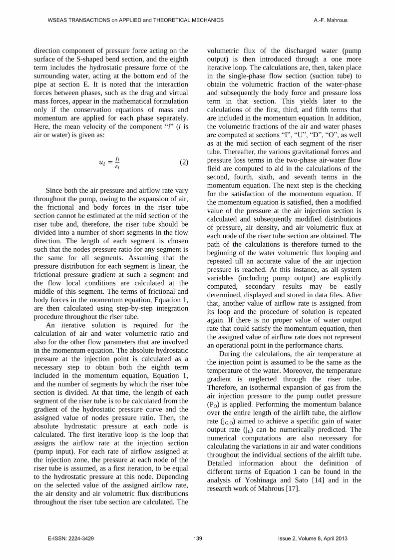
Here, the mean velocity of the component “i” (i is
air or water) is given as:
(2)
Since both the air pressure and airflow rate vary
throughout the pump, owing to the expansion of air,
the frictional and body forces in the riser tube
section cannot be estimated at the mid section of the
riser tube and, therefore, the riser tube should be
divided into a number of short segments in the flow
direction. The length of each segment is chosen
such that the nodes pressure ratio for any segment is
the same for all segments. Assuming that the
pressure distribution for each segment is linear, the
frictional pressure gradient at such a segment and
the flow local conditions are calculated at the
middle of this segment. The terms of frictional and
body forces in the momentum equation, Equation 1,
are then calculated using step-by-step integration
procedure throughout the riser tube.
An iterative solution is required for the
calculation of air and water volumetric ratio and
also for the other flow parameters that are involved
in the momentum equation. The absolute hydrostatic
pressure at the injection point is calculated as a
necessary step to obtain both the eighth term
included in the momentum equation, Equation 1,
and the number of segments by which the riser tube
section is divided. At that time, the length of each
segment of the riser tube is to be calculated from the
gradient of the hydrostatic pressure curve and the
assigned value of nodes pressure ratio. Then, the
absolute hydrostatic pressure at each node is
calculated. The first iterative loop is the loop that
assigns the airflow rate at the injection section
(pump input). For each rate of airflow assigned at
the injection zone, the pressure at each node of the
riser tube is assumed, as a first iteration, to be equal
to the hydrostatic pressure at this node. Depending
on the selected value of the assigned airflow rate,
the air density and air volumetric flux distributions
throughout the riser tube section are calculated. The
volumetric flux of the discharged water (pump
output) is then introduced through a one more
iterative loop. The calculations are, then, taken place
in the single-phase flow section (suction tube) to
obtain the volumetric fraction of the water-phase
and subsequently the body force and pressure loss
term in that section. This yields later to the
calculations of the first, third, and fifth terms that
are included in the momentum equation. In addition,
the volumetric fractions of the air and water phases
are computed at sections “I”, “U”, “D”, “O”, as well
as at the mid section of each segment of the riser
tube. Thereafter, the various gravitational forces and
pressure loss terms in the two-phase air-water flow
field are computed to aid in the calculations of the
second, fourth, sixth, and seventh terms in the
momentum equation. The next step is the checking
for the satisfaction of the momentum equation. If
the momentum equation is satisfied, then a modified
value of the pressure at the air injection section is
calculated and subsequently modified distributions
of pressure, air density, and air volumetric flux at
each node of the riser tube section are obtained. The
path of the calculations is therefore turned to the
beginning of the water volumetric flux looping and
repeated till an accurate value of the air injection
pressure is reached. At this instance, as all system
variables (including pump output) are explicitly
computed, secondary results may be easily
determined, displayed and stored in data files. After
that, another value of airflow rate is assigned from
its loop and the procedure of solution is repeated
again. If there is no proper value of water output
rate that could satisfy the momentum equation, then
the assigned value of airflow rate does not represent
an operational point in the performance charts.
During the calculations, the air temperature at
the injection point is assumed to be the same as the
temperature of the water. Moreover, the temperature
gradient is neglected through the riser tube.
Therefore, an isothermal expansion of gas from the
air injection pressure to the pump outlet pressure
(PO) is applied. Performing the momentum balance
over the entire length of the airlift tube, the airflow
rate (jG,O) aimed to achieve a specific gain of water
output rate (jL) can be numerically predicted. The
numerical computations are also necessary for
calculating the variations in air and water conditions
throughout the individual sections of the airlift tube.
Detailed information about the definition of
different terms of Equation 1 can be found in the
analysis of Yoshinaga and Sato [14] and in the
research work of Mahrous [17].
WSEAS TRANSACTIONS on APPLIED and THEORETICAL MECHANICS A.-F. Mahrous
E-ISSN: 2224-3429 139 Issue 2, Volume 8, April 2013

3 Numerical Results and Discussion
3.1 Numerical Model Validation In an attempt to verify the validity of the present
modelling approach, the predicted results obtained
by the developed numerical model were compared
with the experimental data measured by Weber and
Dedegil [18] and Yoshinaga et al. [14, 19] for
vertically straight riser tubes, and with
measurements of Fujimoto et al. [6] in case of riser
tube with local bends. The theoretical predictions
and the experimental data of the performance of
airlift pump while lifting pure water have been
compared through Fig.3, Fig.4, and Fig.5 at uniform
tube cross-sectional area and at different values of
submergence ratio (α). Figures 3, 4 and 5 show a
typical example of the water pumped rate (water
volumetric flux, jL= QL / AU, where AU is the
uniform cross sectional area of riser tube diameter
DU) as a function of air supplying rate calculated at
standard atmospheric conditions (air volumetric
flux, jGa= jG,O = QG,O / AU). For each degree of
submergence ratio, the airflow was systematically
varied and the corresponding water flow rates were
numerically predicted. As illustrated in Fig.3, for a
constant value of submergence ratio, the water flow
rate increases by increasing the airflow rate.
Depending on the degree of pump submergence,
such behaviour continues until a limiting point is
reached, where the water flow rate reaches a
maximum value. Further increase in the airflow rate
causes a decrease in the water flow rate. This
reduction in the water flow rate can be attributed to
the fact that the flow pattern in the riser tube at
higher rates of airflow tends to become annular. At
lower airflow rates, however, slug flow regime is
dominating in the airlift tube. In the bubbly-slug
flow regime, the water pumped rate is directly
proportional to the airflow rate [20]. The results for
the presented submergence ratios indicate a
common pattern of variation. It is clear that, the
submergence ratio has a strong effect on the lifting
characteristics of the airlift pump. As illustrated in
Fig.3, Fig.4, and Fig.5, the performance of airlift
pump is well predicted by the developed numerical
code over the entire range of presented submergence
ratios and in both straight and bent riser tube
configurations. The comparison between the
numerical and measured data, thus, demonstrates a
high degree of agreement that is sufficient to justify
the use of this simulation tool for parametric
predictive studies.
In the following subsection, unless otherwise
mentioned, a model airlift pump having
specifications of DU = 18 mm, S-bend test length
(LB) = 61 mm, riser length (LR) = 2.4 m, suction
length (LS) = 0.8 m, = 0.25, bend angle () = 90o,
expansion ratio () = 1, and Submergence Ratio (α )
= 70% is numerically investigated.
Fig.3: Comparison of numerical results calculated
based on present theoretical model with
experimental data by Yoshinaga et al. [14, 19].
Experimental conditions are: DU = DD=26 mm,
LR=6.74m, and LS=1.12m.
Fig.4: Comparison of numerical results calculated
based on present theoretical model with
experimental data by Weber and Dedegil [18].
Experimental conditions are: DU = DD=300mm.
LS=8m, LR=130m, α = 94%
LS=341m, LR=110m, α = 90%
Present Simulations
WSEAS TRANSACTIONS on APPLIED and THEORETICAL MECHANICS A.-F. Mahrous
E-ISSN: 2224-3429 140 Issue 2, Volume 8, April 2013

Fig.5: Comparison of numerical results calculated
based on present theoretical model with
experimental data by Fujimoto et al. [6].
Experimental conditions are: local bends on the riser
section, DU = DD = 18 mm, LR=2.4m, LS=0.8m,
LB=0.61m, and = 0.1833.
3.2 Effect of Bend Section Configuration
Fig.6 (a and b) shows the water volumetric flux
against the air volumetric flux at different degrees of
expansion ratio () of the S-bend tube section. In
this case, the S-bend tube section was set at 25% of
the -ratio and the pump was run under 70%
submergence ratio. In addition, the upstream
diameter (DU) and the bend tube straight section
length (LB) were kept at 18mm and 0.61m,
respectively. As depicted in Fig.6a, it is clear that
for reasonably low air flow rates, the water
discharge rate is not appreciably influenced by the
expansion ratio. For higher airflow rates, however,
the pump output is improved when increasing the
degree of S-bend tube expansion ratio as compared
to the case of uniform diameter S-bend tube. This
behaviour could be attributed to the fact that at low
air flow rates, bubbly flow regime dominated in the
riser tube, while at higher airflow rates, the flow
pattern tends to become annular. Increasing riser
tube diameter of the S-bend straight section helps
minimize the acceleration loss that is accompanied
by large values of air void fraction. As the degree of
S-bend tube expansion ratio increases, there would
be a corresponding increase in the water pumping
rate but with uneven incremental increase. The
incremental increase in the pump water discharge
rate is decreasing as the expansion ratio increases.
This suggests a limitation for the degree of the
expansion ratio beyond which flow separation could
take place in the riser tube.
Results in Fig.6a also illustrate that the water
pumped rate in case of model airlift pump with
higher degrees of bend tube expansion ratio
continues to increase beyond the air flow rate at the
point of maximum water pumped rate in case of
model airlift pump with local bend of uniform cross
section. Increasing the diameter of the S-bend
straight section by 75 %, for example, increases the
maximum water discharge rate by about 25% as
compared to the case with uniform bend cross
section (see Fig.6b).
(a)
(b)
Fig.6: Effects of bend expansion ratio () on water
discharge rate (a) and maximum pump discharge (b)
(LB=0.61m, DU=18 mm, α=70%, and = 0.25).
WSEAS TRANSACTIONS on APPLIED and THEORETICAL MECHANICS A.-F. Mahrous
E-ISSN: 2224-3429 141 Issue 2, Volume 8, April 2013
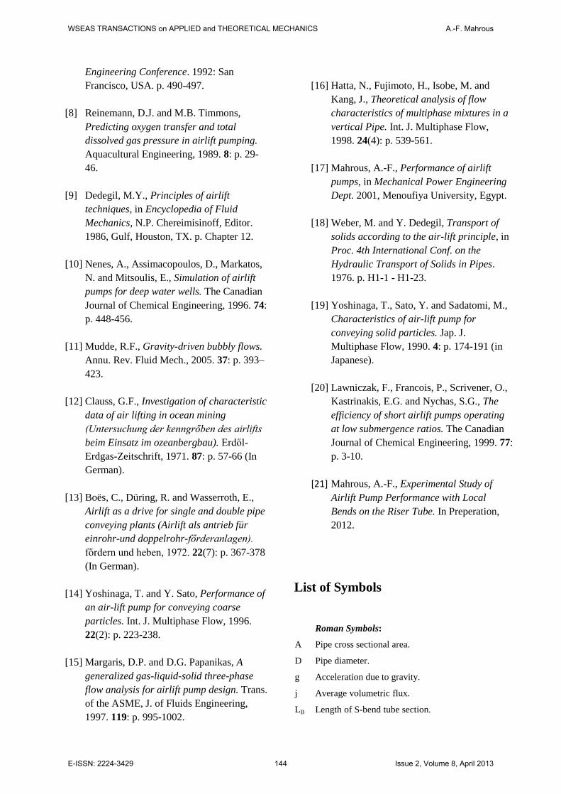
The development of air phase in the riser tube at
different degrees of S-bend ratio is shown in Fig.7
in terms of variations in the gas holdup at jGa(based
on diameter DU)=5 m/sec. For a constant value of
the expansion ratio, the gas holdup is gradually
increasing as the air rises in the riser tube. Results in
Fig.7 demonstrate that gradually enlarging the S-
bend straight section of the riser tube decreases the
volumetric fraction of the gas phase along the riser
tube and therefore reduces the acceleration loss.
Incremental reduction in the air volumetric fraction
due to bend tube expansion is high at lower degrees
of tube expansion ratio. As explained earlier,
increasing the degree of S-bend tube expansion ratio
could cause flow separation due to adverse pressure
gradient in the diffusing section.
Fig.7: Variation of gas volumetric fraction along
flow path line of the riser tube for the case of non-
uniform S-bend cross section at jGa(based on DU)=5
m/s (LB=61mm, DU=18mm, α=70%, and = 0.25).
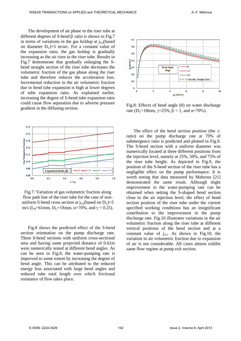
Fig.8 shows the predicted effect of the S-bend
section orientation on the pump discharge rate.
Three S-bend sections with uniform cross-sectional
area and having same projected distance of 0.61m
were numerically tested at different bend angles. As
can be seen in Fig.8, the water-pumping rate is
improved to some extent by increasing the degree of
bend angle. This can be attributed to the reduced
energy loss associated with large bend angles and
reduced tube total length over which frictional
resistance of flow takes place.
Fig.8: Effects of bend angle () on water discharge
rate (DU=18mm, =25%, = 1, and α=70%).
The effect of the bend section position (the -
ratio) on the pump discharge rate at 70% of
submergence ratio is predicted and plotted in Fig.9.
The S-bend section with a uniform diameter was
numerically located at three different positions from
the injection level, namely at 25%, 50%, and 75% of
the riser tube height. As depicted in Fig.9, the
position of the S-bend section of the riser tube has a
negligible effect on the pump performance. It is
worth noting that data measured by Mahrous [21]
demonstrated the same result. Although slight
improvement in the water-pumping rate can be
obtained when setting the S-shaped bend section
close to the air injection level, the effect of bend
section position of the riser tube under the current
specified working conditions has an insignificant
contribution to the improvement in the pump
discharge rate. Fig.10 illustrates variations in the air
volumetric fraction along the riser tube at different
vertical positions of the bend section and at a
constant value of jGa. As shown in Fig.10, the
variation in air volumetric fraction due to expansion
of air is not considerable. All cases almost exhibit
same flow regime at pump exit section.
WSEAS TRANSACTIONS on APPLIED and THEORETICAL MECHANICS A.-F. Mahrous
E-ISSN: 2224-3429 142 Issue 2, Volume 8, April 2013

Fig.9: Effects of the -ratio on the water discharge
rate (LB=0.61m, DU=DD=18mm, and α=70%).
Fig.10: Variation of gas volumetric fraction along
the riser tube at different S-bend positions where
jGa=5 m/s (LB=61mm, DU=18mm, α=70%, and =
1).
4 Conclusions The performance of airlift pumps depends mainly
on two groups of parameters. The first group is the
geometrical parameters such as pipe diameter, pump
height, design of injection system, and entrance
geometry of the lifting pipe, while the other group is
the operational parameters like the submergence
ratio, injected gas flow rate and its corresponding
pressure, and nature of lifted phase. This research
presents a numerical predictive study of the effects
of riser tube configuration on the airlift pump
performance. Changing diameter, position, and tube
orientation of riser pipe local S-bend straight tube
section of the airlift pump was numerically
investigated. The numerical model was assessed and
verified through a comparison with available
experimental data. Numerical results presented so
far showed that the airlift pump performance is
improved by gradually enlarging the straight tube
section of the S-shaped bend of the riser tube. The
results additionally proved an improvement in the
pump discharge rate when increasing the angle of
the S-bend tube section.
References
[1] Parker, G.J., The effect of foot piece design
on the performance of a small diameter
airlift pump. Int. J. Heat and Fluid Flow,
1980. 2(4): p. 245-252.
[2] Mansour, H. and M.F. Khalil, Effect of air
injection method on the performance of
airlift pump. Mansoura Eng. J., 1990.
15(2): p. 107-118.
[3] Khalil, M.F., Elshorbagy, K. A., Kassab, S.
Z. and Fahmy, R. I., Effect of air injection
method on the performance of an airlift
pump. Int. J. Heat and Fluid Flow, 1999.
20: p. 598-604.
[4] Khalil, M.F. and H. Mansour, Improvement
of the performance of an airlift pump by
means of surfactants. Mansoura Eng. J.,
1990. 15(2): p. 119-129.
[5] Mahrous, A.-F., Numerical Study of Solid
Particles-Based Airlift Pump Performance.
WSEAS Transactions on Applied and
Theoretical Mechanics, 2012. 7(3): p. 221-
230.
[6] Fujimoto, H., Murakami, S., Omura, A.,
and Takuda, H., Effect of local pipe bends
on pump performance of a small air-lift
system in transporting solid particles.
International Journal of Heat and Fluid
Flow, 2004. 25: p. 996–1005.
[7] Shimizu, Y., Tojo, C., Suzuki, M.,
Takagaki, Y. and Saito, T., A study on the
air-lift pumping system for manganese
nodule mining, in Proc. of the 2nd
International Offshore and Polar
WSEAS TRANSACTIONS on APPLIED and THEORETICAL MECHANICS A.-F. Mahrous
E-ISSN: 2224-3429 143 Issue 2, Volume 8, April 2013
Engineering Conference. 1992: San
Francisco, USA. p. 490-497.
[8] Reinemann, D.J. and M.B. Timmons,
Predicting oxygen transfer and total
dissolved gas pressure in airlift pumping.
Aquacultural Engineering, 1989. 8: p. 29-
46.
[9] Dedegil, M.Y., Principles of airlift
techniques, in Encyclopedia of Fluid
Mechanics, N.P. Chereimisinoff, Editor.
1986, Gulf, Houston, TX. p. Chapter 12.
[10] Nenes, A., Assimacopoulos, D., Markatos,
N. and Mitsoulis, E., Simulation of airlift
pumps for deep water wells. The Canadian
Journal of Chemical Engineering, 1996. 74:
p. 448-456.
[11] Mudde, R.F., Gravity-driven bubbly flows.
Annu. Rev. Fluid Mech., 2005. 37: p. 393–
423.
[12] Clauss, G.F., Investigation of characteristic
data of air lifting in ocean mining
(Untersuchung der kenngrőben des airlifts
beim Einsatz im ozeanbergbau). Erdől-
Erdgas-Zeitschrift, 1971. 87: p. 57-66 (In
German).
[13] Boës, C., Düring, R. and Wasserroth, E.,
Airlift as a drive for single and double pipe
conveying plants (Airlift als antrieb für
einrohr-und doppelrohr-főrderanlagen).
főrdern und heben, 1972. 22(7): p. 367-378
(In German).
[14] Yoshinaga, T. and Y. Sato, Performance of
an air-lift pump for conveying coarse
particles. Int. J. Multiphase Flow, 1996.
22(2): p. 223-238.
[15] Margaris, D.P. and D.G. Papanikas, A
generalized gas-liquid-solid three-phase
flow analysis for airlift pump design. Trans.
of the ASME, J. of Fluids Engineering,
1997. 119: p. 995-1002.
[16] Hatta, N., Fujimoto, H., Isobe, M. and
Kang, J., Theoretical analysis of flow
characteristics of multiphase mixtures in a
vertical Pipe. Int. J. Multiphase Flow,
1998. 24(4): p. 539-561.
[17] Mahrous, A.-F., Performance of airlift
pumps, in Mechanical Power Engineering
Dept. 2001, Menoufiya University, Egypt.
[18] Weber, M. and Y. Dedegil, Transport of
solids according to the air-lift principle, in
Proc. 4th International Conf. on the
Hydraulic Transport of Solids in Pipes.
1976. p. H1-1 - H1-23.
[19] Yoshinaga, T., Sato, Y. and Sadatomi, M.,
Characteristics of air-lift pump for
conveying solid particles. Jap. J.
Multiphase Flow, 1990. 4: p. 174-191 (in
Japanese).
[20] Lawniczak, F., Francois, P., Scrivener, O.,
Kastrinakis, E.G. and Nychas, S.G., The
efficiency of short airlift pumps operating
at low submergence ratios. The Canadian
Journal of Chemical Engineering, 1999. 77:
p. 3-10.
[21] Mahrous, A.-F., Experimental Study of
Airlift Pump Performance with Local
Bends on the Riser Tube. In Preperation,
2012.
List of Symbols
Roman Symbols:
A Pipe cross sectional area.
D Pipe diameter.
g Acceleration due to gravity.
j Average volumetric flux.
LB Length of S-bend tube section.
WSEAS TRANSACTIONS on APPLIED and THEORETICAL MECHANICS A.-F. Mahrous
E-ISSN: 2224-3429 144 Issue 2, Volume 8, April 2013

LD Riser tube length downstream of the S-bend section.
LI Submergence height.
LR Riser tube length.
LS Suction tube length.
LU Riser tube length upstream of the S-bend section.
P Pressure.
Q Volumetric flow rate.
u Velocity.
z Elevation of the mixture level in the pipe.
Greek Symbols:
Submergence ratio (LI / LR).
Expansion ratio (DD / DU).
Volumetric fraction.
Ratio (LU / LR).
Bend angle.
Density.
Shear stress.
Subscripts:
2 Two-phase air-water mixture.
a Atmospheric conditions.
B S-bend section.
D Downstream of bend.
E Pipe inlet section.
G Gas (air) phase.
i Index denotes the type of phase.
L Liquid (water) phase.
O Pipe outlet section.
s Surface.
U Upstream of bend.
WSEAS TRANSACTIONS on APPLIED and THEORETICAL MECHANICS A.-F. Mahrous
E-ISSN: 2224-3429 145 Issue 2, Volume 8, April 2013