performance suspension parts - carid · performance suspension parts. air lift performance ... rim...
TRANSCRIPT

PERFORMANCE SUSPENSION PARTS

Air Lift Performance
IntroductionThe purpose of this publication is to assist with the installation, maintenance and troubleshooting of this Audi A6 C5 Performance kit.
It is important to read and understand the entire installation guide before beginning installation or performing any maintenance, service or repair . The information includes a hardware list, step-by-step installation information, maintenance tips, safety information and a troubleshooting guide .
NOTATION EXPLANATIONHazard notations appear in various locations in this publication . Information which is highlighted by one of these notations must be observed to help minimize risk of personal injury or possible improper installation which may render the vehicle unsafe . Notes are used to help emphasize areas of procedural importance and provide helpful suggestions . The following definitions explain the use of these notations as they appear throughout this guide.
INDICATES IMMEDIATE HAZARDS WHICH WILL RESULT IN SEVERE PERSONAL INJURY OR DEATH.
INDICATES HAZARDS OR UNSAFE PRACTICES WHICH COULD RESULT IN SEVERE PERSONAL INJURY OR DEATH.
INDICATES HAZARDS OR UNSAFE PRACTICES WHICH COULD RESULT IN DAMAGE TO THE MACHINE OR MINOR PERSONAL INJURY.
Indicates a procedure, practice or hint which is important to highlight.
IMPORTANT SAFETY NOTICESThe installation of this kit does not alter the Gross Vehicle Weight Rating (GVWR) or payload of the vehicle . Check your vehicle’s owner’s manual and do not exceed the maximum load listed for your vehicle .
Gross Vehicle Weight Rating: The maximum allowable weight of the fully loaded vehicle (including passengers and cargo) . This number — along with other weight limits, as well as tire, rim size and inflation pressure data — is shown on the vehicle’s Safety Compliance Certification Label.
Payload: The combined, maximum allowable weight of cargo and passengers that the vehicle is designed to carry. Payload is GVWR minus the Base Curb Weight.
DO NOT INFLATE AIR SPRINGS WHILE OFF OF THE VEHICLE. DAMAGE TO ASSEMBLY MAY RESULT AND VOID WARRANTY.
DO NOT WELD TO, OR MODIFY PERFORMANCE STRUTS/SHOCKS IN ANY WAY. DAMAGE TO UNIT MAY OCCUR AND WILL VOID WARRANTY.
DANGER
NOTE
WARNING
CAUTION
WARNING
CAUTION

Air Lift Performance
HARDWARE LIST
Item Part # Description . . . . . . . . . . . . . . . . . . . . . . . . . . . . . . . . . . Qty A 35204 Shock, Audi C5 Front . . . . . . . . . . . . . . . . . . . . . . . . . . . . .2 B 20997 Leader Hose, 1/4” ID . . . . . . . . . . . . . . . . . . . . . . . . . . . . . .2 C 21810 Union, 1/4”FNPT X 1/4” PTC, DOT . . . . . . .2 D 21987 Union, 1/4”FNPT X 3/8” PTC, DOT . . . . . . . .2 E Shock Adjuster . . . . . . . . . . . . . . . . . . . . . . . . . . . . . . . . . . . . . . .2 F Spanner Wrench . . . . . . . . . . . . . . . . . . . . . . . . . . . . . . . . . . . .1
Installation Diagram
fig. 1
B
A
C or D
F
Air Lift Performance
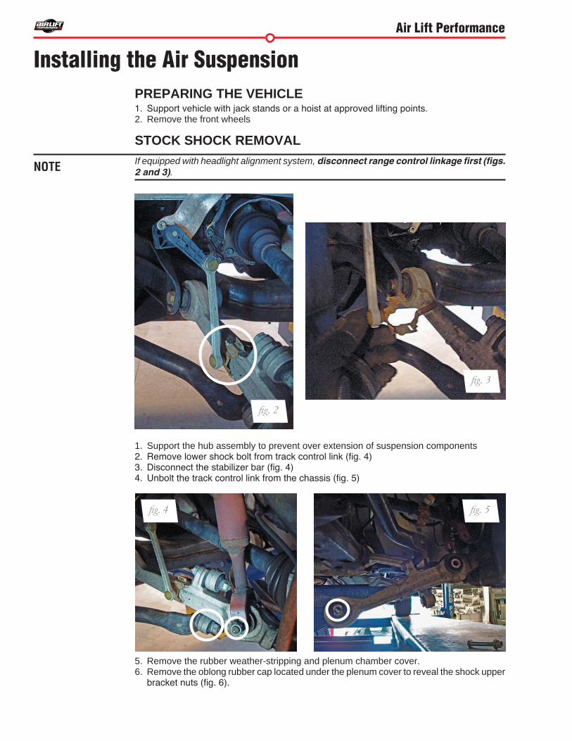
PREPARING THE VEHICLE1. Support vehicle with jack stands or a hoist at approved lifting points. 2 . Remove the front wheels
STOCK SHOCK REMOVALIf equipped with headlight alignment system, disconnect range control linkage first (figs. 2 and 3).
1 . Support the hub assembly to prevent over extension of suspension components2. Remove lower shock bolt from track control link (fig. 4)3. Disconnect the stabilizer bar (fig. 4)4. Unbolt the track control link from the chassis (fig. 5)
5 . Remove the rubber weather-stripping and plenum chamber cover . 6 . Remove the oblong rubber cap located under the plenum cover to reveal the shock upper
bracket nuts (fig. 6).
Installing the Air Suspension
NOTE
fig. 3
fig. 4 fig. 5
fig. 2

Air Lift Performance
7. Unthread both upper nuts from the bracket. Remove the shock assembly from the vehicle (fig. 7).
8 . If the upper control arm bolt heads face toward the outside of the bracket remove the bolts and flip them so the head of the bolt will face the air spring (fig. 8). This is done to gain air spring clearance and prevent wear of the air spring .
FAILURE TO DO THIS MAY RESULT IN A PREMATURE FAILURE OF THE AIR SPRING AND WILL NOT BE COVERED UNDER WARRANTY. TIGHTEN THE BOLTS DOWN JUST ENOUGH THAT THE BUSHING CAN STILL ROTATE AROUND THE BOLT.
CAUTION
fig. 7
fig. 8
BOLT HEAD FACING AIR SPRING
fig. 6

Air Lift Performance
MODIFICATIONS FOR AIR SUSPENSION
1. Center punch and drill a 3/8” hole though the center of the suspension shock dome. This hole will be used as an access port for damping adjustments (fig. 8).
INSTALLING THE AIR SUSPENSION
1. Begin by installing the leader line into the air spring. Wrap the threads of the leader hose with Teflon tape or thread sealant. Tighten the appropriate fitting to the airline 1 ¾ turns beyond hand tight. Tighten the leader line into the air spring 1 ¾ turns beyond hand tight (fig. 9).
2 . Insert the new assembly and attach the upper bracket in place with the two nuts previously removed (fig. 6).
3. Loosely install the clevis bolt into the lower control arm (fig. 10). Also, loosely reinstall the track link to chassis bolt . Loosely reattach the sway bar . Reinstall the headlight alignment bracket if equipped . Do not tighten these at this time .
fig. 8
fig. 10
fig. 9

Air Lift Performance
Torque Specifications
Location Nm lb-ft
Shock upper bracket to or upper bracket 20 15
Upper control arms to bracket 50Nm + 90° 37 lb-ft + 90°
Track control link to shock clevis 90 66
Track control link to subframe 80 + 90˚ 59 lb-ft + 90˚
Guide link to subframe 90Nm + 90° 66 lb-ft + 90°
End link to track control link 40 30
End link to sway bar 100 74
Wheels 120 89
4. Fully compress the suspension using a jack. With the suspension compressed, review the best routing for the leader hose that is clear of all suspension components and axle . Routing should also allow for the suspension to extend without kinking the line or rubbing on other components . Check clearances to all other components .
5. With the suspension fully compressed, take a measurement from the fender to some reference point – typically the center of the axle . Record this measurement as Max Compression .
6 . Cycle the suspension to Max Extension and record the measurement from the same reference points .
7. Take the difference between the two numbers and divide by two. Add that value to the original Max Compression number . Set the suspension to this point . This position will give 50% stroke in either direction and is a starting point for ride height (fig. 11).
8. With the suspension at this position, torque the lower shock bolt and upper and lower control arm bolts to manufacturer’s specifications (Table 1).
Formula for calculating ride height (fig. 11):
fig. 11
ME- MC
X
Step 1:
+ MC
Z
YStep 3:
Z = DESIGN HEIGHT
Answer:
X = Y 2
Step 2:
Table 1

Air Lift Performance
DAMPING ADJUSTMENT The struts in this kit have 30 settings, or “clicks”, of adjustable compression and rebound damping characteristics . Damping is changed through the strut rod using the supplied adjuster (figs. 12 & 13) or a 3mm allen wrench.
Turn the adjuster clockwise and the damping settings are hardened. Turn the adjuster counterclockwise and the damping is softened .
Each shock is preset to “-15 clicks”. This means that the shock is adjusted 15 clicks away from full stiff . Counting down from full stiff is the preferred method of keeping track of, or setting, damping. This setting was developed on a 2001 Audi A6 V8 quattro and may need to be adjusted to different vehicles and driving characteristics.
ALIGNING THE VEHICLE1. Using the control system, set the vehicle height to the new custom ride height.
2 . If the custom ride height is lower than stock, we recommend loosening all pivot points (bolts, nuts) on any control arm, strut arm or radius rod that contains bushings. Once they have been loosened, re-torque to stock specifications.
It may be necessary to cycle the suspension to loosen the bushing up from its mount. This will help re-orient the bushing at its new position based on the custom ride height.
fig. 12 fig. 13
NOTE

Air Lift Performance
ADJUSTING EXTENDED OR DROP HEIGHT USING LOWER MOUNTYour struts have been pre-set at the factory to provide maximum drop height while maintaining adequate tire clearance to the air spring . If you wish to gain more extended height (lift), which is the same as reducing drop height, or want to lower the chassis further and there is still adjustment available at the lower mount, please use the following procedure:
1. Support the vehicle with jack stands or a hoist at approved lifting points.
2 . Remove the wheel .
3. Using the supplied spanner wrench, loosen the lower locking collar (fig. 14).
4. Deflate the air spring to 0 PSI on the corner you are adjusting.
5 . Disconnect lower mount from suspension .
6 . Spin the lower mount to the desired location .
Not all models will have further drop height available.
7. Re-install lower mount to suspension and torque fasteners.
8. Tighten the lower locking collar to the lower mount using significant force.
WHEN ADJUSTING HEIGHT UPWARDS, MAKE SURE THAT THE STRUT BODY ENGAGES ALL THE THREADS OF THE LOWER MOUNT (FIG. 15). WHEN ADJUSTING DOWNWARDS, MAKE SURE THERE IS ADEQUATE AIR SPRING CLEARANCE TO THE TIRE/WHEEL ASSEMBLY. CLEARANCE MUST BE CHECKED WITH SYSTEM FULLY DEFLATED AS WELL AS FULLY INFLATED TO ENSURE THAT NO RUBBING
fig. 14
NOTE
CAUTION
Air Lift Performance
CAUTION
FOR STRUTS: FOR SHOCKS:
Thread MUST be showing in window.
OK, no threads showing.
Not OK, threadsare showing.
fig. 15
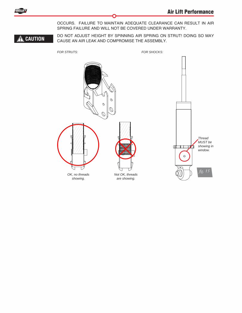
OCCURS. FAILURE TO MAINTAIN ADEQUATE CLEARANCE CAN RESULT IN AIR SPRING FAILURE AND WILL NOT BE COVERED UNDER WARRANTY.
DO NOT ADJUST HEIGHT BY SPINNING AIR SPRING ON STRUT! DOING SO MAY CAUSE AN AIR LEAK AND COMPROMISE THE ASSEMBLY.


Air Lift Performance
IntroductionThe purpose of this publication is to assist with the installation, maintenance and troubleshooting of this Audi A6 C5 Performance kit .
It is important to read and understand the entire installation guide before beginning installation or performing any maintenance, service or repair . The information includes a hardware list, step-by-step installation information, maintenance tips, safety information and a troubleshooting guide .
NOTATION EXPLANATIONHazard notations appear in various locations in this publication . Information which is highlighted by one of these notations must be observed to help minimize risk of personal injury or possible improper installation which may render the vehicle unsafe . Notes are used to help emphasize areas of procedural importance and provide helpful suggestions . The following definitions explain the use of these notations as they appear throughout this guide.
INDICATES IMMEDIATE HAZARDS WHICH WILL RESULT IN SEVERE PERSONAL INJURY OR DEATH .
INDICATES HAZARDS OR UNSAFE PRACTICES WHICH COULD RESULT IN SEVERE PERSONAL INJURY OR DEATH .
INDICATES HAZARDS OR UNSAFE PRACTICES WHICH COULD RESULT IN DAMAGE TO THE MACHINE OR MINOR PERSONAL INJURY .
Indicates a procedure, practice or hint which is important to highlight.
IMPORTANT SAFETY NOTICESThe installation of this kit does not alter the Gross Vehicle Weight Rating (GVWR) or payload of the vehicle . Check your vehicle’s owner’s manual and do not exceed the maximum load listed for your vehicle .
Gross Vehicle Weight Rating: The maximum allowable weight of the fully loaded vehicle (including passengers and cargo) . This number — along with other weight limits, as well as tire, rim size and inflation pressure data — is shown on the vehicle’s Safety Compliance Certification Label.
Payload: The combined, maximum allowable weight of cargo and passengers that the vehicle is designed to carry . Payload is GVWR minus the Base Curb Weight .
DO NOT INFLATE AIR SPRINGS WHILE OFF OF THE VEHICLE . DAMAGE TO ASSEMBLY MAY RESULT AND VOID WARRANTY .
DO NOT WELD TO, OR MODIFY PERFORMANCE STRUTS/SHOCKS IN ANY WAY . DAMAGE TO UNIT MAY OCCUR AND WILL VOID WARRANTY .
DANGER
NOTE
WARNING
CAUTION
WARNING
CAUTION

Air Lift Performance
HARDWARE LIST
Item Part # Description . . . . . . . . . . . . . . . . . . . . . . . . . . . . . . . .Qty A 35205 Shock, Rear Audi A6 C5 . . . . . . . . . . . . . . . . . . . . . 1 B 20997 Leader Hose, 1/4” ID . . . . . . . . . . . . . . . . . . . . . . . . . . 1 C 21810 Union, 1/4”FNPT X 1/4” PTC, DOT . . . 1 D 21987 Union, 1/4”FNPT X 3/8” PTC, DOT . . . . 1 E Spanner Wrench . . . . . . . . . . . . . . . . . . . . . . . . . . . . . . . . . 1
Installation Diagram
fig. 1
A
C or D
B
E

Air Lift Performance
Installing the Air SuspensionPREPARING THE VEHICLE1 . Elevate and support the vehicle with a hoist or jack stands .
2 . Remove the rear tire and support the hub assembly (fig. 2).
REMOVING THE REAR SHOCK1 . Disconnect the stabilizer bar link from the control arm (figs. 3 and 4).
2 . Loosen all control arm attachment bolts (figs. 3 and 4). Remove the shock eye and headlight alignment bracket bolts (fig. 5).
fig. 5
fig. 4fig. 3
fig. 2

Air Lift Performance
fig. 9
3 . Remove the upper control arm to spindle connecting bolt (fig. 6).
4 . Unbolt the shock upper bracket from the chassis (fig. 7).
5 . Press down on the hub assembly far enough to pull the shock upper mount out of the chassis cavity . Care must be taken to not over-extent and damage the rubber brake lines. Remove the assembly from the vehicle (fig. 9).
fig. 6
fig. 7

Air Lift Performance
PREPARING THE AIR SUSPENSION1 . Begin by installing the air fitting to the braided leader line. Coat the threads of the leader
line with thread sealant. Tighten the fitting 1 ¾ turns beyond hand tight. With thread sealant at the other end of the leader line, thread the leader line into the airspring, tightening 1 ¾ turns beyond hand tight.
INSTALLING THE AIR SUSPENSION1 . Insert and attach the shock assembly to the chassis mounting holes with the leader line
positioned away from the wheel (fig. 10).
2 . Lift the hub assembly aligning the shock eye mount with the location hole . Install the shock eye bolt through the control arm and loosely assemble the nut (fig. 11).
fig. 8
fig. 11
fig. 10
Air Lift Performance
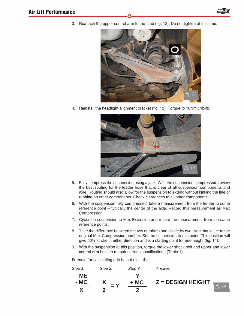
3 . Reattach the upper control arm to the hub (fig. 12). Do not tighten at this time.
4 . Reinstall the headlight alignment bracket (fig. 13). Torque to 10Nm (7lb-ft).
5 . Fully compress the suspension using a jack . With the suspension compressed, review the best routing for the leader hose that is clear of all suspension components and axle . Routing should also allow for the suspension to extend without kinking the line or rubbing on other components . Check clearances to all other components .
6 . With the suspension fully compressed, take a measurement from the fender to some reference point – typically the center of the axle . Record this measurement as Max Compression .
7 . Cycle the suspension to Max Extension and record the measurement from the same reference points .
8 . Take the difference between the two numbers and divide by two . Add that value to the original Max Compression number . Set the suspension to this point . This position will give 50% stroke in either direction and is a starting point for ride height (fig. 14).
9. With the suspension at this position, torque the lower shock bolt and upper and lower control arm bolts to manufacturer’s specifications (Table 1).
Formula for calculating ride height (fig. 14):
fig. 14
ME- MC
X
Step 1:
+ MCZ
YStep 3:
Z = DESIGN HEIGHT
Answer:
X = Y 2
Step 2:
fig. 13
fig. 12
Air Lift Performance
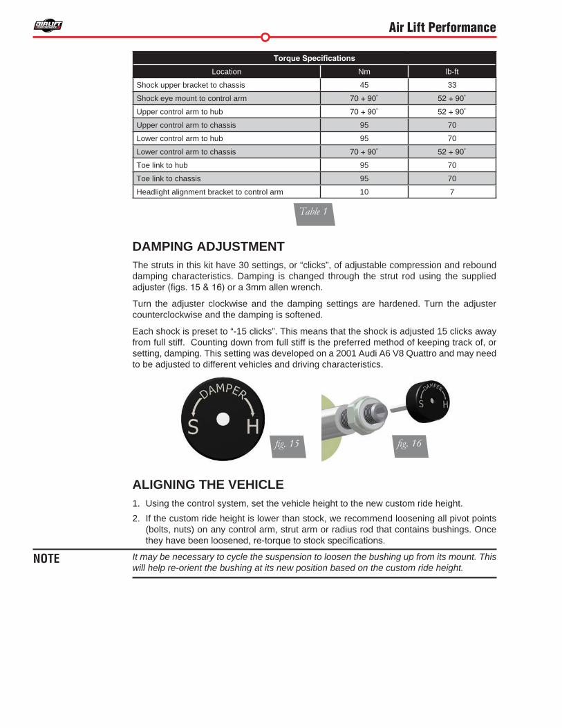
DAMPING ADJUSTMENT The struts in this kit have 30 settings, or “clicks”, of adjustable compression and rebound damping characteristics . Damping is changed through the strut rod using the supplied adjuster (figs. 15 & 16) or a 3mm allen wrench.
Turn the adjuster clockwise and the damping settings are hardened . Turn the adjuster counterclockwise and the damping is softened .
Each shock is preset to “-15 clicks” . This means that the shock is adjusted 15 clicks away from full stiff . Counting down from full stiff is the preferred method of keeping track of, or setting, damping . This setting was developed on a 2001 Audi A6 V8 Quattro and may need to be adjusted to different vehicles and driving characteristics .
ALIGNING THE VEHICLE1 . Using the control system, set the vehicle height to the new custom ride height .
2 . If the custom ride height is lower than stock, we recommend loosening all pivot points (bolts, nuts) on any control arm, strut arm or radius rod that contains bushings . Once they have been loosened, re-torque to stock specifications.
It may be necessary to cycle the suspension to loosen the bushing up from its mount. This will help re-orient the bushing at its new position based on the custom ride height.
fig. 15 fig. 16
NOTE
Torque Specifications
Location Nm lb-ft
Shock upper bracket to chassis 45 33
Shock eye mount to control arm 70 + 90˚ 52 + 90˚
Upper control arm to hub 70 + 90˚ 52 + 90˚
Upper control arm to chassis 95 70
Lower control arm to hub 95 70
Lower control arm to chassis 70 + 90˚ 52 + 90˚
Toe link to hub 95 70
Toe link to chassis 95 70
Headlight alignment bracket to control arm 10 7
Table 1

Air Lift Performance
ADJUSTING EXTENDED OR DROP HEIGHT USING LOWER MOUNTYour struts have been pre-set at the factory to provide maximum drop height while maintaining adequate tire clearance to the air spring. If you wish to gain more extended height (lift), which is the same as reducing drop height, or want to lower the chassis further and there is still adjustment available at the lower mount, please use the following procedure:
1 . Support the vehicle with jack stands or a hoist at approved lifting points .
2 . Remove the wheel .
3. Using the supplied spanner wrench, loosen the lower locking collar (fig. 17).
4. Deflate the air spring to 0 PSI on the corner you are adjusting.
5 . Disconnect lower mount from suspension .
6 . Spin the lower mount to the desired location .
Not all models will have further drop height available.
7. Re-install lower mount to suspension and torque fasteners.
8. Tighten the lower locking collar to the lower mount using significant force.
WHEN ADJUSTING HEIGHT UPWARDS, MAKE SURE THAT THE STRUT BODY ENGAGES ALL THE THREADS OF THE LOWER MOUNT (FIG . 18) . WHEN ADJUSTING DOWNWARDS, MAKE SURE THERE IS ADEQUATE AIR SPRING CLEARANCE TO THE TIRE/WHEEL ASSEMBLY . CLEARANCE MUST BE CHECKED WITH SYSTEM FULLY DEFLATED AS WELL AS FULLY INFLATED TO ENSURE THAT NO RUBBING
fig. 17
NOTE
CAUTION

Air Lift Performance
CAUTION
FOR STRUTS: FOR SHOCKS:
Thread MUST be showing in window.
OK, no threads showing.
Not OK, threadsare showing.
fig. 18
OCCURS . FAILURE TO MAINTAIN ADEQUATE CLEARANCE CAN RESULT IN AIR SPRING FAILURE AND WILL NOT BE COVERED UNDER WARRANTY .
DO NOT ADJUST HEIGHT BY SPINNING AIR SPRING ON STRUT! DOING SO MAY CAUSE AN AIR LEAK AND COMPROMISE THE ASSEMBLY .

™ Kit 27666Manual Air Management System
For maximum effectiveness and safety, please read these instructions completely before proceeding with installation.
Failure to read these instructions can result in an incorrect installation.
INSTALLATION GUIDE
Air Lift PERFORMANCE

Air Lift Performance
IntroductionThe purpose of this publication is to assist with the installation, maintenance and troubleshooting of the Air Management System.
It is important to read and understand the entire installation guide before beginning installation or performing any maintenance, service or repair. The information here includes a hardware list, tool list, step-by-step installation information, maintenance guidelines and troubleshooting guide.
IMPORTANT SAFETY NOTICEThe installation of this kit does not alter the Gross Vehicle Weight Rating (GVWR) or payload of the vehicle. Check your vehicle’s owner’s manual and do not exceed the maximum load listed for your vehicle.
Gross Vehicle Weight Rating: The maximum allowable weight of the fully loaded vehicle (including passengers and cargo). This number — along with other weight limits, as well as tire, rim size and inflation pressure data — is shown on the vehicle’s Safety Compliance Certification Label.
Payload: The combined, maximum allowable weight of cargo and passengers that the vehicle is designed to carry. Payload is GVWR minus the Base Curb Weight.
NOTATION EXPLANATIONHazard notations appear in various locations in this publication. Information which is highlighted by one of these notations must be observed to help minimize risk of personal injury or possible improper installation which may render the vehicle unsafe. Notes are used to help emphasize areas of procedural importance and provide helpful suggestions. The following definitions explain the use of these notations as they appear throughout this guide.
INDICATES IMMEDIATE HAZARDS WHICH WILL RESULT IN SEVERE PERSONAL INJURY OR DEATH.
INDICATES HAZARDS OR UNSAFE PRACTICES WHICH COULD RESULT IN SEVERE PERSONAL INJURY OR DEATH.
INDICATES HAZARDS OR UNSAFE PRACTICES WHICH COULD RESULT IN DAMAGE TO THE MACHINE OR MINOR PERSONAL INJURY.
Indicates a procedure, practice or hint which is important to highlight.
DANGER
NOTE
WARNING
CAUTION

Air Lift Performance
Hardware ListItem Part # Description Quantity
A 16380 Viair 380C Compressor 1B 11955 4 Gallon Aluminum Air Tank 1C 26228 Dual Needle Gauge 2D 21703 Paddle Switch 4E 11031 Paddle Switch Mounting Bracket 1F 20946 1/4" Airline 80'G 10530 Air Line Cutter 1H 24575 145 - 175 PSI Pressure Switch 1
Paddle Switch Mounting Bracket HardwareI 17434 #8 x 3/4" Stainless Steel Screw 4
Tank Mounting HardwareJ 17188 3/8"-16 x 1.25" Grade 5 Bolt 4K 18444 3/8" Flat Washer 8L 18435 3/8"-16 Nyloc Nut 4
Tank FittingsM 21737 3/8" Pipe Plug 1N 21738 1/4" FNPT x 3/8" MNPT Bushing 1O 21779 1/4" NPT x 1/4" Tube Elbow 2P 21610 1/8" FNPT x 1/4"MNPT Bushing 1Q 21633 Inflation Valve 1R 23586 Thread Sealant 1
Item Part # Description QuantityElectrical
S 24782 30/50A Relay 1T 24608 10 Gauge Red Wire 15'U 24643 16 Gauge Red Wire 20'V 24644 16 Gauge Black Wire 10'W 24537 Quick Splice 3X 24568 18 Gauge Ring Terminal 2Y 24594 Blue Female Spade Terminal 9Z 24748 12 Gauge Ring Terminal 3/8" ID 1
AA 24542 Fuse Tap 1BB 24561 Mini Fuse Adapter 1CC 24649 Yellow Butt Connector 1DD 24595 Yellow Female Spade Terminal 2EE 17263 1/4" x 1" Self Threading Screw 1FF 24539 Fuse Holder 1GG 24547 30A Spade Fuse 1HH 17132 1/2" Self Threading Screw 2
Gauge and Paddle Switch FittingsII 21838 1/4" Union Tee 4JJ 21842 1/4" Y Tee 3
NPT ASSEMBLY INSTRUCTIONS1. Inspect the port and fitting ensuring both are free of contaminants and excessive burrs
and nicks.2. Apply a stripe of liquid pipe sealant around the male threads leaving the first two threads
uncovered.3. Screw finger tight into the port.4. Wrench tighten the fitting to the correct turns past finger tight position (see table 1).
NEVER BACK OFF AN INSTALLED PIPE FITTING TO ACHIEVE PROPER ALIGNMENT. LOOSENING INSTALLED PIPE FITTINGS WILL CORRUPT THE SEAL AND CONTRIBUTE TO LEAKAGE AND FAILURE.
CAUTION
Torque Specifications
Fitting Size Turns Past Finger Tight
Torque lb/ft
1/8” NPT 1.5 - 3.0 12
1/4” NPT 1.5 - 3.0 25
3/8” NPT 1.5 - 3.0 40
1/2” NPT 1.5 - 3.0 54
3/4” NPT 1.5 - 3.0 78
1” NPT 1 - 2.5 112
1 1/4” NPT 1 - 2.5 154
1 1/2” NPT 1 - 2.5 211
2” NPT 1 - 2.5 300
Table 1

Air Lift Performance
Compressor Tank Pressure
Viair Air Lift P/N Max. Tank Pressure
380C 16380 175
400C 16400 150
444C 16444 175
450C 16450 150
Installing the Air Management SystemINSTALL COMPONENTSFor a complete schematic, please see fig. 1. (pages 8 – 9)
Layout1. Plan component location first. 2. Prior to mounting components, check to make sure:
• the compressor leader hose will reach the tank.• the plumbing will route cleanly through the vehicle.
Be sure to install all components as far as possible from any heat sources. Plan and prepare wiring and plumbing routing thru the vehicle. Eliminate all sharp edges that could chafe. Use grommets when passing through compartment walls.
Prepare and install the compressor1. Prepare the compressor intake. If inside the vehicle, attach filter to port on end of
compressor (fig. 1). If the compressor is located outside the vehicle, snorkel inlet filter to a dry location inside vehicle using components supplied with the compressor.
2. Center punch and drill four holes using the template on page 15.3. Attach using the hardware supplied with the compressor.
Air compressors ingest moisture and will deposit water in the tank. Tanks must be regularly purged to eliminate the possibility of water freezing inside the system or causing corrosion. Be sure to provide easy access to drain/fill valve (preferably outside the vehicle). The system does not include moisture separators or water traps, and does require periodic tank moisture drain. If using an engine driven compressor, proper oil and water filtration must be added as these compressors will contaminate the air suspension system. Water traps are available and sold separately through Air Lift Performance, part numbers: 21011 (1/4”), 21012 (3/8”), 21013 (1/2”).
NOTE
NOTE
NOTE
HELPFUL TIPS: AIR LINE AND FITTINGS1. Minimum hose bend radius
• 1/4” hose = 1” hose bend radius.2. Hose to fitting
• No side loading on fitting from hose.• Hose straight for 1” before bending.
3. Hose cutting• Cut hose perpendicular to hose length.• Inspect hose for scratches that run lengthwise on hose prior to insertion.• Use proper hose cutter, cigar cutter, or razor on flat surface.
4. DOT/SAEJ844 air brake hose data• Maximum working pressure of 175 PSI.• Not to be used for frame (body) to un-sprung mass connection, use a braided leader
hose for this moving connection.
Table 2

Air Lift Performance
NOTE
Tank pre-assembly (see fig. 1)
1. Determine tank location and orientation prior to installing fittings.2. Apply thread sealant as necessary to all fittings.3. Install the drain/fill PTC fitting in the lower most tank threaded port.4. Choose a tank threaded port for the compressor fitting.5. Choose the highest tank threaded port for air line supply. 6. Plug any remaining tank ports with hex plugs.
Tank install (see fig. 1)
1. Using the tank feet as a template, drill holes for hardware assembly.2. Attach the tank using the supplied hardware.3. Cut an appropriate length of hose from the manifold port T, to the PTC fitting on the tank.4. Route the drain/fill air line with a schrader valve (preferably outside the vehicle).
When cutting plastic air line, only use a standard hose cutter like (Air Lift part number 10530) or razorblade. Cut all hose ends square and as smoothly as possible. See hose cutting tips
MOUNTING THE SWITCH PANELRefer to the switch panel template on page 13.
1. Find a location to mount the paddle switch mounting bracket (E).2. Snap all four paddle switches (D) into the paddle switch mounting bracket (E) so the
DEL is toward the top.
You may select different locations for the paddle switches. The paddle switches do not need to be used with the supplied paddle switch mounting bracket.
3. Cut six pieces of air line (F) the same length (approximately 3”-6”).4. Push four of these pieces onto the “SUP” port of the switch. Attach two Y fittings (JJ)
to the air lines.5. Push the other two pieces of line into the Y fittings (JJ).6. Attach the last Y fitting (JJ) to the air lines.7. Mount the paddle switch mounting bracket (E) with four screws (I).
ATTACHING THE AIR LINESWHEN CUTTING OR TRIMMING THE AIR LINE, USE AN AIR LINE CUTTER (G), A RAZOR BLADE OR A SHARP KNIFE. A CLEAN, SQUARE CUT WILL ENSURE AGAINST LEAKS. DO NOT USE WIRE CUTTERS OR SCISSORS TO CUT THE AIR LINE. THESE TOOLS MAY FLATTEN OR CRIMP THE AIR LINE, CAUSING IT TO LEAK.1. Run a length of air line (F) from the air fitting on the compressor to the end of the switch
cluster.2. Run a length of air line from the remaining air fittings on the switch to its respective air
spring.3. Repeat step 2 for the remaining air fittings and air springs.4. Use a tee and connect into each one of the air spring lines to connect to it’s respective
gauge port.5. Test and make sure that the switches operate the appropriate air springs.
NOTE
CAUTION

Air Lift Performance
fig. 1
Installation DiagramInside View ofConnector (W)Inside View ofConnector (W)
Air Bags are for Reference OnlyNot included with air management system.
W
Power(Red)
Splice intokeyed on
ignition wire.
Splice intokeyed on
ignition wire.U
HH
GroundGround
DEL
SUP
E
JJ
II
II
II
II
VC
Y
V
D
I
W
W
X
F
A
HH
X
U30 AMP30 AMP
Existing Fuse
CC CCFF
AA or BBGGDD
Attach filter
GroundGround
N
L
J
KJ
L
K
O
F
M
DD
H OPB
Q
W
Refer to electrical schematic on page 12.
NOTE: Air Lift recommends using a hose cutting tool to ensure a proper cut.If a hose connection has been disconnected the hose must be trimmed 1/2” back to provide for a leak free seal.
GroundGround
Splice intokeyed onignition wire.
Splice intokeyed onignition wire.
Connect to battery

Air Lift Performance
Inside View ofConnector (W)Inside View ofConnector (W)
Air Bags are for Reference OnlyNot included with air management system.
W
Power(Red)
Splice intokeyed on
ignition wire.
Splice intokeyed on
ignition wire.U
HH
GroundGround
DEL
SUP
E
JJ
II
II
II
II
VC
Y
V
D
I
W
W
X
F
A
HH
X
U30 AMP30 AMP
Existing Fuse
CC CCFF
AA or BBGGDD
Attach filter
GroundGround
N
L
J
KJ
L
K
O
F
M
DD
H OPB
Q
W
Refer to electrical schematic on page 12.
NOTE: Air Lift recommends using a hose cutting tool to ensure a proper cut.If a hose connection has been disconnected the hose must be trimmed 1/2” back to provide for a leak free seal.
GroundGround
Splice intokeyed onignition wire.
Splice intokeyed onignition wire.
Connect to battery
.

Air Lift Performance
Electrical Schematic
fig. 3

13MN-726
Air Lift Performance
Paddle Switch Mounting Bracket Template

15MN-726
Air Lift Performance
6.69”
3.31”
HOLE PATTERN FOR BOTTOM OF 16380 COMPRESSOR
16380 Compressor Template