permanent magnet brushless dc motors ppt
TRANSCRIPT

PERMANENT MAGNET BRUSHLESS DC MOTORS
Prepared by
S.RathinamalaAssistant Professor/ EEE
KIT-KalaignarKarunanidhi Institute of Technology

PERMANENT MAGNET BRUSHLESS DC MOTORS
• It is a brushless dc motor. • It has a PM rotor type.• Why we are choosing PMBLDC Motor• Comparison between conventional dc motor
& PMBLDC Moto

Comparison between conventional dc motor & PMBLDC Motor


Construction of PMBLDC motor
• It consist of two parts mainly stator & rotor.• Stator is made up of silicon steel stampings
with slots. • The slots are accomodated armature windings. • This winding is wound with specified no.of
poles.(even number). • This winding connected a dc supply through a
power electronic switching circuits.

Construction of PMBLDC motor
• Rotor accomodates PM. • The rotor shaft carries a rotor position sensor. • Sensor provides information about the
position of the shaft. • This shaft position signal send to electronic
commutator.

advantages
• There is no mechanical commutator, so that size become very small.
• Speed can be easily controlled. • Regenerative braking is possible.

Applications
• Automotive application. • Textile and industries. • Computer and robotics. • Small appliances such as fans, mixers etc

Commutation in DC motors
(1) Mechanical commutator. (2) Electronic commutator. • Construction of Mechanical commutator • Commutator is made up of specially designed
commutator segments,made of copper. • These segments are insulated from each other
by a thin layer of mica. • It forms a cylindrical shape.

Mechanical commutator

Mechanical commutator
• It consist of 2 pole machine with 12 commutator segments.
• Carbon brush A contacts with CS 1 and brush B contacts with CS 7.
• When a dc supply is connected across A & B, a dc current passes through A-CS1-tapping1- tapping 7-CS 7 and through B.
• The current has 2 parallel path in the armature winding. • Parallel path 1= 1-2-3-4-5-6-7 • Parallel path 2=1-12-11-
10-9-8-7

Mechanical commutator
• The current crossing through the armature conductor setup an mmf along the axis A and B
• The commutator rotates along the clockwise direction, now the brush A makes contact with CS2 and brush B with CS 8.
• Now there are two parallel path 1 is 2-8 & parallel path 2 is 2-1-12-11-10-9-8.
• Function of commutator and bush arrangement is to setup an armature mmf whose axis is always in quadrature with the main field mmf irrespective of the speed of rotation of the motor.
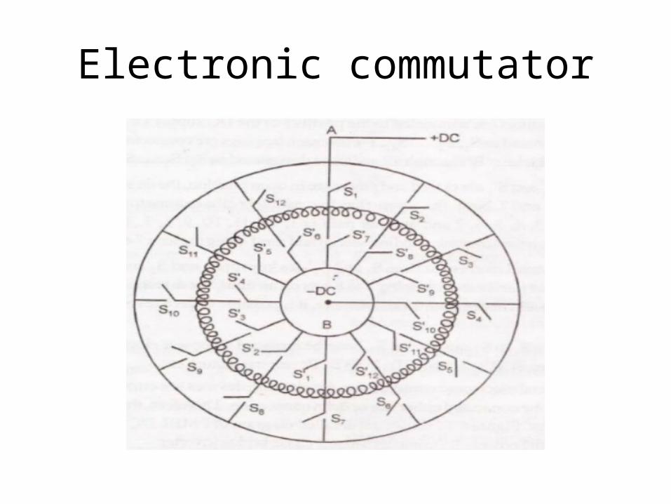
Electronic commutator

Electronic commutation

Electronic commutation
Step 1: S1 & S1’ are closed. other switches are open current has 2 parallel path in armature winding. Parallel path 1 =1-2-3-4-5-6-7
Parallel path 2 =1-12-11-10-9-8-7 These current setup in the armature mmf.
Step 2: S1 & S1’ are opened,S2 & S2’ are closed Now the current passes through tapping 2-8. Thus operating switches in the sequential manner, we are getting a revolving magnetic field.

Comparison between mechanical and electronic commutator Mechanical commutator

Comparison between mechanical and electronic commutator Mechanical commutator

OPERATION OF PMBLDC MOTORStarting• When dc supply is given to the motor,the armature winding
draws a current. • The current distribution with in the stator armature winding
depends upon the rotor position. • The mmf perpendicular to the permanent magnet field is setup. • Then the armature conductor experience a force. • The force develops a torque in the rotor. • If this torque is more than the opposing frictional and load
torque, the motor starts. • It is self starting motor.

OPERATION OF PMBLDC MOTOR• As the motor picks up speed, there exists a relative angular
velocity between the permanent magnet field and the armature conductors.
• AS per faradays law of electromagnetic induction, an emf is dynamically induced in the armature conductors.
• This back emf as per len‘s law opposes the cause armature current and is reduced.
• As a result the developed torque reduces.• Finally the rotor will attain a steady speed when the developed
torque is exactly equal to the opposing frictional load torque. • Thus the motor attains a steady state condition.
OPERATION OF PMBLDC MOTORElectromechanical transfer • When the load – torque is increased, the rotor speed tends to fall. • As a result the back emf generated in the armature winding tends
to get reduced. • Then the current drawn from the mains is increased as the supply
voltage remains constant. More torque is developed by the motor. • The motor will attain a new dynamic equilibrium position when the
developed torque is equal to the new torque. • Then the power drawn from the mains V *I is equal to the
mechanical power delivered Pm =ωT and the various losses in the motor and in the electronic switching circuitry.

CLASSIFICATION OF BLPM DC MOTOR
(a). BLPM Square wave dc motor [BLPM SQW DC Motor] • 180° pole arc.
• 120 ° pole arc.
(b).BLPM sinusoidal wave dc motor [BLPM SINE WAVE DC Motor]
Air gap flux density distribution in 180° BLPM SQW motor
Air gap flux density distribution in 120° BLPM SQW motor
Air gap flux density distribution BLPM DC sine wave motor

BLDC motor with 180° magnet arc and 120° square wave phase currents
Converter of brushless DC motor for star connected phase winding

BLDC motor with 180° magnet arc and 120° square wave phase currents
• At the instant shown wt=0, phase A is conducting positive current and phase C is conducting negative current. The resulting mmf distribution has the same shading as the N and S rotor poles to indicate the generation of torque.
• Where the mmf distribution has like shading, positive torque is produced. • Where mmf and flux shading are unlike, negative torque is produced. Where one is zero,
no torque is produced. • The total torque is the integral of the contributions from around the entire air gap
periphery. • The rotor is rotating in the clockwise direction. After 60º of rotation, the rotor poles start
to ‘uncover‘ the C phase belts and the torque contribution of phase C starts to decrease linearly.
• During this period, the magnet poles, have been ‘covering‘ the B phase belts. Now if the negative current is commutated from C to B exactly at then point 60º, then the torque will be unaffected and will continue constant for a further 60º.
• After 120º, positive current must be commutated from A to C.

BLDC motor with 180° magnet arc and 120° square wave phase currents
phase current waveforms

BLDC motor with 120° magnet arc and 180° square wave phase currents
converter of brushless dc motor for delta connected phase winding

BLDC motor with 120° magnet arc and 180° square wave phase currents
BLDC motor with 120° magnet arc and 180° square wave phase currents
• C phase belt remains covered by the magnet poles. While the coverage of A phase belt increases thereby decreasing that of B phase belt.
• Since all the conductors are varying same current the increasing torque contribution of phase A is balancing by the decreasing contribution of phase B. Therefore, the total torque remains constant.
• Similarly there is a linear increase in the back emf of A and equal and opposite decrease in the back emf in phase B, Therefore the back emf at the terminals remains constant.
• Line current divides equally between two paths One-phase C Second-phase A & B series.

When compared with 180° pole arc machine
• For the same ampere-conductors per slot and for the same peak flux density, the 120° pole arc machine has 1.5 times copper losses, but produces the same torque.
• Also the ampere-conductors per slot would have to be reduced because the duty cycle is 1.0 instead of 2/3.

Types of BLPM motor (Drive Circuits)
• BLPM motor is classified on the basis of number of phase windings and the number of pulses given to the devices during each cycle.
i. One phase winding one pulse BLPM motor ii. One phase two pulse BLPM motor iii. Two phase winding and two pulse BLPM motoriv. Three phase winding and three pulse BLPM motor v. Three phase six pulse BLPM motor

One phase winding one pulse BLPM motor
Fig. one phase one pulse BLPM motor. Fig. Current and torque waveform

One phase winding one pulse BLPM motor
• It is connected to the supply through a power semiconductor switch
• When the rotor position sensor is influenced by say n pole flux, the stator operates and the rotor developed a torque.
• When the RPS is under the influence of S pole, the transistor is in off state.
• The rotor gets torque whenever the rotor position is under the influence of n pole
Advantage • One transistor and one position sensor is sufficient. • Inertia should be such that the rotor rotates continuously. • Utilization of transistor and winding are less than 50%.

One phase two pulse BLPM motor
Fig. One phase two pulse BLPM motor Fig. Torque waveform

One phase two pulse BLPM motor • Stator has only one winding. It is connected to DC three wire
supply through two semiconductor devices.There is only one position sensor.
• the position sensor is under the N-pole influence,T1 is in on-state and T2 is in off-state. When it is under the influence of S-pole, T2 is on and T1 is off.
• In the first case, the winding carries current from A to B and when T2 is on, the winding carries current from B to A.
• The polarity of the flux setup by the winding gets alerted depending upon the position of the rotor. This provides the unidirectional torque

One phase two pulse BLPM motor
Advantages • Winding utilization is better. • Torque developed is more uniform.
Demerit • Transistor utilization is less • The current needs a 3-wire dc supply.

Two phase winding and two pulse BLPM motor

Two phase winding and two pulse BLPM motor
• Stator has two phase windings which are displaced by 180° electrical. It makes use of two semiconductor switches.
• Performance of this type is similar to one phase 2 pulse BLPM motor. However it requires two independent phase windings.
Merit • torque developed is uniform
Demerit • utilization of transistors and windings are less.

Three phase winding and three pulse BLPM motor
•The stator has 3Φ windings as shown in fig. Whose areas are displaced by 120°elec. apart. •Each phase windings is
controlled by a semiconductor switch which is operated depending upon the position of the rotor.• Three position sensors are
required for this purpose Merit • Better torque waveform.
Demerit •utilization of device and windings are less. •Cabling with rotor position sensor should be made proper.
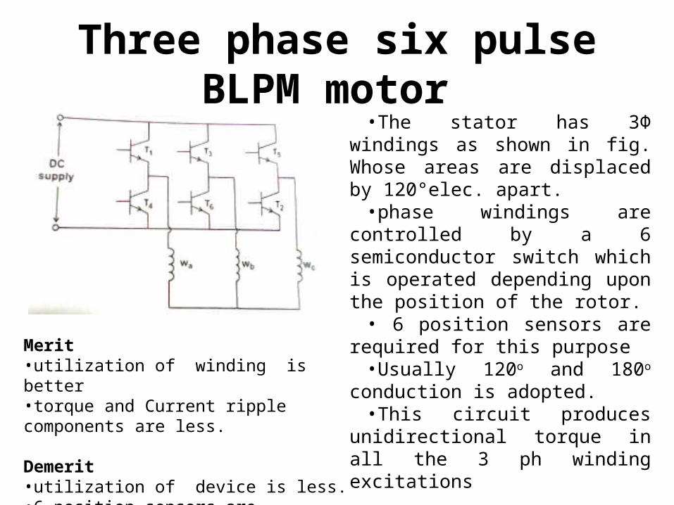
Three phase six pulse BLPM motor •The stator has 3Φ windings as
shown in fig. Whose areas are displaced by 120°elec. apart. •phase windings are controlled by a 6
semiconductor switch which is operated depending upon the position of the rotor.• 6 position sensors are required for
this purpose •Usually 120o and 180o conduction is
adopted.•This circuit produces unidirectional
torque in all the 3 ph winding excitations
Merit •utilization of winding is better•torque and Current ripple components are less.
Demerit •utilization of device is less. •6 position sensors are required.
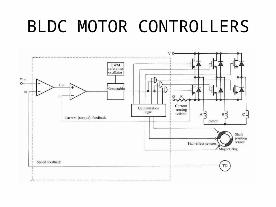
BLDC MOTOR CONTROLLERS
BLDC MOTOR CONTROLLERS• The rotor shaft position is sensed by a Hall-effect sensor, a
slotted optical disk, or some other transducer, providing signals.
• These signals are 'decoded' by combinatorial logic to provide the firing signals for 120° conduction on each of the three phases.
• The commutation logic or 'rotor position decoder' therefore has six outputs which control the upper and lower phaseleg transistors.
• Programmable logic arrays, gate arrays, and EPROMS are all suitable for this function.
• In general there will be level-shifting circuits to buffer the outputs of the logic circuit and provide the drive to the power devices.

BLDC MOTOR CONTROLLERS• The basic forward control loop is a voltage control,
implemented by a mono stable clocked at a fixed reference frequency, which is typically a few kHz. In general it is desirable to make this frequency ultrasonic to minimize noise.
• The use of AND gates as a simple way of combining the commutation and chopping signals to the lower transistors
• To implement current (torque) feedback and speed feedback in the same way as for the d.c. motor, and generally this results in a well-behaved system although compensation may be necessary in either or both loops to improve stability and transient response.