personal simulation workshop - aircraftdesign.nuaa.edu.cnaircraftdesign.nuaa.edu.cn/pd-2010/1-4...
TRANSCRIPT
Powerplant considerations
航空宇航学院

航空宇航学院
Synthesis Process
1. Specification
2. Configuration A
3. Flight regime / Powerplant
4. Fuselage layout
5. Wing configuration 1
6. Lift, drag, mass
7. performance
8. Stage one optimization:T/Mg, mg/S
8. Stage two optimization: referee design
8. Configuration comparison
9. Concept analysis
Configuration B Configuration C
Wing configuration 2 Wing configuration 3
航空宇航学院
Introduction
• The maximum speed is one of the more
important requirements for a specified aircraft.
• Flight regime is directly related to the type of
powerplant system.
• A general knowledge of the characteristics of
various powerplants is necessary to make
correct selection of powerplant type.

航空宇航学院
Outline
• Powerplant (Propulsion) Characteristics
• Types of Powerplant
• Typical Engine Parameters
• Flight Regimes of Powerplants
• Powerplant Performance Representation
• Typical Aircraft Installed Thrust and Power

航空宇航学院
Powerplant Characteristics
• Thrust– The thrust developed by an engine is the rate of change of
momentum imposed upon propelling medium
– m_bar is mass of propelling medium
– v is velocity of propelling medium
– For an air breathing engine (jet propulsion)
( )d
T mvdt
0 0( ) ( )j F j j jT m V V m V p p A 0( )jT m V V
M is mass flow through the engine per unit time
V0 is the aircraft speed
Vj is the jet velocity

航空宇航学院
Powerplant Characteristics
• Thrust– To compare different types of engine, a specific
thrust is defined as:
0( )SP j
TT V V
m

航空宇航学院
Powerplant Characteristics
• Efficiency
– The overall efficiency of a powerplant system depends
on:
• a ideal efficiency
• the various mechanical and thermal efficiencies of the engine
• air intake
• nozzle
航空宇航学院
Powerplant Characteristics
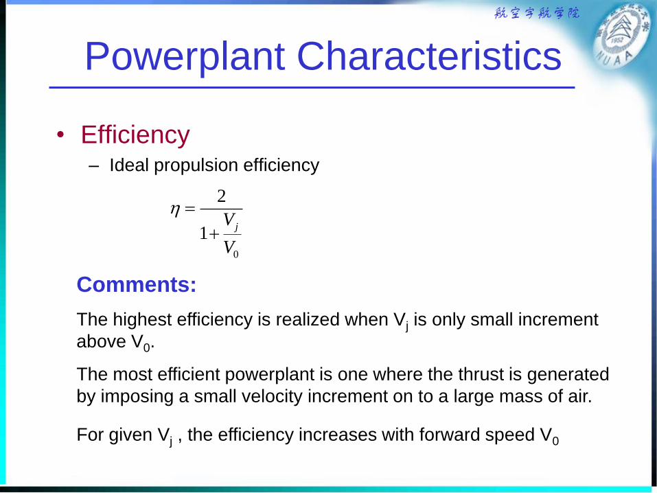
• Efficiency– Ideal propulsion efficiency
Comments:
The highest efficiency is realized when Vj is only small increment
above V0.
The most efficient powerplant is one where the thrust is generated
by imposing a small velocity increment on to a large mass of air.
For given Vj , the efficiency increases with forward speed V0
0
2
1jV
V
航空宇航学院
Powerplant Characteristics
• Noise
– The primary sources of engine noise
• The airflow interactions with the rotating
components
• The exhaust gases
– Noise can be an important consideration
• Quieter commercial aircraft
• Stealth consideration
航空宇航学院
Powerplant Characteristics
• Relationship between power and thrust
of propeller propulsion
T = P/V0
P is the power
V0 is flight speed
is propeller efficiency

航空宇航学院
Types of Powerplant
• Piston Engines
• Gas Turbines
– Jet engines
– Afterburning/reheat engines
– Turbofan engines
• Low bypass ratio engines
• High bypass ratio engines
– Turboprop engines
• Others
– Ramjet
– Rocket
– Electric powered propeller
航空宇航学院
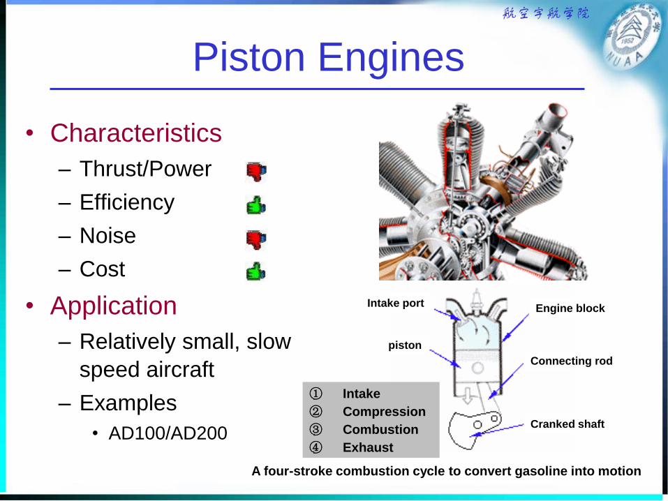
Piston Engines
• Characteristics
– Thrust/Power
– Efficiency
– Noise
– Cost
• Application
– Relatively small, slow
speed aircraft
– Examples
• AD100/AD200
A four-stroke combustion cycle to convert gasoline into motion
Cranked shaft
piston
Connecting rod
Engine blockIntake port
① Intake
② Compression
③ Combustion
④ Exhaust

航空宇航学院
Turbojet Engines (Basic Jet)
• Characteristics
– Thrust/Power
– Efficiency
– Noise
– Cost
• Application
– Fighter,Trainer
– Examples
• F-7(China)

航空宇航学院
Turbofan Engines
Turbofan is evolved from the turbojet essentially by increasing the size of the
first-stage compressor to the point where it acts as a ducted fan blowing air
past the "core" of the engine.

航空宇航学院
Turbofan Engines
• High and low bypass ratio engines.
– What is bypass ratio ?
• the ratio of how much air goes through the fan, to how
much goes through the engine.
– Typical bypass ratios:
• 1:1 for a low bypass
• 5:1 or more for a high bypass.
– Application
• Low bypass engines are more efficient at higher speeds,
and are used on planes such as military aircraft.
• High bypass engines are used in commercial airliners.
航空宇航学院
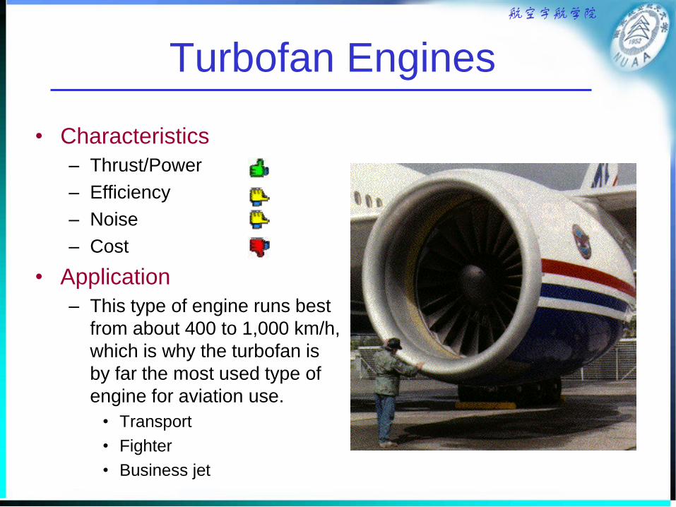
Turbofan Engines
• Characteristics
– Thrust/Power
– Efficiency
– Noise
– Cost
• Application
– This type of engine runs best
from about 400 to 1,000 km/h,
which is why the turbofan is
by far the most used type of
engine for aviation use.
• Transport
• Fighter
• Business jet

航空宇航学院
Afterburning Engines
• What is Afterburning Engines
– A jet or turbofan engine with afterburner.
• What is afterburner ?
– The jet engine afterburner is an extended exhaust section
containing extra fuel injector nozzles.
• In what case afterburning is need ?
– Performance requirements demand very high thrust for a
short period of time
• Transonic acceleration
• Supersonic dash

航空宇航学院
Turboprop Engines
• Turboprops are similar to turbofans in that they incorporate
an extra set of turbine blades used to drive the propeller.
• Unlike the turbofan engines, nearly all the thrust produced by
a turboprop is from the propeller, hardly any thrust comes
from the exhaust.
航空宇航学院
Turboprop Engines
• Thrust
– Typically range from 300 to 4000 kW power output
• Efficiency
– very efficient over a fairly wide range of speeds
• Noise
• Drawback: they have propellers.
• Application
– Smaller and slower planes such as commuter aircraft that fly
to the smaller airports.
– Large transport aircraft
• The general public does not like propellers, as they appear to
be old-fashioned and unsafe.
• The military knows better and uses them on several large
transport aircraft.
航空宇航学院
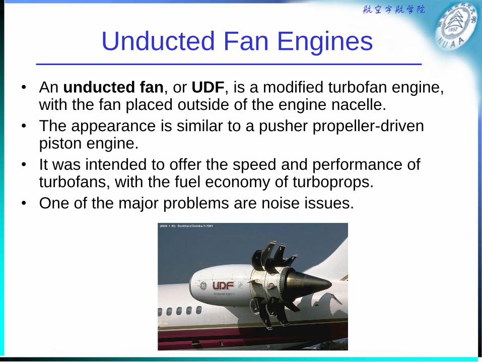
Unducted Fan Engines
• An unducted fan, or UDF, is a modified turbofan engine, with the fan placed outside of the engine nacelle.
• The appearance is similar to a pusher propeller-driven piston engine.
• It was intended to offer the speed and performance of turbofans, with the fuel economy of turboprops.
• One of the major problems are noise issues.

航空宇航学院
Typical Engine Parameters
• Specific Thrust
– The higher values relate to those engines
which have lower relative mass flows

航空宇航学院
Typical Engine Parameters
• Frontal area
– Capture area ranges from the intake area of a jet
or bypass engine to the fan or propeller disc area.

航空宇航学院
Typical Engine Parameters
• Disc loading

航空宇航学院
Typical Engine Parameters
• Propulsive Efficiencies– Typical variation of ideal powerplant efficiencies as function
of Mach number
Recall ideal
propulsion efficiency
0
2
1jV
V
航空宇航学院
Flight Regimes of Powerplants
• Propeller Engines
– Efficiency change
• The efficiency increases rapidly with speed, because the
thrust from a propeller is derived by the addition of a small
velocity change to a large mass of air.
– Efficiency range
• Propeller for small, slow aircraft: < 70%
• At somewhat higher speed (M0.3-0.65): 85-90 %
– Applications
• For flight speed up to M0.5
– piston/propeller or turbine/propeller
• For flight speed ranging from M0.5 to M 0.7
– turbine/propeller

航空宇航学院
Flight Regimes of Powerplants
• Turbofan Engines
– Aircraft with flight speed ranging from M0.7 to M 0.9
• Turbofan engines with the higher bypass ratios (4-8) are used on
relatively longer range aircraft.
– Some aircraft at M0.5 to 0.7.
• While their efficiency at these lower speeds is less than that of a
propeller engine, their relatively small size can enable a more
compact aircraft to be designed which is more efficient.
• Such aircraft are often in the small business/executive class.
– Application to supersonic flight
• Turbofan engines with the low bypass ratios(0.4-1.0) are used on
military aircraft, such as fighters.
航空宇航学院
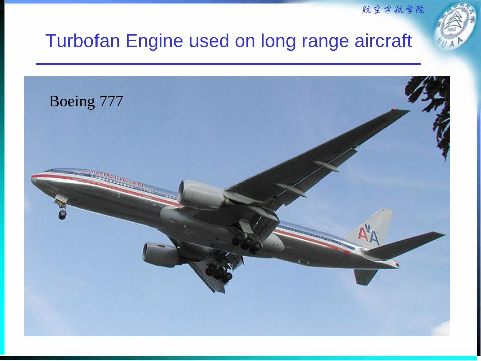
Turbofan Engine used on long range aircraft
Boeing 777

航空宇航学院
Turbofan Engine used on business jet
P&WC PW308A

航空宇航学院
Turbofan Engine used on the fighter
F-22
Pratt & Whitney F119-PW-100

航空宇航学院
Flight Regimes of Powerplants
• Basic Jet Engines
– There is little future application for a basic
jet engine due to the development of the
afterburning low bypass ratio engines.
航空宇航学院
Powerplant Performance Representation
• Thrust Representation
– Flight speed
– Flight altitude
– Engine operation conditions
• Specific Fuel Consumption
– Flight speed
– Flight altitude
– Engine operation conditions

航空宇航学院
Thrust Representation
• Turbojet & Turbofan
– T = T0
• T0 is the datum sea level static dry thrust
• T is the available operating thrust at any given
condition
• is a factor dependent on flight speed, altitude, engine
operation conditions and bypass ratio,R
– For 0<MN<0.9: = F [K1 + K2 R+(K3 + K4 R)MN]s
– For MN > 0.9: = F [K1 + K2 R+(K3 + K4 R)(MN-0.9)]s

航空宇航学院
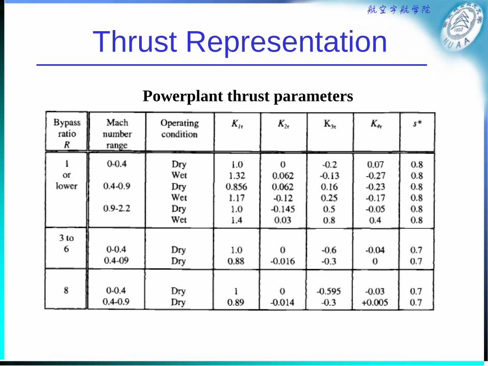
Thrust Representation
• Turbojet & Turbofan– For 0<MN<0.9: = F [K1 + K2 R+(K3 + K4 R)MN]s
– For MN > 0.9: = F [K1 + K2 R+(K3 + K4 R)(MN-0.9)]s
» S is altitude factor ( see table 3.2)
» F is a factor to allow for use of afterburning
» TW and TD are the sea level static thrust values in wet
and dry operation conditions respectively
» K1 , K2 , K3 , K4 are assumed to be constant for a
given powerplant in defined Mach number and
operating condition ( see table 3.2).
(1.32 0.062 )
W
D
T
TF
R
航空宇航学院
Thrust Representation
Powerplant thrust parameters
航空宇航学院
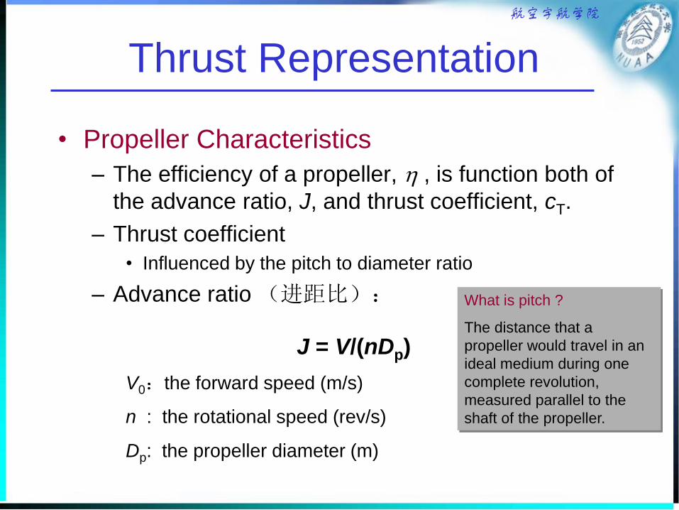
Thrust Representation
• Propeller Characteristics
– The efficiency of a propeller, , is function both of
the advance ratio, J, and thrust coefficient, cT.
– Thrust coefficient
• Influenced by the pitch to diameter ratio
– Advance ratio (进距比):
J = V/(nDp)
V0:the forward speed (m/s)
n : the rotational speed (rev/s)
Dp: the propeller diameter (m)
What is pitch ?
The distance that a
propeller would travel in an
ideal medium during one
complete revolution,
measured parallel to the
shaft of the propeller.
航空宇航学院
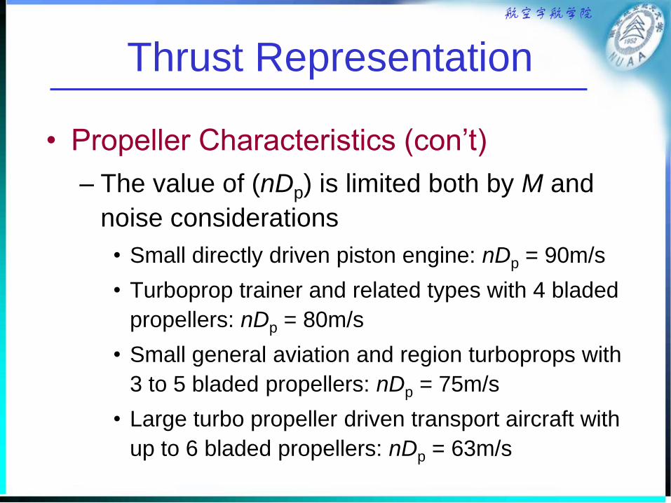
Thrust Representation
• Propeller Characteristics (con’t)
– The value of (nDp) is limited both by M and
noise considerations
• Small directly driven piston engine: nDp = 90m/s
• Turboprop trainer and related types with 4 bladed
propellers: nDp = 80m/s
• Small general aviation and region turboprops with
3 to 5 bladed propellers: nDp = 75m/s
• Large turbo propeller driven transport aircraft with
up to 6 bladed propellers: nDp = 63m/s

航空宇航学院
Thrust Representation
• Propeller Characteristics (con’t)
– The maximum efficiency
• For 0.4<J<1.0 =0.82J0.4
• For J>1.0 =(0.82J1.6) /(10 j)
– Where j=0.3(logJ) 2.4
– The limited efficiency
• limit=1.8z0.15(nDp) 1.6JP00.095 10 –7
– P0 is max. engine shaft power (kW)
– is the air density
– z is the number of propeller blades

航空宇航学院
Thrust Representation
• Propeller Characteristics (con’t)
– The thrust in flight conditions
• T= P0 10 3/ V0 N
• T= P0 10 3/J(nDp) N
– The thrust in static conditions
• Ts= (cT)s (nDp) 2Dp2 N
– (cT)s = 0.0085 z 0.15(P0/A)0.65
» (P0/A) is power disc loading (1.273 P0/Dp2)
» P0 is the static power (max. rated), kW

航空宇航学院
Thrust Representation
• Propeller Characteristics (con’t)
– The propeller rotational speed, n, is chosen
in conjunction with the diameter to give the
best compromise between tip speed and
efficiency in a given (nDp). Typically :
• Direct drive piston engines n = 45 rev/s
• Geared turboprop engines n = 433(P0)-0.4 rev/s

航空宇航学院
Thrust Representation
• Propeller Characteristics (con’t)
– Typical power disc loading
• Direct drive piston engines: (P0/A) = 4.7 P0 0.5 kw/m2
• Turboprops: (P0/A) = 1.45 P0 10 5 /(nDp)2 kw/m2
– The diameter of the propeller
• Direct drive piston engines: Dp = 0.52P00.25 (m)
• Turboprops: Dp = 3(nDp) P00.365 10 -3 (m)
– Where P0 is defined by Eq. (3.9m) in the textbook

航空宇航学院
Thrust Representation
• Turboprop
– Maximum power take-off conditions
• At the take-off stage
Ts = 1.73z 0.15(nDp)2.7 P0
0.095 10 –4 N
• At second climb stage
Tss = (0.82 P0 10 3 )/ [(nDp)V 0.6] N
» V = 1.1(VUS)HH
» VUS is true unstick speed (离地速度)
航空宇航学院
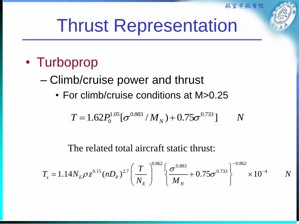
Thrust Representation
• Turboprop
– Climb/cruise power and thrust
• For climb/cruise conditions at M>0.25
1.05 0.883 0.733
01.62 [ / ) 0.75 ]NT P M N
The related total aircraft static thrust:
0.8620.8620.883
0.15 2.7 0.733 41.14 ( ) 0.75 10s E P
E N
TT N z nD N
N M
航空宇航学院
Thrust Representation
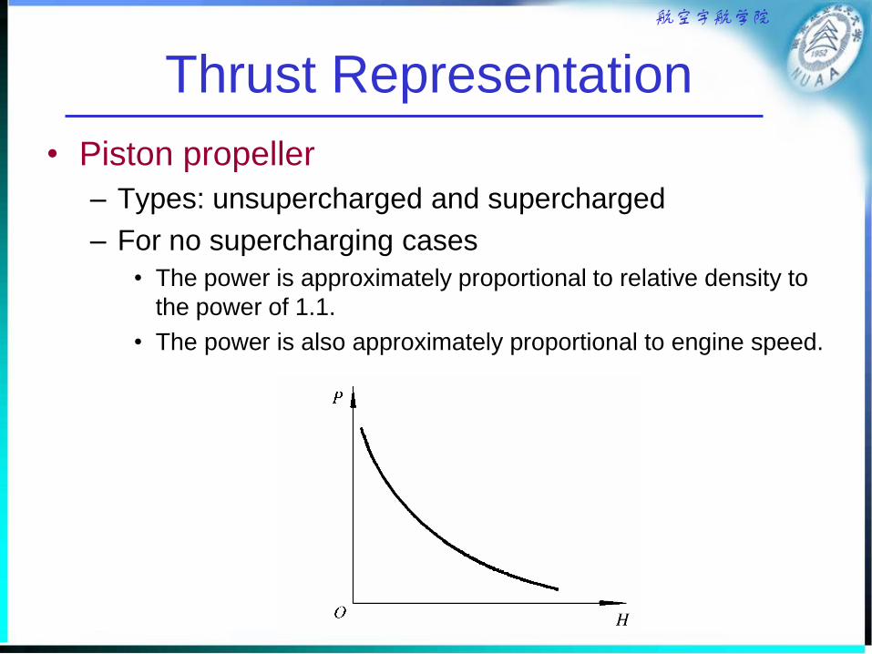
• Piston propeller
– Types: unsupercharged and supercharged
– For no supercharging cases
• The power is approximately proportional to relative density to
the power of 1.1.
• The power is also approximately proportional to engine speed.

航空宇航学院
Thrust Representation
• Piston propeller
– For supercharging cases
• Maintain sea level power to 5 km altitude, or
• increase sea level power by a significant amount.
The power then decreases as the relative, density
decreases, as unsupercharged engine.
– Variation of power with forward speed is
negligible

航空宇航学院
Thrust Representation
• Piston propeller
– The static thrust
Ts = 42P00.85 N (per engine)
– Climb
Tcl = (0.82P 10 3) / [ Vcl0.6(nDp)
0.4] N
• Assuming that max. continuous climb rating is
90% and typically, (nDp) = 90 m/s
Tcl = 0.1221.1P0 10 3 / Vcl0.6 N

航空宇航学院
Thrust Representation
• Piston Propeller
– Cruise
• Cruise speed less than 90m/s: J <= 1.0
Tcr= 0.1151.1P0 10 3 / Vcl0.6 N
• Cruise speed greater than 90m/s: J >1.0
Tcr= 0.341.1P0 10 3 / Vcl0.84 N

航空宇航学院
Fuel Consumption Characteristics
• Turbojet and Turbofan
– Dry (no reheat)
c = c’(1-0.15R0.65)[1+0.28(1+0.063R2)MN]0.08
– Up to 11 km, c should be assumed to be constant
– c is the specific fuel consumption
– R is the bypass ratio
– c’ is a factor which should be determined by reference
to the actual specific fuel consumption of a given
powerplant at a critical condition
» Supersonic engine R<1.0 c’ = 0.95 N/N/h
» Low bypass ratio subsonic engine c’ = 0.85 N/N/h
» Large subsonic turbofan c’ = 0.70 N/N/h

航空宇航学院
Fuel Consumption Characteristics
• Turbojet and Turbofan
– Dry (no reheat)
• When the engine is operated at some thrust less
than the design value in a given flight condition
– cOD = c[1+0.01(T/TOD – 1)] for T/TOD <10
» cOD and TOD refer to the off-design conditions
– Afterburning (reheat)
– c= 1.05(TW/TD)(1+0.17MN) 0.08 N/N/h
» This applies up to 11 km, above which c should be
assumed to be constant with altitude.

航空宇航学院
Fuel Consumption Characteristics
• Turboshaft Engine
– The specific fuel consumption in climb/cruise condition
(c)p = 2.88(1-0.025P0 10 -3 )(1-0.2MN) N/kW/h
– In terms of thrust
(c)T = MN 0.117(1-0.025P0 10 -3 )(1-0.2MN)/ N/kW/h
• The above equations refer to shaft power, not flight power.

航空宇航学院
Fuel Consumption Characteristics
• Piston Engines
– In terms of power settings
• (c)p = c’[1+0.24(P0/Pr)][1+1.5(Pr/P01.1)] N/kW/h
– P0 is the maximum rated power
– Pr is the power required in a given flight condition
– c’ depends on the actual engine and its mode of operation,
typically is 1.0 or less.
– In terms of thrust
• (c )T = (c)p (V/) 10 -3 N/N/h

航空宇航学院
Powerplant Mass
• The mass of a given type of powerplant
is closely related to the static thrust.
• Typical values will be presented in the
chapter 6 for mass prediction.

航空宇航学院
Typical Aircraft Installed thrust and Power
Typical static thrust to weight ratios-Jet and fan driven aircraft
航空宇航学院
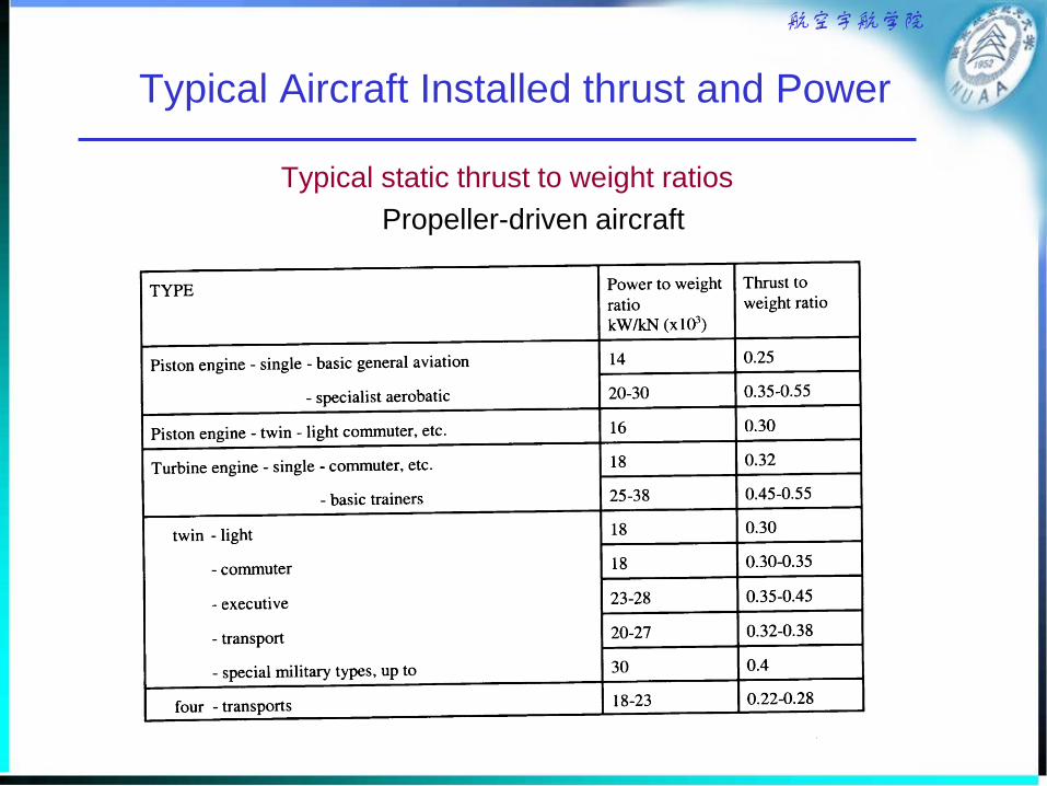
Typical Aircraft Installed thrust and Power
Typical static thrust to weight ratios
Propeller-driven aircraft

航空宇航学院
Summary: The purpose of this chapter
• To gain/review a general knowledge of the
characteristics of various powerplants.
• To obtain the thrust and efficiency formula for
performance evaluations, given some preliminary
parameters (static thrust T0, (nDp) , number of blades).
– Thrust/Power available at takeoff
– Thrust/Power available at climb
– Thrust/power available at cruise