perspective on r&d needs for gas turbine power generation
TRANSCRIPT
1
Perspective on R&D Needs for Gas
Turbine Power Generation
Eli Razinsky
Solar Turbine Incorporated
2010 UTSR Workshop
October 26, 2011
2
• Overview
• Specific Requirements
Research Requirements
3
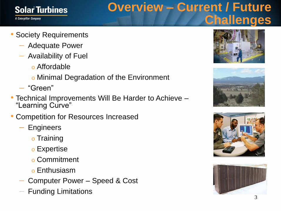
Overview – Current / Future Challenges
• Technical Improvements Will Be Harder to Achieve –“Learning Curve”
• Society Requirements
Adequate Power
Availability of Fuel
o Affordable
o Minimal Degradation of the Environment
“Green”
• Competition for Resources Increased
Engineers
o Training
o Expertise
o Commitment
o Enthusiasm
Computer Power – Speed & Cost
Funding Limitations

4
Overview – Required Approach
• Pragmatic Research
Address Critical Problems & Requirements
PerformancePerformance
OptimizedOptimized
ProductProduct
EmissionsEmissions
RAMRAM--DD LifeLife--
Cycle Cycle
CostsCosts
PerformancePerformance
OptimizedOptimized
ProductProduct
EmissionsEmissions
RAMRAM--DD LifeLife--
Cycle Cycle
CostsCosts
Must be Applicable in Industrial Design/Analysis Environment
o Iterative Multi-Disciplinary Process
o Demanding Design & Development Schedules/Costs
o Manufacturability
o Robust
Validation/Calibration Mandatory
Transferable
• Collaboration
Universities
OEM
OEM Value Stream
• Train the Next Generation of Turbomachinery Engineers

5
• Status
Still Has Limitations, e.g. Heat Transfer
Can’t Completely Replace Testing
Unsteady, DES, LES Not Practical Yet
Turbomachinery CFD History
• CFD Capabilities Progressed Significantly
Model Fidelity
Flow Physics
MODEL FIDELITY SIGNIFICANTLY INCREASED
Meanline
1-D Models
1950’s
Airfoil
3-D Navier-Stokes
1980’s
Multistage
3-D Steady &
Single Stage
Unsteady
1990’s
Airfoil
2-D Inviscid
Blade-to-Blade
& Streamline
1960’s
Airfoil
3-D Inviscid
Euler
1970’s
Multistage 3-D
Unsteady
2000’s
More Testing
More Empiricism
More Exact
Less Testin
g
Continuous Valid
ation and C
alibratio
n
More Detailed M
odel
Increased Computational
Requirements
Simplifi
ed Model
Low Computational
Requirements
Meanline
1-D Models
1950’s
Airfoil
3-D Navier-Stokes
1980’s
Multistage
3-D Steady &
Single Stage
Unsteady
1990’s
Airfoil
2-D Inviscid
Blade-to-Blade
& Streamline
1960’s
Airfoil
3-D Inviscid
Euler
1970’s
Multistage 3-D
Unsteady
2000’s
More Testing
More Empiricism
More Exact
Less Testin
g
Continuous Valid
ation and C
alibratio
n
Continuous Valid
ation and C
alibratio
n
More Detailed M
odel
Increased Computational
Requirements
Simplifi
ed Model
Low Computational
Requirements
• Application Transitioned
From Post Design Analysis
To Fully Integrated Critical Tool For Design of Turbomachinery
• Product Payoff
Reduced Development Time/Cost
Improved Performance

6
Reliable, Available
Commercial,
University & Gov.
CFD Software
Comprehensive
Technical
Skills,Training
and Experience
Extensive
Data-Base
Continuous
Upgrades,
Validations
and Calibrations
High Performance
Computer System
Advanced
High Fidelity
CFD
CFD Future Success Can be Greatly Enhanced by Committed Integrated Approach
Turbomachinery CFD – Future

7
Perspective on R&D Needs for
Gas Turbine Power Generation –
Combustion
8
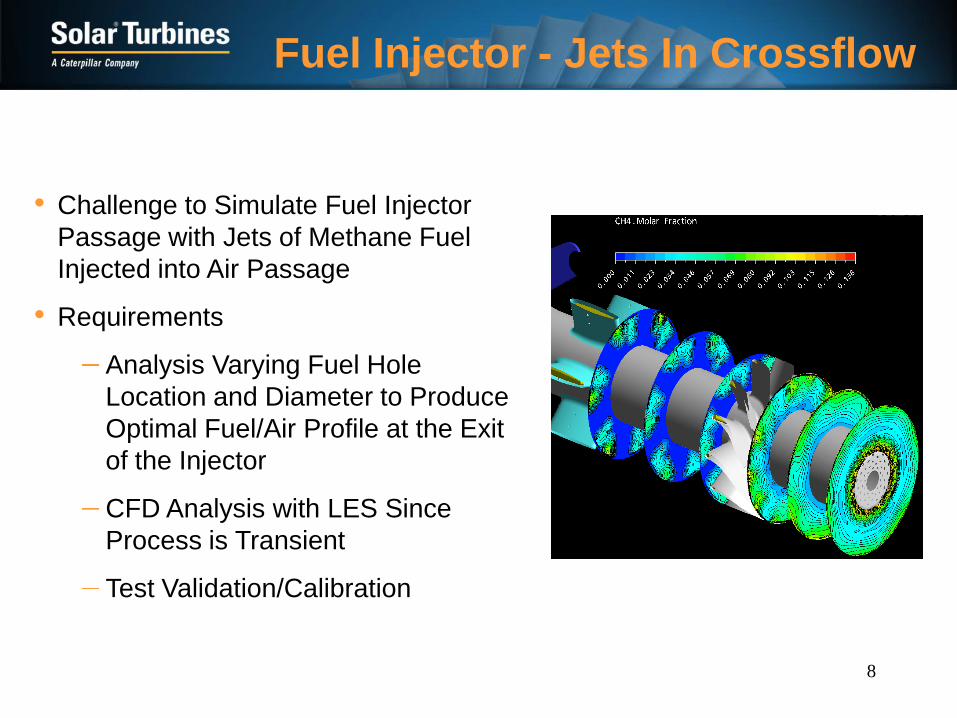
Fuel Injector - Jets In Crossflow
• Requirements
Analysis Varying Fuel Hole
Location and Diameter to Produce
Optimal Fuel/Air Profile at the Exit
of the Injector
CFD Analysis with LES Since
Process is Transient
Test Validation/Calibration
• Challenge to Simulate Fuel Injector
Passage with Jets of Methane Fuel
Injected into Air Passage

Combustor Liner Durability
Section 1” From Injector Exit
Section 4” From Injector Exit
Section 1” From Injector Exit
Section 4” From Injector Exit
• Challenge to Predict Liner Temperature
Complex Flowfields
Chemical Reaction (CR)
Cooling
Conduct Blind Test CFD Conjugate Heat Transfer
o CFD by Partner Universities?
o CFD Options
RANS, LES etc.
Different Reaction Mechanisms
• Requirements
Conduct Combustor Testing
o Obtain Liner and Heat Flux
o Effect of CR on Heat load
o Effect of Primary Zone Conditions
9

10
Combustor Exit Profile
0
20
40
60
80
100
1000 1500 2000 2500
Combustor Exit Temperature
Co
mb
us
tor
Ex
it S
pa
n
0
20
40
60
80
100
1000 1500 2000 2500
Combustor Exit Temperature
Co
mb
us
tor
Ex
it S
pa
n
0
20
40
60
80
100
1000 1500 2000 2500
Combustor Exit Temperature
Co
mb
us
tor
Ex
it S
pa
n
0
20
40
60
80
100
1000 1500 2000 2500
Combustor Exit Temperature
Co
mb
us
tor
Ex
it S
pa
n
Durable Turbine Dependant on
Combustor Exit Temperature
• Effusion Cooling Plays Dual Role
– Impacts Exit Cone Metal Temperature
– Impacts Combustor Exit Temperature Profile
Effusion
Cooling
• Need to Characterize Effect of Effusion Cooling Blowing Ratio &
Number of Rows on Combustor Exit Temperature Profile
• CFD Validation/Calibration

11
Perspective on R&D Needs for
Gas Turbine Power Generation –
Aero/Thermal

12
Blade/Platform Heat Load Assessment
• Challenge To Predict Adiabatic Wall Temperature and Heat
Transfer Coefficient Accounting for
GT2010-22702
GT2010-22702
Platform Air Leakage
Disk Cavity Buffer Air
GT2010-22702
Platform Air Leakage
Disk Cavity Buffer Air
Platform Air
Leakage
Disk Cavity
Buffer Air
GT2010-22702
Platform Air Leakage
Disk Cavity Buffer Air
GT2010-22702
Platform Air Leakage
Disk Cavity Buffer Air
Platform Air
Leakage
Disk Cavity
Buffer Air
Often Critical
Location
Near Tip (Difficult to
Cool Internally)
Near Platform
& Platform
Often Critical
Location
Near Tip (Difficult to
Cool Internally)
Near Platform
& Platform
Often Critical
Location
Near Tip (Difficult to
Cool Internally)
Near Platform
& Platform
Inlet Temperature Profile
Buffer/Leakage Air Effects
Hot Streaks etc.
• Require
Models to Account for Effects Early in Design Cycle
CFD Based Modeling for Detailed Design
Experimental Validation/Calibration

13
Blade/Platform Cooling Configuration Design
• High Heat Load Due to the Flat Combustor Outlet Temperature
Profile (Premixed Lean)
• Large Heat Load Variation
• Heat Load Prediction is Difficult
• Few Papers Related to the Platform Heat Transfer
(External/Internal)
• Casting Challenges
• Need Innovative Cooling Design Concepts & Validation/Calibration
GT2005-68415
14
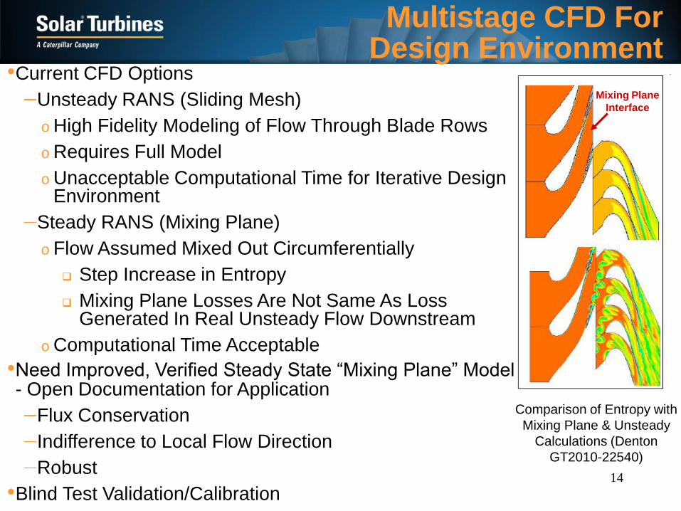
Multistage CFD For Design Environment
•Current CFD Options
Unsteady RANS (Sliding Mesh)
o High Fidelity Modeling of Flow Through Blade Rows
o Requires Full Model
o Unacceptable Computational Time for Iterative Design Environment
Steady RANS (Mixing Plane)
o Flow Assumed Mixed Out Circumferentially
Step Increase in Entropy
Mixing Plane Losses Are Not Same As Loss Generated In Real Unsteady Flow Downstream
o Computational Time Acceptable
Comparison of Entropy with
Mixing Plane & Unsteady
Calculations (Denton
GT2010-22540)
Mixing Plane
Interface
•Need Improved, Verified Steady State “Mixing Plane” Model - Open Documentation for Application
Flux Conservation
Indifference to Local Flow Direction
Robust
•Blind Test Validation/Calibration
15
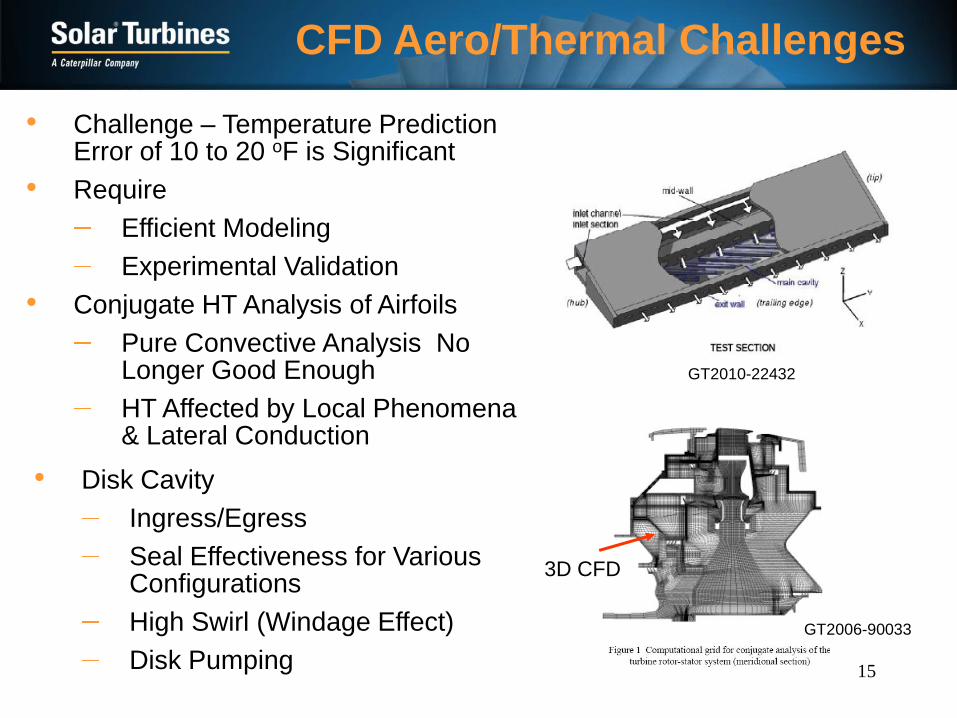
CFD Aero/Thermal Challenges
• Challenge – Temperature Prediction Error of 10 to 20 oF is Significant
• Require
Efficient Modeling
Experimental Validation
• Conjugate HT Analysis of Airfoils
Pure Convective Analysis No Longer Good Enough
HT Affected by Local Phenomena & Lateral Conduction
• Disk Cavity
Ingress/Egress
Seal Effectiveness for Various Configurations
High Swirl (Windage Effect)
Disk Pumping
GT2010-22432
3D CFD
GT2006-90033
16
Perspective on R&D Needs for
Gas Turbine Power Generation –
Materials
17
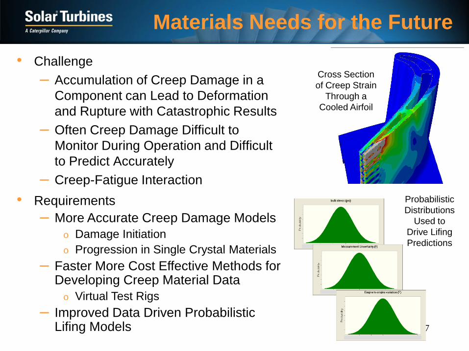
• Challenge
– Accumulation of Creep Damage in a
Component can Lead to Deformation
and Rupture with Catastrophic Results
– Often Creep Damage Difficult to
Monitor During Operation and Difficult
to Predict Accurately
– Creep-Fatigue Interaction
Materials Needs for the Future
Cross Section
of Creep Strain
Through a
Cooled Airfoil
Probabilistic
Distributions
Used to
Drive Lifing
Predictions
• Requirements
– More Accurate Creep Damage Models
o Damage Initiation
o Progression in Single Crystal Materials
– Faster More Cost Effective Methods for Developing Creep Material Data
o Virtual Test Rigs
– Improved Data Driven Probabilistic Lifing Models
18
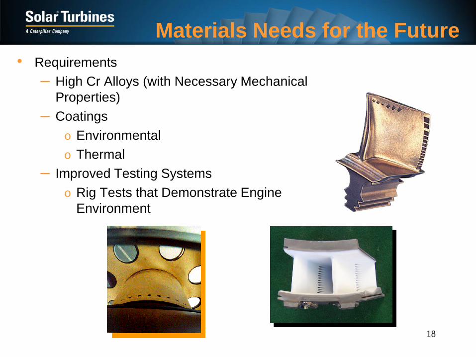
• Requirements
– High Cr Alloys (with Necessary Mechanical
Properties)
– Coatings
o Environmental
o Thermal
– Improved Testing Systems
o Rig Tests that Demonstrate Engine
Environment
Materials Needs for the Future

19
Offshore
Application
COG
Application
• Material Durability when Exposed to
Various Operating Environments
H2S/H2/Offshore
Coke Oven Gas
Na2SO4, K2SO4, CaSO4 & MgSO4
• Degradation Mechanisms Including
High Temperature Oxidation, Hot
Corrosion, and Sulfidation
• Require New Metals, Coatings &
Cooling
Turbine Blade Tip
Hot Corrosion
Materials Needs for the Future
Injector Tip
Degradation

20