peter legg - closure and rehabilitation of waste disposal ... · plastics sa, midrand, ... –...
TRANSCRIPT
CLOSURE AND REHABILITATION OF WASTE
DISPOSAL FACILITIESPeter Legg
Workshop on Capping Design in South AfricaPlastics SA, Midrand, 29 June 2016

LANDFILL COVERS• OBJECTIVES OF COVER SYSTEMS• DESIGN ASPECTS• COVER COMPONENTS• STABILITY• DRAINAGE • CONCLUDING REMARKS

Objectives of Capping• Contain the wastes• Manage leachate production by controlling the
ingress of water into the waste• Prevent uncontrolled escape of landfill gas and
odours or the entry of air into the wastes• Provide protection for the wastes• Accommodate environmental control measures such
as gas vents, etc.• Provide physical separation between waste and
humans, animals and plants.(Daniel and Koerner, 1993; United Kingdom Department of the Environment,1995; Jesionek et al, 1995)
World Bank / IFC and US EPA“At final closure of the landfill or upon closure of any cell, cover the landfill or cell with a final cover designed and constructed to:• Provide long-term minimization of migration of liquids
through the closed landfill;• Function with minimum maintenance; • Promote drainage and minimize erosion or abrasion of the
cover; • Accommodate settling and subsidence so that the cover's
integrity is maintained; and• Have a permeability less than or equal to the permeability
of any bottom liner system or natural subsoils.”
Prime Objective
• The prime objective of landfill final cover is generally accepted to be keeping water out of the waste (Daniel and Koerner, 1993).
• Isolate the waste body from the surrounding environment (both air and water environments)


Design Life• The cover system must perform these functions for an
extended period of time. The design life of a cover depends primarily on the nature of the waste, the site hydrology, and the length of time that the maintenance of the cover will be provided.
• Post-closure Care– Post-closure care period typically 30 years– Must maintain integrity and effectiveness of cover– Must maintain leachate collection– Must monitor groundwater– Must maintain and operate gas monitoring
Environmental Risk• Assess the environmental risk posed by the
waste facility– Nature of waste (hazardous or general waste)– Bottom liner or not (MRs Clause 8.4.7)– Groundwater sensitivity– Adjacent landusers (neighbours)
• Determine minimum requirements of the Regulator– In absence of strong regulations, apply “Duty of
Care” principle and international “Best practice”

Design Aspects • Landscaping requirements including
additional topsoil needs• Consider final end-use• Low permeability to minimise gas emission
and surface water infiltration• The relationship between phasing of
construction and the landscape design for the after-use
• Recirculation of leachate if required
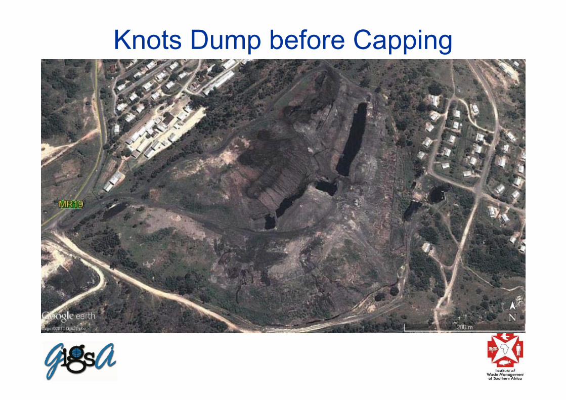
Knots Dump before Capping

Knots Dump after Phase 1 Capping

Knots Dump during Phase 2 Capping
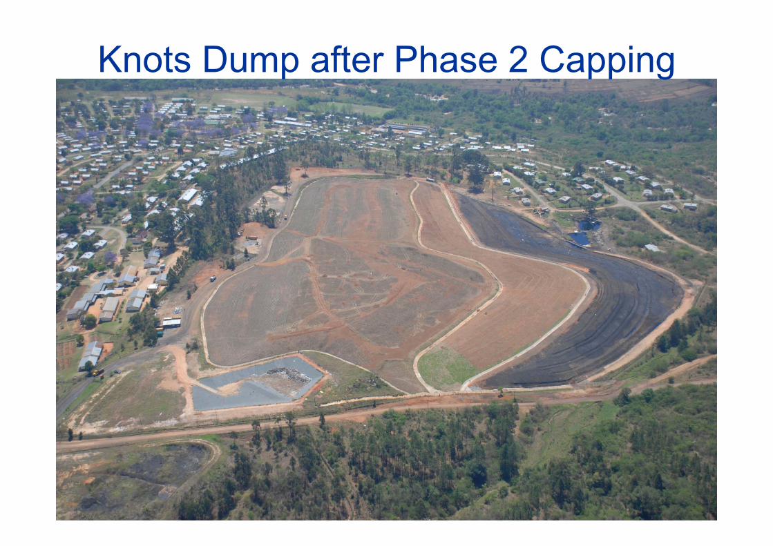
Knots Dump after Phase 2 Capping

Design Aspects (cont.)• Alterations caused by gas derived from
volatile components of the waste or decomposition products
• Robustness against settlement stresses• Stability on proposed restoration slopes• Surface water drainage• Erosion• The effects of roots and burrowing animals on
its integrity• Deformations caused by earthquakes

Design Aspects
Because of these site-specific environmental stresses and conditions, the design of a cover system can be very challenging. It is often more difficult to provide an effective hydraulic barrier layer in a cover system than in a liner system because the cover system is challenged by unknown and unquantifiable stresses that do not act on liner systems buried deep beneath the waste.

Temporary Covers• Daniel and Koerner (1993) contend that in
many cases, it could be preferable to construct a temporary cover for an actively decomposing and deforming body of waste, and then wait until substantial decomposition of the waste body has occurred before attempting to construct a final cover.
Cover ComponentsThe components of a cover comprise a
combination of some or all of the following:• Surface erosion and vegetation layer• Protection layer• Drainage layer• Barrier layer, and• Foundation or gas collection layer.
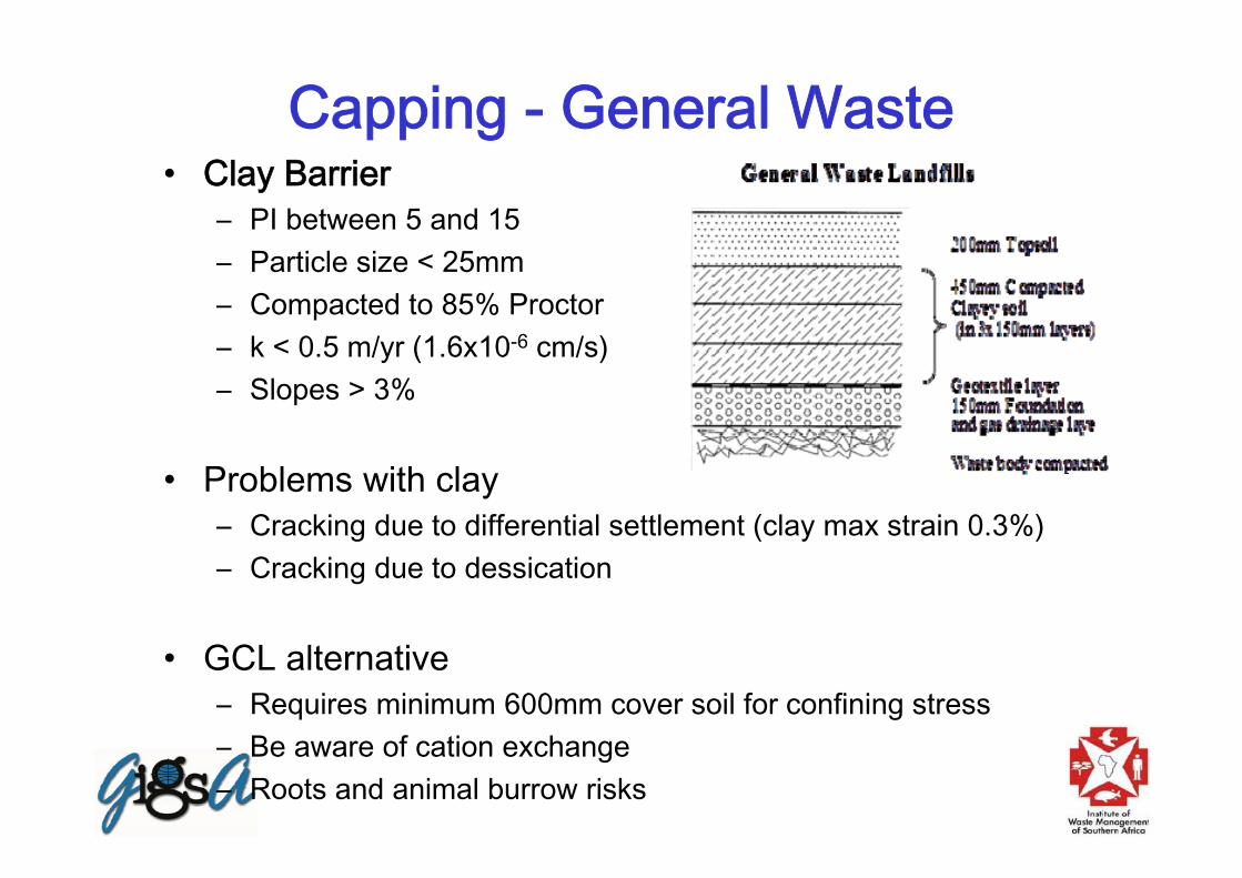
Capping - General Waste• Clay Barrier
– PI between 5 and 15– Particle size < 25mm– Compacted to 85% Proctor– k < 0.5 m/yr (1.6x10⁻⁶ cm/s)– Slopes > 3%
• Problems with clay– Cracking due to differential settlement (clay max strain 0.3%)– Cracking due to dessication
• GCL alternative– Requires minimum 600mm cover soil for confining stress– Be aware of cation exchange– Roots and animal burrow risks

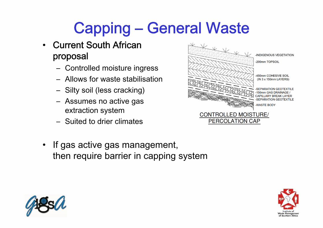
Capping – General Waste• Current South African
proposal – Controlled moisture ingress– Allows for waste stabilisation– Silty soil (less cracking) – Assumes no active gas
extraction system– Suited to drier climates
• If gas active gas management, then require barrier in capping system

Capping – Dry Cap (restricted moisture)• Hazardous waste and general
waste in wet climates • Similar to US EPA
– Surface/protection layer 600 mmthick (vegetated soil or rock);
– Filter layer (geotextile);– Drainage layer (granular or
geosynthetic);– Geomembrane barrier layer;– Low permeability soil barrier; and– Foundation layer (coarse material
which could also act as a gas venting layer).

Comments on layers• Surface layer
– Thin as possible but sufficient to support vegetation– Indigenous vegetation– Ensure erosion control, particularly until vegetation has established
• Protection layer – Use local soil, with moderate compaction– Thickness sufficient for frost penetration and/or GCL confining stress
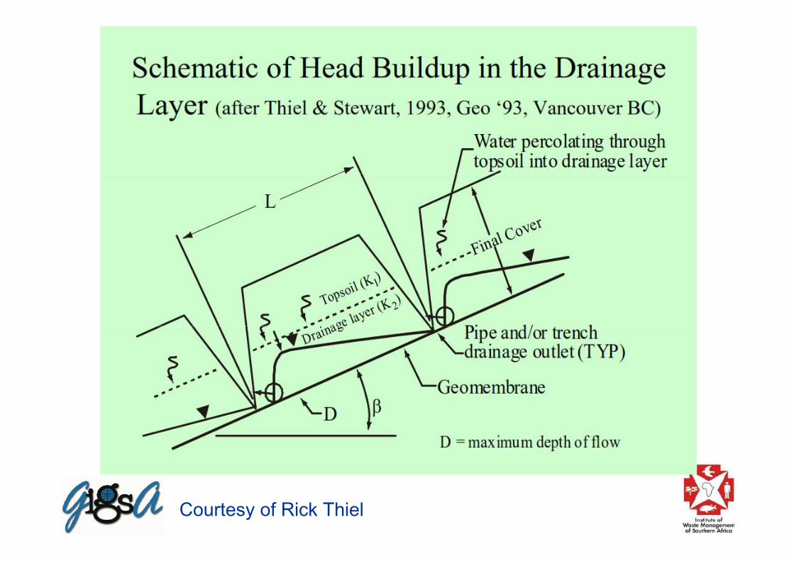
• Filter layer and drainage layer– Use geotextile filter plus stone drainage layer, or geocomposite drain– Ensure capacity for drainage of extreme design storms (stability)– Install collector pipes
• Barrier layers– Geomembrane – LLDPE better than HDPE for flexibility during
settlement (LLDPE 75% max strain vs HDPE 25% max strain)– Thickness typically 1mm to 1.5mm
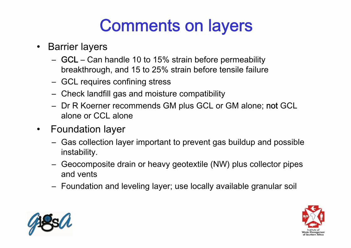
Comments on layers• Barrier layers
– GCL – Can handle 10 to 15% strain before permeability breakthrough, and 15 to 25% strain before tensile failure
– GCL requires confining stress– Check landfill gas and moisture compatibility– Dr R Koerner recommends GM plus GCL or GM alone; not GCL
alone or CCL alone• Foundation layer
– Gas collection layer important to prevent gas buildup and possible instability.
– Geocomposite drain or heavy geotextile (NW) plus collector pipes and vents
– Foundation and leveling layer; use locally available granular soil

Soil Cover
Waste
Typical Geosynthetic
Capping DetailGeomembrane
LLDPE, HDPE, PVC
Woven Geotextile separator
Sand or Soil Leveling Layer
Geogrid Reinforcing
Layer

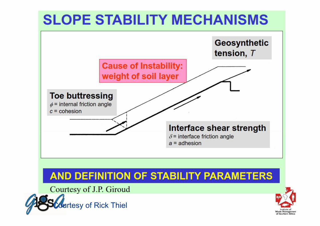
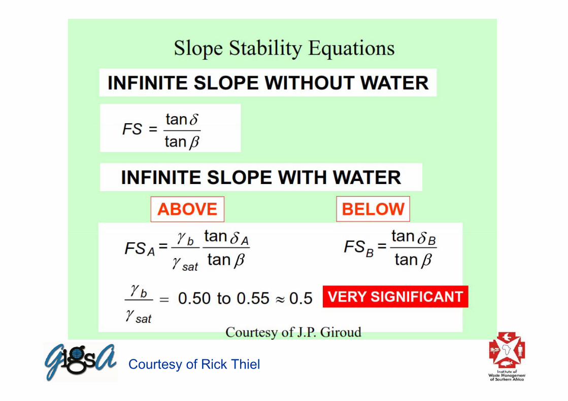
Cover stability design• Assess cover veneer stability for dry and saturated
conditions• Determine various liner interface shear strength
parameters by means of lab testing using actual materials (soils and geosynthetics)
• Ensure failure plane is above the geomembrane barrier layer so as to protect the barrier
• If necessary, use a geosynthetic reinforcement product above the geomembrane to provide stability of the cover soil.
• Stability FoS = Shear strength of veneer systemShear stress on the veneer system
Courtesy of Rick Thiel

Courtesy of Rick Thiel
Courtesy of Rick Thiel
Courtesy of Rick Thiel

Courtesy of Rick Thiel

Courtesy of Rick Thiel
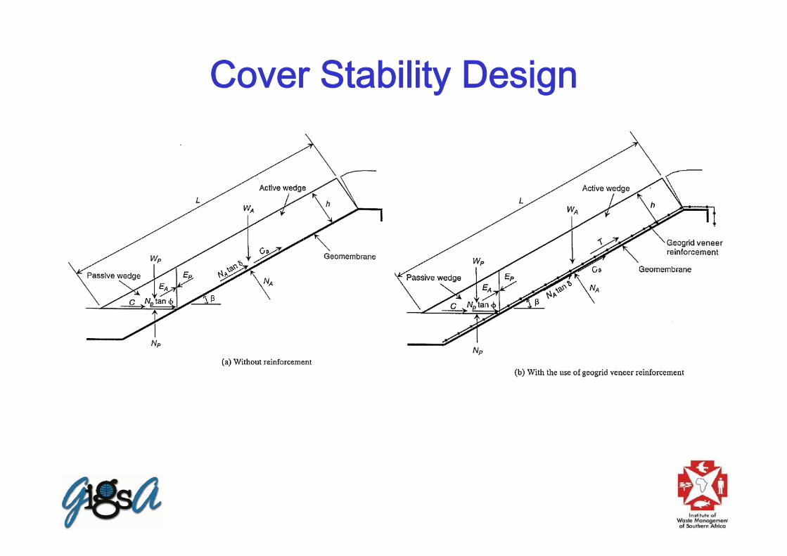
Cover Stability Design

Anchorage design

Drainage Design • Surface water drainage design is critical to prevent erosion
and instability of the cover system• Restrict free slope runoff by means of contour drains at
calculated intervals (typically 30 to 50m)• Drain cover seepage into contour drains• Size drains for 1 in 20 year rain event, plus freeboard to
handle the 1 in 50 year rain event• Design downchute drains to handle high velocities
(supercritical flow). Provide energy dissipators• Design drains as flexible structures with adequate slopes to
handle landfill settlement
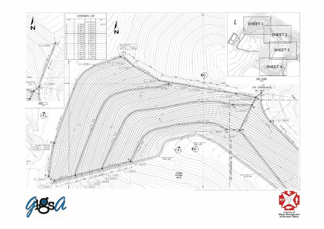


Typical contour drain with geogrid reinforcement
Concluding Remarks• The primary objective of closure design is to
isolate the waste body from the environment• Assess environmental risk based on status quo• Consider practical aspects such as final landform,
end-use and phased closure• Determine required cover system that mitigates
the environmental risks• Ensure stability of the installed cover system in
extreme rainfall events• Design surface water drainage system to protect
the installed cover

THANK YOU
Peter Legg, PrEng