p+f 04-03-14 r017 v1 r1.3 - pepperl+fuchsfiles.pepperl-fuchs.com/selector_files/navi/... ·...
TRANSCRIPT

The document was prepared using best effort. The authors make no warranty of any kind and shall not be liable in any event for incidental or consequential damages in connection with the application of the document.
© All rights on the format and layout of this technical report reserved.
IEC 61508 Assessment
Project: Standstill Controller KF**-SR2-**2.W.SM
Customer:
Pepperl+Fuchs GmbH Mannheim Germany
Contract No.: P+F 04/03-14 Report No.: P+F 04/03-14 R017
Version V1, Revision R1.3, January 2012 Stephan Aschenbrenner

© exida.com GmbH p+f 04-03-14 r017 v1 r1.3.doc, January 11, 2012 Stephan Aschenbrenner Page 2 of 22
Management summary This report summarizes the results of the functional safety assessment according to IEC 61508 carried out on the Standstill Controller KF**-SR2-**2.W.SM with software version 2v0. Table 1 gives an overview of the different configurations of the considered device. The Standstill Controller KF**-SR2-**2.W.SM can be used for rotation direction monitoring or with start-up override.
Table 1: Configuration overview
Version Type
V1 Lead breakage and short-circuit detection on
V2 Lead breakage and short-circuit detection off
The assessment investigated the compliance with IEC 61508 of the processes, procedures and techniques as implemented for the Pepperl+Fuchs Standstill Controller KF**-SR2-**2.W.SM development. All objectives of IEC 61508 parts 1 to 3 have been sufficiently considered in the Pepperl+Fuchs development process for the Standstill Controller KF**-SR2-**2.W.SM.
The investigation was executed using subsets of the IEC 61508 requirements tailored to the work scope of the development team. The safety case against the technical requirements of IEC 61508 demonstrated the fulfillment of the technical requirements of IEC 61508.
Failure rates used in this analysis are basic failure rates from the Siemens standard SN 29500.
According to table 2 of IEC 61508-1 the average PFD for systems operating in low demand mode has to be 10-3 to < 10-2 for SIL 2 safety functions. However, as the modules under consideration are only one part of an entire safety function they should not claim more than 10% of this range, i.e. they should be better than or equal to 1,00E-03.
The devices of Table 1 are considered to be Type B1 components with a hardware fault tolerance of 0.
Type B components with a hardware fault tolerance of 0 must have a SFF of > 90% according to table 3 of IEC 61508-2 for SIL 2 (sub-) systems.
Table 2: Summary for version V1 – Failure rates
sd su dd du SFF DCS DCD
11 FIT 248 FIT 9 FIT 26 FIT 91,25% 4,25% 77,59%
Table 3: Summary for version V1 – PFDAVG values
T[Proof] = 1 year T[Proof] = 2 years T[Proof] = 5 years
PFDAVG = 1,13E-04 PFDAVG = 2,25E-04 PFDAVG = 5,62E-04
1 Type B component: “Complex” component (using micro controllers or programmable logic); for details see 7.4.3.1.3 of IEC 61508-2.
© exida.com GmbH p+f 04-03-14 r017 v1 r1.3.doc, January 11, 2012 Stephan Aschenbrenner Page 3 of 22
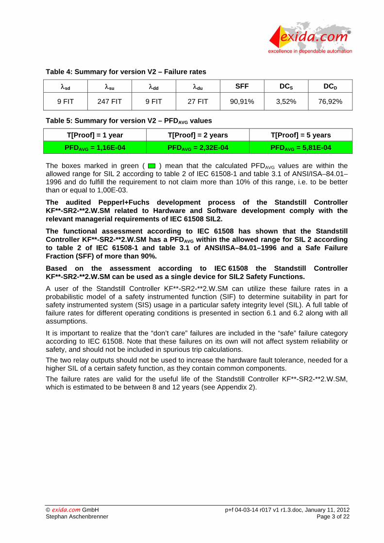
Table 4: Summary for version V2 – Failure rates
sd su dd du SFF DCS DCD
9 FIT 247 FIT 9 FIT 27 FIT 90,91% 3,52% 76,92%
Table 5: Summary for version V2 – PFDAVG values
T[Proof] = 1 year T[Proof] = 2 years T[Proof] = 5 years
PFDAVG = 1,16E-04 PFDAVG = 2,32E-04 PFDAVG = 5,81E-04
The boxes marked in green ( ) mean that the calculated PFDAVG values are within the allowed range for SIL 2 according to table 2 of IEC 61508-1 and table 3.1 of ANSI/ISA–84.01–1996 and do fulfill the requirement to not claim more than 10% of this range, i.e. to be better than or equal to 1,00E-03.
The audited Pepperl+Fuchs development process of the Standstill Controller KF**-SR2-**2.W.SM related to Hardware and Software development comply with the relevant managerial requirements of IEC 61508 SIL2.
The functional assessment according to IEC 61508 has shown that the Standstill Controller KF**-SR2-**2.W.SM has a PFDAVG within the allowed range for SIL 2 according to table 2 of IEC 61508-1 and table 3.1 of ANSI/ISA–84.01–1996 and a Safe Failure Fraction (SFF) of more than 90%.
Based on the assessment according to IEC 61508 the Standstill Controller KF**-SR2-**2.W.SM can be used as a single device for SIL2 Safety Functions.
A user of the Standstill Controller KF**-SR2-**2.W.SM can utilize these failure rates in a probabilistic model of a safety instrumented function (SIF) to determine suitability in part for safety instrumented system (SIS) usage in a particular safety integrity level (SIL). A full table of failure rates for different operating conditions is presented in section 6.1 and 6.2 along with all assumptions.
It is important to realize that the “don’t care” failures are included in the “safe” failure category according to IEC 61508. Note that these failures on its own will not affect system reliability or safety, and should not be included in spurious trip calculations.
The two relay outputs should not be used to increase the hardware fault tolerance, needed for a higher SIL of a certain safety function, as they contain common components.
The failure rates are valid for the useful life of the Standstill Controller KF**-SR2-**2.W.SM, which is estimated to be between 8 and 12 years (see Appendix 2).

© exida.com GmbH p+f 04-03-14 r017 v1 r1.3.doc, January 11, 2012 Stephan Aschenbrenner Page 4 of 22
Table of Contents
Management summary .................................................................................................... 2
1 Purpose and Scope ................................................................................................... 5
2 Project management .................................................................................................. 6
2.1 exida.com ....................................................................................................... 6
2.2 Roles of the parties involved ............................................................................ 6
2.3 Standards / Literature used ............................................................................. 6
2.4 Reference documents ...................................................................................... 7
2.4.1 Documentation provided by the customer ................................................ 7
2.4.2 Documentation generated by exida.com .................................................. 8
3 Description of the analyzed module ........................................................................... 9
3.1 Standstill Controller KF**-SR2-**2.W.SM ........................................................ 9
4 Results of the assessment of the fault avoidance measures ................................... 11
5 Failure Modes, Effects, and Diagnostics Analysis ................................................... 13
5.1 Description of the failure categories ............................................................... 13
5.2 Methodology – FMEDA, Failure rates ............................................................ 14
5.2.1 FMEDA ................................................................................................... 14
5.2.2 Failure rates ............................................................................................ 14
5.2.3 Assumption ............................................................................................. 14
6 Results of the hardware assessment ....................................................................... 15
6.1 Version V1 ..................................................................................................... 16
6.2 Version V2 ..................................................................................................... 17
7 Terms and Definitions .............................................................................................. 18
8 Status of the document ............................................................................................ 19
8.1 Liability ........................................................................................................... 19
8.2 Releases ........................................................................................................ 19
8.3 Release Signatures ....................................................................................... 19
Appendix 1: Possibilities to reveal dangerous undetected faults during the proof test .. 20
Appendix 1.1: Possible proof test to detect dangerous undetected faults ............... 21
Appendix 2: Impact of lifetime of critical components on the failure rate ....................... 22

© exida.com GmbH p+f 04-03-14 r017 v1 r1.3.doc, January 11, 2012 Stephan Aschenbrenner Page 5 of 22
1 Purpose and Scope Generally three options exist when doing an assessment of sensors, interfaces and/or final elements.
Option 1: Hardware assessment according to IEC 61508
Option 1 is a hardware assessment by exida.com according to the relevant functional safety standard(s) like DIN V VDE 0801, IEC 61508 or EN 954-1. The hardware assessment consists of a FMEDA to determine the fault behavior and the failure rates of the device, which are then used to calculate the Safe Failure Fraction (SFF) and the average Probability of Failure on Demand (PFDAVG).
This option for pre-existing hardware devices shall provide the safety instrumentation engineer with the required failure data as per IEC 61508 / IEC 61511 and does not consist of an assessment of the software development process
Option 2: Hardware assessment with proven-in-use consideration according to IEC 61508 / IEC 61511
Option 2 is an assessment by exida.com according to the relevant functional safety standard(s) like DIN V VDE 0801, IEC 61508 or EN 954-1. The hardware assessment consists of a FMEDA to determine the fault behavior and the failure rates of the device, which are then used to calculate the Safe Failure Fraction (SFF) and the average Probability of Failure on Demand (PFDAVG). In addition this option consists of an assessment of the proven-in-use documentation of the device and its software including the modification process.
This option for pre-existing programmable electronic devices shall provide the safety instrumentation engineer with the required failure data as per IEC 61508 / IEC 61511 and justify the reduced fault tolerance requirements of IEC 61511 for sensors, final elements and other PE field devices.
Option 3: Full assessment according to IEC 61508
Option 3 is a full assessment by exida.com according to the relevant application standard(s) like IEC 61511 or EN 298 and the necessary functional safety standard(s) like DIN V VDE 0801, IEC 61508 or EN 954-1. The full assessment extends option 1 by an assessment of all fault avoidance and fault control measures during hardware and software development.
This option is most suitable for newly developed software based field devices and programmable controllers to demonstrate full compliance with IEC 61508 to the end-user.
This assessment shall be done according to option 3.
This document shall describe the results of the assessment carried out on the Standstill Controller KF**-SR2-**2.W.SM with software version 2v0. The purpose of the assessment is to investigate the compliance of the processes, procedures and techniques as implemented with the managerial IEC 61508-1, -2 and -3 requirements for SIL2. Table 1 gives an overview of the different configurations of the considered device.
It shall be assessed whether this device meets the requirements for SIL 2 sub-systems according to IEC 61508. It does not consider any calculations necessary for proving intrinsic safety.

© exida.com GmbH p+f 04-03-14 r017 v1 r1.3.doc, January 11, 2012 Stephan Aschenbrenner Page 6 of 22
2 Project management
2.1 exida.com
exida.com is one of the world’s leading knowledge companies specializing in automation system safety and availability with over 100 years of cumulative experience in functional safety. Founded by several of the world’s top reliability and safety experts from assessment organizations like TUV and manufacturers, exida.com is a partnership with offices around the world. exida.com offers training, coaching, project oriented consulting services, internet based safety engineering tools, detail product assurance and certification analysis and a collection of on-line safety and reliability resources. exida.com maintains a comprehensive failure rate and failure mode database on process equipment.
2.2 Roles of the parties involved
Pepperl+Fuchs Manufacturer of the Standstill Controller KF**-SR2-**2.W.SM.
exida.com Performed the IEC 61508 assessment according to option 3 (see section 1).
Pepperl+Fuchs GmbH contracted exida.com in April 2004 with the IEC 61508 assessment of the above mentioned device.
2.3 Standards / Literature used
The services delivered by exida.com were performed based on the following standards / literature.
N1 IEC 61508 (Parts 1-7):2000 Functional Safety of Electrical/Electronic/Programmable Electronic Safety-Related Systems
N2 ISBN: 0471133019 John Wiley & Sons
Electronic Components: Selection and Application Guidelines by Victor Meeldijk
N3 FMD-91, RAC 1991 Failure Mode / Mechanism Distributions
N4 FMD-97, RAC 1997 Failure Mode / Mechanism Distributions
N5 SN 29500 Failure rates of components

© exida.com GmbH p+f 04-03-14 r017 v1 r1.3.doc, January 11, 2012 Stephan Aschenbrenner Page 7 of 22
2.4 Reference documents
2.4.1 Documentation provided by the customer
[D1] 01-6741 of 07.06.04 Circuit diagram
[D2] Product No. 132964 / 802538 Bill of material for KFD2-SR2-EX2.W.SM
[D3] Product No. 132965 / 802539 Bill of material for KFD2-SR2-2.W.SM
[D4] Version 0 of 05.06.02 P02.05 Produktpflege.pps
[D5] Version 0 of 05.04.02 P08.01 Abwicklung von Produktrücklieferungen-0.ppt
[D6] 12.02.02 P0205010202 NCDRWorkflow.ppt
[D7] 130428A.pdf Safety case against the technical requirements of IEC 61508
[D8] 130429.pdf P+F development process including arguments on the fulfillment of the requirements (safety case)
[D9] Pflichtenheft_Stillstandswächter_Index_F.pdf
Requirements Specification
[D10] A02-03-010.pdf Coding guideline
[D11] Stillstandswächter2v0.pdf Description, flow-charts of the firmware
[D12] 18-30481B Source files of the firmware
[D13] 1830481B.pdf Software release information 2v0
[D14] 13-0421.pdf System tests
[D15] 13-0422.pdf Software white-box tests
[D16] PRDE-2805A.pdf Validation test for product qualification
[D17] PRDE-2950B.pdf Test report electromechanical and environmental
[D18] PRDE-2922A.pdf EMC test report
[D19] PRDE-2930A.pdf Immunity tests according to NE21
[D20] 084378A.pdf Test procedure Ex devices
[D21] 084379B.pdf Test procedure Non Ex devices
[D22] 130453.pdf Results of the fault insertion tests
[D23] 300551.pdf Safety Manual
[D24] 300552.pdf Verification Plan
[D25] 300553.pdf Results of the thermography as de-rating analysis
[D26] Restrict.txt Limitations and recommendations for the use of the compiler MPLAB-C Version 1.21
[D27] Review Hardware_6_feb_03.pdf Results of the review of the hardware and the specification
[D28] Review_Firmwarevalidierung.pdf Results of the review of the firmware
[D29] SSWCodetest_ENNOS_1.pdf Review of the specification against the flowcharts and the source code

© exida.com GmbH p+f 04-03-14 r017 v1 r1.3.doc, January 11, 2012 Stephan Aschenbrenner Page 8 of 22
2.4.2 Documentation generated by exida.com
[R1] FMEDA V5 Conf 1 V1 R1.1.xls of 15.04.05
[R2] FMEDA V5 Conf 2 V1 R1.1 ohne LB-SC detection.xls of 15.04.05
[R3] FMEDA V5 Conf 5 V1 R1.1.xls of 15.04.05
[R4] Assessment Plan V1 R1.0.doc
[R5] Minutes of meeting April 13th to 15th 2004 (Besprechungsbericht.doc)
[R6] FIT definition for FMEDA V5 Conf 2 V1 R1.0.pdf (Definition of fault insertion tests)
[R7] Objectives of IEC 61508 V1 R1.0.pdf
[R8] Kommentare zum SIL 2 Assessment.doc; email of 18.06.04 (Assessment comments)
[R9] Safety Manual Checklist V1 R1.0 of 30.06.04

© exida.com GmbH p+f 04-03-14 r017 v1 r1.3.doc, January 11, 2012 Stephan Aschenbrenner Page 9 of 22
3 Description of the analyzed module
3.1 Standstill Controller KF**-SR2-**2.W.SM
The Standstill Controller KF**-SR2-**2.W.SM is a Type B component with a hardware fault tolerance of 0.
By means of a DIP-switch the functions standstill controller with start-up override (S3=I) or standstill controller with rotation direction monitoring (S3=II) can be selected.
Output I is the safety-related output.
Standstill controller with start-up override (S3 = I)
The standstill monitor with start-up override switches output I in a de-energized state (passive), output II in an energized state (active) when the input frequency drops below the trip-point, adjusted by means of the DIP-switches S1 and S2. Input I is used for frequency monitoring of rising edges.
Signal transmitters can be sensors in accordance with DIN EN 60947-5-6 (NAMUR) or 3 wire sensors with external power supply.
Via input II a start-up override can be activated. The duration of a start-up override can be selected by means of a bridge (trigger) or by means of an external trigger signal of either 5 or 20 seconds. During the start-up override „no standstill“ detection is processed.
Standstill controller with rotation direction monitoring (S3 = II)
The device offers a stand still monitoring with rotation direction monitoring but without start-up override. The trip-points are identical to the standstill monitor with start-up override. At input II a signal with a phase shift of 90 ° to input I has to be applied; in this context a minimum signal overlapping should be ensured.
Signal transmitters at input I and input II can be sensors in accordance with DIN EN 60947-5-6 (NAMUR), mechanical contacts or 3 wire sensors with external power supply.

© exida.com GmbH p+f 04-03-14 r017 v1 r1.3.doc, January 11, 2012 Stephan Aschenbrenner Page 10 of 22
Output I can be used for standstill signaling and switches into the de-energized state (passive) in case of a standstill. The active state of output II corresponds to 'clockwise rotation’ whereas the passive state of output II corresponds to ‘counter clockwise’ rotation. If no signal overlapping is detected, output II switches into the de-energized state (passive). As already mentioned the frequencies at both input channels must be the same with a phase shift of 90°. If the input pulses at one input, either I or II, are missing (sensor misadjusted for example) output II (for direction monitoring) switches to a de-energized (passive) state. The standstill monitoring (output I) will work as long as there are pulses at input I or input II available.
If a lead fault occurs both relays will switch to a de-energized (passive) state and the red flashing LEDs will indicate a hardware fault.
Figure 1: Block diagram of the Standstill Controller KFD2-SR2-Ex2.W.SM

© exida.com GmbH p+f 04-03-14 r017 v1 r1.3.doc, January 11, 2012 Stephan Aschenbrenner Page 11 of 22
4 Results of the assessment of the fault avoidance measures
exida.com assessed the development process used by Pepperl+Fuchs for this development against the objectives of IEC 61508 parts 1 to 3. The results of this assessment are documented in [R7]. All objectives have been sufficiently considered in the Pepperl+Fuchs development process for the Standstill Controller KF**-SR2-**2.W.SM.
Additionally exida.com assessed the safety case (see [D7]) prepared by Pepperl+Fuchs against the technical requirements of IEC 61508. The safety case demonstrated the fulfillment of the technical requirements of IEC 61508.
exida.com defined fault insertion tests (see [R6]) and verified together with Pepperl+Fuchs the correctness of the FMEDA and the corresponding safety parameters (see [D22]).
The assessment investigated the compliance with IEC 61508 of the processes, procedures and techniques as implemented for the Pepperl+Fuchs Standstill Controller KF**-SR2-**2.W.SM development.
The investigation was executed using subsets of the IEC 61508 requirements tailored to the work scope of the development team. The result of the assessment can be summarized by the following observations:
The audited Pepperl+Fuchs development process of the Standstill Controller KF**-SR2-**2.W.SM related to Hardware and Software development comply with the relevant managerial requirements of IEC 61508 SIL2.
The Functional Safety Management assessment was driven by the objectives of IEC 61508. A detailed Functional Safety Management audit was not carried out because the development team is very small and the hardware was already developed 5 years ago. Thus the assessment concentrated on the IEC 61508 objectives and document reviews. The following IEC 61508 objectives were subject to detailed assessment:
(1) FSM planning
The FSM-Plan ([D8]) defines for all the different work steps the required input and output documents. Phases are sorted in the subchapters of the FSM-Plan. Document [D9] defines the different Roles of people.
(2) Configuration management
All version information for hardware and software is stored in the EDM system. Previous releases can always be reviewed. Newer versions get a new index of the same document number.
(3) Change and modification management
A modification procedure is defined in section 1.3 of the FSM-Plan ([D8]). In addition the Peperl+Fuchs process description describes in section P02.05.2.1 the required steps for carrying out a modification.
(4) Hardware design process, techniques and documentation
The hardware of the Standstill Controller KF**-SR2-**2.W.SM is almost identical to the hardware of the KFD2-SR2-Ex2.W which is already used for about 5 years. This means that for the hardware sufficient field experience exist.

© exida.com GmbH p+f 04-03-14 r017 v1 r1.3.doc, January 11, 2012 Stephan Aschenbrenner Page 12 of 22
(5) Software design process, techniques and documentation
The software of the Standstill Controller KF**-SR2-**2.W.SM is not very complex which means that not all techniques/measures recommended for SIL 2 have been considered. However, arguments have been given by Pepperl+Fuchs for all technical requirements of IEC 61508 (see [D7]).
(6) Tools and Languages
The FSM-Plan ([D8]) shows in chapter 4.4.4 the list of tools used in relation to the different areas of development (generic, hardware, software)
(7) Hardware architecture and probabilistic
As required by IEC 61508 FMEDA, probabilistic calculations and fault insertion tests have been carried out for the Standstill Controller KF**-SR2-**2.W.SM. The results are documented in sections 5 and 6.
(8) System related V&V activities including documentation, verification planning, integration test and requirements tracking
The FSM-Plan ([D8]) defines more or less the required verification tests. Tests are also documented in [D16], [D18] and [D19]. Blackbox-tests are documented in [D14] and [D17].
(9) System Validation including Hardware and Software Validation
All validation activities are documented in the system validation tests ([D14]) and the software validation tests ([D15]). All system validation tests are linked to the requirements in [D9].
(10) Safety Manual
Several versions of the safety manual [D23] were inspected. The final version is considered to be in compliance with the requirements of IEC 61508.

© exida.com GmbH p+f 04-03-14 r017 v1 r1.3.doc, January 11, 2012 Stephan Aschenbrenner Page 13 of 22
5 Failure Modes, Effects, and Diagnostics Analysis
The Failure Modes, Effects, and Diagnostic Analysis was done together with Pepperl+Fuchs GmbH and is documented in [R1] to [R3].
5.1 Description of the failure categories
In order to judge the failure behavior of the Standstill Controller KF**-SR2-**2.W.SM, the following definitions for the failure of the product were considered.
Fail-Safe State The fail-safe state is defined as the output (K1.1) being de-energized. This corresponds to an input signal (frequency) at terminal 1-2-3 above the trip point.
Fail Safe Failure that causes the module / (sub)system to go to the defined fail-safe state without a demand from the process. Safe failures are divided into safe detected (SD) and safe undetected (SU) failures.
Fail Dangerous Failure that does not respond to a demand from the process (i.e. being unable to go to the defined fail-safe state).
Fail Dangerous Undetected Failure that is dangerous and that is not being diagnosed by internal diagnostics.
Fail Dangerous Detected Failure that is dangerous but is detected by internal diagnostics (These failures may be converted to the selected fail-safe state).
Fail No Effect Failure of a component that is part of the safety function but that has no effect on the safety function. For the calculation of the SFF it is treated like a safe undetected failure.
Not part Failures of a component which is not part of the safety function but part of the circuit diagram and is listed for completeness. When calculating the SFF this failure mode is not taken into account. It is also not part of the total failure rate.
The “No Effect” failures are provided for those who wish to do reliability modeling more detailed than required by IEC 61508. In IEC 61508 the “No Effect” failures are defined as safe undetected failures even though they will not cause the safety function to go to a safe state. Therefore they need to be considered in the Safe Failure Fraction calculation.

© exida.com GmbH p+f 04-03-14 r017 v1 r1.3.doc, January 11, 2012 Stephan Aschenbrenner Page 14 of 22
5.2 Methodology – FMEDA, Failure rates
5.2.1 FMEDA
A Failure Modes and Effects Analysis (FMEA) is a systematic way to identify and evaluate the effects of different component failure modes, to determine what could eliminate or reduce the chance of failure, and to document the system in consideration.
An FMEDA (Failure Mode Effect and Diagnostic Analysis) is an FMEA extension. It combines standard FMEA techniques with extension to identify online diagnostics techniques and the failure modes relevant to safety instrumented system design. It is a technique recommended to generate failure rates for each important category (safe detected, safe undetected, dangerous detected, dangerous undetected, fail high, fail low) in the safety models. The format for the FMEDA is an extension of the standard FMEA format from MIL STD 1629A, Failure Modes and Effects Analysis.
5.2.2 Failure rates
The failure rate data used by exida.com in this FMEDA are the basic failure rates from the Siemens SN 29500 failure rate database. The rates were chosen in a way that is appropriate for safety integrity level verification calculations. The rates were chosen to match operating stress conditions typical of an industrial field environment similar to IEC 645-1, class C. It is expected that the actual number of field failures will be less than the number predicted by these failure rates.
The user of these numbers is responsible for determining their applicability to any particular environment. Accurate plant specific data may be used for this purpose. If a user has data collected from a good proof test reporting system that indicates higher failure rates, the higher numbers shall be used. Some industrial plant sites have high levels of stress. Under those conditions the failure rate data is adjusted to a higher value to account for the specific conditions of the plant.
5.2.3 Assumption
The following assumptions have been made during the FMEDA:
Failure rates are constant, wear out mechanisms are not included.
Propagation of failures is not relevant.
The repair time after a safe failure is 8 hours.
The test time of the logic solver to react on a dangerous detected failure is 1 hour.
The stress levels are average for an industrial environment and can be compared to the Ground Fixed classification of MIL-HNBK-217F. Alternatively, the assumed environment is similar to:
o IEC 645-1, Class C (sheltered location) with temperature limits within the manufacturer’s rating and an average temperature over a long period of time of 40ºC. Humidity levels are assumed within manufacturer’s rating.
All modules are operated in the low demand mode of operation.
External power supply failure rates are not included.
Sensors are not included in the failure rates listed.
Output I is used as the safety-related output.

© exida.com GmbH p+f 04-03-14 r017 v1 r1.3.doc, January 11, 2012 Stephan Aschenbrenner Page 15 of 22
6 Results of the hardware assessment
exida.com did the FMEDAs together with Pepperl+Fuchs.
For the calculation of the Safe Failure Fraction (SFF) the following has to be noted:
total consists of the sum of all component failure rates. This means:
total = safe + dangerous + don’t care + annunciation.
SFF = 1 – du / total
For the FMEDAs failure modes and distributions were used based on information gained from [N3] to [N5].
For the calculation of the PFDAVG the following Markov model for a 1oo1D system was used. As after a complete proof test all states are going back to the OK state no proof test rate is shown in the Markov models but included in the calculation.
The proof test time was changed using the Microsoft® Excel 2000 based FMEDA tool of exida.com as a simulation tool. The results are documented in the following sections.
Abbreviations:
du The system has failed dangerous undetected
dd The system has failed dangerous detected
s The system has failed safe
du Failure rate of dangerous undetected failures
dd Failure rate of dangerous detected failures
s Failure rate of safe failures
TTest Test time
Test Test rate (1 / TTest)
TRepair Repair time
Repair Repair rate (1 / TRepair)
Figure 2: Markov model for a 1oo1D structure
du
s
du dd
ok
s
dd
Repair
Test
© exida.com GmbH p+f 04-03-14 r017 v1 r1.3.doc, January 11, 2012 Stephan Aschenbrenner Page 16 of 22
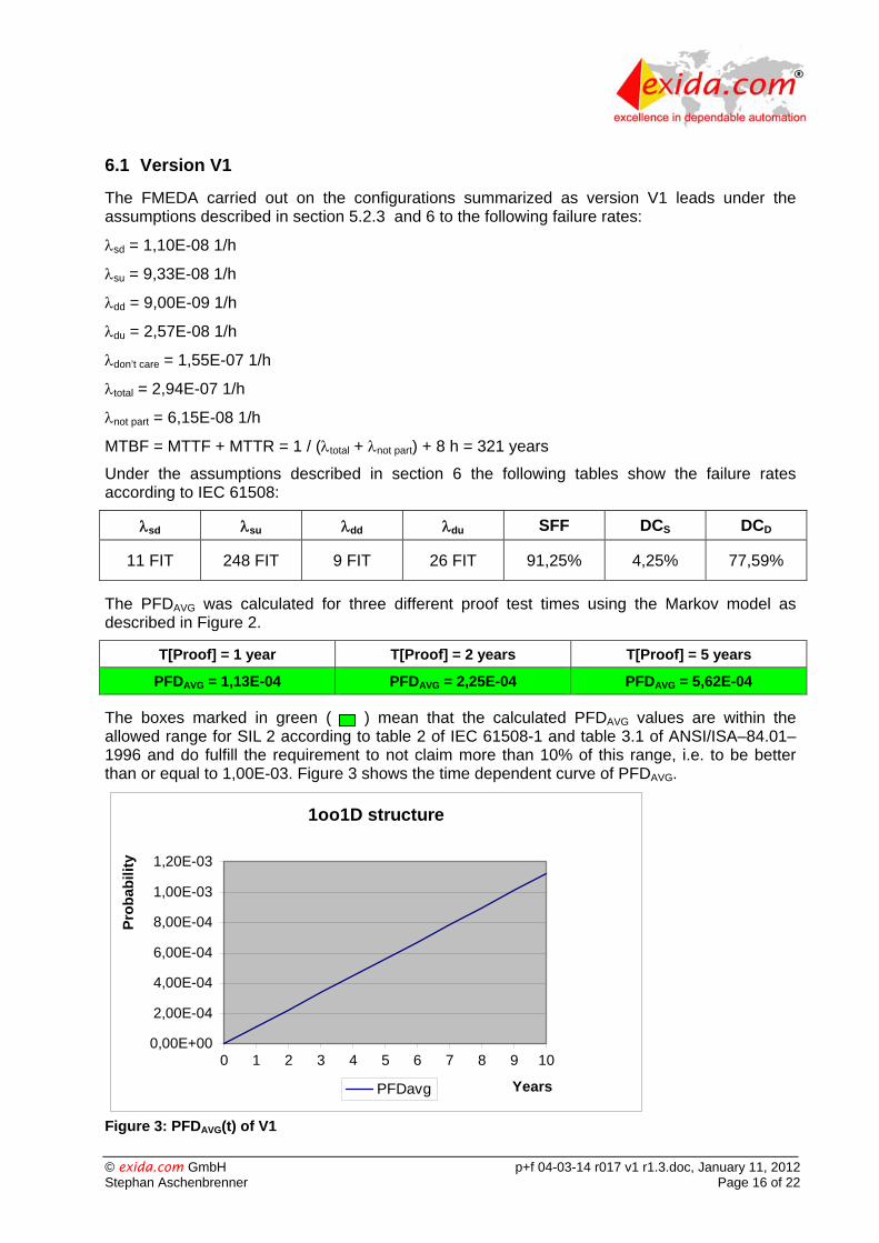
6.1 Version V1
The FMEDA carried out on the configurations summarized as version V1 leads under the assumptions described in section 5.2.3 and 6 to the following failure rates:
sd = 1,10E-08 1/h
su = 9,33E-08 1/h
dd = 9,00E-09 1/h
du = 2,57E-08 1/h
don’t care = 1,55E-07 1/h
total = 2,94E-07 1/h
not part = 6,15E-08 1/h
MTBF = MTTF + MTTR = 1 / (total + not part) + 8 h = 321 years
Under the assumptions described in section 6 the following tables show the failure rates according to IEC 61508:
sd su dd du SFF DCS DCD
11 FIT 248 FIT 9 FIT 26 FIT 91,25% 4,25% 77,59%
The PFDAVG was calculated for three different proof test times using the Markov model as described in Figure 2.
T[Proof] = 1 year T[Proof] = 2 years T[Proof] = 5 years
PFDAVG = 1,13E-04 PFDAVG = 2,25E-04 PFDAVG = 5,62E-04
The boxes marked in green ( ) mean that the calculated PFDAVG values are within the allowed range for SIL 2 according to table 2 of IEC 61508-1 and table 3.1 of ANSI/ISA–84.01–1996 and do fulfill the requirement to not claim more than 10% of this range, i.e. to be better than or equal to 1,00E-03. Figure 3 shows the time dependent curve of PFDAVG.
1oo1D structure
0,00E+00
2,00E-04
4,00E-04
6,00E-04
8,00E-04
1,00E-03
1,20E-03
0 1 2 3 4 5 6 7 8 9 10
Years
Pro
bab
ility
PFDavg
Figure 3: PFDAVG(t) of V1

© exida.com GmbH p+f 04-03-14 r017 v1 r1.3.doc, January 11, 2012 Stephan Aschenbrenner Page 17 of 22
6.2 Version V2
The FMEDA carried out on the configurations summarized as version V2 leads under the assumptions described in section 5.2.3 and 6 to the following failure rates:
sd = 9,00E-09 1/h
su = 9,33E-08 1/h
dd = 9,00E-09 1/h
du = 2,65E-08 1/h
don’t care = 1,54E-07 1/h
total = 2,92E-07 1/h
not part = 6,33E-08 1/h
MTBF = MTTF + MTTR = 1 / (total + not part) + 8 h = 321 years
Under the assumptions described in section 6 the following tables show the failure rates according to IEC 61508:
sd su dd du SFF DCS DCD
9 FIT 247 FIT 9 FIT 27 FIT 90,91% 3,52% 76,92%
The PFDAVG was calculated for three different proof test times using the Markov model as described in Figure 2.
T[Proof] = 1 year T[Proof] = 2 years T[Proof] = 5 years
PFDAVG = 1,16E-04 PFDAVG = 2,32E-04 PFDAVG = 5,81E-04
The boxes marked in green ( ) mean that the calculated PFDAVG values are within the allowed range for SIL 2 according to table 2 of IEC 61508-1 and table 3.1 of ANSI/ISA–84.01–1996 and do fulfill the requirement to not claim more than 10% of this range, i.e. to be better than or equal to 1,00E-03. Figure 3 shows the time dependent curve of PFDAVG.
1oo1D structure
0,00E+00
2,00E-04
4,00E-04
6,00E-04
8,00E-04
1,00E-03
1,20E-03
1,40E-03
0 1 2 3 4 5 6 7 8 9 10
Years
Pro
bab
ility
PFDavg
Figure 4: PFDAVG(t) of V2

© exida.com GmbH p+f 04-03-14 r017 v1 r1.3.doc, January 11, 2012 Stephan Aschenbrenner Page 18 of 22
7 Terms and Definitions DCS Diagnostic Coverage of safe failures (DCS = sd / (sd + su)
DCD Diagnostic Coverage of dangerous failures (DCD = dd / (dd + du)
FIT Failure In Time (1x10⁻⁹ failures per hour)
FMEDA Failure Mode Effect and Diagnostic Analysis
HFT Hardware Fault Tolerance
Low demand mode Mode, where the frequency of demands for operation made on a safety-related system is no greater than one per year and no greater than twice the proof test frequency.
PFDAVG Average Probability of Failure on Demand
SFF Safe Failure Fraction summarizes the fraction of failures, which lead to a safe state and the fraction of failures which will be detected by diagnostic measures and lead to a defined safety action.
SIF Safety Instrumented Function
SIL Safety Integrity Level
Type B component “Complex” component (using micro controllers or programmable logic); for details see 7.4.3.1.3 of IEC 61508-2
T[Proof] Proof Test Interval

© exida.com GmbH p+f 04-03-14 r017 v1 r1.3.doc, January 11, 2012 Stephan Aschenbrenner Page 19 of 22
8 Status of the document
8.1 Liability
exida.com prepares FMEDA reports based on methods advocated in International standards. Failure rates are obtained from a collection of industrial databases. exida.com accepts no liability whatsoever for the use of these numbers or for the correctness of the standards on which the general calculation methods are based.
8.2 Releases
Version: V1
Revision: R1.3
Version History: V0, R1.0: Initial version, June 17, 2004
V0, R1.1: Additional documentation added, June 30, 2004
V1, R1.0: Review comments integrated, July 25, 2004
V1, R1.1: Review comments integrated, August 11, 2004
V1, R1.2: Updated schematics and FMEDAs added, April 15, 2005
V1, R1.3: Failure rate dd corrected; January 11, 2012
Authors: Stephan Aschenbrenner
Review: V0, R1.0: Peter Müller (exida), June 29, 2004
Harald Eschelbach (P+F), July 14, 2004
V0, R1.1: Rachel Amkreutz (exida), July 15, 2004
V1, R1.0: Rachel Amkreutz (exida), August 10, 2004
Release status: Released to Pepperl+Fuchs
8.3 Release Signatures
Dipl.-Ing. (Univ.) Stephan Aschenbrenner, Partner
Dipl.-Ing. (Univ.) Rainer Faller, Principal Partner

© exida.com GmbH p+f 04-03-14 r017 v1 r1.3.doc, January 11, 2012 Stephan Aschenbrenner Page 20 of 22
Appendix 1: Possibilities to reveal dangerous undetected faults during the proof test
According to section 7.4.3.2.2 f) of IEC 61508-2 proof tests shall be undertaken to reveal dangerous faults which are undetected by diagnostic tests.
This means that it is necessary to specify how dangerous undetected faults which have been noted during the FMEDA can be detected during proof testing.
Table 6 and Table 7 show a sensitivity analysis of the ten most critical dangerous undetected faults and indicates how these faults can be detected during proof testing.
Appendix 1 and Appendix 2 should be considered when writing the safety manual as they contain important safety related information.
Table 6: Sensitivity Analysis of “du” failures of version V1
Component % of total du Detection through
IC61 - CPU and additional electronics 23,36% 100% functional test with monitoring of the output signal
IC31 19,46% 100% functional test with monitoring of the output signal
IC61 - internal RAM 15,57% 100% functional test with monitoring of the output signal
G61 7,79% 100% functional test with monitoring of the output signal
P3.1 6,42% 100% functional test with monitoring of the output signal
K1.1 5,06% 100% functional test with monitoring of the output signal
C51.1 3,89% 100% functional test with monitoring of the output signal
C51.2 3,89% 100% functional test with monitoring of the output signal
C52 3,89% 100% functional test with monitoring of the output signal
IC61 - internal ROM 3,89% 100% functional test with monitoring of the output signal

© exida.com GmbH p+f 04-03-14 r017 v1 r1.3.doc, January 11, 2012 Stephan Aschenbrenner Page 21 of 22
Table 7: Sensitivity Analysis of “du” failures of version V2
Component % of total du Detection through
IC61 - CPU and additional electronics 22,62% 100% functional test with monitoring of the output signal
IC31 18,85% 100% functional test with monitoring of the output signal
IC61 - internal RAM 15,08% 100% functional test with monitoring of the output signal
G61 7,54% 100% functional test with monitoring of the output signal
P3.1 6,22% 100% functional test with monitoring of the output signal
K1.1 4,90% 100% functional test with monitoring of the output signal
C51.1 3,77% 100% functional test with monitoring of the output signal
C51.2 3,77% 100% functional test with monitoring of the output signal
C52 3,77% 100% functional test with monitoring of the output signal
IC61 - internal ROM 3,77% 100% functional test with monitoring of the output signal
Appendix 1.1: Possible proof test to detect dangerous undetected faults
The proof test consists of the following steps, as described in Table 8.
Table 8 Steps for Proof Test
Step Action
1 Take appropriate action to avoid a false trip
2 Provide an input signal (frequency) at terminal 1-2-3 above the trip point to the Standstill Controller KF**-SR2-**2.W.SM to open the output (K1.1) and verify that the output is open.
3 Restore the loop to full operation
4 Restore normal operation
This test will detect possible “du” failures in the Standstill Controller KF**-SR2-**2.W.SM.

© exida.com GmbH p+f 04-03-14 r017 v1 r1.3.doc, January 11, 2012 Stephan Aschenbrenner Page 22 of 22
Appendix 2: Impact of lifetime of critical components on the failure rate
Although a constant failure rate is assumed by the probabilistic estimation method (see section 5.2.3) this only applies provided that the useful lifetime of components is not exceeded. Beyond their useful lifetime, the result of the probabilistic calculation method is meaningless as the probability of failure significantly increases with time. The useful lifetime is highly dependent on the component itself and its operating conditions – temperature in particular (for example, electrolyte capacitors can be very sensitive).
This assumption of a constant failure rate is based on the bathtub curve, which shows the typical behavior for electronic components.
Therefore it is obvious that the PFDAVG calculation is only valid for components that have this constant domain and that the validity of the calculation is limited to the useful lifetime of each component.
It is assumed that early failures are detected to a huge percentage during the installation period and therefore the assumption of a constant failure rate during the useful lifetime is valid.
Table 9 shows which electrolytic capacitors are contributing to the dangerous undetected failure rate and therefore to the PFDAVG calculation and what their estimated useful lifetime is.
Table 9: Useful lifetime of electrolytic capacitors contributing to du
Type Name Useful life at 40°C Capacitor (electrolytic) - Tantalum electrolytic, solid electrolyte
C1.1 Appr. 500 000 hours
The only limiting factor is the Tantalum electrolytic capacitor with regard to the useful lifetime of the system, which has a useful lifetime of about 57 years.
However, according to section 7.4.7.4 of IEC 61508-2, a useful lifetime, based on experience, should be assumed. According to section 7.4.7.4 note 3 of IEC 61508-2 experience has shown that the useful lifetime often lies within a range of 8 to 12 years.