(pfaff) ~~~-- (fl) 335 - uwe grosse...
TRANSCRIPT

c -
J -------=~~~-- (Fl)
(PFAFF) 335
Single-Needle, Cylinder-Bed,
Unison-Feed Sewing Machine
Instruction Book
IG ~ M ·PFAFF A G · KAISERS LAUTER N BRA C H
)
)
Foreword
The operational instructions given in this booklet pertain not only to the ordinary Pfaff 335-17 binding machine, but also to all other subclass varieties.
The individual subc lasses are fitted to suit different operational requirements. The vari-ous subclass organizations differ only in the type of rigid or swing-away binder or tape guide mounted on the feed-synchronized attachment bracket.
An except ion are the Pfaff 335-9, -09, and -09-33 which are specially designed for port-folio work and have a rigid tape guide mounted on the cylinder arm.
The Pfaff 335-332 X 251 occupies a special position in that it is fitted with upper feed acceleration control rather than ordinary unison feed.
The operating instructions for this machine are also contained in this Instruction Book.
G. M. PFAFF AG
3

1. General
)1. The machine is fitted with sleeve take-up and a bevel-gear-driven rotary hook, mov-ing counter-clockwise.
2. It makes down to 51/2 stitches per inch and, depending on the material to be sewn, may be operated at speeds ranging from 1,400 to 2,500 s.p.m.
3. To avoid trouble in the mechanism, run the machine at about 75 per cent of its top speed until the parts which are in movable contact have become thoroughly glazed by their action upon each other. This should normally be the case after about two weeks' constant daily use.
4. The tape is unreeled by the motion of both the feed dog and the feed-synchronized binder so that the binding is smoothly and evenly applied even around curves.
All machines are reg ularly equi pped with a fixed pulley which is cast in one with the balance wheel. If desired, however, these machines can be supplied with a disengage-able pulley.
Such machines are dispatched with the sewing mechanism disengaged. To engage this mechanism for sewing, hold the balance wheel steady with your left hand and turn the large lock nut over from you.
2. Fundamentals of Machine Operation
Before you put the machine in operation for the first time, carefu ll y remove all dust ) which has accumulat.ed in transit and oil the machine thoroughly (see Chapter 3) .
Oil the machine only with Pfaff sewing machine oil which is non-resinous and acid-free.
Never run a threaded machine unless you have fabric under the presser foot.
Before you start sewing, Jay both threads back under the presser foot.
To prevent thread jamming, hold both thread ends until the machine has made a few stitches.
Do not pull the material while stitching; the machine will feed the fabric automatically.
Use needles of the correct system only (see Chapter 10) .
Never use ru sty needles.
Use high-grade threads only .
. Always bring the take-up lever to its highest point before you remove the material.
3. Cleaning and Lubricating the Machine
Take a c lean rag and remove the grease from all nickel-plated and polished parts of the machine. Rinse the sewing hook with cleaning f luid and apply a few drops of thi s flu id to all oiling points marked in Figs. 1, 2, 3 and 4. Place a piece of fabric under the pres-ser foot, raise the presser bar and run the machine a short while until all grease is washed ou t. Wipe the machine dry and apply a drop of Pfaff sewing machine oil No. 280-1-120 122 to all points of fricti on.
)All points of friction shou ld be oiled twice a week. The sewing hook, however, should be oiled every day.
4

R 7812 .
Fig. 1
R 7760 -
) Fig. 2
5

R 7766
) Fig. 4
6
R 8014
Fig. 3
f.
(
1
(
f.
r t t t (
)
)
R 7770
Fig. 5
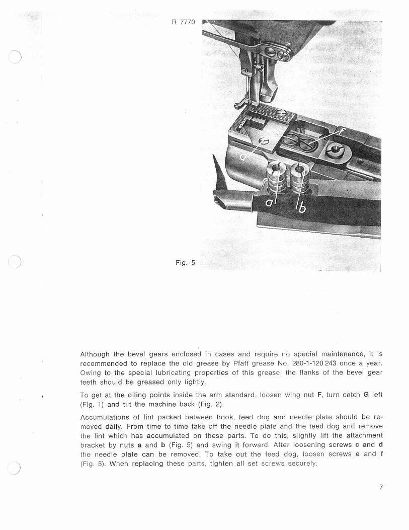
Although the bevel gears enclosed in cases and require no special maintenance, it is recommended to replace the o ld grease by Pfaff grease No. 280-1 -1 20 243 once a year. Owing to the spec ial lubricating properties of this grease, the flanks of the bevel gear teeth should be greased only lightly.
To get at the oiling points inside the arm standard , loosen wing nut F, turn catch G left (Fig. 1) and tilt the machine back (Fig. 2) .
Accumu lations of lint packed between hook, feed dog and needle plate should be re-moved daily. From time to time take off the needle plate and the feed dog and remove the lint which has accumulated on these parts. To do this, sl ightly lift the attachment bracket by nuts a and b (Fig. 5) and swing it forward. Afte r loosening screws c and d the needle plate can be removed. To take out the feed dog, loosen screws e and f (Fig. 5). When replacing t hese parts, tighten all set screws secu rely.
7

R 7894
Fig. 6
4. Winding the Bobbin
) Place the spool of thread on spool pin 1 (Fig. 6) and the bobbin on spind le 5. Pass the thread through eyelet 2, between tension discs 3, over pin 4, and pull it through the s lot in the bobbin. from the inside. Press in lever 6 until the bobbin winder pulley contacts the belt. Hold the end of the thread and slowly start the machine. Check to see that the bobbin winder pulley rotates clockwise, as indicated by an arrow in Fig. 7. The bobbin winder will stop automatically when the bobbin is full . The amount of thread to be wound on the bobbin is regulated by screw 7.
Turn it right for more thread; turn it left for less thread.
z
Fig. 7
8
I· v
t l
c c
5
F y
v 1-
L
t l
L t ~

)
)
If the thread should pile up at one end of the bobbin, adjust the position of the bobbin winder tension and the spool of thread sideways, as may be requi red. To do this, loosen the screw, ad just the tension bracket and tighten the screw again .
Check to see that the bobbin winder tension is set correctly. Turn the regulati ng nut clockwise for a tighter tension, or counter-clockwise for a looser tension .
5. Removing the Bobbin and ·Threading the Bobbin Case
Raise the needle bar to its highest position, open the cylinder arm cap, lift latch A with your left thumb and pull out the bobbin case with the bobbin (Fig. 8).
While you hold the bobbin case by its open latch, the bobbin can not fall out.
Hold the bobbin firmly in the bobbin case, pull thread into slot X (Fig. 8) and draw it under the tension spring until it emerges from delivery eye Y. Leave a few inches of thread hanging from the bobbin case.
Lift the latch and push the bobbin case on center stud T (Fig. 16) in the bobbin case base. Release the latch and press against the bobbin case until you hear it snap into place. Failure to observe thi s precaution may resui t in bobbin case breakage. Replace the cylinder arm cap.
R 7762
Fig. 8
9

)
6. Selecting the Correct Needle
Models H 1 and H 2 of this machine use System 134 needles, while Models H 3 and H 4 are equipped with System 134-35 needles.
The needle size depends on the material to be sewn.
Model A for lightweight fabrics and leather:
Model 8 for medium-weight fabrics and leather:
No. 60- 80
No. 90- 110.
The number indicating the needle size is identical with . the diameter of the needle shaft, or blade, measured in hundredths of millimeters. Thus, if the diameter of a need le is 1 mm, then its size is 100.
The appropriate needle blade diameter is dependent on the grade of thread and type of material used and should be chosen from the below chart:
Needle Size Cotton Silk Synthetic Linen
60 130/ 3 140/ 3 200/3-150/3 130/ 4
70 100/3 120/ 3 140/3-120/3 100/4
80 80/ 3 100/ 3 120/ 3-100/3 80/ 4
90 70/3-60/ 3 80/ 3 100/ 3-80/ 3 70/ 3 70/4-60/ 4
100 50/3-40/ 3 70/3 70/3 60/ 3 50/4-40/4
110 30/ 3 60/3 60/3 50/3 30/4 30/6
120 24/ 3 50/ 3 50/ 3 40/3 24/6
System 134 needles have different sty les of points, depending on the nature of the work for which they are intended. The various needle point styles are identified by a letter following the needle system.
) The machine uses System 134 R round-point needles for sti tching c loth , and needles with various cutting edges for stitch ing leather (e.g. 134 Lr or 134 Ll).
10

)
)
Extremely thin needles require a feed dog with a small needle hole, while extremely thick need les requ ire a large needle hole.
7. Changing the Needle
Raise the needle bar to its highest point. Loosen the needle set screw and pull out the old needle. Insert a new need le into the clamp, making sure that the short groove faces toward the sewing hook and that it is pushed up as far as it wi ll go. Tigh ten the need le set screw securely.
Never use rusty needles.
8. Threading the Needle
As shown in Fig. 9, pass the thread from spool 1 through thread guide 2, down through thread guide 3, around th read retainer 4. clockwise around and between tension discs 5, and under and around thread controller disc 6. Pull it up until you hear it snap over the point vis ible through the hole in the disc and until it is properly positioned
R 7765 .
Fig. 9
11

)
in thread check spring 7. Now lead it through thread guide 8, from right to left through the hole in take-up lever 9, down and through thread guides 10 and 11, into the slot of needle holder 12, and from left to right through the needle eye.
9. Drawing Up the Bobbin Thread
Hold the end of the needle thread and turn the balance wheel toward you until the needle moves down and up again, thus catching the bobbin thread which comes up through the needle hole in a loop. Lay both threads back under the presser foot (Fig. 10) and insert the material. Then lower the foot and begin sewing.
Whenever you have to turn the balance wheel, turn it toward you (see arrow in Fig. 3). Never run a t hreaded machine unless you have fabric under the presser foot.
R 7767
12
)
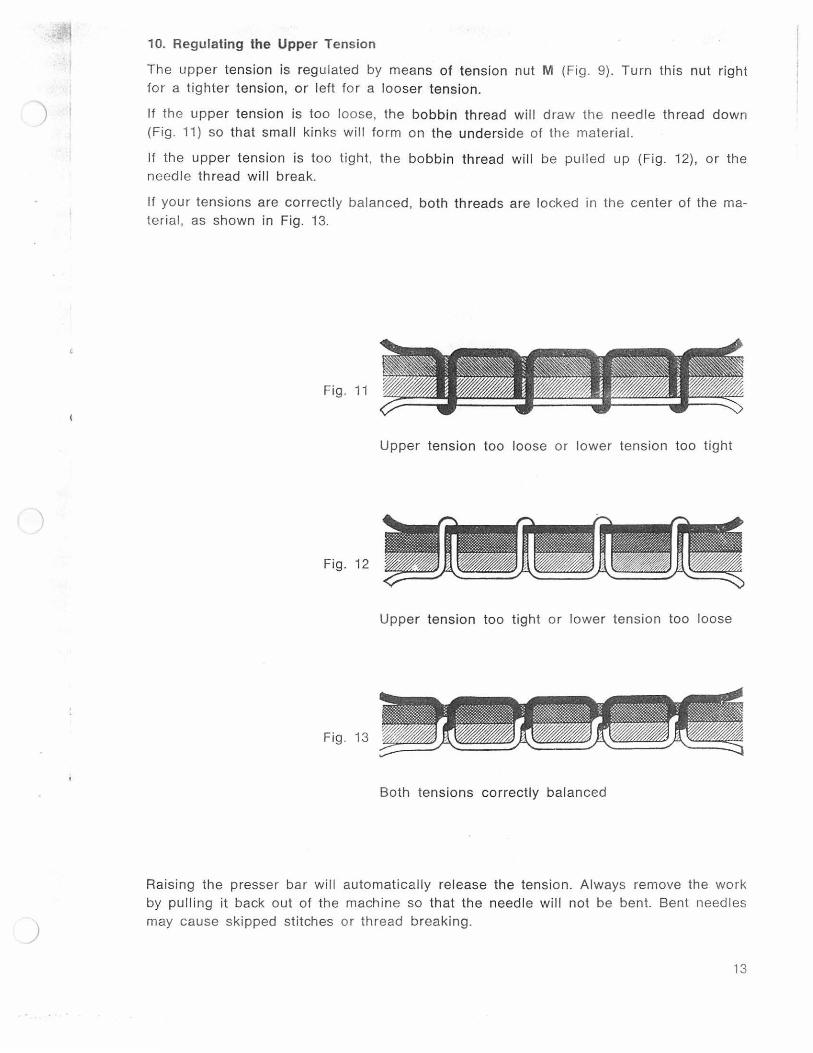
10. Regulating the Upper Tension
The upper tension is regulated by means of tension nut M (Fig. 9). Turn th is nu t right for a tighter tension, or left for a looser tension.
If the upper tension is too loose, the bobbin thread will draw the needle thread down (Fig. 11) so that small kinks will fo rm on the underside of the material.
If the upper tension is too tight, the bobbin thread w ill be pulled up (Fig. 12), or the needle thread will break.
If your tens ions are correctly balanced , both threads are locked in the center of the ma-terial , as shown in Fig. 13.
Fig. 11
Upper tension too loose or lower tension too tight
Fig. 12
Upper tension too tight or lower tension too loose
Fig. 13
Both tensions correctly balanced
Raising the presser bar w ill automatically release the tension. Always remove the work by pulling it back out of the machi ne so that the needle will not be bent. Bent needles may cause skipped stitches or thread break ing.
13

. .. .. . . .
11. Regulating the Lower Tension
The lower tension is regulated by means of tension screw Z (Fig. 7) on the bobbin case. Take the bobbin case out of the machine and .use the hook screwdriver to regulate the tension. Turn screw Z to the right for a tighter tension, or to the left for a weaker ten-sion.
The tension is correct if a noticeable resistance of spring y (Fig. 7) has to be overcome when pulling the thread out of the bobbin case.
12. Regulating the Stitch Length
The stitch length is regulated by turning thumb nut S (Fig. 14) on the feed regulator fever. Turn the thumb nut right for shorter stitches, or left, for longer stitches.
The numbers on the left of the scale indicate the stitch length in millimeters.
In order to prevent damage to .the material, the machine should not be switched to re-verse stitching during the binding operation. Operate the reverse feed control only to backtack the end of the seam with 2 or 3 stitches. J
R 7768
Fig. 14
. · .. ·. · .· . . : .·: · .. ........... ..... . . .
I.

)
l . J.
1 · ~ •
13. Regulating the Pressure on the Material
The amount of pressure exerted on the material by the presser foot is regulated by screw V (Fig. 4). Turn . the screw in for more pressure, or out for less pressure.
The amount of pressure to be exerted by the presser foot must be adapted to the ma-terial to be sewn. The pressure is set correctly if the material is advanced through the machine evenly without being injured by the teeth of the feed dog.
14. The Horizontal Rotary Hook
The time-tested System 134 hook features a welcome improvement over the old-type sewing hook in that its gib is secured by only one screw (e in Fig. 15) instead of the three screws used previoysly.
The gib can be easily removed for a thorough cleaning of the hook or in case of thread jamming in the hook raceway. Since the hook gib is secured by one screw, and the hook thread guard by three, the two parts cannot possibly be confused .
Since the new hook gib is resilient , the sewing hook will hardly be jammed completely if thread should enter the hook raceway.
R 5271
Fig. 15
15
....

)
15. Dismantling the Sewing Hook
Practised operators who have formed the habit of holding the thread ends and of bring-ing the take-up lever to its highest point when beginning or ending a seam will hardly encounter thread jamming in the hook raceway. Yet, admittedly, there is always an ex-ception to the rule.
If thread should happen to jam in the hook raceway, try to pull it out as you turn the balance wheel back and forth slightly. If this action does not free the jammed thread, dismantle the sewing hook, as instructed below:
1. Tift the machine back.
2. If the balance wheel can still be turned without applying force, raise needle bar and take-up lever. If not, turn out screws a and b (Fig. 16) and remove bobbin case position finger.
3. Remove bobbin case cap and bobbin.
4. Loosen set screw e (Fig. 15) and remove hook gib.
5. Turn balance wheel until point 1 of the hook raceway is between hook point g and point f of the thread pull-off flange (Fig. 16). Only in this position can the bobbin case base be removed.
R 7764
Fig. 16
..........

)
6. Pull out bobbin case base
7. Clean the hook raceway tl1oroughly and remove remnunb o1 thread with a pointed wooden instrument, but nP.ver with a screwd river or scissors
8 Replace bobbin case position finger and bobbin case base making sure that the bo bbin case position finger enters groove i in the base.
9 Slide the rear end of hook gib d into the small groove. as shown in Fig. 17, and in-sert and tighten sc rew e.
R 7763
,.,
)
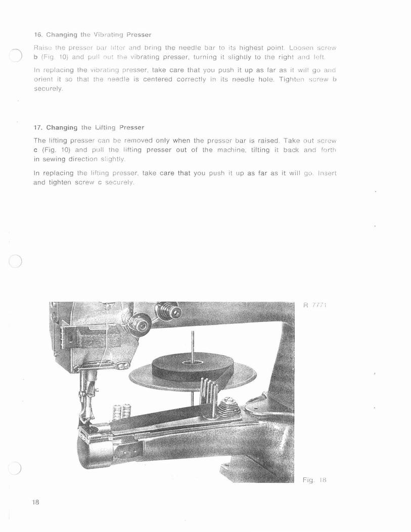
16. Changing the Vibratmg Presser
Rc11su the presst:r bdr l1it..:r and bnng the needle b'lr to its highest point Loosen <;Crt·w b (F1q 10) and pull r,ut tne vib rat1ng presser. turning it sl ightly to the right c111d l·'ft
In replacmg the viOrcltlng presser. take care that you push it up as far as 1t 'NIII gu ttrlc!
orient it so that rhe 'leedle is centered correctly in its needle hole. Tightt!n <>crew b
securely
17. Changing the Lifting Presser
The lifting presser can be removed on ly when th e presser bar is raised . Take out screw c (Fig. 10) and pull the l1fting presser out of the machine. ti lting it back ancl f()rth in sewing direct1on sl1ghtly
In replacing the llftmg presser. take care that you push it up as fa r as it will qo lnsen and tighten screw c securely
R I,- i i
Fig IB
18

)
18. Ordering Attachments
When o rdering attachments. surf n· tape gu ides and bmdc·r s pl<~<lse submit suff ic ient sample swatches and tape lor testing pur poses, and st<1l0. 11H' m:wrmum thickness of fabric to clea r the bi nder (<111uwrnp irH c. ross seams. etc_)
A number is stamped on ev(•ry bllldr•r t'. g
40425 X 10.0 X 3.5
whrch ind icates the part number of the brnder (40425). the wi<i1t· of l)rnding accommodat-ed (10.0 = 10.0 mrn). and the c lt•ar:mcc of the binder lips f: '\ 111 rnrlli meters_
If the band width varies con~rckr ,~!Jiy. rl may be neccssar v i<' c:--dw11ge the feed dog 1he need le plate and the pr0ssu J<;oi a!-3 well.
19. Different Subclass M achines
Fig. 19 shows the b inding of ::l ~.!H, , upper wttl1 the Pfaff 3:~~--·1 ·, 'Ill~· machine is fitterl witl1 a feed-synchronized binder VJilH l. t•ulls the btnding lro11~ th t;:~pe reel after each s1rtcll.
R 7978
Fig_ 19
19

)
R 5659
Fig. 20
The Pfaff 335-39 is fitted w ith a binder which folds down both edges of the bias binding simultaneously.
The mach ine shown in Fig. 20 is a Pfaff 335-39-154 which is used for applying pl ush o r chinchilla binding w ith torn or cut edges.
With this type binding, the edges are folded dow n also. The binder and the tape guide o.re mounted on the feed-synchronized attachment bracket.
20
)
R7909
Fig. 21
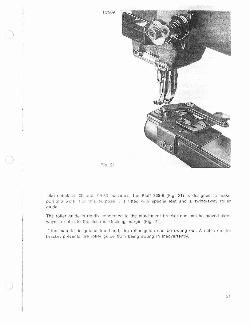
Like subclass -09 and -09-33 machines, the Platt 335-9 (Fig. 21) is designed to make portfolio work . For this purpose it is fitted with special feet and a swing-away roller guide.
The roller guide is rigidl y connected to the attachment bracket and can be moved side-ways to set it to the desired stitching margin (Fig. 21 ).
If the material is guided free-hand, the roller guide can be swung out. A notch on the bracket prevents the ro ller guide from being swung in inadvertently.
21

)
R 7344
Fig. 22
Special Features of the Pfaff 335-332 X 251
An improved version of the Pfaff 335- 132. this machine is specially designed for setting sleeves in overcoats, sackcoats. ladies' su its and similar garments.
On the Pfaff 335-132, the operator had to work in the extra fullness by hand, while on the Pfaff 335-332 X 251 his task is performed by the upper feed accelerator mechanism.
When the knee lever is in its normal position, both the upper and under feed mecha-nisms operate at the same rate of speed, as set on the feed regulator. The upper feed is accelerated by pressing the knee lever to the right or by operating the left treadle (on spec iall y fitted machines).
An optical acce leration indicator permits to read off the rate o f upper feed acceleration at a glance. If all five dots light up (Fig. 22), the upper feed works at its highest speed wh ich then is about 25 per cent faster than that of the under feed.
) When the stitch length is reduced. the speed ratio between upper and under feed is reduced accordingly.
22
)
R 7268
Fig. 23
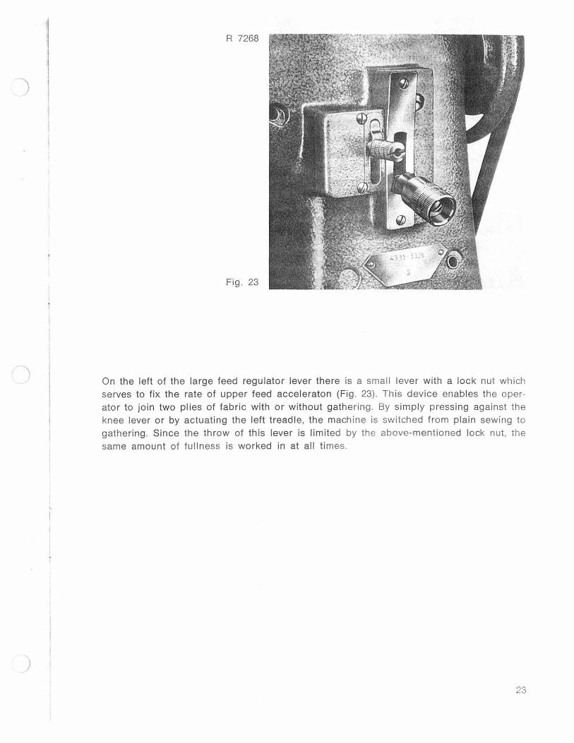
On the left of the large feed regulator lever there is a small lever with a lock nut which serves to fi x the rate of upper feed acceleraton (Fig. 23). Th is device enables the oper-ator to join two plies of fabric w ith or without gathering. By simply pressing against the knee lever or by actuat ing the left treadle, the machine is switched from plain sewing to gathering. Since the throw of this lever is limited by the above-mentioned lock nut, the same amou nt of fullness is worked in at all times.
23
I l I 1 4
I t l
)
)
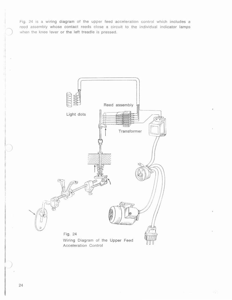
Fig. 24 is a wi ring diagram of the upper feed acceleration control which inc ludes a reed assembly whose contact reeds close a circuit to the individual ind icator lamps when the knee lever or the left treadle is pressed.
24
Reed assembly
Light dots
Transformer
Fig. 24
Wiring Diagram of the Upper Feed Acce leration Control

)
R 7326
Fig. 25
To facil itate the insertion and the removal of the work piece, the machine is fitted with a small treadle (Fig. 25) which serves to raise the presser foot and may be arranged on the right or left, as desired.
The swing-away edge guide is laterally adjustable and is mounted on a hand rest which is rig idly connected to the cylinder arm.
A detachable work support abets the handling of bulky garments.
25

20. Trouble Shooting
) Machine Skips Stitches
1. Needle Incorrectly inserted
2. Wrong needle
3. Needle bent or too fine fo r the thread used
Thread Breaks
1. Any of the above-mentioned conditions may cause thread breakage
2. Tension too ti ght
3. Poor or knotty thread used
4. Thread snarled up on spool pin
Faulty Stitch Formation
1. Tension either too tight or too loose
) 2. Needle and thread sizes do not match. Bobbin th read may be thinner, but not thicker, than needle thread
3. Li nt accumulated between tension d iscs or under bobbin case tension spring
Machine Works Heavily
1. Pieces of thread jammed in hook raceway
2. Mechan1sm c logged or lack of o il
)
26

l ) j
I
)
Contents
Foreword
1. General .
2. Engaging and Disengaging the Swing Mechanism
3. Cleaning and Lubricating the Machine
4. Winding the Bobbin
5. Removing the Bobbin and Threading the Bobbin Case
6. Selecting the Correct Needle
7. Changing the Needle .
8. Threading the Needle .
9. Drawing Up the Bobbin Thread
10. Regulating the Upper Tension .
11. Regulating the Lower Tension .
12. Regulating the Stitch Length
13. Regulating the Pressure on the Material .
14. The Horizontal Rotary Hook
15. Dismantling the Sewing Hook
16. Changing the Vibrating Presser
17. Changing the Lifting Presser
18. Ordering Attachments .
19. Different Subclass Machines
Pfaff 335-17
Pfaff 335-39
Pfaff 335-9
Pfaff 335-332 X 251
20. Trouble Shooting .
Page
3
4
4
4
7
9
10
11
11
12
13
14
14
15
15
16
18
18
19
19
19
20
21
22
26
27

)
)
No. 7902 engl. P 268
~ I o o 0 .~ o • ~
... ' .. .. .. .. .
C-P-FA_F_F )®
Printed in Germany