pg 1 install guide ct100 - lorenz hd | the home … · pg 1 install guide ct100 caution • turn...
TRANSCRIPT

PG 1
Install Guide CT100Caution
• Turn off electricity to the HVAC system before installing or servicing thermostat or any part of the system.�•�Do�not�turn�electricity�back�on�until�work�is�completed.•�Do�not�short�(jumper)�across�electric�terminals�at�the�control�on�the�furnace�or�air�conditioner�to�test�the�system.�This�may�damage�the�thermostat.•�All�wiring�must�conform�to�local�codes�and�ordinances.•�This�thermostat�is�designed�for�use�with�4AA�alkaline�batteries�and/or�24�VAC�C-wire�(or�a�12-24�AC�or�DC�source)�and�millivolt�gas�systems.�Each�thermostat�relay�load�should�be�limited�to�1.0�amp;�higher�amperage�may�cause�damage�to�the�thermostat.
Caution �To�avoid�electrical�shock�and�to�prevent�damage�to�the�furnace,�air�conditioner,�and�thermostat,�disconnect the power supply�before�beginning�work.�This�can�be�done�at�the�circuit�breaker.
ENGLISH1202-001-002
Power�Gridstatusindicator
top�cover
Touch�screen
Wireterminals
Modebutton
buttonMENU
Resetbutton
HVACselectionsswitches
bottom�cover

PG 2PG 2
WHAT TYPE WAS YOUR OLD SYSTEM?
First�verify�that�the�existing�system�operates�for�HEAT�and�COOl�[if�outside�temperature�is�below�60oF don’t�check�COOL]�.�Then�you�need�to�determine�what�type�of�HVAC�system�the�thermostat�will�be�controlling.��Heat�PUmp�or�Convention�System?
1)�Look�on�the�outside�compressor�unit�and/or�the�inside�air�handler�unit�for�the�words�“Heat�Pump”�which�uses�the�outside�compressor�for�heating�as�well�as�cooling�=�You�have�a�Heat�Pump.2)�A�heat�pump�needs�a�“changeover”�wire�to�change�from�heat�to�cool;�so�it�must�have�a�wire�connected�to�the�O�terminal�or�the�B�terminal�on�the�old�thermostat�=�You�have�a�Heat�Pump.Note�-�The�old�thermostat�may�have�an�emergency�wire�(E),�an�emergency�ON/OFF�switch,�and�an�EMER�on�light.�If�so,�be�sure�the�EMER�switch�is�turned�off�for�the�next�test.4)�Using�the�old�thermostat�in�HEAT�mode,�Increase�the�target�just�enough�to�turn�on�the�heat;�if�it�is�a�heat�pump,�the�outside�compressor�unit�will�be�running�in�heat.�=�You�have�a�Heat�Pump.5)�If�you�have�a�heat�pump,�you�may�also�have�another�source�of�heat�(auxiliary)�which�can�be�electric,�gas�or�oil.�You�must�determine�what�that�back�up�heat�is�so�you�can�set�the�thermostat�for�the�proper�system.
In�a�conventional�heating/cooling�system�there�is�a�single�source�of�heat�(electric,�gas�or�oil)�plus�an�outside�compressor�for�just�cooling.�There�will�not�be�an�O�or�B�or�E�wire.Often�the�home�owner�will�know�what�type�of�conventional�system�they�have.��Whichever�has�the�largest�energy�bill�is�the�heater.

PG 2
PG 3
TOOLS
You�will�need�a�small�Phillips�screwdriver�and�a�drill�with�3/16-in.�(4.8mm)�bit�for�wall�mounts.�
LOCATION��Replacement�installations�-�mount�the�CT100�in�place�of�the�
old�thermostat.��A�new�location�will�require�moving�your�wiring.For�new�installations�and�relocating�the�CT100�-��follow�the�guidelines�listed�below:�•�Locate�the�thermostat�on�an�inside�wall,�about�5�ft.�(1.5m)�above�the�floor,�and�in�a�room�that����is�used�often.•�Do�not�install�it�where�there�are�unusual�heating�conditions,�such�as:�in�direct�sunlight;�near�����a�lamp,�radio,�television,�radiator�register,�fireplace;�near�hot�water�pipes�in�a�wall;�or�near�a���stove�on�the�other�side�of�a�wall.•�Do�not�locate�in�unusual�cooling�conditions,�such�as:�on�a�wall���separating�an�unheated�room;�or�in�a�draft�from�a�stairwell,�door,���or�window.•�Do�not�locate�in�a�damp�area.�This�can�lead�to�corrosion�that�will�shorten�thermostat�life.� •�Do�not�locate�where�air�circulation�is�poor,�such�as:�in�a�corner,�an�alcove;�behind�an�open�door.�•�Do�not�install�the�CT100�until�all�construction�and�painting�has���been�completed.•�This�thermostat�does�not�require�leveling.
Good
5ft.(1.5m)

PG 4
REMOVE OLD UNIT
Switch OFF electricity to the HEATING and COOLING systems.� Then�follow�these�steps:•�Remove�cover�from�old�thermostat.�Most�are�snap-on�types�and�simply�pull�off.��Some�have�locking�screws�on�the�side�or�front.��These�must�be�loosened.��DO�NOT�remove�wires.��Note�the�letters�printed�near�the�terminals.��Attach�labels�(enclosed)�to�each�wire�for�identification.
Caution Read instructions carefully before removing any wiring from existing thermostat. Wires must be labeled before they are removed. THERE IS NO STANDARD COLOR CODE. When remov-ing wires from their terminals, ignore the color of the wires and LABEL THEM by the lettered terminal where they were screwed.
•�Label�the�wires�one�at�a�time.��You�must�label�all�the�wires�before�you�proceed.��•�With�all�wires�labeled,�remove�them�from�the�old�unit.•�Make�sure�the�wires�do�not�fall�back�inside�the�wall.��You�can�wind�them�around�a�pencil�to�keep�them�from�falling.•�Loosen�all�screws�on�the�old�thermostat�and�remove�it�from�the�wall.
R W
G

PG 4
PG 5
What wires do you have?�Make�sure�your�wires�are�labeled.�This�may�require�you�to�find�
the�‘other�end’�connection�for�each�wire�on�your�heating�or�air�conditioning�equipment�and�read�the�label�there.�Refer�to�the�Wire�Reference�page�at�end�of�install�section�for�better�understanding�of�wire�labels�from�different�HVAC�system�makers.
IMPORTANT: �The�CT100�runs�on�4�AA�alkaline�batteries�and/or�the�C�wire�if�available.�If�you�do�not�have�a�C�wire�you�can�run�a�new�wire�from�the�HVAC�or�use�a�standard�12-24V�[AC�or�DC]�wall�transformer.
IMPORTANT: If�you�have�both�RH�and�RC�you�need�to�remove�the�jumper�wire�between�these�2�terminals.
Prepare Wires
Please�follow�these�guidelines�for�safe�and�secure�wire�connections:•�You�will�need�at�least�2.6”�of�wire�for�each�of�your�connections�to�the�CT100.��•�If�you�do�not�have�enough�wire,�splice�additional�wire�to�allow�enough�slack.� •�Terminals�accept�wires�from�16-22awg.•�Fan�out�wires�below�the�hole�as�shown.•�Remove�insulation�1/8”�from�the�tip�of�each�wire.•�When�handling,�take�care�not�to�damage�the�labels�for�each�wire.
GC Y RW
2.6"
from�HVAC System
Wire�Terminals
Jumper�wire
Y RH RC G A

PG 6
Find�the�step-by-step�diagram�for�your�system � � ��������•�Select�the�reference�page�
with�your�wiring�diagram�and�set-up�information�below.
•�The�C-wire�is�optional�but�preferred�for�all�installations.�It�will�make�batteries�last�a�long�time.��(This�connection�is�shown�as�dotted�in�diagrams).��
•�Hot�Water�systems�accessories�are�on�Page�17.
•�If�your�combination�of�wires�is�not�shown,�you�can�use�the�wiring�table�at�the�end�of�the�install�section�to�find�your�connections.�If�additional�help�is�required,�please�contact�Technical�Support�at��888-721-0147.
G
�W�Y�RH�RC�G
5�WireHeat/Cool
From
HVAC
RCCY RHW
W�Y�R�G�4�Wire Heat/Cool
From
HVAC
GCY RW
�W�R�G 3�Wire Heat
From
HVAC
C R GW
From
HVAC
C W
W R
R
2�Wire Heat
WIRES
WIRES
WIRES
WIRES
GR
�Wn�Yn�R G Multi-stage�CoolMulti-Stage�Heat
From
HVAC
YnC Wn
B�or�O��AUXn�Yn R�G Multi-stage ��Heat�Pump�������w/�
Multi-stage�������Aux�Heat
From
HVAC
RC O
or
WnB GYnG
�B�or�O��Y�R�G 4�Wire�Heat�Pumpw/o�Aux�Heat
From
HVAC
RC O
or
YB
WIRES
WIRES
WIRES
Go�To�Page�16 Go�To�Page�17Go�To�Page�16
Go�To�Page�14 Go�To�Page�15 Go�To�Page�15Go�To�Page�14

PG 6
PG 7
•�“Fan�out”�wires�as�illustrated�with�CT100�below�the�wall�opening.��As�in�the�example:�fan�out�the�wires�so�that�the�C�wire�is�above�the�C�terminal,�the�W�above�the�W.�This�allows�the�CT100�to�fit�snug�to�the�wall.
Caution Do not allow wires to touch each other or parts on thermostat.
•�Position�the�wires�behind�the�CT100�and�up�over�the�terminal�area.•�Do�not�bunch�wires�behind�the�CT100.��Feed�any�slack�back�into�the�wall�opening.
Connect Your Wires
•�Connect�labeled�wires�only�to�a�terminal�with�the�same�letter�label.•�Insert�the�wire�in�the�terminal�well�and�tighten�the�screw�securely.NOTE:�If�you�wish�you�can�mount�the�CT100�to�the�wall�first,�and�then�connect�the�wires.•�The�CT100�can�be�externally�powered�with�a�power�source�rated�from�12V�to�24V,�AC�or�DC,�at�100ma�or�greater.�If�used,�connect�to�the�C�and�RH�terminals�(no�polarity).
from�HEAT/COOL�system
C B O W W2 Y Y2 RHRCG A
RHY G
C W

PG 8
Mount the CT100 to Wall
1.�Hold�the�CT100�against�the�wall,�with�the�wires�coming�over�the�top;�above�terminal�block.�The�CT100�will�cover�the�hole�in�the�wall.�2.�Position�CT100�for�best�appearance.�3.�Attach�the�CT100�to�the�wall�with�the�screws�provided.4.�If�you�are�mounting�the�CT100�to�sheet�rock�or�if�you�are�using�the�old�mounting�holes,�use�the�plastic�anchors�provided.�5.�Mark�first�and�drill�a�3/16-in.(4.8mm)�hole�for�the�insert�at�each�screw�
location,�then�mount�the�unit.
Wall
Wires
Wallanchor
CT100
from�HEAT/COOL�system
CWY
RH G
Place�wires�like�this
Screw�to�wall
PG 8
PG 9
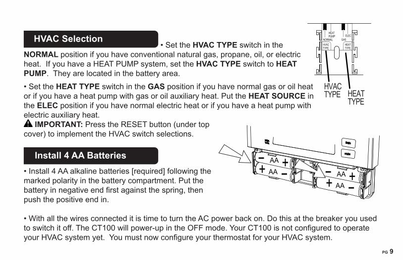
HVAC Selection
�•�Set�the�HVAC TYPE�switch�in�the�NORMAL position�if�you�have�conventional�natural�gas,�propane,�oil,�or�electric�heat.��If�you�have�a�HEAT�PUMP�system,�set�the�HVAC TYPE�switch�to�HEAT PUMP.��They�are�located�in�the�battery�area.��•�Set�the�HEAT TYPE�switch�in�the�GAS position�if�you�have�normal�gas�or�oil�heat�or�if�you�have�a�heat�pump�with�gas�or�oil�auxiliary�heat.�Put�the�HEAT SOURCE�in�the ELEC�position�if�you�have�normal�electric�heat�or�if�you�have�a�heat�pump�with�electric�auxiliary�heat.�
IMPORTANT:�Press�the�RESET�button�(under�top�cover)�to�implement�the�HVAC�switch�selections.
Install 4 AA Batteries
•�Install�4�AA�alkaline�batteries�[required]�following�the�marked�polarity�in�the�battery�compartment.�Put�the�battery�in�negative�end�first�against�the�spring,�then�push�the�positive�end�in.� •�With�all�the�wires�connected�it�is�time�to�turn�the�AC�power�back�on.�Do�this�at�the�breaker�you�used�to�switch�it�off.�The�CT100�will�power-up�in�the�OFF�mode.�Your�CT100�is�not�configured�to�operate�your�HVAC�system�yet.��You�must�now�configure�your�thermostat�for�your�HVAC�system.
AAAA AA
AA
HEATPUMP
HVACTYPE
HVACTYPE
HEAT�TYPE
HEATTYPE
NORMAL GASELEC
PG 10
Caution Special Battery WarningAlways�replace�the�batteries�as�soon�as�the�“Low�Batt”�flashes.�The�thermostat�is�a�battery�powered�device.�You�must�be�responsible�to�replace�batteries�before�they�run�out.�Failure�to�replace�batteries�can�result�in�overheating�or�excessive�cooling�of�your�house.
•�Even�if�the�“Low�Batt”�indicator�does�not�flash,�you�should�always�replace�the�batteries�at�least�once�a�year.�Replacing�the�batteries�also�helps�to�prevent�leakage�that�can�corrode�and�damage�the�thermostat.
•�If�you�are�leaving�your�home�for�a�month�or�more,�you�should�replace�the�batteries�as�a�precaution�against�battery�failure�in�your�absence.
•�Always�use�new�alkaline�batteries.
•�Failing�to�replace�the�batteries,�when�necessary,�could�cause�the�thermostat�to�lose�power�or�malfunction.�If�the�thermostat�loses�power,�then�the�thermostat�will�not�control�the�temperature�which�could�result�in�your�HVAC�system�not�functioning�as�you�intended�and�lead�to�possible�damage�from�overheating�or�excessive�cooling.
•�If�the�thermostat�batteries�fail�with�the�heat�OFF,�this�can�result�in�NO�HEAT�and�possible�frozen�or�broken�pipes�and�water�damage.
•�If�the�thermostat�batteries�fail�with�the�cool�OFF,�this�can�result�in�NO�COOL�and�could�cause�possible�damage�or�excessive�temperatures.
PG 10
PG 11
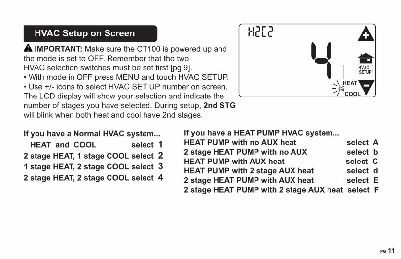
HVAC Setup on Screen
IMPORTANT:�Make�sure�the�CT100�is�powered�up�and�the�mode�is�set�to�OFF.�Remember�that�the�two�HVAC�selection�switches�must�be�set�first�[pg�9].•�With�mode�in�OFF�press�MENU�and�touch�HVAC�SETUP.•�Use�+/-�icons�to�select�HVAC�SET�UP�number�on�screen.The�LCD�display�will�show�your�selection�and�indicate�the�number�of�stages�you�have�selected.�During�setup,�2nd STG will�blink�when�both�heat�and�cool�have�2nd�stages.
If you have a Normal HVAC system... HEAT and COOL select 12 stage HEAT, 1 stage COOL select 2 1 stage HEAT, 2 stage COOL select 3 2 stage HEAT, 2 stage COOL select 4
If you have a HEAT PUMP HVAC system...HEAT PUMP with no AUX heat select A2 stage HEAT PUMP with no AUX select b HEAT PUMP with AUX heat select C HEAT PUMP with 2 stage AUX heat select d 2 stage HEAT PUMP with AUX heat select E 2 stage HEAT PUMP with 2 stage AUX heat select F
HEAT2NDSTG
HVACSETUP
COOL
PG 12
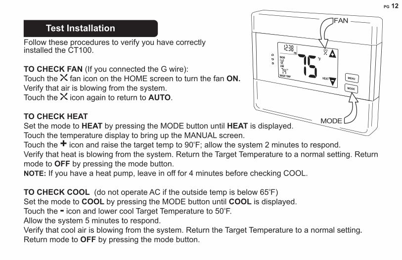
Test Installation
Follow�these�procedures�to�verify�you�have�correctly installed�the�CT100.
TO CHECK FAN�(If�you�connected�the�G�wire):��Touch�the� �fan�icon�on�the�HOME�screen�to�turn�the�fan�ON. Verify�that�air�is�blowing�from�the�system.� Touch�the� �icon�again�to�return�to�AUTO.
TO CHECK HEAT Set�the�mode�to�HEAT by�pressing�the�MODE�button�until�HEAT is�displayed.�Touch�the�temperature�display�to�bring�up�the�MANUAL�screen.�Touch�the�+�icon�and�raise�the�target�temp�to�90oF;�allow�the�system�2�minutes�to�respond.�Verify�that�heat�is�blowing�from�the�system.�Return�the�Target�Temperature�to�a�normal�setting.�Return�mode�to�OFF by�pressing�the�mode�button.�NOTE:�If�you�have�a�heat�pump,�leave�in�off�for�4�minutes�before�checking�COOL.�
TO CHECK COOL��(do�not�operate�AC�if�the�outside�temp�is�below�65oF)�Set�the�mode�to�COOL by�pressing�the�MODE�button�until�COOL is�displayed.Touch�the�-�icon�and�lower�cool�Target�Temperature�to�50oF.�Allow�the�system�5�minutes�to�respond.�Verify�that�cool�air�is�blowing�from�the�system.�Return�the�Target�Temperature�to�a�normal�setting. Return�mode�to�OFF by�pressing�the�mode�button.�
FAN
MODE
MENU
MODE
FLINK
RADIO
TARGET TEMP
1
HEAT
AUTO

PG 12
PG 13
Congratulations, you have successfully installed your unit. Please proceed to the OPERATING Guide to initialize the CT100.
IMPORTANT:�If�you�have�labeled�and�connected�your�wires�and�followed�the�correct�HVAC�setup,��and�your�system�still�does�not�operate,�contact�technical�support�at�888-721-0147.�
STATEMENT�OF�USE:�This�thermostat�can�be�used�with�4AA�batteries,�24VAC�(C�wire),�24VAC�adapter,�heating�and�cooling�systems�and�also�millivolt�heating.��It�cannot�be�used�with�120v-240v�systems.�This�thermostat�is�digital�and�your�desired�heat�or�cool�temperatures�can�easily�be�set�on�the�large�touch�screen�with�the�+/-�buttons.��A�minimum�4�minute�off�time�protects�the�compressor�from�damage.�This�icon� �indicates�compressor�protection�is�active.��
This�thermostat�runs�on�4AA�batteries.�The�CT100�can�be�externally�powered�with�a�power�source�rated�from�12V�to�24V,�AC�or�DC,�at�100ma�or�greater.�If�used,�connect�to�the�C�and�RH�terminals�(no�polarity).�The�24VAC�“C”�wire�is�the�other�side�of�the�24VAC�heating�transformer�and�can�be�found�where�the�other�thermostat�wires�connect�at�the�wall�or�at�the�furnace.���Do�not�use�the�common�or�ground�side�of�the�line�voltage.��
MENU
MODE
FLINK
RADIO
TARGET TEMP
1
HEAT
AUTO

PG 14
Step-by-step�wiring�diagrams
WIRES 2 Wire Heat GAS MILLIVOLT or 24VAC system
STEP�1�-�Connect�the�R�wire�to�the�RH�terminal.�� This�connects�the�heat�power.STEP�2�-�Connect�the�W�wire�to�the�W�terminal.� This�connects�the�heat.����������������STEP�3�-��Optional�-�Connect�the�C�wire�to�the�C�terminal.Your�heater�is�now�connected�to�the�CT100.��
Please�Go�To�Page�6��
WIRES 3 Wire Heat
STEP�1�-�Connect�the�R�wire�to�the�RH�terminal.�This�connects�the�heat�power.STEP�2�-�Connect�the�W�wire�to�the�W�terminal.�This�connects�the�heat.STEP�3�-�Connect�the�G�wire�to�the�G�terminal�on�the�thermostat.�This�connects�the�fan.STEP�4�-��Optional�-�Connect�the�C�wire�to�the�C�terminal. Your�system�is�now�connected�to�the�CT100.
Please�Go�To�Page�6
C�B�O�W�W2�Y�Y2 RH�RC�G�A�
POWER
HVAC�SYSTEM
THERMOSTAT
W RC
THERMOSTAT�TERMINALS
HVAC�SYSTEM
THERMOSTAT
C�B�O�W�W2�Y�Y2 RH�RC�G�A
POWERW R GC
THERMOSTAT�TERMINALS
PG 14
PG 15
W Y R G
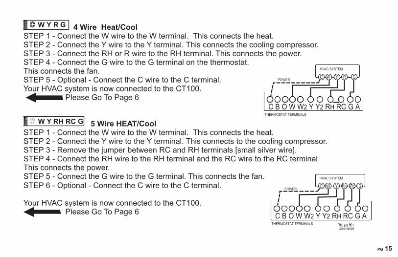
WIRES 4 Wire Heat/Cool STEP�1�-�Connect�the�W�wire�to�the�W�terminal.��This�connects�the�heat.STEP�2�-�Connect�the�Y�wire�to�the�Y�terminal.�This�connects�the�cooling�compressor.STEP�3�-�Connect�the�RH�or�R�wire�to�the�RH�terminal.�This�connects�the�power.STEP�4�-�Connect�the�G�wire�to�the�G�terminal�on�the�thermostat.�This�connects�the�fan.STEP�5�-�Optional�-�Connect�the�C�wire�to�the�C�terminal. Your�HVAC�system�is�now�connected�to�the�CT100. �Please�Go�To�Page�6����
W Y RH RC G
WIRES 5 Wire HEAT/Cool
STEP�1�-�Connect�the�W�wire�to�the�W�terminal.��This�connects�the�heat.STEP�2�-�Connect�the�Y�wire�to�the�Y�terminal.�This�connects�to�the�cooling�compressor.STEP�3�-�Remove�the�jumper�between�RC�and�RH�terminals�[small�silver�wire].STEP�4�-�Connect�the�RH�wire�to�the�RH�terminal�and�the�RC�wire�to�the�RC�terminal.� This�connects�the�power.STEP�5�-�Connect�the�G�wire�to�the�G�terminal.�This�connects�the�fan.STEP�6�-�Optional�-�Connect�the�C�wire�to�the�C�terminal.
Your�HVAC�system�is�now�connected�to�the�CT100. Please�Go�To�Page�6��
HVAC�SYSTEM
THERMOSTAT�TERMINALS
C�B�O�W�W2�Y�Y2 RH�RC�G�A
POWER W Y R GC
HVAC�SYSTEM
THERMOSTAT�TERMINALS
C�B�O�W�W2�Y�Y2 RH�RC�G�A�
POWER W Y RH GC RC
*RC�and�RHdisconnected

PG 16Wn Yn R G Multi-stage Heat and Multi-stage Cool
The�CT100�can�handle�up�to�2�stages�of�HEAT�and�2�stages�of�COOL. STEP�1�-�Connect�the�W�and�W2�wires�to�the�W�terminals�respectively.� This�connects�the�stages�of�HEAT.STEP�2�-�Connect�the�Y�and�Y2�wires�to�the�Y�and�Y2�terminals�respectively.� This�connects�the�stages�of�COOL.STEP�3�-�Connect�the�RH�or�R�wire�to�the�RH�terminal.� This�connects�the�power.STEP�4�-�Connect�the�G�wire�to�the�G�terminal.� This�connects�the�fan.STEP�5�-��Optional�-�Connect�the�C�wire�to�the�C�terminal.Your�HVAC�system�is�now�connected�to�the�CT100.�
�Please�Go�To�Page�6������
Heat Pump (heat/cool) without Auxiliary Heat STEP�1�-�Connect�O�wire�to�the�O�terminal�or�B�wire�to�the�B�terminal.� This�connects�the�change-over�valve.�IMPORTANT NOTE: If�you�have both�O�and�B�-�connect�only�the�O�wire�to�the�O�terminal�and��DO�NOT�connect�B�to�the�B�terminal��(see�wire�reference�under�Trane�for�B�wire�terminal).STEP�2�-�Connect�the�Y�wire�to�Y�terminal.�This�connects�the�compressor.STEP�3�-�Connect�the�R�wire�to�the�RH�terminal.��This�connects�the�power.STEP�4�-�Connect�the�G�wire�to�the�G�terminal.�This�connects�the�fan.STEP�5�-��Optional�-�Connect�the�C�wire�to�the�C�terminal.Your�HVAC�system�is�now�connected�to�the�CT100.
Please�Go�To�Page�6����
HVAC�SYSTEM
THERMOSTAT�TERMINALS
C�B�O�W�W2�Y�Y2 RH �RC�G�A�
POWER W Y Y2 GRC W2
HVAC�SYSTEM
THERMOSTAT�TERMINALS
C�B�O�W�W2�Y�Y2 RH�RC�G�A
POWER B O Y GRC
oror
PG 16
PG 17
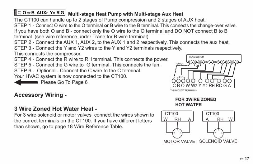
O or�B AUXn Yn R G Multi-stage Heat Pump with Multi-stage Aux Heat The�CT100�can�handle�up�to�2�stages�of�Pump�compression�and�2�stages�of�AUX�heat.STEP�1�-�Connect�O�wire�to�the�O�terminal�or�B�wire�to�the�B�terminal.�This�connects�the�change-over�valve.�If�you�have�both�O�and�B�-�connect�only�the�O�wire�to�the�O�terminal�and��DO�NOT�connect�B�to�B�terminal��(see�wire�reference�under�Trane�for�B�wire�terminal).STEP�2�-�Connect�the�AUX�1,�AUX�2,�to�the�AUX�1�and�2�respectively.�This�connects�the�aux�heat.STEP�3�-�Connect�the�Y�and�Y2�wires�to�the�Y�and�Y2�terminals�respectively.� This�connects�the�compressor.STEP�4�-�Connect�the�R�wire�to�RH�terminal.�This�connects�the�power.STEP�5�-�Connect�the�G�wire�to��G�terminal.�This�connects�the�fan.STEP�6�-��Optional�-�Connect�the�C�wire�to�the�C�terminal.Your�HVAC�system�is�now�connected�to�the�CT100.
Please�Go�To�Page�6 Accessory Wiring - 3 Wire Zoned Hot Water Heat - For�3�wire�solenoid�or�motor�valves��connect�the�wires�shown�to�the�correct�terminals�on�the�CT100.�If�you�have�different�letters�than�shown,�go�to�page�18�Wire�Reference�Table.
SOLENOID�VALVE
W
A RH CT100�
MOTOR VALVE
W
RH������ACT100�
FOR 3WIRE ZONED HOT WATER
WR
AWR
A
HVAC�SYSTEM
THERMOSTAT�TERMINALS
C�B�O�W�W2�Y�Y2 RH�RC�G�A
POWER B GRY Y2C O
or
orAUX1 AUX2
PG 18
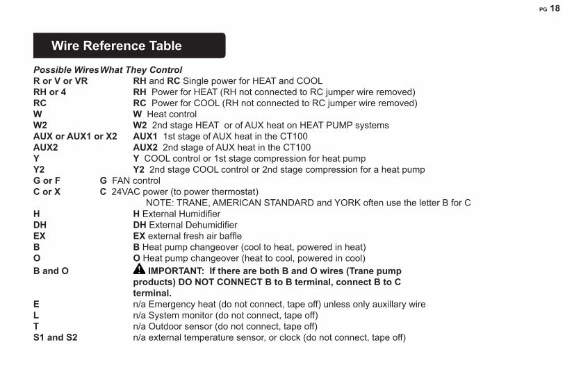
Wire Reference Table
Possible Wires What They ControlR or V or VR RH and RC Single�power�for�HEAT�and�COOLRH or 4 RH Power�for�HEAT�(RH�not�connected�to�RC�jumper�wire�removed)RC RC Power�for�COOL�(RH�not�connected�to�RC�jumper�wire�removed)W W Heat�controlW2 W2 2nd�stage�HEAT��or�of�AUX�heat�on�HEAT�PUMP�systems AUX or AUX1 or X2 AUX1��1st�stage�of�AUX�heat�in�the�CT100AUX2 AUX2��2nd�stage�of�AUX�heat�in�the�CT100 Y Y COOL�control�or�1st�stage�compression�for�heat�pumpY2 Y2 2nd�stage�COOL�control�or�2nd�stage�compression�for�a�heat�pumpG or F G FAN�controlC or X C 24VAC�power�(to�power�thermostat)�� NOTE:�TRANE,�AMERICAN�STANDARD�and�YORK�often�use�the�letter�B�for�CH H External�Humidifier�DH DH�External�DehumidifierEX EX external�fresh�air�baffleB B Heat�pump�changeover�(cool�to�heat,�powered�in�heat)O O Heat�pump�changeover�(heat�to�cool,�powered�in�cool)B and O IMPORTANT: If there are both B and O wires (Trane pump products) DO NOT CONNECT B to B terminal, connect B to C terminal. E n/a�Emergency�heat�(do�not�connect,�tape�off)�unless�only�auxillary�wireL n/a�System�monitor�(do�not�connect,�tape�off)T n/a�Outdoor�sensor�(do�not�connect,�tape�off)S1 and S2 n/a�external�temperature�sensor,�or�clock�(do�not�connect,�tape�off)��Wire Reference

PG 18
PG 19
Wire Reference cont. Possible Wires What They Control Lennox Heat Pump V or VR or R RH�Power�for�HEAT�M or Y Y COOL�controlY or W or W2 W2 2nd�stage�HEATF or G G Fan�controlR or O OX or X2 or C C
Trane Products [American Standard]B C�24VAC�power�(to�power�thermostat)�� Zoned Hot Water 2 wireYour Wires Thermostat TerminalR RHW W
3 Wire Motor Driven ValvesR or 5 RH�(power)W or 4 W��(heat�ON)Y or G or 6��(the�3rd�wire)� A���(heat�OFF)
3 Wire Solenoid ValvesR RH �(power)W A ���(heat�ON)Y or G (the�3rd�wire)���� � W ��(heat�OFF)

PG 20
Communicating Thermostat�����The�CT100�has�a�built�in�Z-Wave�radio.�This�allows�
your�thermostat�to�communicate�with�other�systems.
Network INCLUSION 1.��Set�your�primary�controller�to�INCLUDE�mode�to�add�the�thermostat�as�a�node�on�your�network�(see�your�specific�controller’s�User�Manual�for�detailed�instructions.)��2.��Press�and�release�the�MENU�button�on�the�thermostat.��3.��Press�the�MATE�button.�This�will�bring�you�to�the�network�screen�and�a�large�r1�will�be�displayed.�4.��Press�the�MATE�button�again.�This�will�initiate�the�mating�process.��When�a�device�has�joined�a�network�the�word�LINK�will�appear�under�the�radio�tower.Your�controller�will�indicate�the�thermostat�was�successfully�added�to�its�network�(see�your�specific�controller’s�User�Manual�for�details).
Network EXCLUSION 1.��Set�your�primary�controller�to�EXCLUDE�mode�to�remove�the�thermostat�as�a�node�on�your�network�(see�your�specific�controller’s�User�Manual�for�detailed�instructions.)��2.��Press�and�release�the�MENU�button�on�the�thermostat.��3.��Press�the�MATE�button�-�This�will�bring�you�to�the�network�screen�and�a�large�r1�will�be�displayed.�4.��Press�the�MATE�button,�this�will�initiate�the�mating�process.��When�a�device�has�been�removed�

PG 20
PG 21
from�a�network,�the�word�LINK below�the�radio�tower�will�disappear.Your�controller�will�indicate�the�thermostat�was�successfully�removed�from�its�network�(see�your�specific�controller’s�User�Manual�for�details).
Z-Wave and Battery Power When�your�thermostat�is�running�on�battery�power,�the�Z-Wave�radio�will�turn�off�to�help�conserve�battery�life.��The�CT100�Z-Wave�radio�module�supports�Z-Wave�beaming,�which�allows�other�devices�in�the�network�to�wake�up�the�Z-Wave�module�and�accept�commands,�and�then�go�back�to�sleep.��The�node�type�is�fixed�during�network�inclusion.��If�C-Wire�is�not�present�and�the�thermostat�is�battery�powered�during�network�inclusion,�the�thermostat�will�remain�a�frequent�listening�routing�slave�(FLiRS)�node�until�the�thermostat�is�removed�from�the�network�via�network�exclusion.
Z-Wave and C-Wire Power When�your�thermostat�is�running�on�C-Wire�power,�the�Z-Wave�radio�will�stay�on�and�actively�help�in�routing�messages�within�the�z-wave�network.��The�node�type�is�fixed�during�network�inclusion.��If�C-Wire�is�present�and�powered�during�network�inclusion,�the�thermostat�will�remain�an�always�listening�node�until�the�thermostat�is�removed�from�the�network�via�network�exclusion.

PG 22
APPENDIX 1 Multi staged HVAC theory of operation for the CT100
Staging for 2 stage normal or heat pump Cool Target Temperature Maintenance in COOL -�If�the�room�temperature�is�within�the�target�temperature�plus�the�DIFF�setting,�the�first�stage�of�cool�will�turn�on.�If�the�target�temperature�is�not�reached�within�(15�minutes),�the�second�stage�of�cooling�will�turn�on�and�join�the�first�stage�to�reach�the�target�temperature.�Target Temperature Recovery in COOL- If�the�room�temperature�is�beyond�the�new�target�temperature�plus�the�DIFF�setting,�the�first�stage�will�turn�on.�Ten�seconds�later,�the�second�stage�will�turn�on�with�the�first�stage�to�help�reach�the�new�target.With�FAST�recovery,�both�stages�stay�on�until�the�new�target�temperature�is�reached.�With�ECON�recovery,�both�stages�stay�on�until�the�DIFF�setting�is�reached.�Then,�the�second�stage�shuts�off�and�the�first�stage�stays�on�to�the�new�target.
Staging for 2 stage normal HeatTarget Temperature Maintenance in HEAT -�If�the�room�temperature�is�within�the�target�temperature�minus�the�DIFF�setting,�the�first�stage�of�heat�will�turn�on.�If�the�target�temperature�is�not�reached�within�(15�minutes),�the�second�stage�of�heat�will�turn�on�and�join�the�first�stage�to�reach�the�target�temperature.�Example:�Target�temperature�70F,�DIFF�at�2F,�maintenance�occurs�at�room�temperatures�of�69F�and�68F.Target Temperature Recovery in HEAT- If�the�room�temperature�is�beyond�the�new�target�temperature�minus�the�DIFF,�the�first�stage�will�turn�on.�Ten�seconds�later,�the�second�stage�will�turn�on�and�join�the�first�stage�to�help�reach�the�target�temperature..�With�FAST�recovery,�both�stages�stay�on�until�the�target�temperature�is�reached.�With�ECON�recovery,�both�stages�stay�on�until�the�DIFF�setting�is�reached.�Then,�the�second�stage�shuts�off�and�the�first�stage�stays�on�until�the�target�temperature�is�reached.
Staging for a 2 stage Heat Pump with no auxiliary heatTarget Temperature Maintenance - If�the�room�temperature�is�within�the�target�temperature�minus�the�DIFF�setting,�the�first�stage�heat�pump�will�turn�on.�If�the�target�temperature�is�not�reached�within�(15�minutes),�the�second�stage�of�heat�pump�will�turn�on�and�join�the�first�stage�to�reach�the�target.�

PG 22
PG 23
Target Temperature Recovery -�If�the�room�temperature�is�beyond�the�new�target�temperature�minus�the�DIFF�setting,�the�first�stage�will�turn�on.�Ten�seconds�later,�the�second�stage�will�turn�on�and�join�the�first�stage�to�reach�the�target�temperature.With�FAST�recovery,�both�stages�stay�on�until�the�new�target�temperature�is�reached.�With�ECON�recovery,�both�stages�stay�on�until�the�DIFF�setting�is�reached.�Then�the�second�stage�shuts�off�and�the�first�stage�stays�on�until�the�new�target�temperature�is�reached.�
Staging for Heat Pump with 1 or 2 stages of compression and 1 or 2 stages of auxiliary heat Target Temperature Maintenance -�If�the�room�temperature�is�within�the�target�temperature�minus�the�DIFF�setting,�the�auxiliary�heat�will�not�be�used,�just�the�heat�pump�(1�or�2�stages)�as�explained�above�in�“target�temperature�maintenance”.
Target Temperature Recovery -�If�the�room�temperature�is�beyond�the�new�target�minus�the�DIFF�setting,�the�first�stage�of�heat�pump�will�turn�on,�ten�seconds�later�the�second�stage�of�heat�pump�will�turn�on,�ten�seconds�later�the�first�stage�of�auxiliary�heat�will�turn�on.�If�the�new�target�temperature�is�then�not�reached�after�15�minutes,�the�second�stage�of�auxiliary�heat�will�turn�on.�With�FAST�recovery�all�stages�will�stay�on�until�the�new�target�temperature�is�reached.�With�ECON�recovery�all�stages�will�stay�on�until�the�DIFF�setting�is�reached.�Then�only�the�heat�pump�stays�on�until�the�new�target�temperature�is�reached.
AUTO EMERGENCY for�cold�climates�instead�of�switching�EMER�on:With�the�DIFF�set�at�2F,�the�swing�at�1F,�and�the�recovery�in�FAST:�if�the�heat�pump�cannot�keep�up�and�the�room�temperature�droops�over�the�DIFF�(2F),�the�AUX�heat�will�come�on�all�the�way�to�the�target.
ELECTRIC vs. GAS or OIL auxiliary heat -�With�electric�auxiliary�heat,�the�heat�pump�stays�on�while�the�auxiliary�heat�is�on.�With�gas�or�oil�auxiliary�heat,�the�heat�pump�will�shut�off�while�the�auxiliary�heat�is�on.��This�is�required�by�heat�pump�design.