ph pipe hanger catalog
TRANSCRIPT
7/18/2019 PH Pipe Hanger Catalog
http://slidepdf.com/reader/full/ph-pipe-hanger-catalog 1/224
SYSTEMS THAT M A KE SENSE
P H - 0 6 N E W
2 0 0 6
PIPE HANGERS & SUPPORTS
7/18/2019 PH Pipe Hanger Catalog
http://slidepdf.com/reader/full/ph-pipe-hanger-catalog 2/224
INTRODUCTION
Cooper B-Line ®, Inc. is a leading manufacturer andfabricator of metal products used in the support ofpipe and equipment for industrial, commercial,utility, and OEM installations. Cooper B-Line isproud of the exacting standards of research, design,engineering, and manufacturing that go into eachand every product that comprise our pipe hangerproduct line. Our customers have access to the mostcomplete support systems offered in the industry,including pipe hangers, metal framing, cable tray,slotted angle, fasteners, telecom, enclosures and
anchors.Many of Cooper B-Line's products are listed byUnderwriters' Laboratories, Inc. All Cooper B-Lineproducts are manufactured to meet or exceedindustry standards set for their design andmanufacture.
Cooper B-Line products are produced in fourmodern plants consisting of over 1,000,000 squarefeet. These facilities are located in Highland, Illinois;Troy, Illinois; Reno, Nevada, and Sherman, Texas.Regional sales and distribution centers are locatedthroughout the United States stocking standardCooper B-Line products for quick service anddelivery.
This catalog is designed to be helpful to engineersand contractors in the application and selection ofpipe hanger and support products for constructionand maintenance.
If a unique application requires a special product notincluded in this catalog, Cooper B-Line engineeringpersonnel are ready to furnish design consultationand realistic material estimates. In addition, salesrepresentatives with engineering know-how are
located throughout the United States and abroad foryour convenience.
Cooper B-Line509 West Monroe StreetP.O. Box 326Highland, Illinois 62249-0326Phone: 800-851-7415
www.cooperbline.com
SINCE
1924
MANUFACTURERS STANDARDIZATION SOCIETYOF THE
VALVE AND FITTING INDUSTRY, INC.
7/18/2019 PH Pipe Hanger Catalog
http://slidepdf.com/reader/full/ph-pipe-hanger-catalog 3/224
Your Local Representative Is:
WarningAll hanger products in this catalog are intended forinstallation and service as illustrated or described. We areaware that these products have been used successfully forpurposes other than for which they were designed. We alsoknow that on occasion, these products have failed whenused as tools for erection or for some purpose other thanintended use. We caution against misapplication whichmay result in failure or accident.
Examples of this misapplication which can result in failureinclude: the use of a beam clamp on a beam other thandescribed in the catalog; the use of concrete inserts as aanchor for pulling pipe up to the required elevation; andthe suspension of clevis hangers, one under another, whichcan result in the accumulative load greater than the pipehanger will support. Cooper B-Line pipe hanger productsare manufactured in accordance with industry standards.Our customers should exercise care to use these productsproperly so as to avoid an on-the-job accident. Consult theHome Office for assistance of proper installation and use ofthe products in this catalog.
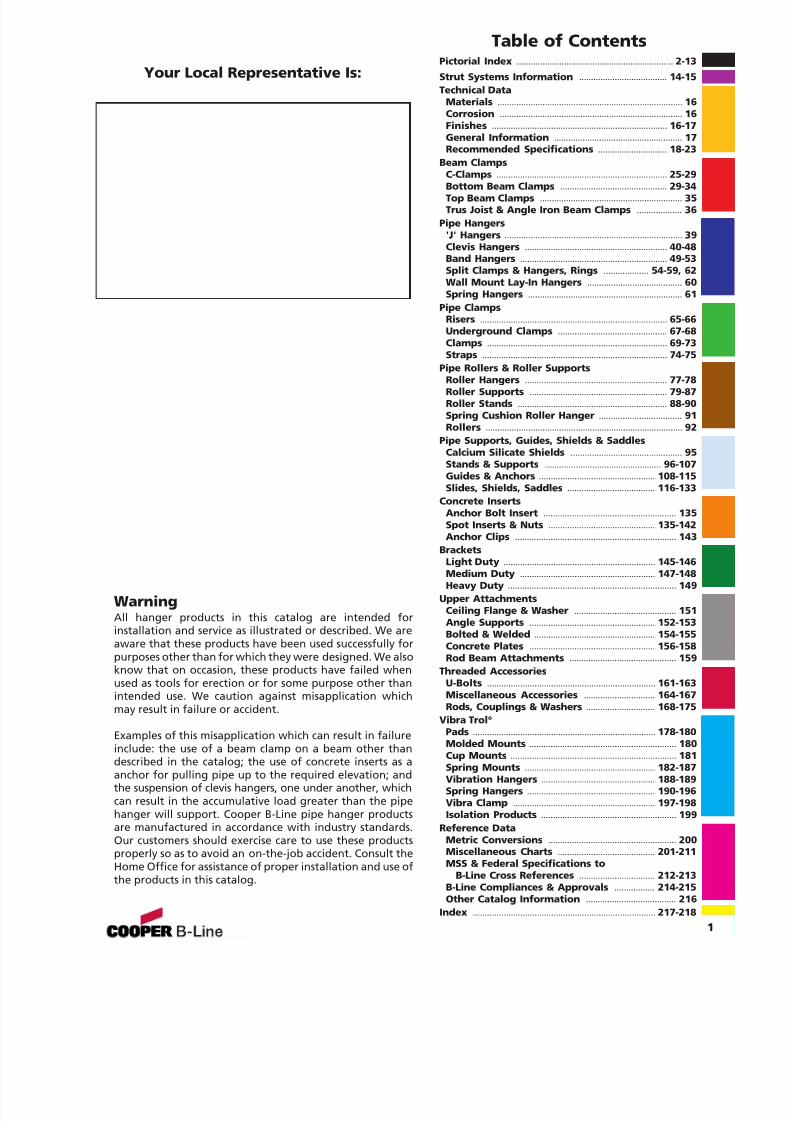
Table of ContentsPictorial Index .................................................................. 2-13
Strut Systems Information ..................................... 14-15Technical Data
Materials .............................................................................. 16Corrosion ............................................................................. 16Finishes .......................................................................... 16-17General Information ...................................................... 17Recommended Specifications ............................. 18-23
Beam ClampsC-Clamps ........................................................................ 25-29Bottom Beam Clamps ............................................. 29-34Top Beam Clamps ............................................................ 35Trus Joist & Angle Iron Beam Clamps ................... 36
Pipe Hangers'J' Hangers ........................................................................... 39Clevis Hangers ............................................................ 40-48Band Hangers .............................................................. 49-53Split Clamps & Hangers, Rings ................... 54-59, 62Wall Mount Lay-In Hangers ........................................ 60Spring Hangers ................................................................. 61
Pipe ClampsRisers ............................................................................... 65-66Underground Clamps .............................................. 67-68Clamps ............................................................................ 69-73Straps .............................................................................. 74-75
Pipe Rollers & Roller SupportsRoller Hangers ............................................................ 77-78Roller Supports .......................................................... 79-87Roller Stands ............................................................... 88-90Spring Cushion Roller Hanger ................................... 91Rollers ................................................................................... 92
Pipe Supports, Guides, Shields & SaddlesCalcium Silicate Shields ............................................... 95Stands & Supports ................................................. 96-107Guides & Anchors ................................................. 108-115Slides, Shields, Saddles ..................................... 116-133
Concrete InsertsAnchor Bolt Insert ........................................................ 135Spot Inserts & Nuts ............................................. 135-142Anchor Clips .................................................................... 143
BracketsLight Duty ................................................................ 145-146Medium Duty ......................................................... 147-148Heavy Duty ....................................................................... 149
Upper AttachmentsCeiling Flange & Washer ........................................... 151Angle Supports ..................................................... 152-153Bolted & Welded ................................................... 154-155Concrete Plates ..................................................... 156-158Rod Beam Attachments ............................................. 159
Threaded AccessoriesU-Bolts ....................................................................... 161-163Miscellaneous Accessories .............................. 164-167Rods, Couplings & Washers ............................. 168-175
Vibra Trol ®
Pads ............................................................................. 178-180Molded Mounts .............................................................. 180Cup Mounts ...................................................................... 181Spring Mounts ....................................................... 182-187Vibration Hangers ................................................ 188-189Spring Hangers ...................................................... 190-196Vibra Clamp ............................................................ 197-198Isolation Products ......................................................... 199
Reference DataMetric Conversions ...................................................... 200Miscellaneous Charts ......................................... 201-211MSS & Federal Specifications to
B-Line Cross References ................................ 212-213B-Line Compliances & Approvals ................. 214-215Other Catalog Information ...................................... 216
Index ............................................................................. 217-218
1
7/18/2019 PH Pipe Hanger Catalog
http://slidepdf.com/reader/full/ph-pipe-hanger-catalog 4/224
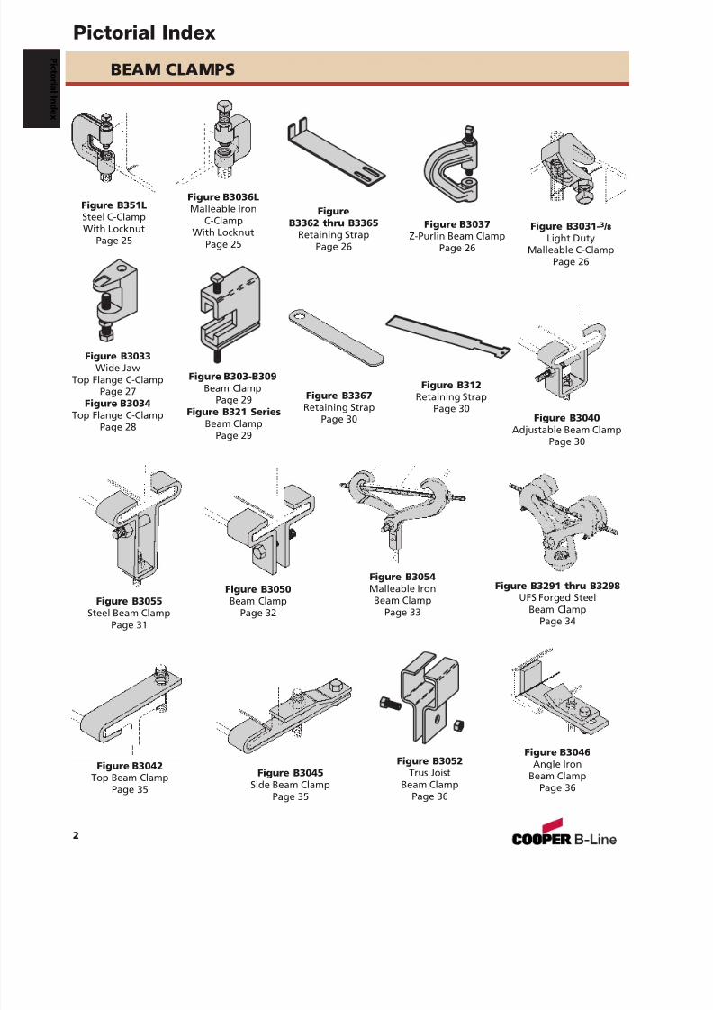
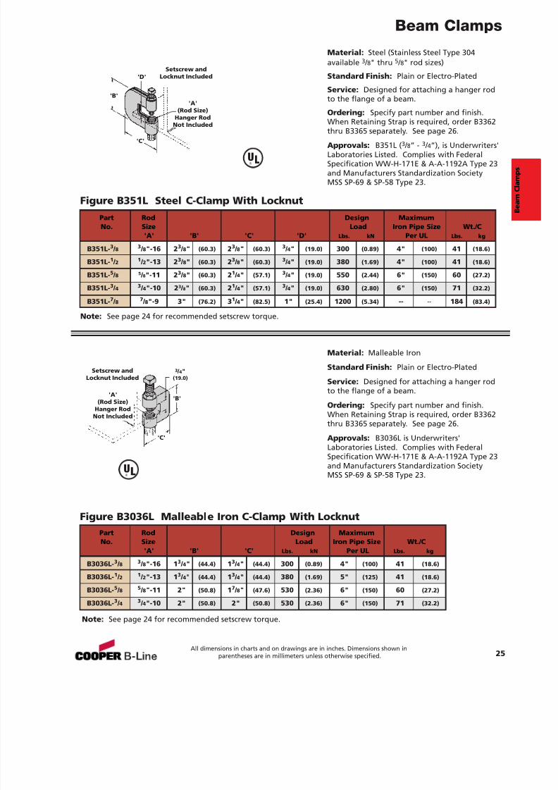
Figure B351LSteel C-ClampWith Locknut
Page 25
Figure B3036LMalleable Iron
C-ClampWith Locknut
Page 25
FigureB3362 thru B3365
Retaining StrapPage 26
Figure B3031- 3 / 8Light Duty
Malleable C-ClampPage 26
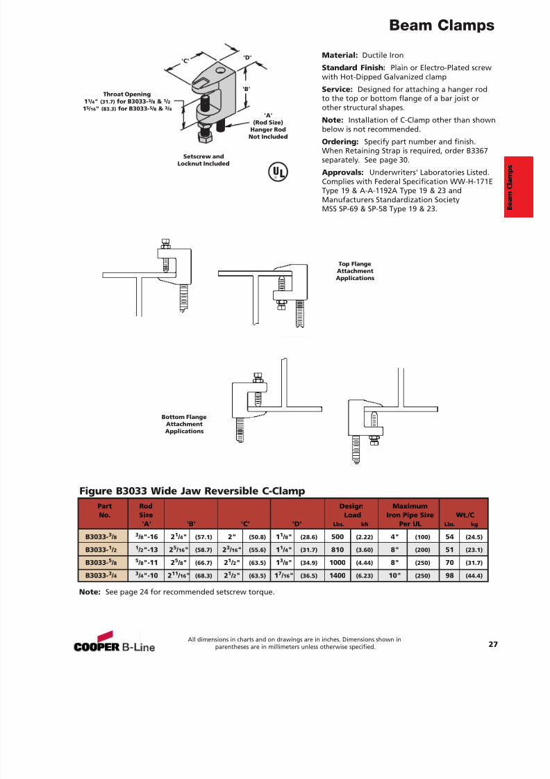
Figure B3033Wide Jaw
Top Flange C-ClampPage 27
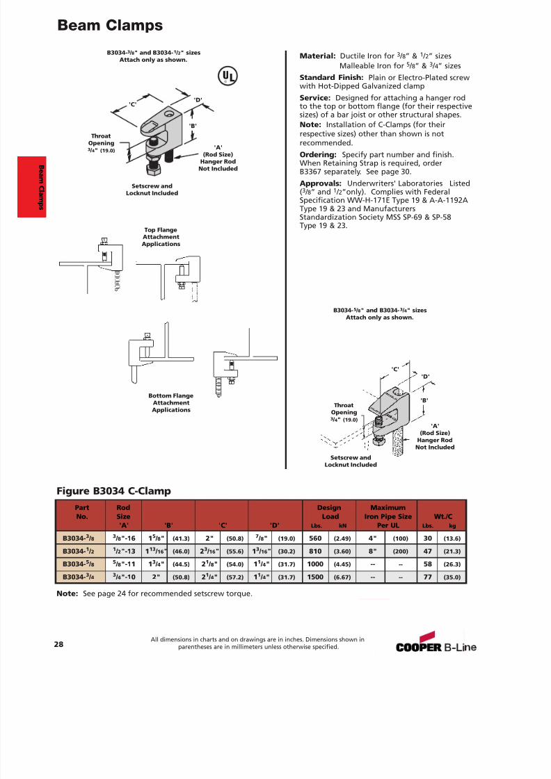
Figure B3034Top Flange C-Clamp
Page 28
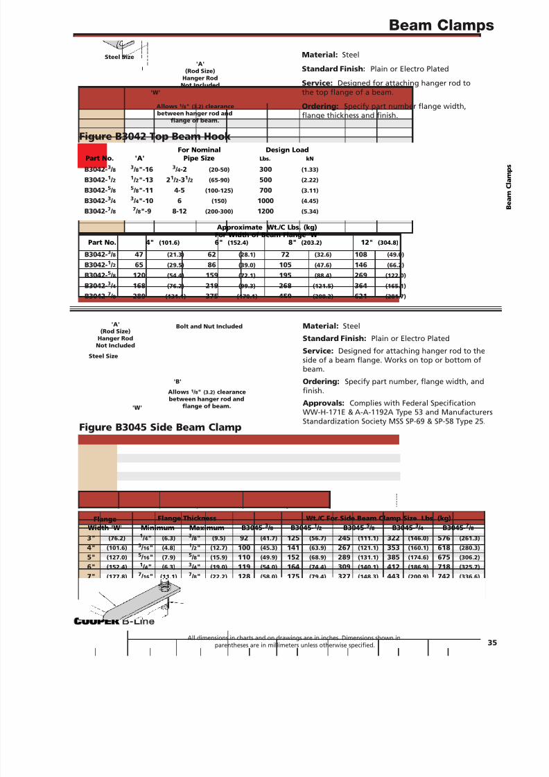
Figure B3042Top Beam Clamp
Page 35
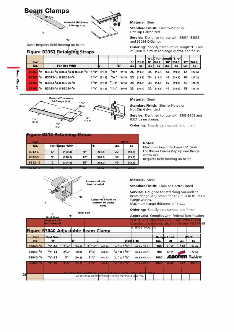
Figure B312Retaining Strap
Page 30
Figure B3046Angle Iron
Beam ClampPage 36
Figure B3050Beam Clamp
Page 32
Figure B3045Side Beam Clamp
Page 35
Figure B3037Z-Purlin Beam Clamp
Page 26
Figure B3052Trus Joist
Beam ClampPage 36
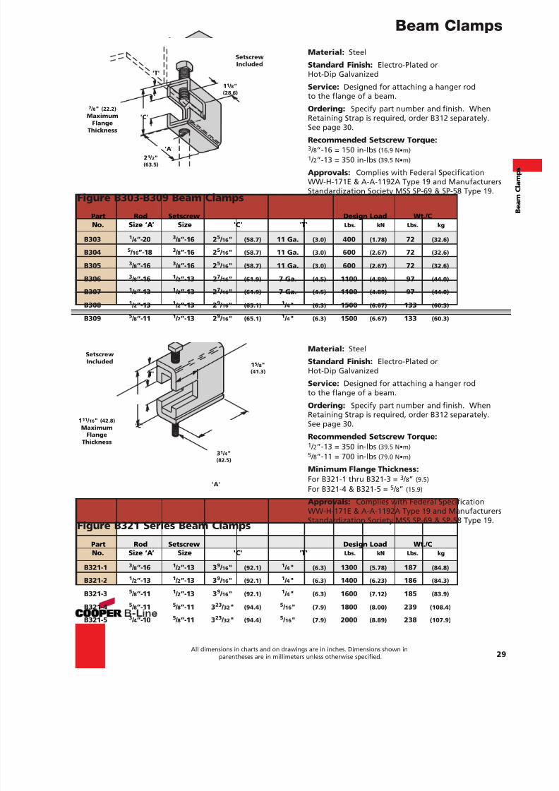
Figure B303-B309Beam Clamp
Page 29Figure B321 Series
Beam ClampPage 29
Figure B3367Retaining Strap
Page 30
Figure B3291 thru B3298UFS Forged Steel
Beam ClampPage 34
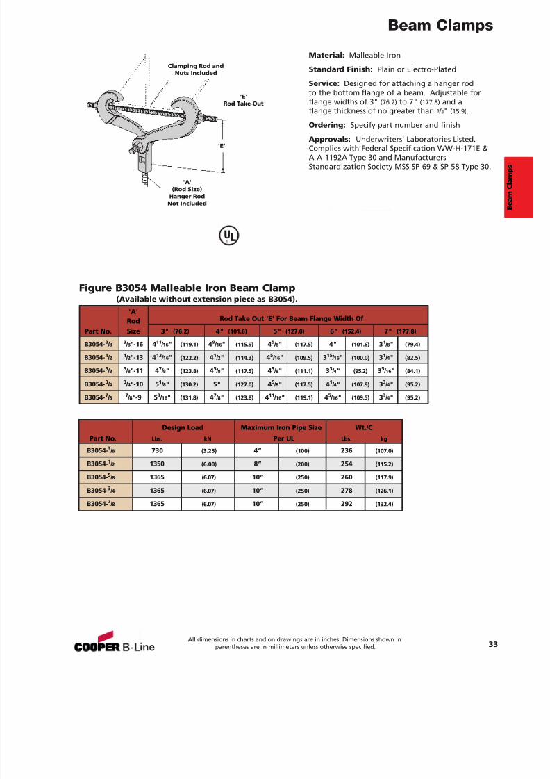
Figure B3054Malleable IronBeam Clamp
Page 33
BEAM CLAMPS
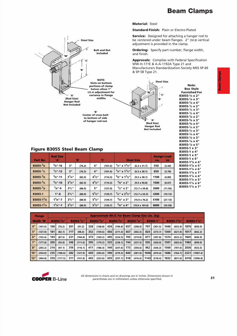
Figure B3055Steel Beam Clamp
Page 31
Pictorial Index
2
P i c t or i al I nd ex
Figure B3040Adjustable Beam Clamp
Page 30
7/18/2019 PH Pipe Hanger Catalog
http://slidepdf.com/reader/full/ph-pipe-hanger-catalog 5/224
N New Dura-Copper Finish3 New Dura-Green Finish
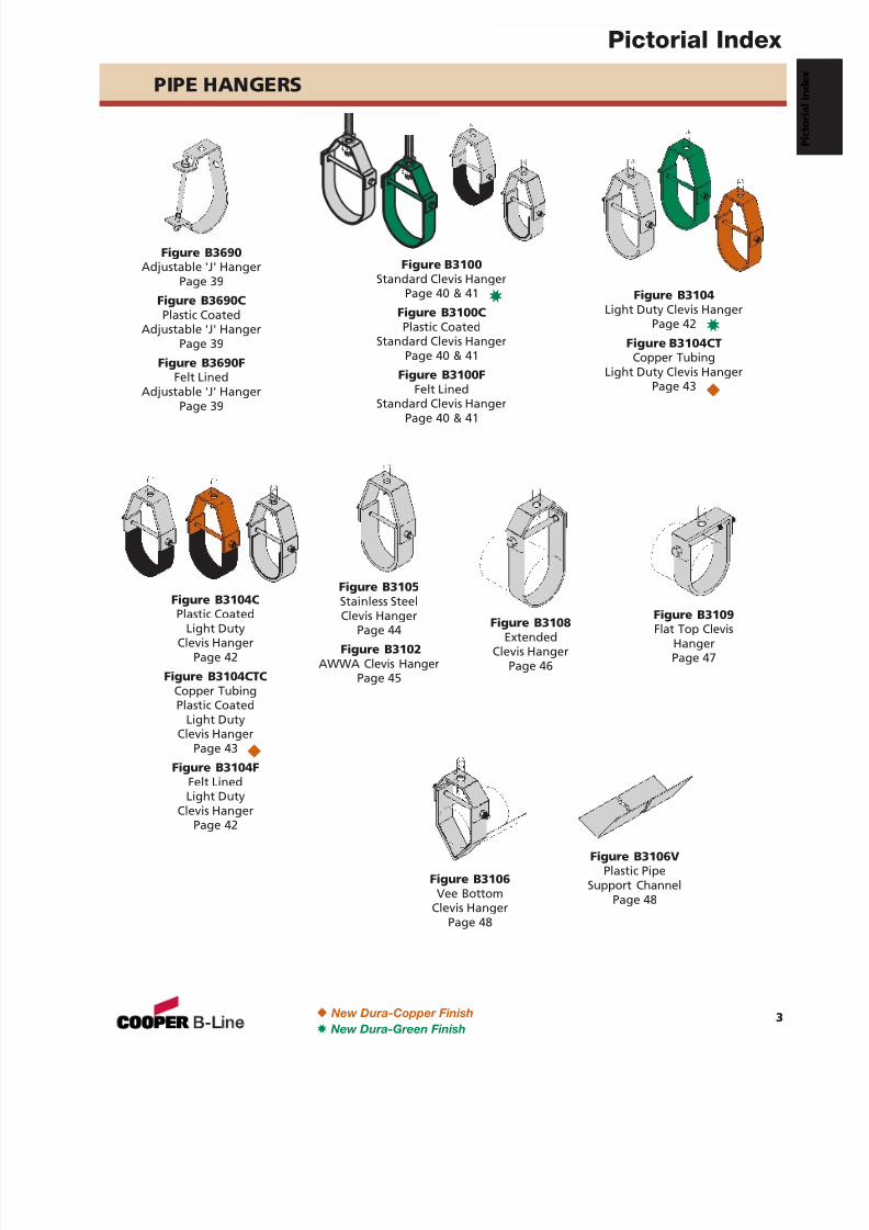
Figure B3106Vee Bottom
Clevis HangerPage 48
Figure B3106VPlastic Pipe
Support ChannelPage 48
Figure B3108Extended
Clevis HangerPage 46
Figure B3109Flat Top Clevis
HangerPage 47
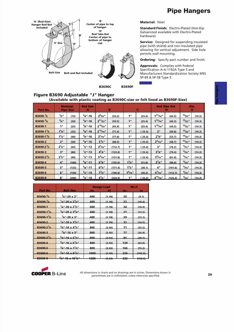
Figure B3690Adjustable 'J' Hanger
Page 39
Figure B3690CPlastic Coated
Adjustable 'J' HangerPage 39
Figure B3690FFelt Lined
Adjustable 'J' Hanger
Page 39
Figure B3104Light Duty Clevis Hanger
Page 42
Figure B3104CTCopper Tubing
Light Duty Clevis HangerPage 43
Figure B3104CPlastic Coated
Light DutyClevis Hanger
Page 42
Figure B3104CTCCopper TubingPlastic Coated
Light DutyClevis Hanger
Page 43
Figure B3104FFelt LinedLight Duty
Clevis HangerPage 42
Figure B3100Standard Clevis Hanger
Page 40 & 41
Figure B3100CPlastic Coated
Standard Clevis HangerPage 40 & 41
Figure B3100FFelt Lined
Standard Clevis HangerPage 40 & 41
Figure B3105Stainless SteelClevis Hanger
Page 44
Figure B3102AWWA Clevis Hanger
Page 45
PIPE HANGERS
N
3
3
N
Pictorial Index
3
7/18/2019 PH Pipe Hanger Catalog
http://slidepdf.com/reader/full/ph-pipe-hanger-catalog 6/224
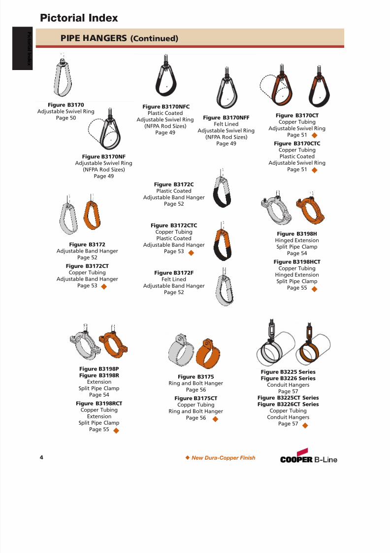
Figure B3225 SeriesFigure B3226 Series
Conduit HangersPage 57
Figure B3225CT SeriesFigure B3226CT Series
Copper TubingConduit Hangers
Page 57
PIPE HANGERS (Continued)
N
Figure B3198HHinged ExtensionSplit Pipe Clamp
Page 54
Figure B3198HCTCopper Tubing
Hinged ExtensionSplit Pipe Clamp
Page 55 N
Figure B3198PFigure B3198R
ExtensionSplit Pipe Clamp
Page 54
Figure B3198RCTCopper Tubing
ExtensionSplit Pipe Clamp
Page 55 N
Figure B3175Ring and Bolt Hanger
Page 56
Figure B3175CTCopper Tubing
Ring and Bolt HangerPage 56 N
Figure B3170CTCopper Tubing
Adjustable Swivel RingPage 51
Figure B3170CTCCopper TubingPlastic Coated
Adjustable Swivel RingPage 51
Figure B3172Adjustable Band Hanger
Page 52
Figure B3172CT
Copper TubingAdjustable Band HangerPage 53
Figure B3172CPlastic Coated
Adjustable Band HangerPage 52
Figure B3172CTCCopper TubingPlastic Coated
Adjustable Band HangerPage 53
Figure B3172FFelt LinedAdjustable Band Hanger
Page 52
N
N
N
N
Figure B3170Adjustable Swivel Ring
Page 50
Figure B3170NFAdjustable Swivel Ring
(NFPA Rod Sizes)Page 49
Figure B3170NFCPlastic Coated
Adjustable Swivel Ring(NFPA Rod Sizes)
Page 49
Figure B3170NFFFelt Lined
Adjustable Swivel Ring(NFPA Rod Sizes)
Page 49
N New Dura-Copper Finish
Pictorial Index
4
P i c t or i al I nd ex
7/18/2019 PH Pipe Hanger Catalog
http://slidepdf.com/reader/full/ph-pipe-hanger-catalog 7/224
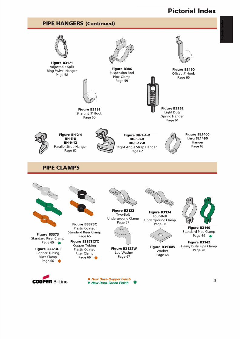
PIPE CLAMPS
Figure B3373Standard Riser Clamp
Page 65
Figure B3373CTCopper Tubing
Riser ClampPage 66
Figure B3373CPlastic Coated
Standard Riser ClampPage 65
Figure B3373CTCCopper TubingPlastic Coated
Riser ClampPage 66
NN
Figure B3132Two-Bolt
Underground ClampPage 67
Figure B3132WLug Washer
Page 67
Figure B3134WWasherPage 68
Figure B3134Four-Bolt
Underground Clamp
Page 68 Figure B3140Standard Pipe Clamp
Page 69
Figure B3142Heavy Duty Pipe Clamp
Page 70
3
3
3
PIPE HANGERS (Continued)
Figure BH-2-4BH-5-8
BH-9-12Parallel Strap Hanger
Page 62
Figure BH-2-4-RBH-5-8-R
BH-9-12-RRight Angle Strap Hanger
Page 62
Figure BL1400thru BL1490
HangerPage 62
Figure B3191Straight 'J' Hook
Page 60
Figure B386Suspension Rod
Pipe ClampPage 59
Figure B3171Adjustable Split
Ring Swivel HangerPage 58
Figure B3262Light Duty
Spring HangerPage 61
Figure B3190Offset 'J' Hook
Page 60
N New Dura-Copper Finish3 New Dura-Green Finish
Pictorial Index
5
7/18/2019 PH Pipe Hanger Catalog
http://slidepdf.com/reader/full/ph-pipe-hanger-catalog 8/224
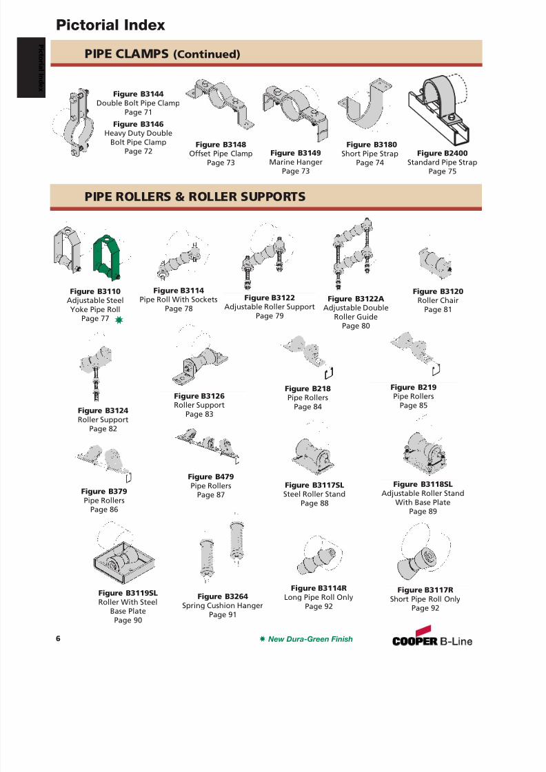
Figure B3148Offset Pipe Clamp
Page 73Figure B3149Marine Hanger
Page 73
Figure B3180Short Pipe Strap
Page 74
Figure B3110Adjustable SteelYoke Pipe Roll
Page 77
Figure B3120Roller Chair
Page 81
Figure B3114Pipe Roll With Sockets
Page 78Figure B3122
Adjustable Roller SupportPage 79
Figure B3124Roller Support
Page 82
Figure B218Pipe Rollers
Page 84
Figure B219Pipe Rollers
Page 85Figure B3126Roller Support
Page 83
PIPE CLAMPS (Continued)
PIPE ROLLERS & ROLLER SUPPORTS
Figure B2400Standard Pipe Strap
Page 75
Figure B3144Double Bolt Pipe Clamp
Page 71
Figure B3146Heavy Duty DoubleBolt Pipe Clamp
Page 72
Figure B379Pipe Rollers
Page 86
Figure B479Pipe Rollers
Page 87Figure B3118SL
Adjustable Roller StandWith Base Plate
Page 89
Figure B3119SLRoller With Steel
Base PlatePage 90
Figure B3117SLSteel Roller Stand
Page 88
Figure B3114RLong Pipe Roll Only
Page 92Figure B3264
Spring Cushion HangerPage 91
Figure B3122AAdjustable Double
Roller GuidePage 80
3
3 New Dura-Green Finish
Pictorial Index
6
P i c t or i al I nd ex
Figure B3117RShort Pipe Roll Only
Page 92
7/18/2019 PH Pipe Hanger Catalog
http://slidepdf.com/reader/full/ph-pipe-hanger-catalog 9/224
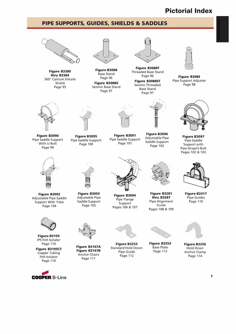
Figure B3088Base Stand
Page 96
Figure B3088SSeismic Base Stand
Page 97
Figure B3088TThreaded Base Stand
Page 96
Figure B3088STSeismic Threaded
Base StandPage 97
Figure B3089Pipe Support Adjuster
Page 98
Figure B3090Pipe Saddle Support
With U-BoltPage 99
Figure B3095Pipe Saddle Support
Page 100
Figure B3091Pipe Saddle Support
Page 101
Figure B3096Adjustable PipeSaddle Support
Page 102
Figure B3092Adjustable Pipe Saddle
Support With YokePage 104
Figure B3093Adjustable PipeSaddle Support
Page 105
Figure B3281thru B3287
Pipe AlignmentGuide
Pages 108 & 109
PIPE SUPPORTS, GUIDES, SHIELDS & SADDLES
Figure B3380thru B3384
360° Calcium SilicateShield
Page 95
Figure B3097Pipe Saddle
Support withPipe Strap/U-BoltPages 102 & 103
Figure B3094Pipe Flange
SupportPages 106 & 107
Figure B3147AFigure B3147BAnchor Chairs
Page 111
Figure B3195IPS Felt Isolator
Page 110
Figure B3195CTCopper Tubing
Felt IsolatorPage 110
Figure B2417Pipe Guides
Page 110
Figure B3252Standard Hold-Down
Pipe GuidePage 112
Figure B3253Base PlatePage 113
Figure B3256Hold-Down
Anchor ClampPage 114
Pictorial Index
7
7/18/2019 PH Pipe Hanger Catalog
http://slidepdf.com/reader/full/ph-pipe-hanger-catalog 10/224
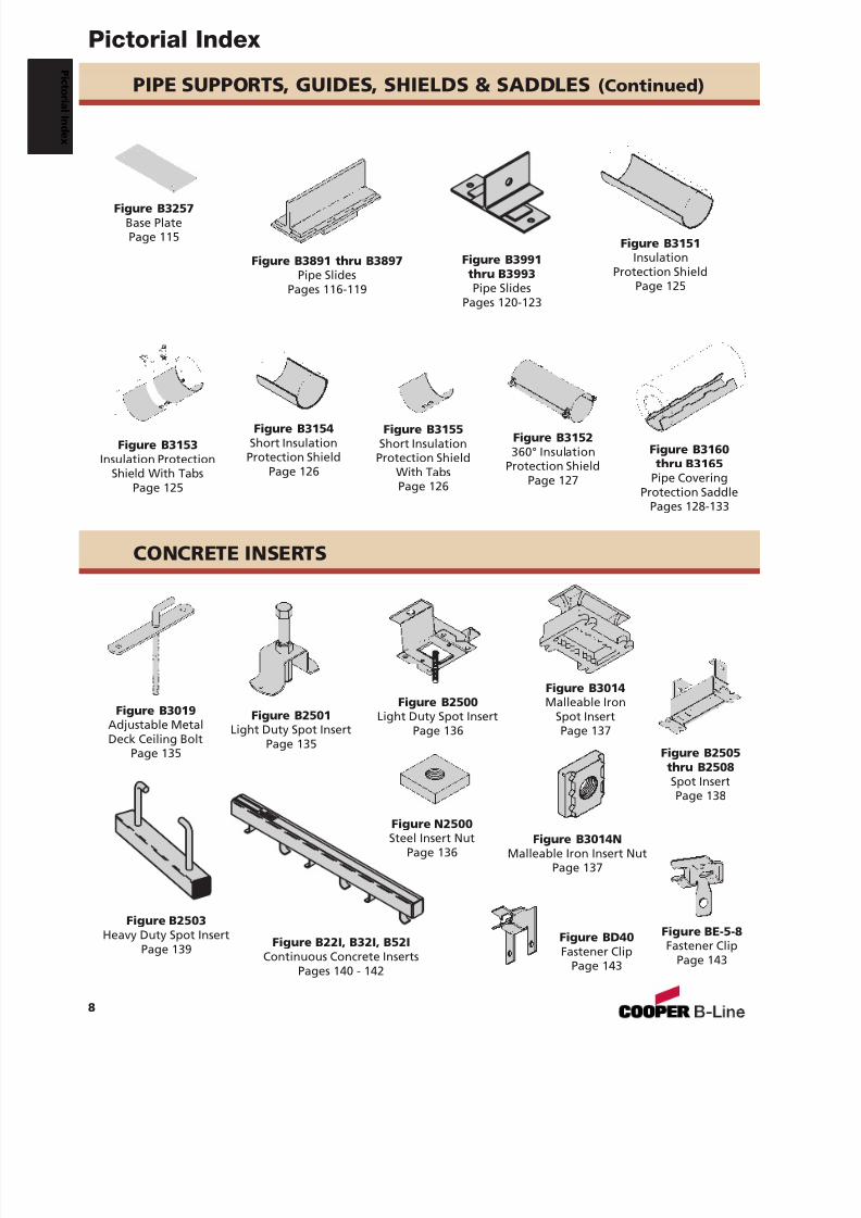
PIPE SUPPORTS, GUIDES, SHIELDS & SADDLES (Continued)
Figure B3257Base PlatePage 115 Figure B3151
InsulationProtection Shield
Page 125
Figure B3891 thru B3897Pipe Slides
Pages 116-119
Figure B3153Insulation Protection
Shield With TabsPage 125
Figure B3155Short Insulation
Protection ShieldWith TabsPage 126
Figure B3160thru B3165
Pipe CoveringProtection Saddle
Pages 128-133
Figure B3991thru B3993Pipe Slides
Pages 120-123
Figure B3154Short Insulation
Protection ShieldPage 126
Figure B3152360° Insulation
Protection ShieldPage 127
Figure BE-5-8Fastener Clip
Page 143
Figure B2500Light Duty Spot Insert
Page 136
Figure N2500Steel Insert Nut
Page 136
Figure B2501Light Duty Spot Insert
Page 135
Figure B3014Malleable Iron
Spot InsertPage 137
Figure B3014NMalleable Iron Insert Nut
Page 137
CONCRETE INSERTS
Figure B2503Heavy Duty Spot Insert
Page 139 Figure B22I, B32I, B52IContinuous Concrete Inserts
Pages 140 - 142
Figure B3019Adjustable MetalDeck Ceiling Bolt
Page 135 Figure B2505thru B2508Spot InsertPage 138
Figure BD40Fastener Clip
Page 143
Pictorial Index
8
P i c t or i al I nd ex
7/18/2019 PH Pipe Hanger Catalog
http://slidepdf.com/reader/full/ph-pipe-hanger-catalog 11/224
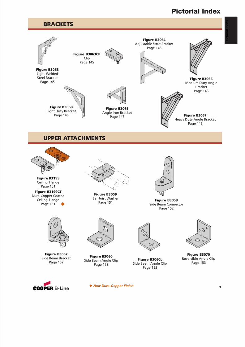
BRACKETS
Figure B3063Light WeldedSteel Bracket
Page 145
Figure B3063CPClip
Page 145
Figure B3065Angle Iron Bracket
Page 147
Figure B3064Adjustable Strut Bracket
Page 146
UPPER ATTACHMENTS
Figure B3068Light Duty Bracket
Page 146
Figure B3199Ceiling Flange
Page 151
Figure B3199CTDura-Copper Coated
Ceiling FlangePage 151
Figure B3058Side Beam Connector
Page 152
Figure B3059Bar Joist Washer
Page 151
Figure B3062Side Beam Bracket
Page 152
Figure B3060Side Beam Angle Clip
Page 153
Figure B3070Reversible Angle Clip
Page 153Figure B3060L
Side Beam Angle ClipPage 153
N
N New Dura-Copper Finish
Pictorial Index
9
Figure B3067Heavy Duty Angle Bracket
Page 149
Figure B3066Medium Duty Angle
BracketPage 148
7/18/2019 PH Pipe Hanger Catalog
http://slidepdf.com/reader/full/ph-pipe-hanger-catalog 12/224
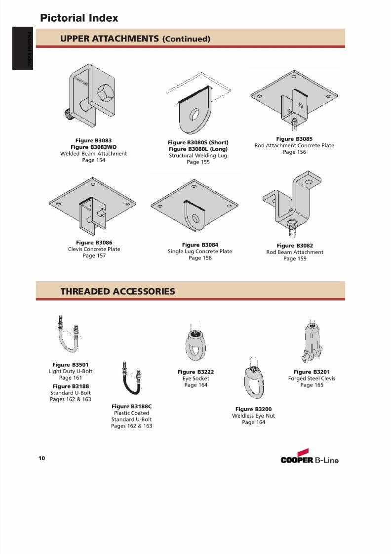
UPPER ATTACHMENTS (Continued)
Figure B3084Single Lug Concrete Plate
Page 158
Figure B3085Rod Attachment Concrete Plate
Page 156
Figure B3086Clevis Concrete Plate
Page 157
Figure B3082Rod Beam Attachment
Page 159
Figure B3080S (Short)Figure B3080L (Long)Structural Welding Lug
Page 155
Figure B3083Figure B3083WO
Welded Beam AttachmentPage 154
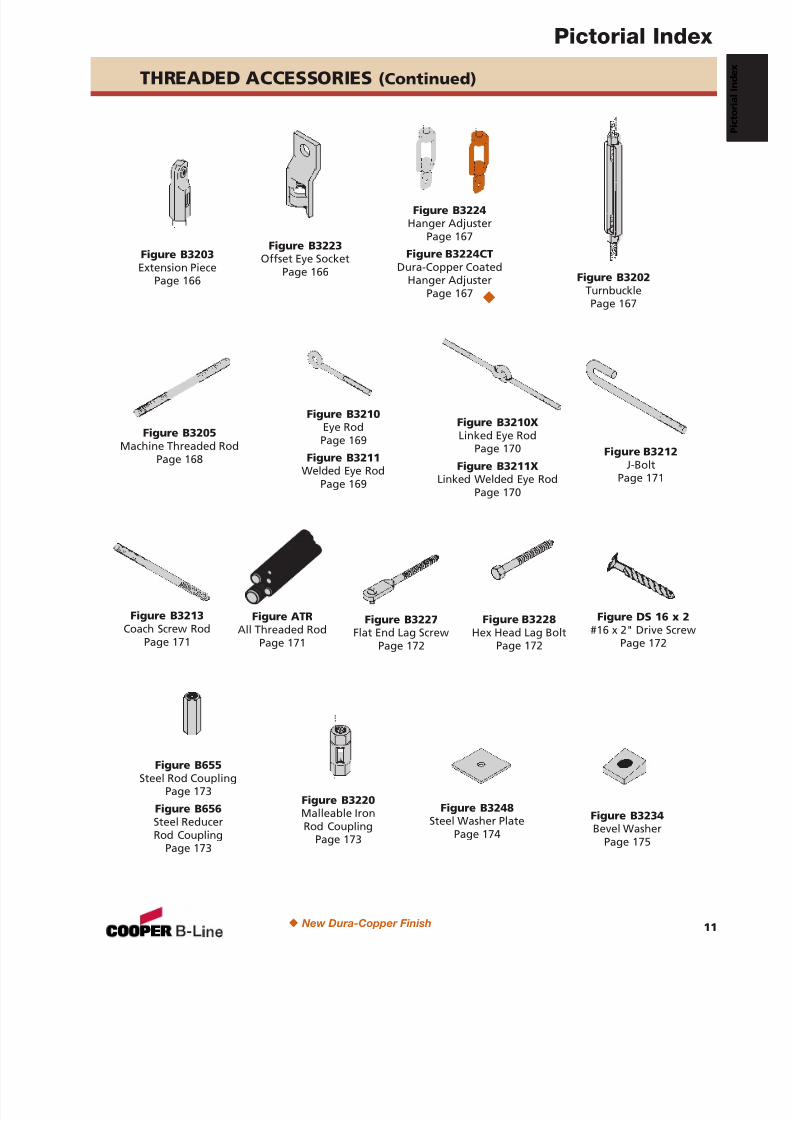
THREADED ACCESSORIES
Figure B3501Light Duty U-BoltPage 161
Figure B3188Standard U-BoltPages 162 & 163
Figure B3188CPlastic Coated
Standard U-BoltPages 162 & 163
Figure B3222Eye SocketPage 164
Figure B3201Forged Steel Clevis
Page 165
Figure B3200Weldless Eye Nut
Page 164
Pictorial Index
10
P i c t or i al I nd ex
7/18/2019 PH Pipe Hanger Catalog
http://slidepdf.com/reader/full/ph-pipe-hanger-catalog 13/224
Figure B3210Eye RodPage 169
Figure B3211Welded Eye Rod
Page 169
Figure B3210XLinked Eye Rod
Page 170
Figure B3211XLinked Welded Eye Rod
Page 170
Figure B3223Offset Eye Socket
Page 166
Figure B3203Extension Piece
Page 166 Figure B3202TurnbucklePage 167
Figure B3220Malleable IronRod Coupling
Page 173
Figure B655Steel Rod Coupling
Page 173
Figure B656Steel ReducerRod Coupling
Page 173
Figure B3224Hanger Adjuster
Page 167
Figure B3224CTDura-Copper Coated
Hanger AdjusterPage 167
Figure B3205Machine Threaded Rod
Page 168
Figure B3228Hex Head Lag Bolt
Page 172
Figure DS 16 x 2#16 x 2" Drive Screw
Page 172
Figure B3212J-Bolt
Page 171
Figure B3213Coach Screw Rod
Page 171
Figure B3227Flat End Lag Screw
Page 172
THREADED ACCESSORIES (Continued)
Figure ATRAll Threaded Rod
Page 171
N
Figure B3234Bevel Washer
Page 175
Figure B3248Steel Washer Plate
Page 174
N New Dura-Copper Finish
Pictorial Index
11
7/18/2019 PH Pipe Hanger Catalog
http://slidepdf.com/reader/full/ph-pipe-hanger-catalog 14/224
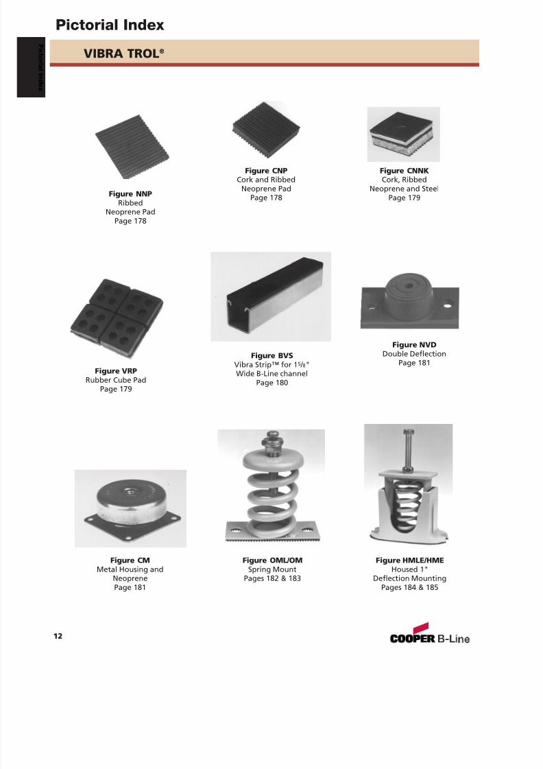
VIBRA TROL ®
Figure NNPRibbed
Neoprene PadPage 178
Figure VRP
Rubber Cube PadPage 179
Figure CNNKCork, Ribbed
Neoprene and SteelPage 179
Figure CNPCork and Ribbed
Neoprene PadPage 178
Figure BVSVibra Strip™ for 1 5 / 8"Wide B-Line channel
Page 180
Figure NVDDouble Deflection
Page 181
Figure OML/OMSpring Mount
Pages 182 & 183
Figure HMLE/HMEHoused 1"
Deflection MountingPages 184 & 185
Figure CMMetal Housing and
NeoprenePage 181
Pictorial Index
12
P i c t or i al I nd ex
7/18/2019 PH Pipe Hanger Catalog
http://slidepdf.com/reader/full/ph-pipe-hanger-catalog 15/224
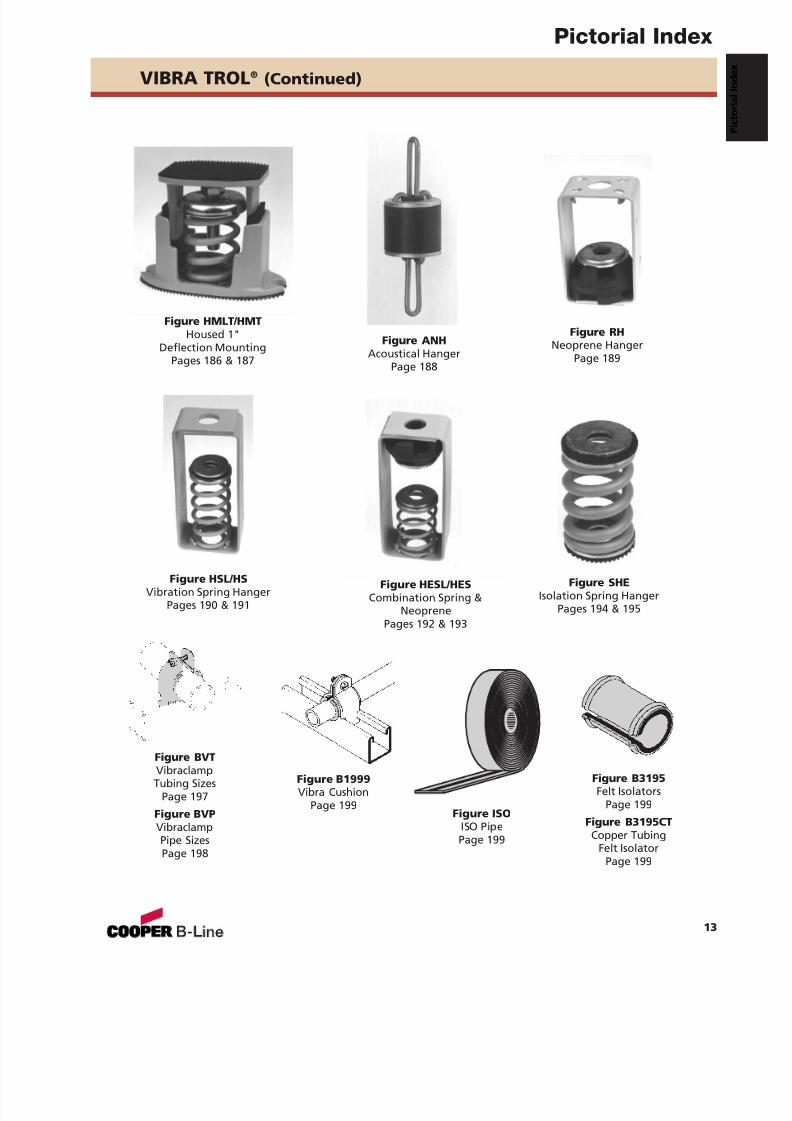
Figure SHEIsolation Spring Hanger
Pages 194 & 195
VIBRA TROL ® (Continued)
Figure B3195Felt Isolators
Page 199
Figure B3195CTCopper Tubing
Felt IsolatorPage 199
Figure HSL/HSVibration Spring Hanger
Pages 190 & 191
Figure RHNeoprene Hanger
Page 189
Figure HESL/HESCombination Spring &
NeoprenePages 192 & 193
Figure ANHAcoustical Hanger
Page 188
Figure HMLT/HMTHoused 1"
Deflection MountingPages 186 & 187
Figure BVTVibraclampTubing Sizes
Page 197
Figure BVPVibraclampPipe SizesPage 198
Figure B1999Vibra Cushion
Page 199Figure ISO
ISO PipePage 199
Pictorial Index
13
7/18/2019 PH Pipe Hanger Catalog
http://slidepdf.com/reader/full/ph-pipe-hanger-catalog 16/224
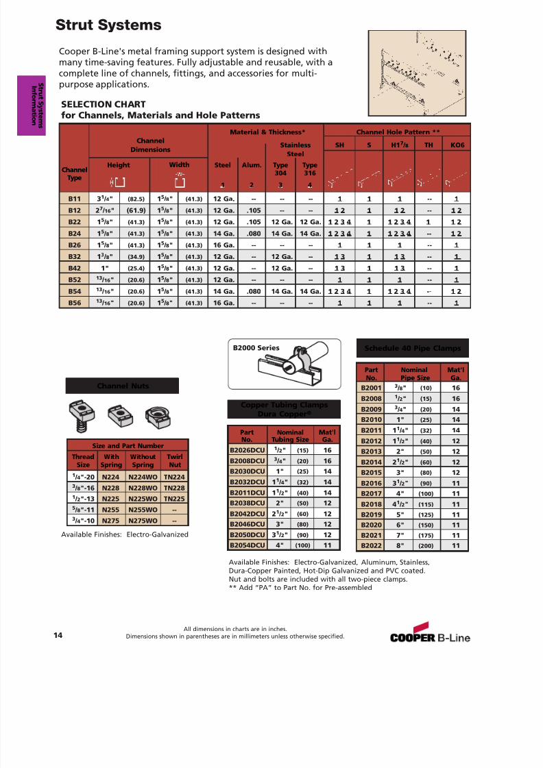
Cooper B-Line's metal framing support system is designed withmany time-saving features. Fully adjustable and reusable, with acomplete line of channels, fittings, and accessories for multi-purpose applications.
SELECTION CHARTfor Channels, Materials and Hole Patterns
Material & Thickness* Channel Hole Pattern **Channel
Stainless SH S H1 7 / 8 TH KO6Dimensions
Steel
B11 3 1 / 4" (82.5) 1 5 / 8" (41.3) 12 Ga. -- -- -- 1 1 1 -- 1
B12 2 7 / 16 " (61.9) 1 5 / 8" (41.3) 12 Ga. .105 -- -- 1 2 1 1 2 -- 1 2
B22 1 5 / 8" (41.3) 1 5 / 8" (41.3) 12 Ga. .105 12 Ga. 12 Ga. 1 2 3 4 1 1 2 3 4 1 1 2
B24 1 5 / 8" (41.3) 1 5 / 8" (41.3) 14 Ga. .080 14 Ga. 14 Ga. 1 2 3 4 1 1 2 3 4 -- 1 2
B26 1 5 / 8" (41.3) 1 5 / 8" (41.3) 16 Ga. -- -- -- 1 1 1 -- 1
B32 1 3 / 8" (34.9) 1 5 / 8" (41.3) 12 Ga. -- 12 Ga. -- 1 3 1 1 3 -- 1
B42 1" (25.4) 1 5 / 8" (41.3) 12 Ga. -- 12 Ga. -- 1 3 1 1 3 -- 1
B52 13 / 16 " (20.6) 1 5 / 8" (41.3) 12 Ga. -- -- -- 1 1 1 -- 1
B54 13 / 16 " (20.6) 1 5 / 8" (41.3) 14 Ga. .080 14 Ga. 14 Ga. 1 2 3 4 1 1 2 3 4 -- 1 2
B56 13 / 16 " (20.6) 1 5 / 8" (41.3) 16 Ga. -- -- -- 1 1 1 -- 1
ChannelType
Steel
1
Alum.
2
Type304
3
Type316
4
Height Width
Channel Nuts
Size and Part Number
Thread With Without TwirlSize Spring Spring Nut
1 / 4"-20 N224 N224WO TN2243 / 8"-16 N228 N228WO TN2281 / 2"-13 N225 N225WO TN225
5 / 8"-11 N255 N255WO --3 / 4"-10 N275 N275WO --
Schedule 40 Pipe Clamps
Copper Tubing ClampsDura Copper ®
Available Finishes: Electro-Galvanized, Aluminum, Stainless,Dura-Copper Painted, Hot-Dip Galvanized and PVC coated.Nut and bolts are included with all two-piece clamps.** Add “PA” to Part No. for Pre-assembled
Available Finishes: Electro-Galvanized
B2000 Series
Part Nominal Mat'lNo. Tubing Size Ga.
B2026DCU 1 / 2" (15) 16
B2008DCU 3 / 4" (20) 16B2030DCU 1" (25) 14
B2032DCU 1 1 / 4" (32) 14
B2011DCU 1 1 / 2" (40) 14B2038DCU 2" (50) 12
B2042DCU 2 1 / 2" (60) 12B2046DCU 3" (80) 12
B2050DCU 3 1 / 2" (90) 12B2054DCU 4" (100) 11
Part Nominal Mat'l
No. Pipe Size Ga.B2001 3 / 8" (10) 16
B2008 1 / 2" (15) 16
B2009 3 / 4" (20) 14B2010 1" (25) 14
B2011 1 1 / 4" (32) 14
B2012 1 1 / 2" (40) 12B2013 2" (50) 12
B2014 2 1 / 2" (60) 12B2015 3" (80) 12
B2016 3 1 / 2" (90) 11B2017 4" (100) 11
B2018 4 1 / 2" (115) 11B2019 5" (125) 11B2020 6" (150) 11B2021 7" (175) 11B2022 8" (200) 11
Strut Systems
14
S t r ut S ys t ems
m
All dimensions in charts are in inches.Dimensions shown in parentheses are in millimeters unless otherwise specified.
7/18/2019 PH Pipe Hanger Catalog
http://slidepdf.com/reader/full/ph-pipe-hanger-catalog 17/224
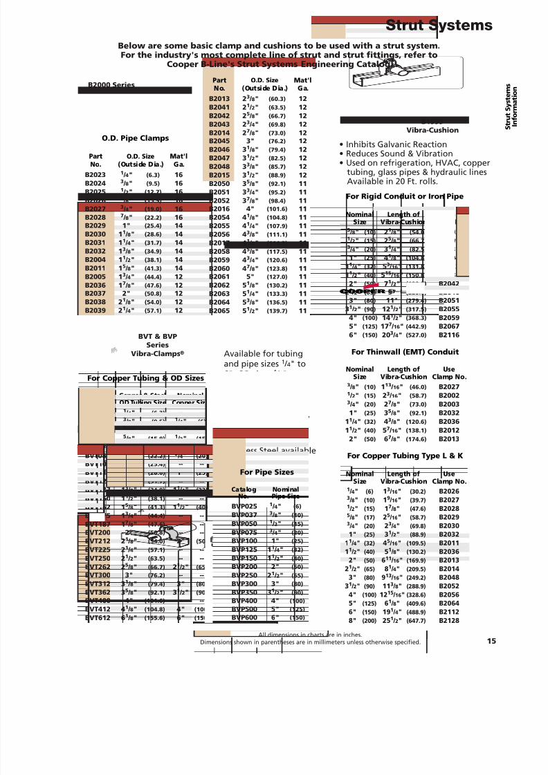
Below are some basic clamp and cushions to be used with a strut system.For the industry's most complete line of strut and strut fittings, refer to
Cooper B-Line's Strut Systems Engineering Catalog.
O.D. Pipe Clamps
For Rigid Conduit or Iron Pipe
B1999Vibra-Cushion
• Inhibits Galvanic Reaction• Reduces Sound & Vibration• Used on refrigeration, HVAC, copper
tubing, glass pipes & hydraulic linesAvailable in 20 Ft. rolls.
B-LINEB-LINE
BV P150BVP150
1 1 / 2” I.P1 1/2” I.P
BVT & BVPSeries
Vibra-Clamps ® Available for tubingand pipe sizes 1 / 4" to6", OD sizes 1 / 4" to
65 / 8". Easy one toolinstallation, dampensvibration and noise,secures tubing firmly,and protects againstgalvanic reaction.
Stainless Steel available
Part O.D. Size Mat'lNo. (Outside Dia.) Ga.
B2023 1 / 4" (6.3) 16B2024 3 / 8" (9.5) 16B2025 1 / 2" (12.7) 16B2026 5 / 8" (15.9) 16B2027 3 / 4" (19.0) 16B2028 7 / 8" (22.2) 16B2029 1" (25.4) 14B2030 1 1 / 8" (28.6) 14B2031 1 1 / 4" (31.7) 14B2032 1 3 / 8" (34.9) 14B2004 1 1 / 2" (38.1) 14B2011 1 5 / 8" (41.3) 14B2005 1 3 / 4" (44.4) 12B2036 1 7 / 8" (47.6) 12B2037 2" (50.8) 12B2038 2 1 / 8" (54.0) 12B2039 2 1 / 4" (57.1) 12
Nominal Length of UseSize Vibra-Cushion Clamp No.
3 / 8" (10) 2 1 / 8" (54.0) B20021 / 2" (15) 2 5 / 8" (66.7) B20093 / 4" (20) 3 1 / 4" (82.5) B20311" (25) 4 1 / 8" (104.8) B2004
1 1 / 4" (32) 5 3 / 16 " (131.8) B20121 1 / 2" (40) 5 15 / 16 " (150.8) B2038
2" (50) 7 1 / 2" (190.5) B20422 1 / 2" (65) 9" (228.6) B2046
3" (80) 11" (279.4) B20513 1 / 2" (90) 12 1 / 2" (317.5) B2055
4" (100) 14 1 / 2" (368.3) B20595" (125) 17 7 / 16 " (442.9) B20676" (150) 20 3 / 4" (527.0) B2116
For Thinwall (EMT) Conduit
Nominal Length of UseSize Vibra-Cushion Clamp No.
3 / 8" (10) 1 13 / 16 " (46.0) B20271 / 2" (15) 2 3 / 16 " (58.7) B20023 / 4" (20) 2 7 / 8" (73.0) B20031" (25) 3 5 / 8" (92.1) B2032
1 1 / 4" (32) 4 3 / 8" (120.6) B20361 1 / 2" (40) 5 7 / 16 " (138.1) B2012
2" (50) 6 7 / 8" (174.6) B2013
For Copper Tubing Type L & K
Nominal Length of UseSize Vibra-Cushion Clamp No.
1 / 4" (6) 13 / 16" (30.2) B20263 / 8" (10) 19 / 16" (39.7) B20271 / 2" (15) 17 / 8" (47.6) B20285 / 8" (17) 25 / 16" (58.7) B20293 / 4" (20) 23 / 4" (69.8) B20301" (25) 31 / 2" (88.9) B2032
11 / 4" (32) 45 / 16" (109.5) B201111 / 2" (40) 51 / 8" (130.2) B2036
2" (50) 611 / 16" (169.9) B201321 / 2" (65) 81 / 4" (209.5) B2014
3" (80) 913 / 16" (249.2) B204831 / 2" (90) 11 3 / 8" (288.9) B2052
4" (100) 12 15 / 16" (328.6) B20565" (125) 61 / 8" (409.6) B20646" (150) 19 1 / 4" (488.9) B21128" (200) 25 1 / 2" (647.7) B2128
For Copper Tubing & OD Sizes
For Pipe Sizes
Catalog Copper & Steel NominalNo. OD Tubing Size Copper Size
BVT025 1 / 4" (6.3) -- --BVT037 3 / 8" (9.5) 1 / 4" (6)BVT050 1 / 2" (12.7) 3 / 8" (10)BVT062 5 / 8" (15.9) 1 / 2" (15)BVT075 3 / 4" (19.0) 5 / 8" (17)BVT087 7 / 8" (22.2) 3 / 4" (20)BVT100 1" (25.4) -- --BVT112 1 1 / 8" (28.6) 1" (25)BVT125 1 1 / 4" (31.7) -- --BVT137 1 3 / 8" (34.9) 1 1 / 4" (32)BVT150 1 1 / 2" (38.1) -- --BVT162 1 5 / 8" (41.3) 1 1 / 2" (40)BVT175 1 3 / 4" (44.4) -- --BVT187 1 7 / 8" (47.6) -- --BVT200 2" (50.8) -- --BVT212 2 1 / 8" (54.0) 2" (50)BVT225 2 1 / 4" (57.1) -- --BVT250 2 1 / 2" (63.5) -- --BVT262 2 5 / 8" (66.7) 2 1 / 2" (65)BVT300 3" (76.2) -- --BVT312 3 1 / 8" (79.4) 3" (80)BVT362 3 5 / 8" (92.1) 3 1 / 2" (90)BVT400 4" (101.6) -- --BVT412 4 1 / 8" (104.8) 4" (100)BVT612 6 1 / 8" (155.6) 6" (150)
Catalog NominalNo. Pipe Size
BVP025 1 / 4" (6)
BVP037 3 / 8" (10)BVP050 1 / 2" (15)BVP075 3 / 4" (20)BVP100 1" (25)BVP125 1 1 / 4" (32)BVP150 1 1 / 2" (40)BVP200 2" (50)BVP250 2 1 / 2" (65)BVP300 3" (80)BVP350 3 1 / 2" (90)BVP400 4" (100)BVP500 5" (125)BVP600 6" (150)
B2000 Series
Strut Systems
15All dimensions in charts are in inches.
Dimensions shown in parentheses are in millimeters unless otherwise specified.
Part O.D. Size Mat'lNo. (Outside Dia.) Ga.
B2013 2 3 / 8" (60.3) 12B2041 2 1 / 2" (63.5) 12B2042 2 5 / 8" (66.7) 12B2043 2 3 / 4" (69.8) 12B2014 2 7 / 8" (73.0) 12B2045 3" (76.2) 12B2046 3 1 / 8" (79.4) 12B2047 3 1 / 2" (82.5) 12B2048 3 3 / 8" (85.7) 12B2015 3 1 / 2" (88.9) 12B2050 3 5 / 8" (92.1) 11B2051 3 3 / 4" (95.2) 11B2052 3 7 / 8" (98.4) 11B2016 4" (101.6) 11B2054 4 1 / 8" (104.8) 11B2055 4 1 / 4" (107.9) 11B2056 4 3 / 8" (111.1) 11B2017 4 1 / 2" (114.3) 11B2058 4 5 / 8" (117.5) 11B2059 4 3 / 4" (120.6) 11B2060 4 7 / 8" (123.8) 11B2061 5" (127.0) 11B2062 5 1 / 8" (130.2) 11B2063 5 1 / 4" (133.3) 11B2064 5 3 / 8" (136.5) 11B2065 5 1 / 2" (139.7) 11
7/18/2019 PH Pipe Hanger Catalog
http://slidepdf.com/reader/full/ph-pipe-hanger-catalog 18/224
MATERIALSCarbon SteelCarbon steel is used in the manufac-ture of Cooper B-Line pipe hangersand supports. Excellent strengthcharacteristics and adaptability tocold forming provide a well
engineered design. By cold formingthe steel, mechanical properties areincreased, adding to the structuralintegrity of the fabricated hanger.
Stainless SteelAISI Type 304 and Type 316 arenon-magnetic members of theaustenitic stainless steel group.Several conditions make the use ofstainless steel ideal. These includereducing long term maintenancecosts, high ambient temperatures,appearance, and stable structuralproperties such as yield strength,and high creep resistance.
CORROSIONAll metal surfaces exposed to theenvironment are affected by corro-sion. Depending on the physicalproperties of the metal and itsproximity to other dissimilar metals,an electrochemical reaction mayoccur which causes an attack on themetal itself, resulting in corrosion.Chemical corrosion is limited tohighly corrosive environments, hightemperatures, or a combination ofboth.
FINISHESZinc CoatingsProtective zinc coatings are avail-able on a number of pipe hangersand accessories in three basic forms:
but is suitable for extended exposurein dry or mildly corrosive atmos-pheres.
Hot-Dip Galvanized AfterFabrication (ASTM A 123)After a pipe hanger or fitting has
been fabricated, it is completelyimmersed in a bath of molten zinc.A metallurgical bond is formed,resulting in a zinc coating thatcompletely coats all surfaces,including edges. Zinc coatings ofthis specification have a minimumthickness of 1.50 ounces per squarefoot (0.45 kg/m 2) on each side or atotal of 3.0 ounces per square foot(0.9 kg/m 2) of steel.
Hot-dip galvanized after fabricationis recommended for outdoorexposure. For best results, a zinc richpaint (available from Cooper B-Line)should be applied to field cuts. Thezinc rich paint will provide immedi-ate protection for field cuts andeliminate the short time period forgalvanic action to "heal" thedamaged coating.
Plastic CoatingSome products offered by CooperB-Line are plastic or vinyl coated forprevention of galvanic reactionbetween materials or for noise
reduction. These coated productscan also be used where contactbetween glass pipe and hanger isnot desirable. Felt lined hangers maybe substituted for same purpose.
Red PrimerA corrosion resistant metal primercontaining rust inhibitive pigments.
Copper CoatingHangers and supports with thisfinish are specifically designed foruse with copper tubing. Coating isfor product size identification onlyand is not intended for corrosionresistance, Reference MSS SP-58, 13.2.
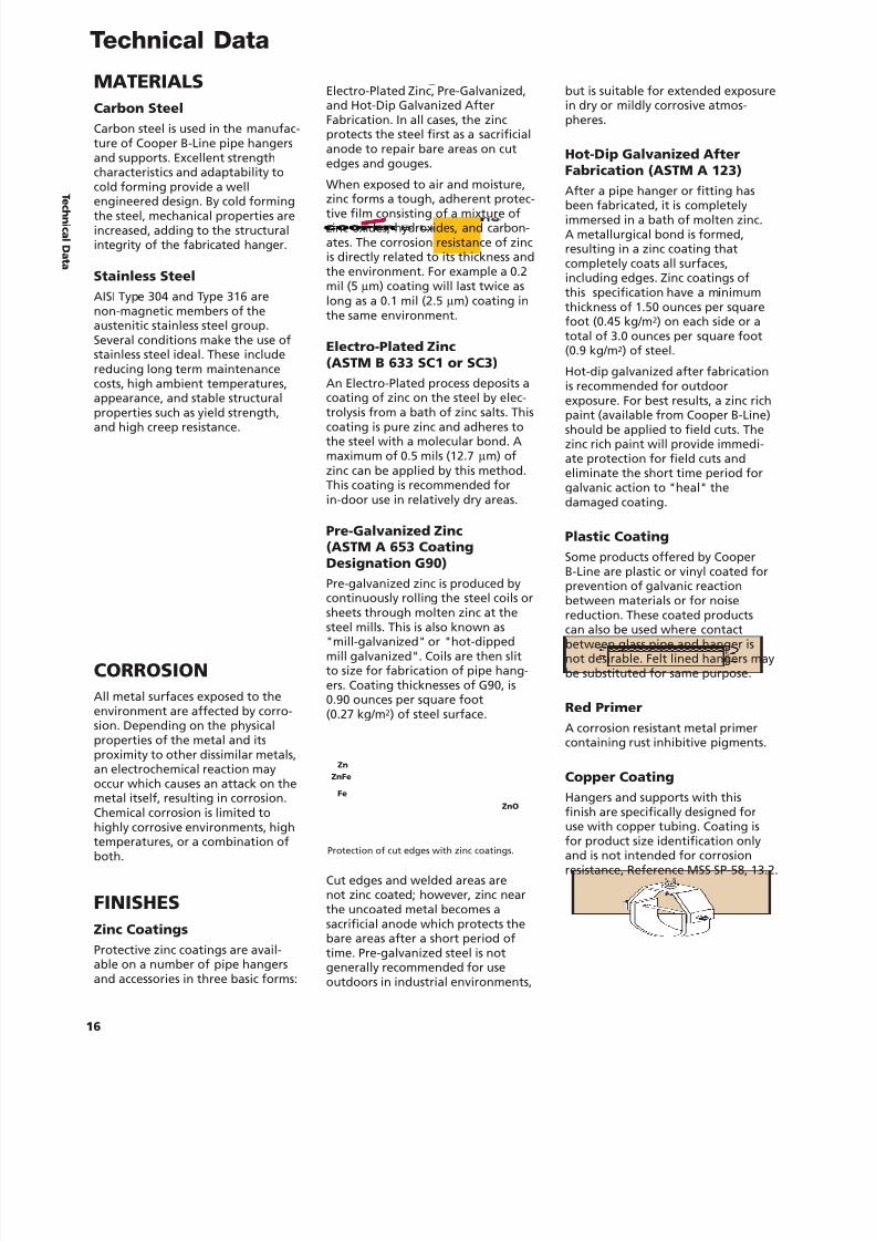
Electro-Plated Zinc, Pre-Galvanized,and Hot-Dip Galvanized AfterFabrication. In all cases, the zincprotects the steel first as a sacrificialanode to repair bare areas on cutedges and gouges.
When exposed to air and moisture,
zinc forms a tough, adherent protec-tive film consisting of a mixture ofzinc oxides, hydroxides, and carbon-ates. The corrosion resistance of zincis directly related to its thickness andthe environment. For example a 0.2mil (5 µ m) coating will last twice aslong as a 0.1 mil (2.5 µ m) coating inthe same environment.
Electro-Plated Zinc(ASTM B 633 SC1 or SC3)An Electro-Plated process deposits acoating of zinc on the steel by elec-trolysis from a bath of zinc salts. Thiscoating is pure zinc and adheres tothe steel with a molecular bond. Amaximum of 0.5 mils (12.7 µ m) ofzinc can be applied by this method.This coating is recommended forin-door use in relatively dry areas.
Pre-Galvanized Zinc(ASTM A 653 CoatingDesignation G90)Pre-galvanized zinc is produced bycontinuously rolling the steel coils or
sheets through molten zinc at thesteel mills. This is also known as"mill-galvanized" or "hot-dippedmill galvanized". Coils are then slitto size for fabrication of pipe hang-ers. Coating thicknesses of G90, is0.90 ounces per square foot(0.27 kg/m 2) of steel surface.
Cut edges and welded areas arenot zinc coated; however, zinc nearthe uncoated metal becomes asacrificial anode which protects thebare areas after a short period oftime. Pre-galvanized steel is notgenerally recommended for useoutdoors in industrial environments,
Protection of cut edges with zinc coatings.
Zn
Fe
ZnFe
ZnO
Technical Data
16
T ec h ni c al Dat a
7/18/2019 PH Pipe Hanger Catalog
http://slidepdf.com/reader/full/ph-pipe-hanger-catalog 19/224
7/18/2019 PH Pipe Hanger Catalog
http://slidepdf.com/reader/full/ph-pipe-hanger-catalog 20/224
7/18/2019 PH Pipe Hanger Catalog
http://slidepdf.com/reader/full/ph-pipe-hanger-catalog 21/224
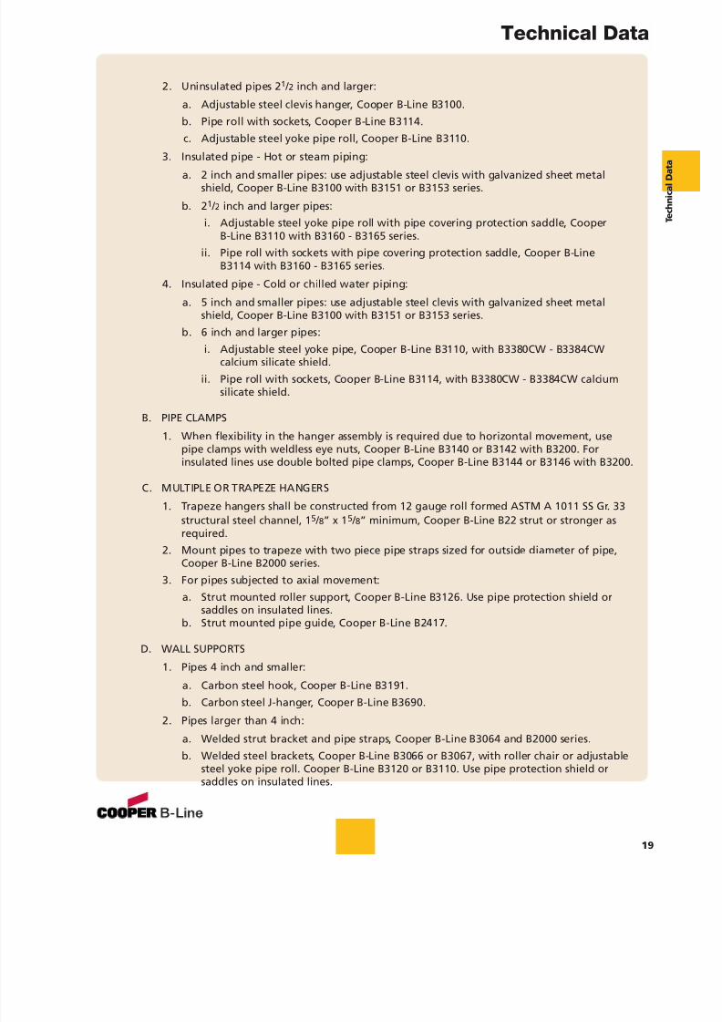
2. Uninsulated pipes 2 1 / 2 inch and larger:
a. Adjustable steel clevis hanger, Cooper B-Line B3100.b. Pipe roll with sockets, Cooper B-Line B3114.c. Adjustable steel yoke pipe roll, Cooper B-Line B3110.
3. Insulated pipe - Hot or steam piping:
a. 2 inch and smaller pipes: use adjustable steel clevis with galvanized sheet metalshield, Cooper B-Line B3100 with B3151 or B3153 series.
b. 2 1 / 2 inch and larger pipes:i. Adjustable steel yoke pipe roll with pipe covering protection saddle, Cooper
B-Line B3110 with B3160 - B3165 series.ii. Pipe roll with sockets with pipe covering protection saddle, Cooper B-Line
B3114 with B3160 - B3165 series.
4. Insulated pipe - Cold or chilled water piping:
a. 5 inch and smaller pipes: use adjustable steel clevis with galvanized sheet metalshield, Cooper B-Line B3100 with B3151 or B3153 series.
b. 6 inch and larger pipes:i. Adjustable steel yoke pipe, Cooper B-Line B3110, with B3380CW - B3384CWcalcium silicate shield.
ii. Pipe roll with sockets, Cooper B-Line B3114, with B3380CW - B3384CW calciumsilicate shield.
B. PIPE CLAMPS
1. When flexibility in the hanger assembly is required due to horizontal movement, usepipe clamps with weldless eye nuts, Cooper B-Line B3140 or B3142 with B3200. Forinsulated lines use double bolted pipe clamps, Cooper B-Line B3144 or B3146 with B3200.
C. MULTIPLE OR TRAPEZE HANGERS
1. Trapeze hangers shall be constructed from 12 gauge roll formed ASTM A 1011 SS Gr. 33structural steel channel, 1 5 / 8” x 1 5 / 8” minimum, Cooper B-Line B22 strut or stronger asrequired.
2. Mount pipes to trapeze with two piece pipe straps sized for outside diameter of pipe,Cooper B-Line B2000 series.
3. For pipes subjected to axial movement:a. Strut mounted roller support, Cooper B-Line B3126. Use pipe protection shield or
saddles on insulated lines.b. Strut mounted pipe guide, Cooper B-Line B2417.
D. WALL SUPPORTS
1. Pipes 4 inch and smaller:
a. Carbon steel hook, Cooper B-Line B3191.b. Carbon steel J-hanger, Cooper B-Line B3690.
2. Pipes larger than 4 inch:
a. Welded strut bracket and pipe straps, Cooper B-Line B3064 and B2000 series.b. Welded steel brackets, Cooper B-Line B3066 or B3067, with roller chair or adjustable
steel yoke pipe roll. Cooper B-Line B3120 or B3110. Use pipe protection shield orsaddles on insulated lines.
Technical Data
19
7/18/2019 PH Pipe Hanger Catalog
http://slidepdf.com/reader/full/ph-pipe-hanger-catalog 22/224
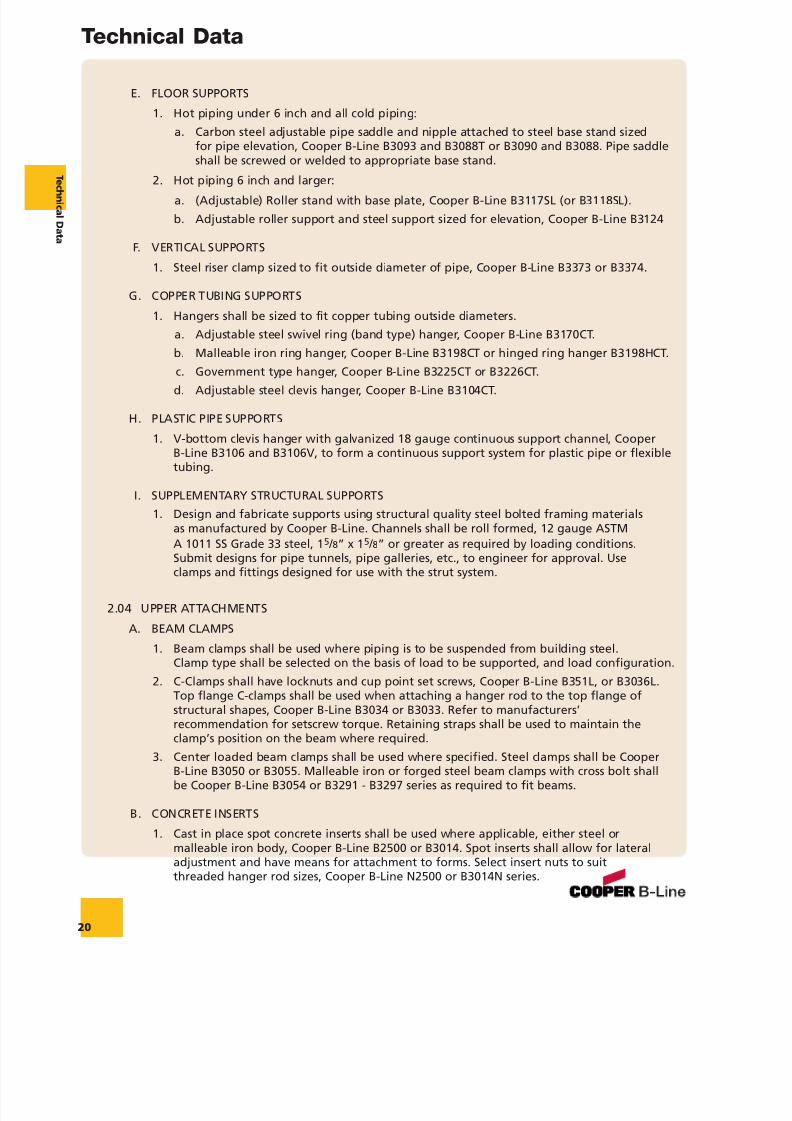
E. FLOOR SUPPORTS
1. Hot piping under 6 inch and all cold piping:a. Carbon steel adjustable pipe saddle and nipple attached to steel base stand sized
for pipe elevation, Cooper B-Line B3093 and B3088T or B3090 and B3088. Pipe saddleshall be screwed or welded to appropriate base stand.
2. Hot piping 6 inch and larger:a. (Adjustable) Roller stand with base plate, Cooper B-Line B3117SL (or B3118SL).b. Adjustable roller support and steel support sized for elevation, Cooper B-Line B3124
F. VERTICAL SUPPORTS
1. Steel riser clamp sized to fit outside diameter of pipe, Cooper B-Line B3373 or B3374.
G. COPPER TUBING SUPPORTS
1. Hangers shall be sized to fit copper tubing outside diameters.a. Adjustable steel swivel ring (band type) hanger, Cooper B-Line B3170CT.b. Malleable iron ring hanger, Cooper B-Line B3198CT or hinged ring hanger B3198HCT.
c. Government type hanger, Cooper B-Line B3225CT or B3226CT.d. Adjustable steel clevis hanger, Cooper B-Line B3104CT.
H. PLASTIC PIPE SUPPORTS
1. V-bottom clevis hanger with galvanized 18 gauge continuous support channel, CooperB-Line B3106 and B3106V, to form a continuous support system for plastic pipe or flexibletubing.
I. SUPPLEMENTARY STRUCTURAL SUPPORTS1. Design and fabricate supports using structural quality steel bolted framing materials
as manufactured by Cooper B-Line. Channels shall be roll formed, 12 gauge ASTMA 1011 SS Grade 33 steel, 1 5 / 8” x 1 5 / 8” or greater as required by loading conditions.Submit designs for pipe tunnels, pipe galleries, etc., to engineer for approval. Useclamps and fittings designed for use with the strut system.
2.04 UPPER ATTACHMENTS
A. BEAM CLAMPS
1. Beam clamps shall be used where piping is to be suspended from building steel.Clamp type shall be selected on the basis of load to be supported, and load configuration.
2. C-Clamps shall have locknuts and cup point set screws, Cooper B-Line B351L, or B3036L.Top flange C-clamps shall be used when attaching a hanger rod to the top flange ofstructural shapes, Cooper B-Line B3034 or B3033. Refer to manufacturers’recommendation for setscrew torque. Retaining straps shall be used to maintain the
clamp’s position on the beam where required.3. Center loaded beam clamps shall be used where specified. Steel clamps shall be Cooper
B-Line B3050 or B3055. Malleable iron or forged steel beam clamps with cross bolt shallbe Cooper B-Line B3054 or B3291 - B3297 series as required to fit beams.
B. CONCRETE INSERTS
1. Cast in place spot concrete inserts shall be used where applicable, either steel ormalleable iron body, Cooper B-Line B2500 or B3014. Spot inserts shall allow for lateraladjustment and have means for attachment to forms. Select insert nuts to suitthreaded hanger rod sizes, Cooper B-Line N2500 or B3014N series.
Technical Data
20
T ec h ni c al Dat a
7/18/2019 PH Pipe Hanger Catalog
http://slidepdf.com/reader/full/ph-pipe-hanger-catalog 23/224
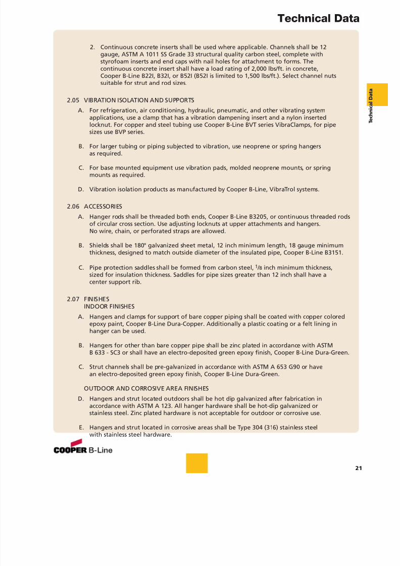
2. Continuous concrete inserts shall be used where applicable. Channels shall be 12gauge, ASTM A 1011 SS Grade 33 structural quality carbon steel, complete withstyrofoam inserts and end caps with nail holes for attachment to forms. Thecontinuous concrete insert shall have a load rating of 2,000 lbs/ft. in concrete,Cooper B-Line B22I, B32I, or B52I (B52I is limited to 1,500 lbs/ft.). Select channel nutssuitable for strut and rod sizes.
2.05 VIBRATION ISOLATION AND SUPPORTS
A. For refrigeration, air conditioning, hydraulic, pneumatic, and other vibrating systemapplications, use a clamp that has a vibration dampening insert and a nylon insertedlocknut. For copper and steel tubing use Cooper B-Line BVT series VibraClamps, for pipesizes use BVP series.
B. For larger tubing or piping subjected to vibration, use neoprene or spring hangersas required.
C. For base mounted equipment use vibration pads, molded neoprene mounts, or springmounts as required.
D. Vibration isolation products as manufactured by Cooper B-Line, VibraTrol systems.
2.06 ACCESSORIES
A. Hanger rods shall be threaded both ends, Cooper B-Line B3205, or continuous threaded rodsof circular cross section. Use adjusting locknuts at upper attachments and hangers.No wire, chain, or perforated straps are allowed.
B. Shields shall be 180° galvanized sheet metal, 12 inch minimum length, 18 gauge minimumthickness, designed to match outside diameter of the insulated pipe, Cooper B-Line B3151.
C. Pipe protection saddles shall be formed from carbon steel, 1 / 8 inch minimum thickness,sized for insulation thickness. Saddles for pipe sizes greater than 12 inch shall have acenter support rib.
2.07 FINISHESINDOOR FINISHES
A. Hangers and clamps for support of bare copper piping shall be coated with copper coloredepoxy paint, Cooper B-Line Dura-Copper. Additionally a plastic coating or a felt lining inhanger can be used.
B. Hangers for other than bare copper pipe shall be zinc plated in accordance with ASTMB 633 - SC3 or shall have an electro-deposited green epoxy finish, Cooper B-Line Dura-Green.
C. Strut channels shall be pre-galvanized in accordance with ASTM A 653 G90 or have
an electro-deposited green epoxy finish, Cooper B-Line Dura-Green.
OUTDOOR AND CORROSIVE AREA FINISHES
D. Hangers and strut located outdoors shall be hot dip galvanized after fabrication inaccordance with ASTM A 123. All hanger hardware shall be hot-dip galvanized orstainless steel. Zinc plated hardware is not acceptable for outdoor or corrosive use.
E. Hangers and strut located in corrosive areas shall be Type 304 (316) stainless steelwith stainless steel hardware.
Technical Data
21
7/18/2019 PH Pipe Hanger Catalog
http://slidepdf.com/reader/full/ph-pipe-hanger-catalog 24/224
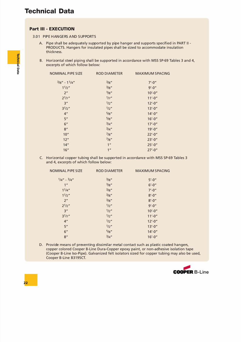
Part III - EXECUTION
3.01 PIPE HANGERS AND SUPPORTS
A. Pipe shall be adequately supported by pipe hanger and supports specified in PART II -PRODUCTS. Hangers for insulated pipes shall be sized to accommodate insulationthickness.
B. Horizontal steel piping shall be supported in accordance with MSS SP-69 Tables 3 and 4,excerpts of which follow below:
NOMINAL PIPE SIZE ROD DIAMETER MAXIMUM SPACING
3 / 8” - 1 1 / 4” 3 / 8” 7’-0”11 / 2” 3 / 8” 9’-0”
2” 3 / 8” 10’-0”21 / 2” 1 / 2” 11’-0”
3” 1 / 2” 12’-0”31 / 2” 1 / 2” 13’-0”
4” 5 / 8” 14’-0”5” 5 / 8” 16’-0”6” 3 / 4” 17’-0”8” 3 / 4” 19’-0”
10” 7 / 8” 22’-0”12” 7 / 8” 23’-0”14” 1” 25’-0”16” 1” 27’-0”
C. Horizontal copper tubing shall be supported in accordance with MSS SP-69 Tables 3and 4, excerpts of which follow below:
NOMINAL PIPE SIZE ROD DIAMETER MAXIMUM SPACING
1 / 4” - 3 / 4” 3 / 8” 5’-0”1” 3 / 8” 6’-0”
11 / 4” 3 / 8” 7’-0”11 / 2” 3 / 8” 8’-0”
2” 3 / 8” 8’-0”21 / 2” 1 / 2” 9’-0”
3” 1 / 2” 10’-0”31 / 2” 1 / 2” 11’-0”
4” 1 / 2” 12’-0”
5” 1 / 2” 13’-0”6” 5 / 8” 14’-0”8” 3 / 4” 16’-0”
D. Provide means of preventing dissimilar metal contact such as plastic coated hangers,copper colored Cooper B-Line Dura-Copper epoxy paint, or non-adhesive isolation tape(Cooper B-Line Iso-Pipe). Galvanized felt isolators sized for copper tubing may also be used,Cooper B-Line B3195CT.
Technical Data
22
T ec h ni c al Dat a
7/18/2019 PH Pipe Hanger Catalog
http://slidepdf.com/reader/full/ph-pipe-hanger-catalog 25/224
E. Support horizontal cast iron pipe adjacent to each hub, with 10 feet maximum spacingbetween hangers.
F. Install hangers to provide a minimum of 1 / 2 inch space between finished covering andadjacent work.
G. Place a hanger within 12 inches of each horizontal elbow.
H. Support vertical piping independently of connected horizontal piping. Support verticalpipes at every (other) floor. Wherever possible, locate riser clamps directly below pipecouplings or shear lugs.
I. Where several pipes can be installed in parallel and at the same elevation, provide trapezehangers as specified in Section 2.02 C. Trapeze hangers shall be spaced according to thesmallest pipe size, or install intermediate supports according to schedule in Section 3.01 B.
J. Do not support piping from other pipes, ductwork or other equipment which is notbuilding structure.
3.02 CONCRETE INSERTSA. Provide inserts for placement in formwork before concrete is poured.
B. Provide inserts for suspending hangers from reinforced concrete slabs and sides ofreinforced concrete beams.
C. Where concrete slabs form finished ceilings, provide inserts to be flush with slab surface.
D. Provide hooked rod to concrete reinforcement section for inserts carrying pipe over 4 inch.
Technical Data
23
7/18/2019 PH Pipe Hanger Catalog
http://slidepdf.com/reader/full/ph-pipe-hanger-catalog 26/224
7/18/2019 PH Pipe Hanger Catalog
http://slidepdf.com/reader/full/ph-pipe-hanger-catalog 27/224
7/18/2019 PH Pipe Hanger Catalog
http://slidepdf.com/reader/full/ph-pipe-hanger-catalog 28/224
7/18/2019 PH Pipe Hanger Catalog
http://slidepdf.com/reader/full/ph-pipe-hanger-catalog 29/224
7/18/2019 PH Pipe Hanger Catalog
http://slidepdf.com/reader/full/ph-pipe-hanger-catalog 30/224
7/18/2019 PH Pipe Hanger Catalog
http://slidepdf.com/reader/full/ph-pipe-hanger-catalog 31/224
7/18/2019 PH Pipe Hanger Catalog
http://slidepdf.com/reader/full/ph-pipe-hanger-catalog 32/224
7/18/2019 PH Pipe Hanger Catalog
http://slidepdf.com/reader/full/ph-pipe-hanger-catalog 33/224

7/18/2019 PH Pipe Hanger Catalog
http://slidepdf.com/reader/full/ph-pipe-hanger-catalog 34/224
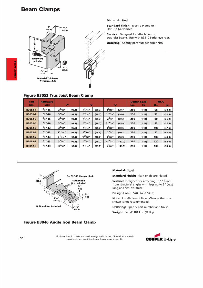
Beam Clamps
32All dimensions in charts and on drawings are in inches. Dimensions shown in
parentheses are in millimeters unless otherwise specified.
Material: Steel
Standard Finish: Plain or Electro-Plated
Service: Designed for attaching hanger rodscentered under beam flanges. Recommendedto use with B3200 Series up to size 1 1 / 2" (38.1) .
Ordering: Specify part number, flange width,and finish.
Approvals: Complies with FederalSpecification WW-H-171E & A-A-1192A Type 21and Manufacturers Standardization SocietyMSS SP-69 & SP-58 Type 21.
Part NumberExample: B3050-2 x 'W' finish
Figure B3050 Beam Clamp
Bolt and Nut Included'B'
'W'
'C'
'A'
Steel Size
Bolt Size
'A'Center of bolt to bottom
of beam flange.
Part No. Bolt 'B' Design Load& Size Size 'A' Minimum 'C' Steel Size Lbs. kN
B3050-2 1 / 2"-13 1 3 / 8" (34.9) 5 / 8" (15.9) 21 / 8" (54.0) 1 / 4"x 1 1 / 4" (6.3 x 31.7) 1000 (3.11)
B3050-5 3 / 4"-10 1 7 / 8" (47.6) 7 / 8" (22.2) 3" (76.2) 1 / 2"x2" (12.7x 50.8) 3000 (6.67)
B3050-7 1 1 / 8"-7 2 1 / 2" (63.5) 11 / 8" (28.6) 41 / 4" (108.0) 5 / 8"x4" (15.9x 101.6) 5000 (22.24)
Flange Width Flange Thickness Wt./C For Beam Clamp Size Lbs. (kg)'W' Min. Max. 2 5 7
3" (76.2) 1 / 4" (6.3) 3 / 8" (9.5) 103 (46.7) -- -- -- --
4" (101.6) 3 / 16 " (4.8) 1 / 2" (12.7) 116 (52.6) 429 (194.6) -- --
5" (127.0) 5 / 16 " (7.9) 5 / 8" (15.9) 125 (56.7) 458 (207.8) 1419 (643.7)
6" (152.4) 1 / 4" (6.3) 3 / 4" (19.0) 134 (60.8) 486 (220.5) 1490 (675.9)
7" (177.8) 7 / 16 " (11.1) 7 / 8" (22.2) 143 (64.9) 514 (233.2) 1561 (708.1)
8" (203.2) 7 / 16 " (11.1) 7 / 8" (22.2) 152 (69.0) 543 (246.3) 1632 (740.3)
9" (228.6) 9 / 16 " (14.3) 1" (25.4) 160 (72.6) 571 (259.0) 1702 (772.0)
10" (254.0) 5 / 8" (15.9) 1" (25.4) 169 (76.7) 599 (271.8) 1773 (804.2)
12" (304.8) 5 / 8" (15.9) 11 / 4" (31.7) 187 (84.8) 656 (297.6) 1915 (868.6)
B eam C l amps
7/18/2019 PH Pipe Hanger Catalog
http://slidepdf.com/reader/full/ph-pipe-hanger-catalog 35/224
7/18/2019 PH Pipe Hanger Catalog
http://slidepdf.com/reader/full/ph-pipe-hanger-catalog 36/224
Beam Clamps
34All dimensions in charts and on drawings are in inches. Dimensions shown in
parentheses are in millimeters unless otherwise specified.
To determine (mm) in the above chart, multiply inches by 25.4.* Rod Size required to finish part number (see Rod Size 'A' in top chart).∆ These part numbers are furnished with links.
Without Links
'C'
'E'
'B'
'A'
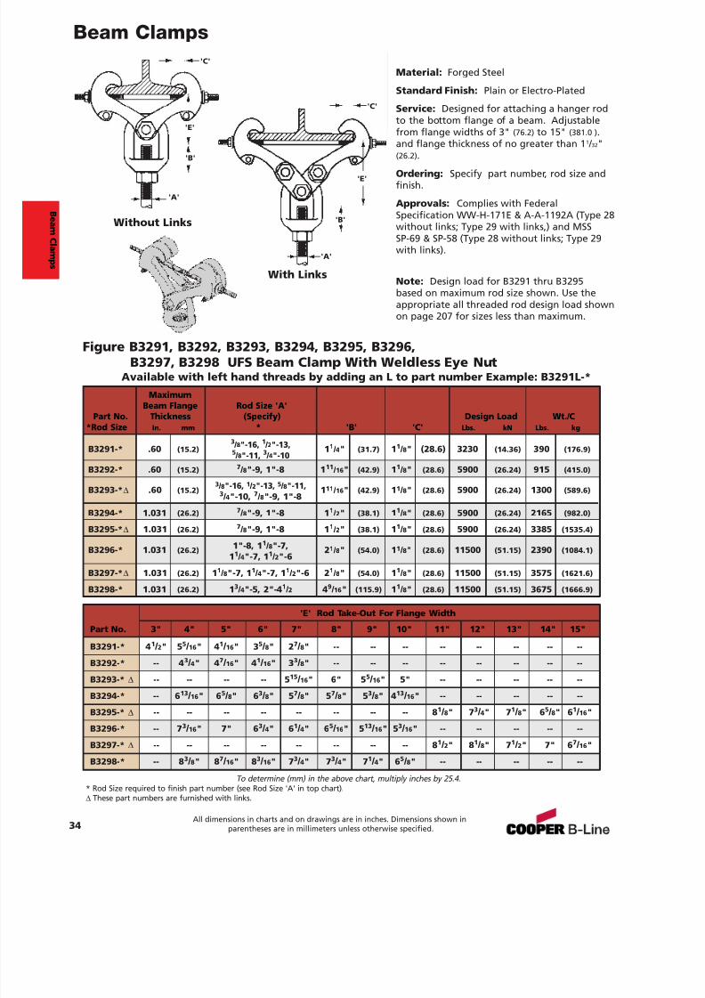
Figure B3291, B3292, B3293, B3294, B3295, B3296,B3297, B3298 UFS Beam Clamp With Weldless Eye Nut
Available with left hand threads by adding an L to part number Example: B3291L-*Maximum
Beam Flange Rod Size 'A'Part No. Thickness (Specify) Design Load Wt./C
*Rod Size In. mm * 'B' 'C' Lbs. kN Lbs. kg
B3291-* .60 (15.2)3 / 8"-16, 1 / 2"-13, 1 1 / 4" (31.7) 1 1 / 8" (28.6) 3230 (14.36) 390 (176.9)5 / 8"-11, 3 / 4"-10
B3292-* .60 (15.2) 7 / 8"-9, 1"-8 1 11 / 16 " (42.9) 1 1 / 8" (28.6) 5900 (26.24) 915 (415.0)
B3293-* ∆ .60 (15.2)3 / 8"-16, 1 / 2"-13, 5 / 8"-11, 1 11 / 16 " (42.9) 1 1 / 8" (28.6) 5900 (26.24) 1300 (589.6)
3 / 4"-10, 7 / 8"-9, 1"-8
B3294-* 1.031 (26.2) 7 / 8"-9, 1"-8 1 1 / 2" (38.1) 1 1 / 8" (28.6) 5900 (26.24) 2165 (982.0)
B3295-* ∆ 1.031 (26.2) 7 / 8"-9, 1"-8 1 1 / 2" (38.1) 1 1 / 8" (28.6) 5900 (26.24) 3385 (1535.4)
B3296-* 1.031 (26.2) 1"-8, 1 1 / 8"-7, 2 1 / 8" (54.0) 1 1 / 8" (28.6) 11500 (51.15) 2390 (1084.1)1 1 / 4"-7, 1 1 / 2"-6
B3297-* ∆ 1.031 (26.2) 1 1 / 8"-7, 1 1 / 4"-7, 1 1 / 2"-6 2 1 / 8" (54.0) 1 1 / 8" (28.6) 11500 (51.15) 3575 (1621.6)
B3298-* 1.031 (26.2) 1 3 / 4"-5, 2"-4 1 / 2 4 9 / 16 " (115.9) 1 1 / 8" (28.6) 11500 (51.15) 3675 (1666.9)
'E' Rod Take-Out For Flange Width
Part No. 3" 4" 5" 6" 7" 8" 9" 10" 11" 12" 13" 14" 15"
B3291-* 4 1 / 2" 5 5 / 16 " 4 1 / 16 " 3 5 / 8" 2 7 / 8" -- -- -- -- -- -- -- --
B3292-* -- 4 3 / 4" 4 7 / 16 " 4 1 / 16 " 3 3 / 8" -- -- -- -- -- -- -- --
B3293-* ∆ -- -- -- -- 5 15 / 16 " 6" 5 5 / 16 " 5" -- -- -- -- --
B3294-* -- 6 13 / 16 " 6 5 / 8" 6 3 / 8" 5 7 / 8" 5 7 / 8" 5 3 / 8" 4 13 / 16 " -- -- -- -- --
B3295-* ∆ -- -- -- -- -- -- -- -- 8 1 / 8" 7 3 / 4" 7 1 / 8" 6 5 / 8" 6 1 / 16 "
B3296-* -- 7 3 / 16 " 7" 6 3 / 4" 6 1 / 4" 6 5 / 16 " 5 13 / 16 " 5 3 / 16 " -- -- -- -- --
B3297-* ∆ -- -- -- -- -- -- -- -- 8 1 / 2" 8 1 / 8" 7 1 / 2" 7" 6 7 / 16 "
B3298-* -- 8 3 / 8" 8 7 / 16 " 8 3 / 16 " 7 3 / 4" 7 3 / 4" 7 1 / 4" 6 5 / 8" -- -- -- -- --
With Links
'C'
'E'
'B'
'A'
Material: Forged Steel
Standard Finish: Plain or Electro-Plated
Service: Designed for attaching a hanger rodto the bottom flange of a beam. Adjustablefrom flange widths of 3" (76.2) to 15" (381.0 ) .and flange thickness of no greater than 1 1 / 32"(26.2) .
Ordering: Specify part number, rod size andfinish.
Approvals: Complies with FederalSpecification WW-H-171E & A-A-1192A (Type 28without links; Type 29 with links,) and MSSSP-69 & SP-58 (Type 28 without links; Type 29with links).
Note: Design load for B3291 thru B3295based on maximum rod size shown. Use theappropriate all threaded rod design load shownon page 207 for sizes less than maximum.
B eam C l amps
7/18/2019 PH Pipe Hanger Catalog
http://slidepdf.com/reader/full/ph-pipe-hanger-catalog 37/224
7/18/2019 PH Pipe Hanger Catalog
http://slidepdf.com/reader/full/ph-pipe-hanger-catalog 38/224
Beam Clamps
36All dimensions in charts and on drawings are in inches. Dimensions shown in
parentheses are in millimeters unless otherwise specified.
Material: Steel
Standard Finish: Plain or Electro-Plated
Service: Designed for attaching 1 / 2"-13 rodfrom structural angles with legs up to 3" (76.2)long and 3 / 8" (9.5) thick.
Design Load: 570 Lbs. (2.54 kN)
Note: Installation of Beam Clamp other thanshown is not recommended.
Ordering: Specify part number and finish.
Weight: Wt./C 181 Lbs. (82.1kg)
Figure B3046 Angle Iron Beam Clamp
Bolt and Nut Included
For 1 / 2"-13 Hanger Rod.
Hanger RodNot Included
3 / 8"(9.5)
3 / 8"(9.5)
11 / 2"(38.1)
65 / 8"(168.3)
2"(50.8)
Material: Steel
Standard Finish: Electro-Plated orHot-Dip Galvanized
Service: Designed for attachment totrus joist beams. Use with B3210 Series eye rods.
Ordering: Specify part number and finish.
Figure B3052 Trus Joist Beam Clamp
HardwareIncluded
3 / 4"(19.0)3 / 8"
(9.5)
1 / 2"(12.7)
2"(50.8)
‘C’
‘B’
‘A’
Material Thickness11 Gauge (3.0)
Part Hardware Design Load Wt./CNo. Size ‘A’ 'B' 'C' Lbs. kN Lbs. kg
B3052-1 3 / 8”-16 3 9 / 16 " (92.1) 1 9 / 16 " (39.7) 1 9 / 16 " (39.7) 250 (1.11) 68 (30.8)
B3052-2 3 / 8”-16 3 9 / 16 " (92.1) 1 9 / 16 " (39.7) 1 13 / 16 " (46.0) 250 (1.11) 72 (32.6)
B3052-3 3 / 8”-16 3 9 / 16 " (92.1) 1 9 / 16 " (39.7) 2 3 / 8" (60.3) 250 (1.11) 80 (36.3)
B3052-4 3 / 8”-16 3 9 / 16 " (92.1) 1 9 / 16 " (39.7) 2 19 / 32 " (65.9) 250 (1.11) 83 (37.6)
B3052-5 1 / 2”-13 3 9 / 16 " (96.8) 1 9 / 16 " (39.7) 3 9 / 16 " (90.5) 250 (1.11) 105 (47.6)
B3052-6 1 / 2”-13 3 13 / 16 " (96.8) 1 13 / 16 " (46.0) 2 3 / 8" (60.3) 250 (1.11) 92 (41.7)
B3052-7 1 / 2”-13 3 13 / 16 " (92.1) 1 13 / 16 " (46.0) 3 9 / 16 " (90.5) 250 (1.11) 108 (49.0)
B3052-8 1 / 2”-13 3 9 / 16 " (92.1) 1 9 / 16 " (39.7) 4 13 / 16 " (122.2) 250 (1.11) 120 (54.4)
B3052-9 1 / 2”-13 3 9 / 16 " (92.1) 1 9 / 16 " (39.7) 5 9 / 16 " (141.3) 250 (1.11) 130 (58.9)
B eam C l amps
7/18/2019 PH Pipe Hanger Catalog
http://slidepdf.com/reader/full/ph-pipe-hanger-catalog 39/224
Beam Clamps
37All dimensions in charts and on drawings are in inches. Dimensions shown in
parentheses are in millimeters unless otherwise specified.
7/18/2019 PH Pipe Hanger Catalog
http://slidepdf.com/reader/full/ph-pipe-hanger-catalog 40/224
P i peHanger s
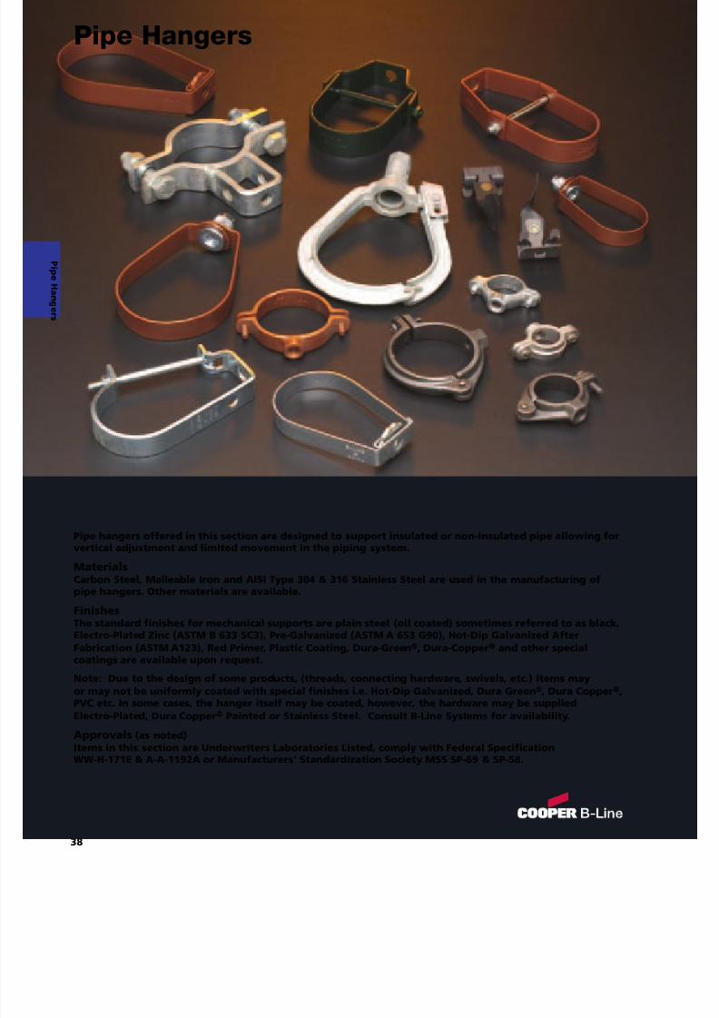
Pipe hangers offered in this section are designed to support insulated or non-insulated pipe allowing forvertical adjustment and limited movement in the piping system.
MaterialsCarbon Steel, Malleable Iron and AISI Type 304 & 316 Stainless Steel are used in the manufacturing ofpipe hangers. Other materials are available.
FinishesThe standard finishes for mechanical supports are plain steel (oil coated) sometimes referred to as black,Electro-Plated Zinc (ASTM B 633 SC3), Pre-Galvanized (ASTM A 653 G90), Hot-Dip Galvanized AfterFabrication (ASTM A123), Red Primer, Plastic Coating, Dura-Green ®, Dura-Copper ® and other specialcoatings are available upon request.
Note: Due to the design of some products, (threads, connecting hardware, swivels, etc.) items mayor may not be uniformly coated with special finishes i.e. Hot-Dip Galvanized, Dura Green ®, Dura Copper ®,PVC etc. In some cases, the hanger itself may be coated, however, the hardware may be suppliedElectro-Plated, Dura Copper ® Painted or Stainless Steel. Consult B-Line Systems for availability.
Approvals (as noted)Items in this section are Underwriters Laboratories Listed, comply with Federal SpecificationWW-H-171E & A-A-1192A or Manufacturers' Standardization Society MSS SP-69 & SP-58.
38
Pipe Hangers
7/18/2019 PH Pipe Hanger Catalog
http://slidepdf.com/reader/full/ph-pipe-hanger-catalog 41/224
7/18/2019 PH Pipe Hanger Catalog
http://slidepdf.com/reader/full/ph-pipe-hanger-catalog 42/224
7/18/2019 PH Pipe Hanger Catalog
http://slidepdf.com/reader/full/ph-pipe-hanger-catalog 43/224
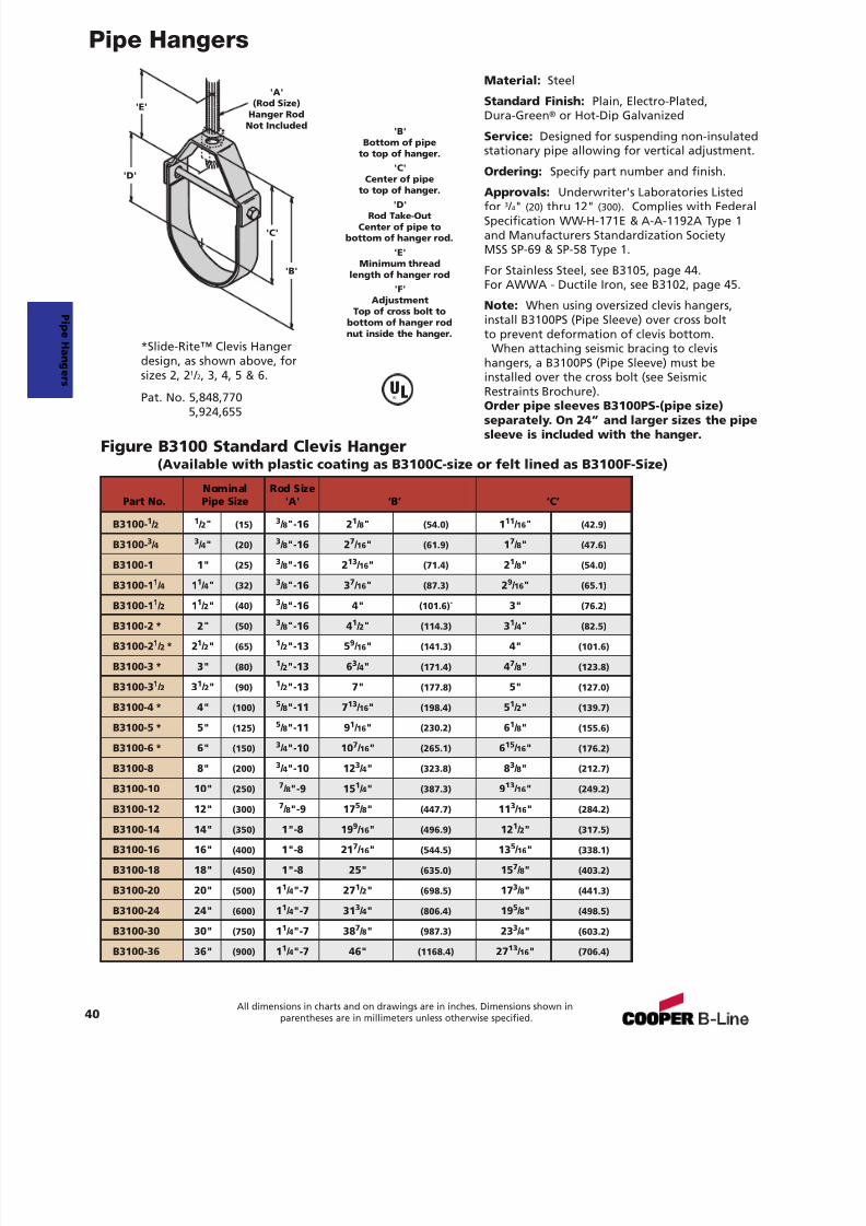
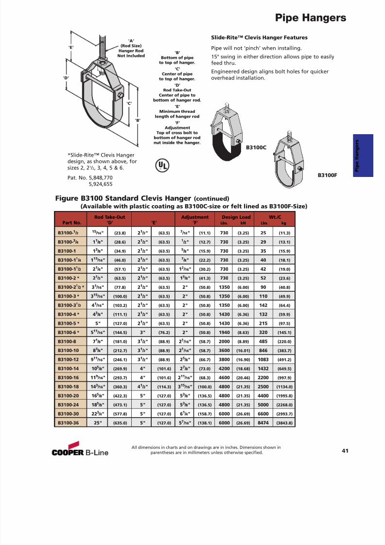
Pipe Hangers
Figure B3100 Standard Clevis Hanger (continued)(Available with plastic coating as B3100C-size or felt lined as B3100F-Size)
'B'Bottom of pipe
to top of hanger.'C'
Center of pipeto top of hanger.
'D'
Rod Take-OutCenter of pipe to
bottom of hanger rod.'E'
Minimum threadlength of hanger rod
'F'Adjustment
Top of cross bolt tobottom of hanger rodnut inside the hanger.
Rod Take-Out Adjustment Design Load Wt./CPart No. 'D' 'E' 'F' Lbs. kN Lbs. kg
B3100- 1 / 2 15 / 16 " (23.8) 21 / 2" (63.5) 7 / 16 " (11.1) 730 (3.25) 25 (11.3)
B3100- 3 / 4 11 / 8" (28.6) 21 / 2" (63.5) 1 / 2" (12.7) 730 (3.25) 29 (13.1)
B3100-1 1 3 / 8" (34.9) 21 / 2" (63.5) 5 / 8" (15.9) 730 (3.25) 35 (15.9)
B3100-1 1 / 4 113 / 16 " (46.0) 21 / 2" (63.5) 7 / 8" (22.2) 730 (3.25) 40 (18.1)
B3100-11 / 2 2
1 / 4" (57.1) 2
1 / 2" (63.5) 1
3 / 16" (30.2) 730 (3.25) 42 (19.0)
B3100-2 * 2 1 / 2" (63.5) 21 / 2" (63.5) 15 / 8" (41.3) 730 (3.25) 52 (23.6)
B3100-2 1 / 2 * 3 1 / 16 " (77.8) 21 / 2" (63.5) 2" (50.8) 1350 (6.00) 90 (40.8)
B3100-3 * 3 15 / 16 " (100.0) 21 / 2" (63.5) 2" (50.8) 1350 (6.00) 110 (49.9)
B3100-3 1 / 2 41 / 16 " (103.2) 21 / 2" (63.5) 2" (50.8) 1350 (6.00) 142 (64.4)
B3100-4 * 4 3 / 8" (111.1) 21 / 2" (63.5) 2" (50.8) 1430 (6.36) 132 (59.9)
B3100-5 * 5" (127.0) 21 / 2" (63.5) 2" (50.8) 1430 (6.36) 215 (97.5)
B3100-6 * 5 11 / 16 " (144.5) 3" (76.2) 2" (50.8) 1940 (8.63) 320 (145.1)
B3100-8 7 1 / 8" (181.0) 31 / 2" (88.9) 25 / 16" (58.7) 2000 (8.89) 485 (220.0)
B3100-10 8 3 / 8" (212.7) 31 / 2" (88.9) 25 / 16" (58.7) 3600 (16.01) 846 (383.7)
B3100-12 911
/ 16 " (246.1) 31 / 2" (88.9) 2
5 / 8" (66.7) 3800 (16.90) 1083 (491.2)
B3100-14 10 5 / 8" (269.9) 4" (101.6) 27 / 8" (73.0) 4200 (18.68) 1432 (649.5)
B3100-16 11 9 / 16 " (293.7) 4" (101.6) 211 / 16 " (68.3) 4600 (20.46) 2200 (997.9)
B3100-18 14 3 / 16 " (360.3) 41 / 2" (114.3) 315 / 16 " (100.0) 4800 (21.35) 2500 (1134.0)
B3100-20 16 5 / 8" (422.3) 5" (127.0) 53 / 8" (136.5) 4800 (21.35) 4400 (1995.8)
B3100-24 18 5 / 8" (473.1) 5" (127.0) 53 / 8" (136.5) 4800 (21.35) 5000 (2268.0)
B3100-30 22 3 / 4" (577.8) 5" (127.0) 61 / 4" (158.7) 6000 (26.69) 6600 (2993.7)
B3100-36 25" (635.0) 5" (127.0) 57 / 16" (138.1) 6000 (26.69) 8474 (3843.8)
'B'
'D'
'C'
'E'
'A'(Rod Size)
Hanger RodNot Included
*Slide-Rite™ Clevis Hangerdesign, as shown above, forsizes 2, 2 1 / 2, 3, 4, 5 & 6.
Pat. No. 5,848,7705,924,655
B3100C
B3100F
Slide-Rite™ Clevis Hanger Features
Pipe will not ‘pinch’ when installing.
15° swing in either direction allows pipe to easilyfeed thru.
Engineered design aligns bolt holes for quickeroverhead installation.
41All dimensions in charts and on drawings are in inches. Dimensions shown in
parentheses are in millimeters unless otherwise specified.
UL®
7/18/2019 PH Pipe Hanger Catalog
http://slidepdf.com/reader/full/ph-pipe-hanger-catalog 44/224
7/18/2019 PH Pipe Hanger Catalog
http://slidepdf.com/reader/full/ph-pipe-hanger-catalog 45/224
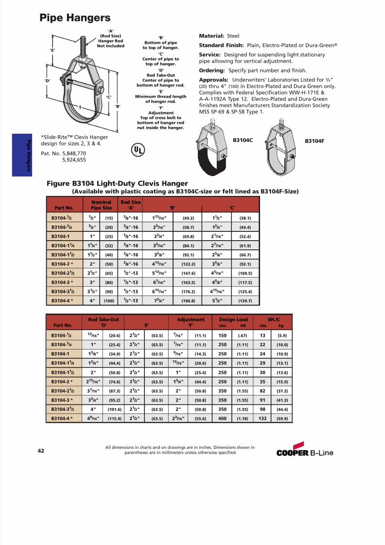
Pipe Hangers
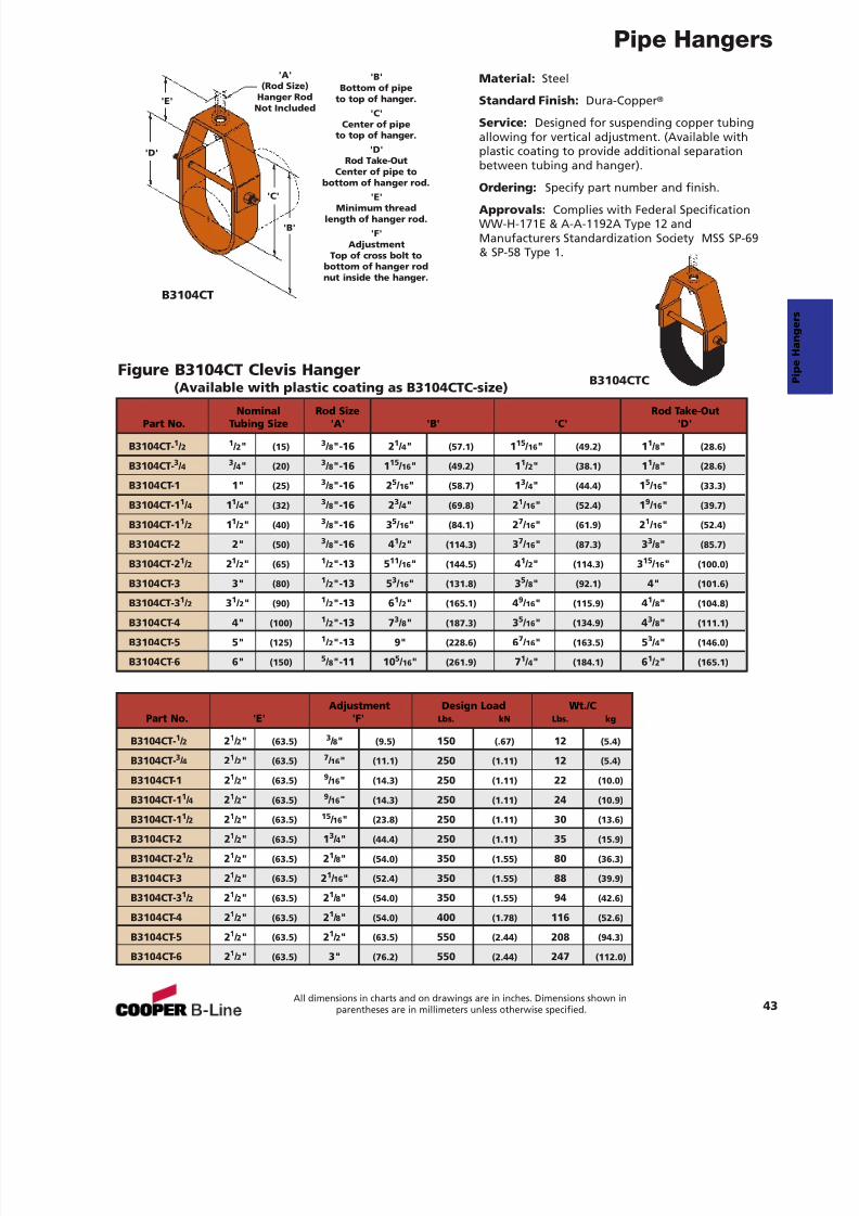
Figure B3104CT Clevis Hanger(Available with plastic coating as B3104CTC-size)
Material: Steel
Standard Finish: Dura-Copper ®
Service: Designed for suspending copper tubingallowing for vertical adjustment. (Available withplastic coating to provide additional separationbetween tubing and hanger).
Ordering: Specify part number and finish.
Approvals: Complies with Federal SpecificationWW-H-171E & A-A-1192A Type 12 andManufacturers Standardization Society MSS SP-69& SP-58 Type 1.
B3104CT
B3104CTC
'A'(Rod Size)
Hanger RodNot Included
'B'
'D'
'C'
'E'
'B'Bottom of pipe
to top of hanger.'C'
Center of pipeto top of hanger.
'D'Rod Take-Out
Center of pipe tobottom of hanger rod.
'E'Minimum threadlength of hanger rod.
'F'Adjustment
Top of cross bolt tobottom of hanger rodnut inside the hanger.
Nominal Rod Size Rod Take-OutPart No. Tubing Size 'A' 'B' 'C' 'D'
B3104CT- 1 / 2 1 / 2" (15) 3 / 8"-16 2 1 / 4" (57.1) 115 / 16 " (49.2) 11 / 8" (28.6)
B3104CT- 3 / 4 3 / 4" (20) 3 / 8"-16 1 15 / 16 " (49.2) 11 / 2" (38.1) 11 / 8" (28.6)
B3104CT-1 1" (25) 3 / 8"-16 2 5 / 16" (58.7) 13 / 4" (44.4) 15 / 16 " (33.3)
B3104CT-1 1 / 4 11 / 4" (32) 3 / 8"-16 2 3 / 4" (69.8) 21 / 16 " (52.4) 19 / 16 " (39.7)
B3104CT-1 1 / 2 11 / 2" (40) 3 / 8"-16 3 5 / 16" (84.1) 27 / 16 " (61.9) 21 / 16 " (52.4)
B3104CT-2 2" (50) 3 / 8"-16 4 1 / 2" (114.3) 37 / 16 " (87.3) 33 / 8" (85.7)
B3104CT-2 1 / 2 21 / 2" (65) 1 / 2"-13 5 11 / 16 " (144.5) 41 / 2" (114.3) 315 / 16 " (100.0)
B3104CT-3 3" (80) 1 / 2"-13 5 3 / 16" (131.8) 35 / 8" (92.1) 4" (101.6)
B3104CT-3 1 / 2 31 / 2" (90) 1 / 2"-13 6 1 / 2" (165.1) 49 / 16 " (115.9) 41 / 8" (104.8)
B3104CT-4 4" (100) 1 / 2"-13 7 3 / 8" (187.3) 35 / 16 " (134.9) 43 / 8" (111.1)
B3104CT-5 5" (125) 1 / 2"-13 9" (228.6) 67 / 16 " (163.5) 53 / 4" (146.0)
B3104CT-6 6" (150) 5 / 8"-11 10 5 / 16" (261.9) 71 / 4" (184.1) 61 / 2" (165.1)
Adjustment Design Load Wt./CPart No. 'E' 'F' Lbs. kN Lbs. kg
B3104CT- 1 / 2 21 / 2" (63.5) 3 / 8" (9.5) 150 (.67) 12 (5.4)
B3104CT- 3 / 4 21 / 2" (63.5) 7 / 16 " (11.1) 250 (1.11) 12 (5.4)
B3104CT-1 2 1 / 2" (63.5) 9 / 16 " (14.3) 250 (1.11) 22 (10.0)
B3104CT-11
/ 4 21
/ 2" (63.5)9
/ 16 " (14.3) 250 (1.11) 24 (10.9)B3104CT-1 1 / 2 21 / 2" (63.5) 15 / 16 " (23.8) 250 (1.11) 30 (13.6)
B3104CT-2 2 1 / 2" (63.5) 13 / 4" (44.4) 250 (1.11) 35 (15.9)
B3104CT-2 1 / 2 21 / 2" (63.5) 21 / 8" (54.0) 350 (1.55) 80 (36.3)
B3104CT-3 2 1 / 2" (63.5) 21 / 16 " (52.4) 350 (1.55) 88 (39.9)
B3104CT-3 1 / 2 21 / 2" (63.5) 21 / 8" (54.0) 350 (1.55) 94 (42.6)
B3104CT-4 2 1 / 2" (63.5) 21 / 8" (54.0) 400 (1.78) 116 (52.6)
B3104CT-5 2 1 / 2" (63.5) 21 / 2" (63.5) 550 (2.44) 208 (94.3)
B3104CT-6 2 1 / 2" (63.5) 3" (76.2) 550 (2.44) 247 (112.0)
43All dimensions in charts and on drawings are in inches. Dimensions shown in
parentheses are in millimeters unless otherwise specified.
7/18/2019 PH Pipe Hanger Catalog
http://slidepdf.com/reader/full/ph-pipe-hanger-catalog 46/224
Pipe Hangers
44All dimensions in charts and on drawings are in inches. Dimensions shown in
parentheses are in millimeters unless otherwise specified.
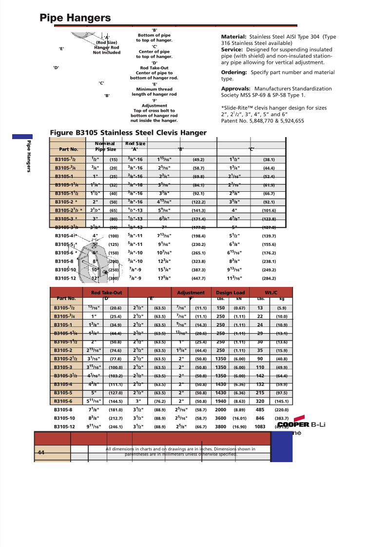
Material: Stainless Steel AISI Type 304 (Type316 Stainless Steel available)Service: Designed for suspending insulatedpipe (with shield) and non-insulated station-ary pipe allowing for vertical adjustment.
Ordering: Specify part number and materialtype.
Approvals: Manufacturers StandardizationSociety MSS SP-69 & SP-58 Type 1.
*Slide-Rite™ clevis hanger design for sizes2”, 2 1 / 2”, 3”, 4”, 5” and 6”Patent No. 5,848,770 & 5,924,655
Figure B3105 Stainless Steel Clevis Hanger
'B'
'D'
'C'
'E'
'A'(Rod Size)
Hanger RodNot Included
'B'Bottom of pipe
to top of hanger.'C'
Center of pipeto top of hanger.
'D'Rod Take-Out
Center of pipe tobottom of hanger rod.
'E'
Minimum threadlength of hanger rod'F'
AdjustmentTop of cross bolt to
bottom of hanger rodnut inside the hanger.
Rod Take-Out Adjustment Design Load Wt./CPart No. 'D' 'E' 'F' Lbs. kN Lbs. kg
B3105- 1 / 2 13 / 16 " (20.6) 21 / 2" (63.5) 7 / 16 " (11.1) 150 (0.67) 13 (5.9)
B3105- 3 / 4 1" (25.4) 21 / 2" (63.5) 7 / 16 " (11.1) 250 (1.11) 22 (10.0)
B3105-1 1 3 / 8" (34.9) 21 / 2" (63.5) 9 / 16 " (14.3) 250 (1.11) 24 (10.9)
B3105-1 1 / 4 13 / 4" (44.4) 21 / 2" (63.5) 13 / 16 " (20.6) 250 (1.11) 29 (13.1)
B3105-1 1 / 2 2" (50.8) 21 / 2" (63.5) 1" (25.4) 250 (1.11) 30 (13.6)
B3105-2 2 15 / 16 " (74.6) 21 / 2" (63.5) 13 / 4" (44.4) 250 (1.11) 35 (15.9)
B3105-2 1 / 2 31 / 16 " (77.8) 21 / 2" (63.5) 2" (50.8) 1350 (6.00) 90 (40.8)
B3105-3 3 15 / 16 " (100.0) 21 / 2" (63.5) 2" (50.8) 1350 (6.00) 110 (49.9)
B3105-3 1 / 2 41 / 16 " (103.2) 21 / 2" (63.5) 2" (50.8) 1350 (6.00) 142 (64.4)
B3105-4 4 3 / 8" (111.1) 21 / 2" (63.5) 2" (50.8) 1430 (6.36) 132 (59.9)
B3105-5 5" (127.0) 21 / 2" (63.5) 2" (50.8) 1430 (6.36) 215 (97.5)
B3105-6 5 11 / 16 " (144.5) 3" (76.2) 2" (50.8) 1940 (8.63) 320 (145.1)
B3105-8 7 1 / 8" (181.0) 31 / 2" (88.9) 25 / 16 " (58.7) 2000 (8.89) 485 (220.0)
B3105-10 8 3 / 8" (212.7) 31 / 2" (88.9) 25 / 16 " (58.7) 3600 (16.01) 846 (383.7)
B3105-12 9 11 / 16 " (246.1) 31 / 2" (88.9) 25 / 8" (66.7) 3800 (16.90) 1083 (491.2)
Nominal Rod SizePart No. Pipe Size 'A' 'B' ‘C’
B3105- 1 / 2 1 / 2" (15) 3 / 8"-16 1 15 / 16 " (49.2) 11 / 2" (38.1)
B3105- 3 / 4 3 / 4" (20) 3 / 8"-16 2 5 / 16 " (58.7) 13 / 4" (44.4)
B3105-1 1" (25) 3 / 8"-16 2 3 / 4" (69.8) 21 / 16 " (52.4)
B3105-1 1 / 4 11 / 4" (32) 3 / 8"-16 3 5 / 16 " (84.1) 27 / 16 " (61.9)
B3105-1 1 / 2 11 / 2" (40) 3 / 8"-16 3 5 / 8" (92.1) 25 / 8" (66.7)
B3105-2 * 2" (50) 3 / 8"-16 4 13 / 16 " (122.2) 35 / 8" (92.1)
B3105-2 1 / 2 * 2 1 / 2" (65) 1 / 2"-13 5 9 / 16 " (141.3) 4" (101.6)
B3105-3 * 3" (80) 1 / 2"-13 6 3 / 4" (171.4) 47 / 8" (123.8)
B3105-3 1 / 2 31 / 2" (90) 1 / 2"-13 7" (177.8) 5" (127.0)
B3105-4 * 4" (100) 5 / 8"-11 7 13 / 16 " (198.4) 51 / 2" (139.7)
B3105-5 * 5" (125) 5 / 8"-11 9 1 / 16 " (230.2) 61 / 8" (155.6)
B3105-6 * 6" (150) 3 / 4"-10 10 7 / 16 " (265.1) 615 / 16 " (176.2)
B3105-8 8" (200) 3 / 4"-10 12 3 / 4" (323.8) 83 / 8" (238.1)
B3105-10 10" (250)7
/ 8"-9 151
/ 4" (387.3) 913
/ 16 " (249.2)B3105-12 12" (300) 7 / 8"-9 17 5 / 8" (447.7) 11 3 / 16" (284.2)
P i peHanger s
7/18/2019 PH Pipe Hanger Catalog
http://slidepdf.com/reader/full/ph-pipe-hanger-catalog 47/224
Pipe Hangers
45All dimensions in charts and on drawings are in inches. Dimensions shown in
parentheses are in millimeters unless otherwise specified.
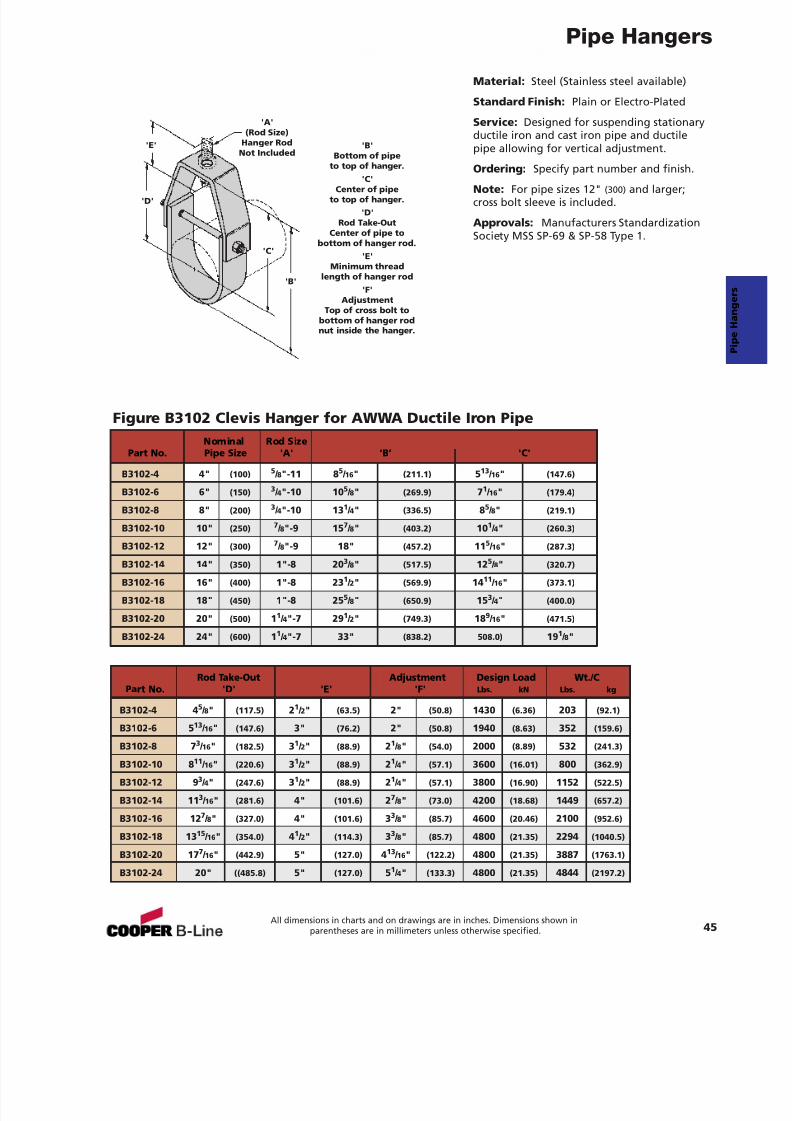
Material: Steel (Stainless steel available)
Standard Finish: Plain or Electro-Plated
Service: Designed for suspending stationaryductile iron and cast iron pipe and ductilepipe allowing for vertical adjustment.
Ordering: Specify part number and finish.
Note: For pipe sizes 12" (300) and larger;cross bolt sleeve is included.
Approvals: Manufacturers StandardizationSociety MSS SP-69 & SP-58 Type 1.
Figure B3102 Clevis Hanger for AWWA Ductile Iron Pipe
'B'
'D'
'C'
'E'
'A'(Rod Size)
Hanger RodNot Included
'B'Bottom of pipe
to top of hanger.'C'
Center of pipeto top of hanger.
'D'Rod Take-Out
Center of pipe tobottom of hanger rod.
'E'Minimum thread
length of hanger rod'F'
AdjustmentTop of cross bolt to
bottom of hanger rodnut inside the hanger.
Nominal Rod SizePart No. Pipe Size 'A' ‘B’ 'C'
B3102-4 4" (100) 5 / 8"-11 8 5 / 16 " (211.1) 513 / 16 " (147.6)
B3102-6 6" (150) 3 / 4"-10 10 5 / 8" (269.9) 71 / 16 " (179.4)
B3102-8 8" (200) 3 / 4"-10 13 1 / 4" (336.5) 85 / 8" (219.1)
B3102-10 10" (250) 7 / 8"-9 15 7 / 8" (403.2) 10 1 / 4" (260.3)
B3102-12 12" (300) 7 / 8"-9 18" (457.2) 11 5 / 16 " (287.3)
B3102-14 14" (350) 1"-8 20 3 / 8" (517.5) 12 5 / 8" (320.7)
B3102-16 16" (400) 1"-8 23 1 / 2" (569.9) 14 11 / 16 " (373.1)
B3102-18 18" (450) 1"-8 25 5 / 8" (650.9) 15 3 / 4" (400.0)
B3102-20 20" (500) 11 / 4"-7 29 1 / 2" (749.3) 18 9 / 16 " (471.5)
B3102-24 24" (600) 11 / 4"-7 33" (838.2) 508.0) 19 1 / 8"
Rod Take-Out Adjustment Design Load Wt./CPart No. 'D' 'E' 'F' Lbs. kN Lbs. kg
B3102-4 4 5 / 8" (117.5) 21 / 2" (63.5) 2" (50.8) 1430 (6.36) 203 (92.1)
B3102-6 5 13 / 16 " (147.6) 3" (76.2) 2" (50.8) 1940 (8.63) 352 (159.6)
B3102-8 7 3 / 16 " (182.5) 31 / 2" (88.9) 21 / 8" (54.0) 2000 (8.89) 532 (241.3)
B3102-10 8 11 / 16 " (220.6) 31 / 2" (88.9) 21 / 4" (57.1) 3600 (16.01) 800 (362.9)
B3102-12 9 3 / 4" (247.6) 31 / 2" (88.9) 21 / 4" (57.1) 3800 (16.90) 1152 (522.5)
B3102-14 11 3 / 16 " (281.6) 4" (101.6) 27 / 8" (73.0) 4200 (18.68) 1449 (657.2)
B3102-16 12 7 / 8" (327.0) 4" (101.6) 33 / 8" (85.7) 4600 (20.46) 2100 (952.6)
B3102-18 13 15 / 16 " (354.0) 41 / 2" (114.3) 33 / 8" (85.7) 4800 (21.35) 2294 (1040.5)
B3102-20 17 7 / 16 " (442.9) 5" (127.0) 413 / 16 " (122.2) 4800 (21.35) 3887 (1763.1)
B3102-24 20" ((485.8) 5" (127.0) 51 / 4" (133.3) 4800 (21.35) 4844 (2197.2)
7/18/2019 PH Pipe Hanger Catalog
http://slidepdf.com/reader/full/ph-pipe-hanger-catalog 48/224
Pipe Hangers
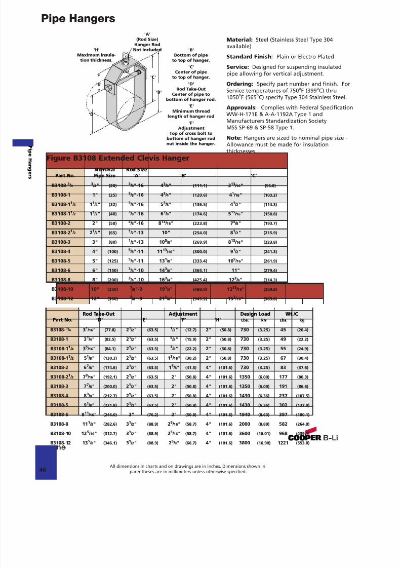
Material: Steel (Stainless Steel Type 304available)
Standard Finish: Plain or Electro-Plated
Service: Designed for suspending insulatedpipe allowing for vertical adjustment.
Ordering: Specify part number and finish. ForService temperatures of 750 oF (399 oC) thru1050 oF (565 oC) specify Type 304 Stainless Steel.
Approvals: Complies with Federal SpecificationWW-H-171E & A-A-1192A Type 1 andManufacturers Standardization SocietyMSS SP-69 & SP-58 Type 1.
Note: Hangers are sized to nominal pipe size -Allowance must be made for insulationthicknesses.
Figure B3108 Extended Clevis Hanger
'B'
'D'
'C'
'E'
'A'(Rod Size)
Hanger RodNot Included'H'
Maximum insula-tion thickness.
'B'Bottom of pipe
to top of hanger.'C'
Center of pipeto top of hanger.
'D'Rod Take-Out
Center of pipe tobottom of hanger rod.
'E'Minimum thread
length of hanger rod'F'
AdjustmentTop of cross bolt to
bottom of hanger rodnut inside the hanger.
Nominal Rod SizePart No. Pipe Size 'A' 'B' ‘C’
B3108-3
/ 43
/ 4" (20)3
/ 8"-16 43
/ 8" (111.1) 313
/ 16 " (96.8)B3108-1 1" (25) 3 / 8"-16 4 3 / 4" (120.6) 41 / 16 " (103.2)
B3108-1 1 / 4 11 / 4" (32) 3 / 8"-16 5 3 / 8" (136.5) 41 / 2" (114.3)
B3108-1 1 / 2 11 / 2" (40) 3 / 8"-16 6 7 / 8" (174.6) 515 / 16 " (150.8)
B3108-2 2" (50) 3 / 8"-16 8 13 / 16 " (223.8) 75 / 8" (193.7)
B3108-2 1 / 2 21 / 2" (65) 1 / 2"-13 10" (254.0) 81 / 2" (215.9)
B3108-3 3" (80) 1 / 2"-13 10 5 / 8" (269.9) 813 / 16 " (223.8)
B3108-4 4" (100) 5 / 8"-11 11 13 / 16 " (300.0) 91 / 2" (241.3)
B3108-5 5" (125) 5 / 8"-11 13 1 / 8" (333.4) 10 5 / 16 " (261.9)
B3108-6 6" (150) 3 / 4"-10 14 3 / 8" (365.1) 11" (279.4)
B3108-8 8" (200)3
/ 4"-10 163
/ 4" (425.4) 123
/ 8" (314.3)B3108-10 10" (250) 7 / 8"-9 19 1 / 4" (488.9) 13 13 / 16 " (350.8)
B3108-12 12" (300) 7 / 8"-9 21 5 / 8" (549.3) 15 3 / 16 " (385.8)
Rod Take-Out Adjustment Design Load Wt./CPart No. 'D' 'E' 'F' 'H' Lbs. kN Lbs. kg
B3108- 3 / 4 31 / 16 " (77.8) 21 / 2" (63.5) 1 / 2" (12.7) 2" (50.8) 730 (3.25) 45 (20.4)
B3108-1 3 1 / 4" (82.5) 21 / 2" (63.5) 5 / 8" (15.9) 2" (50.8) 730 (3.25) 49 (22.2)
B3108-1 1 / 4 35 / 16 " (84.1) 21 / 2" (63.5) 7 / 8" (22.2) 2" (50.8) 730 (3.25) 55 (24.9)
B3108-1 1 / 2 51 / 8" (130.2) 21 / 2" (63.5) 13 / 16 " (30.2) 2" (50.8) 730 (3.25) 67 (30.4)
B3108-2 6 7 / 8" (174.6) 21 / 2" (63.5) 15 / 8" (41.3) 4" (101.6) 730 (3.25) 83 (37.6)
B3108-2 1 / 2 79 / 16 " (192.1) 21 / 2" (63.5) 2" (50.8) 4" (101.6) 1350 (6.00) 177 (80.3)
B3108-3 7 7 / 8" (200.0) 21 / 2" (63.5) 2" (50.8) 4" (101.6) 1350 (6.00) 191 (86.6)
B3108-4 8 3 / 8" (212.7) 21 / 2" (63.5) 2" (50.8) 4" (101.6) 1430 (6.36) 237 (107.5)
B3108-5 9 1 / 8" (231.8) 21 / 2" (63.5) 2" (50.8) 4" (101.6) 1430 (6.36) 302 (137.0)
B3108-6 9 11 / 16 " (246.0) 3" (76.2) 2" (50.8) 4" (101.6) 1940 (8.63) 397 (180.1)
B3108-8 11 1 / 8" (282.6) 31 / 2" (88.9) 25 / 16 " (58.7) 4" (101.6) 2000 (8.89) 582 (264.0)
B3108-10 12 5 / 16 " (312.7) 31 / 2" (88.9) 25 / 16 " (58.7) 4" (101.6) 3600 (16.01) 968 (439.1)
B3108-12 13 5 / 8" (346.1) 31 / 2" (88.9) 25 / 8" (66.7) 4" (101.6) 3800 (16.90) 1221 (553.8)
46All dimensions in charts and on drawings are in inches. Dimensions shown in
parentheses are in millimeters unless otherwise specified.
P i peHanger s
7/18/2019 PH Pipe Hanger Catalog
http://slidepdf.com/reader/full/ph-pipe-hanger-catalog 49/224
Pipe Hangers
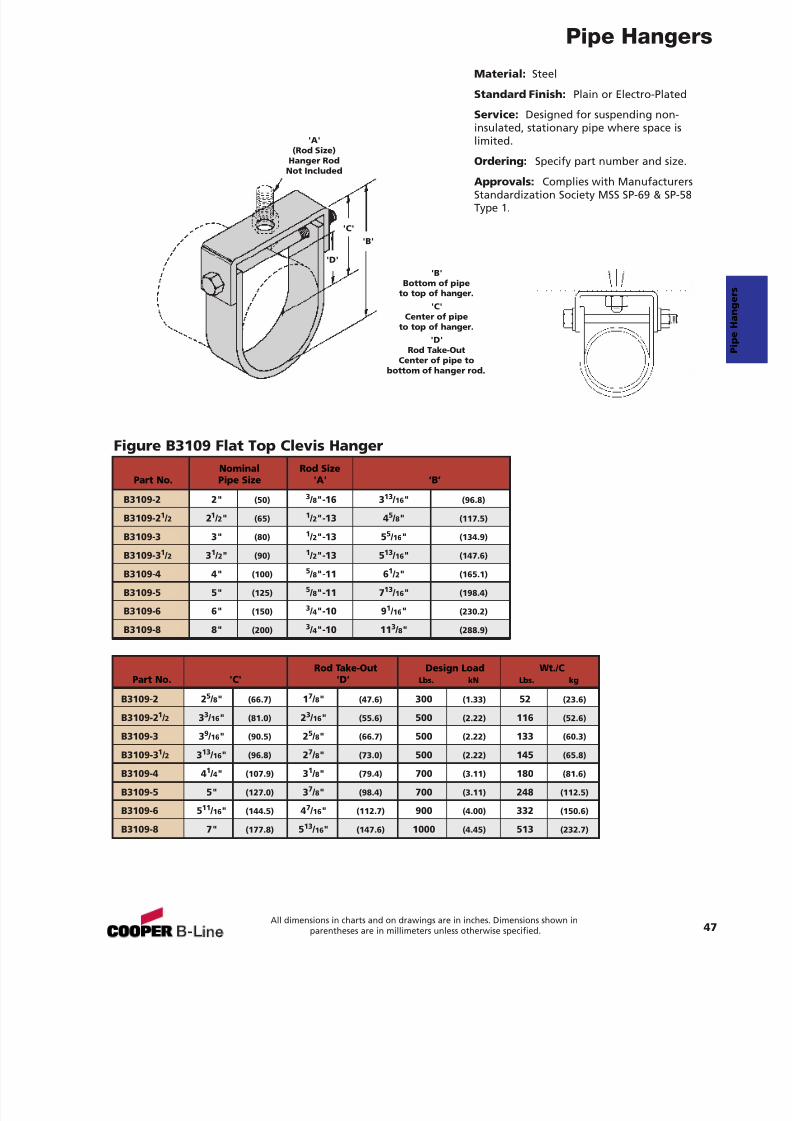
Figure B3109 Flat Top Clevis Hanger
Material: Steel
Standard Finish: Plain or Electro-Plated
Service: Designed for suspending non-insulated, stationary pipe where space islimited.
Ordering: Specify part number and size.
Approvals: Complies with ManufacturersStandardization Society MSS SP-69 & SP-58Type 1.
'B'
'D'
'C'
'A'(Rod Size)
Hanger RodNot Included
'B'Bottom of pipe
to top of hanger.'C'
Center of pipeto top of hanger.
'D'Rod Take-Out
Center of pipe to
bottom of hanger rod.
Nominal Rod SizePart No. Pipe Size 'A' ‘B’
B3109-2 2" (50) 3 / 8"-16 3 13 / 16 " (96.8)
B3109-2 1 / 2 21 / 2" (65) 1 / 2"-13 4 5 / 8" (117.5)
B3109-3 3" (80) 1 / 2"-13 5 5 / 16 " (134.9)
B3109-3 1 / 2 31 / 2" (90) 1 / 2"-13 5 13 / 16 " (147.6)
B3109-4 4" (100) 5 / 8"-11 6 1 / 2" (165.1)
B3109-5 5" (125) 5 / 8"-11 7 13 / 16 " (198.4)
B3109-6 6" (150) 3 / 4"-10 9 1 / 16 " (230.2)
B3109-8 8" (200) 3 / 4"-10 11 3 / 8" (288.9)
Rod Take-Out Design Load Wt./CPart No. 'C' 'D' Lbs. kN Lbs. kg
B3109-2 2 5 / 8" (66.7) 17 / 8" (47.6) 300 (1.33) 52 (23.6)
B3109-2 1 / 2 33 / 16 " (81.0) 23 / 16 " (55.6) 500 (2.22) 116 (52.6)
B3109-3 3 9 / 16 " (90.5) 25 / 8" (66.7) 500 (2.22) 133 (60.3)
B3109-3 1 / 2 313 / 16" (96.8) 27 / 8" (73.0) 500 (2.22) 145 (65.8)
B3109-4 4 1 / 4" (107.9) 31 / 8" (79.4) 700 (3.11) 180 (81.6)
B3109-5 5" (127.0) 37 / 8" (98.4) 700 (3.11) 248 (112.5)
B3109-6 5 11 / 16" (144.5) 47 / 16 " (112.7) 900 (4.00) 332 (150.6)
B3109-8 7" (177.8) 513 / 16" (147.6) 1000 (4.45) 513 (232.7)
47All dimensions in charts and on drawings are in inches. Dimensions shown in
parentheses are in millimeters unless otherwise specified.
7/18/2019 PH Pipe Hanger Catalog
http://slidepdf.com/reader/full/ph-pipe-hanger-catalog 50/224
Pipe Hangers
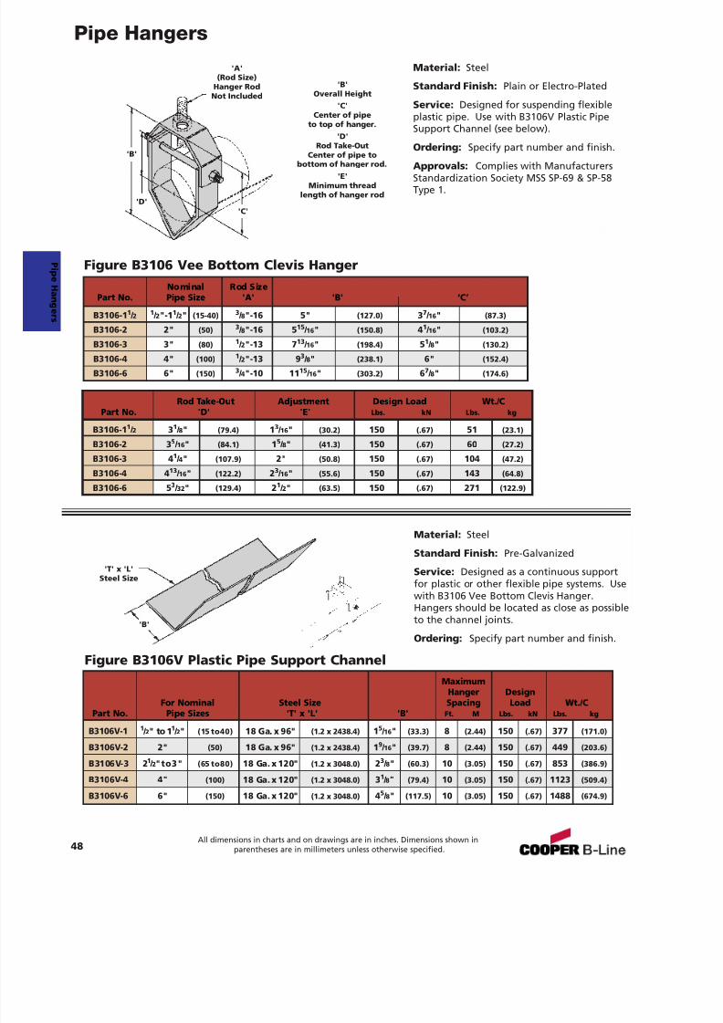
Material: Steel
Standard Finish: Plain or Electro-Plated
Service: Designed for suspending flexibleplastic pipe. Use with B3106V Plastic PipeSupport Channel (see below).
Ordering: Specify part number and finish.
Approvals: Complies with ManufacturersStandardization Society MSS SP-69 & SP-58Type 1.
Figure B3106 Vee Bottom Clevis Hanger
Material: Steel
Standard Finish: Pre-Galvanized
Service: Designed as a continuous supportfor plastic or other flexible pipe systems. Usewith B3106 Vee Bottom Clevis Hanger.Hangers should be located as close as possibleto the channel joints.
Ordering: Specify part number and finish.
Figure B3106V Plastic Pipe Support Channel
'B'
'B'
'D'
'T' x 'L'Steel Size
'C'
'A'(Rod Size)
Hanger RodNot Included
'B'Overall Height
'C'Center of pipe
to top of hanger.'D'
Rod Take-OutCenter of pipe to
bottom of hanger rod.'E'
Minimum threadlength of hanger rod
MaximumHanger Design
For Nominal Steel Size Spacing Load Wt./CPart No. Pipe Sizes 'T' x 'L' 'B' Ft. M Lbs. kN Lbs. kg
B3106V-1 1 / 2" to 1 1 / 2" (15 to40) 18 Ga. x 96" (1.2 x 2438.4) 15 / 16 " (33.3) 8 (2.44) 150 (.67) 377 (171.0)
B3106V-2 2" (50) 18 Ga. x 96" (1.2 x 2438.4) 19 / 16 " (39.7) 8 (2.44) 150 (.67) 449 (203.6)
B3106V-3 2 1 / 2"to3" (65 to80) 18 Ga. x 120" (1.2 x 3048.0) 23 / 8" (60.3) 10 (3.05) 150 (.67) 853 (386.9)
B3106V-4 4" (100) 18 Ga. x 120" (1.2 x 3048.0) 31 / 8" (79.4) 10 (3.05) 150 (.67) 1123 (509.4)
B3106V-6 6" (150) 18 Ga. x 120" (1.2 x 3048.0) 45 / 8" (117.5) 10 (3.05) 150 (.67) 1488 (674.9)
Rod Take-Out Adjustment Design Load Wt./CPart No. 'D' 'E' Lbs. kN Lbs. kg
B3106-1 1 / 2 31 / 8" (79.4) 13 / 16 " (30.2) 150 (.67) 51 (23.1)
B3106-2 3 5 / 16" (84.1) 15 / 8" (41.3) 150 (.67) 60 (27.2)
B3106-3 4 1 / 4" (107.9) 2" (50.8) 150 (.67) 104 (47.2)
B3106-4 4 13 / 16 " (122.2) 23 / 16 " (55.6) 150 (.67) 143 (64.8)
B3106-6 5 3 / 32" (129.4) 21 / 2" (63.5) 150 (.67) 271 (122.9)
Nominal Rod SizePart No. Pipe Size 'A' 'B' ‘C’
B3106-1 1 / 2 1 / 2"-1 1 / 2" (15-40) 3 / 8"-16 5" (127.0) 37 / 16 " (87.3)
B3106-2 2" (50) 3 / 8"-16 5 15 / 16 " (150.8) 41 / 16 " (103.2)
B3106-3 3" (80) 1 / 2"-13 7 13 / 16 " (198.4) 51 / 8" (130.2)
B3106-4 4" (100) 1 / 2"-13 9 3 / 8" (238.1) 6" (152.4)
B3106-6 6" (150) 3 / 4"-10 11 15 / 16 " (303.2) 67 / 8" (174.6)
48All dimensions in charts and on drawings are in inches. Dimensions shown in
parentheses are in millimeters unless otherwise specified.
P i peHanger s
7/18/2019 PH Pipe Hanger Catalog
http://slidepdf.com/reader/full/ph-pipe-hanger-catalog 51/224
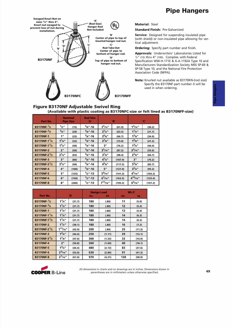
Pipe Hangers
49All dimensions in charts and on drawings are in inches. Dimensions shown in
parentheses are in millimeters unless otherwise specified.
Material: Steel
Standard Finish: Pre-Galvanized
Service: Designed for suspending insulated pipe(with shield) or non-insulated pipe allowing for ver-tical adjustment.
Ordering: Specify part number and finish.
Approvals: Underwriters' Laboratories Listed for1 / 2" (15) thru 4" (100) . Complies with FederalSpecification WW-H-171E & A-A-1192A Type 10 andManufacturers Standardization Society MSS SP-69 &SP-58 Type 10, and the National Fire ProtectionAssociation Code (NFPA).
Note: Knurled nut available as B3170KN-(rod size)Specify the B3170NF part number it will beused in when ordering.
Figure B3170NF Adjustable Swivel Ring(Available with plastic coating as B3170NFC-size or felt lined as B3170NFF-size)
'A'(Rod Size)
Hanger RodNot Included
Swaged Knurl Nut onsizes 1 / 2” thru 4”.
Knurl nut swaged toprevent loss of nut during
installation.
'B''D' 'C'
'B'Center of pipe to top ofknurled hanger rod nut.
'C'Rod Take-Out
Center of pipe to
bottom of hanger rod.'D'
Top of pipe to bottom ofhanger rod nut.
Nominal Rod SizePart No. Pipe Size 'A' 'B' 'C'
B3170NF- 1 / 2 1 / 2" (15) 3 / 8"-16 2 7 / 16 " (61.9) 13 / 16 " (30.2)
B3170NF- 3 / 4 3 / 4" (20) 3 / 8"-16 2 1 / 2" (63.5) 11 / 4" (31.7)
B3170NF-1 1" (25) 3 / 8"-16 2 5 / 8" (66.7) 13 / 8" (34.9)
B3170NF-1 1 / 4 11 / 4" (32) 3 / 8"-16 2 7 / 8" (73.0) 15 / 8" (41.2)
B3170NF-1 1 / 2 11 / 2" (40) 3 / 8"-16 3" (76.2) 13 / 4" (44.4)
B3170NF-2 2" (50) 3 / 8"-16 3 7 / 16 " (87.2) 23 / 16 " (55.6)
B3170NF-2 1 / 2 21 / 2" (65) 3 / 8"-16 3 7 / 8" (98.4) 25 / 8" (66.7)
B3170NF-3 3" (80) 3 / 8"-16 4 1 / 4" (107.9) 3" (76.2)
B3170NF-3 1 / 2 31 / 2" (90) 3 / 8"-16 4 5 / 8" (117.5) 33 / 8" (85.7)
B3170NF-4 4" (100) 3 / 8"-16 5" (127.0) 33 / 4" (95.2)
B3170NF-5 5" (125) 1 / 2"-13 5 9 / 16 " (141.3) 41 / 16 " (103.2)
B3170NF-6 6" (150) 1 / 2"-13 6 7 / 16 " (163.5) 415 / 16 " (125.4)
B3170NF-8 8" (200) 1 / 2"-13 7 11 / 16 " (195.3) 63 / 16 " (157.2)
Design Load Wt./CPart No. 'D' Lbs. kN Lbs. kg
B3170NF- 1 / 2 11 / 4" (31.7) 180 (.80) 11 (5.0)
B3170NF- 3 / 4 11 / 4" (31.7) 180 (.80) 12 (5.4)
B3170NF-1 1 1 / 4" (31.7) 180 (.80) 13 (5.9)
B3170NF-1 1 / 4 11 / 4" (31.7) 180 (.80) 14 (6.3)
B3170NF-1 1 / 2 11 / 4" (31.7) 180 (.80) 14 (6.3)
B3170NF-2 1 1 / 2" (38.1) 180 (.80) 16 (7.2)
B3170NF-2 1 / 2 111 / 16 " (42.9) 200 (.89) 25 (11.3)
B3170NF-3 1 3 / 4" (44.4) 250 (1.11) 29 (13.1)
B3170NF-3 1 / 2 17 / 8" (47.6) 300 (1.33) 33 (14.9)
B3170NF-4 2" (50.8) 360 (1.60) 40 (18.1)
B3170NF-5 1 3 / 4" (44.4) 480 (2.13) 83 (37.6)
B3170NF-6 2 3 / 16 " (53.0) 630 (2.80) 91 (41.3)
B3170NF-8 2 7 / 16 " (61.9) 970 (4.31) 130 (58.9)
B3170NFC
B3170NF
B3170NFF
UL®
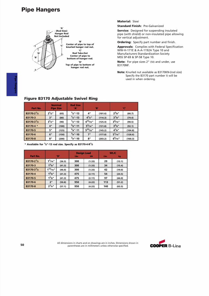
7/18/2019 PH Pipe Hanger Catalog
http://slidepdf.com/reader/full/ph-pipe-hanger-catalog 52/224
Pipe Hangers
Material: Steel
Standard Finish: Pre-Galvanized
Service: Designed for suspending insulatedpipe (with shield) or non-insulated pipe allowingfor vertical adjustment.
Ordering: Specify part number and finish.
Approvals: Complies with Federal SpecificationWW-H-171E & A-A-1192A Type 10 andManufacturers Standardization SocietyMSS SP-69 & SP-58 Type 10.
Note: For pipe sizes 2" (50) and under, useB3170NF.
Note: Knurled nut available as B3170KN-(rod size)Specify the B3170 part number it will beused in when ordering.
Figure B3170 Adjustable Swivel Ring
50All dimensions in charts and on drawings are in inches. Dimensions shown in
parentheses are in millimeters unless otherwise specified.
* Available for 1 / 2"-13 rod size. Specify as B3170-4-R 1 / 2
Nominal Rod SizePart No. Pipe Size 'A' 'B' 'C'
B3170-2 1 / 2 21 / 2" (65) 1 / 2"-13 4" (101.6) 25 / 8" (66.7)
B3170-3 3" (80) 1 / 2"-13 4 1 / 2" (114.3) 31 / 8" (79.4)
B3170-3 1 / 2 31 / 2" (90) 1 / 2"-13 4 15 / 16 " (125.4) 39 / 16 " (90.5)
B3170-4 * 4" (100) 5 / 8"-11 5 3 / 16 " (131.8) 35 / 8" (92.1)
B3170-5 5" (125) 5 / 8"-11 5 23 / 32 " (145.2) 41 / 8" (104.8)
B3170-6 6" (150) 3 / 4"-10 7" (177.8) 51 / 16 " (128.6)
B3170-8 8" (200) 3 / 4"-10 8" (203.2) 65 / 16 " (160.3)
Design Load Wt./CPart No. 'D' Lbs. kN Lbs. kg
B3170-2 1 / 2 17 / 16 " (36.5) 300 (1.33) 29 (13.1)
B3170-3 1 5 / 8" (41.3) 300 (1.33) 34 (15.4)
B3170-3 1 / 2 113 / 16 " (46.0) 300 (1.33) 42 (19.0)
B3170-4 1 5 / 8" (41.3) 475 (2.11) 54 (24.5)
B3170-5 1 5 / 8" (41.3) 475 (2.11) 97 (44.0)
B3170-6 2" (50.8) 950 (4.22) 113 (51.2)
B3170-8 2 1 / 4" (57.1) 950 (4.22) 140 (63.5)
P i peHanger s
'A'(Rod Size)
Hanger RodNot Included
'B'
'D'
'C'
'B'Center of pipe to top ofknurled hanger rod nut.
'C'Rod Take-Out
Center of pipe tobottom of hanger rod.
'D'Top of pipe to bottom of
hanger rod nut.
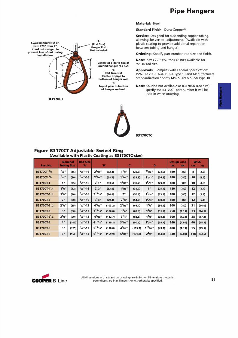
7/18/2019 PH Pipe Hanger Catalog
http://slidepdf.com/reader/full/ph-pipe-hanger-catalog 53/224
Pipe Hangers
Figure B3170CT Adjustable Swivel Ring(Available with Plastic Coating as B3170CTC-size)
Material: Steel
Standard Finish: Dura-Copper ®
Service: Designed for suspending copper tubing,allowing for vertical adjustment. (Available withplastic coating to provide additional separationbetween tubing and hanger).
Ordering: Specify part number, rod size and finish.
Note: Sizes 2 1 / 2" (65) thru 4" (100) available for3 / 8"-16 rod size.
Approvals: Complies with Federal SpecificationsWW-H-171E & A-A-1192A Type 10 and ManufacturersStandardization Society MSS SP-69 & SP-58 Type 10.
Note: Knurled nut available as B3170KN-(rod size)Specify the B3170CT part number it will beused in when ordering.
B3170CT
B3170CTC
'A'(Rod Size)
Hanger RodNot Included
'B''D' 'C'
'B'Center of pipe to top ofknurled hanger rod nut.
'C'Rod Take-Out
Center of pipe tobottom of hanger rod.
'D'Top of pipe to bottom
of hanger rod nut.
Nominal Rod Size Design Load Wt./CPart No. Tubing Size 'A' 'B' 'C' 'D' Lbs. kN Lbs. kg
B3170CT- 1 / 2 1 / 2" (15) 3 / 8"-16 2 1 / 16 " (52.4) 11 / 8" (28.6) 31 / 32 " (24.6) 180 (.80) 8 (3.6)
B3170CT- 3 / 4 3 / 4" (20) 3 / 8"-16 2 5 / 16 " (58.7) 15 / 16 " (33.3) 11 / 32 " (26.2) 180 (.80) 10 (4.5)
B3170CT-1 1" (25) 3 / 8"-16 2 1 / 2" (63.5) 19 / 16 " (39.7) 15 / 32 " (29.3) 180 (.80) 10 (4.5)
B3170CT-1 1 / 4 11 / 4" (32) 3 / 8"-16 2 1 / 2" (63.5) 19 / 16 " (39.7) 1" (25.4) 180 (.80) 12 (5.4)
B3170CT-1 1 / 2 11 / 2" (40) 3 / 8"-16 2 15 / 16 " (74.6) 2" (50.8) 15 / 16 " (33.3) 180 (.80) 12 (5.4)
B3170CT-2 2" (50) 3 / 8"-16 3 1 / 8" (79.4) 21 / 8" (54.0) 13 / 16 " (30.2) 180 (.80) 12 (5.4)
B3170CT-2 1 / 2 21 / 2" (65) 1 / 2"-13 4 1 / 16 " (103.2) 29 / 16 " (65.1) 13 / 8" (34.9) 200 (.80) 31 (14.0)
B3170CT-3 3" (80) 1 / 2"-13 3 15 / 16 " (100.0) 33 / 4" (69.8) 11 / 4" (31.7) 250 (1.11) 33 (14.9)
B3170CT-3 1 / 2 31 / 2" (90) 1 / 2"-13 4 7 / 16 " (112.7) 31 / 4" (82.5) 11 / 2" (38.1) 300 (1.33) 38 (17.2)
B3170CT-4 4" (100)1
/ 2"-13 411
/ 16 " (119.1) 39
/ 16 " (90.5) 19
/ 16 " (39.7) 360 (1.60) 40 (18.1)B3170CT-5 5" (125) 1 / 2"-13 5 15 / 16 " (150.8) 45 / 16 " (109.5) 125 / 32 " (45.2) 480 (2.13) 95 (43.1)
B3170CT-6 6" (150) 1 / 2"-13 6 11 / 16 " (169.9) 53 / 16 " (131.8) 21 / 8" (54.0) 630 (2.80) 118 (53.5)
51All dimensions in charts and on drawings are in inches. Dimensions shown in
parentheses are in millimeters unless otherwise specified.
Swaged Knurl Nut onsizes 2 1 / 2” thru 4”.
Knurl nut swaged toprevent loss of nut during
installation.
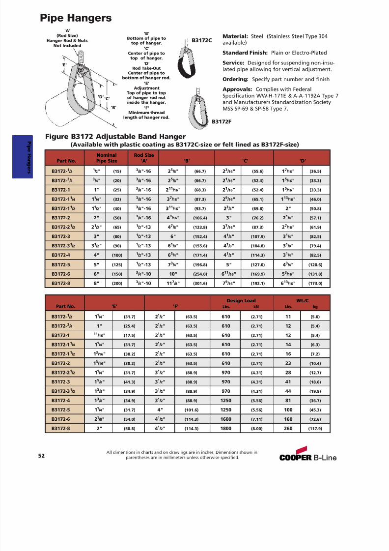
7/18/2019 PH Pipe Hanger Catalog
http://slidepdf.com/reader/full/ph-pipe-hanger-catalog 54/224
Pipe Hangers
Material: Steel (Stainless Steel Type 304available)
Standard Finish: Plain or Electro-Plated
Service: Designed for suspending non-insu-lated pipe allowing for vertical adjustment.
Ordering: Specify part number and finish
Approvals: Complies with FederalSpecification WW-H-171E & A-A-1192A Type 7and Manufacturers Standardization SocietyMSS SP-69 & SP-58 Type 7.
Figure B3172 Adjustable Band Hanger(Available with plastic coating as B3172C-size or felt lined as B3172F-size)
'B'
'D' 'C'
'E'
'A'(Rod Size)
Hanger Rod & NutsNot Included
'B'Bottom of pipe to
top of hanger.'C'
Center of pipe totop of hanger.
'D'Rod Take-Out
Center of pipe tobottom of hanger rod.
'E'Adjustment
Top of pipe to topof hanger rod nutinside the hanger.
'F'Minimum thread
length of hanger rod.
Design Load Wt./CPart No. 'E' 'F' Lbs. kN Lbs. kg
B3172- 1 / 2 11 / 4" (31.7) 21 / 2" (63.5) 610 (2.71) 11 (5.0)
B3172- 3 / 4 1" (25.4) 21 / 2" (63.5) 610 (2.71) 12 (5.4)
B3172-1 11 / 16 " (17.5) 21 / 2" (63.5) 610 (2.71) 12 (5.4)
B3172-1 1 / 4 11 / 4" (31.7) 21 / 2" (63.5) 610 (2.71) 14 (6.3)
B3172-1 1 / 2 13 / 16 " (30.2) 21 / 2" (63.5) 610 (2.71) 16 (7.2)
B3172-2 13 / 16 " (30.2) 2
1 / 2" (63.5) 610 (2.71) 23 (10.4)
B3172-2 1 / 2 11 / 4" (31.7) 31 / 2" (88.9) 970 (4.31) 28 (12.7)
B3172-3 1 5 / 8" (41.3) 31 / 2" (88.9) 970 (4.31) 41 (18.6)
B3172-3 1 / 2 13 / 8" (34.9) 31 / 2" (88.9) 970 (4.31) 44 (19.9)
B3172-4 1 3 / 8" (34.9) 31 / 2" (88.9) 1250 (5.56) 81 (36.7)
B3172-5 1 1 / 4" (31.7) 4" (101.6) 1250 (5.56) 100 (45.3)
B3172-6 2 1 / 8" (54.0) 41 / 2" (114.3) 1600 (7.11) 160 (72.6)
B3172-8 2" (50.8) 41 / 2" (114.3) 1800 (8.00) 260 (117.9)
Nominal Rod SizePart No. Pipe Size 'A' 'B' 'C' 'D'
B3172- 1 / 2 1 / 2" (15) 3 / 8"-16 2 5 / 8" (66.7) 23 / 16 " (55.6) 17 / 16 " (36.5)
B3172-3
/ 43
/ 4" (20)3
/ 8"-16 25
/ 8" (66.7) 21
/ 16 " (52.4) 15
/ 16 " (33.3)B3172-1 1" (25) 3 / 8"-16 2 11 / 16 " (68.3) 21 / 16 " (52.4) 15 / 16 " (33.3)
B3172-1 1 / 4 11 / 4" (32) 3 / 8"-16 3 7 / 16 " (87.3) 29 / 16 " (65.1) 113 / 16 " (46.0)
B3172-1 1 / 2 11 / 2" (40) 3 / 8"-16 3 11 / 16 " (93.7) 23 / 4" (69.8) 2" (50.8)
B3172-2 2" (50) 3 / 8"-16 4 3 / 16 " (106.4) 3" (76.2) 21 / 4" (57.1)
B3172-2 1 / 2 21 / 2" (65) 1 / 2"-13 4 7 / 8" (123.8) 37 / 16 " (87.3) 27 / 16 " (61.9)
B3172-3 3" (80) 1 / 2"-13 6" (152.4) 41 / 4" (107.9) 31 / 4" (82.5)
B3172-3 1 / 2 31 / 2" (90) 1 / 2"-13 6 1 / 8" (155.6) 41 / 8" (104.8) 31 / 8" (79.4)
B3172-4 4" (100) 1 / 2"-13 6 3 / 4" (171.4) 41 / 2" (114.3) 31 / 4" (82.5)
B3172-5 5" (125) 1 / 2"-13 7 3 / 4" (196.8) 5" (127.0) 43 / 4" (120.6)
B3172-6 6" (150) 3 / 4"-10 10" (254.0) 611 / 16 " (169.9) 53 / 16 " (131.8)
B3172-8 8" (200) 3 / 4"-10 11 7 / 8" (301.6) 79 / 16 " (192.1) 613 / 16 " (173.0)
B3172C
B3172F
52All dimensions in charts and on drawings are in inches. Dimensions shown in
parentheses are in millimeters unless otherwise specified.
P i peHanger s
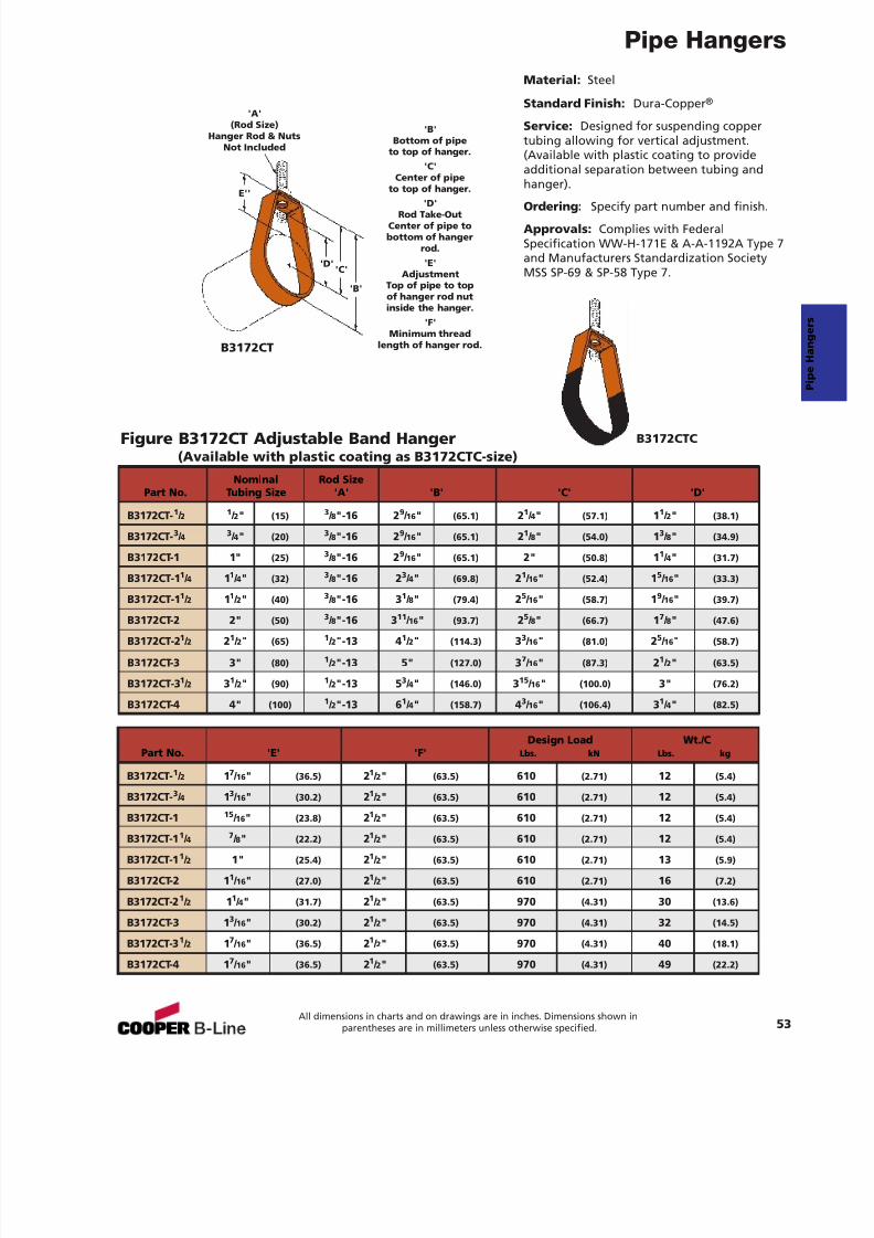
7/18/2019 PH Pipe Hanger Catalog
http://slidepdf.com/reader/full/ph-pipe-hanger-catalog 55/224
Pipe Hangers
Figure B3172CT Adjustable Band Hanger(Available with plastic coating as B3172CTC-size)
Material: Steel
Standard Finish: Dura-Copper ®
Service: Designed for suspending coppertubing allowing for vertical adjustment.(Available with plastic coating to provideadditional separation between tubing andhanger).
Ordering: Specify part number and finish.Approvals: Complies with FederalSpecification WW-H-171E & A-A-1192A Type 7and Manufacturers Standardization SocietyMSS SP-69 & SP-58 Type 7.
B3172CT
B3172CTC
'B'
'D'
E''
'C'
'B'Bottom of pipe
to top of hanger.'C'
Center of pipeto top of hanger.
'D'Rod Take-OutCenter of pipe tobottom of hanger
rod.'E'
AdjustmentTop of pipe to topof hanger rod nutinside the hanger.
'F'Minimum thread
length of hanger rod.
Nominal Rod SizePart No. Tubing Size 'A' 'B' 'C' 'D'
B3172CT- 1 / 2 1 / 2" (15) 3 / 8"-16 2 9 / 16 " (65.1) 21 / 4" (57.1) 11 / 2" (38.1)
B3172CT- 3 / 4 3 / 4" (20) 3 / 8"-16 2 9 / 16 " (65.1) 21 / 8" (54.0) 13 / 8" (34.9)
B3172CT-1 1" (25) 3 / 8"-16 2 9 / 16 " (65.1) 2" (50.8) 11 / 4" (31.7)
B3172CT-1 1 / 4 11 / 4" (32) 3 / 8"-16 2 3 / 4" (69.8) 21 / 16 " (52.4) 15 / 16 " (33.3)
B3172CT-1 1 / 2 11 / 2" (40) 3 / 8"-16 3 1 / 8" (79.4) 25 / 16 " (58.7) 19 / 16 " (39.7)
B3172CT-2 2" (50) 3 / 8"-16 3 11 / 16 " (93.7) 25 / 8" (66.7) 17 / 8" (47.6)
B3172CT-2 1 / 2 21 / 2" (65) 1 / 2"-13 4 1 / 2" (114.3) 33 / 16 " (81.0) 25 / 16 " (58.7)
B3172CT-3 3" (80) 1 / 2"-13 5" (127.0) 37 / 16 " (87.3) 21 / 2" (63.5)
B3172CT-3 1 / 2 31 / 2" (90) 1 / 2"-13 5 3 / 4" (146.0) 315 / 16 " (100.0) 3" (76.2)
B3172CT-4 4" (100) 1 / 2"-13 6 1 / 4" (158.7) 43 / 16 " (106.4) 31 / 4" (82.5)
Design Load Wt./CPart No. 'E' 'F' Lbs. kN Lbs. kg
B3172CT- 1 / 2 17 / 16 " (36.5) 21 / 2" (63.5) 610 (2.71) 12 (5.4)
B3172CT- 3 / 4 13 / 16 " (30.2) 21 / 2" (63.5) 610 (2.71) 12 (5.4)
B3172CT-115
/ 16 " (23.8) 21 / 2" (63.5) 610 (2.71) 12 (5.4)
B3172CT-1 1 / 4 7 / 8" (22.2) 21 / 2" (63.5) 610 (2.71) 12 (5.4)
B3172CT-1 1 / 2 1" (25.4) 21 / 2" (63.5) 610 (2.71) 13 (5.9)
B3172CT-2 1 1 / 16 " (27.0) 21 / 2" (63.5) 610 (2.71) 16 (7.2)
B3172CT-2 1 / 2 11 / 4" (31.7) 21 / 2" (63.5) 970 (4.31) 30 (13.6)
B3172CT-3 1 3 / 16 " (30.2) 21 / 2" (63.5) 970 (4.31) 32 (14.5)
B3172CT-3 1 / 2 17 / 16 " (36.5) 21 / 2" (63.5) 970 (4.31) 40 (18.1)
B3172CT-4 1 7 / 16 " (36.5) 21 / 2" (63.5) 970 (4.31) 49 (22.2)
53All dimensions in charts and on drawings are in inches. Dimensions shown in
parentheses are in millimeters unless otherwise specified.
'A'(Rod Size)
Hanger Rod & NutsNot Included
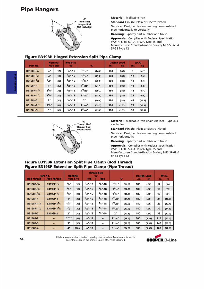
7/18/2019 PH Pipe Hanger Catalog
http://slidepdf.com/reader/full/ph-pipe-hanger-catalog 56/224
Pipe HangersMaterial: Malleable IronStandard Finish: Plain or Electro-PlatedService: Designed for suspending non-insulatedpipe horizontally or vertically.Ordering: Specify part number and finish.Approvals: Complies with Federal SpecificationWW-H-171E & A-A-1192A Type 25 andManufacturers Standardization Society MSS SP-69 &SP-58 Type 12.
Material: Malleable Iron (Stainless Steel Type 304available)
Standard Finish: Plain or Electro-Plated
Service: Designed for suspending non-insulatedpipe horizontally.
Ordering: Specify part number and finish.
Approvals: Complies with Federal SpecificationWW-H-171E & A-A-1192A Type 25 andManufacturers Standardization Society MSS SP-69 &SP-58 Type 12.
Figure B3198H Hinged Extension Split Pipe Clamp
Figure B3198R Extension Split Pipe Clamp (Rod Thread)Figure B3198P Extension Split Pipe Clamp (Pipe Thread)
'A'(Rod Size)
Hanger RodNot Included
'A'(Thread Size)Hanger Rod
Not Included
'C'
'C'
Thread SizePart No. Nominal 'A' Design Load Wt./C
Rod Thread Pipe Thread Pipe Size Rod Pipe 'C' Lbs. kN Lbs. kg
B3198R- 3 / 8 B3198P- 3 / 8 3 / 8" (10) 3 / 8"-16 1 / 4"-18 31 / 32 " (24.6) 180 (.80) 12 (5.4)
B3198R- 1 / 2 B3198P- 1 / 2 1 / 2" (15) 3 / 8"-16 1 / 4"-18 1 1 / 16 " (27.0) 180 (.80) 16 (7.2)
B3198R- 3 / 4 B3198P- 3 / 4 3 / 4" (20) 3 / 8"-16 1 / 4"-18 1 7 / 32 " (30.9) 180 (.80) 18 (8.1)
B3198R-1 B3198P-1 1" (25) 3 / 8"-16 1 / 4"-18 1 11 / 32 " (34.1) 180 (.80) 24 (10.9)
B3198R-1 1 / 4 B3198P-1 1 / 4 11 / 4" (32) 3 / 8"-16 1 / 4"-18 1 19 / 32 " (39.7) 180 (.80) 29 (13.1)
B3198R-1 1 / 2 B3198P-1 1 / 2 11 / 2" (40) 3 / 8"-16 1 / 4"-18 1 23 / 32 " (43.6) 180 (.80) 32 (14.5)
B3198R-2 B3198P-2 2" (50) 3 / 8"-16 1 / 4"-18 2" (50.8) 180 (.80) 39 (17.7)
B3198R-2 1 / 2 -- 21 / 2" (65) 1 / 2"-13 -- 2 11 / 32 " (59.5) 300 (1.33) 115 (52.1)
B3198R-3 -- 3" (80) 1 / 2"-13 -- 2 23 / 32 " (69.0) 300 (1.33) 140 (63.5)
B3198R-4 -- 4" (100) 1 / 2"-13 -- 3 11 / 32 " (84.9) 300 (1.33) 160 (72.6)
Nominal Rod Size Design Load Wt./CPart No. Pipe Size 'A' 'C' Lbs. kN Lbs. kg
B3198H- 3 / 8 3 / 8" (10) 3 / 8"-16 31 / 32 " (24.6) 180 (.80) 9 (4.1)
B3198H- 1 / 2 1 / 2" (15) 3 / 8"-16 1 1 / 16 " (27.0) 180 (.80) 12 (5.4)
B3198H- 3 / 4 3 / 4" (20) 3 / 8"-16 1 7 / 32 " (30.9) 180 (.80) 12 (5.4)
B3198H-1 1" (25) 3 / 8"-16 1 11 / 32 " (34.1) 180 (.80) 13 (5.9)
B3198H-1 1 / 4 11 / 4" (32) 3 / 8"-16 1 19 / 32 " (39.7) 180 (.80) 18 (8.1)
B3198H-1 1 / 2 11 / 2" (40) 3 / 8"-16 1 23 / 32 " (43.6) 180 (.80) 21 (9.5)
B3198H-2 2" (50) 3 / 8"-16 2" (50.8) 180 (.80) 44 (19.9)
B3198H-2 1 / 2 21 / 2" (65) 1 / 2"-13 2 11 / 32 " (59.5) 300 (1.33) 73 (33.1)
B3198H-3 3" (80) 1 / 2"-13 2 23 / 32 " (69.0) 300 (1.33) 95 (43.1)
54All dimensions in charts and on drawings are in inches. Dimensions shown in
parentheses are in millimeters unless otherwise specified.
P i peHanger s
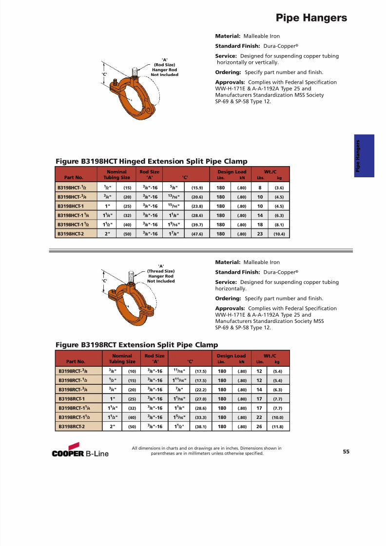
7/18/2019 PH Pipe Hanger Catalog
http://slidepdf.com/reader/full/ph-pipe-hanger-catalog 57/224
Pipe Hangers
Figure B3198HCT Hinged Extension Split Pipe Clamp
Figure B3198RCT Extension Split Pipe Clamp
Material: Malleable Iron
Standard Finish: Dura-Copper ®
Service: Designed for suspending copper tubinghorizontally or vertically.
Ordering: Specify part number and finish.
Approvals: Complies with Federal Specification
WW-H-171E & A-A-1192A Type 25 andManufacturers Standardization MSS SocietySP-69 & SP-58 Type 12.
Material: Malleable Iron
Standard Finish: Dura-Copper ®
Service: Designed for suspending copper tubinghorizontally.
Ordering: Specify part number and finish.
Approvals: Complies with Federal SpecificationWW-H-171E & A-A-1192A Type 25 andManufacturers Standardization Society MSSSP-69 & SP-58 Type 12.
'A'(Rod Size)
Hanger RodNot Included
'A'
(Thread Size)Hanger Rod
Not Included
'C'
'C'
Nominal Rod Size Design Load Wt./CPart No. Tubing Size 'A' 'C' Lbs. kN Lbs. kg
B3198HCT- 1 / 2 1 / 2" (15) 3 / 8"-16 5 / 8" (15.9) 180 (.80) 8 (3.6)
B3198HCT- 3 / 4 3 / 4" (20) 3 / 8"-16 13 / 16 " (20.6) 180 (.80) 10 (4.5)
B3198HCT-1 1" (25) 3 / 8"-16 15 / 16 " (23.8) 180 (.80) 10 (4.5)
B3198HCT-1 1 / 4 11 / 4" (32) 3 / 8"-16 1 1 / 8" (28.6) 180 (.80) 14 (6.3)
B3198HCT-1 1 / 2 11 / 2" (40) 3 / 8"-16 1 9 / 16 " (39.7) 180 (.80) 18 (8.1)
B3198HCT-2 2" (50) 3 / 8"-16 1 7 / 8" (47.6) 180 (.80) 23 (10.4)
Nominal Rod Size Design Load Wt./CPart No. Tubing Size 'A' 'C' Lbs. kN Lbs. kg
B3198RCT- 3 / 8 3 / 8" (10) 3 / 8"-16 11 / 16 " (17.5) 180 (.80) 12 (5.4)
B3198RCT- 1 / 2 1 / 2" (15) 3 / 8"-16 1 11 / 16 " (17.5) 180 (.80) 12 (5.4)
B3198RCT- 3 / 4 3 / 4" (20) 3 / 8"-16 7 / 8" (22.2) 180 (.80) 14 (6.3)
B3198RCT-1 1" (25) 3 / 8"-16 1 1 / 16 " (27.0) 180 (.80) 17 (7.7)
B3198RCT-1 1 / 4 11 / 4" (32) 3 / 8"-16 1 1 / 8" (28.6) 180 (.80) 17 (7.7)
B3198RCT-1 1 / 2 11 / 2" (40) 3 / 8"-16 1 5 / 16 " (33.3) 180 (.80) 22 (10.0)
B3198RCT-2 2" (50) 3 / 8"-16 1 1 / 2" (38.1) 180 (.80) 26 (11.8)
55All dimensions in charts and on drawings are in inches. Dimensions shown in
parentheses are in millimeters unless otherwise specified.
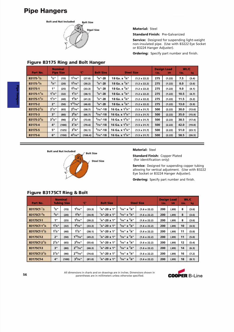
7/18/2019 PH Pipe Hanger Catalog
http://slidepdf.com/reader/full/ph-pipe-hanger-catalog 58/224
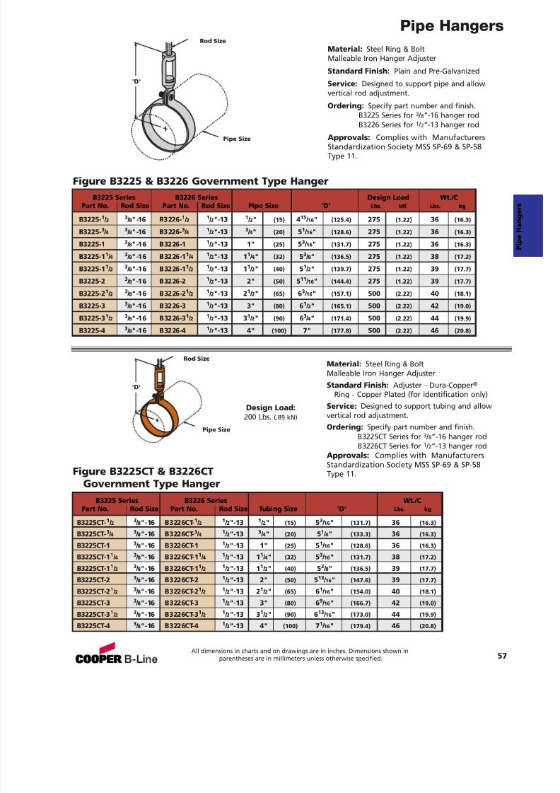
7/18/2019 PH Pipe Hanger Catalog
http://slidepdf.com/reader/full/ph-pipe-hanger-catalog 59/224
Pipe Hangers
57All dimensions in charts and on drawings are in inches. Dimensions shown in
parentheses are in millimeters unless otherwise specified.
Material: Steel Ring & BoltMalleable Iron Hanger Adjuster
Standard Finish: Plain and Pre-Galvanized
Service: Designed to support pipe and allowvertical rod adjustment.
Ordering: Specify part number and finish.B3225 Series for 3 / 8”-16 hanger rodB3226 Series for 1 / 2”-13 hanger rod
Approvals: Complies with ManufacturersStandardization Society MSS SP-69 & SP-58Type 11.
Figure B3225 & B3226 Government Type Hanger
'D'
Pipe Size
Rod Size
B3225 Series B3226 Series Design Load Wt./CPart No. Rod Size Part No. Rod Size Pipe Size 'D' Lbs. kN Lbs. kg
B3225- 1 / 2 3 / 8"-16 B3226- 1 / 2 1 / 2"-13 1 / 2" (15) 415 / 16 " (125.4) 275 (1.22) 36 (16.3)
B3225- 3 / 4 3 / 8"-16 B3226- 3 / 4 1 / 2"-13 3 / 4" (20) 51 / 16 " (128.6) 275 (1.22) 36 (16.3)
B3225-1 3 / 8"-16 B3226-1 1 / 2"-13 1" (25) 53 / 16 " (131.7) 275 (1.22) 36 (16.3)
B3225-1 1 / 4 3 / 8"-16 B3226-1 1 / 4 1 / 2"-13 1 1 / 4" (32) 53 / 8" (136.5) 275 (1.22) 38 (17.2)
B3225-1 1 / 2 3 / 8"-16 B3226-1 1 / 2 1 / 2"-13 1 1 / 2" (40) 51 / 2" (139.7) 275 (1.22) 39 (17.7)
B3225-2 3 / 8"-16 B3226-2 1 / 2"-13 2" (50) 511 / 16 " (144.4) 275 (1.22) 39 (17.7)
B3225-2 1 / 2 3 / 8"-16 B3226-2 1 / 2 1 / 2"-13 2 1 / 2" (65) 63 / 16 " (157.1) 500 (2.22) 40 (18.1)
B3225-3 3 / 8"-16 B3226-3 1 / 2"-13 3" (80) 61 / 2" (165.1) 500 (2.22) 42 (19.0)
B3225-3 1 / 2 3 / 8"-16 B3226-3 1 / 2 1 / 2"-13 3 1 / 2" (90) 63 / 4" (171.4) 500 (2.22) 44 (19.9)
B3225-4 3 / 8"-16 B3226-4 1 / 2"-13 4" (100) 7" (177.8) 500 (2.22) 46 (20.8)
Material: Steel Ring & BoltMalleable Iron Hanger AdjusterStandard Finish: Adjuster - Dura-Copper ®
Ring - Copper Plated (for identification only)Service: Designed to support tubing and allowvertical rod adjustment.Ordering: Specify part number and finish.
B3225CT Series for 3 / 8”-16 hanger rodB3226CT Series for 1 / 2”-13 hanger rod
Approvals: Complies with ManufacturersStandardization Society MSS SP-69 & SP-58Type 11.Figure B3225CT & B3226CT
Government Type HangerB3225 Series B3226 Series Wt./C
Part No. Rod Size Part No. Rod Size Tubing Size 'D' Lbs. kg
B3225CT-1 / 2
3 / 8"-16 B3226CT-
1 / 2
1 / 2"-13
1 / 2" (15) 5
3 / 16 " (131.7) 36 (16.3)
B3225CT- 3 / 4 3 / 8"-16 B3226CT- 3 / 4 1 / 2"-13 3 / 4" (20) 51 / 4" (133.3) 36 (16.3)
B3225CT-1 3 / 8"-16 B3226CT-1 1 / 2"-13 1" (25) 51 / 16 " (128.6) 36 (16.3)
B3225CT-1 1 / 4 3 / 8"-16 B3226CT-1 1 / 4 1 / 2"-13 1 1 / 4" (32) 53 / 16 " (131.7) 38 (17.2)
B3225CT-1 1 / 2 3 / 8"-16 B3226CT-1 1 / 2 1 / 2"-13 1 1 / 2" (40) 53 / 8" (136.5) 39 (17.7)
B3225CT-2 3 / 8"-16 B3226CT-2 1 / 2"-13 2" (50) 513 / 16 " (147.6) 39 (17.7)
B3225CT-2 1 / 2 3 / 8"-16 B3226CT-2 1 / 2 1 / 2"-13 2 1 / 2" (65) 61 / 16 " (154.0) 40 (18.1)
B3225CT-3 3 / 8"-16 B3226CT-3 1 / 2"-13 3" (80) 69 / 16 " (166.7) 42 (19.0)
B3225CT-3 1 / 2 3 / 8"-16 B3226CT-3 1 / 2 1 / 2"-13 3 1 / 2" (90) 613 / 16 " (173.0) 44 (19.9)
B3225CT-4 3 / 8"-16 B3226CT-4 1 / 2"-13 4" (100) 71 / 16 " (179.4) 46 (20.8)
'D'
Pipe Size
Rod Size
Design Load:200 Lbs. (.89 kN)
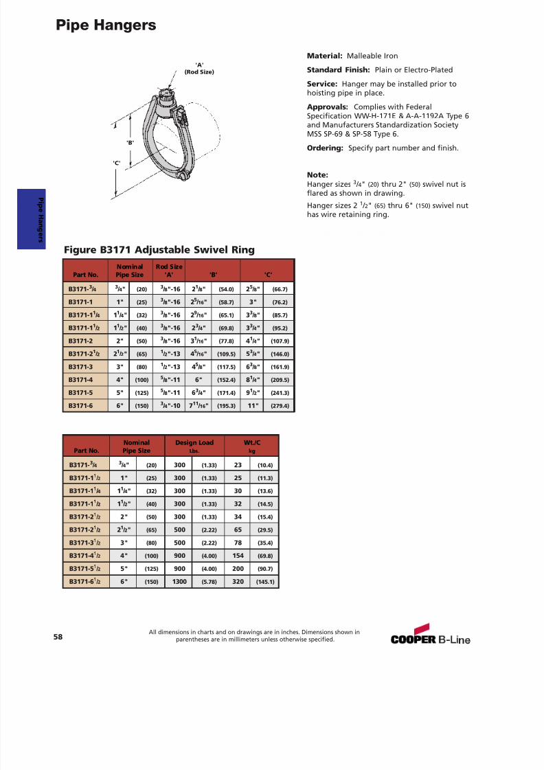
7/18/2019 PH Pipe Hanger Catalog
http://slidepdf.com/reader/full/ph-pipe-hanger-catalog 60/224
Pipe Hangers
58All dimensions in charts and on drawings are in inches. Dimensions shown in
parentheses are in millimeters unless otherwise specified.
Material: Malleable Iron
Standard Finish: Plain or Electro-Plated
Service: Hanger may be installed prior tohoisting pipe in place.
Approvals: Complies with FederalSpecification WW-H-171E & A-A-1192A Type 6
and Manufacturers Standardization SocietyMSS SP-69 & SP-58 Type 6.
Ordering: Specify part number and finish.
Note:Hanger sizes 3 / 4" (20) thru 2" (50) swivel nut isflared as shown in drawing.
Hanger sizes 2 1 / 2" (65) thru 6" (150) swivel nuthas wire retaining ring.
Figure B3171 Adjustable Swivel Ring
'B'
'A'(Rod Size)
'C'
Nominal Rod SizePart No. Pipe Size 'A' 'B' 'C'
B3171- 3 / 4 3 / 4" (20) 3 / 8"-16 2 1 / 8" (54.0) 25 / 8" (66.7)
B3171-1 1" (25) 3 / 8"-16 2 5 / 16" (58.7) 3" (76.2)
B3171-1 1 / 4 11 / 4" (32) 3 / 8"-16 2 9 / 16" (65.1) 33 / 8" (85.7)
B3171-1 1 / 2 11 / 2" (40) 3 / 8"-16 2 3 / 4" (69.8) 33 / 4" (95.2)
B3171-2 2" (50) 3 / 8"-16 3 1 / 16" (77.8) 41 / 4" (107.9)
B3171-2 1 / 2 21 / 2" (65) 1 / 2"-13 4 5 / 16" (109.5) 53 / 4" (146.0)
B3171-3 3" (80) 1 / 2"-13 4 5 / 8" (117.5) 63 / 8" (161.9)
B3171-4 4" (100)5
/ 8"-11 6" (152.4) 81
/ 4" (209.5)B3171-5 5" (125) 5 / 8"-11 6 3 / 4" (171.4) 91 / 2" (241.3)
B3171-6 6" (150) 3 / 4"-10 7 11 / 16" (195.3) 11" (279.4)
Nominal Design Load Wt./CPart No. Pipe Size Lbs. kg
B3171- 3 / 4 3 / 4" (20) 300 (1.33) 23 (10.4)
B3171-1 1 / 2 1" (25) 300 (1.33) 25 (11.3)
B3171-1 1 / 4 11 / 4" (32) 300 (1.33) 30 (13.6)
B3171-1 1 / 2 11 / 2" (40) 300 (1.33) 32 (14.5)
B3171-2 1 / 2 2" (50) 300 (1.33) 34 (15.4)
B3171-2 1 / 2 21 / 2" (65) 500 (2.22) 65 (29.5)
B3171-3 1 / 2 3" (80) 500 (2.22) 78 (35.4)
B3171-4 1 / 2 4" (100) 900 (4.00) 154 (69.8)
B3171-5 1 / 2 5" (125) 900 (4.00) 200 (90.7)
B3171-6 1 / 2 6" (150) 1300 (5.78) 320 (145.1)
P i peHanger s
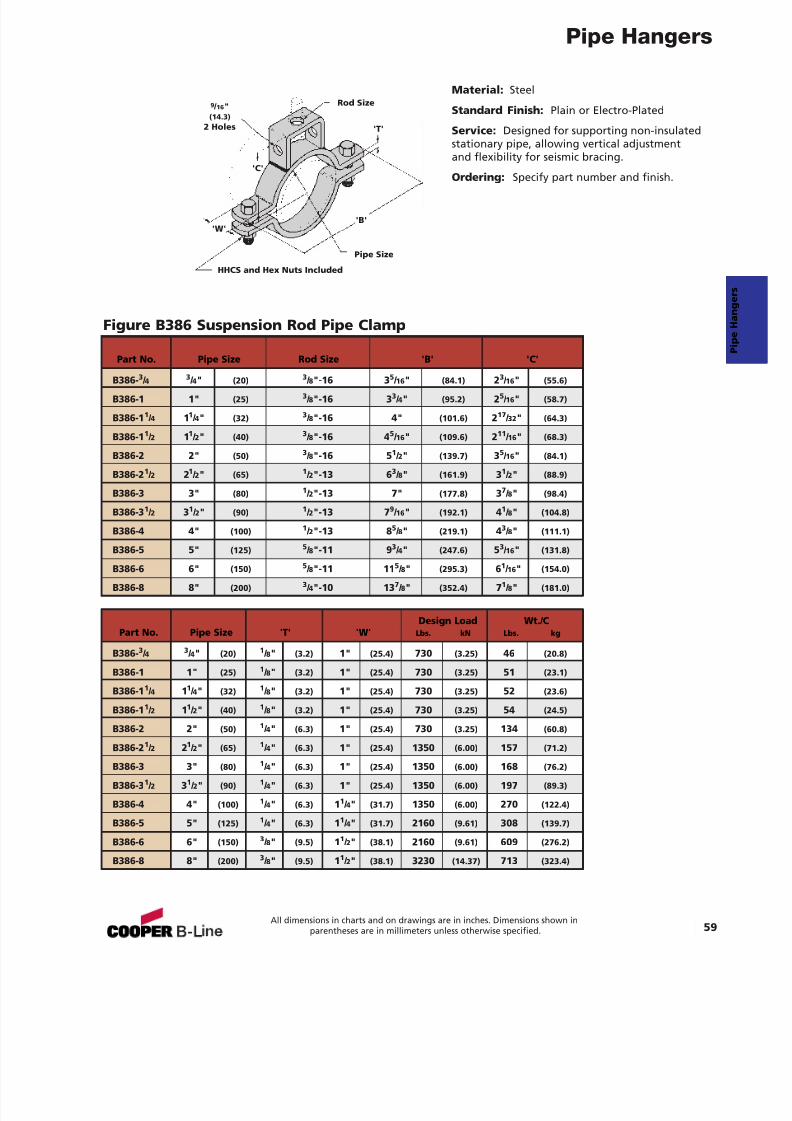
7/18/2019 PH Pipe Hanger Catalog
http://slidepdf.com/reader/full/ph-pipe-hanger-catalog 61/224
Pipe Hangers
59All dimensions in charts and on drawings are in inches. Dimensions shown in
parentheses are in millimeters unless otherwise specified.
Material: Steel
Standard Finish: Plain or Electro-Plated
Service: Designed for supporting non-insulatedstationary pipe, allowing vertical adjustmentand flexibility for seismic bracing.
Ordering: Specify part number and finish.
Figure B386 Suspension Rod Pipe Clamp
HHCS and Hex Nuts Included
Pipe Size
Rod Size
'T'
9 / 16 "(14.3)
2 Holes
'B''W'
'C'
Design Load Wt./CPart No. Pipe Size 'T' 'W' Lbs. kN Lbs. kg
B386- 3 / 4 3 / 4" (20) 1 / 8" (3.2) 1" (25.4) 730 (3.25) 46 (20.8)
B386-1 1" (25) 1 / 8" (3.2) 1" (25.4) 730 (3.25) 51 (23.1)
B386-1 1 / 4 11 / 4" (32) 1 / 8" (3.2) 1" (25.4) 730 (3.25) 52 (23.6)
B386-1 1 / 2 11 / 2" (40) 1 / 8" (3.2) 1" (25.4) 730 (3.25) 54 (24.5)
B386-2 2" (50) 1 / 4" (6.3) 1" (25.4) 730 (3.25) 134 (60.8)
B386-2 1 / 2 21 / 2" (65) 1 / 4" (6.3) 1" (25.4) 1350 (6.00) 157 (71.2)
B386-3 3" (80) 1 / 4" (6.3) 1" (25.4) 1350 (6.00) 168 (76.2)
B386-3 1 / 2 31 / 2" (90) 1 / 4" (6.3) 1" (25.4) 1350 (6.00) 197 (89.3)
B386-4 4" (100) 1 / 4" (6.3) 11 / 4" (31.7) 1350 (6.00) 270 (122.4)
B386-5 5" (125) 1 / 4" (6.3) 11 / 4" (31.7) 2160 (9.61) 308 (139.7)
B386-6 6" (150) 3 / 8" (9.5) 11 / 2" (38.1) 2160 (9.61) 609 (276.2)
B386-8 8" (200) 3 / 8" (9.5) 11 / 2" (38.1) 3230 (14.37) 713 (323.4)
Part No. Pipe Size Rod Size 'B' 'C'
B386- 3 / 4 3 / 4" (20) 3 / 8"-16 3 5 / 16 " (84.1) 23 / 16 " (55.6)
B386-1 1" (25) 3 / 8"-16 3 3 / 4" (95.2) 25 / 16 " (58.7)
B386-1 1 / 4 11 / 4" (32) 3 / 8"-16 4" (101.6) 217 / 32 " (64.3)
B386-1 1 / 2 11 / 2" (40) 3 / 8"-16 4 5 / 16 " (109.6) 211 / 16 " (68.3)
B386-2 2" (50) 3 / 8"-16 5 1 / 2" (139.7) 35 / 16 " (84.1)
B386-2 1 / 2 21 / 2" (65) 1 / 2"-13 6 3 / 8" (161.9) 31 / 2" (88.9)
B386-3 3" (80) 1 / 2"-13 7" (177.8) 37 / 8" (98.4)
B386-3 1 / 2 31 / 2" (90) 1 / 2"-13 7 9 / 16 " (192.1) 41 / 8" (104.8)
B386-4 4" (100) 1 / 2"-13 8 5 / 8" (219.1) 43 / 8" (111.1)
B386-5 5" (125) 5 / 8"-11 9 3 / 4" (247.6) 53 / 16 " (131.8)
B386-6 6" (150) 5 / 8"-11 11 5 / 8" (295.3) 61 / 16 " (154.0)
B386-8 8" (200) 3 / 4"-10 13 7 / 8" (352.4) 71 / 8" (181.0)
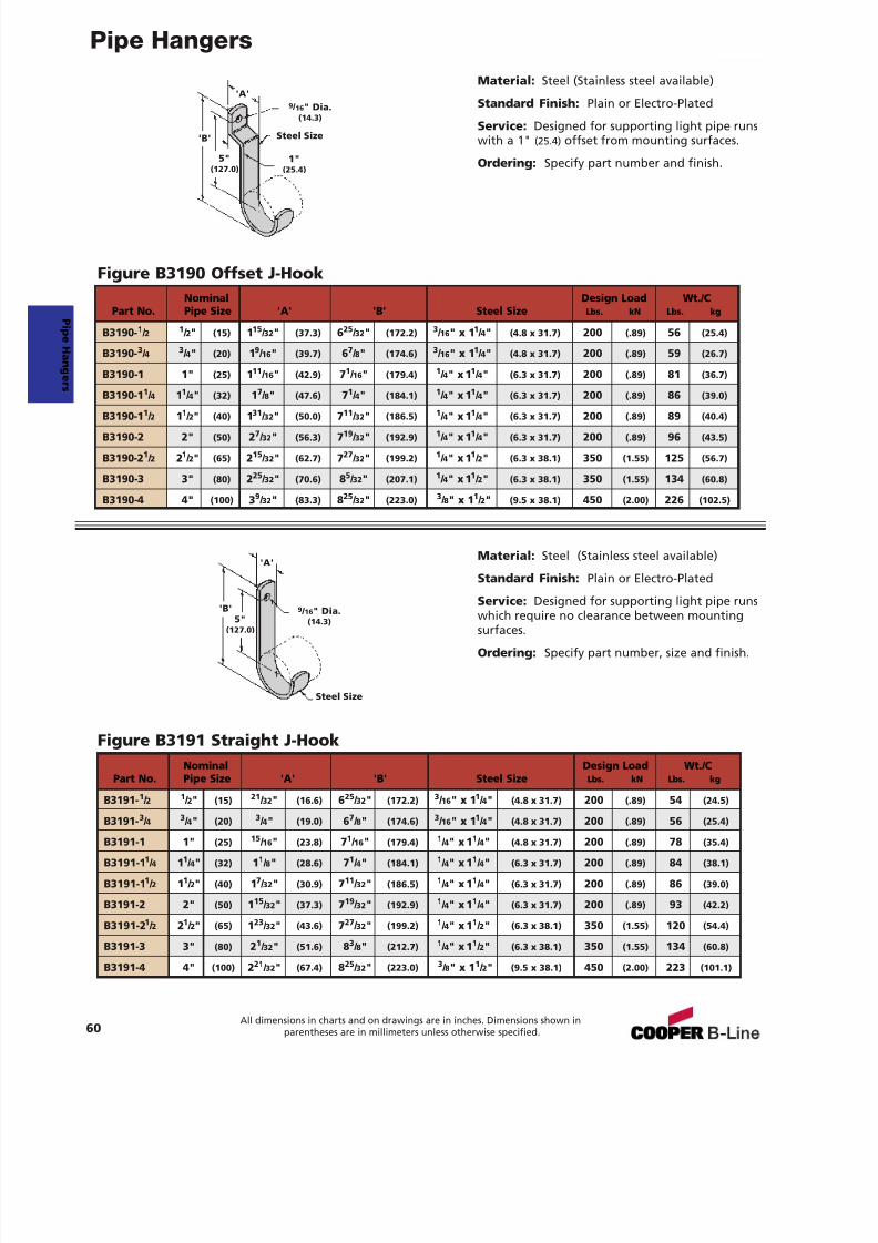
7/18/2019 PH Pipe Hanger Catalog
http://slidepdf.com/reader/full/ph-pipe-hanger-catalog 62/224
Pipe Hangers
60All dimensions in charts and on drawings are in inches. Dimensions shown in
parentheses are in millimeters unless otherwise specified.
Material: Steel (Stainless steel available)
Standard Finish: Plain or Electro-Plated
Service: Designed for supporting light pipe runswith a 1" (25.4) offset from mounting surfaces.
Ordering: Specify part number and finish.
Figure B3190 Offset J-Hook
Material: Steel (Stainless steel available)
Standard Finish: Plain or Electro-Plated
Service: Designed for supporting light pipe runs
which require no clearance between mountingsurfaces.
Ordering: Specify part number, size and finish.
Figure B3191 Straight J-Hook
'B' Steel Size
9 / 16 " Dia.(14.3)
5"(127.0)
1"(25.4)
'A'
'B'
Steel Size
9 / 16 " Dia.(14.3)5"
(127.0)
'A'
Nominal Design Load Wt./CPart No. Pipe Size 'A' 'B' Steel Size Lbs. kN Lbs. kg
B3190- 1 / 2 1 / 2" (15) 115 / 32 " (37.3) 625 / 32 " (172.2) 3 / 16 " x 1 1 / 4" (4.8 x 31.7) 200 (.89) 56 (25.4)
B3190- 3 / 4 3 / 4" (20) 19 / 16 " (39.7) 67 / 8" (174.6) 3 / 16 " x 1 1 / 4" (4.8 x 31.7) 200 (.89) 59 (26.7)
B3190-1 1" (25) 111 / 16 " (42.9) 71 / 16 " (179.4) 1 / 4" x 1 1 / 4" (6.3 x 31.7) 200 (.89) 81 (36.7)
B3190-1 1 / 4 11 / 4" (32) 17 / 8" (47.6) 71 / 4" (184.1) 1 / 4" x 1 1 / 4" (6.3 x 31.7) 200 (.89) 86 (39.0)
B3190-1 1 / 2 11 / 2" (40) 131 / 32 " (50.0) 711 / 32 " (186.5) 1 / 4" x 1 1 / 4" (6.3 x 31.7) 200 (.89) 89 (40.4)
B3190-2 2" (50) 27 / 32 " (56.3) 719 / 32 " (192.9) 1 / 4" x 1 1 / 4" (6.3 x 31.7) 200 (.89) 96 (43.5)
B3190-2 1 / 2 21 / 2" (65) 215 / 32 " (62.7) 727 / 32 " (199.2) 1 / 4" x 1 1 / 2" (6.3 x 38.1) 350 (1.55) 125 (56.7)
B3190-3 3" (80) 225 / 32 " (70.6) 85 / 32 " (207.1) 1 / 4" x 1 1 / 2" (6.3 x 38.1) 350 (1.55) 134 (60.8)
B3190-4 4" (100) 39 / 32 " (83.3) 825 / 32 " (223.0) 3 / 8" x 1 1 / 2" (9.5 x 38.1) 450 (2.00) 226 (102.5)
Nominal Design Load Wt./CPart No. Pipe Size 'A' 'B' Steel Size Lbs. kN Lbs. kg
B3191- 1 / 2 1 / 2" (15) 21 / 32 " (16.6) 625 / 32 " (172.2) 3 / 16 " x 1 1 / 4" (4.8 x 31.7) 200 (.89) 54 (24.5)
B3191-3 / 4
3 / 4" (20)
3 / 4" (19.0) 6
7 / 8" (174.6)
3 / 16 " x 1
1 / 4" (4.8 x 31.7) 200 (.89) 56 (25.4)
B3191-1 1" (25) 15 / 16 " (23.8) 71 / 16 " (179.4) 1 / 4" x 1 1 / 4" (4.8 x 31.7) 200 (.89) 78 (35.4)
B3191-1 1 / 4 11 / 4" (32) 11 / 8" (28.6) 71 / 4" (184.1) 1 / 4" x 1 1 / 4" (6.3 x 31.7) 200 (.89) 84 (38.1)
B3191-1 1 / 2 11 / 2" (40) 17 / 32 " (30.9) 711 / 32 " (186.5) 1 / 4" x 1 1 / 4" (6.3 x 31.7) 200 (.89) 86 (39.0)
B3191-2 2" (50) 115 / 32 " (37.3) 719 / 32 " (192.9) 1 / 4" x 1 1 / 4" (6.3 x 31.7) 200 (.89) 93 (42.2)
B3191-2 1 / 2 21 / 2" (65) 123 / 32 " (43.6) 727 / 32 " (199.2) 1 / 4" x 1 1 / 2" (6.3 x 38.1) 350 (1.55) 120 (54.4)
B3191-3 3" (80) 21 / 32 " (51.6) 83 / 8" (212.7) 1 / 4" x 1 1 / 2" (6.3 x 38.1) 350 (1.55) 134 (60.8)
B3191-4 4" (100) 221 / 32 " (67.4) 825 / 32 " (223.0) 3 / 8" x 1 1 / 2" (9.5 x 38.1) 450 (2.00) 223 (101.1)
P i peHanger s
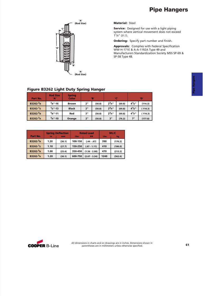
7/18/2019 PH Pipe Hanger Catalog
http://slidepdf.com/reader/full/ph-pipe-hanger-catalog 63/224
Pipe Hangers
61All dimensions in charts and on drawings are in inches. Dimensions shown in
parentheses are in millimeters unless otherwise specified.
Material: Steel
Service: Designed for use with a light pipingsystem where vertical movement does not exceed11 / 4" (31.7) .
Ordering: Specify part number and finish.
Approvals: Complies with Federal SpecificationWW-H-171E & A-A-1192A Type 49 andManufacturers Standardization Society MSS SP-69 &SP-58 Type 48.
Figure B3262 Light Duty Spring Hanger
'B'
'C'
'D'
'A'(Rod Size)
'A'(Rod Size)
Spring Deflection Rated Load Wt./CPart No. In mm Lbs. kN Lbs. kg
B3262- 3 / 8 1.20 (30.1) 100-150 (.44 - .67) 390 (176.2)
B3262-1 / 2 1.10 (27.7) 150-250 (.67 - 1.11) 410 (186.0)
B3262- 5 / 8 1.00 (25.4) 350-450 (1.56 - 2.00) 470 (213.2)
B3262- 3 / 4 1.20 (30.1) 600-750 (2.67 - 3.34) 1240 (562.6)
Rod Size SpringPart No. 'A' Color ‘B’ 'C' 'D'
B3262- 3 / 8 3 / 8"-16 Brown 2" (50.8) 23 / 4" (69.8) 41 / 2" (114.3)
B3262- 1 / 2 1 / 2"-13 Black 2" (50.8) 23 / 4" (69.8) 41 / 2" ( 114.3)
B3262- 5 / 8 5 / 8"-11 Red 2" (50.8) 23 / 4" (69.8) 41 / 2" ( 114.3)
B3262- 3 / 4 3 / 4"-10 Orange 2" (50.8) 3" (76.2) 7" (177.8)
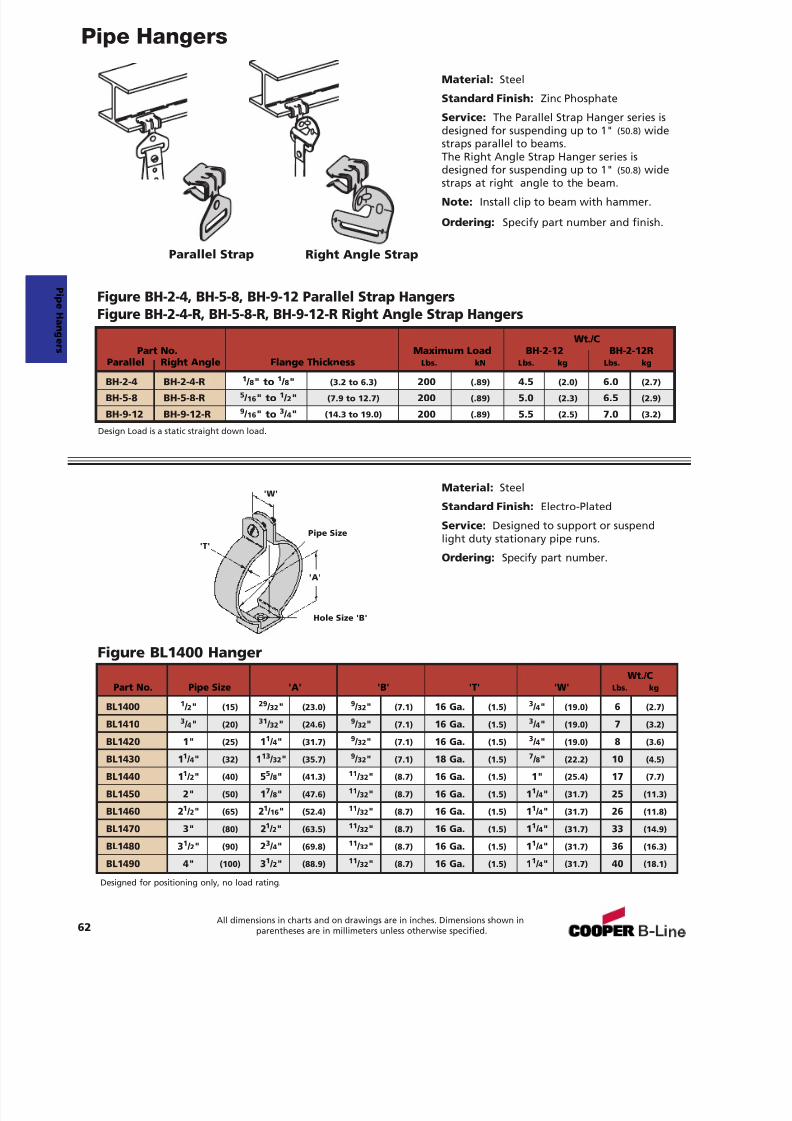
7/18/2019 PH Pipe Hanger Catalog
http://slidepdf.com/reader/full/ph-pipe-hanger-catalog 64/224
7/18/2019 PH Pipe Hanger Catalog
http://slidepdf.com/reader/full/ph-pipe-hanger-catalog 65/224
Pipe Hangers
63All dimensions in charts and on drawings are in inches. Dimensions shown in
parentheses are in millimeters unless otherwise specified.
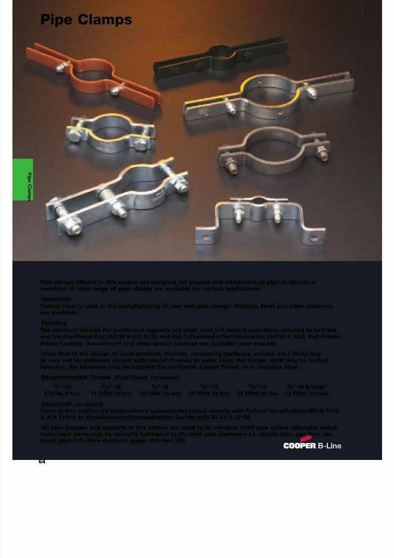
7/18/2019 PH Pipe Hanger Catalog
http://slidepdf.com/reader/full/ph-pipe-hanger-catalog 66/224
Pipe clamps offered in this section are designed for support and attachment of pipe to structuralmembers. A wide range of pipe clamps are available for various applications.
MaterialsCarbon Steel is used in the manufacturing of riser and pipe clamps. Stainless Steel and other materialsare available.
FinishesThe standard finishes for mechanical supports are plain steel (oil coated) sometimes referred to as blackand Electro-Plated Zinc (ASTM B 633 SC3). Hot-Dip Galvanized After Fabrication (ASTM A 123), Red Primer,Plastic Coating, Dura-Green ® and other special coatings are available upon request.
Note: Due to the design of some products, (threads, connecting hardware, swivels, etc.) items mayor may not be uniformly coated with special finishes. In some cases, the hanger itself may be coated,
however, the hardware may be supplied Electro-Plated, Copper Plated, or in Stainless Steel.Recommended Torque (Pipe Clamp Hardware)
1 / 4”-20 5 / 16 ”-18 3 / 8”-16 1 / 2”-13 5 / 8”-11 3 / 4”-10 & larger6 ft/lbs (8 Nm) 11 ft/lbs (19 Nm) 19 ft/lbs (26 Nm) 50 ft/lbs (68 Nm) 65 ft/lbs (88 Nm) 75 ft/lbs (101 Nm)
Approvals (as noted)Items in this section are Underwriters' Laboratories Listed, comply with Federal Specification WW-H-171E& A-A-1192A or Manufacturers Standardization Society MSS SP-69 & SP-58.
All pipe hangers and supports in this section are sized to fit schedule 40/80 pipe unless otherwise noted.Some steel items may be specially fabricated to fit other pipe diameters i.e. ductile iron, cast iron, etc.Select pipe O.D. from charts on pages 201 thru 206.
Pipe Clamps
P i peC l amps
64
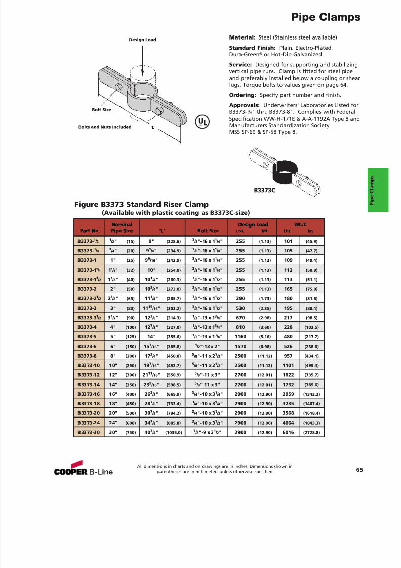
7/18/2019 PH Pipe Hanger Catalog
http://slidepdf.com/reader/full/ph-pipe-hanger-catalog 67/224
Pipe Clamps
Material: Steel (Stainless steel available)
Standard Finish: Plain, Electro-Plated,Dura-Green ® or Hot-Dip Galvanized
Service: Designed for supporting and stabilizingvertical pipe runs. Clamp is fitted for steel pipeand preferably installed below a coupling or shearlugs. Torque bolts to values given on page 64.
Ordering: Specify part number and finish.
Approvals: Underwriters' Laboratories Listed forB3373- 3 / 4" thru B3373-8". Complies with FederalSpecification WW-H-171E & A-A-1192A Type 8 andManufacturers Standardization SocietyMSS SP-69 & SP-58 Type 8.
Figure B3373 Standard Riser Clamp(Available with plastic coating as B3373C-size)
Bolts and Nuts Included
Design Load
Bolt Size
'L'
Nominal Design Load Wt./CPart No. Pipe Size 'L' Bolt Size Lbs. kN Lbs. kg
B3373- 1 / 2 1 / 2" (15) 9" (228.6) 3 / 8"-16 x 1 1 / 4" 255 (1.13) 101 (45.9)
B3373- 3 / 4 3 / 4" (20) 91 / 4" (234.9) 3 / 8"-16 x 1 1 / 4" 255 (1.13) 105 (47.7)
B3373-1 1" (25) 99 / 16 " (242.9) 3 / 8"-16 x 1 1 / 4" 255 (1.13) 109 (49.4)
B3373-1 1 / 4 11 / 4" (32) 10" (254.0) 3 / 8"-16 x 1 1 / 4" 255 (1.13) 112 (50.9)
B3373-11
/ 2
11
/ 2" (40) 10
1
/ 4" (260.3)
3
/ 8"-16 x 1
1
/ 2" 255 (1.13) 113 (51.1)
B3373-2 2" (50) 10 3 / 4" (273.0) 3 / 8"-16 x 1 1 / 2" 255 (1.13) 165 (75.0)
B3373-2 1 / 2 21 / 2" (65) 11 1 / 4" (285.7) 3 / 8"-16 x 1 1 / 2" 390 (1.73) 180 (81.6)
B3373-3 3" (80) 11 15 / 16 " (303.2) 3 / 8"-16 x 1 1 / 2" 530 (2.35) 195 (88.4)
B3373-3 1 / 2 31 / 2" (90) 12 3 / 8" (314.3) 1 / 2"-13 x 1 3 / 4" 670 (2.98) 217 (98.5)
B3373-4 4" (100) 12 7 / 8" (327.0) 1 / 2"-13 x 1 3 / 4" 810 (3.60) 228 (103.5)
B3373-5 5" (125) 14" (355.6) 1 / 2"-13 x 1 3 / 4" 1160 (5.16) 480 (217.7)
B3373-6 6" (150) 15 3 / 16" (385.8) 1 / 2"-13 x 2" 1570 (6.98) 526 (238.6)
B3373-8 8" (200) 17 3 / 4" (450.8) 5 / 8"-11 x 2 1 / 2" 2500 (11.12) 957 (434.1)
B3373-10 10" (250) 19 7 / 16" (493.7) 5 / 8"-11 x 2 1 / 2" 2500 (11.12) 1101 (499.4)
B3373-12 12" (300) 2111
/ 16 " (550.9)5 / 8"-11 x 3" 2700 (12.01) 1622 (735.7)
B3373-14 14" (350) 23 9 / 16" (598.5) 5 / 8"-11 x 3" 2700 (12.01) 1732 (785.6)
B3373-16 16" (400) 26 3 / 8" (669.9) 3 / 4"-10 x 3 1 / 4" 2900 (12.90) 2959 (1342.2)
B3373-18 18" (450) 28 7 / 8" (733.4) 3 / 4"-10 x 3 1 / 4" 2900 (12.90) 3235 (1467.4)
B3373-20 20" (500) 30 7 / 8" (784.2) 3 / 4"-10 x 3 1 / 2" 2900 (12.90) 3568 (1618.4)
B3373-24 24" (600) 34 7 / 8" (885.8) 3 / 4"-10 x 3 1 / 2" 2900 (12.90) 4064 (1843.3)
B3373-30 30" (750) 40 3 / 4" (1035.0) 7 / 8"-9 x 3 1 / 2" 2900 (12.90) 6016 (2728.8)
65All dimensions in charts and on drawings are in inches. Dimensions shown in
parentheses are in millimeters unless otherwise specified.
B3373C
UL®
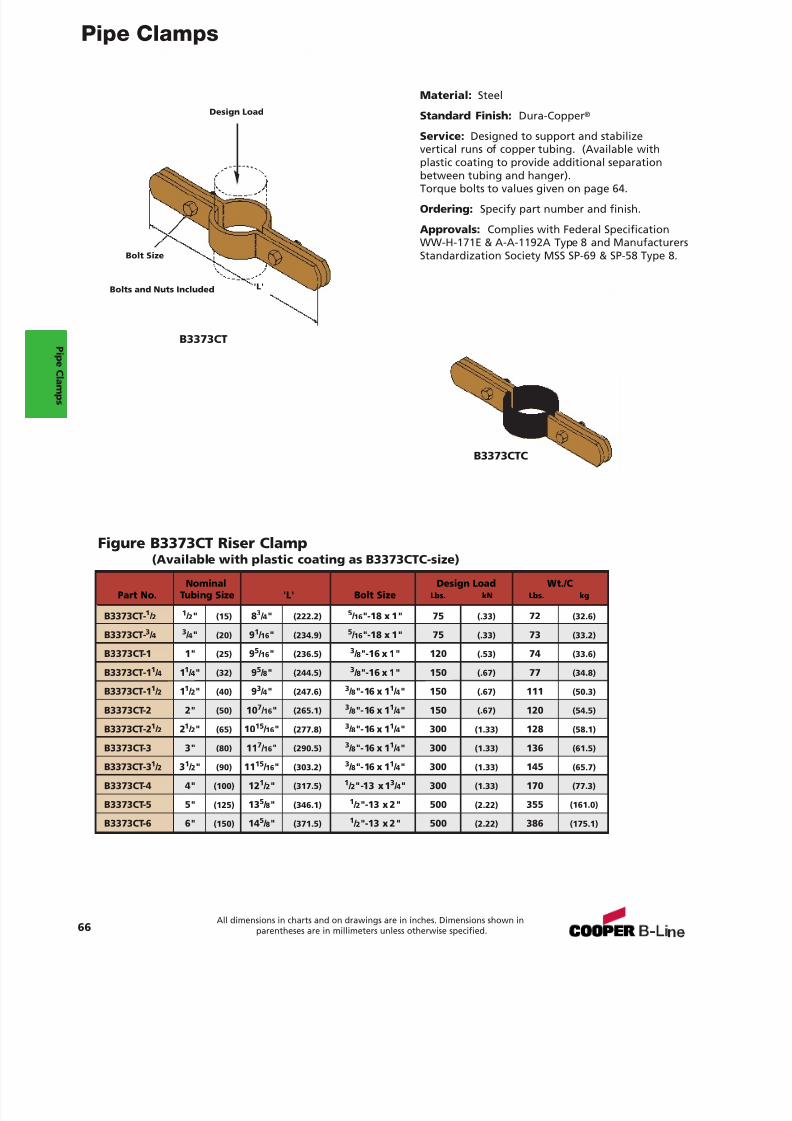
7/18/2019 PH Pipe Hanger Catalog
http://slidepdf.com/reader/full/ph-pipe-hanger-catalog 68/224
Pipe Clamps
66All dimensions in charts and on drawings are in inches. Dimensions shown in
parentheses are in millimeters unless otherwise specified.
Material: Steel
Standard Finish: Dura-Copper ®
Service: Designed to support and stabilizevertical runs of copper tubing. (Available withplastic coating to provide additional separationbetween tubing and hanger).Torque bolts to values given on page 64.
Ordering: Specify part number and finish.
Approvals: Complies with Federal SpecificationWW-H-171E & A-A-1192A Type 8 and ManufacturersStandardization Society MSS SP-69 & SP-58 Type 8.
Figure B3373CT Riser Clamp(Available with plastic coating as B3373CTC-size)
B3373CT
B3373CTC
Bolts and Nuts Included
Bolt Size
'L'
Nominal Design Load Wt./CPart No. Tubing Size 'L' Bolt Size Lbs. kN Lbs. kg
B3373CT- 1 / 2 1 / 2" (15) 83 / 4" (222.2) 5 / 16 "-18 x 1" 75 (.33) 72 (32.6)
B3373CT- 3 / 4 3 / 4" (20) 91 / 16 " (234.9) 5 / 16 "-18 x 1" 75 (.33) 73 (33.2)
B3373CT-1 1" (25) 95 / 16 " (236.5) 3 / 8"-16 x 1" 120 (.53) 74 (33.6)
B3373CT-1 1 / 4 11 / 4" (32) 95 / 8" (244.5) 3 / 8"-16 x 1" 150 (.67) 77 (34.8)
B3373CT-1 1 / 2 11 / 2" (40) 93 / 4" (247.6) 3 / 8"-16 x 1 1 / 4" 150 (.67) 111 (50.3)
B3373CT-2 2" (50) 10 7 / 16 " (265.1) 3 / 8"-16 x 1 1 / 4" 150 (.67) 120 (54.5)
B3373CT-2 1 / 2 21 / 2" (65) 10 15 / 16 " (277.8) 3 / 8"-16 x 1 1 / 4" 300 (1.33) 128 (58.1)
B3373CT-3 3" (80) 11 7 / 16 " (290.5) 3 / 8"-16 x 1 1 / 4" 300 (1.33) 136 (61.5)
B3373CT-3 1 / 2 31 / 2" (90) 11 15 / 16 " (303.2) 3 / 8"-16 x 1 1 / 4" 300 (1.33) 145 (65.7)
B3373CT-4 4" (100) 12 1 / 2" (317.5) 1 / 2"-13 x1 3 / 4" 300 (1.33) 170 (77.3)
B3373CT-5 5" (125) 13 5 / 8" (346.1) 1 / 2"-13 x 2" 500 (2.22) 355 (161.0)
B3373CT-6 6" (150) 14 5 / 8" (371.5) 1 / 2"-13 x 2" 500 (2.22) 386 (175.1)
Design Load
P i peC l amps
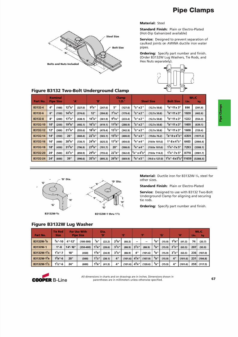
7/18/2019 PH Pipe Hanger Catalog
http://slidepdf.com/reader/full/ph-pipe-hanger-catalog 69/224
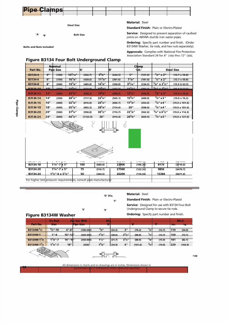
7/18/2019 PH Pipe Hanger Catalog
http://slidepdf.com/reader/full/ph-pipe-hanger-catalog 70/224
Pipe Clamps
68All dimensions in charts and on drawings are in inches. Dimensions shown in
parentheses are in millimeters unless otherwise specified.
Material: Steel
Standard Finish: Plain or Electro-Plated
Service: Designed to prevent separation of caulked joints on AWWA ductile iron water pipes.
Ordering: Specify part number and finish. (OrderB3134W Washer, tie rods, and hex nuts separately).
Approvals: Complies with National Fire ProtectionAssociation Standard 24 for 4" (100) thru 12" (300).Figure B3134 Four Bolt Underground Clamp
Material: Steel
Standard Finish: Plain or Electro-Plated
Service: Designed for use with B3134 Four-BoltUnderground Clamp to secure tie rods.
Ordering: Specify part number and finish.Figure B3134W Washer
Bolts and Nuts Included
Steel Size
Bolt Size'A'
'D' Dia.
'F'
'E''E'
'B'
For higher test pressure requirements, consult pipe manufacturer.
Nominal ClampPart No. Pipe Size 'A' 'B' 'I.D.' Steel Size
B3134-4 4" (100) 14 7 / 16 " (366.7) 95 / 8" (244.5) 5" (127.0) 1 / 2" x 2" (12.7 x 50.8)
B3134-6 6" (150) 16 7 / 8" (428.6) 11 7 / 8" (301.6) 71 / 8" (181.0) 1 / 2" x 2" (12.7 x 50.8)
B3134-8 8" (200) 19 1 / 8" (485.8) 141 / 8" (358.8) 95 / 16 " (236.5) 5 / 8" x 2 1 / 2" (15.9 X 63.5)
B3134-10 10" (250) 21 3 / 8" (542.9) 165 / 8" (422.3) 11 1 / 2" (292.1) 5 / 8" x 2 1 / 2" (15.9 X 63.5)
B3134-12 12" (300) 25 1 / 8" (638.2) 195 / 8" (498.5) 13 1 / 2" (342.9) 5 / 8" x 3" (15.9 x 76.2)
B3134-14 14" (350) 28 1 / 4" (717.5) 221 / 4" (565.1) 15 3 / 4" (400.0) 3 / 4"x 3 " (19.0 x 76.2)
B3134-16 16" (400) 32 1 / 8" (816.0) 261 / 4" (666.7) 17 7 / 8" (454.0) 3 / 4"x 4 " (19.0 x 101.6)
B3134-18 18" (450) 35 1 / 8" (892.2) 281 / 8" (714.4) 20" (508.0) 3 / 4"x 4 " (19.0 x 101.6)
B3134-20 20" (500) 37 3 / 4" (958.8) 30 1 / 2" (774.7) 22 1 / 8" (562.0) 3 / 4" x 4 1 / 2" (19.0 x 114.3)
B3134-24 24" (600) 44 1 / 4" (1123.9) 36" (914.4) 26 3 / 8" (669.9) 3 / 4"x 5 " (19.0 x 127.0)
Maximum Test Pressure Force On Clamp Wt./CPart No. Bolt Size psi Pa Lbs. kN Lbs. kg
B3134-4 5 / 8"-11 x 3" 250 (1722.5) 4550 (20.24) 1012 (459.0)
B3134-6 5 / 8"-11 x 3" 250 (1722.5) 9340 (41.54) 1204 (546.1)
B3134-8 5 / 8"-11 x 3 1 / 2" 250 (1722.5) 16080 (71.52) 2091 (948.5)
B3134-10 3 / 4"-10 x 4" 250 (1722.5) 24180 (107.55) 2466 (1118.6)
B3134-12 7 / 8"-9 x 4" 250 (1722.5) 34230 (152.25) 3537 (1604.4)
B3134-14 7 / 8"-9 x 4 1 / 2" 120 (826.8) 22200 (98.74) 4718 (2140.1)
B3134-16 1"-8 x 4 1 / 2" 115 (792.3) 27760 (123.47) 7155 (3245.5)B3134-18 1 1 / 4"-7 x 5" 100 (689.0) 23900 (106.31) 8179 (3710.0)
B3134-20 1 1 / 4"-7 x 5" 75 (516.7) 27500 (122.32) 9856 (4470.7)
B3134-24 1 1 / 2"-6 x 5 1 / 2" 50 (344.5) 26200 (116.54) 13384 (6071.0)
Tie Rod For Use With Dia. Wt./CPart No. Size Pipe Size 'D' 'E' 'F' Lbs. kg
B3134W- 3 / 4 3 / 4"-10 4"-8" (100-200) 7 / 8" (22.2) 3" (76.2) 1 / 2" (12.7) 119 (54.0)
B3134W-1 1"-9 10"-12" (250-300) 11 / 8" (28.6) 31 / 2" (88.9) 1 / 2" (12.7) 159 (72.1)
B3134W-1 1 / 8 11 / 8"-7 14"-16" (350-400) 11 / 4" (31.7) 31 / 2" (88.9) 5 / 8" (15.9) 181 (82.1)
B3134W-1 1 / 4 11 / 4"-7 18" (450) 13 / 8" (34.9) 4" (101.6) 3 / 4" (19.0) 229 (103.9)
B3134W-1 3 / 8 13 / 8"-6 20" (500) 11 / 2" (38.1) 4" (101.6) 3 / 4" (19.0) 223 (101.1)
B3134W-1 1 / 2 11 / 2"-6 24" (600) 15 / 8" (41.3) 41 / 2" (114.3) 3 / 4" (19.0) 217 (98.4)
P i peC l amps
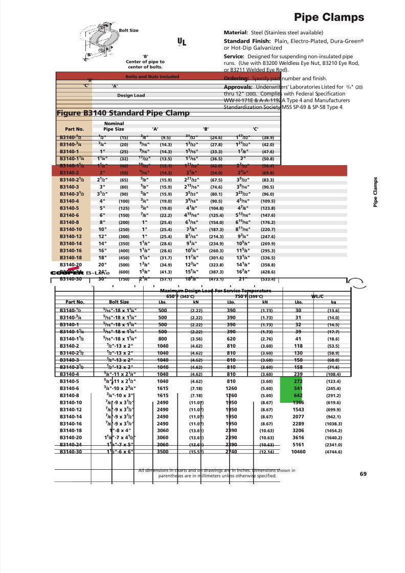
7/18/2019 PH Pipe Hanger Catalog
http://slidepdf.com/reader/full/ph-pipe-hanger-catalog 71/224
Pipe Clamps
69All dimensions in charts and on drawings are in inches. Dimensions shown in
parentheses are in millimeters unless otherwise specified.
Figure B3140 Standard Pipe Clamp
Material: Steel (Stainless steel available)Standard Finish: Plain, Electro-Plated, Dura-Green ®
or Hot-Dip GalvanizedService: Designed for suspending non-insulated piperuns. (Use with B3200 Weldless Eye Nut, B3210 Eye Rod,or B3211 Welded Eye Rod).Ordering: Specify part number and finish.Approvals: Underwriters' Laboratories Listed for 3 / 4" (20)
thru 12" (300) . Complies with Federal SpecificationWW-H-171E & A-A-1192A Type 4 and ManufacturersStandardization Society MSS SP-69 & SP-58 Type 4.
Bolts and Nuts Included
'B'Center of pipe to
center of bolts.
Bolt Size
'A''C'
'C''B'
'B'
NominalPart No. Pipe Size 'A' 'B' 'C'
B3140- 1 / 2 1 / 2" (15) 3 / 8" (9.5) 31 / 32 " (24.6) 117 / 32" (38.9)
B3140- 3 / 4 3 / 4" (20) 9 / 16 " (14.3) 13 / 32 " (27.8) 121 / 32 " (42.0)
B3140-1 1" (25) 9 / 16 " (14.3) 15 / 16 " (33.3) 17 / 8" (47.6)
B3140-1 1 / 4 11 / 4" (32) 17 / 32 " (13.5) 17 / 16 " (36.5) 2" (50.8)
B3140-1 1 / 2 11 / 2" (40) 19 / 32 " (15.1) 121 / 32 " (42.0) 27 / 32" (56.4)
B3140-2 2" (50) 9 / 16 " (14.3) 21 / 8" (54.0) 23 / 4" (69.8)
B3140-2 1 / 2 21 / 2" (65) 5 / 8" (15.9) 221 / 32 " (67.5) 39 / 32" (83.3)
B3140-3 3"(80) 5
/ 8"
(15.9)2
15
/ 16
"(74.6)
39
/ 16
"(90.5)
B3140-3 1 / 2 31 / 2" (90) 5 / 8" (15.9) 35 / 32 " (80.1) 325 / 32 " (96.0)
B3140-4 4" (100) 3 / 4" (19.0) 39 / 16 " (90.5) 45 / 16" (109.5)
B3140-5 5" (125) 3 / 4" (19.0) 41 / 8" (104.8) 47 / 8" (123.8)
B3140-6 6" (150) 7 / 8" (22.2) 415 / 16 " (125.4) 513 / 16 " (147.6)
B3140-8 8" (200) 1" (25.4) 61 / 16 " (154.0) 615 / 16 " (176.2)
B3140-10 10" (250) 1" (25.4) 73 / 8" (187.3) 811 / 16 " (220.7)
B3140-12 12" (300) 1" (25.4) 87 / 16 " (214.3) 93 / 4" (247.6)
B3140-14 14" (350) 11 / 8" (28.6) 91 / 4" (234.9) 10 5 / 8" (269.9)
B3140-16 16" (400) 11 / 8" (28.6) 10 1 / 4" (260.3) 11 5 / 8" (295.3)
B3140-18 18" (450) 11 / 4" (31.7) 11 7 / 8" (301.6) 13 1 / 4" (336.5)
B3140-20 20" (500) 13 / 8" (34.9) 12 3 / 4" (323.8) 14 1 / 8" (358.8)
B3140-24 24" (600) 15 / 8" (41.3) 15 1 / 4" (387.3) 16 7 / 8" (428.6)
B3140-30 30" (750) 21 / 4" (57.1) 18 5 / 8" (473.1) 21" (533.4)
Maximum Design Load For Service Temperature650 °F (343 °C) 750 °F (399 °C) Wt./C
Part No. Bolt Size Lbs. kN Lbs. kN Lbs. kg
B3140- 1 / 2 5 / 16 "-18 x 1 1 / 4" 500 (2.22) 390 (1.73) 30 (13.6)
B3140- 3 / 4 5 / 16 "-18 x 1 1 / 4" 500 (2.22) 390 (1.73) 31 (14.0)
B3140-1 5 / 16 "-18 x 1 1 / 4" 500 (2.22) 390 (1.73) 32 (14.5)
B3140-1 1 / 4 5 / 16 "-18 x 1 1 / 4" 500 (2.22) 390 (1.73) 39 (17.7)
B3140-1 1 / 2 5 / 16 "-18 x 1 1 / 4" 800 (3.56) 620 (2.76) 41 (18.6)
B3140-2 1 / 2"-13 x 2" 1040 (4.62) 810 (3.60) 118 (53.5)
B3140-2 1 / 2 1 / 2"-13 x 2" 1040 (4.62) 810 (3.60) 130 (58.9)
B3140-3 1 / 2"-13 x 2" 1040 (4.62) 810 (3.60) 150 (68.0)
B3140-3 1 / 2 1 / 2"-13 x 2" 1040 (4.62) 810 (3.60) 158 (71.6)
B3140-4 5 / 8"-11 x 2 1 / 4" 1040 (4.62) 810 (3.60) 239 (108.4)
B3140-5 5 / 8"-11 x 2 1 / 2" 1040 (4.62) 810 (3.60) 272 (123.4)
B3140-6 3 / 4"-10 x 2 3 / 4" 1615 (7.18) 1260 (5.60) 541 (245.4)
B3140-8 3 / 4"-10 x 3" 1615 (7.18) 1260 (5.60) 642 (291.2)
B3140-10 7 / 8"-9 x 3 1 / 2" 2490 (11.07) 1950 (8.67) 1366 (619.6)
B3140-12 7 / 8"-9 x 3 1 / 2" 2490 (11.07) 1950 (8.67) 1543 (699.9)
B3140-14 7 / 8"-9 x 3 1 / 2" 2490 (11.07) 1950 (8.67) 2077 (942.1)
B3140-16 7 / 8"-9 x 3 1 / 2" 2490 (11.07) 1950 (8.67) 2289 (1038.3)B3140-18 1"-8 x 4" 3060 (13.61) 2390 (10.63) 3206 (1454.2)
B3140-20 1 1 / 8"-7 x 4 1 / 2" 3060 (13.61) 2390 (10.63) 3616 (1640.2)
B3140-24 1 1 / 4"-7 x 5" 3060 (13.61) 2390 (10.63) 5161 (2341.0)
B3140-30 1 1 / 2"-6 x 6" 3500 (15.57) 2740 (12.14) 10460 (4744.6)
Design Load
UL®
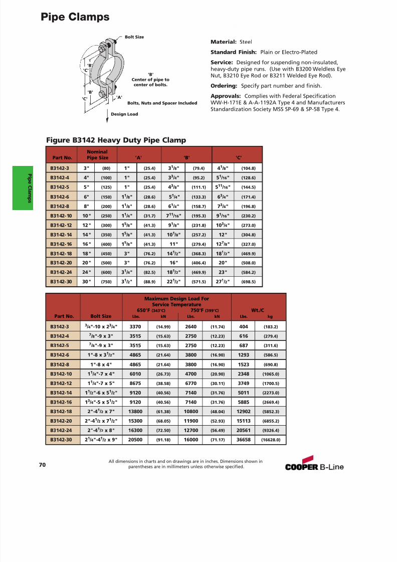
7/18/2019 PH Pipe Hanger Catalog
http://slidepdf.com/reader/full/ph-pipe-hanger-catalog 72/224
Pipe Clamps
70All dimensions in charts and on drawings are in inches. Dimensions shown in
parentheses are in millimeters unless otherwise specified.
Material: Steel
Standard Finish: Plain or Electro-Plated
Service: Designed for suspending non-insulated,heavy-duty pipe runs. (Use with B3200 Weldless EyeNut, B3210 Eye Rod or B3211 Welded Eye Rod).
Ordering: Specify part number and finish.
Approvals: Complies with Federal SpecificationWW-H-171E & A-A-1192A Type 4 and ManufacturersStandardization Society MSS SP-69 & SP-58 Type 4.
Figure B3142 Heavy Duty Pipe Clamp
Bolts, Nuts and Spacer Included
'B'Center of pipe tocenter of bolts.
Bolt Size
'A''C'
'C''B'
'B'
NominalPart No. Pipe Size 'A' 'B' 'C'
B3142-3 3" (80) 1" (25.4) 31 / 8" (79.4) 41 / 8" (104.8)
B3142-4 4" (100) 1" (25.4) 33 / 4" (95.2) 51 / 16 " (128.6)
B3142-5 5" (125) 1" (25.4) 43 / 8" (111.1) 511 / 16 " (144.5)
B3142-6 6" (150) 11 / 8" (28.6) 51 / 4" (133.3) 63 / 4" (171.4)
B3142-8 8" (200) 11 / 8" (28.6) 61 / 4" (158.7) 73 / 4" (196.8)
B3142-10 10" (250) 11 / 4" (31.7) 711 / 16 " (195.3) 91 / 16 " (230.2)
B3142-12 12" (300) 15 / 8" (41.3) 91 / 8" (231.8) 10 3 / 4" (273.0)
B3142-14 14" (350) 15 / 8" (41.3) 10 1 / 8" (257.2) 12" (304.8)
B3142-16 16" (400) 15 / 8" (41.3) 11" (279.4) 12 7 / 8" (327.0)
B3142-18 18" (450) 3" (76.2) 14 1 / 2" (368.3) 18 1 / 2" (469.9)
B3142-20 20" (500) 3" (76.2) 16" (406.4) 20" (508.0)
B3142-24 24" (600) 31 / 4" (82.5) 18 1 / 2" (469.9) 23" (584.2)
B3142-30 30" (750) 31 / 2" (88.9) 22 1 / 2" (571.5) 27 1 / 2" (698.5)
Maximum Design Load ForService Temperature
650 °F (343 °C) 750 °F (399 °C) Wt./CPart No. Bolt Size Lbs. kN Lbs. kN Lbs. kg
B3142-3 3 / 4"-10 x 2 3 / 4" 3370 (14.99) 2640 (11.74) 404 (183.2)
B3142-4 7 / 8"-9 x 3" 3515 (15.63) 2750 (12.23) 616 (279.4)
B3142-5 7 / 8"-9 x 3" 3515 (15.63) 2750 (12.23) 687 (311.6)
B3142-6 1"-8 x 3 1 / 2" 4865 (21.64) 3800 (16.90) 1293 (586.5)
B3142-8 1"-8 x 4" 4865 (21.64) 3800 (16.90) 1523 (690.8)
B3142-10 1 1 / 4"-7 x 4" 6010 (26.73) 4700 (20.90) 2348 (1065.0)
B3142-12 1 1 / 4"-7 x 5" 8675 (38.58) 6770 (30.11) 3749 (1700.5)
B3142-14 1 1 / 2"-6 x 5 1 / 2" 9120 (40.56) 7140 (31.76) 5011 (2273.0)
B3142-16 1 3 / 4"-5 x 5 1 / 2" 9120 (40.56) 7140 (31.76) 5885 (2669.4)
B3142-18 2"-4 1 / 2 x 7" 13800 (61.38) 10800 (48.04) 12902 (5852.3)
B3142-20 2"-4 1 / 2 x 7 1 / 2" 15300 (68.05) 11900 (52.93) 15113 (6855.2)
B3142-24 2"-4 1 / 2 x 8" 16300 (72.50) 12700 (56.49) 20561 (9326.4)
B3142-30 2 1 / 4"-4 1 / 2 x 9" 20500 (91.18) 16000 (71.17) 36658 (16628.0)
Design Load
P i peC l amps
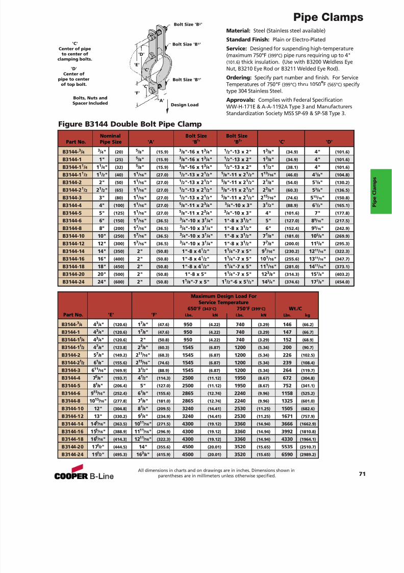
7/18/2019 PH Pipe Hanger Catalog
http://slidepdf.com/reader/full/ph-pipe-hanger-catalog 73/224
Pipe Clamps
71All dimensions in charts and on drawings are in inches. Dimensions shown in
parentheses are in millimeters unless otherwise specified.
Figure B3144 Double Bolt Pipe Clamp
Material: Steel (Stainless steel available)
Standard Finish: Plain or Electro-Plated
Service: Designed for suspending high-temperature(maximum 750 °F (399°C) pipe runs requiring up to 4"(101.6) thick insulation. (Use with B3200 Weldless EyeNut, B3210 Eye Rod or B3211 Welded Eye Rod).
Ordering: Specify part number and finish. For ServiceTemperatures of 750 °F (399 °C) thru 1050 oF (565°C) specifytype 304 Stainless Steel.
Approvals: Complies with Federal SpecificationWW-H-171E & A-A-1192A Type 3 and ManufacturersStandardization Society MSS SP-69 & SP-58 Type 3.
Bolts, Nuts andSpacer Included
'C'Center of pipe
to center ofclamping bolts.
'D'Center of
pipe to centerof top bolt.
Bolt Size 'B 2 '
Bolt Size 'B 1 '
Bolt Size 'B 1 '
'A''F'
'E'
'C'
'C'
'D'
Nominal Bolt Size Bolt SizePart No. Pipe Size 'A' 'B 1 ' 'B 2' 'C' 'D'
B3144- 3 / 4 3 / 4" (20) 5 / 8" (15.9) 3 / 8"-16 x 1 3 / 4" 1 / 2"-13 x 2" 1 3 / 8" (34.9) 4" (101.6)
B3144-1 1" (25) 5 / 8" (15.9) 3 / 8"-16 x 1 3 / 4" 1 / 2"-13 x 2" 1 3 / 8" (34.9) 4" (101.6)
B3144-1 1 / 4 11 / 4" (32) 5 / 8" (15.9) 3 / 8"-16 x 1 3 / 4" 1 / 2"-13 x 2" 1 1 / 2" (38.1) 4" (101.6)
B3144-1 1 / 2 11 / 2" (40) 11 / 16 " (27.0) 1 / 2"-13 x 2 1 / 2" 5 / 8"-11 x 2 1 / 2" 1 13 / 16 " (46.0) 41 / 8" (104.8)
B3144-2 2" (50) 11 / 16 " (27.0) 1 / 2"-13 x 2 1 / 2" 5 / 8"-11 x 2 1 / 2" 2 1 / 8" (54.0) 51 / 8" (130.2)
B3144-2 1 / 2 21 / 2" (65) 11 / 16 " (27.0) 1 / 2"-13 x 2 1 / 2" 5 / 8"-11 x 2 1 / 2" 2 3 / 8" (60.3) 53 / 8" (136.5)B3144-3 3" (80) 11 / 16 " (27.0) 1 / 2"-13 x 2 1 / 2" 5 / 8"-11 x 2 1 / 2" 2 15 / 16 " (74.6) 515 / 16" (150.8)
B3144-4 4" (100) 11 / 16 " (27.0) 5 / 8"-11 x 2 3 / 4" 3 / 4"-10 x 3" 3 1 / 2" (88.9) 61 / 2" (165.1)
B3144-5 5" (125) 11 / 16 " (27.0) 5 / 8"-11 x 2 3 / 4" 3 / 4"-10 x 3" 4" (101.6) 7" (177.8)
B3144-6 6" (150) 17 / 16 " (36.5) 3 / 4"-10 x 3 1 / 4" 1"-8 x 3 1 / 2" 5" (127.0) 89 / 16" (217.5)
B3144-8 8" (200) 17 / 16 " (36.5) 3 / 4"-10 x 3 1 / 4" 1"-8 x 3 1 / 2" 6" (152.4) 99 / 16" (242.9)
B3144-10 10" (250) 17 / 16 " (36.5) 3 / 4"-10 x 3 1 / 4" 1"-8 x 3 1 / 2" 7 1 / 8" (181.0) 10 5 / 8" (269.9)
B3144-12 12" (300) 17 / 16 " (36.5) 3 / 4"-10 x 3 1 / 4" 1"-8 x 3 1 / 2" 7 7 / 8" (200.0) 11 5 / 8" (295.3)
B3144-14 14" (350) 2" (50.8) 1"-8 x 4 1 / 2" 1 1 / 4"-7 x 5" 9 1 / 16 " (230.2) 12 11 / 16" (322.3)
B3144-16 16" (400) 2" (50.8) 1"-8 x 4 1 / 2" 1 1 / 4"-7 x 5" 10 1 / 16 " (255.6) 13 11 / 16" (347.7)
B3144-18 18" (450) 2" (50.8) 1"-8 x 4 1 / 2" 1 1 / 4"-7 x 5" 11 1 / 16 " (281.0) 14 11 / 16" (373.1)
B3144-20 20" (500) 2" (50.8) 1"-8 x 5" 1 1 / 4"-7 x 5" 12 3 / 8" (314.3) 15 7 / 8" (403.2)
B3144-24 24"(600)
2"(50.8)
11
/ 8"-7 x 5" 1
1
/ 2"-6 x 5
1
/ 2" 14
3
/ 4"
(374.6)17
7
/ 8"
(454.0)
Maximum Design Load ForService Temperature
650 °F (343 °C) 750 °F (399 °C) Wt./CPart No. 'E' 'F' Lbs. kN Lbs. kN Lbs. kg
B3144- 3 / 4 43 / 4" (120.6) 17 / 8" (47.6) 950 (4.22) 740 (3.29) 146 (66.2)
B3144-1 43 / 4" (120.6) 17 / 8" (47.6) 950 (4.22) 740 (3.29) 147 (66.7)
B3144-1 1 / 4 43 / 4" (120.6) 2" (50.8) 950 (4.22) 740 (3.29) 152 (68.9)
B3144-1 1 / 2 47 / 8" (123.8) 23 / 8" (60.3) 1545 (6.87) 1200 (5.34) 200 (90.7)
B3144-2 5 7 / 8" (149.2) 211 / 16 " (68.3) 1545 (6.87) 1200 (5.34) 226 (102.5)
B3144-2 1 / 2 61 / 8" (155.6) 215 / 16 " (74.6) 1545 (6.87) 1200 (5.34) 239 (108.4)
B3144-3 6 11 / 16 " (169.9) 31 / 2" (88.9) 1545 (6.87) 1200 (5.34) 264 (119.7)
B3144-4 75 / 8" (193.7) 4
1 / 2" (114.3) 2500 (11.12) 1950 (8.67) 672 (304.8)
B3144-5 8 1 / 8" (206.4) 5" (127.0) 2500 (11.12) 1950 (8.67) 752 (341.1)
B3144-6 9 15 / 16 " (252.4) 61 / 8" (155.6) 2865 (12.74) 2240 (9.96) 1158 (525.2)
B3144-8 10 15 / 16" (277.8) 71 / 8" (181.0) 2865 (12.74) 2240 (9.96) 1325 (601.0)
B3144-10 12" (304.8) 81 / 4" (209.5) 3240 (14.41) 2530 (11.25) 1505 (682.6)
B3144-12 13" (330.2) 91 / 4" (234.9) 3240 (14.41) 2530 (11.25) 1671 (757.9)
B3144-14 14 5 / 16 " (363.5) 1011 / 16" (271.5) 4300 (19.12) 3360 (14.94) 3666 (1662.9)
B3144-16 15 5 / 16 " (388.9) 11 11 / 16" (296.9) 4300 (19.12) 3360 (14.94) 3992 (1810.8)
B3144-18 16 5 / 16 " (414.3) 1211 / 16" (322.3) 4300 (19.12) 3360 (14.94) 4330 (1964.1)
B3144-20 17 1 / 2" (444.5) 14" (355.6) 4500 (20.01) 3520 (15.65) 5535 (2510.7)
B3144-24 19 1 / 2" (495.3) 16 3 / 8" (415.9) 4500 (20.01) 3520 (15.65) 6590 (2989.2)
Design Load
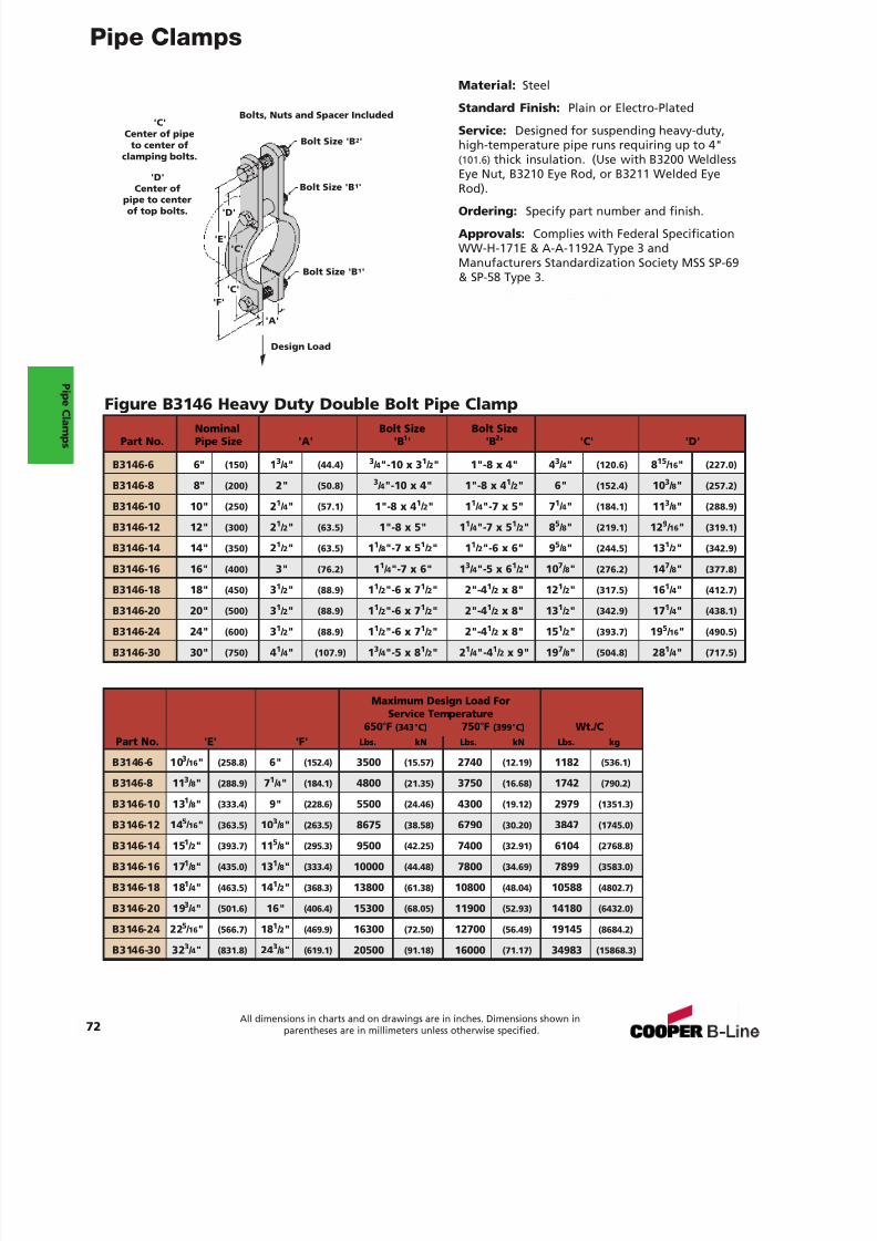
7/18/2019 PH Pipe Hanger Catalog
http://slidepdf.com/reader/full/ph-pipe-hanger-catalog 74/224
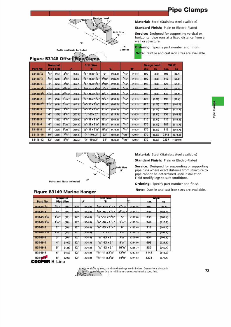
7/18/2019 PH Pipe Hanger Catalog
http://slidepdf.com/reader/full/ph-pipe-hanger-catalog 75/224
Pipe Clamps
73All dimensions in charts and on drawings are in inches. Dimensions shown in
parentheses are in millimeters unless otherwise specified.
Material: Steel (Stainless steel available)
Standard Finish: Plain or Electro-Plated
Service: Designed for supporting vertical orhorizontal pipe runs at a fixed distance from awall or structure.
Ordering: Specify part number and finish.
Note: Ductile and cast iron sizes are available.
Material: Steel (Stainless steel available)
Standard Finish: Plain or Electro-Plated
Service: Designed for suspending or supportingpipe runs where exact distance from structure topipe cannot be determined until installation.Field modify legs to suit conditions.
Ordering: Specify part number and finish.
Note: Ductile and cast iron sizes are available.
Figure B3148 Offset Pipe Clamp
Figure B3149 Marine Hanger
Bolts and Nuts Included
Bolt Size'B'
'C''A'
Bolts and Nuts Included
Bolt Size'B'
'C'
'A'
'H'2 Holes
Nominal Bolt Size Wt./CPart No. Pipe Size 'A' 'B' 'C' Lbs. kg
B3149- 3 / 4 3 / 4" (20) 12" (304.8) 3 / 8"-16x 1 1 / 2" 4 7 / 16 " (112.7) 182 (82.5)
B3149-1 1" (25) 12" (304.8) 3 / 8"-16 x 1 1 / 2" 4 11 / 16 " (119.1) 230 (104.3)
B3149-1 1 / 4 11 / 4" (32) 12" (304.8) 3 / 8"-16 x 1 1 / 2" 5" (127.0) 239 (108.4)
B3149-1 1 / 2 11 / 2" (40) 12" (304.8) 3 / 8"-16 x 1 1 / 2" 5 1 / 4" (133.3) 244 (110.7)
B3149-2 2" (50) 12" (304.8) 1 / 2"-13 x 1 3 / 4" 6" (152.4) 319 (144.7)
B3149-2 1 / 2 21 / 2" (65) 12" (304.8) 1 / 2"-13 x 2" 7 1 / 4" (184.1) 434 (196.8)
B3149-3 3" (80) 12" (304.8) 1 / 2"-13 x 2" 7 7 / 8" (200.0) 454 (205.9)
B3149-4 4" (100) 12" (304.8) 1 / 2"-13 x 2" 9 1 / 4" (234.9) 493 (223.6)
B3149-5 5" (125) 12" (304.8) 1 / 2"-13 x 2 " 10 1 / 2" (266.7) 530 (240.4)
B3149-6 6" (150) 12" (304.8) 5 / 8"-11 x 2 1 / 2" 12 1 / 2" (317.5) 1142 (518.0)
B3149-8 8" (200) 12" (304.8) 5 / 8"-11 x 2 1 / 2" 14 5 / 8" (371.5) 1273 (577.4)
Nominal Bolt Size Design Load Wt./CPart No. Pipe Size 'A' 'B' 'C' 'H' Lbs. kN Lbs. kg
B3148- 1 / 2 1 / 2" (15) 21 / 2" (63.5) 3 / 8"-16 x 1 1 / 2" 6" (152.4) 7 / 16 " (11.1) 190 (.84) 106 (48.1)
B3148- 3 / 4 3 / 4" (20) 21 / 2" (63.5) 3 / 8"-16 x 1 1 / 2" 7 5 / 16 " (185.7) 7 / 16 " (11.1) 190 (.84) 112 (50.8)
B3148-1 1" (25) 25 / 8" (66.7) 3 / 8"-16 x 1 1 / 2" 7 9 / 16 " (192.1) 7 / 16 " (11.1) 190 (.84) 123 (55.8)
B3148-1 1 / 4 11 / 4" (32) 213 / 16 " (71.4) 3 / 8"-16 x 1 1 / 2" 7 7 / 8" (200.0) 7 / 16 " (11.1) 190 (.84) 133 (60.3)
B3148-1 1 / 2 11 / 2" (40) 215 / 16 " (74.6) 3 / 8"-16 x 1 1 / 2" 8 1 / 4" (209.5) 7 / 16 " (11.1) 190 (.84) 140 (63.5)
B3148-2 2" (50) 33 / 16 " (81.0) 3 / 8"-16 x 1 3 / 4" 9 1 / 8" (231.8) 7 / 16 " (11.1) 420 (1.87) 195 (88.4)
B3148-2 1 / 2 21 / 2" (65) 37 / 16 " (87.3) 3 / 8"-16 x 1 3 / 4" 10 1 / 2" (266.7) 7 / 16 " (11.1) 420 (1.87) 226 (102.5)
B3148-3 3" (80) 33 / 4" (95.2) 3 / 8"-16 x 1 3 / 4" 11 1 / 8" (282.6) 7 / 16 " (11.1) 420 (1.87) 244 (110.7)
B3148-4 4" (100) 41 / 4" (107.9) 1 / 2"-13x 2" 12 1 / 2" (317.5) 9 / 16 " (14.3) 610 (2.71) 358 (162.4)
B3148-5 5" (125) 43 / 4" (120.6) 1 / 2"-13 x 2 1 / 4" 13 3 / 4" (349.2) 9 / 16 " (14.3) 610 (2.71) 415 (188.2)
B3148-6 6" (150) 55 / 16 " (134.9) 1 / 2"-13 x 2 1 / 4" 16 1 / 2" (419.1) 9 / 16 " (14.3) 870 (3.87) 685 (310.7)
B3148-8 8" (200) 65 / 16 " (160.3) 1 / 2"-13 x 2 1 / 2" 18 5 / 8" (473.1) 9 / 16 " (14.3) 870 (3.87) 815 (369.7)
B3148-10 10" (250) 73 / 4" (196.8) 3 / 4"-10x 3" 23" (584.2) 13 / 16 " (20.6) 870 (3.87) 2142 (971.6)
B3148-12 12" (300) 83 / 4" (222.2) 3 / 4"-10 x 3" 25" (635.0) 13 / 16 " (20.6) 870 (3.87) 2337 (1060.0)
Design Load

7/18/2019 PH Pipe Hanger Catalog
http://slidepdf.com/reader/full/ph-pipe-hanger-catalog 76/224
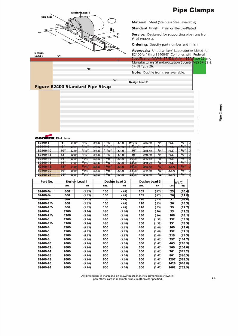
7/18/2019 PH Pipe Hanger Catalog
http://slidepdf.com/reader/full/ph-pipe-hanger-catalog 77/224
Pipe Clamps
75All dimensions in charts and on drawings are in inches. Dimensions shown in
parentheses are in millimeters unless otherwise specified.
Figure B2400 Standard Pipe Strap
Bolt Size‘A’
'B'
'T'
'C'
'W'Design Load 2
DesignLoad 3
Design Load 1
Pipe Size
Material: Steel (Stainless Steel available)
Standard Finish: Plain or Electro-Plated
Service: Designed for supporting pipe runs fromstrut supports.
Ordering: Specify part number and finish.
Approvals: Underwriters' Laboratories Listed for
B2400-3
/ 4" thru B2400-8".Complies with FederalSpecification WW-H-171E & A-A-1192A Type 26 andManufacturers Standardization Society MSS SP-69 &SP-58 Type 26.
Note: Ductile iron sizes available.
UL®
Part No. Pipe Size ‘A’ ‘B’ ‘C’ ‘T’ ‘W’
B2400- 1 / 2 1 / 2” (15) 5 / 16 ” (7.9) 7 / 16 ” (11.1) 2 13 / 16 ” (71.4) 10 Ga. (3.4) 1 5 / 8” (41.3)
B2400- 3 / 4 3 / 4” (20) 5 / 16 ” (7.9) 7 / 16 ” (11.1) 3” (76.2) 10 Ga. (3.4) 1 5 / 8” (41.3)
B2400-1 1” (25) 5 / 16 ” (7.9) 7 / 16 ” (11.1) 3 17 / 32 ” (89.7) 10 Ga. (3.4) 1 5 / 8” (41.3)
B2400-1 1 / 4 1 1 / 4” (32) 5 / 16 ” (7.9) 7 / 16 ” (11.1) 3 3 / 4” (95.2) 10 Ga. (3.4) 1 5 / 8” (41.3)B2400-1 1 / 2 1 1 / 2” (40) 5 / 16 ” (7.9) 7 / 16 ” (11.1) 4 1 / 16 ” (103.2) 10 Ga. (3.4) 1 5 / 8” (41.3)
B2400-2 2” (50) 7 / 16 ” (11.1) 11 / 16 ” (17.4) 5 21 / 32 ” (143.6) 1 / 4” (6.3) 1 5 / 8” (41.3)
B2400-2 1 / 2 2 1 / 2” (65) 7 / 16 ” (11.1) 11 / 16 ” (17.4) 6 5 / 32 ” (156.3) 1 / 4” (6.3) 1 5 / 8” (41.3)
B2400-3 3” (80) 7 / 16 ” (11.1) 11 / 16 ” (17.4) 6 25 / 32 ” (172.2) 1 / 4” (6.3) 1 5 / 8” (41.3)
B2400-3 1 / 2 3 1 / 2” (90) 7 / 16 ” (11.1) 11 / 16 ” (17.4) 7 9 / 32 ” (184.9) 1 / 4” (6.3) 1 5 / 8” (41.3)
B2400-4 4” (100) 9 / 16 ” (14.3) 11 / 16 ” (17.4) 7 25 / 32 ” (197.6) 1 / 4” (6.3) 1 5 / 8” (41.3)
B2400-5 5” (125) 9 / 16 ” (14.3) 11 / 16 ” (17.4) 8 7 / 8” (225.4) 1 / 4” (6.3) 1 5 / 8” (41.3)
B2400-6 6” (150) 9 / 16 ” (14.3) 11 / 16 ” (17.4) 9 15 / 16 ” (252.4) 1 / 4” (6.3) 1 5 / 8” (41.3)
B2400-8 8” (200) 9 / 16 ” (14.3) 11 / 16 ” (17.4) 11 31 / 32 ” (304.0) 1 / 4” (6.3) 1 5 / 8” (41.3)
B2400-10 10” (250) 9 / 16 ” (14.3) 11 / 16 ” (17.4) 14” (355.6) 1 / 4” (6.3) 1 5 / 8” (41.3)
B2400-12 12” (300) 9 / 16 ” (14.3) 11 / 16 ” (17.4) 16” (406.4) 1 / 4” (6.3) 1 5 / 8” (41.3)
B2400-14 14” (350) 15 / 16 ” (23.8) 1 5 / 16 ” (33.3) 20 3 / 8” (517.5) 3 / 8” (9.5) 1 3 / 4” (44.4)
B2400-16 16” (400) 15 / 16 ” (23.8) 1 5 / 16 ” (33.3) 22 3 / 8” (568.3) 3 / 8” (9.5) 1 3 / 4” (44.4)
B2400-18 18” (450) 15 / 16 ” (23.8) 1 5 / 16 ” (33.3) 26 1 / 8” (663.6) 1 / 2” (12.7) 1 3 / 4” (44.4)B2400-20 20” (500) 15 / 16 ” (23.8) 1 5 / 16 ” (33.3) 28 1 / 8” (714.4) 1 / 2” (12.7) 1 3 / 4” (44.4)
B2400-24 24” (600) 15 / 16 ” (23.8) 1 5 / 16 ” (33.3) 32 1 / 8” (816.0) 1 / 2” (12.7) 1 3 / 4” (44.4)
Part No. Design Load 1 Design Load 2 Design Load 3 Wt./CLbs. kN Lbs. kN Lbs. kN Lbs. kg
B2400- 1 / 2 600 (2.67) 150 (.67) 105 (.47) 23 (10.4)B2400- 3 / 4 600 (2.67) 150 (.67) 105 (.47) 26 (11.8)B2400-1 600 (2.67) 150 (.67) 120 (.53) 31 (14.0)B2400-1 1 / 4 600 (2.67) 150 (.67) 120 (.53) 36 (16.3)B2400-1 1 / 2 600 (2.67) 150 (.67) 120 (.53) 39 (17.7)B2400-2 1200 (5.34) 480 (2.14) 180 (.80) 93 (42.2)B2400-2 1 / 2 1200 (5.34) 480 (2.14) 180 (.80) 106 (48.1)B2400-3 1200 (5.34) 480 (2.14) 300 (1.33) 132 (59.9)B2400-3 1 / 2 1200 (5.34) 480 (2.14) 300 (1.33) 151 (68.5)B2400-4 1500 (6.67) 600 (2.67) 450 (2.00) 160 (72.6)B2400-5 1500 (6.67) 600 (2.67) 450 (2.00) 192 (87.1)B2400-6 1500 (6.67) 600 (2.67) 450 (2.00) 219 (99.3)B2400-8 2000 (8.90) 800 (3.56) 600 (2.67) 297 (134.7)B2400-10 2000 (8.90) 800 (3.56) 600 (2.67) 465 (210.9)B2400-12 2000 (8.90) 800 (3.56) 600 (2.67) 560 (254.0)B2400-14 2000 (8.90) 800 (3.56) 600 (2.67) 761 (345.2)B2400-16 2000 (8.90) 800 (3.56) 600 (2.67) 861 (390.5)B2400-18 2000 (8.90) 800 (3.56) 600 (2.67) 1297 (588.3)B2400-20 2000 (8.90) 800 (3.56) 600 (2.67) 1426 (646.8)B2400-24 2000 (8.90) 800 (3.56) 600 (2.67) 1682 (762.9)
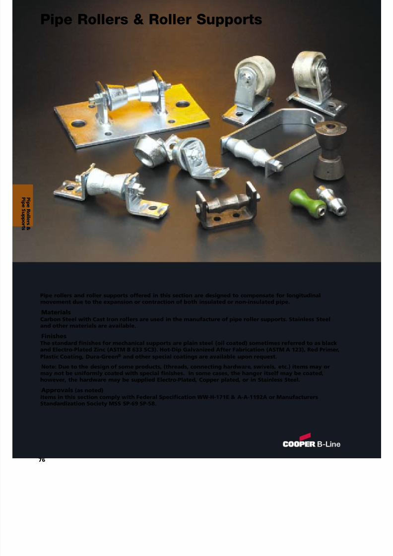
7/18/2019 PH Pipe Hanger Catalog
http://slidepdf.com/reader/full/ph-pipe-hanger-catalog 78/224
Pipe rollers and roller supports offered in this section are designed to compensate for longitudinalmovement due to the expansion or contraction of both insulated or non-insulated pipe.
MaterialsCarbon Steel with Cast Iron rollers are used in the manufacture of pipe roller supports. Stainless Steeland other materials are available.
FinishesThe standard finishes for mechanical supports are plain steel (oil coated) sometimes referred to as blackand Electro-Plated Zinc (ASTM B 633 SC3). Hot-Dip Galvanized After Fabrication (ASTM A 123), Red Primer,Plastic Coating, Dura-Green ® and other special coatings are available upon request.
Note: Due to the design of some products, (threads, connecting hardware, swivels, etc.) items may ormay not be uniformly coated with special finishes. In some cases, the hanger itself may be coated,however, the hardware may be supplied Electro-Plated, Copper plated, or in Stainless Steel.
Approvals (as noted)Items in this section comply with Federal Specification WW-H-171E & A-A-1192A or ManufacturersStandardization Society MSS SP-69 SP-58.
P i peR ol l er s &
76
Pipe Rollers & Roller Supports
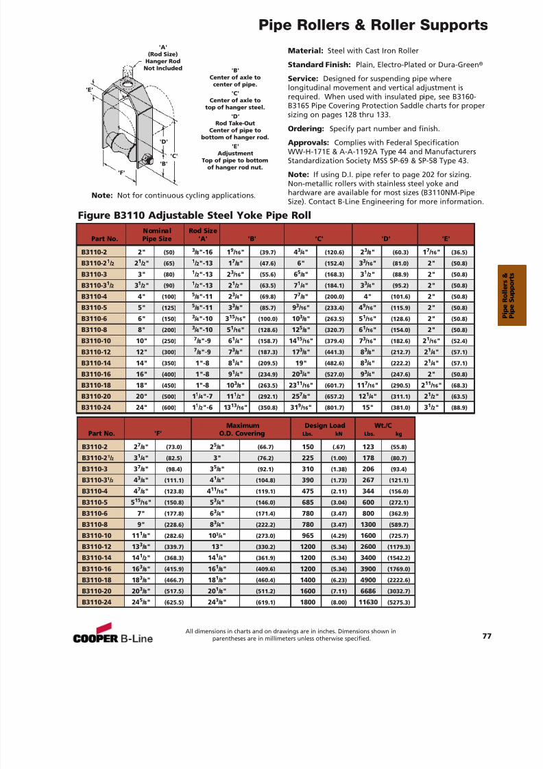
7/18/2019 PH Pipe Hanger Catalog
http://slidepdf.com/reader/full/ph-pipe-hanger-catalog 79/224
Pipe Rollers & Roller Supports
Material: Steel with Cast Iron Roller
Standard Finish: Plain, Electro-Plated or Dura-Green ®
Service: Designed for suspending pipe wherelongitudinal movement and vertical adjustment isrequired. When used with insulated pipe, see B3160-B3165 Pipe Covering Protection Saddle charts for propersizing on pages 128 thru 133.
Ordering: Specify part number and finish.
Approvals: Complies with Federal SpecificationWW-H-171E & A-A-1192A Type 44 and ManufacturersStandardization Society MSS SP-69 & SP-58 Type 43.
Note: If using D.I. pipe refer to page 202 for sizing.Non-metallic rollers with stainless steel yoke andhardware are available for most sizes (B3110NM-PipeSize). Contact B-Line Engineering for more information.
Figure B3110 Adjustable Steel Yoke Pipe Roll
'B'
'D'
'C'
'E'
'F'
'A'(Rod Size)
Hanger RodNot Included 'B'
Center of axle tocenter of pipe.
'C'Center of axle to
top of hanger steel.'D'
Rod Take-OutCenter of pipe to
bottom of hanger rod.'E'
AdjustmentTop of pipe to bottom
of hanger rod nut.
Nominal Rod SizePart No. Pipe Size 'A' 'B' 'C' 'D' 'E'
B3110-2 2" (50)3
/ 8"-16 19
/ 16 " (39.7) 43
/ 4" (120.6) 23
/ 8" (60.3) 17
/ 16 " (36.5)B3110-2 1 / 2 21 / 2" (65) 1 / 2"-13 1 7 / 8" (47.6) 6" (152.4) 33 / 16 " (81.0) 2" (50.8)
B3110-3 3" (80) 1 / 2"-13 2 3 / 16 " (55.6) 65 / 8" (168.3) 31 / 2" (88.9) 2" (50.8)
B3110-3 1 / 2 31 / 2" (90) 1 / 2"-13 2 1 / 2" (63.5) 71 / 4" (184.1) 33 / 4" (95.2) 2" (50.8)
B3110-4 4" (100) 5 / 8"-11 2 3 / 4" (69.8) 77 / 8" (200.0) 4" (101.6) 2" (50.8)
B3110-5 5" (125) 5 / 8"-11 3 3 / 8" (85.7) 93 / 16 " (233.4) 49 / 16 " (115.9) 2" (50.8)
B3110-6 6" (150) 3 / 4"-10 3 15 / 16 " (100.0) 10 3 / 8" (263.5) 51 / 16 " (128.6) 2" (50.8)
B3110-8 8" (200) 3 / 4"-10 5 1 / 16 " (128.6) 12 5 / 8" (320.7) 61 / 16 " (154.0) 2" (50.8)
B3110-10 10" (250) 7 / 8"-9 6 1 / 4" (158.7) 14 15 / 16 " (379.4) 73 / 16 " (182.6) 21 / 16 " (52.4)
B3110-12 12" (300) 7 / 8"-9 7 3 / 8" (187.3) 17 3 / 8" (441.3) 83 / 8" (212.7) 21 / 4" (57.1)
B3110-14 14" (350) 1"-8 8 1 / 4" (209.5) 19" (482.6) 83 / 4" (222.2) 21 / 4" (57.1)
B3110-16 16" (400) 1"-8 9 1 / 4" (234.9) 20 3 / 4" (527.0) 93 / 4" (247.6) 2" (50.8)
B3110-18 18" (450) 1"-8 10 3 / 8" (263.5) 23 11 / 16 " (601.7) 11 7 / 16 " (290.5) 211 / 16 " (68.3)
B3110-20 20" (500) 11 / 4"-7 11 1 / 2" (292.1) 25 7 / 8" (657.2) 12 1 / 4" (311.1) 21 / 2" (63.5)
B3110-24 24" (600) 11 / 2"-6 13 13 / 16 " (350.8) 31 9 / 16 " (801.7) 15" (381.0) 31 / 2" (88.9)
Maximum Design Load Wt./CPart No. 'F' O.D. Covering Lbs. kN Lbs. kg
B3110-2 2 7 / 8" (73.0) 25 / 8" (66.7) 150 (.67) 123 (55.8)
B3110-2 1 / 2 31 / 4" (82.5) 3" (76.2) 225 (1.00) 178 (80.7)
B3110-3 3 7 / 8" (98.4) 35 / 8" (92.1) 310 (1.38) 206 (93.4)
B3110-3 1 / 2 43 / 8" (111.1) 41 / 8" (104.8) 390 (1.73) 267 (121.1)
B3110-4 4 7 / 8" (123.8) 411 / 16 " (119.1) 475 (2.11) 344 (156.0)
B3110-5 5 15 / 16 " (150.8) 53 / 4" (146.0) 685 (3.04) 600 (272.1)
B3110-6 7" (177.8) 63 / 4" (171.4) 780 (3.47) 800 (362.9)
B3110-8 9" (228.6) 83 / 4" (222.2) 780 (3.47) 1300 (589.7)
B3110-10 11 1 / 8" (282.6) 10 3 / 4" (273.0) 965 (4.29) 1600 (725.7)
B3110-12 13 3 / 8" (339.7) 13" (330.2) 1200 (5.34) 2600 (1179.3)
B3110-14 14 1 / 2" (368.3) 14 1 / 4" (361.9) 1200 (5.34) 3400 (1542.2)
B3110-16 16 3 / 8" (415.9) 16 1 / 8" (409.6) 1200 (5.34) 3900 (1769.0)
B3110-18 18 3 / 8" (466.7) 18 1 / 8" (460.4) 1400 (6.23) 4900 (2222.6)
B3110-20 20 3 / 8" (517.5) 20 1 / 8" (511.2) 1600 (7.11) 6686 (3032.7)
B3110-24 24 5 / 8" (625.5) 24 3 / 8" (619.1) 1800 (8.00) 11630 (5275.3)
77All dimensions in charts and on drawings are in inches. Dimensions shown in
parentheses are in millimeters unless otherwise specified.
Note: Not for continuous cycling applications.
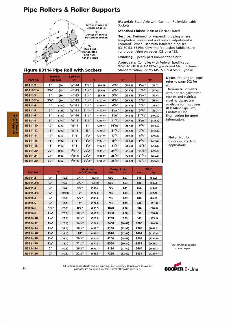
7/18/2019 PH Pipe Hanger Catalog
http://slidepdf.com/reader/full/ph-pipe-hanger-catalog 80/224
Pipe Rollers & Roller Supports
Material: Steel Axle with Cast Iron Roller/MalleableSockets
Standard Finish: Plain or Electro-Plated
Service: Designed for suspending piping wherelongitudinal movement and vertical adjustment isrequired. When used with insulated pipe, seeB3160-B3165 Pipe Covering Protection Saddle chartsfor proper sizing on pages 128 thru 133.
Ordering: Specify part number and finish
Approvals: Complies with Federal SpecificationWW-H-171E & A-A-1192A Type 42 and ManufacturersStandardization Society MSS SP-69 & SP-58 Type 41.Figure B3114 Pipe Roll with Sockets
'B'
'D'
'C''E'
'A'(Rod Size)
Hanger Rodand Nuts
Not Included
'D'Center of pipe to
center of axle.'E'
Center of axle tobottom of socket.
36" (900) availableupon request.
Nominal Rod SizePart No. Pipe Size 'A' 'B' 'C' 'D'
B3114-2 2" (50) 3 / 8"-16 2 5 / 8" (66.7) 41 / 8" (104.8) 19 / 16 " (39.7)
B3114-2 1 / 2 21 / 2" (65) 1 / 2"-13 3 1 / 8" (79.4) 47 / 8" (123.8) 17 / 8" (47.6)
B3114-3 3" (80) 1 / 2"-13 3 3 / 4" (95.2) 51 / 2" (139.7) 23 / 16 " (55.6)
B3114-3 1 / 2 31 / 2" (90) 1 / 2"-13 4 1 / 4" (107.9) 61 / 8" (155.6) 21 / 2" (63.5)
B3114-4 4" (100) 5 / 8"-11 4 3 / 4" (120.6) 63 / 4" (171.4) 23 / 4" (69.8)
B3114-5 5" (125) 5 / 8"-11 5 13 / 16 " (147.6) 81 / 16 " (204.8) 33 / 8" (85.7)
B3114-6 6" (150) 3 / 4"-10 6 7 / 8" (174.6) 99 / 16" (242.9) 315 / 16 " (100.0)
B3114-8 8" (200) 7 / 8"-9 8 7 / 8" (225.4) 11 15 / 16 " (303.2) 51 / 16 " (128.6)
B3114-10 10" (250) 7 / 8"-9 11" (279.4) 14 1 / 16 " (357.2) 61 / 4" (158.7)
B3114-12 12" (300) 7 / 8"-9 13" (330.2) 15 13 / 16 " (401.6) 73 / 8" (187.3)
B3114-14 14" (350) 1"-8 14 1 / 4" (361.9) 17 3 / 4" (450.8) 81 / 4" (209.5)
B3114-16 16" (400) 1"-8 16 1 / 4" (412.7) 19 3 / 4" (501.6) 91 / 4" (234.9)
B3114-18 18" (450) 1"-8 18 1 / 4" (463.5) 21 7 / 8" (555.6) 10 3 / 8" (263.5)
B3114-20 20" (500) 11 / 4"-7 20 1 / 4" (514.3) 24 1 / 4" (615.9) 11 1 / 2" (292.1)
B3114-24 24" (600) 11 / 2"-6 24 1 / 4" (615.9) 28 7 / 8" (733.4) 13 13 / 16 " (350.8)
B3114-30 30" (750) 11 / 2"-6 30 1 / 4" (768.3) 35 1 / 2" (901.7) 17 1 / 4" (438.1)
Maximum Design Load Wt./CPart No. 'E' O.D. Covering Lbs. kN Lbs. kg
B3114-2 3 / 4" (19.0) 31 / 4" (82.5) 600 (2.67) 119 (54.0)
B3114-2 1 / 2 3 / 4" (19.0) 33 / 4" (95.2) 660 (2.93) 140 (63.5)
B3114-3 3 / 4" (19.0) 41 / 2" (114.3) 700 (3.11) 158 (71.6)
B3114-3 1 / 2 3 / 4" (19.0) 5" (127.0) 750 (3.33) 170 (77.1)
B3114-4 3 / 4" (19.0) 57 / 8" (149.2) 750 (3.33) 188 (85.3)
B3114-5 3 / 4" (19.0) 7" (177.8) 750 (3.33) 246 (111.6)
B3114-6 1 1 / 8" (28.6) 81 / 4" (209.5) 1070 (4.76) 504 (228.6)
B3114-8 11
/ 8" (28.6) 10
1
/ 2" (266.7) 1350 (6.00) 658 (298.4)
B3114-10 1 1 / 8" (28.6) 12 3 / 4" (323.8) 1730 (7.69) 849 (385.1)
B3114-12 1 1 / 8" (28.6) 14 3 / 4" (374.6) 2400 (10.67) 1200 (544.3)
B3114-14 1 1 / 2" (38.1) 16 1 / 4" (412.7) 3130 (13.92) 2289 (1038.3)
B3114-16 1 1 / 2" (38.1) 18" (457.2) 3970 (17.66) 2497 (1132.6)
B3114-18 1 1 / 2" (38.1) 20 1 / 4" (514.3) 4200 (18.68) 2899 (1315.0)
B3114-20 1 1 / 2" (38.1) 22 1 / 2" (571.5) 4550 (20.24) 3637 (1649.7)
B3114-24 2" (50.8) 26 1 / 2" (673.1) 6160 (27.40) 5664 (2569.2)
B3114-30 2" (50.8) 32 1 / 2" (825.5) 7290 (32.42) 9437 (4280.6)
78All dimensions in charts and on drawings are in inches. Dimensions shown in
parentheses are in millimeters unless otherwise specified.
Notes: If using D.I. piperefer to page 202 forsizing.
Non-metallic rollerswith hot-dip galvanizedsockets and stainlesssteel hardware areavailable for most sizes(B3114NM-Pipe Size).Contact B-LineEngineering for moreinformation.
Note: Not forcontinuous cyclingapplications.
P i peR ol l er s &
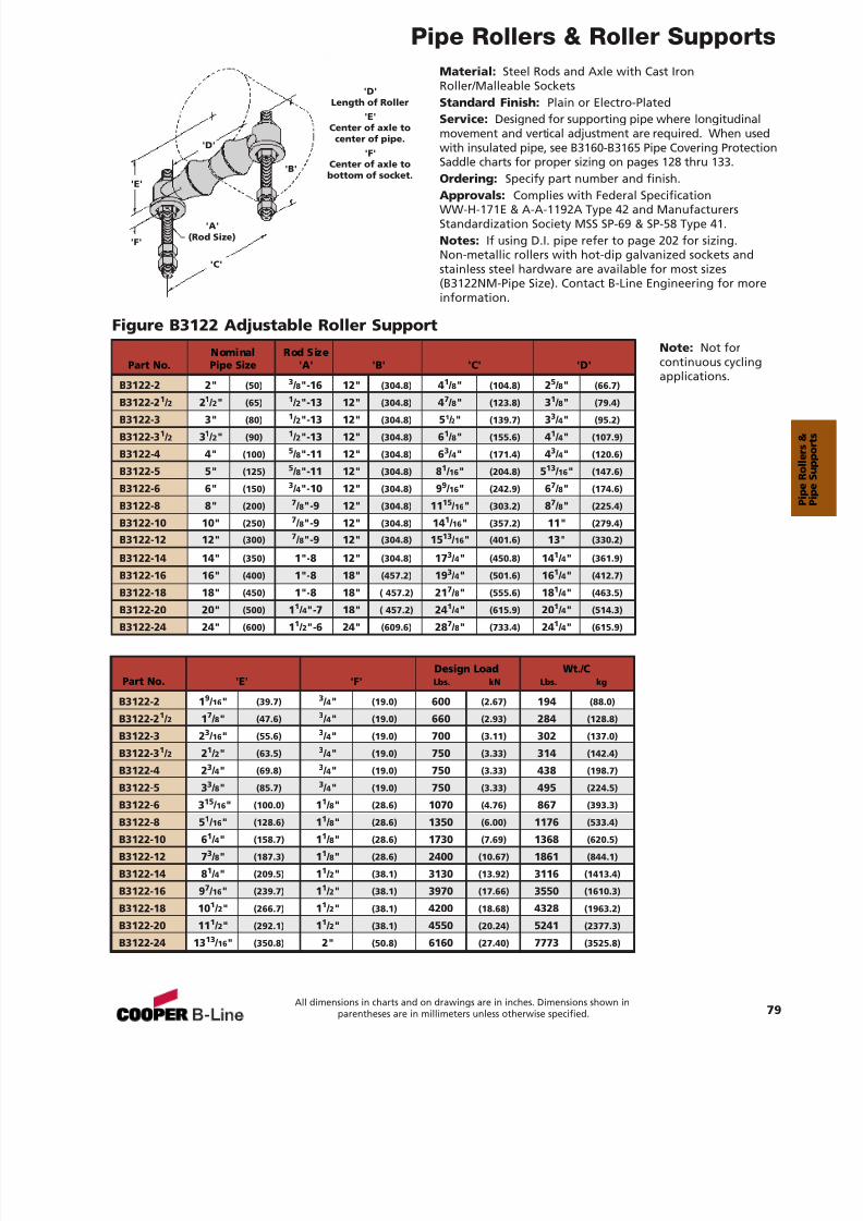
7/18/2019 PH Pipe Hanger Catalog
http://slidepdf.com/reader/full/ph-pipe-hanger-catalog 81/224
Pipe Rollers & Roller Supports
79All dimensions in charts and on drawings are in inches. Dimensions shown in
parentheses are in millimeters unless otherwise specified.
Material: Steel Rods and Axle with Cast IronRoller/Malleable SocketsStandard Finish: Plain or Electro-PlatedService: Designed for supporting pipe where longitudinalmovement and vertical adjustment are required. When usedwith insulated pipe, see B3160-B3165 Pipe Covering ProtectionSaddle charts for proper sizing on pages 128 thru 133.Ordering: Specify part number and finish.
Approvals: Complies with Federal SpecificationWW-H-171E & A-A-1192A Type 42 and ManufacturersStandardization Society MSS SP-69 & SP-58 Type 41.Notes: If using D.I. pipe refer to page 202 for sizing.Non-metallic rollers with hot-dip galvanized sockets andstainless steel hardware are available for most sizes(B3122NM-Pipe Size). Contact B-Line Engineering for moreinformation.
Figure B3122 Adjustable Roller Support
'B'
'C'
'F'
'A'(Rod Size)
'E'
'D'
'D'Length of Roller
'E'Center of axle to
center of pipe.'F'
Center of axle tobottom of socket.
Nominal Rod SizePart No. Pipe Size 'A' 'B' 'C' 'D'
B3122-2 2" (50) 3 / 8"-16 12" (304.8) 41 / 8" (104.8) 25 / 8" (66.7)
B3122-21 / 2 2
1 / 2" (65)
1 / 2"-13 12" (304.8) 4
7 / 8" (123.8) 3
1 / 8" (79.4)
B3122-3 3" (80) 1 / 2"-13 12" (304.8) 51 / 2" (139.7) 33 / 4" (95.2)
B3122-3 1 / 2 31 / 2" (90) 1 / 2"-13 12" (304.8) 61 / 8" (155.6) 41 / 4" (107.9)
B3122-4 4" (100) 5 / 8"-11 12" (304.8) 63 / 4" (171.4) 43 / 4" (120.6)
B3122-5 5" (125) 5 / 8"-11 12" (304.8) 81 / 16 " (204.8) 513 / 16 " (147.6)
B3122-6 6" (150) 3 / 4"-10 12" (304.8) 99 / 16 " (242.9) 67 / 8" (174.6)
B3122-8 8" (200) 7 / 8"-9 12" (304.8) 11 15 / 16 " (303.2) 87 / 8" (225.4)
B3122-10 10" (250) 7 / 8"-9 12" (304.8) 14 1 / 16 " (357.2) 11" (279.4)
B3122-12 12" (300) 7 / 8"-9 12" (304.8) 15 13 / 16 " (401.6) 13" (330.2)
B3122-14 14" (350) 1"-8 12" (304.8) 17 3 / 4" (450.8) 14 1 / 4" (361.9)
B3122-16 16" (400) 1"-8 18" (457.2) 19 3 / 4" (501.6) 16 1 / 4" (412.7)
B3122-18 18" (450) 1"-8 18" ( 457.2) 21 7 / 8" (555.6) 18 1 / 4" (463.5)
B3122-20 20" (500) 11 / 4"-7 18" ( 457.2) 24 1 / 4" (615.9) 20 1 / 4" (514.3)
B3122-24 24" (600) 11 / 2"-6 24" (609.6) 28 7 / 8" (733.4) 24 1 / 4" (615.9)
Design Load Wt./CPart No. 'E' 'F' Lbs. kN Lbs. kg
B3122-2 1 9 / 16 " (39.7) 3 / 4" (19.0) 600 (2.67) 194 (88.0)
B3122-2 1 / 2 17 / 8" (47.6) 3 / 4" (19.0) 660 (2.93) 284 (128.8)
B3122-3 2 3 / 16 " (55.6) 3 / 4" (19.0) 700 (3.11) 302 (137.0)
B3122-3 1 / 2 21 / 2" (63.5) 3 / 4" (19.0) 750 (3.33) 314 (142.4)
B3122-4 2 3 / 4" (69.8) 3 / 4" (19.0) 750 (3.33) 438 (198.7)
B3122-5 3 3 / 8" (85.7) 3 / 4" (19.0) 750 (3.33) 495 (224.5)
B3122-6 315
/ 16 " (100.0) 11 / 8" (28.6) 1070 (4.76) 867 (393.3)
B3122-8 5 1 / 16 " (128.6) 11 / 8" (28.6) 1350 (6.00) 1176 (533.4)
B3122-10 6 1 / 4" (158.7) 11 / 8" (28.6) 1730 (7.69) 1368 (620.5)
B3122-12 7 3 / 8" (187.3) 11 / 8" (28.6) 2400 (10.67) 1861 (844.1)
B3122-14 8 1 / 4" (209.5) 11 / 2" (38.1) 3130 (13.92) 3116 (1413.4)
B3122-16 9 7 / 16 " (239.7) 11 / 2" (38.1) 3970 (17.66) 3550 (1610.3)
B3122-18 10 1 / 2" (266.7) 11 / 2" (38.1) 4200 (18.68) 4328 (1963.2)
B3122-20 11 1 / 2" (292.1) 11 / 2" (38.1) 4550 (20.24) 5241 (2377.3)
B3122-24 13 13 / 16 " (350.8) 2" (50.8) 6160 (27.40) 7773 (3525.8)
Note: Not forcontinuous cyclingapplications.
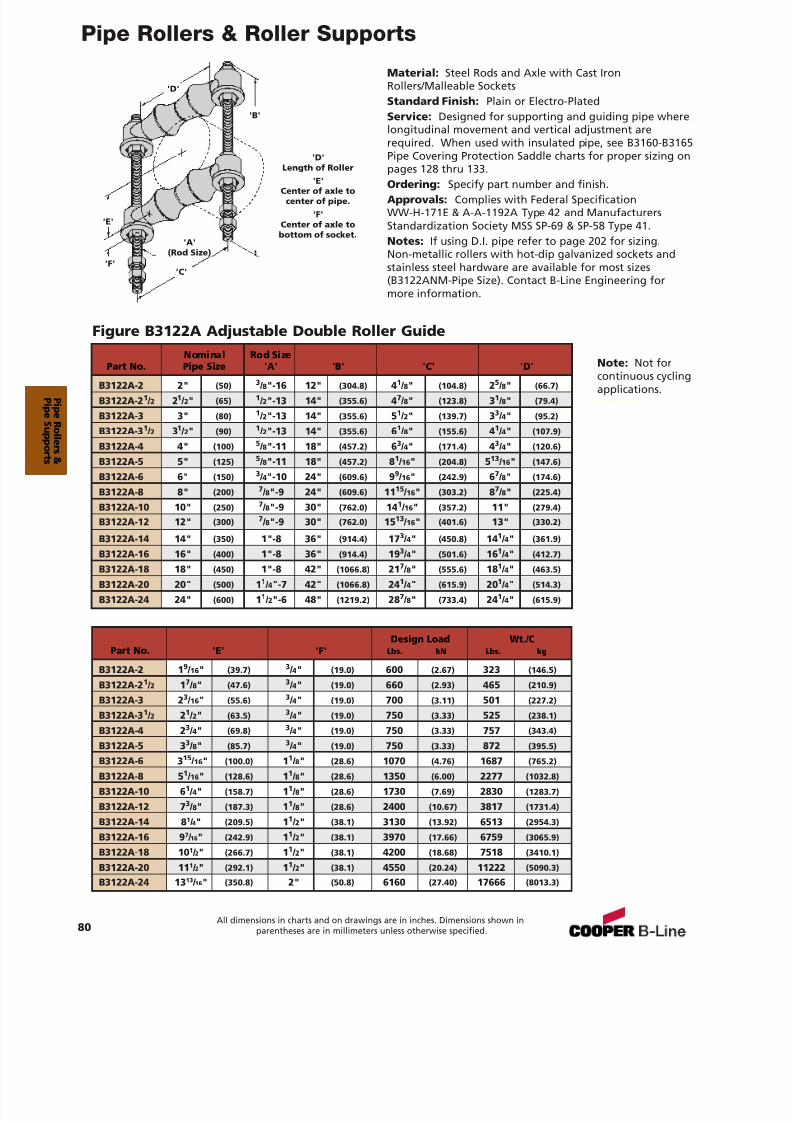
7/18/2019 PH Pipe Hanger Catalog
http://slidepdf.com/reader/full/ph-pipe-hanger-catalog 82/224
Pipe Rollers & Roller Supports
80All dimensions in charts and on drawings are in inches. Dimensions shown in
parentheses are in millimeters unless otherwise specified.
Material: Steel Rods and Axle with Cast IronRollers/Malleable SocketsStandard Finish: Plain or Electro-PlatedService: Designed for supporting and guiding pipe wherelongitudinal movement and vertical adjustment arerequired. When used with insulated pipe, see B3160-B3165Pipe Covering Protection Saddle charts for proper sizing onpages 128 thru 133.
Ordering: Specify part number and finish.Approvals: Complies with Federal SpecificationWW-H-171E & A-A-1192A Type 42 and ManufacturersStandardization Society MSS SP-69 & SP-58 Type 41.Notes: If using D.I. pipe refer to page 202 for sizing.Non-metallic rollers with hot-dip galvanized sockets andstainless steel hardware are available for most sizes(B3122ANM-Pipe Size). Contact B-Line Engineering formore information.
Figure B3122A Adjustable Double Roller Guide
'B'
'C''F'
'A'(Rod Size)
'E'
'D'
'D'Length of Roller
'E'Center of axle tocenter of pipe.
'F'Center of axle tobottom of socket.
Design Load Wt./CPart No. 'E' 'F' Lbs. kN Lbs. kg
B3122A-2 1 9 / 16 " (39.7) 3 / 4" (19.0) 600 (2.67) 323 (146.5)
B3122A-2 1 / 2 17 / 8" (47.6) 3 / 4" (19.0) 660 (2.93) 465 (210.9)
B3122A-3 2 3 / 16 " (55.6) 3 / 4" (19.0) 700 (3.11) 501 (227.2)
B3122A-3 1 / 2 21 / 2" (63.5) 3 / 4" (19.0) 750 (3.33) 525 (238.1)
B3122A-4 2 3 / 4" (69.8) 3 / 4" (19.0) 750 (3.33) 757 (343.4)
B3122A-5 3 3 / 8" (85.7) 3 / 4" (19.0) 750 (3.33) 872 (395.5)
B3122A-6 3 15 / 16 " (100.0) 11 / 8" (28.6) 1070 (4.76) 1687 (765.2)
B3122A-8 5 1 / 16 " (128.6) 11 / 8" (28.6) 1350 (6.00) 2277 (1032.8)
B3122A-10 6 1 / 4" (158.7) 11 / 8" (28.6) 1730 (7.69) 2830 (1283.7)
B3122A-12 7 3 / 8" (187.3) 11 / 8" (28.6) 2400 (10.67) 3817 (1731.4)
B3122A-14 8 1 / 4" (209.5) 11 / 2" (38.1) 3130 (13.92) 6513 (2954.3)
B3122A-16 9 7 / 16" (242.9) 11 / 2" (38.1) 3970 (17.66) 6759 (3065.9)
B3122A-18 10 1 / 2" (266.7) 11 / 2" (38.1) 4200 (18.68) 7518 (3410.1)
B3122A-20 11 1 / 2" (292.1) 11 / 2" (38.1) 4550 (20.24) 11222 (5090.3)
B3122A-24 13 13 / 16" (350.8) 2" (50.8) 6160 (27.40) 17666 (8013.3)
Nominal Rod Size
Part No. Pipe Size 'A' 'B' 'C' 'D'B3122A-2 2" (50) 3 / 8"-16 12" (304.8) 41 / 8" (104.8) 25 / 8" (66.7)
B3122A-2 1 / 2 21 / 2" (65) 1 / 2"-13 14" (355.6) 47 / 8" (123.8) 31 / 8" (79.4)
B3122A-3 3" (80) 1 / 2"-13 14" (355.6) 51 / 2" (139.7) 33 / 4" (95.2)
B3122A-3 1 / 2 31 / 2" (90) 1 / 2"-13 14" (355.6) 61 / 8" (155.6) 41 / 4" (107.9)
B3122A-4 4" (100) 5 / 8"-11 18" (457.2) 63 / 4" (171.4) 43 / 4" (120.6)
B3122A-5 5" (125) 5 / 8"-11 18" (457.2) 81 / 16 " (204.8) 513 / 16 " (147.6)
B3122A-6 6" (150) 3 / 4"-10 24" (609.6) 99 / 16 " (242.9) 67 / 8" (174.6)
B3122A-8 8" (200) 7 / 8"-9 24" (609.6) 11 15 / 16 " (303.2) 87 / 8" (225.4)
B3122A-10 10" (250) 7 / 8"-9 30" (762.0) 14 1 / 16 " (357.2) 11" (279.4)
B3122A-12 12" (300) 7 / 8"-9 30" (762.0) 15 13 / 16 " (401.6) 13" (330.2)
B3122A-14 14" (350) 1"-8 36" (914.4) 17 3 / 4" (450.8) 14 1 / 4" (361.9)
B3122A-16 16" (400) 1"-8 36" (914.4) 193 / 4" (501.6) 16
1 / 4" (412.7)
B3122A-18 18" (450) 1"-8 42" (1066.8) 21 7 / 8" (555.6) 18 1 / 4" (463.5)
B3122A-20 20" (500) 11 / 4"-7 42" (1066.8) 24 1 / 4" (615.9) 20 1 / 4" (514.3)
B3122A-24 24" (600) 11 / 2"-6 48" (1219.2) 28 7 / 8" (733.4) 24 1 / 4" (615.9)
Note: Not forcontinuous cyclingapplications.
P i peR ol l er s &
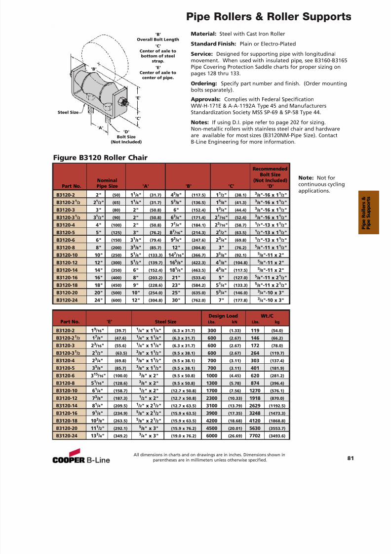
7/18/2019 PH Pipe Hanger Catalog
http://slidepdf.com/reader/full/ph-pipe-hanger-catalog 83/224
Pipe Rollers & Roller Supports
81All dimensions in charts and on drawings are in inches. Dimensions shown in
parentheses are in millimeters unless otherwise specified.
Material: Steel with Cast Iron Roller
Standard Finish: Plain or Electro-Plated
Service: Designed for supporting pipe with longitudinalmovement. When used with insulated pipe, see B3160-B3165Pipe Covering Protection Saddle charts for proper sizing onpages 128 thru 133.
Ordering: Specify part number and finish. (Order mounting
bolts separately).Approvals: Complies with Federal SpecificationWW-H-171E & A-A-1192A Type 45 and ManufacturersStandardization Society MSS SP-69 & SP-58 Type 44.
Notes: If using D.I. pipe refer to page 202 for sizing.Non-metallic rollers with stainless steel chair and hardwareare available for most sizes (B3120NM-Pipe Size). ContactB-Line Engineering for more information.
Figure B3120 Roller Chair
'B'
'C'
'A'
'E'
'D'Bolt Size
(Not Included)
Steel Size
'B'Overall Bolt Length
'C'Center of axle tobottom of steel
strap.'E'
Center of axle tocenter of pipe.
RecommendedBolt Size
Nominal (Not Included)Part No. Pipe Size 'A' 'B' 'C' 'D'
B3120-2 2" (50) 11 / 4" (31.7) 45 / 8" (117.5) 11 / 2" (38.1) 3 / 8"-16 x 1 1 / 2"B3120-2 1 / 2 21 / 2" (65) 11 / 4" (31.7) 53 / 8" (136.5) 15 / 8" (41.3) 3 / 8"-16 x 1 1 / 2"B3120-3 3" (80) 2" (50.8) 6" (152.4) 13 / 4" (44.4) 3 / 8"-16 x 1 1 / 2"B3120-3 1 / 2 31 / 2" (90) 2" (50.8) 63 / 4" (171.4) 21 / 16 " (52.4) 3 / 8"-16 x 1 1 / 2"B3120-4 4" (100) 2" (50.8) 71 / 4" (184.1) 25 / 16 " (58.7) 1 / 2"-13 x 1 1 / 2"B3120-5 5" (125) 3" (76.2) 87 / 16 " (214.3) 21 / 2" (63.5) 1 / 2"-13 x 1 1 / 2"B3120-6 6" (150) 31 / 8" (79.4) 93 / 4" (247.6) 23 / 4" (69.8) 1 / 2"-13 x 1 1 / 2"B3120-8 8" (200) 33 / 8" (85.7) 12" (304.8) 3" (76.2) 5 / 8"-11 x 1 1 / 2"B3120-10 10" (250) 51 / 4" (133.3) 14 7 / 16 " (366.7) 35 / 8" (92.1) 5 / 8"-11 x 2"B3120-12 12" (300) 51 / 2" (139.7) 16 5 / 8" (422.3) 41 / 8" (104.8) 5 / 8"-11 x 2"B3120-14 14" (350) 6" (152.4) 18 1 / 4" (463.5) 45 / 8" (117.5) 5 / 8"-11 x 2"B3120-16 16" (400) 8" (203.2) 21" (533.4) 5" (127.0) 5 / 8"-11 x 2 1 / 2"B3120-18 18" (450) 9" (228.6) 23" (584.2) 51 / 4" (133.3) 5 / 8"-11 x 2 1 / 2"B3120-20 20" (500) 10" (254.0) 25" (635.0) 53 / 4" (146.0) 3 / 4"-10 x 3"B3120-24 24" (600) 12" (304.8) 30" (762.0) 7" (177.8) 3 / 4"-10 x 3"
Design Load Wt./CPart No. 'E' Steel Size Lbs. kN Lbs. kg
B3120-2 1 9 / 16 " (39.7) 1 / 4" x 1 1 / 4" (6.3 x 31.7) 300 (1.33) 119 (54.0)
B3120-2 1 / 2 17 / 8" (47.6) 1 / 4" x 1 1 / 4" (6.3 x 31.7) 600 (2.67) 146 (66.2)
B3120-3 2 3 / 16 " (55.6) 1 / 4" x 1 1 / 4" (6.3 x 31.7) 600 (2.67) 172 (78.0)
B3120-3 1 / 2 21 / 2" (63.5) 3 / 8" x 1 1 / 2" (9.5 x 38.1) 600 (2.67) 264 (119.7)
B3120-4 2 3 / 4" (69.8) 3 / 8" x 1 1 / 2" (9.5 x 38.1) 700 (3.11) 303 (137.4)
B3120-5 3 3 / 8" (85.7) 3 / 8" x 1 1 / 2" (9.5 x 38.1) 700 (3.11) 401 (181.9)
B3120-6 3 15 / 16 " (100.0) 3 / 8" x 2" (9.5 x 50.8) 1000 (4.45) 620 (281.2)
B3120-8 5 1 / 16 " (128.6) 3 / 8" x 2" (9.5 x 50.8) 1300 (5.78) 874 (396.4)
B3120-10 6 1 / 4" (158.7) 1 / 2" x 2" (12.7 x 50.8) 1700 (7.56) 1270 (576.1)
B3120-12 7 3 / 8" (187.3) 1 / 2" x 2" (12.7 x 50.8) 2300 (10.33) 1918 (870.0)
B3120-14 8 1 / 4" (209.5) 1 / 2" x 2 1 / 2" (12.7 x 63.5) 3100 (13.79) 2629 (1192.5)
B3120-16 9 1 / 4" (234.9) 5 / 8" x 2 1 / 2" (15.9 x 63.5) 3900 (17.35) 3248 (1473.3)
B3120-18 10 3 / 8" (263.5) 5 / 8" x 2 1 / 2" (15.9 x 63.5) 4200 (18.68) 4120 (1868.8)
B3120-20 11 1 / 2" (292.1) 5 / 8" x 3" (15.9 x 76.2) 4500 (20.01) 5630 (3553.7)
B3120-24 13 3 / 4" (349.2) 3 / 4" x 3" (19.0 x 76.2) 6000 (26.69) 7702 (3493.6)
Note: Not forcontinuous cyclingapplications.
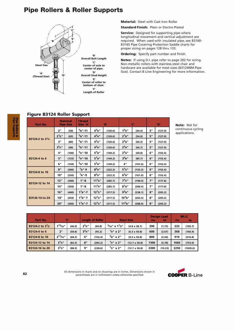
7/18/2019 PH Pipe Hanger Catalog
http://slidepdf.com/reader/full/ph-pipe-hanger-catalog 84/224
Pipe Rollers & Roller Supports
Material: Steel with Cast Iron Roller
Standard Finish: Plain or Electro-Plated
Service: Designed for supporting pipe wherelongitudinal movement and vertical adjustment arerequired. When used with insulated pipe, see B3160-B3165 Pipe Covering Protection Saddle charts forproper sizing on pages 128 thru 133.
Ordering: Specify part number and finish.Notes: If using D.I. pipe refer to page 202 for sizing.Non-metallic rollers with stainless steel chair andhardware are available for most sizes (B3124NM-PipeSize). Contact B-Line Engineering for more information.
Figure B3124 Roller Support
'B'
'C'
Steel Size
'A'(Thread Size)
'E'
'D'
'B'Overall Bolt Length
'C'Center of axle to
center of pipe.'D'
Overall Stud Height'E'
Center of roller tobottom of chair.
'F'Length of Roller
Nominal ThreadPart No. Pipe Size Size 'A' 'B' 'C' 'D'
2" (50) 5 / 8"-11 4 3 / 4" (120.6) 13 / 4" (44.4) 5" (127.0)
21 / 2" (65) 5 / 8"-11 4 3 / 4" (120.6) 21 / 8" (54.0) 5" (127.0)B3124-2 to 3 1 / 2
3" (80) 5 / 8"-11 4 3 / 4" (120.6) 23 / 8" (60.3) 5" (127.0)
31 / 2" (90) 5 / 8"-11 4 3 / 4" (120.6) 25 / 8" (66.7) 5" (127.0)
4" (100) 3 / 4"-10 5 7 / 8" (149.2) 23 / 4" (69.8) 6" (152.4)
B3124-4 to 6 5" (125) 3 / 4"-10 5 7 / 8" (149.2) 33 / 8" (85.7) 6" (152.4)
6" (150) 3 / 4"-10 5 7 / 8" (149.2) 4" (101.6) 6" (152.4)
B3124-8 to 108" (200) 7 / 8"-9 8 3 / 4" (222.2) 51 / 4" (133.3) 6" (152.4)
10" (250) 7 / 8"-9 8 3 / 4" (222.2) 63 / 8" (161.9) 6" (152.4)
B3124-12 to 1412" (300) 1"-8 11 1 / 4" (285.7) 71 / 2" (190.5) 7" (177.8)
14" (350) 1"-8 11 1 / 4" (285.7) 81 / 8" (206.4) 7" (177.8)
16" (400) 11 / 8"-7 12 1 / 2" (317.5) 93 / 8" (238.1) 8" (203.2)
B3124-16 to 20 18" (450) 11 / 8"-7 12 1 / 2" (317.5) 10 3 / 8" (263.5) 8" (203.2)
20" (500) 11 / 8"-7 12 1 / 2" (317.5) 11 3 / 8" (288.9) 8" (203.2)
Design Load Wt./CPart No. 'E' Length of Roller Steel Size Lbs. kN Lbs. kg
B3124-2 to 3 1 / 2 113 / 16 " (46.0) 23 / 4" (69.8) 3 / 16 " x 1 1 / 2" (4.8 x 38.1) 390 (1.73) 233 (105.7)
B3124-4 to 6 2" (50.8) 33 / 4" (95.2) 1 / 4" x 2" (6.3 x 50.8) 600 (2.67) 368 (166.9)
B3124-8 to 10 2 11 / 16 " (68.3) 6" (152.4) 3 / 8" x 2" (9.5 x 50.8) 800 (3.56) 919 (416.8)
B3124-12 to 14 3 1 / 4" (82.5) 8" (203.2) 1 / 2" x 2" (12.7 x 50.8) 1300 (5.78) 1660 (753.0)
B3124-16 to 20 3 1 / 2" (88.9) 9" (228.6) 1 / 2" x 2" (12.7 x 50.8) 2300 (10.23) 2250 (1020.6)
82All dimensions in charts and on drawings are in inches. Dimensions shown in
parentheses are in millimeters unless otherwise specified.
Note: Not forcontinuous cyclingapplications.
P i peR ol l er s &
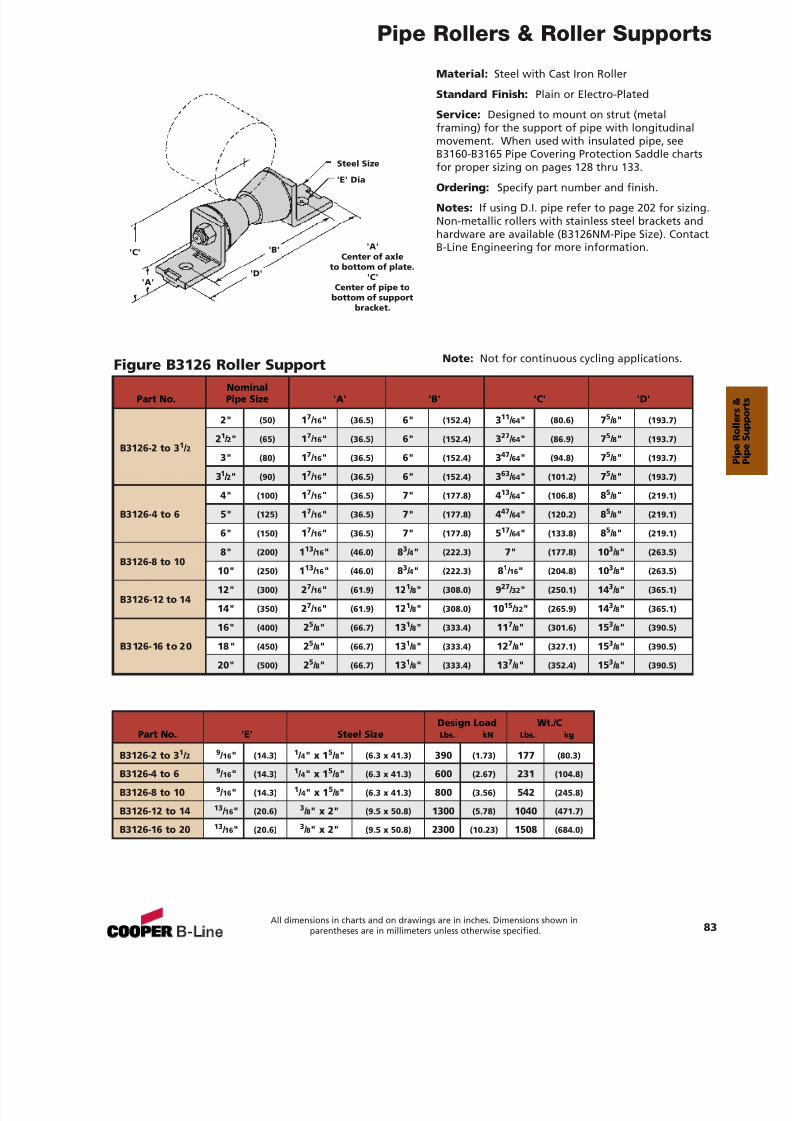
7/18/2019 PH Pipe Hanger Catalog
http://slidepdf.com/reader/full/ph-pipe-hanger-catalog 85/224
Pipe Rollers & Roller Supports
Material: Steel with Cast Iron Roller
Standard Finish: Plain or Electro-Plated
Service: Designed to mount on strut (metalframing) for the support of pipe with longitudinalmovement. When used with insulated pipe, seeB3160-B3165 Pipe Covering Protection Saddle chartsfor proper sizing on pages 128 thru 133.
Ordering: Specify part number and finish.
Notes: If using D.I. pipe refer to page 202 for sizing.Non-metallic rollers with stainless steel brackets andhardware are available (B3126NM-Pipe Size). ContactB-Line Engineering for more information.
Figure B3126 Roller Support
'A'Center of axle
to bottom of plate.'C'
Center of pipe tobottom of support
bracket.
Steel Size
'E' Dia
'B'
'D'
'C'
'A'
Design Load Wt./CPart No. 'E' Steel Size Lbs. kN Lbs. kg
B3126-2 to 3 1 / 2 9 / 16 " (14.3) 1 / 4" x 1 5 / 8" (6.3 x 41.3) 390 (1.73) 177 (80.3)
B3126-4 to 6 9 / 16 " (14.3) 1 / 4" x 1 5 / 8" (6.3 x 41.3) 600 (2.67) 231 (104.8)
B3126-8 to 10 9 / 16 " (14.3) 1 / 4" x 1 5 / 8" (6.3 x 41.3) 800 (3.56) 542 (245.8)
B3126-12 to 14 13 / 16 " (20.6) 3 / 8" x 2" (9.5 x 50.8) 1300 (5.78) 1040 (471.7)
B3126-16 to 20 13 / 16 " (20.6) 3 / 8" x 2" (9.5 x 50.8) 2300 (10.23) 1508 (684.0)
NominalPart No. Pipe Size 'A' 'B' 'C' 'D'
2" (50) 17 / 16 " (36.5) 6" (152.4) 311 / 64 " (80.6) 75 / 8" (193.7)
21 / 2" (65) 17 / 16 " (36.5) 6" (152.4) 327 / 64 " (86.9) 75 / 8" (193.7)B3126-2 to 3 1 / 2
3" (80) 17 / 16 " (36.5) 6" (152.4) 347 / 64 " (94.8) 75 / 8" (193.7)
31 / 2" (90) 17 / 16 " (36.5) 6" (152.4) 363 / 64 " (101.2) 75 / 8" (193.7)
4" (100) 17 / 16 " (36.5) 7" (177.8) 413 / 64 " (106.8) 85 / 8" (219.1)
B3126-4 to 6 5" (125) 17 / 16 " (36.5) 7" (177.8) 447 / 64 " (120.2) 85 / 8" (219.1)
6" (150) 17 / 16 " (36.5) 7" (177.8) 517 / 64 " (133.8) 85 / 8" (219.1)
B3126-8 to 10 8" (200) 113
/ 16 " (46.0) 83
/ 4" (222.3) 7" (177.8) 103
/ 8" (263.5)10" (250) 113 / 16 " (46.0) 83 / 4" (222.3) 81 / 16 " (204.8) 10 3 / 8" (263.5)
B3126-12 to 1412" (300) 27 / 16 " (61.9) 12 1 / 8" (308.0) 927 / 32 " (250.1) 14 3 / 8" (365.1)
14" (350) 27 / 16 " (61.9) 12 1 / 8" (308.0) 10 15 / 32 " (265.9) 14 3 / 8" (365.1)
16" (400) 25 / 8" (66.7) 13 1 / 8" (333.4) 11 7 / 8" (301.6) 15 3 / 8" (390.5)
B3126-16 to 20 18" (450) 25 / 8" (66.7) 13 1 / 8" (333.4) 12 7 / 8" (327.1) 15 3 / 8" (390.5)
20" (500) 25 / 8" (66.7) 13 1 / 8" (333.4) 13 7 / 8" (352.4) 15 3 / 8" (390.5)
83All dimensions in charts and on drawings are in inches. Dimensions shown in
parentheses are in millimeters unless otherwise specified.
Note: Not for continuous cycling applications.
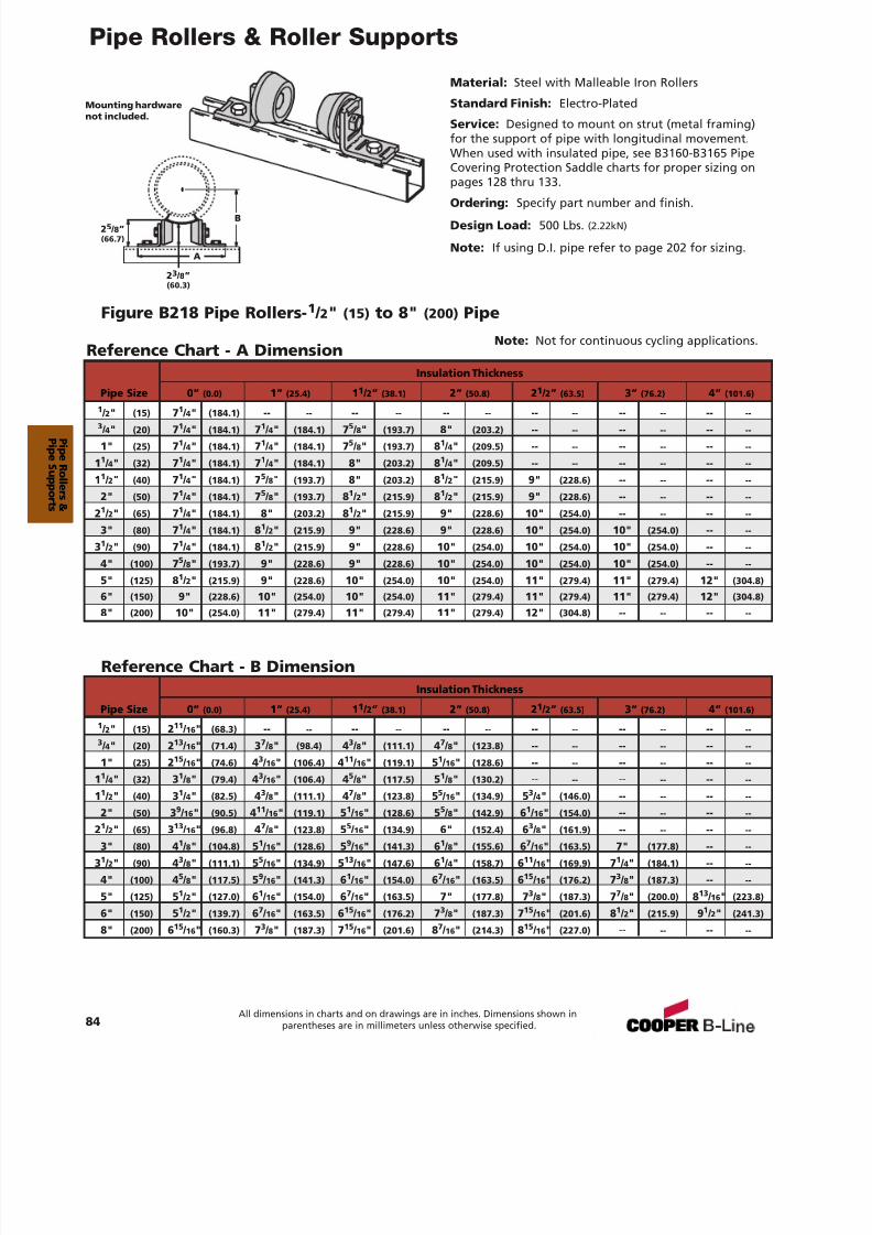
7/18/2019 PH Pipe Hanger Catalog
http://slidepdf.com/reader/full/ph-pipe-hanger-catalog 86/224
Pipe Rollers & Roller Supports
Material: Steel with Malleable Iron Rollers
Standard Finish: Electro-Plated
Service: Designed to mount on strut (metal framing)for the support of pipe with longitudinal movement.When used with insulated pipe, see B3160-B3165 PipeCovering Protection Saddle charts for proper sizing onpages 128 thru 133.
Ordering: Specify part number and finish.Design Load: 500 Lbs. (2.22kN)
Note: If using D.I. pipe refer to page 202 for sizing.
Figure B218 Pipe Rollers- 1 / 2" (15) to 8" (200) Pipe
Reference Chart - A Dimension
Mounting hardwarenot included.
84All dimensions in charts and on drawings are in inches. Dimensions shown in
parentheses are in millimeters unless otherwise specified.
Insulation Thickness
Pipe Size 0” (0.0) 1” (25.4) 11 / 2” (38.1) 2” (50.8) 21 / 2” (63.5) 3” (76.2) 4” (101.6)
1 / 2" (15) 71 / 4" (184.1) -- -- -- -- -- -- -- -- -- -- -- --3 / 4" (20) 71 / 4" (184.1) 71 / 4" (184.1) 75 / 8" (193.7) 8" (203.2) -- -- -- -- -- --
1" (25) 71 / 4" (184.1) 71 / 4" (184.1) 75 / 8" (193.7) 81 / 4" (209.5) -- -- -- -- -- --
11 / 4" (32) 71 / 4" (184.1) 71 / 4" (184.1) 8" (203.2) 81 / 4" (209.5) -- -- -- -- -- --
11 / 2" (40) 71 / 4" (184.1) 75 / 8" (193.7) 8" (203.2) 81 / 2" (215.9) 9" (228.6) -- -- -- --
2" (50) 71 / 4" (184.1) 75 / 8" (193.7) 81 / 2" (215.9) 81 / 2" (215.9) 9" (228.6) -- -- -- --
21 / 2" (65) 71 / 4" (184.1) 8" (203.2) 81 / 2" (215.9) 9" (228.6) 10" (254.0) -- -- -- --
3" (80) 71 / 4" (184.1) 81 / 2" (215.9) 9" (228.6) 9" (228.6) 10" (254.0) 10" (254.0) -- --
31 / 2" (90) 71 / 4" (184.1) 81 / 2" (215.9) 9" (228.6) 10" (254.0) 10" (254.0) 10" (254.0) -- --
4" (100) 75 / 8" (193.7) 9" (228.6) 9" (228.6) 10" (254.0) 10" (254.0) 10" (254.0) -- --
5" (125) 81 / 2" (215.9) 9" (228.6) 10" (254.0) 10" (254.0) 11" (279.4) 11" (279.4) 12" (304.8)
6" (150) 9" (228.6) 10" (254.0) 10" (254.0) 11" (279.4) 11" (279.4) 11" (279.4) 12" (304.8)
8" (200) 10" (254.0) 11" (279.4) 11" (279.4) 11" (279.4) 12" (304.8) -- -- -- --
Reference Chart - B DimensionInsulation Thickness
Pipe Size 0” (0.0) 1” (25.4) 11 / 2” (38.1) 2” (50.8) 21 / 2” (63.5) 3” (76.2) 4” (101.6)
1 / 2" (15) 211 / 16 " (68.3) -- -- -- -- -- -- -- -- -- -- -- --3 / 4" (20) 213 / 16 " (71.4) 37 / 8" (98.4) 43 / 8" (111.1) 47 / 8" (123.8) -- -- -- -- -- --
1" (25) 215 / 16 " (74.6) 43 / 16 " (106.4) 411 / 16 " (119.1) 51 / 16 " (128.6) -- -- -- -- -- --
11 / 4" (32) 31 / 8" (79.4) 43 / 16 " (106.4) 45 / 8" (117.5) 51 / 8" (130.2) -- -- -- -- -- --
11 / 2" (40) 31 / 4" (82.5) 43 / 8" (111.1) 47 / 8" (123.8) 55 / 16 " (134.9) 53 / 4" (146.0) -- -- -- --
2" (50) 39
/ 16 " (90.5) 411
/ 16 " (119.1) 51
/ 16 " (128.6) 55
/ 8" (142.9) 61
/ 16 " (154.0) -- -- -- --21 / 2" (65) 313 / 16 " (96.8) 47 / 8" (123.8) 55 / 16 " (134.9) 6" (152.4) 63 / 8" (161.9) -- -- -- --
3" (80) 41 / 8" (104.8) 51 / 16 " (128.6) 59 / 16 " (141.3) 61 / 8" (155.6) 67 / 16 " (163.5) 7" (177.8) -- --
31 / 2" (90) 43 / 8" (111.1) 55 / 16 " (134.9) 513 / 16 " (147.6) 61 / 4" (158.7) 611 / 16 " (169.9) 71 / 4" (184.1) -- --
4" (100) 45 / 8" (117.5) 59 / 16 " (141.3) 61 / 16 " (154.0) 67 / 16 " (163.5) 615 / 16 " (176.2) 73 / 8" (187.3) -- --
5" (125) 51 / 2" (127.0) 61 / 16 " (154.0) 67 / 16 " (163.5) 7" (177.8) 73 / 8" (187.3) 77 / 8" (200.0) 813 / 16 " (223.8)
6" (150) 51 / 2" (139.7) 67 / 16 " (163.5) 615 / 16 " (176.2) 73 / 8" (187.3) 715 / 16 " (201.6) 81 / 2" (215.9) 91 / 2" (241.3)
8" (200) 615 / 16 " (160.3) 73 / 8" (187.3) 715 / 16 " (201.6) 87 / 16 " (214.3) 815 / 16 " (227.0) -- -- -- --
B
A
2 5 / 8”(66.7)
2 3 / 8”(60.3)
Note: Not for continuous cycling applications.
P i peR ol l er s &
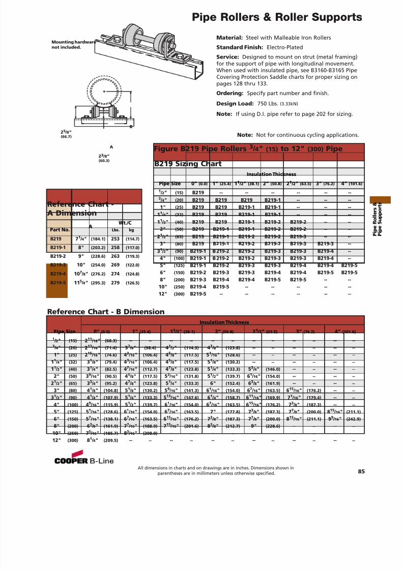
7/18/2019 PH Pipe Hanger Catalog
http://slidepdf.com/reader/full/ph-pipe-hanger-catalog 87/224
Reference Chart -A Dimension
Pipe Rollers & Roller Supports
85All dimensions in charts and on drawings are in inches. Dimensions shown in
parentheses are in millimeters unless otherwise specified.
Material: Steel with Malleable Iron Rollers
Standard Finish: Electro-Plated
Service: Designed to mount on strut (metal framing)for the support of pipe with longitudinal movement.When used with insulated pipe, see B3160-B3165 PipeCovering Protection Saddle charts for proper sizing onpages 128 thru 133.
Ordering: Specify part number and finish.Design Load: 750 Lbs. (3.33kN)
Note: If using D.I. pipe refer to page 202 for sizing.
Figure B219 Pipe Rollers 3 / 4" (15) to 12" (300) Pipe
Mounting hardwarenot included.
AWt./C
Part No. Lbs. kg
B219 71 / 4" (184.1) 253 (114.7)
B219-1 8" (203.2) 258 (117.0)
B219-2 9" (228.6) 263 (119.3)
B219-3 10" (254.0) 269 (122.0)
B219-4 10 7 / 8" (276.2) 274 (124.8)
B219-5 11 5 / 8" (295.3) 279 (126.5)
Reference Chart - B DimensionInsulation Thickness
Pipe Size 0” (0.0) 1” (25.4) 11 / 2” (38.1) 2” (50.8) 21 / 2” (63.5) 3” (76.2) 4” (101.6)
1 / 2" (15) 211 / 16 " (68.3) -- -- -- -- -- -- -- -- -- -- -- --3 / 4" (20) 213 / 16 " (71.4) 37 / 8" (98.4) 41 / 2" (114.3) 47 / 8" (123.8) -- -- -- -- -- --
1" (25) 215 / 16 " (74.6) 43 / 16 " (106.4) 45 / 8" (117.5) 51 / 16 " (128.6) -- -- -- -- -- --
11 / 4" (32) 31 / 8" (79.4) 43 / 16 " (106.4) 45 / 8" (117.5) 51 / 8" (130.2) -- -- -- -- -- --
11 / 2" (40) 31 / 4" (82.5) 47 / 16 " (112.7) 47 / 8" (123.8) 51 / 4" (133.3) 53 / 4" (146.0) -- -- -- --
2" (50) 39 / 16 " (90.5) 4
5 / 8" (117.5) 5
3 / 16 " (131.8) 5
1 / 2" (139.7) 6
1 / 16 " (154.0) -- -- -- --
21 / 2" (65) 33 / 4" (95.2) 47 / 8" (123.8) 51 / 4" (133.3) 6" (152.4) 63 / 8" (161.9) -- -- -- --
3" (80) 41 / 8" (104.8) 51 / 8" (130.2) 59 / 16 " (141.3) 61 / 16 " (154.0) 67 / 16 " (163.5) 615 / 16 " (176.2) -- --
31 / 2" (90) 41 / 4" (107.9) 51 / 4" (133.3) 513 / 16 " (147.6) 61 / 4" (158.7) 611 / 16 " (169.9) 71 / 16 " (179.4) -- --
4" (100) 49 / 16 " (115.9) 51 / 2" (139.7) 61 / 16 " (154.0) 67 / 16 " (163.5) 615 / 16 " (176.2) 73 / 8" (187.3) -- --
5" (125) 51 / 16 " (128.6) 61 / 16 " (154.0) 67 / 16 " (163.5) 7" (177.8) 73 / 8" (187.3) 77 / 8" (200.0) 815 / 16 " (211.1)
6" (150) 57 / 16 " (138.1) 67 / 16 " (163.5) 615 / 16 " (176.2) 73 / 8" (187.3) 77 / 8" (200.0) 815 / 16 " (211.1) 99 / 16 " (242.9)
8" (200) 63 / 8" (161.9) 77 / 16 " (188.9) 715 / 16 " (201.6) 83 / 8" (212.7) 9" (228.6) -- -- -- --
10" (250) 75 / 16 " (185.7) 83 / 16 " (208.0) -- -- -- -- -- -- -- -- -- --
12" (300) 81 / 4" (209.5) -- -- -- -- -- -- -- -- -- -- -- --
B219 Sizing ChartInsulation Thickness
Pipe Size 0” (0.0) 1” (25.4) 11 / 2” (38.1) 2” (50.8) 21 / 2” (63.5) 3” (76.2) 4” (101.6)
1 / 2" (15) B219 -- -- -- -- -- --3 / 4" (20) B219 B219 B219 B219-1 -- -- --1" (25) B219 B219 B219-1 B219-1 -- -- --
11 / 4" (32) B219 B219 B219-1 B219-1 -- -- --11 / 2" (40) B219 B219 B219-1 B219-2 B219-2 -- --
2" (50) B219 B219-1 B219-1 B219-2 B219-2 -- --21 / 2" (65) B219 B219-1 B219-2 B219-2 B219-3 -- --
3" (80) B219 B219-1 B219-2 B219-2 B219-3 B219-3 --31 / 2" (90) B219-1 B 219-2 B219-2 B219-3 B219-3 B219-4 --
4" (100) B219-1 B 219-2 B219-2 B219-3 B219-3 B219-4 --5" (125) B219-1 B219-2 B219-3 B219-3 B219-4 B219-4 B219-56" (150) B219-2 B219-3 B219-3 B219-4 B219-4 B219-5 B219-58" (200) B219-3 B219-4 B219-4 B219-5 B219-5 -- --
10" (250) B219-4 B219-5 -- -- -- -- --12" (300) B219-5 -- -- -- -- -- --
B
A
2 5 / 8”(66.7)
23 / 8”(60.3)
Note: Not for continuous cycling applications.
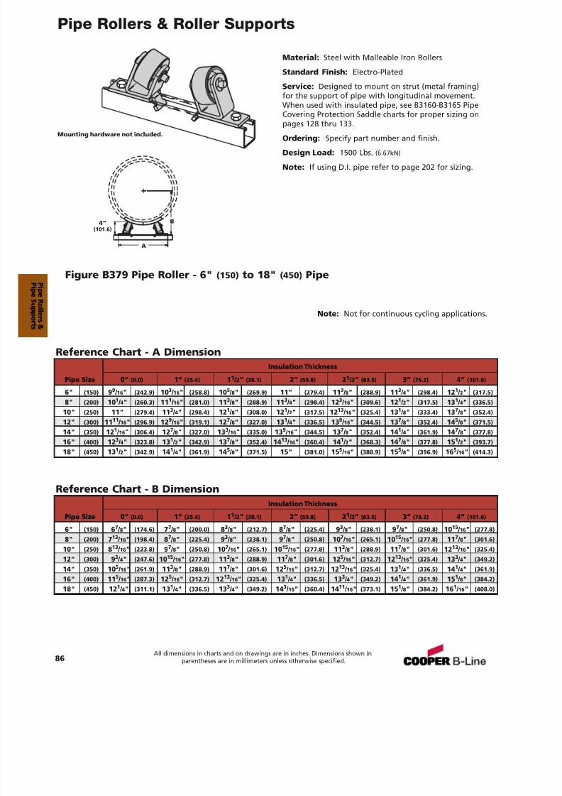
7/18/2019 PH Pipe Hanger Catalog
http://slidepdf.com/reader/full/ph-pipe-hanger-catalog 88/224
Pipe Rollers & Roller Supports
86All dimensions in charts and on drawings are in inches. Dimensions shown in
parentheses are in millimeters unless otherwise specified.
Material: Steel with Malleable Iron Rollers
Standard Finish: Electro-Plated
Service: Designed to mount on strut (metal framing)for the support of pipe with longitudinal movement.When used with insulated pipe, see B3160-B3165 PipeCovering Protection Saddle charts for proper sizing onpages 128 thru 133.
Ordering: Specify part number and finish.
Design Load: 1500 Lbs. (6.67kN)
Note: If using D.I. pipe refer to page 202 for sizing.
Figure B379 Pipe Roller - 6" (150) to 18" (450) Pipe
Mounting hardware not included.
Reference Chart - B DimensionInsulation Thickness
Pipe Size 0” (0.0) 1” (25.4) 11 / 2” (38.1) 2” (50.8) 21 / 2” (63.5) 3” (76.2) 4” (101.6)
6" (150) 67 / 8" (174.6) 77 / 8" (200.0) 83 / 8" (212.7) 87 / 8" (225.4) 93 / 8" (238.1) 97 / 8" (250.8) 10 15 / 16 " (277.8)
8" (200) 713 / 16 " (198.4) 87 / 8" (225.4) 93 / 8" (238.1) 97 / 8" (250.8) 10 7 / 16 " (265.1) 10 15 / 16 " (277.8) 11 7 / 8" (301.6)
10" (250) 813 / 16 " (223.8) 97 / 8" (250.8) 10 7 / 16 " (265.1) 10 15 / 16 " (277.8) 11 3 / 8" (288.9) 11 7 / 8" (301.6) 12 13 / 16 " (325.4)
12" (300) 93 / 4" (247.6) 10 15 / 16 " (277.8) 11 3 / 8" (288.9) 11 7 / 8" (301.6) 12 5 / 16 " (312.7) 12 13 / 16 " (325.4) 13 3 / 4" (349.2)
14" (350) 10 5 / 16 " (261.9) 11 3 / 8" (288.9) 11 7 / 8" (301.6) 12 5 / 16 " (312.7) 12 13 / 16 " (325.4) 13 1 / 4" (336.5) 14 1 / 4" (361.9)
16" (400) 11 5 / 16 " (287.3) 12 5 / 16 " (312.7) 12 13 / 16 " (325.4) 13 1 / 4" (336.5) 13 3 / 4" (349.2) 14 1 / 4" (361.9) 15 1 / 8" (384.2)
18" (450) 12 1 / 4" (311.1) 13 1 / 4" (336.5) 13 3 / 4" (349.2) 14 3 / 16 " (360.4) 14 11 / 16 " (373.1) 15 1 / 8" (384.2) 16 1 / 16 " (408.0)
Reference Chart - A DimensionInsulation Thickness
Pipe Size 0” (0.0) 1” (25.4) 11 / 2” (38.1) 2” (50.8) 21 / 2” (63.5) 3” (76.2) 4” (101.6)
6" (150) 99
/ 16 " (242.9) 103
/ 16 " (258.8) 105
/ 8" (269.9) 11" (279.4) 113
/ 8" (288.9) 113
/ 4" (298.4) 121
/ 2" (317.5)8" (200) 10 1 / 4" (260.3) 11 1 / 16 " (281.0) 11 3 / 8" (288.9) 11 3 / 4" (298.4) 12 3 / 16 " (309.6) 12 1 / 2" (317.5) 13 1 / 4" (336.5)
10" (250) 11" (279.4) 11 3 / 4" (298.4) 12 1 / 8" (308.0) 12 1 / 2" (317.5) 12 13 / 16 " (325.4) 13 1 / 8" (333.4) 13 7 / 8" (352.4)
12" (300) 11 11 / 16 " (296.9) 12 9 / 16 " (319.1) 12 7 / 8" (327.0) 13 1 / 4" (336.5) 13 9 / 16 " (344.5) 13 7 / 8" (352.4) 14 5 / 8" (371.5)
14" (350) 12 1 / 16 " (306.4) 12 7 / 8" (327.0) 13 3 / 16 " (335.0) 13 9 / 16 " (344.5) 13 7 / 8" (352.4) 14 1 / 4" (361.9) 14 7 / 8" (377.8)
16" (400) 12 3 / 4" (323.8) 13 1 / 2" (342.9) 13 7 / 8" (352.4) 14 13 / 16 " (360.4) 14 1 / 2" (368.3) 14 7 / 8" (377.8) 15 1 / 2" (393.7)
18" (450) 13 1 / 2" (342.9) 14 1 / 4" (361.9) 14 5 / 8" (371.5) 15" (381.0) 15 5 / 16 " (388.9) 15 5 / 8" (396.9) 16 5 / 16 " (414.3)
B
A
4”(101.6)
Note: Not for continuous cycling applications.
P i peR ol l er s &
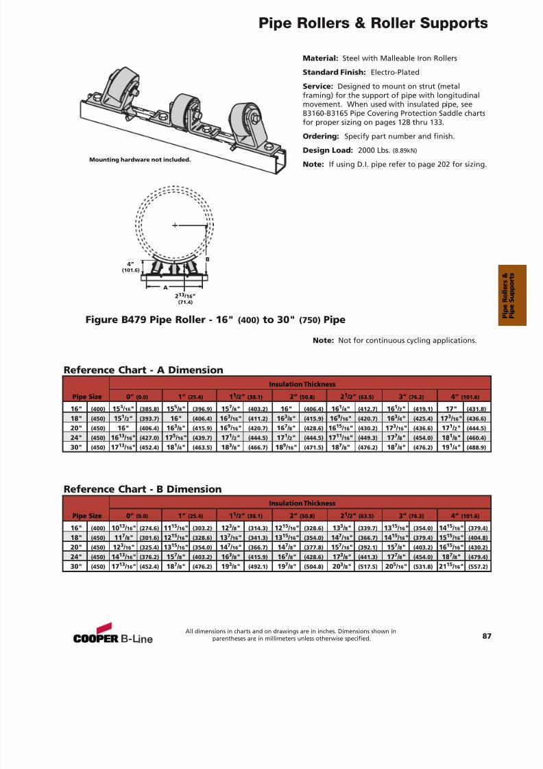
7/18/2019 PH Pipe Hanger Catalog
http://slidepdf.com/reader/full/ph-pipe-hanger-catalog 89/224
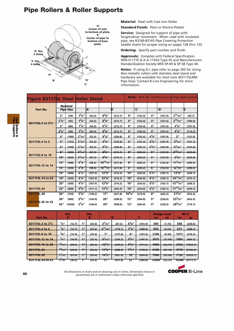
7/18/2019 PH Pipe Hanger Catalog
http://slidepdf.com/reader/full/ph-pipe-hanger-catalog 90/224
Pipe Rollers & Roller Supports
Material: Steel with Cast Iron Roller
Standard Finish: Plain or Electro-Plated
Service: Designed for support of pipe withlongitudinal movement. When used with insulatedpipe, see B3160-B3165 Pipe Covering ProtectionSaddle charts for proper sizing on pages 128 thru 133.
Ordering: Specify part number and finish.
Approvals: Complies with Federal SpecificationWW-H-171E & A-A-1192A Type 45 and ManufacturersStandardization Society MSS SP-69 & SP-58 Type 44.
Notes: If using D.I. pipe refer to page 202 for sizing.Non-metallic rollers with stainless steel stand andhardware are available for most sizes (B3117SLNM-Pipe Size). Contact B-Line Engineering for moreinformation.
Figure B3117SL Steel Roller Stand
'A'Center of axle
to bottom of plate.'E'
Center of pipe tobottom of base
plate.
'B' 'D'
'C'
'E'
'J''H'
'G' Dia.
2 Holes
'F' Dia.4 Holes
'A'
Nominal
Part No. Pipe Size 'A' 'B' 'C' 'D' 'E'
2" (50) 13 / 4" (44.4) 83 / 8" (212.7) 6" (152.4) 4" (101.6) 311 / 16 " (93.7)
21 / 2" (65) 13 / 4" (44.4) 83 / 8" (212.7) 6" (152.4) 4" (101.6) 315 / 16 " (100.0)B3117SL-2 to 3 1 / 2
3" (80) 13 / 4" (44.4) 83 / 8" (212.7) 6" (152.4) 4" (101.6) 41 / 4" (107.9)
31 / 2" (90) 13 / 4" (44.4) 83 / 8" (212.7) 6" (152.4) 4" (101.6) 41 / 2" (114.3)
4" (100) 21 / 16 " (52.4) 97 / 8" (250.8) 6" (152.4) 41 / 4" (107.9) 5" (127.0)
B3117SL-4 to 6 5" (125) 21 / 16 " (52.4) 97 / 8" (250.8) 6" (152.4) 41 / 4" (107.9) 59 / 16 " (141.3)
6" (150) 21 / 16 " (52.4) 97 / 8" (250.8) 6" (152.4) 41 / 4" (107.9) 61 / 16 " (154.0)
B3117SL-8 to 108" (200) 37 / 16 " (87.3) 85 / 8" (219.1) 8" (203.2) 5" (127.0) 813 / 16 " (223.8)
10" (250) 37 / 16 " (87.3) 85 / 8" (219.1) 8" (203.2) 5" (127.0) 97 / 8" (250.8)
B3117SL-12 to 1412" (300) 37 / 8" (98.4) 10 15 / 16 " (277.8) 8" (203.2) 6" (152.4) 11 7 / 16 " (290.5)
14" (350) 37 / 8" (98.4) 10 15 / 16 " (277.8) 8" (203.2) 6" (152.4) 12 1 / 16 " (306.4)
16" (400) 41 / 4" (107.9) 12 3 / 8" (314.3) 10" (254.0) 61 / 2" (165.1) 13 5 / 8" (346.1)
B3117SL-16 to 20 18" (450) 41 / 4" (107.9) 12 3 / 8" (314.3) 10" (254.0) 61 / 2" (165.1) 14 11 / 16 " (373.1)
20" (500) 41 / 4" (107.9) 12 3 / 8" (314.3) 10" (254.0) 61 / 2" (165.1) 15 11 / 16 " (398.5)
B3117SL-24 24" (600) 43 / 8" (111.1) 13 1 / 2" (342.9) 10" (254.0) 61 / 2" (165.1) 17 11 / 16 " (449.3)
B3117SL-30 30" (750) 51 / 8" (130.2) 17" (431.8) 10 3 / 4" (273.0) 8" (203.2) 21 3 / 4" (552.4)
B3117SL-36 to 4236" (900) 53 / 4" (146.0) 20" (508.0) 12" (304.8) 9" (228.6) 25 5 / 16 " (642.9)
42" (1050) 53 / 4" (146.0) 20" (508.0) 12" (304.8) 9" (228.6) 28 5 / 16 " (719.1)
Dia. Dia. Design Load Wt./C
Part No. 'F' 'G' 'H' 'J'Lbs. kN Lbs. kg
B3117SL-2 to 3 1 / 2 1 / 2" (12.7) 1" (25.4) 37 / 16 " (87.3) 63 / 8" (161.9) 390 (1.73) 508 (230.4)
B3117SL-4 to 6 1 / 2" (12.7) 1" (25.4) 411 / 16 " (119.1) 77 / 8" (200.0) 950 (4.22) 631 (286.2)
B3117SL-8 to 10 5 / 8" (15.9) 1" (25.4) 7" (177.8) 4" (101.6) 2100 (9.34) 1271 (576.5)
B3117SL-12 to 14 3 / 4" (19.0) 1" (25.4) 91 / 16 " (230.2) 53 / 4" (146.0) 3075 (13.68) 1994 (904.5)
B3117SL-16 to 20 13 / 16 " (20.6) 1" (25.4) 10 1 / 4" (260.3) 63 / 4" (171.4) 4980 (22.15) 3423 (1552.7)
B3117SL-24 13 / 16 " (20.6) 1" (25.4) 11 3 / 8" (288.9) 71 / 2" (190.5) 6100 (27.13) 4710 (2136.4)
B3117SL-30 1 1 / 16 " (27.0) 1" (25.4) 14 1 / 4" (361.9) 10" (254.0) 7500 (33.36) 7132 (3235.1)
B3117SL-36 to 42 1 3 / 16 " (30.2) 1" (25.4) 17" (431.8) 12" (304.8) 12000 (53.37) 10386 (4711.1)
88All dimensions in charts and on drawings are in inches. Dimensions shown in
parentheses are in millimeters unless otherwise specified.
Note: Not for continuous cycling applications.
P i peR ol l er s &
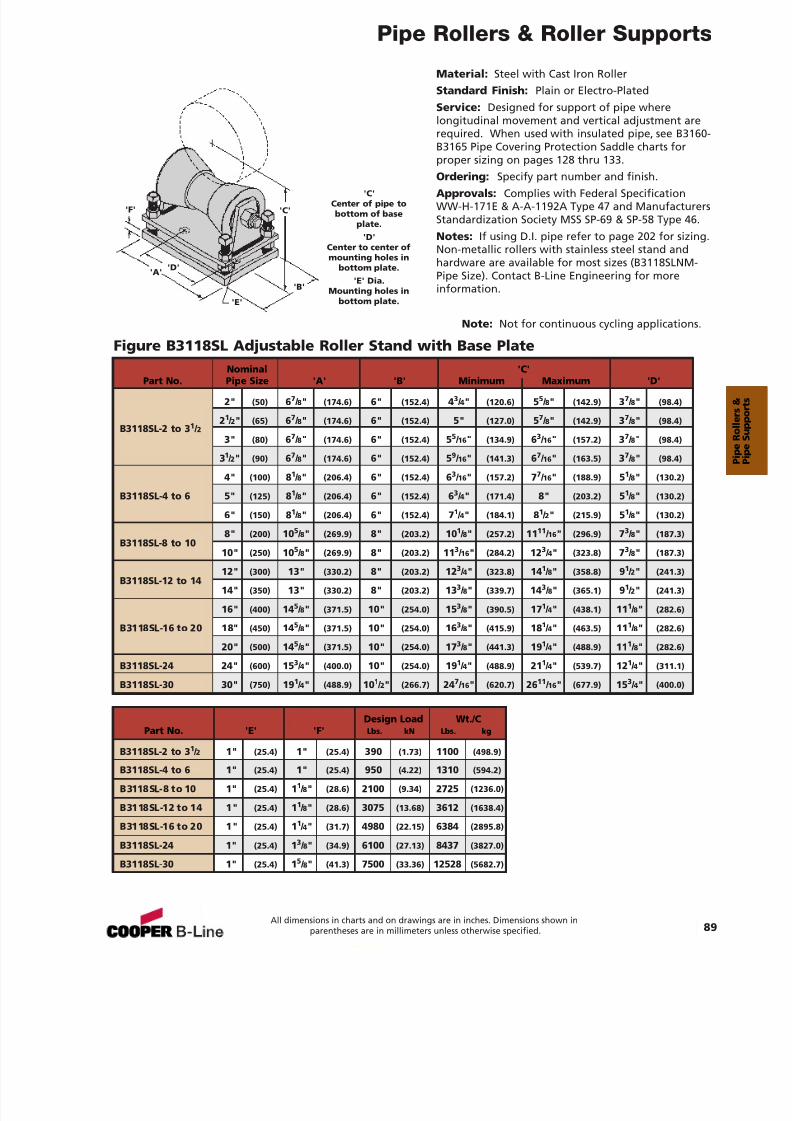
7/18/2019 PH Pipe Hanger Catalog
http://slidepdf.com/reader/full/ph-pipe-hanger-catalog 91/224
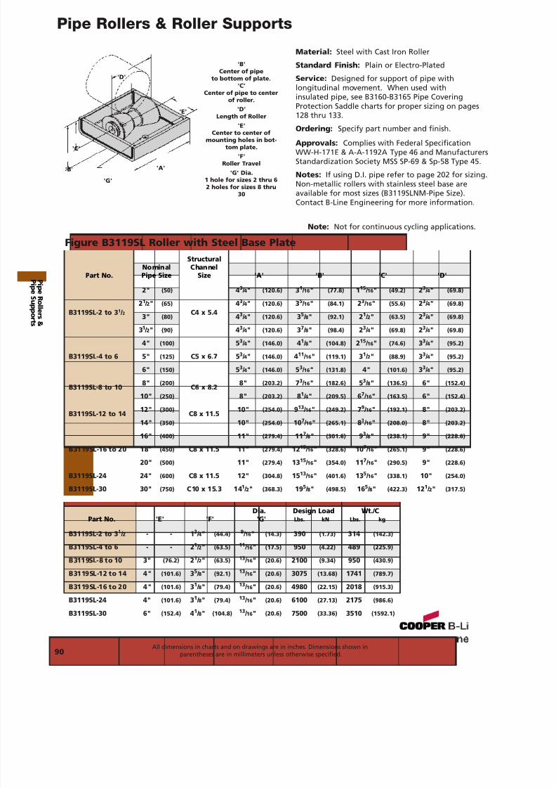
7/18/2019 PH Pipe Hanger Catalog
http://slidepdf.com/reader/full/ph-pipe-hanger-catalog 92/224
Pipe Rollers & Roller Supports
Material: Steel with Cast Iron Roller
Standard Finish: Plain or Electro-Plated
Service: Designed for support of pipe withlongitudinal movement. When used withinsulated pipe, see B3160-B3165 Pipe CoveringProtection Saddle charts for proper sizing on pages128 thru 133.
Ordering: Specify part number and finish.Approvals: Complies with Federal SpecificationWW-H-171E & A-A-1192A Type 46 and ManufacturersStandardization Society MSS SP-69 & Sp-58 Type 45.
Notes: If using D.I. pipe refer to page 202 for sizing.Non-metallic rollers with stainless steel base areavailable for most sizes (B3119SLNM-Pipe Size).Contact B-Line Engineering for more information.
Figure B3119SL Roller with Steel Base Plate
'B'Center of pipe
to bottom of plate.'C'
Center of pipe to centerof roller.
'D'Length of Roller
'E'Center to center of
mounting holes in bot-tom plate.
'F'Roller Travel
'G' Dia.1 hole for sizes 2 thru 62 holes for sizes 8 thru
30
'B'
'D'
'E'
'C'
'A'
'G'
StructuralNominal ChannelPart No. Pipe Size Size 'A' 'B' 'C' 'D'
2" (50) 43 / 4" (120.6) 31 / 16 " (77.8) 115 / 16 " (49.2) 23 / 4" (69.8)
21 / 2" (65) 43 / 4" (120.6) 35 / 16 " (84.1) 23 / 16 " (55.6) 23 / 4" (69.8)B3119SL-2 to 3 1 / 2 3" (80)
C4 x 5.4 43 / 4" (120.6) 35 / 8" (92.1) 21 / 2" (63.5) 23 / 4" (69.8)
31 / 2" (90) 43 / 4" (120.6) 37 / 8" (98.4) 23 / 4" (69.8) 23 / 4" (69.8)
4" (100) 53 / 4" (146.0) 41 / 8" (104.8) 215 / 16 " (74.6) 33 / 4" (95.2)
B3119SL-4 to 6 5" (125) C5 x 6.7 5 3 / 4" (146.0) 411 / 16 " (119.1) 31 / 2" (88.9) 33 / 4" (95.2)
6" (150) 53 / 4" (146.0) 53 / 16 " (131.8) 4" (101.6) 33 / 4" (95.2)
B3119SL-8 to 10 8" (200)C6 x 8.2 8" (203.2) 73 / 16 " (182.6) 53 / 8" (136.5) 6" (152.4)
10" (250) 8" (203.2) 81 / 4" (209.5) 67 / 16 " (163.5) 6" (152.4)
B3119SL-12 to 14 12" (300)C8 x 11.5 10" (254.0) 913 / 16 " (249.2) 79 / 16 " (192.1) 8" (203.2)
14" (350) 10" (254.0) 10 7 / 16 " (265.1) 83 / 16 " (208.0) 8" (203.2)
16" (400) 11" (279.4) 11 7 / 8" (301.6) 93 / 8" (238.1) 9" (228.6)
B3119SL-16 to 20 18" (450) C8 x 11.5 11" (279.4) 12 15 / 16 " (328.6) 10 7 / 16 " (265.1) 9" (228.6)
20" (500) 11" (279.4) 13 15 / 16 " (354.0) 11 7 / 16 " (290.5) 9" (228.6)
B3119SL-24 24" (600) C8 x 11.5 12" (304.8) 15 13 / 16 " (401.6) 13 5 / 16 " (338.1) 10" (254.0)
B3119SL-30 30" (750) C10 x 15.3 14 1 / 2" (368.3) 19 5 / 8" (498.5) 16 5 / 8" (422.3) 12 1 / 2" (317.5)
Dia. Design Load Wt./C
Part No. 'E' 'F' 'G' Lbs. kN Lbs. kg
B3119SL-2 to 3 1 / 2 - - 1 3 / 4" (44.4) 9 / 16 " (14.3) 390 (1.73) 314 (142.3)
B3119SL-4 to 6 - - 2 1 / 2" (63.5) 11 / 16 " (17.5) 950 (4.22) 489 (225.9)
B3119SL-8 to 10 3" (76.2) 21 / 2" (63.5) 13 / 16 " (20.6) 2100 (9.34) 950 (430.9)
B3119SL-12 to 14 4" (101.6) 35 / 8" (92.1) 13 / 16 " (20.6) 3075 (13.68) 1741 (789.7)
B3119SL-16 to 20 4" (101.6) 31 / 8" (79.4) 13 / 16 " (20.6) 4980 (22.15) 2018 (915.3)
B3119SL-24 4" (101.6) 31 / 8" (79.4) 13 / 16 " (20.6) 6100 (27.13) 2175 (986.6)
B3119SL-30 6" (152.4) 41 / 8" (104.8) 13 / 16 " (20.6) 7500 (33.36) 3510 (1592.1)
90All dimensions in charts and on drawings are in inches. Dimensions shown in
parentheses are in millimeters unless otherwise specified.
Note: Not for continuous cycling applications.
P i peR ol l er s &
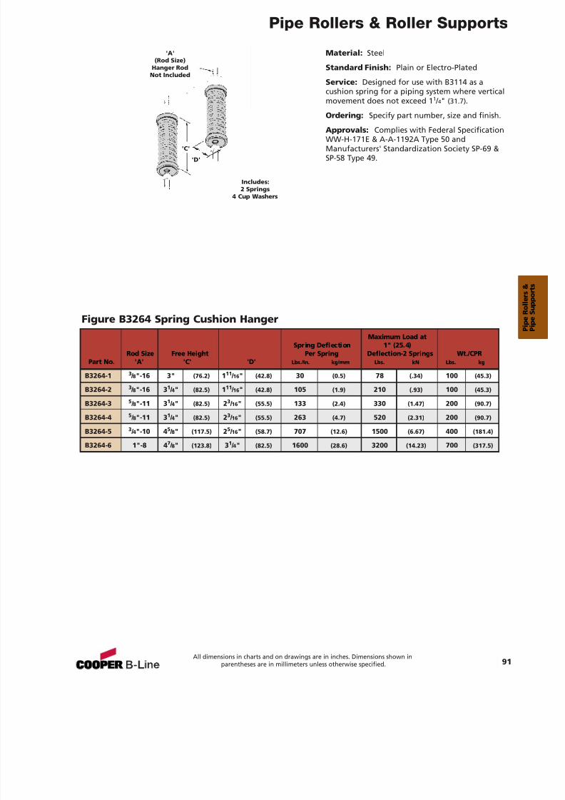
7/18/2019 PH Pipe Hanger Catalog
http://slidepdf.com/reader/full/ph-pipe-hanger-catalog 93/224
Pipe Rollers & Roller Supports
91All dimensions in charts and on drawings are in inches. Dimensions shown in
parentheses are in millimeters unless otherwise specified.
Material: Steel
Standard Finish: Plain or Electro-Plated
Service: Designed for use with B3114 as acushion spring for a piping system where verticalmovement does not exceed 1 1 / 4" (31.7) .
Ordering: Specify part number, size and finish.
Approvals: Complies with Federal SpecificationWW-H-171E & A-A-1192A Type 50 andManufacturers' Standardization Society SP-69 &SP-58 Type 49.
Figure B3264 Spring Cushion Hanger
'A'(Rod Size)
Hanger RodNot Included
Includes:2 Springs
4 Cup Washers
Maximum Load atSpring Deflection 1" (25.4)
Rod Size Free Height Per Spring Deflection-2 Springs Wt./CPRPart No. 'A' 'C' 'D' Lbs./In. kg/mm Lbs. kN Lbs. kg
B3264-1 3 / 8"-16 3" (76.2) 111 / 16 " (42.8) 30 (0.5) 78 (.34) 100 (45.3)
B3264-2 3 / 8"-16 3 1 / 4" (82.5) 111 / 16 " (42.8) 105 (1.9) 210 (.93) 100 (45.3)
B3264-3 5 / 8"-11 3 1 / 4" (82.5) 23 / 16 " (55.5) 133 (2.4) 330 (1.47) 200 (90.7)
B3264-4 5 / 8"-11 3 1 / 4" (82.5) 23 / 16 " (55.5) 263 (4.7) 520 (2.31) 200 (90.7)
B3264-5 3 / 4"-10 4 5 / 8" (117.5) 25 / 16 " (58.7) 707 (12.6) 1500 (6.67) 400 (181.4)
B3264-6 1"-8 4 7 / 8" (123.8) 31 / 4" (82.5) 1600 (28.6) 3200 (14.23) 700 (317.5)
'C'
'D'
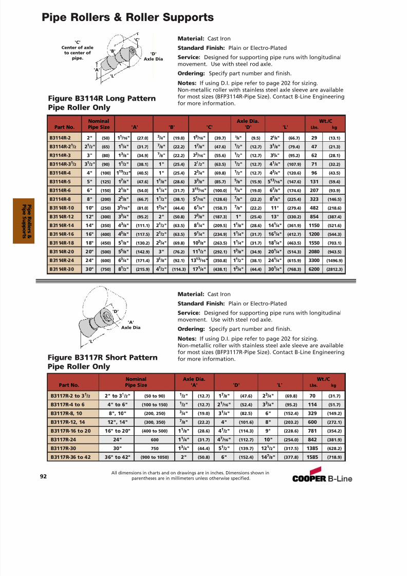
7/18/2019 PH Pipe Hanger Catalog
http://slidepdf.com/reader/full/ph-pipe-hanger-catalog 94/224
Pipe Rollers & Roller Supports
92All dimensions in charts and on drawings are in inches. Dimensions shown in
parentheses are in millimeters unless otherwise specified.
Material: Cast Iron
Standard Finish: Plain or Electro-Plated
Service: Designed for supporting pipe runs with longitudinalmovement. Use with steel rod axle.
Ordering: Specify part number and finish.
Notes: If using D.I. pipe refer to page 202 for sizing.Non-metallic roller with stainless steel axle sleeve are availablefor most sizes (BFP3114R-Pipe Size). Contact B-Line Engineeringfor more information.
Figure B3114R Long PatternPipe Roller Only
Material: Cast Iron
Standard Finish: Plain or Electro-Plated
Service: Designed for supporting pipe runs with longitudinalmovement. Use with steel rod axle.
Ordering: Specify part number and finish.
Notes: If using D.I. pipe refer to page 202 for sizing.Non-metallic roller with stainless steel axle sleeve are availablefor most sizes (BFP3117R-Pipe Size). Contact B-Line Engineeringfor more information.Figure B3117R Short Pattern
Pipe Roller Only
'D'Axle Dia
'B'
'L'
'A'Axle Dia
'L'
'D'
'C''C'Center of axle
to center ofpipe.
'A'
Nominal Axle Dia. Wt./CPart No. Pipe Size 'A' 'D' 'L' Lbs. kg
B3117R-2 to 3 1 / 2 2" to 3 1 / 2" (50 to 90) 1 / 2" (12.7) 17 / 8" (47.6) 23 / 4" (69.8) 70 (31.7)
B3117R-4 to 6 4" to 6" (100 to 150) 1 / 2" (12.7) 21 / 16 " (52.4) 33 / 4" (95.2) 114 (51.7)
B3117R-8, 10 8", 10" (200, 250) 3 / 4" (19.0) 31 / 4" (82.5) 6" (152.4) 329 (149.2)
B3117R-12, 14 12", 14" (300, 350) 7 / 8" (22.2) 4" (101.6) 8" (203.2) 600 (272.1)
B3117R-16 to 20 16" to 20" (400 to 500) 11 / 8" (28.6) 41 / 2" (114.3) 9" (228.6) 781 (354.2)
B3117R-24 24" 600 11 / 4" (31.7) 47 / 16 " (112.7) 10" (254.0) 842 (381.9)
B3117R-30 30" 750 13 / 4" (44.4) 51 / 2" (139.7) 12 1 / 2" (317.5) 1385 (628.2)
B3117R-36 to 42 36" to 42" (900 to 1050) 2" (50.8) 6" (152.4) 14 7 / 8" (377.8) 1585 (718.9)
Nominal Axle Dia. Wt./CPart No. Pipe Size 'A' 'B' 'C' 'D' 'L' Lbs. kg
B3114R-2 2" (50) 11 / 16" (27.0) 3 / 4" (19.0) 19 / 16" (39.7) 3 / 8" (9.5) 25 / 8" (66.7) 29 (13.1)
B3114R-2 1 / 2 21 / 2" (65) 11 / 4" (31.7) 7 / 8" (22.2) 17 / 8" (47.6) 1 / 2" (12.7) 31 / 8" (79.4) 47 (21.3)
B3114R-3 3" (80) 13 / 8" (34.9) 7 / 8" (22.2) 23 / 16" (55.6) 1 / 2" (12.7) 33 / 4" (95.2) 62 (28.1)
B3114R-3 1 / 2 31 / 2" (90) 11 / 2" (38.1) 1" (25.4) 21 / 2" (63.5) 1 / 2" (12.7) 41 / 4" (107.9) 71 (32.2)
B3114R-4 4" (100) 119 / 32" (40.5) 1" (25.4) 23 / 4" (69.8) 1 / 2" (12.7) 43 / 4" (120.6) 96 (43.5)
B3114R-5 5" (125) 17 / 8" (47.6) 11 / 8" (28.6) 33 / 8" (85.7) 5 / 8" (15.9) 513 / 16" (147.6) 131 (59.4)
B3114R-6 6" (150) 21 / 8" (54.0) 11 / 4" (31.7) 315 / 16" (100.0) 3 / 4" (19.0) 67 / 8" (174.6) 207 (93.9)
B3114R-8 8" (200) 25 / 8" (66.7) 11 / 2" (38.1) 51 / 16" (128.6) 7 / 8" (22.2) 87 / 8" (225.4) 323 (146.5)
B3114R-10 10" (250) 33 / 16" (81.0) 13 / 4" (44.4) 61 / 4" (158.7) 7 / 8" (22.2) 11" (279.4) 482 (218.6)
B3114R-12 12" (300) 33 / 4" (95.2) 2" (50.8) 73 / 8" (187.3) 1" (25.4) 13" (330.2) 854 (387.4)
B3114R-14 14" (350) 43 / 8" (111.1) 21 / 2" (63.5) 81 / 4" (209.5) 11 / 8" (28.6) 14 1 / 4" (361.9) 1150 (521.6)
B3114R-16 16" (400) 45 / 8" (117.5) 21 / 2" (63.5) 91 / 4" (234.9) 11 / 4" (31.7) 16 1 / 4" (412.7) 1200 (544.3)
B3114R-18 18" (450) 51 / 8" (130.2) 23 / 4" (69.8) 103 / 8" (263.5) 11 / 4" (31.7) 18 1 / 4" (463.5) 1550 (703.1)
B3114R-20 20" (500) 55 / 8" (142.9) 3" (76.2) 11 1 / 2" (292.1) 13 / 8" (34.9) 20 1 / 4" (514.3) 2080 (943.5)
B3114R-24 24" (600) 63 / 4" (171.4) 35 / 8" (92.1) 1313 / 16" (350.8) 11 / 2" (38.1) 24 1 / 4" (615.9) 3300 (1496.9)
B3114R-30 30" (750) 81 / 2" (215.9) 41 / 2" (114.3) 17 1 / 4" (438.1) 13 / 4" (44.4) 30 1 / 4" (768.3) 6200 (2812.3)
P i peR ol l er s &
7/18/2019 PH Pipe Hanger Catalog
http://slidepdf.com/reader/full/ph-pipe-hanger-catalog 95/224
Pipe Rollers & Roller Supports
93All dimensions in charts and on drawings are in inches. Dimensions shown in
parentheses are in millimeters unless otherwise specified.
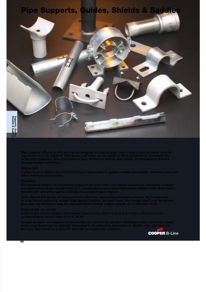
7/18/2019 PH Pipe Hanger Catalog
http://slidepdf.com/reader/full/ph-pipe-hanger-catalog 96/224
Pipe supports offered in this section are designed to support pipe from a base structure where verticaladjustment may be required. Pipe guides and slides are designed to allow longitudinal movement dueto thermal expansion and contraction of pipe. Protection shields and saddles are designed to preventdamage to pipe insulation.
MaterialsCarbon Steel is used in the manufacturing of pipe supports, guides, shields and saddles. Stainless Steel andother materials are available.
FinishesThe standard finishes for mechanical supports are plain steel (oil coated) sometimes referred to as blackand Electro-Plated Zinc (ASTM B 633 SC3). Hot-Dip Galvanized After Fabrication (ASTM A 123), Red Primer,
Dura-Green®
and other special coatings are available upon request.Note: Due to the design of some products, (threads, connecting hardware, swivels, etc.) items mayor may not be uniformly coated with special finishes. In some cases, the hanger itself may be coated,however, the hardware may be supplied Electro-Plated, Copper plated, or in Stainless Steel.
Approvals (as noted)Items in this section comply with Federal Specification WW-H-171E & A-A-1192A or ManufacturersStandardization Society MSS SP-69 & SP-58.
All pipe hangers and supports in this section are sized to fit schedule 40/80 pipe unless otherwise noted.Some steel items may be specially fabricated to fit other pipe diameters i.e. ductile iron, cast iron, etc.See pipe data charts on pages 201 thru 206 for proper size selection.
94
Pipe Supports, Guides, Shields & Saddles
S uppor t s ,Gui d es ,
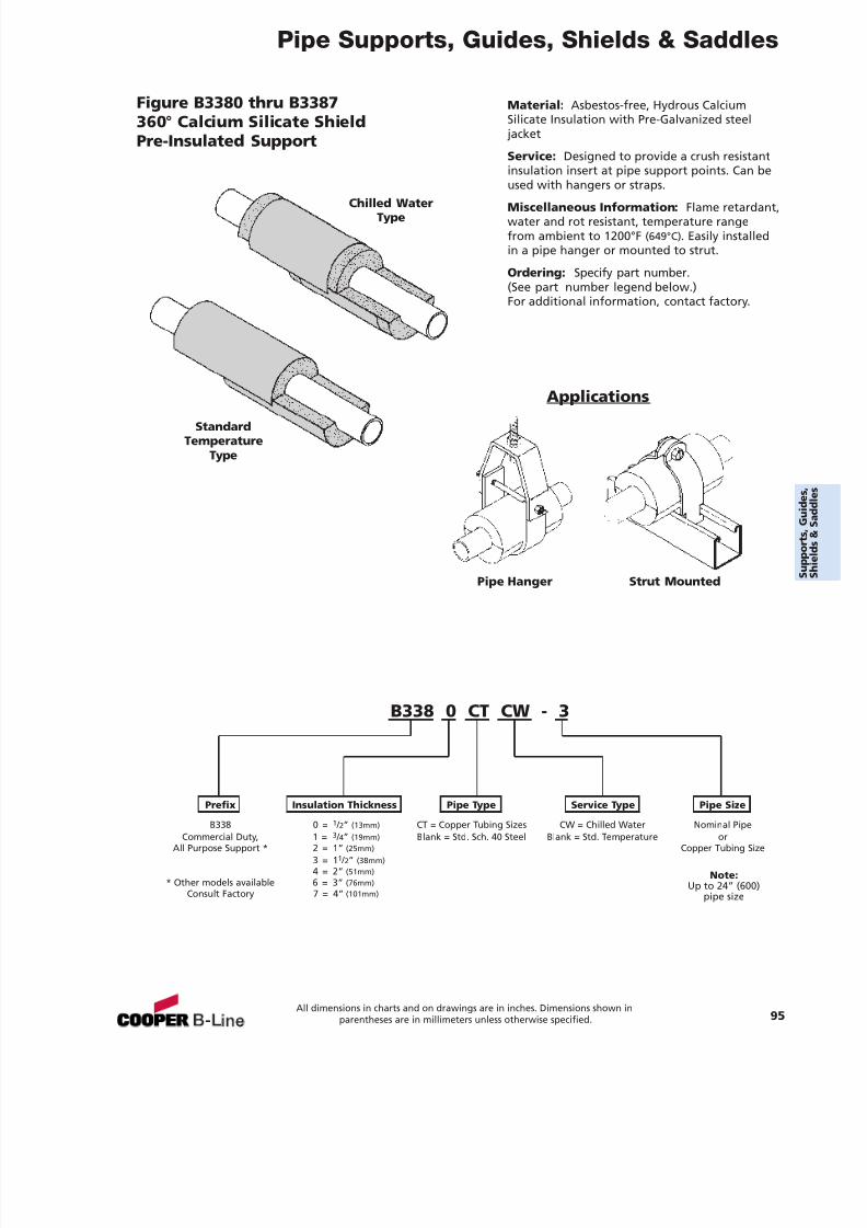
7/18/2019 PH Pipe Hanger Catalog
http://slidepdf.com/reader/full/ph-pipe-hanger-catalog 97/224
Pipe Supports, Guides, Shields & Saddles
All dimensions in charts and on drawings are in inches. Dimensions shown inparentheses are in millimeters unless otherwise specified. 95
Material: Asbestos-free, Hydrous CalciumSilicate Insulation with Pre-Galvanized steel
jacket
Service: Designed to provide a crush resistantinsulation insert at pipe support points. Can beused with hangers or straps.
Miscellaneous Information: Flame retardant,water and rot resistant, temperature rangefrom ambient to 1200°F (649°C). Easily installedin a pipe hanger or mounted to strut.
Ordering: Specify part number.(See part number legend below.)For additional information, contact factory.
Figure B3380 thru B3387360° Calcium Silicate ShieldPre-Insulated Support
Applications
Pipe Hanger
Chilled WaterType
StandardTemperature
Type
Strut Mounted
Prefix Insulation Thickness Pipe Type Service Type Pipe Size
B338 0 = 1 / 2” (13mm) CT = Copper Tubing Sizes CW = Chilled Water Nominal PipeCommercial Duty, 1 = 3 / 4” (19mm) Blank = Std. Sch. 40 Steel Blank = Std. Temperature or
All Purpose Support * 2 = 1” (25mm) Copper Tubing Size3 = 1 1 / 2” (38mm)4 = 2” (51mm)
* Other models available 6 = 3” (76mm)Consult Factory 7 = 4” (101mm)
B338 0 CT CW - 3
Note:Up to 24” (600)
pipe size
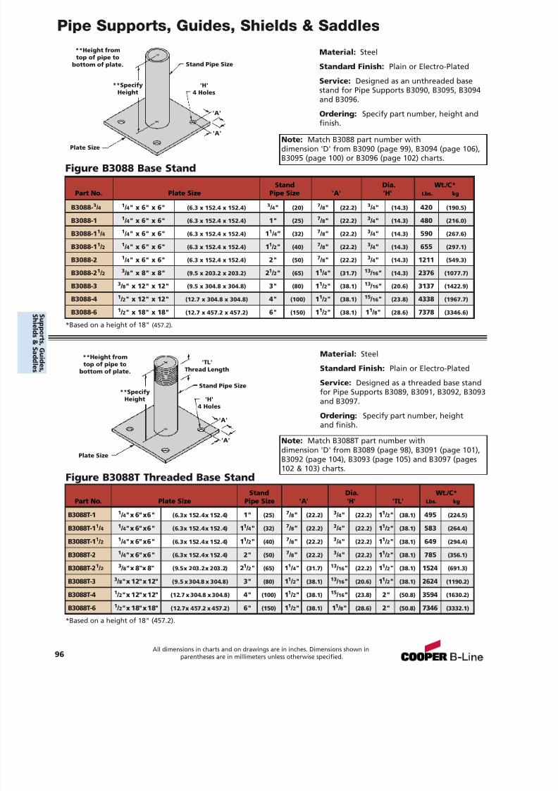
7/18/2019 PH Pipe Hanger Catalog
http://slidepdf.com/reader/full/ph-pipe-hanger-catalog 98/224
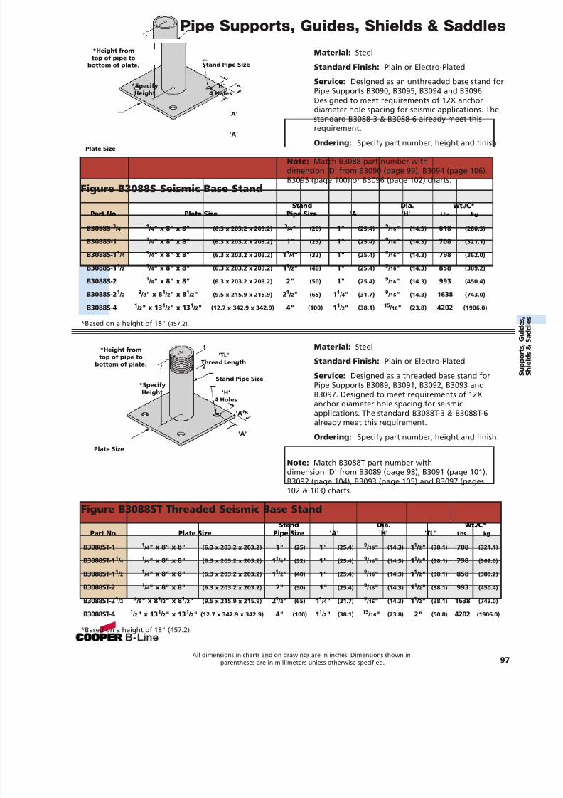
7/18/2019 PH Pipe Hanger Catalog
http://slidepdf.com/reader/full/ph-pipe-hanger-catalog 99/224
Pipe Supports, Guides, Shields & Saddles
Material: Steel
Standard Finish: Plain or Electro-Plated
Service: Designed as an unthreaded base stand forPipe Supports B3090, B3095, B3094 and B3096.Designed to meet requirements of 12X anchordiameter hole spacing for seismic applications. Thestandard B3088-3 & B3088-6 already meet this
requirement.Ordering: Specify part number, height and finish.
Figure B3088S Seismic Base Stand
Material: Steel
Standard Finish: Plain or Electro-Plated
Service: Designed as a threaded base stand forPipe Supports B3089, B3091, B3092, B3093 and
B3097. Designed to meet requirements of 12Xanchor diameter hole spacing for seismicapplications. The standard B3088T-3 & B3088T-6already meet this requirement.
Ordering: Specify part number, height and finish.
Figure B3088ST Threaded Seismic Base Stand
*Based on a height of 18" (457.2) .
*Based on a height of 18" (457.2).
'H'4 Holes
*SpecifyHeight
Plate Size
Stand Pipe Size
'A'
'A'
'H'4 Holes
Plate Size
Stand Pipe Size
'TL'Thread Length
'A'
'A'
Stand Dia. Wt./C*Part No. Plate Size Pipe Size 'A' 'H' 'TL' Lbs. kg
B3088ST-1 1 / 4" x 8" x 8" (6.3 x 203.2 x 203.2) 1" (25) 1" (25.4) 9 / 16 " (14.3) 11 / 2" (38.1) 708 (321.1)
B3088ST-1 1 / 4 1 / 4" x 8" x 8" (6.3 x 203.2 x 203.2) 11 / 4" (32) 1" (25.4) 9 / 16 " (14.3) 11 / 2" (38.1) 798 (362.0)
B3088ST-1 1 / 2 1 / 4" x 8" x 8" (6.3 x 203.2 x 203.2) 11 / 2" (40) 1" (25.4) 9 / 16 " (14.3) 11 / 2" (38.1) 858 (389.2)
B3088ST-2 1 / 4" x 8" x 8" (6.3 x 203.2 x 203.2) 2" (50) 1" (25.4) 9 / 16 " (14.3) 11 / 2" (38.1) 993 (450.4)
B3088ST-2 1 / 2 3 / 8" x 8 1 / 2" x 8 1 / 2" (9.5 x 215.9 x 215.9) 21 / 2" (65) 11 / 4" (31.7) 9 / 16 " (14.3) 11 / 2" (38.1) 1638 (743.0)
B3088ST-4 1 / 2" x 13 1 / 2" x 13 1 / 2" (12.7 x 342.9 x 342.9) 4" (100) 11 / 2" (38.1) 15 / 16 " (23.8) 2" (50.8) 4202 (1906.0)
Stand Dia. Wt./C*Part No. Plate Size Pipe Size 'A' 'H' Lbs. kg
B3088S- 3 / 4 1 / 4" x 8" x 8" (6.3 x 203.2 x 203.2) 3 / 4" (20) 1" (25.4) 9 / 16 " (14.3) 618 (280.3)
B3088S-1 1 / 4" x 8" x 8" (6.3 x 203.2 x 203.2) 1" (25) 1" (25.4) 9 / 16 " (14.3) 708 (321.1)
B3088S-1 1 / 4 1 / 4" x 8" x 8" (6.3 x 203.2 x 203.2) 11 / 4” (32) 1" (25.4) 9 / 16 " (14.3) 798 (362.0)
B3088S-1 1 / 2 1 / 4" x 8" x 8" (6.3 x 203.2 x 203.2) 11 / 2" (40) 1" (25.4) 9 / 16 " (14.3) 858 (389.2)
B3088S-2 1 / 4" x 8" x 8" (6.3 x 203.2 x 203.2) 2" (50) 1" (25.4) 9 / 16 " (14.3) 993 (450.4)
B3088S-2 1 / 2 3 / 8" x 8 1 / 2" x 8 1 / 2" (9.5 x 215.9 x 215.9) 21 / 2" (65) 11 / 4" (31.7) 9 / 16 " (14.3) 1638 (743.0)
B3088S-4 1 / 2" x 13 1 / 2" x 13 1 / 2" (12.7 x 342.9 x 342.9) 4" (100) 11 / 2" (38.1) 15 / 16 " (23.8) 4202 (1906.0)
All dimensions in charts and on drawings are in inches. Dimensions shown inparentheses are in millimeters unless otherwise specified. 97
*Height fromtop of pipe to
bottom of plate.
*SpecifyHeight
*Height fromtop of pipe to
bottom of plate.
Note: Match B3088T part number withdimension 'D' from B3089 (page 98), B3091 (page 101),B3092 (page 104), B3093 (page 105) and B3097 (pages102 & 103) charts.
Note: Match B3088 part number withdimension 'D' from B3090 (page 99), B3094 (page 106),B3095 (page 100) or B3096 (page 102) charts.
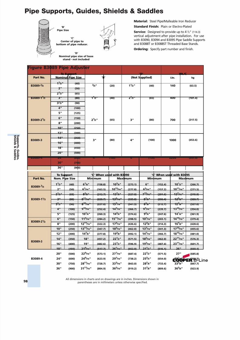
7/18/2019 PH Pipe Hanger Catalog
http://slidepdf.com/reader/full/ph-pipe-hanger-catalog 100/224
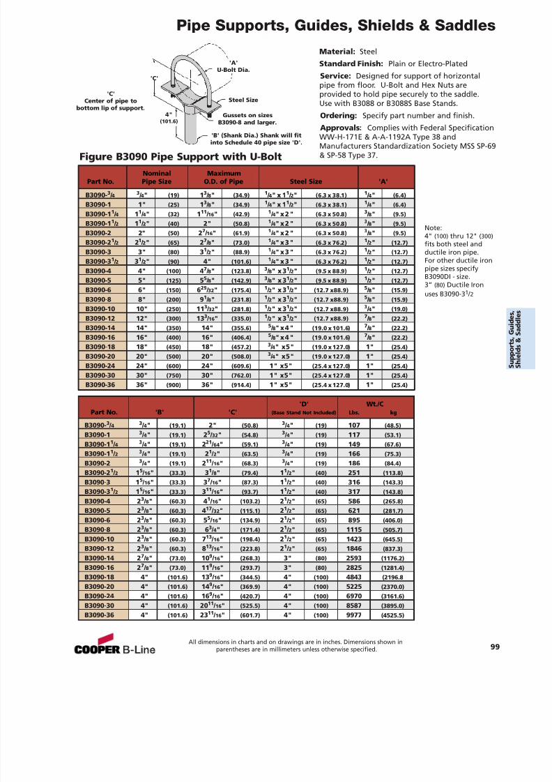
7/18/2019 PH Pipe Hanger Catalog
http://slidepdf.com/reader/full/ph-pipe-hanger-catalog 101/224
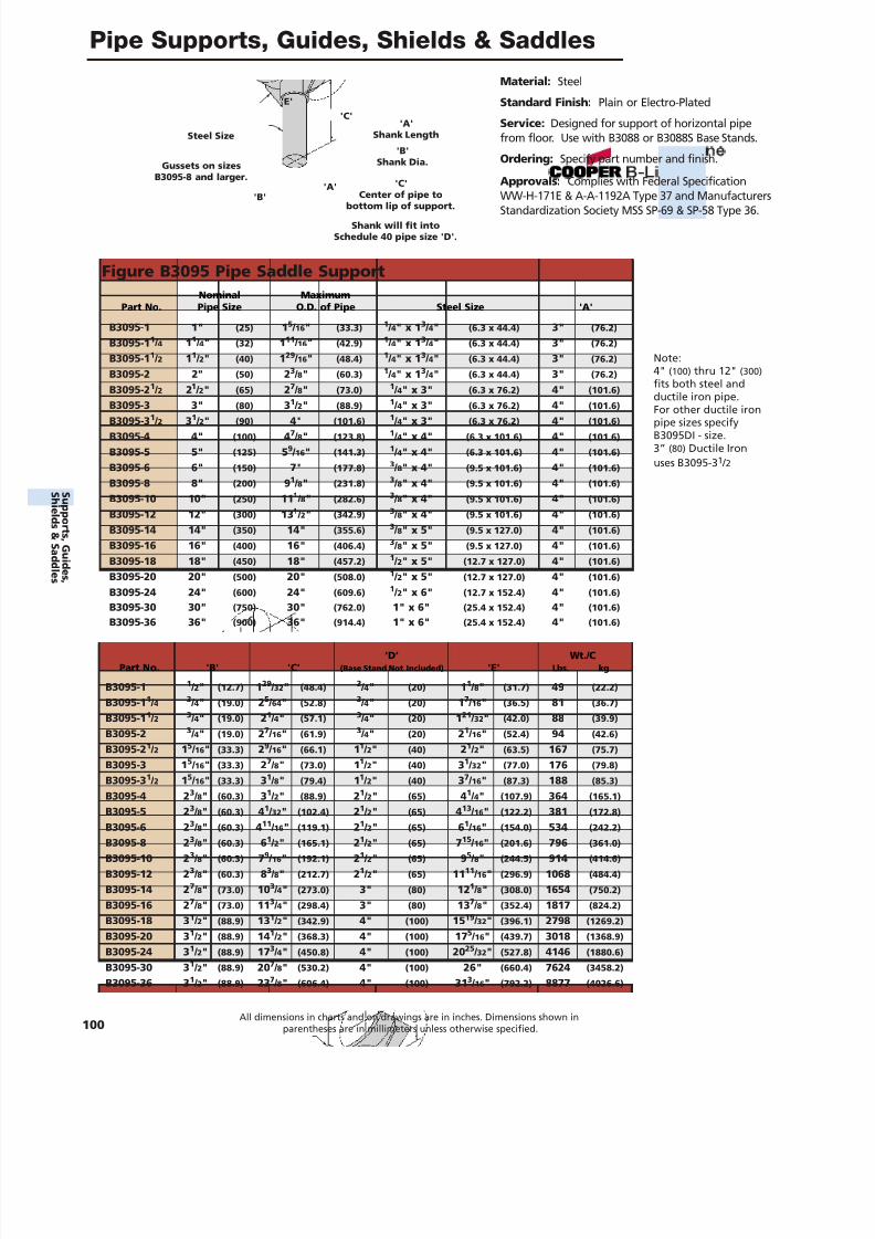
7/18/2019 PH Pipe Hanger Catalog
http://slidepdf.com/reader/full/ph-pipe-hanger-catalog 102/224
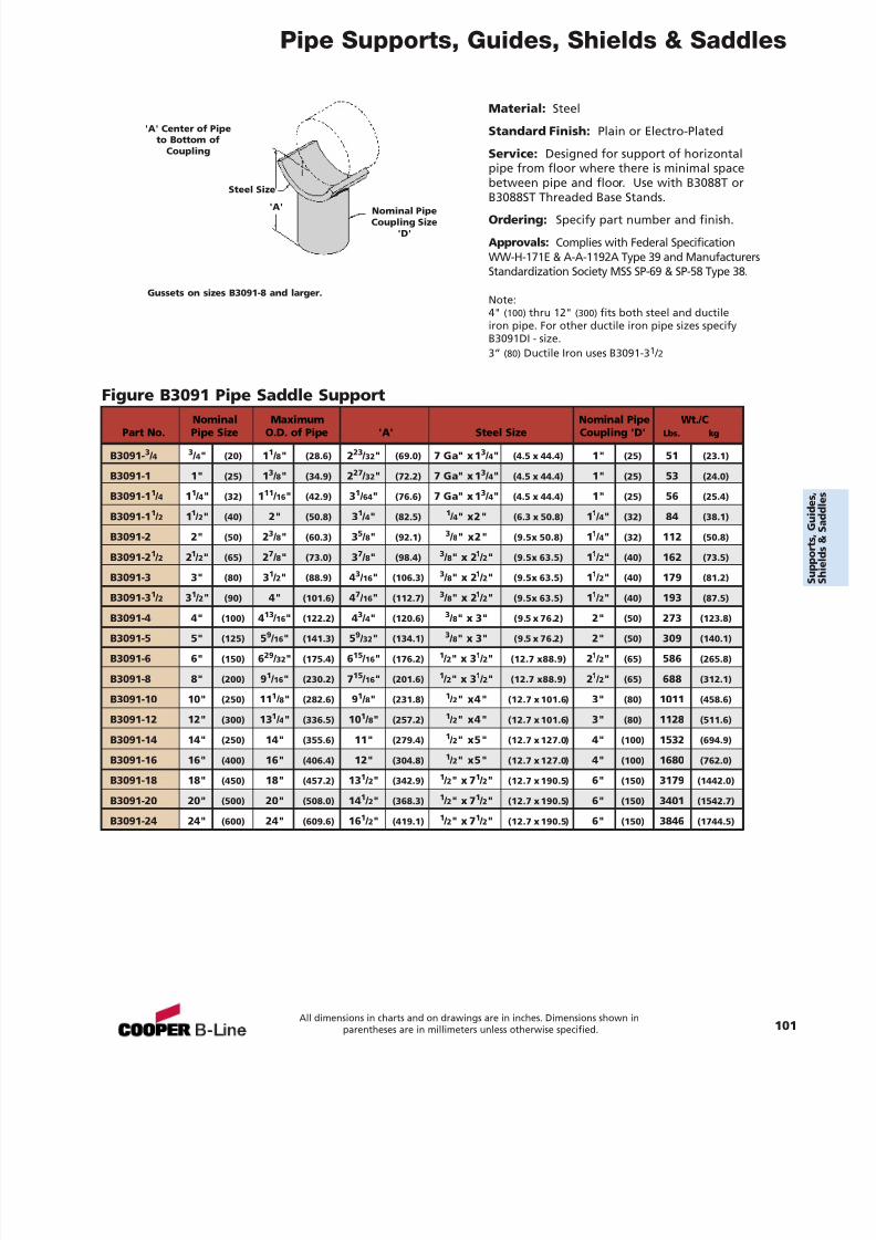
7/18/2019 PH Pipe Hanger Catalog
http://slidepdf.com/reader/full/ph-pipe-hanger-catalog 103/224
Pipe Supports, Guides, Shields & Saddles
Material: Steel
Standard Finish: Plain or Electro-Plated
Service: Designed for support of horizontalpipe from floor where there is minimal spacebetween pipe and floor. Use with B3088T orB3088ST Threaded Base Stands.
Ordering: Specify part number and finish.
Approvals: Complies with Federal SpecificationWW-H-171E & A-A-1192A Type 39 and ManufacturersStandardization Society MSS SP-69 & SP-58 Type 38.
Note:4" (100) thru 12" (300) fits both steel and ductileiron pipe. For other ductile iron pipe sizes specifyB3091DI - size.3” (80) Ductile Iron uses B3091-3 1 / 2
Figure B3091 Pipe Saddle Support
Nominal PipeCoupling Size
'D'
'A' Center of Pipeto Bottom of
Coupling
Gussets on sizes B3091-8 and larger.
Steel Size
Nominal Maximum Nominal Pipe Wt./CPart No. Pipe Size O.D. of Pipe 'A' Steel Size Coupling 'D' Lbs. kg
B3091- 3 / 4 3 / 4" (20) 11 / 8" (28.6) 223 / 32 " (69.0) 7 Ga" x 1 3 / 4" (4.5 x 44.4) 1" (25) 51 (23.1)
B3091-1 1" (25) 13 / 8" (34.9) 227 / 32 " (72.2) 7 Ga" x 1 3 / 4" (4.5 x 44.4) 1" (25) 53 (24.0)
B3091-1 1 / 4 11 / 4" (32) 111 / 16 " (42.9) 31 / 64 " (76.6) 7 Ga" x 1 3 / 4" (4.5 x 44.4) 1" (25) 56 (25.4)
B3091-1 1 / 2 11 / 2" (40) 2" (50.8) 31 / 4" (82.5) 1 / 4" x2" (6.3 x 50.8) 11 / 4" (32) 84 (38.1)
B3091-2 2" (50) 23 / 8" (60.3) 35 / 8" (92.1) 3 / 8" x2" (9.5x 50.8) 11 / 4" (32) 112 (50.8)
B3091-2 1 / 2 21 / 2" (65) 27 / 8" (73.0) 37 / 8" (98.4) 3 / 8" x 2 1 / 2" (9.5x 63.5) 11 / 2" (40) 162 (73.5)
B3091-3 3" (80) 31 / 2" (88.9) 43 / 16 " (106.3) 3 / 8" x 2 1 / 2" (9.5x 63.5) 11 / 2" (40) 179 (81.2)
B3091-3 1 / 2 31 / 2" (90) 4" (101.6) 47 / 16 " (112.7) 3 / 8" x 2 1 / 2" (9.5x 63.5) 11 / 2" (40) 193 (87.5)
B3091-4 4" (100) 413 / 16 " (122.2) 43 / 4" (120.6) 3 / 8" x 3" (9.5 x 76.2) 2" (50) 273 (123.8)
B3091-5 5" (125) 59 / 16 " (141.3) 59 / 32 " (134.1) 3 / 8" x 3" (9.5 x 76.2) 2" (50) 309 (140.1)
B3091-6 6" (150) 629 / 32 " (175.4) 615 / 16 " (176.2) 1 / 2" x 3 1 / 2" (12.7 x88.9) 21 / 2" (65) 586 (265.8)
B3091-8 8" (200) 91 / 16 " (230.2) 715 / 16 " (201.6) 1 / 2" x 3 1 / 2" (12.7 x88.9) 21 / 2" (65) 688 (312.1)
B3091-10 10" (250) 11 1 / 8" (282.6) 91 / 8" (231.8) 1 / 2" x4" (12.7 x 101.6) 3" (80) 1011 (458.6)
B3091-12 12" (300) 13 1 / 4" (336.5) 10 1 / 8" (257.2) 1 / 2" x4" (12.7 x 101.6) 3" (80) 1128 (511.6)
B3091-14 14" (250) 14" (355.6) 11" (279.4) 1 / 2" x5" (12.7 x 127.0) 4" (100) 1532 (694.9)
B3091-16 16" (400) 16" (406.4) 12" (304.8) 1 / 2" x5" (12.7 x 127.0) 4" (100) 1680 (762.0)
B3091-18 18" (450) 18" (457.2) 13 1 / 2" (342.9) 1 / 2" x 7 1 / 2" (12.7 x 190.5) 6" (150) 3179 (1442.0)
B3091-20 20" (500) 20" (508.0) 14 1 / 2" (368.3) 1 / 2" x 7 1 / 2" (12.7 x 190.5) 6" (150) 3401 (1542.7)
B3091-24 24" (600) 24" (609.6) 16 1 / 2" (419.1) 1 / 2" x 7 1 / 2" (12.7 x 190.5) 6" (150) 3846 (1744.5)
'A'
All dimensions in charts and on drawings are in inches. Dimensions shown inparentheses are in millimeters unless otherwise specified. 101
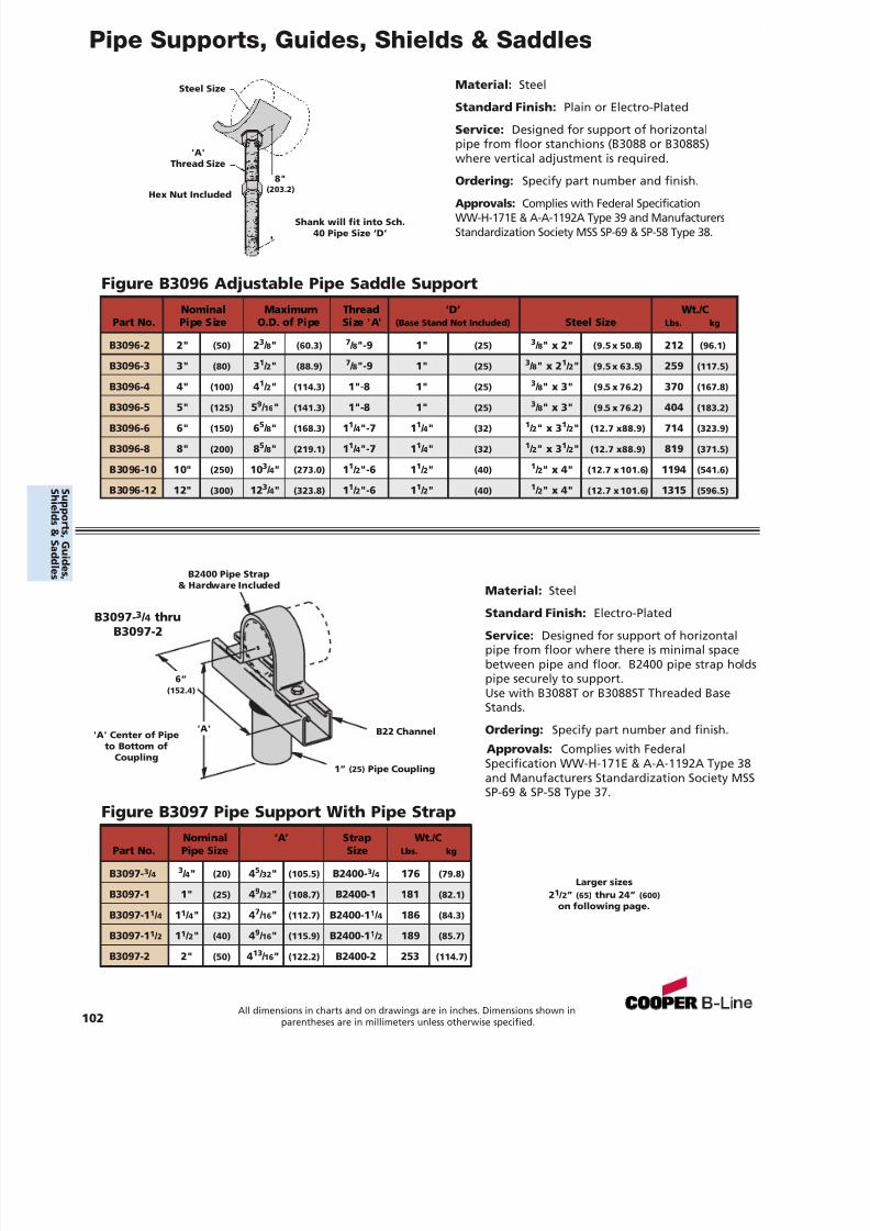
7/18/2019 PH Pipe Hanger Catalog
http://slidepdf.com/reader/full/ph-pipe-hanger-catalog 104/224
Pipe Supports, Guides, Shields & Saddles
102All dimensions in charts and on drawings are in inches. Dimensions shown in
parentheses are in millimeters unless otherwise specified.
Material: Steel
Standard Finish: Electro-Plated
Service: Designed for support of horizontalpipe from floor where there is minimal spacebetween pipe and floor. B2400 pipe strap holdspipe securely to support.Use with B3088T or B3088ST Threaded BaseStands.
Ordering: Specify part number and finish.
Approvals: Complies with FederalSpecification WW-H-171E & A-A-1192A Type 38and Manufacturers Standardization Society MSSSP-69 & SP-58 Type 37.
B2400 Pipe Strap& Hardware Included
'A' Center of Pipeto Bottom of
Coupling
Larger sizes21 / 2” (65) thru 24” (600)
on following page.
1” (25) Pipe Coupling
6”(152.4)
B22 Channel
B3097- 3 / 4 thruB3097-2
'A'
Figure B3097 Pipe Support With Pipe StrapNominal ‘A’ Strap Wt./C
Part No. Pipe Size Size Lbs. kg
B3097- 3 / 4 3 / 4" (20) 45 / 32 " (105.5) B2400- 3 / 4 176 (79.8)
B3097-1 1" (25) 49 / 32 " (108.7) B2400-1 181 (82.1)
B3097-1 1 / 4 11 / 4" (32) 47 / 16 " (112.7) B2400-1 1 / 4 186 (84.3)
B3097-1 1 / 2 11 / 2" (40) 49 / 16 " (115.9) B2400-1 1 / 2 189 (85.7)
B3097-2 2" (50) 413 / 16 " (122.2) B2400-2 253 (114.7)
Material: Steel
Standard Finish: Plain or Electro-Plated
Service: Designed for support of horizontalpipe from floor stanchions (B3088 or B3088S)where vertical adjustment is required.
Ordering: Specify part number and finish.
Approvals: Complies with Federal SpecificationWW-H-171E & A-A-1192A Type 39 and ManufacturersStandardization Society MSS SP-69 & SP-58 Type 38.
Figure B3096 Adjustable Pipe Saddle Support
Steel Size
'A'Thread Size
8"(203.2)Hex Nut Included
Shank will fit into Sch.40 Pipe Size ‘D’
Nominal Maximum Thread ‘D’ Wt./CPart No. Pipe Size O.D. of Pipe Size 'A' (Base Stand Not Included) Steel Size Lbs. kg
B3096-2 2" (50) 23 / 8" (60.3) 7 / 8"-9 1" (25) 3 / 8" x 2" (9.5 x 50.8) 212 (96.1)
B3096-3 3" (80) 31 / 2" (88.9) 7 / 8"-9 1" (25) 3 / 8" x 2 1 / 2" (9.5 x 63.5) 259 (117.5)
B3096-4 4" (100) 41 / 2" (114.3) 1"-8 1" (25) 3 / 8" x 3" (9.5 x 76.2) 370 (167.8)
B3096-5 5" (125) 59 / 16 " (141.3) 1"-8 1" (25) 3 / 8" x 3" (9.5 x 76.2) 404 (183.2)
B3096-6 6" (150) 65 / 8" (168.3) 11 / 4"-7 1 1 / 4" (32) 1 / 2" x 3 1 / 2" (12.7 x88.9) 714 (323.9)
B3096-8 8" (200) 85 / 8" (219.1) 11 / 4"-7 1 1 / 4" (32) 1 / 2" x 3 1 / 2" (12.7 x88.9) 819 (371.5)
B3096-10 10" (250) 10 3 / 4" (273.0) 11 / 2"-6 1 1 / 2" (40) 1 / 2" x 4" (12.7 x 101.6) 1194 (541.6)
B3096-12 12" (300) 12 3 / 4" (323.8) 11 / 2"-6 1 1 / 2" (40) 1 / 2" x 4" (12.7 x 101.6) 1315 (596.5)S uppor t s ,Gui d es ,
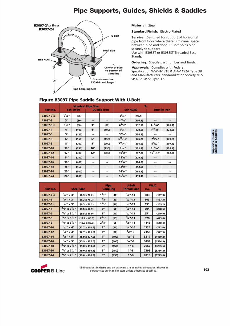
7/18/2019 PH Pipe Hanger Catalog
http://slidepdf.com/reader/full/ph-pipe-hanger-catalog 105/224
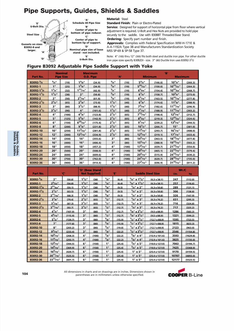
7/18/2019 PH Pipe Hanger Catalog
http://slidepdf.com/reader/full/ph-pipe-hanger-catalog 106/224
Pipe Supports, Guides, Shields & SaddlesMaterial: SteelStandard Finish: Plain or Electro-PlatedService: Designed for support of horizontal pipe from floor where verticaladjustment is required. U-Bolt and Hex Nuts are provided to hold pipesecurely to the saddle. Use with B3088T Threaded Base Stand.Ordering: Specify part number and finish.Approvals: Complies with Federal Specification WW-H-171E &A-A-1192A Type 38 and Manufacturers Standardization SocietyMSS SP-69 & SP-58 Type 37.
'E'U-Bolt Dia.
Steel Size
Gussets on sizesB3092-8 and
larger.
'A'Schedule 40 Pipe Size
'B'Center of pipe to
bottom of pipe reducer.'C'
Center of pipe tobottom lip of support.
'D'Nominal pipe size of base
stand - not included.'E'
U-Bolt Dia.
'A'
'D'
'C'
'B'
Note: 4" (100) thru 12" (300) fits both steel and ductile iron pipe. For other ductileiron pipe sizes specify B3092DI - size. 3” (80) Ductile Iron uses B3092-3 1 / 2
Nominal Maximum 'B'Part No. Pipe Size O.D. Pipe 'A' Minimum Maximum
B3092- 3 / 4 3 / 4" (19) 13 / 8" (34.9) 3 / 4" (19) 53 / 4" (146.0) 10 1 / 4" (260.3)
B3092-1 1" (25) 13 / 8" (34.9) 3 / 4" (19) 529 / 32 " (150.0) 10 13 / 32 " (264.3)
B3092-1 1 / 4 11 / 4" (32) 111 / 16 " (42.9) 3 / 4" (19) 65 / 64 " (154.4) 10 37 / 64 " (268.7)
B3092-1 1 / 2 11 / 2" (38) 2" (50.8) 3 / 4" (19) 61 / 4" (158.7) 10 3 / 4" (273.0)
B3092-2 2" (50) 27 / 16 " (61.9) 3 / 4" (19) 67 / 16 " (163.5) 10 15 / 16 " (277.8)
B3092-2 1 / 2 21 / 2" (65) 27 / 8" (73.0) 11 / 2" (40) 67 / 8" (174.6) 11 3 / 8" (288.9)
B3092-3 3" (80) 31 / 2" (88.9) 11 / 2" (40) 73 / 16 " (182.6) 11 11 / 16 " (296.9)
B3092-3 1 / 2 31 / 2" (90) 4" (101.6) 11 / 2" (40) 77 / 16 " (188.9) 11 15 / 16 " (303.2)
B3092-4 4" (100) 47 / 8" (123.8) 21 / 2" (65) 713 / 16 " (198.4) 12 5 / 16 " (312.7)
B3092-5 5" (125) 55 / 8" (142.9) 21 / 2" (65) 89 / 32 " (210.3) 12 25 / 32 " (324.6)
B3092-6 6" (150) 629 / 32 " (175.4) 21 / 2" (65) 91 / 16 " (230.2) 13 9 / 16 " (344.5)
B3092-8 8" (200) 91 / 8" (231.8) 21 / 2" (65) 10 1 / 2" (266.7) 15" (381.0)
B3092-10 10" (250) 11 3 / 32 " (281.8) 21 / 2" (65) 11 9 / 16 " (293.7) 16 1 / 16 " (408.0)
B3092-12 12" (300) 13 3 / 16 " (334.9) 21 / 2" (65) 12 9 / 16 " (319.1) 17 1 / 16 " (433.4)
B3092-14 14" (350) 14" (355.6) 3" (80) 14 5 / 16 " (363.5) 18 13 / 16 " (477.8)
B3092-16 16" (400) 16" (406.4) 3" (80) 15 5 / 16 " (388.9) 19 13 / 16 " (503.2)
B3092-18 18" (450) 18" (457.2) 4" (100) 17 5 / 16 " (439.7) 21 13 / 16 " (554.0)
B3092-20 20" (500) 20" (508.0) 4" (100) 18 5 / 16 " (465.1) 22 13 / 16 " (579.4)
B3092-24 24" (600) 24" (609.6) 4" (100) 20 5 / 16 " (515.9) 24 13 / 16 " (630.2)
B3092-30 30" (750) 30" (762.0) 4" (100) 24 7 / 16 " (620.7) 28 15 / 16 " (735.0)
B3092-36 36"(900)
36"(914.4)
4"(100)
277
/ 16
"(696.9)
3115
/ 16
"(811.2)
'D' (Base Stand Wt./CPart No. 'C' Not Supplied) 'E' Saddle Steel Size Lbs. kg
B3092- 3 / 4 2" (50.8) 11 / 2" (38) 1 / 4" (6.4) 1 / 4" x 1 1 / 2" (6.3 x 38.1) 247 (112.0)
B3092-1 2 5 / 32 " (54.8) 11 / 2" (38) 1 / 4" (6.4) 1 / 4" x 1 1 / 2" (6.3 x 38.1) 257 (116.6)
B3092-1 1 / 4 221 / 64 " (59.1) 11 / 2" (38) 3 / 8" (9.5) 1 / 4" x 2" (6.3 x 50.8) 289 (131.1)
B3092-1 1 / 2 21 / 2" (63.5) 11 / 2" (38) 3 / 8" (9.5) 1 / 4" x 2" (6.3 x 50.8) 306 (138.8)
B3092-2 2 11 / 16 " (68.3) 11 / 2" (38) 3 / 8" (9.5) 1 / 4" x 2" (6.3 x 50.8) 326 (147.9)
B3092-2 1 / 2 31 / 8" (79.4) 21 / 2" (65) 1 / 2" (12.7) 1 / 4" x 3" (6.3 x 76.2) 651 (295.3)
B3092-3 3 7 / 16 " (87.3) 21 / 2" (65) 1 / 2" (12.7) 1 / 4" x 3" (6.3 x 76.2) 716 (324.8)
B3092-3 1 / 2 311 / 16 " (93.7) 21 / 2" (65) 1 / 2" (12.7) 1 / 4" x 3" (6.3 x 76.2) 717 (325.2)
B3092-4 4 1 / 4" (107.9) 3" (80) 1 / 2" (12.7) 3 / 8" x 3 1 / 2" (9.5 x 88.9) 1286 (583.3)
B3092-5 4 9 / 16 " (115.9) 3" (80) 1 / 2" (12.7) 3 / 8" x 3 1 / 2" (9.5 x 88.9) 1321 (599.2)
B3092-6 5 1 / 2" (139.7) 3" (80) 5 / 8" (15.9) 1 / 2" x 3 1 / 2" (12.7 x 88.9) 1595 (723.5)B3092-8 7" (177.8) 3" (80) 5 / 8" (15.9) 1 / 2" x 3 1 / 2" (12.7 x 88.9) 1815 (823.3)
B3092-10 8" (203.2) 3" (80) 3 / 4" (19.0) 1 / 2" x 3 1 / 2" (12.7 x 88.9) 2123 (963.0)
B3092-12 9 3 / 16 " (233.4) 3" (80) 7 / 8" (22.2) 1 / 2" x 3 1 / 2" (12.7 x 88.9) 2546 (1154.8)
B3092-14 10 9 / 16 " (268.3) 4" (100) 7 / 8" (22.2) 5 / 8" x 4" (15.9 x 101.6) 3593 (1629.8)
B3092-16 11 9 / 16 " (293.7) 4" (100) 7 / 8" (22.2) 5 / 8" x 4" (15.9 x 101.6) 3825 (1735.0)
B3092-18 13 9 / 16 " (344.5) 6" (150) 1" (25.4) 3 / 4" x 5" (19.0 x 127.0) 7043 (3194.7)
B3092-20 14 9 / 16 " (369.9) 6" (150) 1" (25.4) 3 / 4" x 5" (19.0 x 127.0) 7425 (3368.0)
B3092-24 16 9 / 16 " (420.7) 6" (150) 1" (25.4) 1" x 5" (25.4 x 127.0) 9170 (4159.5)
B3092-30 20 11 / 16 " (525.5) 6" (150) 1" (25.4) 1" x 5" (25.4 x 127.0) 10787 (4893.0)
B3092-36 23 11 / 16 " (601.7) 6" (150) 1" (25.4) 1" x 5" (25.4 x 127.0) 12177 (5523.5)
Figure B3092 Adjustable Pipe Saddle Support with Yoke
104All dimensions in charts and on drawings are in inches. Dimensions shown in
parentheses are in millimeters unless otherwise specified.
S uppor t s ,Gui d es ,
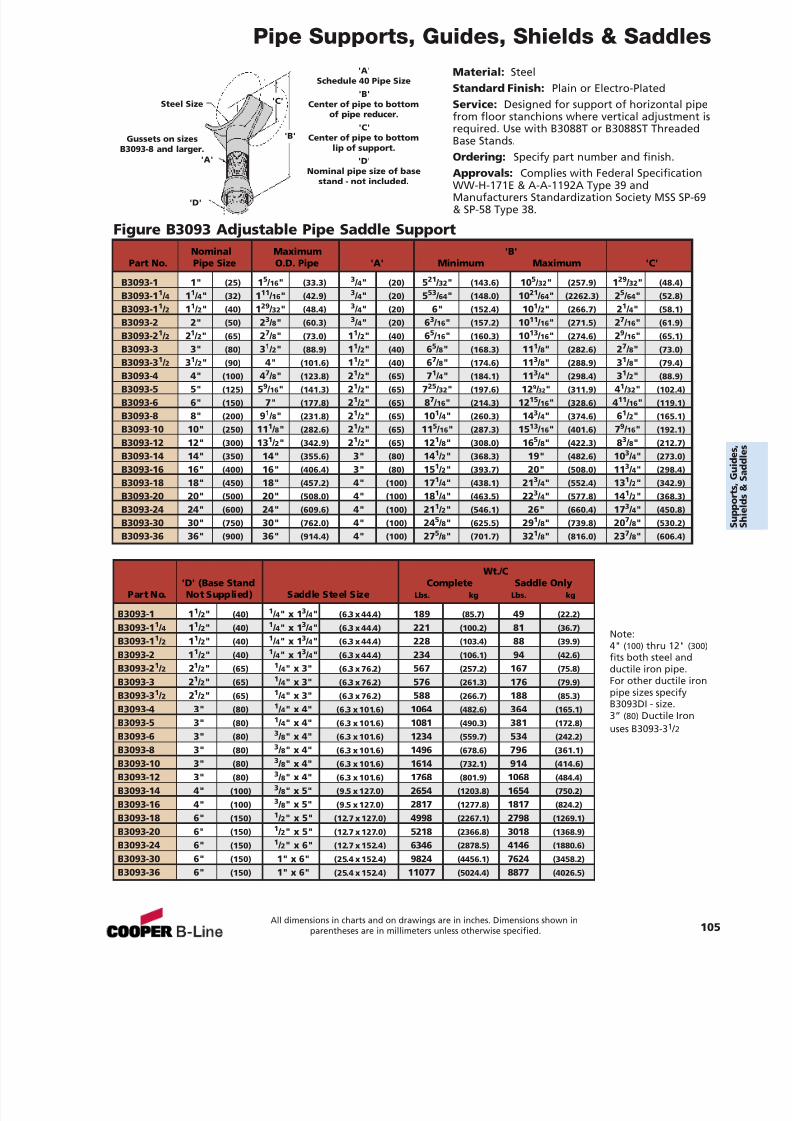
7/18/2019 PH Pipe Hanger Catalog
http://slidepdf.com/reader/full/ph-pipe-hanger-catalog 107/224
Pipe Supports, Guides, Shields & Saddles
Material: SteelStandard Finish: Plain or Electro-PlatedService: Designed for support of horizontal pipefrom floor stanchions where vertical adjustment isrequired. Use with B3088T or B3088ST ThreadedBase Stands.Ordering: Specify part number and finish.Approvals: Complies with Federal SpecificationWW-H-171E & A-A-1192A Type 39 andManufacturers Standardization Society MSS SP-69& SP-58 Type 38.
Figure B3093 Adjustable Pipe Saddle Support
Steel Size
Gussets on sizesB3093-8 and larger.
'A'Schedule 40 Pipe Size
'B'Center of pipe to bottom
of pipe reducer.'C'
Center of pipe to bottomlip of support.
'D'Nominal pipe size of base
stand - not included.
'A'
'D'
'C'
'B'
Note:4" (100) thru 12" (300)fits both steel andductile iron pipe.For other ductile ironpipe sizes specifyB3093DI - size.3” (80) Ductile Ironuses B3093-3 1 / 2
Nominal Maximum 'B'Part No. Pipe Size O.D. Pipe 'A' Minimum Maximum 'C'
B3093-1 1" (25) 15 / 16 " (33.3) 3 / 4" (20) 521 / 32 " (143.6) 10 5 / 32 " (257.9) 129 / 32 " (48.4)
B3093-1 1 / 4 11 / 4" (32) 111 / 16 " (42.9) 3 / 4" (20) 553 / 64 " (148.0) 10 21 / 64 " (2262.3) 25 / 64 " (52.8)
B3093-1 1 / 2 11 / 2" (40) 129 / 32 " (48.4) 3 / 4" (20) 6" (152.4) 10 1 / 2" (266.7) 21 / 4" (58.1)
B3093-2 2" (50) 23 / 8" (60.3) 3 / 4" (20) 63 / 16 " (157.2) 10 11 / 16 " (271.5) 27 / 16 " (61.9)
B3093-2 1 / 2 21 / 2" (65) 27 / 8" (73.0) 11 / 2" (40) 65 / 16 " (160.3) 10 13 / 16 " (274.6) 29 / 16 " (65.1)
B3093-3 3" (80) 31 / 2" (88.9) 11 / 2" (40) 65 / 8" (168.3) 11 1 / 8" (282.6) 27 / 8" (73.0)
B3093-3 1 / 2 31 / 2" (90) 4" (101.6) 11 / 2" (40) 67 / 8" (174.6) 11 3 / 8" (288.9) 31 / 8" (79.4)
B3093-4 4" (100) 47 / 8" (123.8) 21 / 2" (65) 71 / 4" (184.1) 11 3 / 4" (298.4) 31 / 2" (88.9)
B3093-5 5" (125) 59 / 16 " (141.3) 21 / 2" (65) 725 / 32 " (197.6) 12 9 / 32 " (311.9) 41 / 32 " (102.4)
B3093-6 6" (150) 7" (177.8) 21 / 2" (65) 87 / 16 " (214.3) 12 15 / 16 " (328.6) 411 / 16 " (119.1)
B3093-8 8" (200) 91 / 8" (231.8) 21 / 2" (65) 10 1 / 4" (260.3) 14 3 / 4" (374.6) 61 / 2" (165.1)
B3093-10 10" (250) 11 1 / 8" (282.6) 21 / 2" (65) 11 5 / 16 " (287.3) 15 13 / 16 " (401.6) 79 / 16 " (192.1)
B3093-12 12" (300) 13 1 / 2" (342.9) 21 / 2" (65) 12 1 / 8" (308.0) 16 5 / 8" (422.3) 83 / 8" (212.7)
B3093-14 14" (350) 14" (355.6) 3" (80) 14 1 / 2" (368.3) 19" (482.6) 10 3 / 4" (273.0)
B3093-16 16" (400) 16" (406.4) 3" (80) 15 1 / 2" (393.7) 20" (508.0) 11 3 / 4" (298.4)
B3093-18 18" (450) 18" (457.2) 4" (100) 17 1 / 4" (438.1) 21 3 / 4" (552.4) 13 1 / 2" (342.9)
B3093-20 20" (500) 20" (508.0) 4" (100) 18 1 / 4" (463.5) 22 3 / 4" (577.8) 14 1 / 2" (368.3)
B3093-24 24" (600) 24" (609.6) 4" (100) 21 1 / 2" (546.1) 26" (660.4) 17 3 / 4" (450.8)
B3093-30 30" (750) 30" (762.0) 4" (100) 24 5 / 8" (625.5) 29 1 / 8" (739.8) 20 7 / 8" (530.2)
B3093-36 36" (900) 36" (914.4) 4" (100) 27 5 / 8" (701.7) 32 1 / 8" (816.0) 23 7 / 8" (606.4)
Wt./C'D' (Base Stand Complete Saddle Only
Part No. Not Supplied) Saddle Steel Size Lbs. kg Lbs. kg
B3093-1 1 1 / 2" (40) 1 / 4" x 1 3 / 4" (6.3 x 44.4) 189 (85.7) 49 (22.2)
B3093-1 1 / 4 11 / 2" (40) 1 / 4" x 1 3 / 4" (6.3 x 44.4) 221 (100.2) 81 (36.7)
B3093-1 1 / 2 11 / 2" (40) 1 / 4" x 1 3 / 4" (6.3 x 44.4) 228 (103.4) 88 (39.9)
B3093-2 1 1 / 2" (40) 1 / 4" x 1 3 / 4" (6.3 x 44.4) 234 (106.1) 94 (42.6)
B3093-2 1 / 2 21 / 2" (65) 1 / 4" x 3" (6.3 x 76.2) 567 (257.2) 167 (75.8)
B3093-3 2 1 / 2" (65) 1 / 4" x 3" (6.3 x 76.2) 576 (261.3) 176 (79.9)
B3093-3 1 / 2 21 / 2" (65) 1 / 4" x 3" (6.3 x 76.2) 588 (266.7) 188 (85.3)
B3093-4 3" (80) 1 / 4" x 4" (6.3 x 101.6) 1064 (482.6) 364 (165.1)
B3093-5 3" (80) 1 / 4" x 4" (6.3 x 101.6) 1081 (490.3) 381 (172.8)
B3093-6 3" (80) 3 / 8" x 4" (6.3 x 101.6) 1234 (559.7) 534 (242.2)
B3093-8 3" (80) 3 / 8" x 4" (6.3 x 101.6) 1496 (678.6) 796 (361.1)
B3093-10 3" (80) 3 / 8" x 4" (6.3 x 101.6) 1614 (732.1) 914 (414.6)
B3093-12 3" (80) 3 / 8" x 4" (6.3 x 101.6) 1768 (801.9) 1068 (484.4)
B3093-14 4" (100) 3 / 8" x 5" (9.5 x 127.0) 2654 (1203.8) 1654 (750.2)
B3093-16 4" (100) 3 / 8" x 5" (9.5 x 127.0) 2817 (1277.8) 1817 (824.2)
B3093-18 6" (150) 1 / 2" x 5" (12.7 x 127.0) 4998 (2267.1) 2798 (1269.1)
B3093-20 6" (150) 1 / 2" x 5" (12.7 x 127.0) 5218 (2366.8) 3018 (1368.9)
B3093-24 6" (150) 1 / 2" x 6" (12.7 x 152.4) 6346 (2878.5) 4146 (1880.6)
B3093-30 6" (150) 1" x 6" (25.4 x 152.4) 9824 (4456.1) 7624 (3458.2)
B3093-36 6" (150) 1" x 6" (25.4 x 152.4) 11077 (5024.4) 8877 (4026.5)
All dimensions in charts and on drawings are in inches. Dimensions shown inparentheses are in millimeters unless otherwise specified. 105
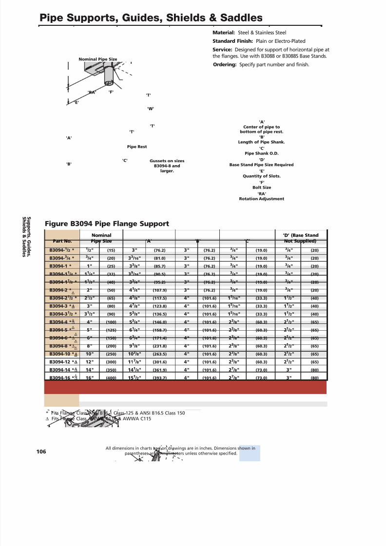
7/18/2019 PH Pipe Hanger Catalog
http://slidepdf.com/reader/full/ph-pipe-hanger-catalog 108/224
Pipe Supports, Guides, Shields & Saddles
106All dimensions in charts and on drawings are in inches. Dimensions shown in
parentheses are in millimeters unless otherwise specified.
Material: Steel & Stainless Steel
Standard Finish: Plain or Electro-Plated
Service: Designed for support of horizontal pipe atthe flanges. Use with B3088 or B3088S Base Stands.
Ordering: Specify part number and finish.Nominal Pipe Size
Gussets on sizesB3094-8 and
larger.
'A'Center of pipe to
bottom of pipe rest.'B'
Length of Pipe Shank.'C'
Pipe Shank O.D.'D'
Base Stand Pipe Size Required'E'
Quantity of Slots.'F'
Bolt Size'RA'
Rotation Adjustment
'B'
'A'
'E'
'F''T'
'T''T'
Pipe Rest
'C'
'W'
'RA'
Nominal ‘D’ (Base StandPart No. Pipe Size 'A' 'B' ‘C’ Not Supplied)
B3094- 1 / 2 * 1 / 2" (15) 3" (76.2) 3" (76.2) 3 / 4" (19.0) 3 / 4" (20)
B3094- 3 / 4 * 3 / 4" (20) 33 / 16 " (81.0) 3" (76.2) 3 / 4" (19.0) 3 / 4" (20)
B3094-1 * 1" (25) 33 / 8" (85.7) 3" (76.2) 3 / 4" (19.0) 3 / 4" (20)
B3094-1 1 / 4 * 1 1 / 4" (32) 39 / 16 " (90.5) 3" (76.2) 3 / 4" (19.0) 3 / 4" (20)
B3094-1 1 / 2 * 1 1 / 2" (40) 33 / 4" (95.2) 3" (76.2) 3 / 4" (19.0) 3 / 4" (20)
B3094-2 * 2" (50) 41 / 4" (107.9) 3" (76.2) 3 / 4" (19.0) 3 / 4" (20)
B3094-2 1 / 2 * 2 1 / 2" (65) 45 / 8" (117.5) 4" (101.6) 15 / 16 " (33.3) 11 / 2" (40)
B3094-3 * ∆ 3" (80) 47 / 8" (123.8) 4" (101.6) 15 / 16 " (33.3) 11 / 2" (40)
B3094-3 1 / 2 * 3 1 / 2" (90) 53 / 8" (136.5) 4" (101.6) 15 / 16 " (33.3) 11 / 2" (40)
B3094-4 * ∆ 4" (100) 53 / 4" (146.0) 4" (101.6) 23 / 8" (60.3) 21 / 2" (65)
B3094-5 * 5" (125) 61 / 4" (158.7) 4" (101.6) 23 / 8" (60.3) 21 / 2" (65)
B3094-6 * ∆ 6" (150) 63 / 4" (171.4) 4" (101.6) 23 / 8" (60.3) 21 / 2" (65)
B3094-8 * ∆ 8" (200) 91 / 8" (231.8) 4" (101.6) 23 / 8" (60.3) 21 / 2" (65)
B3094-10 * ∆ 10" (250) 10 3 / 8" (263.5) 4" (101.6) 23 / 8" (60.3) 21 / 2" (65)
B3094-12 * ∆ 12" (300) 11 7 / 8" (301.6) 4" (101.6) 23 / 8" (60.3) 21 / 2" (65)
B3094-14 * ∆ 14" (350) 14 1 / 4" (361.9) 4" (101.6) 27 / 8" (73.0) 3" (80)
B3094-16 * ∆ 16" (400) 15 1 / 2" (393.7) 4" (101.6) 27 / 8" (73.0) 3" (80)
B3094-18 * ∆ 18" (450) 17" (431.8) 4" (101.6) 31 / 2" (88.9) 4" (100)
B3094-20 * ∆ 20" (500) 18 1 / 4" (463.5) 4" (101.6) 31 / 2" (88.9) 4" (100)
B3094-24 * ∆ 24" (600) 21 3 / 4" (552.4) 4" (101.6) 31 / 2" (88.9) 4" (100)
Figure B3094 Pipe Flange Support
* Fits Flange Class ANSI B16.1 Class 125 & ANSI B16.5 Class 150∆ Fits Flange Class AWWA C110 & AWWA C115
S uppor t s ,Gui d es ,
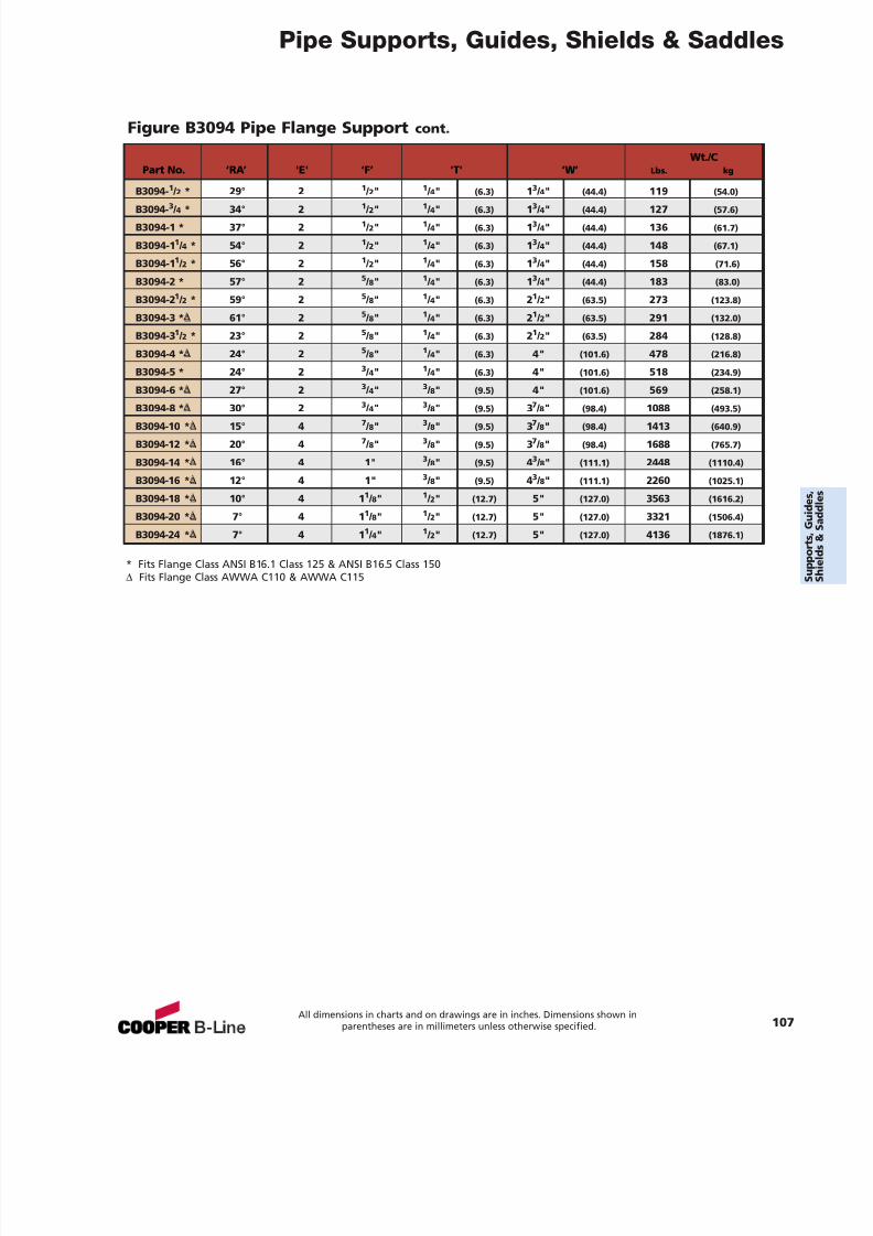
7/18/2019 PH Pipe Hanger Catalog
http://slidepdf.com/reader/full/ph-pipe-hanger-catalog 109/224
Pipe Supports, Guides, Shields & Saddles
All dimensions in charts and on drawings are in inches. Dimensions shown inparentheses are in millimeters unless otherwise specified. 107
Wt./CPart No. ‘RA’ 'E' ‘F’ 'T' ‘W’ Lbs. kg
B3094- 1 / 2 * 29° 2 1 / 2" 1 / 4" (6.3) 13 / 4" (44.4) 119 (54.0)
B3094- 3 / 4 * 34° 2 1 / 2" 1 / 4" (6.3) 13 / 4" (44.4) 127 (57.6)
B3094-1 * 37° 2 1 / 2" 1 / 4" (6.3) 13 / 4" (44.4) 136 (61.7)
B3094-1 1 / 4 * 54° 2 1 / 2" 1 / 4" (6.3) 13 / 4" (44.4) 148 (67.1)
B3094-1 1 / 2 * 56° 2 1 / 2" 1 / 4" (6.3) 13 / 4" (44.4) 158 (71.6)
B3094-2 * 57° 2 5 / 8" 1 / 4" (6.3) 13 / 4" (44.4) 183 (83.0)
B3094-2 1 / 2 * 59° 2 5 / 8" 1 / 4" (6.3) 21 / 2" (63.5) 273 (123.8)
B3094-3 * ∆ 61° 2 5 / 8" 1 / 4" (6.3) 21 / 2" (63.5) 291 (132.0)
B3094-3 1 / 2 * 23° 2 5 / 8" 1 / 4" (6.3) 21 / 2" (63.5) 284 (128.8)
B3094-4 * ∆ 24° 2 5 / 8" 1 / 4" (6.3) 4" (101.6) 478 (216.8)
B3094-5 * 24° 2 3 / 4" 1 / 4" (6.3) 4" (101.6) 518 (234.9)
B3094-6 * ∆ 27° 2 3 / 4" 3 / 8" (9.5) 4" (101.6) 569 (258.1)
B3094-8 * ∆ 30° 2 3 / 4" 3 / 8" (9.5) 37 / 8" (98.4) 1088 (493.5)B3094-10 * ∆ 15° 4 7 / 8" 3 / 8" (9.5) 37 / 8" (98.4) 1413 (640.9)
B3094-12 * ∆ 20° 4 7 / 8" 3 / 8" (9.5) 37 / 8" (98.4) 1688 (765.7)
B3094-14 * ∆ 16° 4 1" 3 / 8" (9.5) 43 / 8" (111.1) 2448 (1110.4)
B3094-16 * ∆ 12° 4 1" 3 / 8" (9.5) 43 / 8" (111.1) 2260 (1025.1)
B3094-18 * ∆ 10° 4 1 1 / 8" 1 / 2" (12.7) 5" (127.0) 3563 (1616.2)
B3094-20 * ∆ 7° 4 1 1 / 8" 1 / 2" (12.7) 5" (127.0) 3321 (1506.4)
B3094-24 * ∆ 7° 4 1 1 / 4" 1 / 2" (12.7) 5" (127.0) 4136 (1876.1)
Figure B3094 Pipe Flange Support cont.
* Fits Flange Class ANSI B16.1 Class 125 & ANSI B16.5 Class 150∆ Fits Flange Class AWWA C110 & AWWA C115
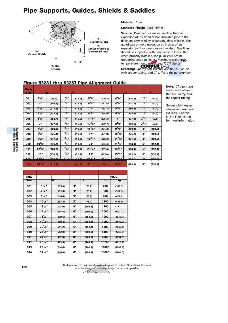
7/18/2019 PH Pipe Hanger Catalog
http://slidepdf.com/reader/full/ph-pipe-hanger-catalog 110/224
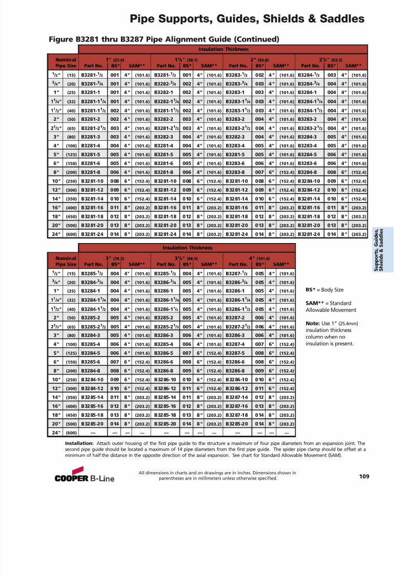
7/18/2019 PH Pipe Hanger Catalog
http://slidepdf.com/reader/full/ph-pipe-hanger-catalog 111/224
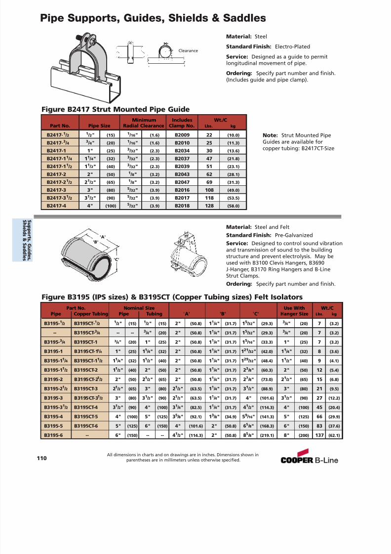
7/18/2019 PH Pipe Hanger Catalog
http://slidepdf.com/reader/full/ph-pipe-hanger-catalog 112/224
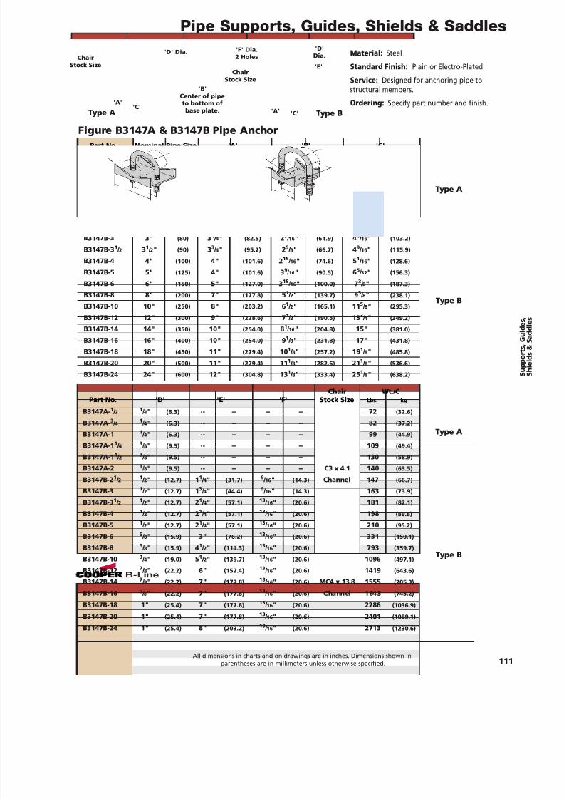
7/18/2019 PH Pipe Hanger Catalog
http://slidepdf.com/reader/full/ph-pipe-hanger-catalog 113/224
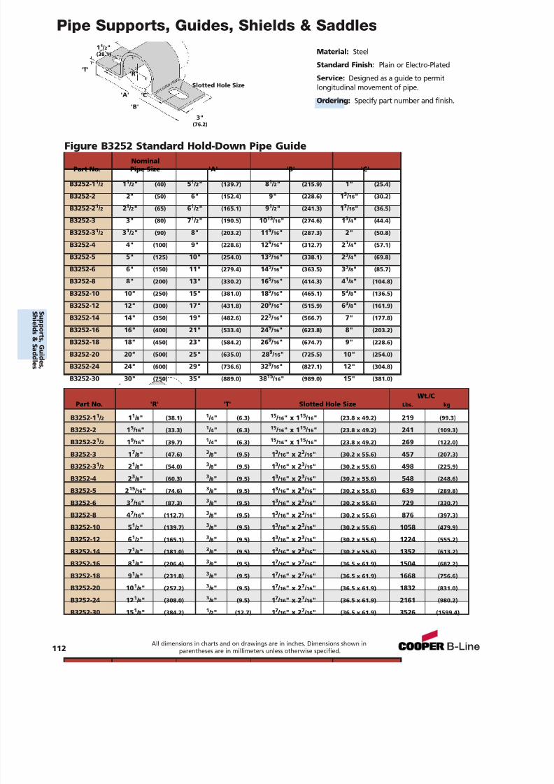
7/18/2019 PH Pipe Hanger Catalog
http://slidepdf.com/reader/full/ph-pipe-hanger-catalog 114/224
Pipe Supports, Guides, Shields & Saddles
Material: Steel
Standard Finish: Plain or Electro-Plated
Service: Designed as a guide to permitlongitudinal movement of pipe.
Ordering: Specify part number and finish.
Figure B3252 Standard Hold-Down Pipe Guide
'A'
'B'
'C'
'R''T'
3"(76.2)
1 1 / 2"(38.1)
Slotted Hole Size
NominalPart No. Pipe Size 'A' 'B' 'C'
B3252-1 1 / 2 11 / 2" (40) 51 / 2" (139.7) 81 / 2" (215.9) 1" (25.4)
B3252-2 2" (50) 6" (152.4) 9" (228.6) 13 / 16 " (30.2)
B3252-2 1 / 2 21 / 2" (65) 61 / 2" (165.1) 91 / 2" (241.3) 17 / 16 " (36.5)
B3252-3 3" (80) 71 / 2" (190.5) 10 13 / 16 " (274.6) 13 / 4" (44.4)
B3252-3 1 / 2 31 / 2" (90) 8" (203.2) 11 5 / 16 " (287.3) 2" (50.8)
B3252-4 4" (100) 9" (228.6) 12 5 / 16 " (312.7) 21 / 4" (57.1)
B3252-5 5" (125) 10" (254.0) 135
/ 16 " (338.1) 23
/ 4" (69.8)B3252-6 6" (150) 11" (279.4) 14 5 / 16 " (363.5) 33 / 8" (85.7)
B3252-8 8" (200) 13" (330.2) 16 5 / 16 " (414.3) 41 / 8" (104.8)
B3252-10 10" (250) 15" (381.0) 18 5 / 16 " (465.1) 53 / 8" (136.5)
B3252-12 12" (300) 17" (431.8) 20 5 / 16 " (515.9) 63 / 8" (161.9)
B3252-14 14" (350) 19" (482.6) 22 5 / 16 " (566.7) 7" (177.8)
B3252-16 16" (400) 21" (533.4) 24 9 / 16 " (623.8) 8" (203.2)
B3252-18 18" (450) 23" (584.2) 26 9 / 16 " (674.7) 9" (228.6)
B3252-20 20" (500) 25" (635.0) 28 9 / 16 " (725.5) 10" (254.0)
B3252-24 24" (600) 29" (736.6) 32 9 / 16 " (827.1) 12" (304.8)
B3252-30 30" (750) 35" (889.0) 38 15 / 16 " (989.0) 15" (381.0)
Wt./CPart No. 'R' 'T' Slotted Hole Size Lbs. kg
B3252-1 1 / 2 11 / 8" (38.1) 1 / 4" (6.3) 15 / 16 " x 1 15 / 16 " (23.8 x 49.2) 219 (99.3)
B3252-2 1 5 / 16 " (33.3) 1 / 4" (6.3) 15 / 16 " x 1 15 / 16 " (23.8 x 49.2) 241 (109.3)
B3252-2 1 / 2 19 / 16 " (39.7) 1 / 4" (6.3) 15 / 16 " x 1 15 / 16 " (23.8 x 49.2) 269 (122.0)
B3252-3 1 7 / 8" (47.6) 3 / 8" (9.5) 13 / 16 " x 2 3 / 16 " (30.2 x 55.6) 457 (207.3)
B3252-3 1 / 2 21 / 8" (54.0) 3 / 8" (9.5) 13 / 16 " x 2 3 / 16 " (30.2 x 55.6) 498 (225.9)
B3252-4 2 3 / 8" (60.3) 3 / 8" (9.5) 13 / 16 " x 2 3 / 16 " (30.2 x 55.6) 548 (248.6)
B3252-5 2 15 / 16 " (74.6) 3 / 8" (9.5) 13 / 16 " x 2 3 / 16 " (30.2 x 55.6) 639 (289.8)
B3252-6 3 7 / 16 " (87.3) 3 / 8" (9.5) 13 / 16 " x 2 3 / 16 " (30.2 x 55.6) 729 (330.7)
B3252-8 4 7 / 16 " (112.7) 3 / 8" (9.5) 13 / 16 " x 2 3 / 16 " (30.2 x 55.6) 876 (397.3)
B3252-10 5 1 / 2" (139.7) 3 / 8" (9.5) 13 / 16 " x 2 3 / 16 " (30.2 x 55.6) 1058 (479.9)
B3252-12 6 1 / 2" (165.1) 3 / 8" (9.5) 13 / 16 " x 2 3 / 16 " (30.2 x 55.6) 1224 (555.2)
B3252-14 7 1 / 8" (181.0) 3 / 8" (9.5) 13 / 16 " x 2 3 / 16 " (30.2 x 55.6) 1352 (613.2)
B3252-16 8 1 / 8" (206.4) 3 / 8" (9.5) 17 / 16 " x 2 7 / 16 " (36.5 x 61.9) 1504 (682.2)
B3252-18 9 1 / 8" (231.8) 3 / 8" (9.5) 17 / 16 " x 2 7 / 16 " (36.5 x 61.9) 1668 (756.6)
B3252-20 10 1 / 8" (257.2) 3 / 8" (9.5) 17 / 16 " x 2 7 / 16 " (36.5 x 61.9) 1832 (831.0)
B3252-24 12 1 / 8" (308.0) 3 / 8" (9.5) 17 / 16 " x 2 7 / 16 " (36.5 x 61.9) 2161 (980.2)
B3252-30 15 1 / 8" (384.2) 1 / 2" (12.7) 17 / 16 " x 2 7 / 16 " (36.5 x 61.9) 3526 (1599.4)
112All dimensions in charts and on drawings are in inches. Dimensions shown in
parentheses are in millimeters unless otherwise specified.
S uppor t s ,Gui d es ,
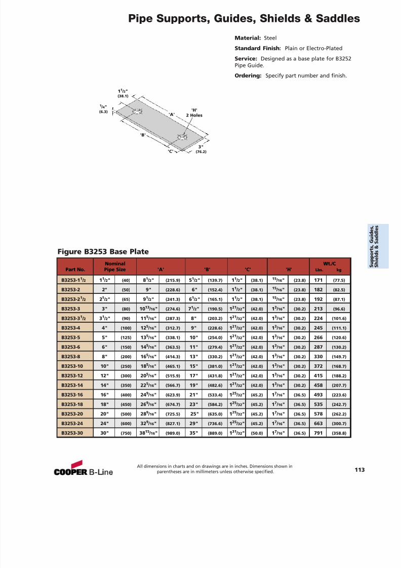
7/18/2019 PH Pipe Hanger Catalog
http://slidepdf.com/reader/full/ph-pipe-hanger-catalog 115/224
Pipe Supports, Guides, Shields & Saddles
Material: Steel
Standard Finish: Plain or Electro-Plated
Service: Designed as a base plate for B3252Pipe Guide.
Ordering: Specify part number and finish.
Figure B3253 Base Plate
'A'
'B'
'C'3"
(76.2)
1 1 / 2"(38.1)
1 / 4"(6.3) 'H'
2 Holes
Nominal Wt./CPart No. Pipe Size 'A' 'B' 'C' 'H' Lbs. kg
B3253-11
/ 2 11
/ 2" (40) 81
/ 2" (215.9) 51
/ 2" (139.7) 11
/ 2" (38.1)15
/ 16 " (23.8) 171 (77.5)B3253-2 2" (50) 9" (228.6) 6" (152.4) 11 / 2" (38.1) 15 / 16 " (23.8) 182 (82.5)
B3253-2 1 / 2 21 / 2" (65) 91 / 2" (241.3) 61 / 2" (165.1) 11 / 2" (38.1) 15 / 16 " (23.8) 192 (87.1)
B3253-3 3" (80) 10 13 / 16 " (274.6) 71 / 2" (190.5) 121 / 32 " (42.0) 13 / 16 " (30.2) 213 (96.6)
B3253-3 1 / 2 31 / 2" (90) 11 5 / 16 " (287.3) 8" (203.2) 121 / 32 " (42.0) 13 / 16 " (30.2) 224 (101.6)
B3253-4 4" (100) 12 5 / 16 " (312.7) 9" (228.6) 121 / 32 " (42.0) 13 / 16 " (30.2) 245 (111.1)
B3253-5 5" (125) 13 5 / 16 " (338.1) 10" (254.0) 121 / 32 " (42.0) 13 / 16 " (30.2) 266 (120.6)
B3253-6 6" (150) 14 5 / 16 " (363.5) 11" (279.4) 121 / 32 " (42.0) 13 / 16 " (30.2) 287 (130.2)
B3253-8 8" (200) 16 5 / 16 " (414.3) 13" (330.2) 121 / 32 " (42.0) 13 / 16 " (30.2) 330 (149.7)
B3253-10 10" (250) 18 5 / 16 " (465.1) 15" (381.0) 121 / 32 " (42.0) 13 / 16 " (30.2) 372 (168.7)
B3253-12 12" (300) 20 5 / 16 " (515.9) 17" (431.8) 121 / 32 " (42.0) 13 / 16 " (30.2) 415 (188.2)
B3253-14 14" (350) 22 5 / 16 " (566.7) 19" (482.6) 121 / 32 " (42.0) 13 / 16 " (30.2) 458 (207.7)
B3253-16 16" (400) 24 9 / 16 " (623.9) 21" (533.4) 125 / 32 " (45.2) 17 / 16 " (36.5) 493 (223.6)
B3253-18 18" (450) 26 9 / 16 " (674.7) 23" (584.2) 125 / 32 " (45.2) 17 / 16 " (36.5) 535 (242.7)
B3253-20 20" (500) 28 9 / 16 " (725.5) 25" (635.0) 125 / 32 " (45.2) 17 / 16 " (36.5) 578 (262.2)
B3253-24 24" (600) 32 9 / 16 " (827.1) 29" (736.6) 125 / 32 " (45.2) 17 / 16 " (36.5) 663 (300.7)
B3253-30 30" (750) 38 15 / 16 " (989.0) 35" (889.0) 131 / 32 " (50.0) 17 / 16 " (36.5) 791 (358.8)
All dimensions in charts and on drawings are in inches. Dimensions shown inparentheses are in millimeters unless otherwise specified. 113
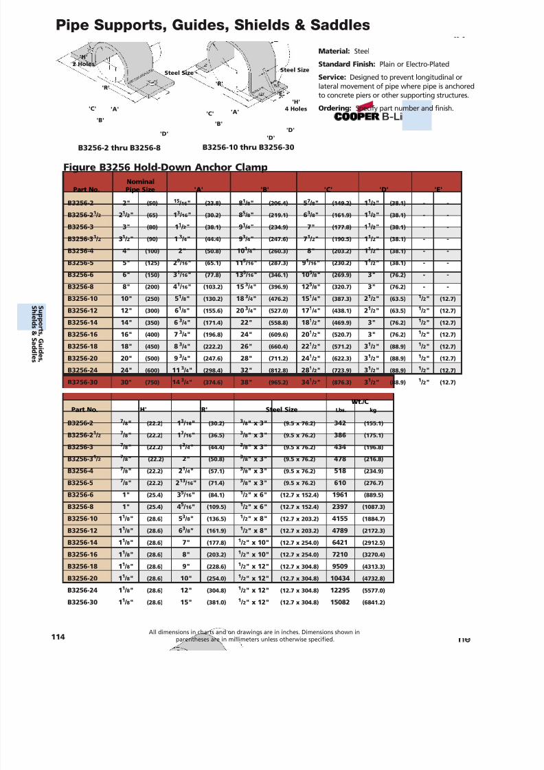
7/18/2019 PH Pipe Hanger Catalog
http://slidepdf.com/reader/full/ph-pipe-hanger-catalog 116/224
Pipe Supports, Guides, Shields & Saddles
Material: Steel
Standard Finish: Plain or Electro-Plated
Service: Designed to prevent longitudinal orlateral movement of pipe where pipe is anchoredto concrete piers or other supporting structures.
Ordering: Specify part number and finish.
Figure B3256 Hold-Down Anchor Clamp
'A'
'R''R'
'E'
'B'
'C'
B3256-2 thru B3256-8 B3256-10 thru B3256-30
'A'
'D''D'
'D'
'B'
'C'
Steel Size Steel Size
'H'2 Holes
'H'4 Holes
NominalPart No. Pipe Size 'A' 'B' 'C' 'D' 'E'
B3256-2 2" (50) 15 / 16 " (23.8) 81 / 8" (206.4) 57 / 8" (149.2) 11 / 2" (38.1) - -
B3256-2 1 / 2 21 / 2" (65) 13 / 16 " (30.2) 85 / 8" (219.1) 63 / 8" (161.9) 11 / 2" (38.1) - -
B3256-3 3" (80) 11 / 2" (38.1) 91 / 4" (234.9) 7" (177.8) 11 / 2" (38.1) - -
B3256-3 1 / 2 31 / 2" (90) 1 3 / 4" (44.4) 93 / 4" (247.6) 71 / 2" (190.5) 11 / 2" (38.1) - -
B3256-4 4" (100) 2" (50.8) 10 1 / 4" (260.3) 8" (203.2) 11 / 2" (38.1) - -
B3256-5 5" (125) 29 / 16 " (65.1) 11 5 / 16 " (287.3) 91 / 16 " (230.2) 11 / 2" (38.1) - -
B3256-6 6" (150) 31 / 16 " (77.8) 13 9 / 16 " (346.1) 10 5 / 8" (269.9) 3" (76.2) - -
B3256-8 8" (200) 41 / 16 " (103.2) 15 3 / 4" (396.9) 12 5 / 8" (320.7) 3" (76.2) - -
B3256-10 10" (250) 51 / 8" (130.2) 18 3 / 4" (476.2) 15 1 / 4" (387.3) 21 / 2" (63.5) 1 / 2" (12.7)
B3256-12 12" (300) 61 / 8" (155.6) 20 3 / 4" (527.0) 17 1 / 4" (438.1) 21 / 2" (63.5) 1 / 2" (12.7)
B3256-14 14" (350) 6 3 / 4" (171.4) 22" (558.8) 18 1 / 2" (469.9) 3" (76.2) 1 / 2" (12.7)
B3256-16 16" (400) 7 3 / 4" (196.8) 24" (609.6) 20 1 / 2" (520.7) 3" (76.2) 1 / 2" (12.7)
B3256-18 18" (450) 8 3 / 4" (222.2) 26" (660.4) 22 1 / 2" (571.2) 31 / 2" (88.9) 1 / 2" (12.7)
B3256-20 20" (500) 9 3 / 4" (247.6) 28" (711.2) 24 1 / 2" (622.3) 31 / 2" (88.9) 1 / 2" (12.7)
B3256-24 24" (600) 11 3 / 4" (298.4) 32" (812.8) 28 1 / 2" (723.9) 31 / 2" (88.9) 1 / 2" (12.7)
B3256-30 30" (750) 14 3 / 4" (374.6) 38" (965.2) 34 1 / 2" (876.3) 31 / 2" (88.9) 1 / 2" (12.7)
Wt./CPart No. 'H' 'R' Steel Size Lbs. kg
B3256-2 7 / 8" (22.2) 13 / 16 " (30.2) 3 / 8" x 3" (9.5 x 76.2) 342 (155.1)
B3256-2 1 / 2 7 / 8" (22.2) 17 / 16 " (36.5) 3 / 8" x 3" (9.5 x 76.2) 386 (175.1)
B3256-3 7 / 8" (22.2) 13 / 4" (44.4) 3 / 8" x 3" (9.5 x 76.2) 434 (196.8)
B3256-3 1 / 2 7 / 8" (22.2) 2" (50.8) 3 / 8" x 3" (9.5 x 76.2) 478 (216.8)
B3256-4 7 / 8" (22.2) 21 / 4" (57.1) 3 / 8" x 3" (9.5 x 76.2) 518 (234.9)
B3256-5 7 / 8" (22.2) 213 / 16 " (71.4) 3 / 8" x 3" (9.5 x 76.2) 610 (276.7)
B3256-6 1" (25.4) 35 / 16 " (84.1) 1 / 2" x 6" (12.7 x 152.4) 1961 (889.5)
B3256-8 1" (25.4) 45
/ 16 " (109.5)1
/ 2" x 6" (12.7 x 152.4) 2397 (1087.3)B3256-10 1 1 / 8" (28.6) 53 / 8" (136.5) 1 / 2" x 8" (12.7 x 203.2) 4155 (1884.7)
B3256-12 1 1 / 8" (28.6) 63 / 8" (161.9) 1 / 2" x 8" (12.7 x 203.2) 4789 (2172.3)
B3256-14 1 1 / 8" (28.6) 7" (177.8) 1 / 2" x 10" (12.7 x 254.0) 6421 (2912.5)
B3256-16 1 1 / 8" (28.6) 8" (203.2) 1 / 2" x 10" (12.7 x 254.0) 7210 (3270.4)
B3256-18 1 1 / 8" (28.6) 9" (228.6) 1 / 2" x 12" (12.7 x 304.8) 9509 (4313.3)
B3256-20 1 1 / 8" (28.6) 10" (254.0) 1 / 2" x 12" (12.7 x 304.8) 10434 (4732.8)
B3256-24 1 1 / 8" (28.6) 12" (304.8) 1 / 2" x 12" (12.7 x 304.8) 12295 (5577.0)
B3256-30 1 1 / 8" (28.6) 15" (381.0) 1 / 2" x 12" (12.7 x 304.8) 15082 (6841.2)
114All dimensions in charts and on drawings are in inches. Dimensions shown in
parentheses are in millimeters unless otherwise specified.
S uppor t s ,Gui d es ,
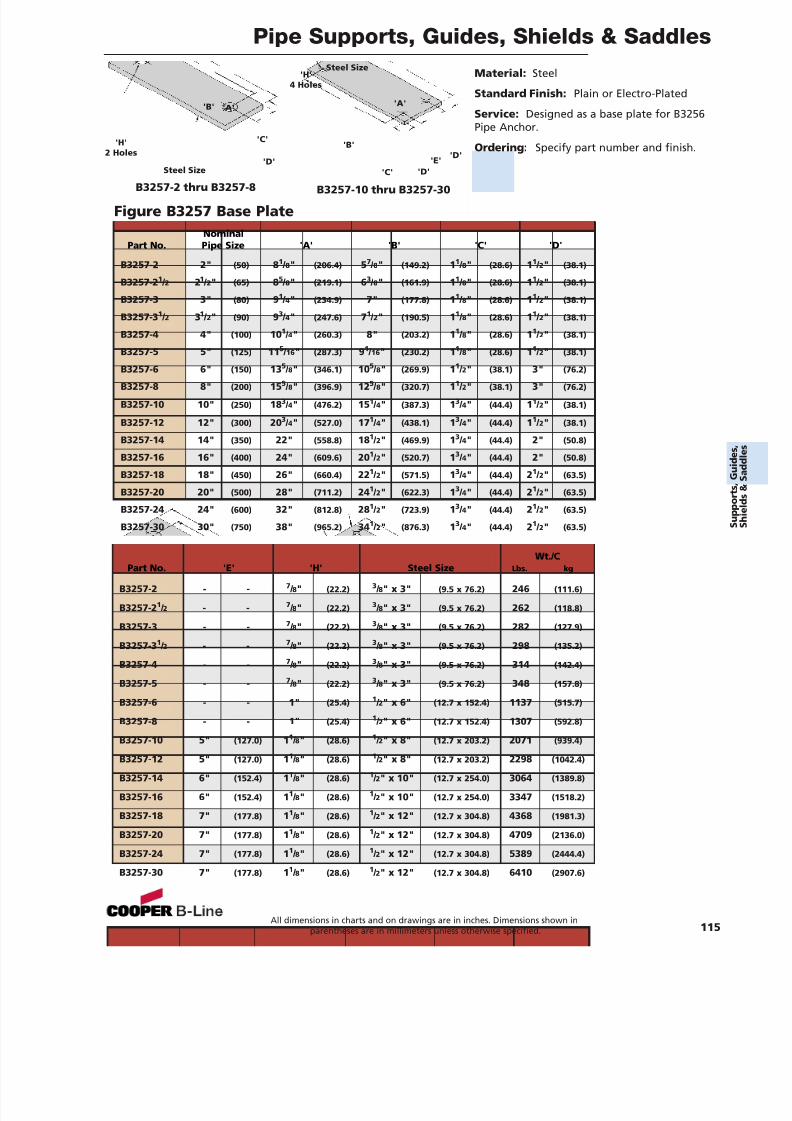
7/18/2019 PH Pipe Hanger Catalog
http://slidepdf.com/reader/full/ph-pipe-hanger-catalog 117/224
Pipe Supports, Guides, Shields & Saddles
Material: Steel
Standard Finish: Plain or Electro-Plated
Service: Designed as a base plate for B3256Pipe Anchor.
Ordering: Specify part number and finish.
Figure B3257 Base Plate
'A''B'
'C'
B3257-2 thru B3257-8 B3257-10 thru B3257-30
'A'
'D'
'D''D'
'B'
'C'Steel Size
Steel Size
'H'2 Holes
'H'4 Holes
'E'
NominalPart No. Pipe Size 'A' 'B' 'C' 'D'
B3257-2 2" (50) 81 / 8" (206.4) 57 / 8" (149.2) 11 / 8" (28.6) 11 / 2" (38.1)
B3257-2 1 / 2 21 / 2" (65) 85 / 8" (219.1) 63 / 8" (161.9) 11 / 8" (28.6) 11 / 2" (38.1)
B3257-3 3" (80) 91 / 4" (234.9) 7" (177.8) 11 / 8" (28.6) 11 / 2" (38.1)
B3257-3 1 / 2 31 / 2" (90) 93 / 4" (247.6) 71 / 2" (190.5) 11 / 8" (28.6) 11 / 2" (38.1)
B3257-4 4" (100) 10 1 / 4" (260.3) 8" (203.2) 11 / 8" (28.6) 11 / 2" (38.1)
B3257-5 5" (125) 11 5 / 16 " (287.3) 91 / 16 " (230.2) 11 / 8" (28.6) 11 / 2" (38.1)
B3257-6 6" (150) 135 / 8" (346.1) 10
5 / 8" (269.9) 1
1 / 2" (38.1) 3" (76.2)
B3257-8 8" (200) 15 5 / 8" (396.9) 12 5 / 8" (320.7) 11 / 2" (38.1) 3" (76.2)
B3257-10 10" (250) 18 3 / 4" (476.2) 15 1 / 4" (387.3) 13 / 4" (44.4) 11 / 2" (38.1)
B3257-12 12" (300) 20 3 / 4" (527.0) 17 1 / 4" (438.1) 13 / 4" (44.4) 11 / 2" (38.1)
B3257-14 14" (350) 22" (558.8) 18 1 / 2" (469.9) 13 / 4" (44.4) 2" (50.8)
B3257-16 16" (400) 24" (609.6) 20 1 / 2" (520.7) 13 / 4" (44.4) 2" (50.8)
B3257-18 18" (450) 26" (660.4) 22 1 / 2" (571.5) 13 / 4" (44.4) 21 / 2" (63.5)
B3257-20 20" (500) 28" (711.2) 24 1 / 2" (622.3) 13 / 4" (44.4) 21 / 2" (63.5)
B3257-24 24" (600) 32" (812.8) 28 1 / 2" (723.9) 13 / 4" (44.4) 21 / 2" (63.5)
B3257-30 30" (750) 38" (965.2) 34 1 / 2" (876.3) 13 / 4" (44.4) 21 / 2" (63.5)
Wt./CPart No. 'E' 'H' Steel Size Lbs. kg
B3257-2 - - 7 / 8" (22.2) 3 / 8" x 3" (9.5 x 76.2) 246 (111.6)
B3257-2 1 / 2 - - 7 / 8" (22.2) 3 / 8" x 3" (9.5 x 76.2) 262 (118.8)
B3257-3 - - 7 / 8" (22.2) 3 / 8" x 3" (9.5 x 76.2) 282 (127.9)
B3257-3 1 / 2 - - 7 / 8" (22.2) 3 / 8" x 3" (9.5 x 76.2) 298 (135.2)
B3257-4 - - 7 / 8" (22.2) 3 / 8" x 3" (9.5 x 76.2) 314 (142.4)
B3257-5 - - 7 / 8" (22.2) 3 / 8" x 3" (9.5 x 76.2) 348 (157.8)
B3257-6 - - 1" (25.4) 1 / 2" x 6" (12.7 x 152.4) 1137 (515.7)
B3257-8 - - 1" (25.4) 1 / 2" x 6" (12.7 x 152.4) 1307 (592.8)
B3257-10 5" (127.0) 11 / 8" (28.6)
1 / 2" x 8" (12.7 x 203.2) 2071 (939.4)
B3257-12 5" (127.0) 11 / 8" (28.6) 1 / 2" x 8" (12.7 x 203.2) 2298 (1042.4)
B3257-14 6" (152.4) 11 / 8" (28.6) 1 / 2" x 10" (12.7 x 254.0) 3064 (1389.8)
B3257-16 6" (152.4) 11 / 8" (28.6) 1 / 2" x 10" (12.7 x 254.0) 3347 (1518.2)
B3257-18 7" (177.8) 11 / 8" (28.6) 1 / 2" x 12" (12.7 x 304.8) 4368 (1981.3)
B3257-20 7" (177.8) 11 / 8" (28.6) 1 / 2" x 12" (12.7 x 304.8) 4709 (2136.0)
B3257-24 7" (177.8) 11 / 8" (28.6) 1 / 2" x 12" (12.7 x 304.8) 5389 (2444.4)
B3257-30 7" (177.8) 11 / 8" (28.6) 1 / 2" x 12" (12.7 x 304.8) 6410 (2907.6)
All dimensions in charts and on drawings are in inches. Dimensions shown inparentheses are in millimeters unless otherwise specified. 115
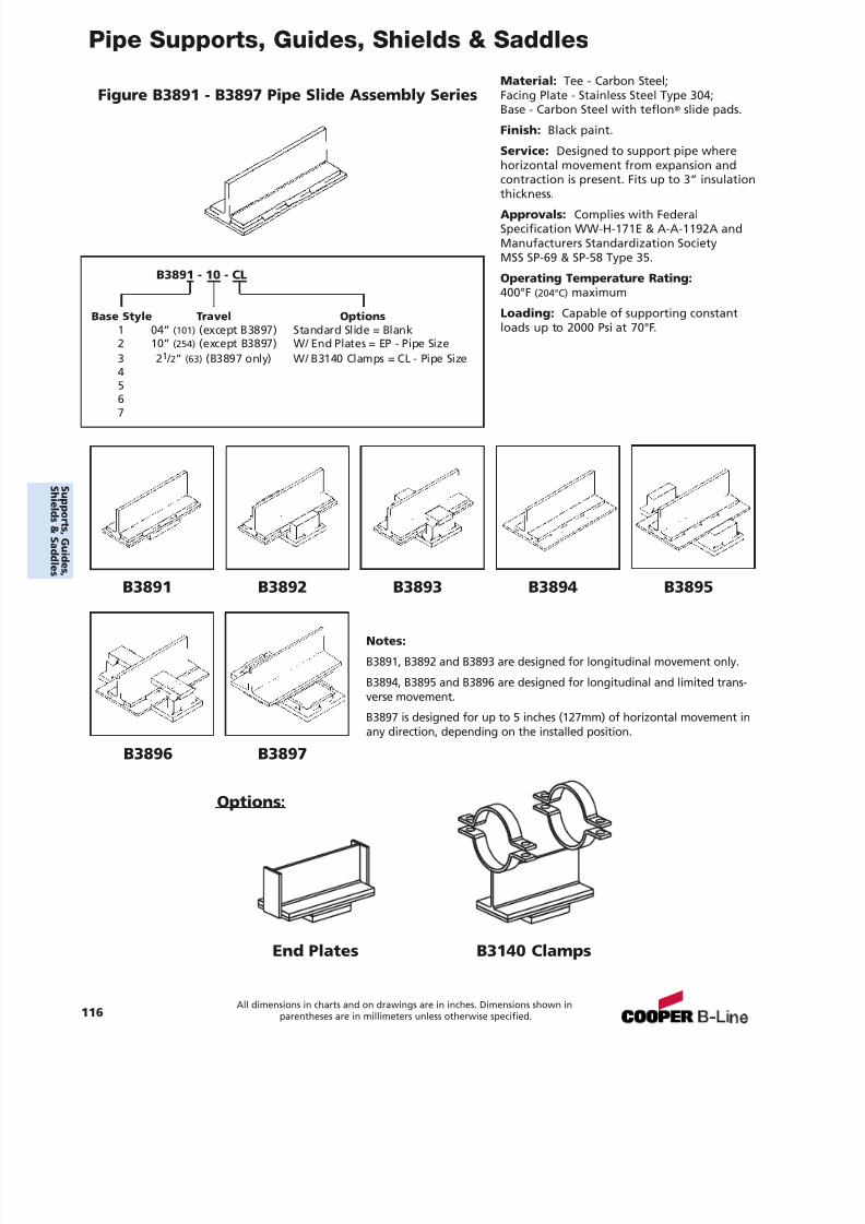
7/18/2019 PH Pipe Hanger Catalog
http://slidepdf.com/reader/full/ph-pipe-hanger-catalog 118/224
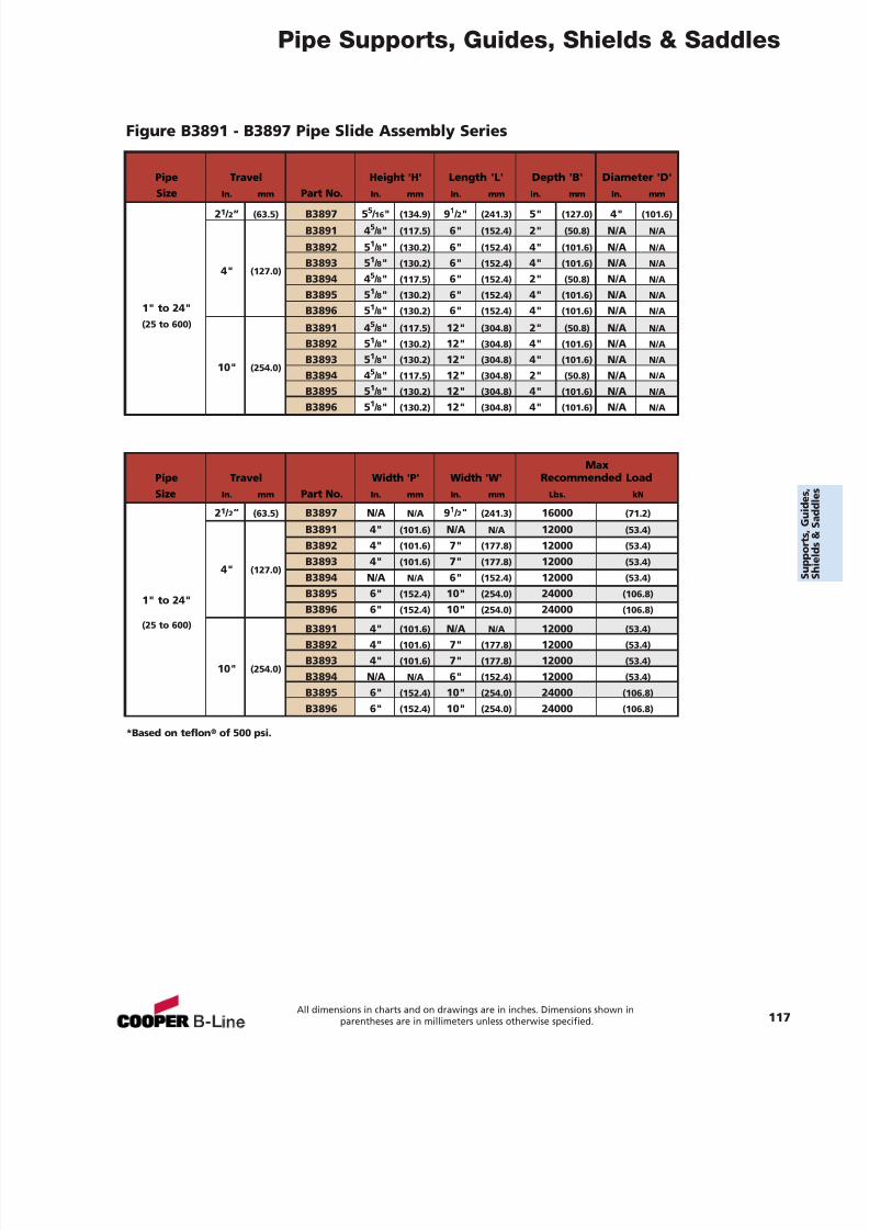
7/18/2019 PH Pipe Hanger Catalog
http://slidepdf.com/reader/full/ph-pipe-hanger-catalog 119/224
Pipe Supports, Guides, Shields & Saddles
*Based on teflon ® of 500 psi.
Figure B3891 - B3897 Pipe Slide Assembly Series
Pipe Travel Height 'H' Length 'L' Depth 'B' Diameter 'D'Size In. mm Part No. In. mm In. mm In. mm In. mm
21 / 2” (63.5) B3897 5 5 / 16 " (134.9) 91 / 2" (241.3) 5" (127.0) 4" (101.6)
B3891 4 5 / 8" (117.5) 6" (152.4) 2" (50.8) N/A N/A
B3892 5 1 / 8" (130.2) 6" (152.4) 4" (101.6) N/A N/A
B3893 5 1 / 8" (130.2) 6" (152.4) 4" (101.6) N/A N/A4" (127.0)
B3894 4 5 / 8" (117.5) 6" (152.4) 2" (50.8) N/A N/A
B3895 5 1 / 8" (130.2) 6" (152.4) 4" (101.6) N/A N/A1" to 24" B3896 5 1 / 8" (130.2) 6" (152.4) 4" (101.6) N/A N/A(25 to 600) B3891 4 5 / 8" (117.5) 12" (304.8) 2" (50.8) N/A N/A
B3892 5 1 / 8" (130.2) 12" (304.8) 4" (101.6) N/A N/A
B3893 5 1 / 8" (130.2) 12" (304.8) 4" (101.6) N/A N/A10" (254.0)
B3894 4 5 / 8" (117.5) 12" (304.8) 2" (50.8) N/A N/A
B3895 5 1 / 8" (130.2) 12" (304.8) 4" (101.6) N/A N/A
B3896 5 1 / 8" (130.2) 12" (304.8) 4" (101.6) N/A N/A
MaxPipe Travel Width 'P' Width 'W' Recommended LoadSize In. mm Part No. In. mm In. mm Lbs. kN
21 / 2” (63.5) B3897 N/A N/A 91 / 2" (241.3) 16000 (71.2)
B3891 4" (101.6) N/A N/A 12000 (53.4)
B3892 4" (101.6) 7" (177.8) 12000 (53.4)
B3893 4" (101.6) 7" (177.8) 12000 (53.4)4" (127.0)
B3894 N/A N/A 6" (152.4) 12000 (53.4)
B3895 6" (152.4) 10" (254.0) 24000 (106.8)1" to 24"B3896 6" (152.4) 10" (254.0) 24000 (106.8)
(25 to 600) B3891 4" (101.6) N/A N/A 12000 (53.4)
B3892 4" (101.6) 7" (177.8) 12000 (53.4)
B3893 4" (101.6) 7" (177.8) 12000 (53.4)10" (254.0)
B3894 N/A N/A 6" (152.4) 12000 (53.4)
B3895 6" (152.4) 10" (254.0) 24000 (106.8)
B3896 6" (152.4) 10" (254.0) 24000 (106.8)
All dimensions in charts and on drawings are in inches. Dimensions shown inparentheses are in millimeters unless otherwise specified. 117
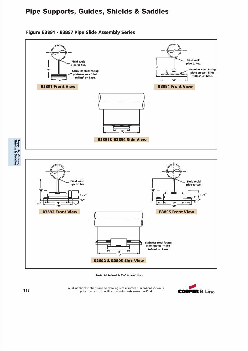
7/18/2019 PH Pipe Hanger Catalog
http://slidepdf.com/reader/full/ph-pipe-hanger-catalog 120/224
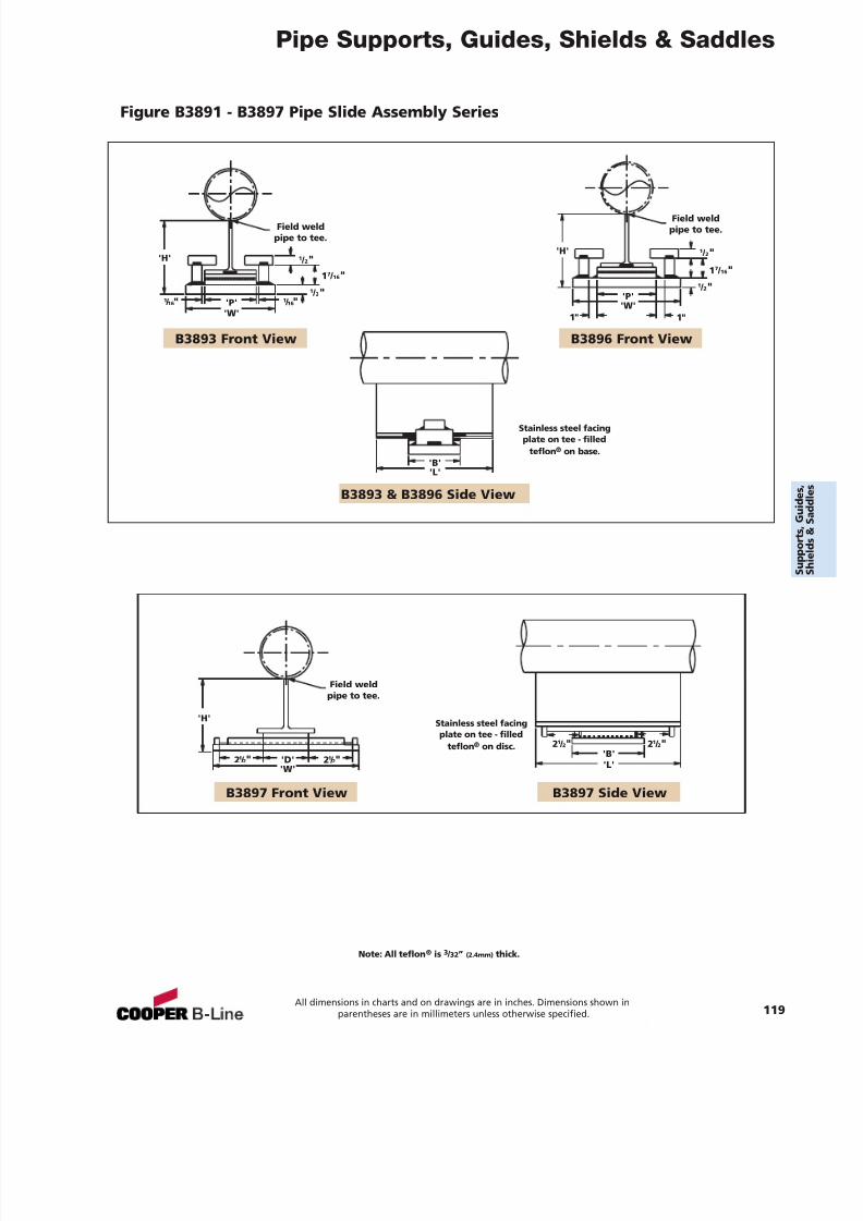
7/18/2019 PH Pipe Hanger Catalog
http://slidepdf.com/reader/full/ph-pipe-hanger-catalog 121/224
Pipe Supports, Guides, Shields & Saddles
B3893 Front View B3896 Front View
B3893 & B3896 Side View
B3897 Side View
'H''H'
'P''W'
'P''W'
'B''L'
1"
1 7 / 16 "
1 / 2"1 / 16"
1 / 2"
'B''L'
21 / 2"
B3897 Front View
'H'
'D''W'
Field weldpipe to tee.
Field weldpipe to tee.
Field weldpipe to tee.
Stainless steel facingplate on tee - filled
teflon ® on base.
Figure B3891 - B3897 Pipe Slide Assembly Series
Note: All teflon ® is 3 / 32” (2.4mm) thick.
1 / 2"1 7 / 16 "
1 / 16"1"
1 / 2"
21 / 2"21 / 2" 21 / 2"
Stainless steel facingplate on tee - filled
teflon ® on disc.
All dimensions in charts and on drawings are in inches. Dimensions shown inparentheses are in millimeters unless otherwise specified. 119
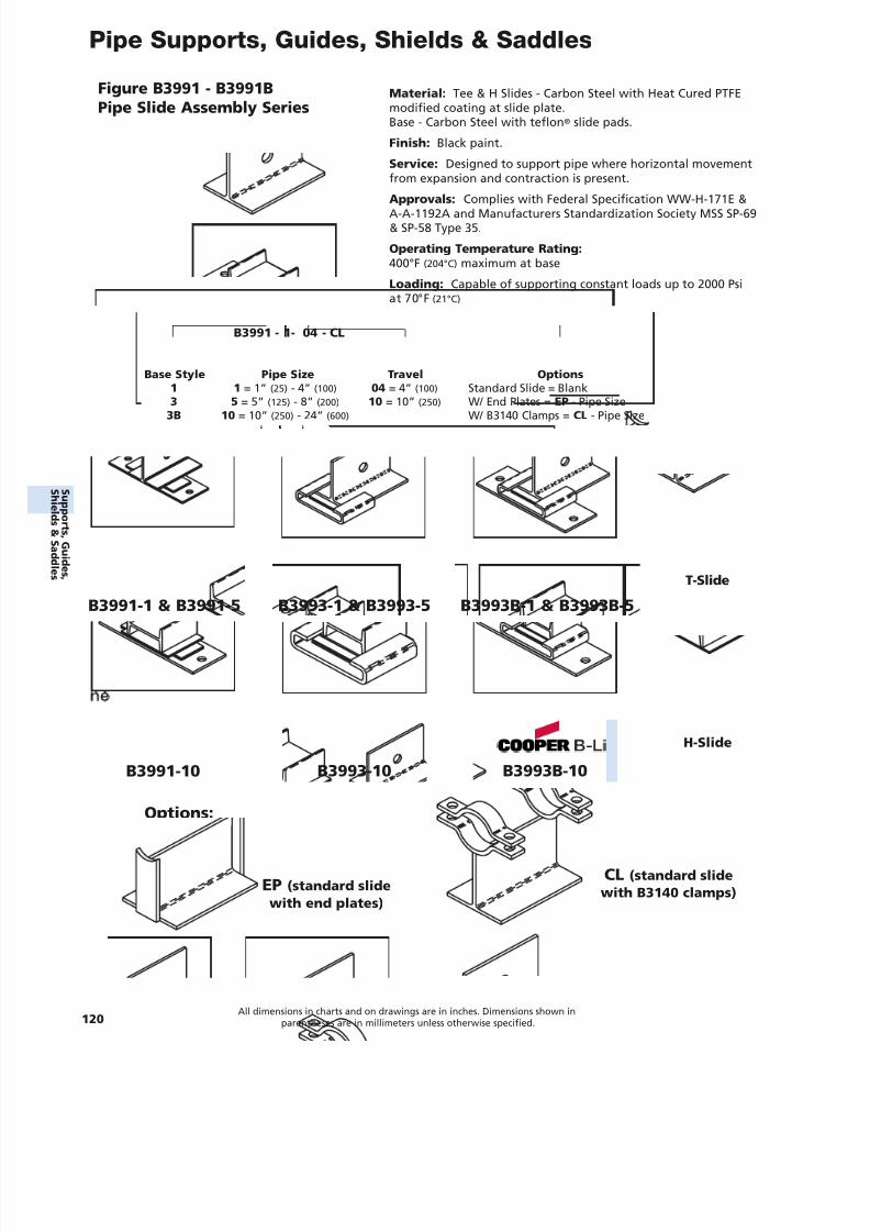
7/18/2019 PH Pipe Hanger Catalog
http://slidepdf.com/reader/full/ph-pipe-hanger-catalog 122/224
Pipe Supports, Guides, Shields & Saddles
120All dimensions in charts and on drawings are in inches. Dimensions shown in
parentheses are in millimeters unless otherwise specified.
Figure B3991 - B3991BPipe Slide Assembly Series
Material: Tee & H Slides - Carbon Steel with Heat Cured PTFEmodified coating at slide plate.Base - Carbon Steel with teflon ® slide pads.
Finish: Black paint.
Service: Designed to support pipe where horizontal movementfrom expansion and contraction is present.
Approvals: Complies with Federal Specification WW-H-171E &A-A-1192A and Manufacturers Standardization Society MSS SP-69& SP-58 Type 35.
Operating Temperature Rating:400°F (204°C) maximum at base
Loading: Capable of supporting constant loads up to 2000 Psiat 70°F (21°C)
B3991-1 & B3991-5 B3993-1 & B3993-5
B3991-10 B3993-10
B3993B-1 & B3993B-5
B3993B-10
Options:
EP (standard slidewith end plates)
CL (standard slidewith B3140 clamps)
T-Slide
H-Slide
B3991 - 1- 04 - CL
Base Style Pipe Size Travel Options1 1 = 1” (25) - 4” (100) 04 = 4” (100) Standard Slide = Blank
3 5 = 5” (125) - 8” (200) 10 = 10” (250) W/ End Plates = EP - Pipe Size3B 10 = 10” (250) - 24” (600) W/ B3140 Clamps = CL - Pipe Size
S uppor t s ,Gui d es ,
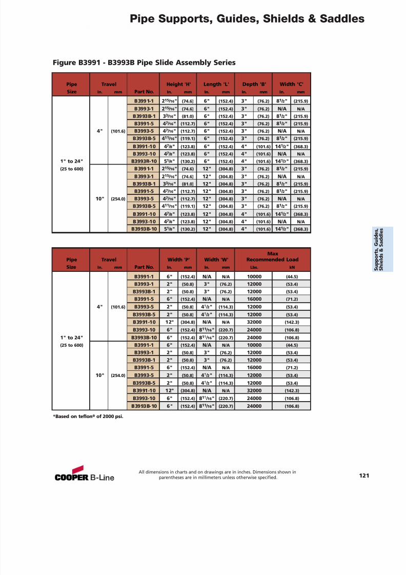
7/18/2019 PH Pipe Hanger Catalog
http://slidepdf.com/reader/full/ph-pipe-hanger-catalog 123/224
Pipe Supports, Guides, Shields & Saddles
All dimensions in charts and on drawings are in inches. Dimensions shown inparentheses are in millimeters unless otherwise specified. 121
*Based on teflon ® of 2000 psi.
Figure B3991 - B3993B Pipe Slide Assembly Series
Pipe Travel Height 'H' Length 'L' Depth 'B' Width 'C'Size In. mm Part No. In. mm In. mm In. mm In. mm
B3991-1 2 15 / 16 " (74.6) 6" (152.4) 3" (76.2) 81 / 2" (215.9)
B3993-1 2 15 / 16 " (74.6) 6" (152.4) 3" (76.2) N/A N/A
B3993B-1 3 3 / 16 " (81.0) 6" (152.4) 3" (76.2) 81 / 2" (215.9)
B3991-5 4 7 / 16 " (112.7) 6" (152.4) 3" (76.2) 81 / 2" (215.9)
4" (101.6) B3993-5 4 7 / 16 " (112.7) 6" (152.4) 3" (76.2) N/A N/A
B3993B-5 4 11 / 16 " (119.1) 6" (152.4) 3" (76.2) 81 / 2" (215.9)
B3991-10 4 7 / 8" (123.8) 6" (152.4) 4" (101.6) 14 1 / 2" (368.3)
B3993-10 4 7 / 8" (123.8) 6" (152.4) 4" (101.6) N/A N/A
1" to 24" B3993B-10 5 1 / 8" (130.2) 6" (152.4) 4" (101.6) 14 1 / 2" (368.3)
(25 to 600) B3991-1 2 15 / 16 " (74.6) 12" (304.8) 3" (76.2) 81 / 2" (215.9)
B3993-1 2 15 / 16 " (74.6) 12" (304.8) 3" (76.2) N/A N/A
B3993B-1 3 3 / 16 " (81.0) 12" (304.8) 3" (76.2) 81 / 2" (215.9)
B3991-5 4 7 / 16 " (112.7) 12" (304.8) 3" (76.2) 81 / 2" (215.9)10" (254.0) B3993-5 4 7 / 16 " (112.7) 12" (304.8) 3" (76.2) N/A N/A
B3993B-5 4 11 / 16 " (119.1) 12" (304.8) 3" (76.2) 81 / 2" (215.9)
B3991-10 4 7 / 8" (123.8) 12" (304.8) 4" (101.6) 14 1 / 2" (368.3)
B3993-10 4 7 / 8" (123.8) 12" (304.8) 4" (101.6) N/A N/A
B3993B-10 5 1 / 8" (130.2) 12" (304.8) 4" (101.6) 14 1 / 2" (368.3)
MaxPipe Travel Width 'P' Width 'W' Recommended LoadSize In. mm Part No. In. mm In. mm Lbs. kN
B3991-1 6" (152.4) N/A N/A 10000 (44.5)
B3993-1 2" (50.8) 3" (76.2) 12000 (53.4)B3993B-1 2" (50.8) 3" (76.2) 12000 (53.4)
B3991-5 6" (152.4) N/A N/A 16000 (71.2)
4" (101.6) B3993-5 2" (50.8) 41 / 2" (114.3) 12000 (53.4)
B3993B-5 2" (50.8) 41 / 2" (114.3) 12000 (53.4)
B3991-10 12" (304.8) N/A N/A 32000 (142.3)
B3993-10 6" (152.4) 811 / 16 " (220.7) 24000 (106.8)
1" to 24" B3993B-10 6" (152.4) 811 / 16 " (220.7) 24000 (106.8)
(25 to 600) B3991-1 6" (152.4) N/A N/A 10000 (44.5)
B3993-1 2" (50.8) 3" (76.2) 12000 (53.4)
B3993B-1 2" (50.8) 3" (76.2) 12000 (53.4)
B3991-5 6" (152.4) N/A N/A 16000 (71.2)
10" (254.0) B3993-5 2" (50.8) 41 / 2" (114.3) 12000 (53.4)
B3993B-5 2" (50.8) 41 / 2" (114.3) 12000 (53.4)
B3991-10 12" (304.8) N/A N/A 32000 (142.3)
B3993-10 6" (152.4) 811 / 16 " (220.7) 24000 (106.8)
B3993B-10 6" (152.4) 811 / 16 " (220.7) 24000 (106.8)
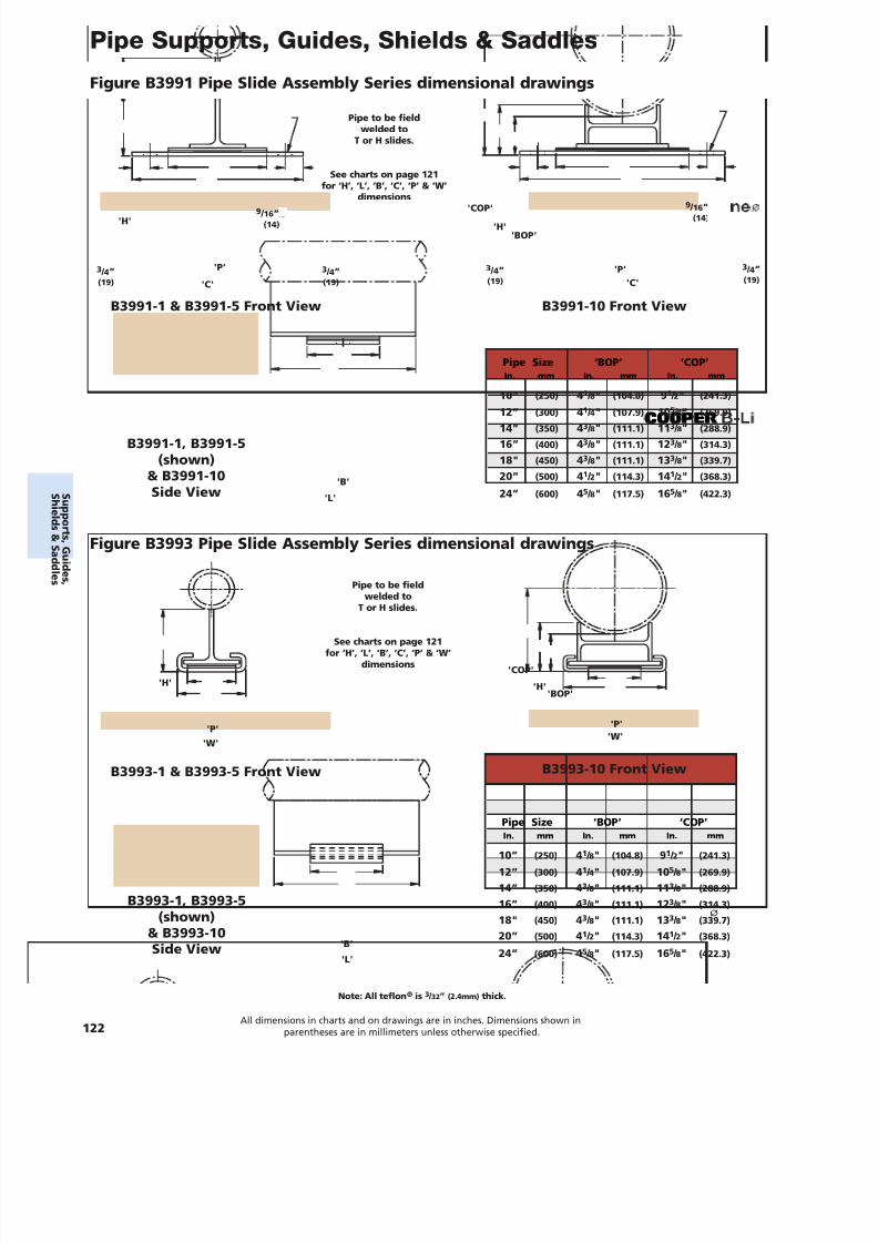
7/18/2019 PH Pipe Hanger Catalog
http://slidepdf.com/reader/full/ph-pipe-hanger-catalog 124/224
Pipe Supports, Guides, Shields & Saddles
122All dimensions in charts and on drawings are in inches. Dimensions shown in
parentheses are in millimeters unless otherwise specified.
B3991-1 & B3991-5 Front View B3991-10 Front View
B3991-1, B3991-5(shown)
& B3991-10Side View
'P'
'C'
'P''C'
'H' 'H'
'B'
'L'
'COP'
'BOP'
3 / 4”(19)
3 / 4”(19)
9 / 16 ”(14)
9 / 16 ”(14)
3 / 4”(19)
3 / 4”(19)
Figure B3991 Pipe Slide Assembly Series dimensional drawings
Figure B3993 Pipe Slide Assembly Series dimensional drawings
Note: All teflon ® is 3 / 32” (2.4mm) thick.
Pipe Size ‘BOP‘ ‘COP’In. mm In. mm In. mm
10” (250) 41 / 8" (104.8) 91 / 2" (241.3)
12” (300) 41 / 4" (107.9) 10 5 / 8" (269.9)14” (350) 43 / 8" (111.1) 11 3 / 8" (288.9)
16” (400) 43 / 8" (111.1) 12 3 / 8" (314.3)
18" (450) 43 / 8" (111.1) 13 3 / 8" (339.7)
20” (500) 41 / 2" (114.3) 14 1 / 2" (368.3)
24” (600) 45 / 8" (117.5) 16 5 / 8" (422.3)
B3993-1 & B3993-5 Front View B3993-10 Front View
'P''W'
'P''W'
'H'
'B'
'L'
'COP'
Pipe Size ‘BOP‘ ‘COP’In. mm In. mm In. mm
10” (250) 41 / 8" (104.8) 91 / 2" (241.3)
12” (300) 41 / 4" (107.9) 10 5 / 8" (269.9)
14” (350) 43 / 8" (111.1) 11 3 / 8" (288.9)
16” (400) 43 / 8" (111.1) 12 3 / 8" (314.3)
18" (450) 43 / 8" (111.1) 13 3 / 8" (339.7)
20” (500) 41 / 2" (114.3) 14 1 / 2" (368.3)
24” (600) 45 / 8" (117.5) 16 5 / 8" (422.3)
B3993-1, B3993-5(shown)
& B3993-10Side View
'BOP''H'
Pipe to be fieldwelded to
T or H slides.
See charts on page 121for ‘H’, ‘L’, ‘B’, ‘C’, ‘P’ & ‘W’
dimensions
Pipe to be fieldwelded to
T or H slides.
See charts on page 121for ‘H’, ‘L’, ‘B’, ‘C’, ‘P’ & ‘W’
dimensions
S uppor t s ,Gui d es ,
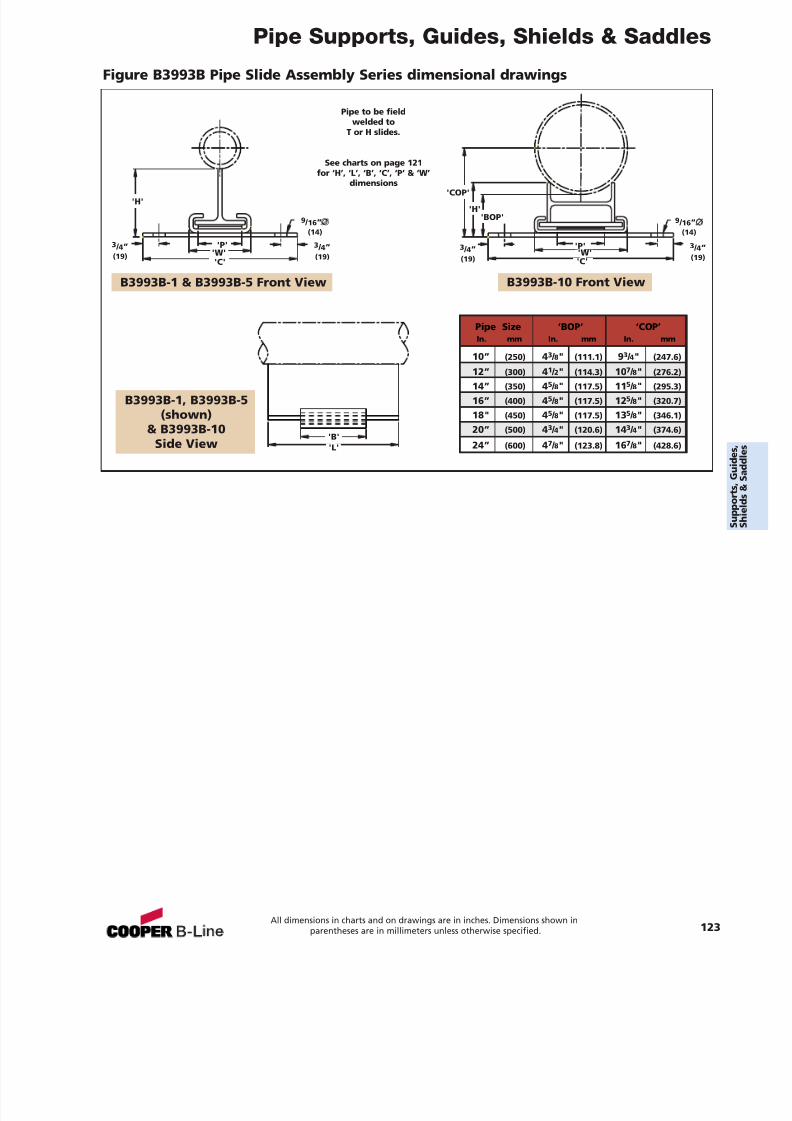
7/18/2019 PH Pipe Hanger Catalog
http://slidepdf.com/reader/full/ph-pipe-hanger-catalog 125/224
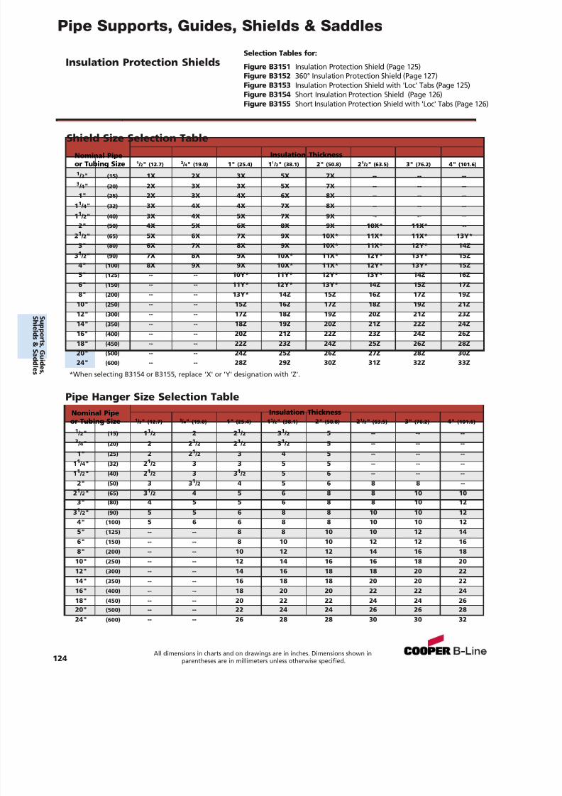
7/18/2019 PH Pipe Hanger Catalog
http://slidepdf.com/reader/full/ph-pipe-hanger-catalog 126/224
Pipe Supports, Guides, Shields & Saddles
Selection Tables for:
Figure B3151 Insulation Protection Shield (Page 125)Figure B3152 360° Insulation Protection Shield (Page 127)Figure B3153 Insulation Protection Shield with 'Loc' Tabs (Page 125)Figure B3154 Short Insulation Protection Shield (Page 126)Figure B3155 Short Insulation Protection Shield with 'Loc' Tabs (Page 126)
Insulation Protection Shields
Shield Size Selection Table
*When selecting B3154 or B3155, replace 'X' or 'Y' designation with 'Z'.
Nominal Pipe Insulation Thicknessor Tubing Size 1 / 2" (12.7) 3 / 4" (19.0) 1" (25.4) 1 1 / 2" (38.1) 2" (50.8) 2 1 / 2" (63.5) 3" (76.2) 4" (101.6)
1 / 2" (15) 1 1 / 2 2 2 1 / 2 3 1 / 2 5 -- -- --3 / 4" (20) 2 2 1 / 2 2 1 / 2 3 1 / 2 5 -- -- --1" (25) 2 2 1 / 2 3 4 5 -- -- --
11 / 4" (32) 2 1 / 2 3 3 5 5 -- -- --11 / 2" (40) 2 1 / 2 3 3 1 / 2 5 6 -- -- --
2" (50) 3 3 1 / 2 4 5 6 8 8 --21 / 2" (65) 3 1 / 2 4 5 6 8 8 10 10
3" (80) 4 5 5 6 8 8 10 1231 / 2" (90) 5 5 6 8 8 10 10 12
4" (100) 5 6 6 8 8 10 10 125" (125) -- -- 8 8 10 10 12 146" (150) -- -- 8 10 10 12 12 168" (200) -- -- 10 12 12 14 16 18
10" (250) -- -- 12 14 16 16 18 2012" (300) -- -- 14 16 18 18 20 2214" (350) -- -- 16 18 18 20 20 2216" (400) -- -- 18 20 20 22 22 2418" (450) -- -- 20 22 22 24 24 2620" (500) -- -- 22 24 24 26 26 2824" (600) -- -- 26 28 28 30 30 32
Nominal Pipe Insulation Thicknessor Tubing Size 1 / 2" (12.7) 3 / 4" (19.0) 1" (25.4) 1 1 / 2" (38.1) 2" (50.8) 2 1 / 2" (63.5) 3" (76.2) 4" (101.6)
1 / 2" (15) 1X 2X 3X 5X 7X -- -- --3 / 4" (20) 2X 3X 3X 5X 7X -- -- --1" (25) 2X 3X 4X 6X 8X -- -- --
1 1 / 4" (32) 3X 4X 4X 7X 8X -- -- --1 1 / 2" (40) 3X 4X 5X 7X 9X -- -- --
2" (50) 4X 5X 6X 8X 9X 10X* 11X* --2 1 / 2" (65) 5X 6X 7X 9X 10X* 11X* 11X* 13Y*
3" (80) 6X 7X 8X 9X 10X* 11X* 12Y* 14Z3 1 / 2" (90) 7X 8X 9X 10X* 11X* 12Y* 13Y* 15Z
4" (100) 8X 9X 9X 10X* 11X* 12Y* 13Y* 15Z5" (125) -- -- 10Y* 11Y* 12Y* 13Y* 14Z 16Z6" (150) -- -- 11Y* 12Y* 13Y* 14Z 15Z 17Z8" (200) -- -- 13Y* 14Z 15Z 16Z 17Z 19Z
10" (250) -- -- 15Z 16Z 17Z 18Z 19Z 21Z12" (300) -- -- 17Z 18Z 19Z 20Z 21Z 23Z14" (350) -- -- 18Z 19Z 20Z 21Z 22Z 24Z16" (400) -- -- 20Z 21Z 22Z 23Z 24Z 26Z18" (450) -- -- 22Z 23Z 24Z 25Z 26Z 28Z20" (500) -- -- 24Z 25Z 26Z 27Z 28Z 30Z24" (600) -- -- 28Z 29Z 30Z 31Z 32Z 33Z
Pipe Hanger Size Selection Table
124All dimensions in charts and on drawings are in inches. Dimensions shown in
parentheses are in millimeters unless otherwise specified.
S uppor t s ,Gui d es ,
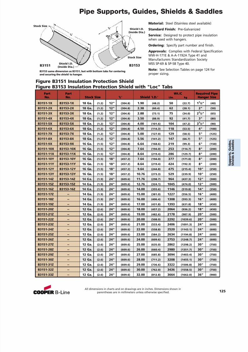
7/18/2019 PH Pipe Hanger Catalog
http://slidepdf.com/reader/full/ph-pipe-hanger-catalog 127/224
Pipe Supports, Guides, Shields & Saddles
Material: Steel (Stainless steel available)
Standard Finish: Pre-Galvanized
Service: Designed to protect pipe insulationwhen used with hangers.
Ordering: Specify part number and finish.
Approvals: Complies with Federal SpecificationWW-H-171E & A-A-1192A Type 41 andManufacturers Standardization SocietyMSS SP-69 & SP-58 Type 40.
Note: See Selection Tables on page 124 forproper sizing.
Figure B3151 Insulation Protection ShieldFigure B3153 Insulation Protection Shield with "Loc" Tabs
B3153 same dimension as B3151, but with bottom tabs for centeringand securing the shield to hanger.
'L'
'L'
B3151 B3153Shield I.D.(Inside Dia.)
Shield I.D.(Inside Dia.)
Stock Size
Stock Size
Part Part Wt./C Required PipeNo. No. Stock Size 'L' Shield 'I.D.' Lbs. kg Hanger Size
B3151-1X B3153-1X 18 Ga. (1.2) 12" (304.8) 1.90 (48.2) 50 (22.7) 1 1 / 2" (40)
B3151-2X B3153-2X 18 Ga. (1.2) 12" (304.8) 2.38 (60.4) 62 (28.1) 2" (50)
B3151-3X B3153-3X 18 Ga. (1.2) 12" (304.8) 2.88 (73.1) 75 (34.0) 2 1 / 2" (65)
B3151-4X B3153-4X 18 Ga. (1.2) 12" (304.8) 3.50 (88.9) 92 (41.7) 3" (80)
B3151-5X B3153-5X 18 Ga. (1.2) 12" (304.8) 4.00 (101.6) 104 (47.2) 3 1 / 2" (90)
B3151-6X B3153-6X 18 Ga. (1.2) 12" (304.8) 4.50 (114.3) 118 (53.5) 4" (100)
B3151-7X B3153-7X 18 Ga. (1.2) 12" (304.8) 5.00 (127.0) 129 (58.5) 5" (125)
B3151-8X B3153-8X 18 Ga. (1.2) 12" (304.8) 5.56 (141.2) 147 (66.7) 5" (125)
B3151-9X B3153-9X 16 Ga. (1.5) 12" (304.8) 6.64 (168.6) 219 (99.3) 6" (150)
B3151-10X B3153-10X 16 Ga. (1.5) 12" (304.8) 7.64 (194.0) 253 (114.7) 8" (200)
B3151-11X B3153-11X 16 Ga. (1.5) 12" (304.8) 8.64 (219.4) 286 (129.7) 8" (200)
B3151-10Y B3153-10Y 16 Ga. (1.5) 18" (457.2) 7.64 (194.0) 377 (171.0) 8" (200)
B3151-11Y B3153-11Y 16 Ga. (1.5) 18" (457.2) 8.64 (219.4) 424 (192.3) 8" (200)
B3151-12Y B3153-12Y 16 Ga. (1.5) 18" (457.2) 9.64 (244.8) 475 (215.4) 10" (250)
B3151-13Y B3153-13Y 16 Ga. (1.5) 18" (457.2) 10.76 (273.3) 529 (239.9) 10" (250)B3151-14Z B3153-14Z 14 Ga. (1.9) 24" (609.6) 11.76 (298.7) 964 (437.3) 12" (300)
B3151-15Z B3153-15Z 14 Ga. (1.9) 24" (609.6) 12.76 (324.1) 1045 (474.0) 12" (300)
B3151-16Z B3153-16Z 14 Ga. (1.9) 24" (609.6) 14.00 (355.6) 1146 (519.8) 14" (350)
B3151-17Z -- 14 Ga. (1.9) 24" (609.6) 15.00 (381.0) 1227 (556.5) 16" (400)
B3151-18Z -- 14 Ga. (1.9) 24" (609.6) 16.00 (406.4) 1308 (593.3) 16" (400)
B3151-19Z -- 14 Ga. (1.9) 24" (609.6) 17.00 (431.8) 1393 (631.8) 18" (450)
B3151-20Z -- 12 Ga. (2.6) 24" (609.6) 18.00 (457.2) 2064 (936.2) 18" (450)
B3151-21Z -- 12 Ga. (2.6) 24" (609.6) 19.00 (482.6) 2178 (987.9) 20" (500)
B3151-22Z -- 12 Ga. (2.6) 24" (609.6) 20.00 (508.0) 2292 (1039.6) 20" (500)
B3151-23Z -- 12 Ga. (2.6) 24" (609.6) 21.00 (533.4) 2406 (1091.3) 24" (600)
B3151-24Z -- 12 Ga. (2.6) 24" (609.6) 22.00 (558.8) 2520 (1143.1) 24" (600)
B3151-25Z -- 12 Ga. (2.6) 24" (609.6) 23.00 (584.2) 2634 (1194.8) 24" (600)
B3151-26Z -- 12 Ga. (2.6) 24" (609.6) 24.00 (609.6) 2753 (1248.7) 24" (600)
B3151-27Z -- 12 Ga. (2.6) 24" (609.6) 25.00 (635.0) 2862 (1298.2) 30" (750)
B3151-28Z -- 12 Ga. (2.6) 24" (609.6) 26.00 (660.4) 2980 (1351.7) 30" (750)
B3151-29Z -- 12 Ga. (2.6) 24" (609.6) 27.00 (685.8) 3094 (1403.4) 30" (750)
B3151-30Z -- 12 Ga. (2.6) 24" (609.6) 28.00 (711.2) 3208 (1455.1) 30" (750)
B3151-31Z -- 12 Ga. (2.6) 24" (609.6) 29.00 (736.6) 3322 (1506.8) 30" (750)
B3151-32Z -- 12 Ga. (2.6) 24" (609.6) 30.00 (762.0) 3436 (1558.5) 30" (750)
B3151-33Z -- 12 Ga. (2.6) 24" (609.6) 32.00 (812.8) 3664 (1662.0) 36” (900)
All dimensions in charts and on drawings are in inches. Dimensions shown inparentheses are in millimeters unless otherwise specified. 125
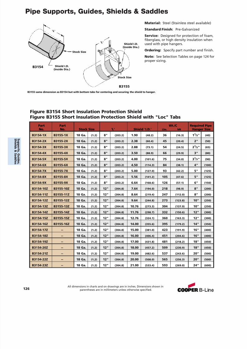
7/18/2019 PH Pipe Hanger Catalog
http://slidepdf.com/reader/full/ph-pipe-hanger-catalog 128/224
Pipe Supports, Guides, Shields & Saddles
Material: Steel (Stainless steel available)
Standard Finish: Pre-Galvanized
Service: Designed for protection of foam,fiberglass, or high density insulation whenused with pipe hangers.
Ordering: Specify part number and finish.
Note: See Selection Tables on page 124 forproper sizing.
Figure B3154 Short Insulation Protection ShieldFigure B3155 Short Insulation Protection Shield with "Loc" Tabs
B3155 same dimension as B3154 but with bottom tabs for centering and securing the shield to hanger.
Part Part Wt./C Required PipeNo. No. Stock Size 'L' Shield 'I.D.' Lbs. kN Hanger Size
B3154-1X B3155-1X 18 Ga. (1.2) 8" (203.2) 1.90 (48.2) 36 (16.3) 1 1 / 2" (40)
B3154-2X B3155-2X 18 Ga. (1.2) 8" (203.2) 2.38 (60.4) 45 (20.4) 2" (50)
B3154-3X B3155-3X 18 Ga. (1.2) 8" (203.2) 2.88 (73.1) 54 (24.5) 2 1 / 2" (65)
B3154-4X B3155-4X 18 Ga. (1.2) 8" (203.2) 3.50 (88.9) 66 (29.9) 3" (80)
B3154-5X B3155-5X 18 Ga. (1.2) 8" (203.2) 4.00 (101.6) 75 (34.0) 3 1 / 2" (90)
B3154-6X B3155-6X 18 Ga. (1.2) 8" (203.2) 4.50 (114.3) 84 (38.1) 4" (100)
B3154-7X B3155-7X 18 Ga. (1.2) 8" (203.2) 5.00 (127.0) 93 (42.2) 5" (125)
B3154-8X B3155-8X 18 Ga. (1.2) 8" (203.2) 5.56 (141.2) 105 (47.6) 5" (125)
B3154-9X B3155-9X 18 Ga. (1.2) 8" (203.2) 6.64 (168.6) 126 (57.1) 6" (150)
B3154-10Z B3155-10Z 18 Ga. (1.2) 12" (304.8) 7.64 (194.0) 218 (98.9) 8" (200)
B3154-11Z B3155-11Z 18 Ga. (1.2) 12" (304.8) 8.64 (219.4) 247 (112.0) 8" (200)
B3154-12Z B3155-12Z 18 Ga. (1.2) 12" (304.8) 9.64 (244.8) 273 (123.8) 10" (250)
B3154-13Z B3155-13Z 18 Ga. (1.2) 12" (304.8) 10.76 (273.3) 304 (137.9) 10" (250)
B3154-14Z B3155-14Z 18 Ga. (1.2) 12" (304.8) 11.76 (298.7) 332 (150.6) 12" (300)
B3154-15Z B3155-15Z 18 Ga. (1.2) 12" (304.8) 12.76 (324.1) 360 (163.3) 12" (300)
B3154-16Z B3155-16Z 18 Ga. (1.2) 12" (304.8) 14.00 (355.6) 395 (179.2) 14" (350)
B3154-17Z -- 18 Ga. (1.2) 12" (304.8) 15.00 (381.0) 423 (191.9) 16" (400)B3154-18Z -- 18 Ga. (1.2) 12" (304.8) 16.00 (406.4) 451 (204.6) 16" (400)
B3154-19Z -- 18 Ga. (1.2) 12" (304.8) 17.00 (431.8) 481 (218.2) 18" (450)
B3154-20Z -- 18 Ga. (1.2) 12" (304.8) 18.00 (457.2) 509 (230.9) 18" (450)
B3154-21Z -- 18 Ga. (1.2) 12" (304.8) 19.00 (482.6) 537 (243.6) 20" (500)
B3154-22Z -- 18 Ga. (1.2) 12" (304.8) 20.00 (508.0) 565 (256.3) 20" (500)
B3154-23Z -- 18 Ga. (1.2) 12" (304.8) 21.00 (533.4) 593 (269.0) 24" (600)
'L'
'L'
B3154
B3155
Shield I.D.(Inside Dia.)
Shield I.D.(Inside Dia.)
Stock Size
Stock Size
126All dimensions in charts and on drawings are in inches. Dimensions shown in
parentheses are in millimeters unless otherwise specified.
S uppor t s ,Gui d es ,
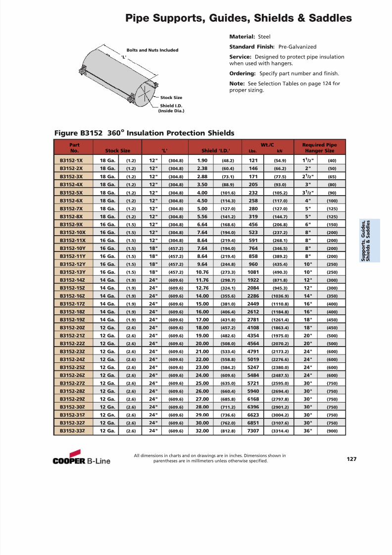
7/18/2019 PH Pipe Hanger Catalog
http://slidepdf.com/reader/full/ph-pipe-hanger-catalog 129/224
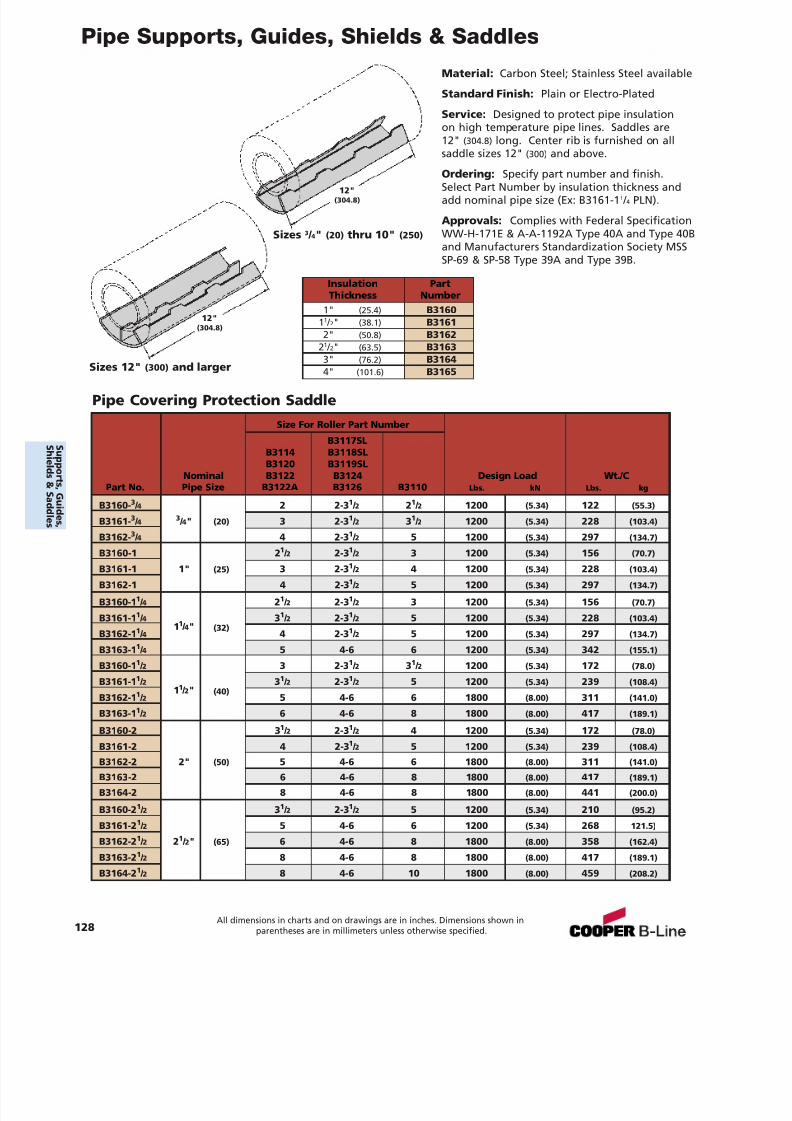
7/18/2019 PH Pipe Hanger Catalog
http://slidepdf.com/reader/full/ph-pipe-hanger-catalog 130/224
Pipe Supports, Guides, Shields & Saddles
Pipe Covering Protection Saddle
Material: Carbon Steel; Stainless Steel available
Standard Finish: Plain or Electro-Plated
Service: Designed to protect pipe insulationon high temperature pipe lines. Saddles are12" (304.8) long. Center rib is furnished on allsaddle sizes 12" (300) and above.
Ordering: Specify part number and finish.Select Part Number by insulation thickness andadd nominal pipe size (Ex: B3161-1 1 / 4 PLN).
Approvals: Complies with Federal SpecificationWW-H-171E & A-A-1192A Type 40A and Type 40Band Manufacturers Standardization Society MSSSP-69 & SP-58 Type 39A and Type 39B.
Sizes 3 / 4" (20) thru 10" (250)
Sizes 12" (300) and larger
12"(304.8)
12"(304.8)
Size For Roller Part Number
B3117SLB3114 B3118SLB3120 B3119SL
Nominal B3122 B3124 Design Load Wt./CPart No. Pipe Size B3122A B3126 B3110 Lbs. kN Lbs. kg
B3160- 3 / 4 2 2-3 1 / 2 21 / 2 1200 (5.34) 122 (55.3)
B3161- 3 / 4 3 / 4" (20) 3 2-3 1 / 2 31 / 2 1200 (5.34) 228 (103.4)
B3162- 3 / 4 4 2-3 1 / 2 5 1200 (5.34) 297 (134.7)
B3160-1 21
/ 2 2-31
/ 2 3 1200 (5.34) 156 (70.7)B3161-1 1" (25) 3 2-3 1 / 2 4 1200 (5.34) 228 (103.4)
B3162-1 4 2-3 1 / 2 5 1200 (5.34) 297 (134.7)
B3160-1 1 / 4 21 / 2 2-3 1 / 2 3 1200 (5.34) 156 (70.7)
B3161-1 1 / 4 31 / 2 2-3 1 / 2 5 1200 (5.34) 228 (103.4)
B3162-1 1 / 411 / 4" (32)
4 2-3 1 / 2 5 1200 (5.34) 297 (134.7)
B3163-1 1 / 4 5 4-6 6 1200 (5.34) 342 (155.1)
B3160-1 1 / 2 3 2-3 1 / 2 31 / 2 1200 (5.34) 172 (78.0)
B3161-1 1 / 2 31 / 2 2-3 1 / 2 5 1200 (5.34) 239 (108.4)
B3162-1 1 / 211 / 2" (40)
5 4-6 6 1800 (8.00) 311 (141.0)
B3163-1 1 / 2 6 4-6 8 1800 (8.00) 417 (189.1)
B3160-2 3 1 / 2 2-3 1 / 2 4 1200 (5.34) 172 (78.0)
B3161-2 4 2-3 1 / 2 5 1200 (5.34) 239 (108.4)
B3162-2 2" (50) 5 4-6 6 1800 (8.00) 311 (141.0)
B3163-2 6 4-6 8 1800 (8.00) 417 (189.1)
B3164-2 8 4-6 8 1800 (8.00) 441 (200.0)
B3160-2 1 / 2 31 / 2 2-3 1 / 2 5 1200 (5.34) 210 (95.2)
B3161-2 1 / 2 5 4-6 6 1200 (5.34) 268 121.5)
B3162-2 1 / 2 21 / 2" (65) 6 4-6 8 1800 (8.00) 358 (162.4)
B3163-2 1 / 2 8 4-6 8 1800 (8.00) 417 (189.1)
B3164-2 1 / 2 8 4-6 10 1800 (8.00) 459 (208.2)
128All dimensions in charts and on drawings are in inches. Dimensions shown in
parentheses are in millimeters unless otherwise specified.
Insulation PartThickness Number
1" (25.4) B316011 / 2" (38.1) B31612" (50.8) B3162
21 / 2" (63.5) B31633" (76.2) B3164
4" (101.6) B3165
S uppor t s ,Gui d es ,
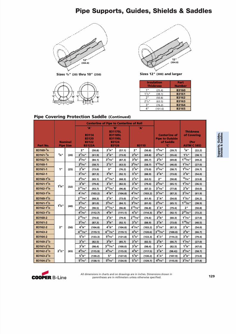
7/18/2019 PH Pipe Hanger Catalog
http://slidepdf.com/reader/full/ph-pipe-hanger-catalog 131/224
Pipe Supports, Guides, Shields & Saddles
Pipe Covering Protection Saddle (Continued)
Insulation PartThickness Number
1" (25.4) B316011 / 2" (38.1) B31612" (50.8) B3162
21 / 2" (63.5) B31633" (76.2) B31644" (101.6) B3165
Sizes 3 / 4" (20) thru 10" (250) Sizes 12" (300) and larger
12"(304.8)
'C''C' 'A' 'B'
12"(304.8)
Centerline of Pipe to Centerline of Roll
'A' 'B' 'A'B3117SL Thickness
B3114 B3118SL Centerline of of CoveringB3120 B3119SL Pipe to Outside
Nominal B3122 B3124 of Saddle (PerPart No. Pipe Size B3122A B3126 B3110 'C' ASTM C 585)
B3160- 3 / 4 2" (50.8) 21 / 4" (57.1) 2" (50.8) 19 / 16 " (39.7) 7 / 8" (22.2)
B3161- 3 / 4 3 / 4" (20) 27 / 16 " (61.9) 27 / 8" (73.0) 23 / 4" (69.8) 23 / 16 " (55.6) 1 1 / 2" (38.1)
B3162- 3 / 4 35 / 16 " (84.1) 37 / 16 " (87.3) 33 / 8" (85.7) 23 / 4" (69.8) 115 / 16 " (49.2)
B3160-1 25
/ 16 " (58.7) 21
/ 2" (63.5) 25
/ 16 " (58.7) 113
/ 16 " (46.0) 11
/ 16 " (27.0)B3161-1 1" (25) 27 / 8" (73.0) 3" (76.2) 27 / 8" (73.0) 25 / 16 " (58.7) 19 / 16 " (39.7)
B3162-1 3 7 / 16 " (87.3) 35 / 8" (92.1) 31 / 2" (88.9) 27 / 8" (73.0) 21 / 8" (54.0)
B3160-1 1 / 4 29 / 16 " (65.1) 211 / 16 " (68.3) 21 / 2" (63.5) 2" (50.8) 15 / 16 " (23.8)
B3161-1 1 / 4 31 / 8" (79.4) 31 / 4" (82.5) 31 / 8" (79.4) 29 / 16 " (65.1) 17 / 16 " (36.5)
B3162-1 1 / 411 / 4" (32)
311 / 16 " (93.7) 313 / 16 " (96.8) 37 / 16 " (87.3) 31 / 16 " (77.8) 21 / 8" (54.0)
B3163-1 1 / 4 41 / 16 " (103.2) 41 / 8" (104.8) 41 / 16 " (103.2) 37 / 16 " (87.3) 27 / 16 " (61.9)
B3160-1 1 / 2 211 / 16 " (68.3) 27 / 8" (73.0) 27 / 16 " (61.9) 21 / 8" (54.0) 11 / 32 " (26.2)
B3161-1 1 / 2 33 / 16 " (81.0) 35 / 16 " (84.1) 33 / 16 " (81.0) 29 / 16 " (65.1) 117 / 32 " (38.9)
B3162-1 1 / 211 / 2" (40)
39 / 16 " (90.5) 313 / 16 " (96.8) 313 / 16 " (96.8) 31 / 8" (79.4) 2" (50.8)
B3163-1 1 / 2 47 / 16 " (112.7) 43 / 8" (111.1) 41 / 2" (114.3) 35 / 8" (92.1) 227 / 32 " (72.2)
B3160-2 2 15 / 16 " (74.6) 31 / 8" (79.4) 215 / 16 " (74.6) 23 / 8" (60.3) 11 / 16 " (27.0)
B3161-2 3 7 / 16 " (87.3) 35 / 8" (92.1) 31 / 2" (88.9) 27 / 8" (73.0) 119 / 32 " (40.5)
B3162-2 2" (50) 41 / 8" (104.8) 41 / 8" (104.8) 41 / 16 " (103.2) 37 / 16 " (87.3) 21 / 8" (54.0)
B3163-2 4 11 / 16 " (119.1) 411 / 16 " (119.1) 43 / 4" (120.6) 315 / 16 " (100.0) 25 / 8" (66.7)
B3164-2 5 1 / 4" (133.3) 53 / 16 " (131.8) 51 / 4" (133.3) 41 / 2" (114.3) 31 / 8" (79.4)
B3160-2 1 / 2 31 / 4" (82.5) 33 / 8" (85.7) 31 / 4" (82.5) 25 / 8" (66.7) 11 / 16 " (27.0)
B3161-2 1 / 2 37 / 8" (98.4) 315 / 16 " (100.0) 37 / 8" (98.4) 31 / 4" (82.5) 17 / 8" (47.6)
B3162-2 1 / 2 21 / 2" (65) 49 / 16 " (115.9) 49 / 16 " (115.9) 45 / 8" (117.5) 37 / 8" (98.4)) 25 / 16 " (58.7)
B3163-2 1 / 2 51 / 8" (130.2) 5" (127.0) 51 / 8" (130.2) 41 / 4" (107.9) 27 / 8" (73.0)
B3164-2 1 / 2 57 / 16 " (138.1) 55 / 16 " (134.9) 51 / 2" (139.7) 49 / 16 " (115.9) 31 / 16 " (77.8)
All dimensions in charts and on drawings are in inches. Dimensions shown inparentheses are in millimeters unless otherwise specified. 129
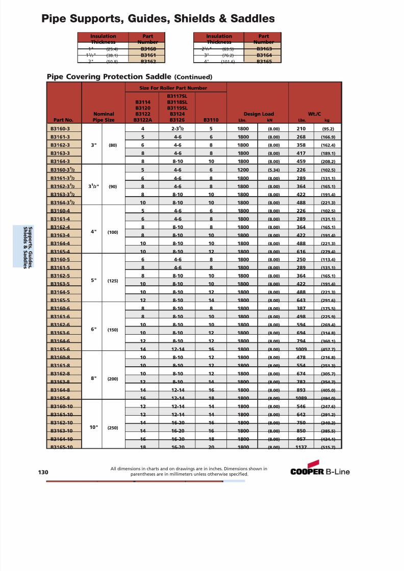
7/18/2019 PH Pipe Hanger Catalog
http://slidepdf.com/reader/full/ph-pipe-hanger-catalog 132/224
Pipe Supports, Guides, Shields & Saddles
Pipe Covering Protection Saddle (Continued)
Size For Roller Part Number
B3117SLB3114 B3118SLB3120 B3119SL
Nominal B3122 B3124 Design Load Wt./CPart No. Pipe Size B3122A B3126 B3110 Lbs. kN Lbs. kg
B3160-3 4 2-3 1 / 2 5 1800 (8.00) 210 (95.2)
B3161-3 5 4-6 6 1800 (8.00) 268 (166.9)
B3162-3 3" (80) 6 4-6 8 1800 (8.00) 358 (162.4)
B3163-3 8 4-6 8 1800 (8.00) 417 (189.1)
B3164-3 8 8-10 10 1800 (8.00) 459 (208.2)
B3160-3 1 / 2 5 4-6 6 1200 (5.34) 226 (102.5)
B3161-3 1 / 2 6 4-6 8 1800 (8.00) 289 (131.1)
B3162-31
/ 2
31
/ 2" (90) 8 4-6 8 1800 (8.00) 364 (165.1)
B3163-3 1 / 2 8 8-10 10 1800 (8.00) 422 (191.4)
B3164-3 1 / 2 10 8-10 10 1800 (8.00) 488 (221.3)
B3160-4 5 4-6 6 1800 (8.00) 226 (102.5)
B3161-4 6 4-6 8 1800 (8.00) 289 (131.1)
B3162-4 8 8-10 8 1800 (8.00) 364 (165.1)
B3163-44" (100)
8 8-10 10 1800 (8.00) 422 (191.4)
B3164-4 10 8-10 10 1800 (8.00) 488 (221.3)
B3165-4 10 8-10 12 1800 (8.00) 616 (279.4)
B3160-5 6 4-6 8 1800 (8.00) 250 (113.4)
B3161-5 8 4-6 8 1800 (8.00) 289 (131.1)
B3162-5 8 8-10 10 1800 (8.00) 364 (165.1)
B3163-55" (125)
10 8-10 10 1800 (8.00) 422 (191.4)
B3164-5 10 8-10 12 1800 (8.00) 488 (221.3)
B3165-5 12 8-10 14 1800 (8.00) 643 (291.6)
B3160-6 8 8-10 8 1800 (8.00) 387 (175.5)
B3161-6 8 8-10 10 1800 (8.00) 498 (225.9)
B3162-6 10 8-10 10 1800 (8.00) 594 (269.4)
B3163-66" (150)
10 8-10 12 1800 (8.00) 694 (314.8)
B3164-6 12 8-10 12 1800 (8.00) 794 (360.1)
B3165-6 14 12-14 16 1800 (8.00) 1009 (457.7)
B3160-8 10 8-10 12 1800 (8.00) 478 (216.8)
B3161-8 10 8-10 12 1800 (8.00) 554 (251.3)
B3162-8 10 8-10 12 1800 (8.00) 674 (305.7)
B3163-8 8" (200) 12 8-10 14 1800 (8.00) 782 (354.7)
B3164-8 14 12-14 16 1800 (8.00) 893 (405.0)
B3165-8 16 12-14 18 1800 (8.00) 1089 (494.0)
B3160-10 12 12-14 14 1800 (8.00) 546 (247.6)
B3161-10 12 12-14 14 1800 (8.00) 642 (291.2)
B3162-10 14 16-20 16 1800 (8.00) 750 (340.2)
B3163-1010" (250)
14 16-20 16 1800 (8.00) 850 (385.5)
B3164-10 16 16-20 18 1800 (8.00) 957 (434.1)
B3165-10 18 16-20 20 1800 (8.00) 1137 (515.7)
130All dimensions in charts and on drawings are in inches. Dimensions shown in
parentheses are in millimeters unless otherwise specified.
Insulation PartThickness Number
1" (25.4) B316011 / 2" (38.1) B31612" (50.8) B3162
Insulation PartThickness Number
21 / 2" (63.5) B31633" (76.2) B31644" (101.6) B3165
S uppor t s ,Gui d es ,
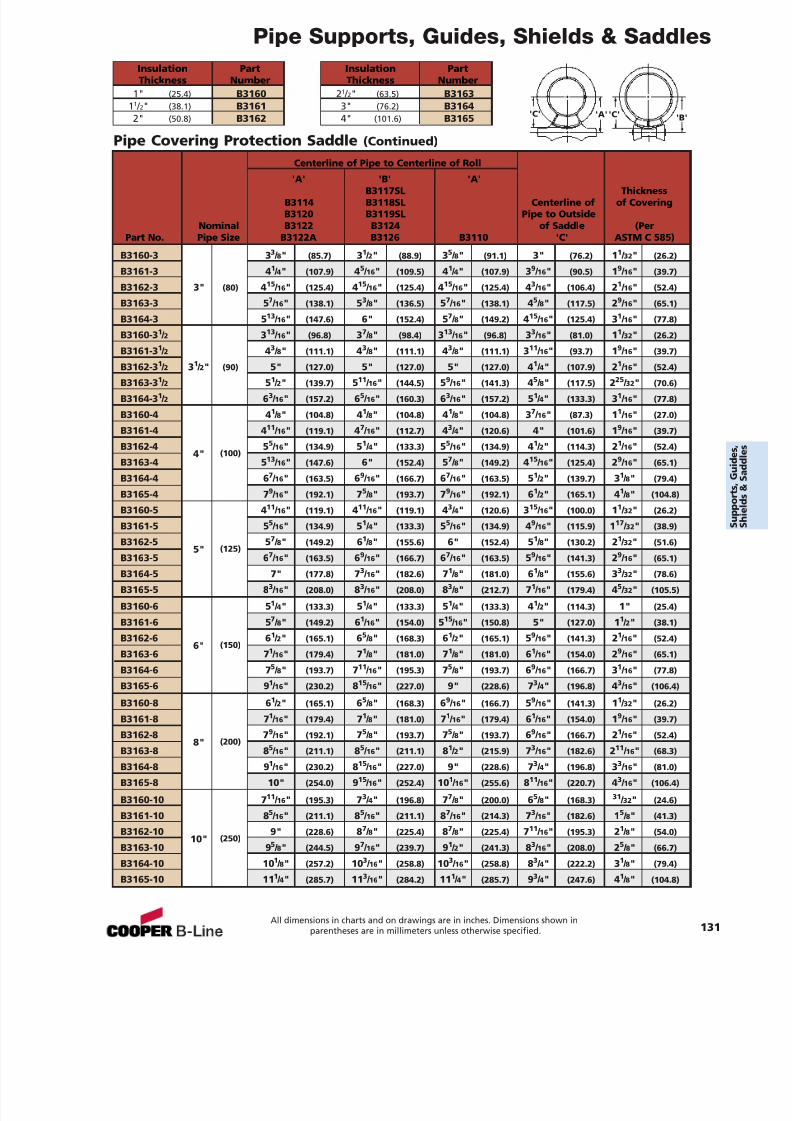
7/18/2019 PH Pipe Hanger Catalog
http://slidepdf.com/reader/full/ph-pipe-hanger-catalog 133/224
Pipe Supports, Guides, Shields & Saddles
Pipe Covering Protection Saddle (Continued)
'A' 'B''C''C'
Centerline of Pipe to Centerline of Roll
'A' 'B' 'A'B3117SL Thickness
B3114 B3118SL Centerline of of CoveringB3120 B3119SL Pipe to Outside
Nominal B3122 B3124 of Saddle (PerPart No. Pipe Size B3122A B3126 B3110 'C' ASTM C 585)
B3160-3 3 3 / 8" (85.7) 31 / 2" (88.9) 35 / 8" (91.1) 3" (76.2) 11 / 32 " (26.2)
B3161-3 4 1 / 4" (107.9) 45 / 16 " (109.5) 41 / 4" (107.9) 39 / 16 " (90.5) 19 / 16 " (39.7)
B3162-3 3" (80) 415 / 16 " (125.4) 415 / 16 " (125.4) 415 / 16 " (125.4) 43 / 16 " (106.4) 21 / 16 " (52.4)
B3163-3 5 7 / 16 " (138.1) 53 / 8" (136.5) 57 / 16 " (138.1) 45 / 8" (117.5) 29 / 16 " (65.1)
B3164-3 5 13 / 16 " (147.6) 6" (152.4) 57 / 8" (149.2) 415 / 16 " (125.4) 31 / 16 " (77.8)
B3160-3 1 / 2 313 / 16 " (96.8) 37 / 8" (98.4) 313 / 16 " (96.8) 33 / 16 " (81.0) 11 / 32 " (26.2)
B3161-3 1 / 2 43 / 8" (111.1) 43 / 8" (111.1) 43 / 8" (111.1) 311 / 16 " (93.7) 19 / 16 " (39.7)
B3162-31
/ 2 31
/ 2" (90) 5" (127.0) 5" (127.0) 5" (127.0) 41
/ 4" (107.9) 21
/ 16 " (52.4)B3163-3 1 / 2 51 / 2" (139.7) 511 / 16 " (144.5) 59 / 16 " (141.3) 45 / 8" (117.5) 225 / 32 " (70.6)
B3164-3 1 / 2 63 / 16 " (157.2) 65 / 16 " (160.3) 63 / 16 " (157.2) 51 / 4" (133.3) 31 / 16 " (77.8)
B3160-4 4 1 / 8" (104.8) 41 / 8" (104.8) 41 / 8" (104.8) 37 / 16 " (87.3) 11 / 16 " (27.0)
B3161-4 4 11 / 16 " (119.1) 47 / 16 " (112.7) 43 / 4" (120.6) 4" (101.6) 19 / 16 " (39.7)
B3162-44" (100)
55 / 16 " (134.9) 51 / 4" (133.3) 55 / 16 " (134.9) 41 / 2" (114.3) 21 / 16 " (52.4)
B3163-4 5 13 / 16 " (147.6) 6" (152.4) 57 / 8" (149.2) 415 / 16 " (125.4) 29 / 16 " (65.1)
B3164-4 6 7 / 16 " (163.5) 69 / 16 " (166.7) 67 / 16 " (163.5) 51 / 2" (139.7) 31 / 8" (79.4)
B3165-4 7 9 / 16 " (192.1) 75 / 8" (193.7) 79 / 16 " (192.1) 61 / 2" (165.1) 41 / 8" (104.8)
B3160-5 4 11 / 16 " (119.1) 411 / 16 " (119.1) 43 / 4" (120.6) 315 / 16 " (100.0) 11 / 32 " (26.2)
B3161-5 5 5 / 16 " (134.9) 51 / 4" (133.3) 55 / 16 " (134.9) 49 / 16 " (115.9) 117 / 32 " (38.9)
B3162-55" (125)
57 / 8" (149.2) 61 / 8" (155.6) 6" (152.4) 51 / 8" (130.2) 21 / 32 " (51.6)
B3163-5 6 7 / 16 " (163.5) 69 / 16 " (166.7) 67 / 16 " (163.5) 59 / 16 " (141.3) 29 / 16 " (65.1)
B3164-5 7" (177.8) 73 / 16 " (182.6) 71 / 8" (181.0) 61 / 8" (155.6) 33 / 32 " (78.6)
B3165-5 8 3 / 16 " (208.0) 83 / 16 " (208.0) 83 / 8" (212.7) 71 / 16 " (179.4) 45 / 32 " (105.5)
B3160-6 5 1 / 4" (133.3) 51 / 4" (133.3) 51 / 4" (133.3) 41 / 2" (114.3) 1" (25.4)
B3161-6 5 7 / 8" (149.2) 61 / 16 " (154.0) 515 / 16 " (150.8) 5" (127.0) 11 / 2" (38.1)
B3162-66" (150)
61 / 2" (165.1) 65 / 8" (168.3) 61 / 2" (165.1) 59 / 16 " (141.3) 21 / 16 " (52.4)
B3163-6 7 1 / 16 " (179.4) 71 / 8" (181.0) 71 / 8" (181.0) 61 / 16 " (154.0) 29 / 16 " (65.1)
B3164-6 7 5 / 8" (193.7) 711 / 16 " (195.3) 75 / 8" (193.7) 69 / 16 " (166.7) 31 / 16 " (77.8)
B3165-6 9 1 / 16 " (230.2) 815 / 16 " (227.0) 9" (228.6) 73 / 4" (196.8) 43 / 16 " (106.4)
B3160-8 6 1 / 2" (165.1) 65 / 8" (168.3) 69 / 16 " (166.7) 59 / 16 " (141.3) 11 / 32 " (26.2)
B3161-8 7 1 / 16 " (179.4) 71 / 8" (181.0) 71 / 16 " (179.4) 61 / 16 " (154.0) 19 / 16 " (39.7)
B3162-88" (200)
79 / 16 " (192.1) 75 / 8" (193.7) 75 / 8" (193.7) 69 / 16 " (166.7) 21 / 16 " (52.4)
B3163-8 8 5 / 16 " (211.1) 85 / 16 " (211.1) 81 / 2" (215.9) 73 / 16 " (182.6) 211 / 16 " (68.3)
B3164-8 9 1 / 16 " (230.2) 815 / 16 " (227.0) 9" (228.6) 73 / 4" (196.8) 33 / 16 " (81.0)
B3165-8 10" (254.0) 915 / 16 " (252.4) 10 1 / 16 " (255.6) 811 / 16 " (220.7) 43 / 16 " (106.4)
B3160-10 7 11 / 16 " (195.3) 73 / 4" (196.8) 77 / 8" (200.0) 65 / 8" (168.3) 31 / 32 " (24.6)
B3161-10 8 5 / 16 " (211.1) 85 / 16 " (211.1) 87 / 16 " (214.3) 73 / 16 " (182.6) 15 / 8" (41.3)
B3162-1010" (250)
9" (228.6) 87 / 8" (225.4) 87 / 8" (225.4) 711 / 16 " (195.3) 21 / 8" (54.0)
B3163-10 9 5 / 8" (244.5) 97 / 16 " (239.7) 91 / 2" (241.3) 83 / 16 " (208.0) 25 / 8" (66.7)
B3164-10 10 1 / 8" (257.2) 10 3 / 16 " (258.8) 10 3 / 16 " (258.8) 83 / 4" (222.2) 31 / 8" (79.4)
B3165-10 11 1 / 4" (285.7) 11 3 / 16 " (284.2) 11 1 / 4" (285.7) 93 / 4" (247.6) 41 / 8" (104.8)
All dimensions in charts and on drawings are in inches. Dimensions shown inparentheses are in millimeters unless otherwise specified. 131
Insulation PartThickness Number
1" (25.4) B316011 / 2" (38.1) B31612" (50.8) B3162
Insulation PartThickness Number
21 / 2" (63.5) B31633" (76.2) B31644" (101.6) B3165
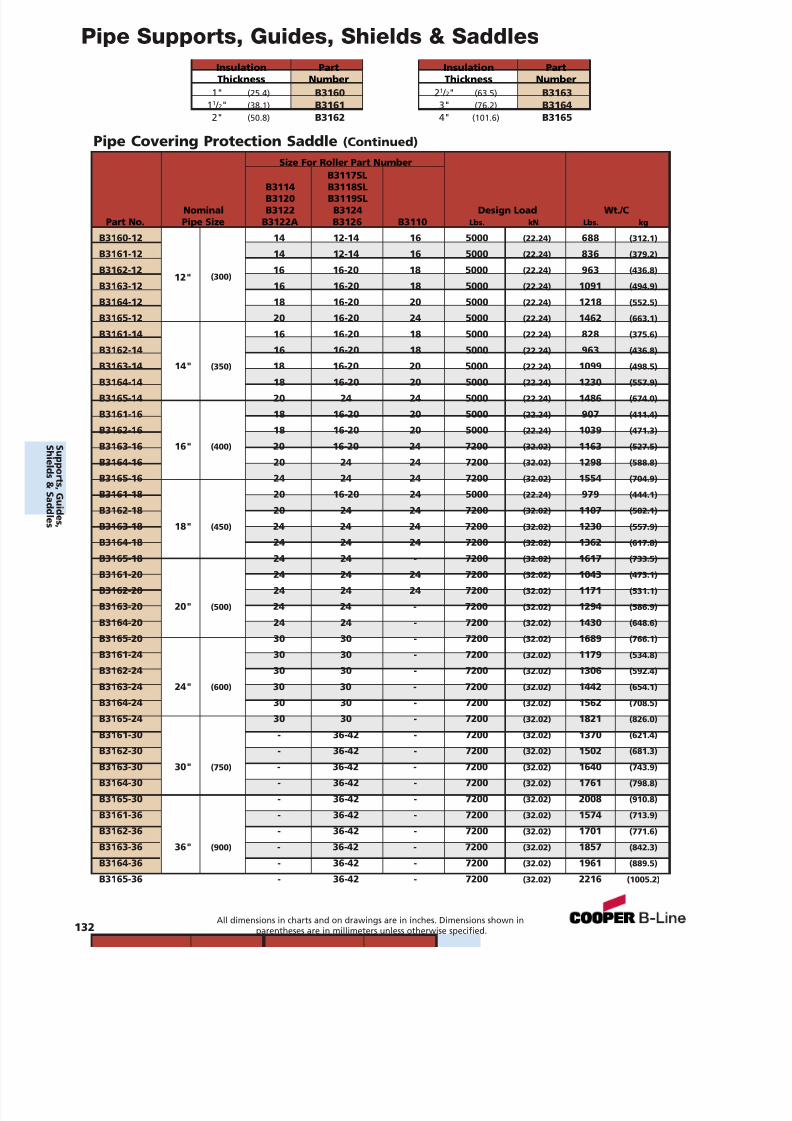
7/18/2019 PH Pipe Hanger Catalog
http://slidepdf.com/reader/full/ph-pipe-hanger-catalog 134/224
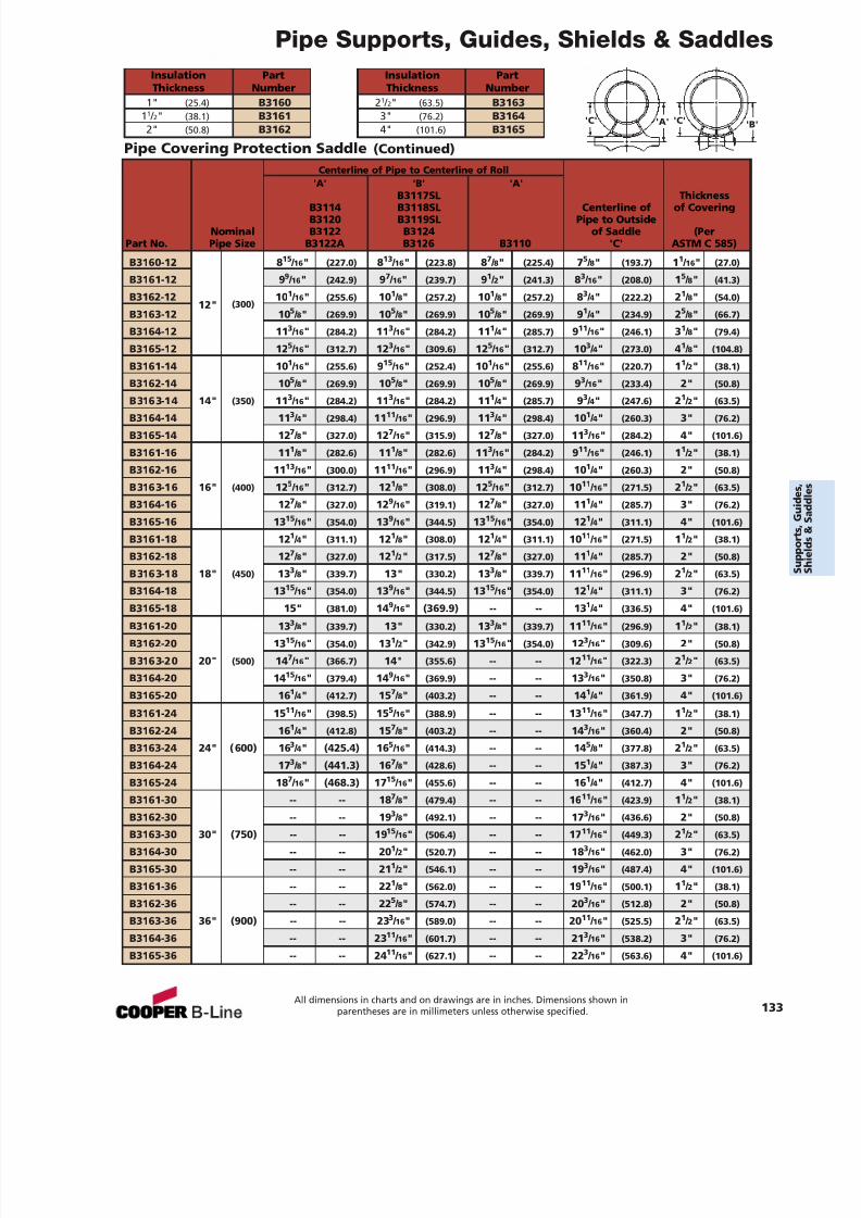
7/18/2019 PH Pipe Hanger Catalog
http://slidepdf.com/reader/full/ph-pipe-hanger-catalog 135/224
Pipe Supports, Guides, Shields & SaddlesInsulation PartThickness Number
1" (25.4) B316011 / 2" (38.1) B31612" (50.8) B3162
Insulation PartThickness Number
21 / 2" (63.5) B31633" (76.2) B31644" (101.6) B3165
Pipe Covering Protection Saddle (Continued)
'C''C' 'A' 'B'
Centerline of Pipe to Centerline of Roll'A' 'B' 'A'
B3117SL ThicknessB3114 B3118SL Centerline of of CoveringB3120 B3119SL Pipe to Outside
Nominal B3122 B3124 of Saddle (PerPart No. Pipe Size B3122A B3126 B3110 'C' ASTM C 585)
B3160-12 8 15 / 16 " (227.0) 813 / 16 " (223.8) 87 / 8" (225.4) 75 / 8" (193.7) 11 / 16 " (27.0)
B3161-12 9 9 / 16 " (242.9) 97 / 16 " (239.7) 91 / 2" (241.3) 83 / 16 " (208.0) 15 / 8" (41.3)
B3162-1212" (300)
10 1 / 16 " (255.6) 10 1 / 8" (257.2) 10 1 / 8" (257.2) 83 / 4" (222.2) 21 / 8" (54.0)
B3163-12 10 5 / 8" (269.9) 10 5 / 8" (269.9) 10 5 / 8" (269.9) 91 / 4" (234.9) 25 / 8" (66.7)
B3164-12 11 3 / 16 " (284.2) 11 3 / 16 " (284.2) 11 1 / 4" (285.7) 911 / 16 " (246.1) 31 / 8" (79.4)
B3165-12 12 5 / 16 " (312.7) 12 3 / 16 " (309.6) 12 5 / 16 " (312.7) 10 3 / 4" (273.0) 41 / 8" (104.8)
B3161-14 10 1 / 16 " (255.6) 915 / 16 " (252.4) 10 1 / 16 " (255.6) 811 / 16 " (220.7) 11 / 2" (38.1)
B3162-14 10 5 / 8" (269.9) 10 5 / 8" (269.9) 10 5 / 8" (269.9) 93 / 16 " (233.4) 2" (50.8)
B3163-14 14" (350) 113 / 16 " (284.2) 11
3 / 16 " (284.2) 11
1 / 4" (285.7) 9
3 / 4" (247.6) 2
1 / 2" (63.5)
B3164-14 11 3 / 4" (298.4) 11 11 / 16 " (296.9) 11 3 / 4" (298.4) 10 1 / 4" (260.3) 3" (76.2)
B3165-14 12 7 / 8" (327.0) 12 7 / 16 " (315.9) 12 7 / 8" (327.0) 11 3 / 16 " (284.2) 4" (101.6)
B3161-16 11 1 / 8" (282.6) 11 1 / 8" (282.6) 11 3 / 16 " (284.2) 911 / 16 " (246.1) 11 / 2" (38.1)
B3162-16 11 13 / 16 " (300.0) 11 11 / 16 " (296.9) 11 3 / 4" (298.4) 10 1 / 4" (260.3) 2" (50.8)
B3163-16 16" (400) 12 5 / 16 " (312.7) 12 1 / 8" (308.0) 12 5 / 16 " (312.7) 10 11 / 16 " (271.5) 21 / 2" (63.5)
B3164-16 12 7 / 8" (327.0) 12 9 / 16 " (319.1) 12 7 / 8" (327.0) 11 1 / 4" (285.7) 3" (76.2)
B3165-16 13 15 / 16 " (354.0) 13 9 / 16 " (344.5) 13 15 / 16 " (354.0) 12 1 / 4" (311.1) 4" (101.6)
B3161-18 12 1 / 4" (311.1) 12 1 / 8" (308.0) 12 1 / 4" (311.1) 10 11 / 16 " (271.5) 11 / 2" (38.1)
B3162-18 12 7 / 8" (327.0) 12 1 / 2" (317.5) 12 7 / 8" (327.0) 11 1 / 4" (285.7) 2" (50.8)
B3163-18 18" (450) 13 3 / 8" (339.7) 13" (330.2) 13 3 / 8" (339.7) 11 11 / 16 " (296.9) 21 / 2" (63.5)
B3164-18 13 15 / 16 " (354.0) 13 9 / 16 " (344.5) 13 15 / 16 " (354.0) 12 1 / 4" (311.1) 3" (76.2)
B3165-18 15" (381.0) 14 9 / 16 " (369.9) -- -- 13 1 / 4" (336.5) 4" (101.6)
B3161-20 13 3 / 8" (339.7) 13" (330.2) 13 3 / 8" (339.7) 11 11 / 16 " (296.9) 11 / 2" (38.1)
B3162-20 13 15 / 16 " (354.0) 13 1 / 2" (342.9) 13 15 / 16 " (354.0) 12 3 / 16 " (309.6) 2" (50.8)
B3163-20 20" (500) 14 7 / 16 " (366.7) 14" (355.6) -- -- 12 11 / 16 " (322.3) 21 / 2" (63.5)
B3164-20 14 15 / 16 " (379.4) 14 9 / 16 " (369.9) -- -- 13 3 / 16 " (350.8) 3" (76.2)
B3165-20 16 1 / 4" (412.7) 15 7 / 8" (403.2) -- -- 14 1 / 4" (361.9) 4" (101.6)
B3161-24 15 11 / 16 " (398.5) 15 5 / 16 " (388.9) -- -- 13 11 / 16 " (347.7) 11 / 2" (38.1)
B3162-24 16 1 / 4" (412.8) 15 7 / 8" (403.2) -- -- 14 3 / 16 " (360.4) 2" (50.8)
B3163-24 24" (600) 16 3 / 4" (425.4) 16 5 / 16 " (414.3) -- -- 14 5 / 8" (377.8) 21 / 2" (63.5)
B3164-24 17 3 / 8" (441.3) 16 7 / 8" (428.6) -- -- 15 1 / 4" (387.3) 3" (76.2)
B3165-24 18 7 / 16 " (468.3) 17 15 / 16 " (455.6) -- -- 16 1 / 4" (412.7) 4" (101.6)
B3161-30 -- -- 18 7 / 8" (479.4) -- -- 16 11 / 16 " (423.9) 11 / 2" (38.1)
B3162-30 -- -- 19 3 / 8" (492.1) -- -- 17 3 / 16 " (436.6) 2" (50.8)
B3163-30 30" (750) -- -- 19 15 / 16 " (506.4) -- -- 17 11 / 16 " (449.3) 21 / 2" (63.5)
B3164-30 -- -- 20 1 / 2" (520.7) -- -- 18 3 / 16 " (462.0) 3" (76.2)
B3165-30 -- -- 21 1 / 2" (546.1) -- -- 19 3 / 16 " (487.4) 4" (101.6)
B3161-36 -- -- 22 1 / 8" (562.0) -- -- 19 11 / 16 " (500.1) 11 / 2" (38.1)
B3162-36 -- -- 22 5 / 8" (574.7) -- -- 20 3 / 16 " (512.8) 2" (50.8)
B3163-36 36" (900) -- -- 23 3 / 16 " (589.0) -- -- 20 11 / 16 " (525.5) 21 / 2" (63.5)
B3164-36 -- -- 23 11 / 16 " (601.7) -- -- 21 3 / 16 " (538.2) 3" (76.2)
B3165-36 -- -- 24 11 / 16 " (627.1) -- -- 22 3 / 16 " (563.6) 4" (101.6)
All dimensions in charts and on drawings are in inches. Dimensions shown inparentheses are in millimeters unless otherwise specified. 133

7/18/2019 PH Pipe Hanger Catalog
http://slidepdf.com/reader/full/ph-pipe-hanger-catalog 136/224
Concrete inserts of fered in this sec tion are d esigned to provide a pre -set support point in con creteceilin gs, walls , and floor s. A range of insert s with varying design loads are available.
MaterialsCarbon Steel and Malleable Iron are used in the manufacture of concrete insert s. Stainles s Steel an dother materials are available.
FinishesThe stan d ard finishes for mechanical supports are plain steel (oil coated) sometim es referre d to as blackan d Electro -Plate d Zinc (ASTM B 633 SC3). Hot-Dip Galvanized Af ter Fabrication (ASTM A 123), Re d Primer,Plastic Coating, Dura-Gre en ® and oth er spe cial coatings are available up on re quest.
Approvals (as note d)Items in this section are Und erwriter s’ L ab oratories Listed, comply with F ederal Sp ecific ation W W-H -171E& A-A-1192A or Manufacturer s St andardization So ciet y MSS SP-69 & SP-5 8.
134
Concrete Inserts
C onc r et eI ns er t s
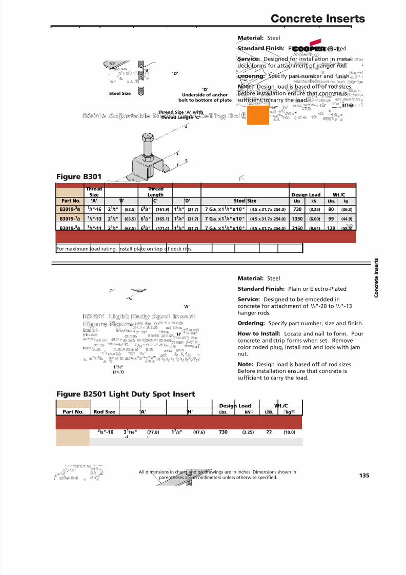
7/18/2019 PH Pipe Hanger Catalog
http://slidepdf.com/reader/full/ph-pipe-hanger-catalog 137/224
Concrete Inserts
Material: Steel
Stan dard Finish: Plain or Electro-Plated
Service: Designed for installation in metaldeck forms for attachment of hanger rod.
Ordering: Specify part number and finish.
Note: Design load is based off of rod sizes.
Before installation ensure that concrete issufficient to carry the load.
Figure B3019 Adjustable Metal Deck Ceiling Bolt
Material: Steel
Stan dard Finish: Plain or Electro-Plated
Service: Designed to be embedded inconcrete for attachment of 1 / 4"-20 to 1 / 2"-13hanger rods.
Ordering: Specify part number, size and finish.
How to In st all: Locate and nail to form. Pourconcrete and strip forms when set. Removecolor coded plug, install rod and lock with jamnut.
Note: Design load is based off of rod sizes.Before installation ensure that concrete is
sufficient to carry the load.
Figure B2501 Light Duty Spot Insert
'D'
Und er side of anchorbolt to bot tom of pl ate
Thre ad Size 'A' withThre ad Len g th 'C'
Steel Size
'B''D'
'H'
1 1 / 4"(31.7)
'A'
For maximum load rating, install plate on top of deck ribs.
Thre ad Thr ea dSize Length D esign Lo ad W t./CPar t N o. 'A' 'B' 'C' 'D' St eel Siz e Lbs kN Lbs. kg
B3019 -3 / 8 3 / 8"-16 2 1 / 2" (63.5) 63 / 8" (161.9) 11 / 4" (31.7) 7 Ga. x1 1 / 4"x10" (4.5 x 31.7x 254.0) 730 (3.25) 80 (36.3)
B3019 -1 / 2 1 / 2"-13 2 1 / 2" (63.5) 61 / 2" (165.1) 11 / 4" (31.7) 7 Ga. x1 1 / 4"x10" (4.5 x 31.7x 254.0) 1350 (6.00) 99 (44.9)
B3019 -5 / 8 5 / 8"-11 2 1 / 2" (63.5) 63 / 4" (171.4) 11 / 4" (31.7) 7 Ga. x1 1 / 4"x10" (4.5 x 31.7x 254.0) 2160 (9.61) 129 (58.5)
B3019 -3 / 4 3 / 4"-10 2 1 / 2" (63.5) 63 / 16" (157.2) 21 / 4" (57.1) 1 / 4" x 3" x 10" (6.3 x76. 2 x 254.0) 3230 (14.37) 238 (107.9)
Design Lo ad W t./ CPar t No. Ro d Size 'A' 'H' Lbs. kN Lb s. kg
B2501- 1 / 4 1 / 4"-20 2 7 / 16" (61.9) 7 / 8" (22.2) 250 (1.11) 16 (7.2)
B2501- 3 / 8 3 / 8"-16 3 1 / 16" (77.8) 17 / 8" (47.6) 730 (3.25) 22 (10.0)
B2501- 1 / 2 1 / 2"-13 4 1 / 8" (10 4.8) 17 / 8" (47.6) 1350 (6.0 0) 26 (11.8)
All dimensions in charts and on drawings are in inches. Dimensions shown inparentheses are in millimeters unless otherwise specified. 135
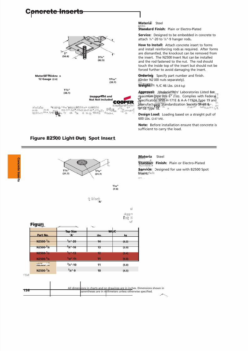
7/18/2019 PH Pipe Hanger Catalog
http://slidepdf.com/reader/full/ph-pipe-hanger-catalog 138/224
Concrete Inserts
Material: Steel
St an dar d Finish: Plain or Electro-Plated
Ser vice: Designed to be embedded in concrete toattach 1 / 4"-20 to 7 / 8"-9 hanger rods .
How to Inst all: Attach concrete insert to formsand install reinforcing rods as required. After formsare dismantled, the knockout can be removed from
the insert. The N2500 Insert Nut can be installedand the rod fastened to the nut. The rod shouldtouch the inside top of the insert but should not beforced further to avoid damaging the insert.
Ordering: Specify part number and finish.(Order N2500 nuts separately).
Wei ght: Wt./C 46 Lbs. (20.8 kg)
Approvals: Underwriters' Laboratories Listed formaximum pipe size 6" (150) . Complies with FederalSpecification WW-H-171E & A-A-1192A Type 19 andManufacturers Standardization Society SP-69 &SP-58 Type 18.
Design Lo ad: Loading based on a straight pull of600 Lbs. (2.67 kN) .
Note: Before installation ensure that concrete issufficient to carry the load.
Material: Steel
St andard Finish: Plain or Electro-Plated
Ser vice: Designed for use with B2500 Spot
Insert .Ordering: Specify part number and finish.
Figure B2500 Light Duty Spot Inser t
Figure N2500 Steel Inser t Nut
'A'
31 / 4"(8 2.5)
1 9 / 16 "(39.7)
1 1 / 2"(3 8.1)
11 / 4"
(31.7)
11 / 4"(31.7)
5 / 16 "(7.9)
Hanger Ro d andNu t N ot Included
Materi al Thicknes s12 Gauge (2.6)
2"(50.8)
Tap Si ze Wt./CPart No. 'A' Lbs. k g
N250 0-1 / 4 1 / 4"-20 14 (6.3)
N250 0-3 / 8 3 / 8"-16 13 (5.9)
N250 0-1 / 2 1 / 2"-13 12 (5.4)
N250 0-5 / 8 5 / 8"-11 11 (5.0)
N250 0-3 / 4 3 / 4"-10 11 (5.0)
N250 0-7 / 8 7 / 8"-9 10 (4.5)
136All dimensions in charts and on drawings are in inches. Dimensions shown in
parentheses are in millimeters unless otherwise specified.
UL®
C onc r et eI ns er t s
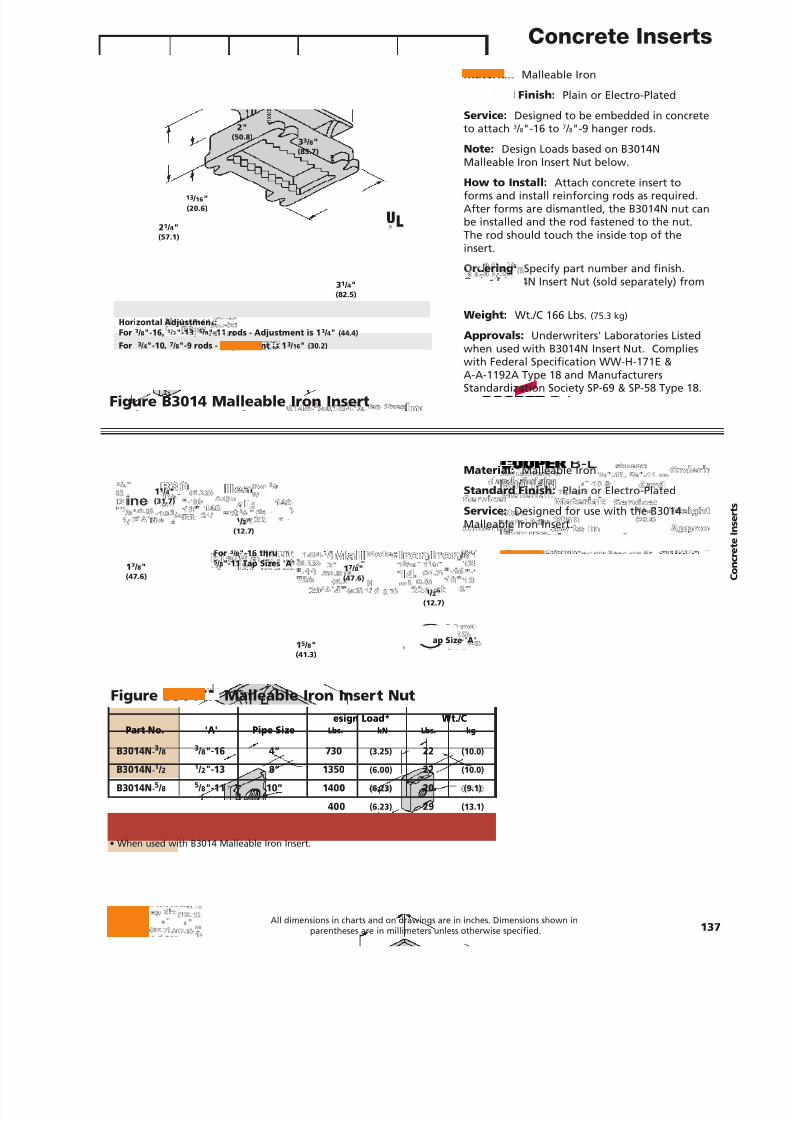
7/18/2019 PH Pipe Hanger Catalog
http://slidepdf.com/reader/full/ph-pipe-hanger-catalog 139/224
Concrete Inserts
Material: Malleable Iron
Stan dard Finish: Plain or Electro-Plated
Service: Designed to be embedded in concreteto attach 3 / 8"-16 to 7 / 8"-9 hanger rods.
Note: Design Loads based on B3014NMalleable Iron Insert Nut below.
How to In st all: Attach concrete insert toforms and install reinforcing rods as required.After forms are dismantled, the B3014N nut canbe installed and the rod fastened to the nut.The rod should touch the inside top of theinsert.
Ordering: Specify part number and finish.Order B3014N Insert Nut (sold separately) frombelow.
Weight: Wt./C 166 Lbs. (75.3 kg)
Approvals: Underwriters' Laboratories Listedwhen used with B3014N Insert Nut. Complieswith Federal Specification WW-H-171E &A-A-1192A Type 18 and ManufacturersStandardization Society SP-69 & SP-58 Type 18.
Figure B3014 Malleable Iron Insert
Figure B3014N Malleable Iron Inser t Nut
Hori zontal Adju stment:For 3 / 8"-16, 1 / 2"-13, 5 / 8"-11 ro ds - Adju stm ent is 1 3 / 4" (44.4)
For 3 / 4"-10 , 7 / 8"-9 rod s - Adjustment is 1 3 / 16" (30. 2)
2"(50.8) 33 / 8"
(85.7)
17 / 8"(47.6)
11 / 4"(31.7)
1 / 2"(12.7 )
1 / 2"(12.7)
17 / 8"(47.6)
15 / 8"(41. 3)
3 1 / 4"(8 2.5)
21 / 4"(57.1)
13 / 16 "(20.6)
For 3 / 4"-10 &7 / 8"-9 Tap Siz e 'A'
For3 / 8"-16 thru5 / 8"-11 Tap Sizes 'A'
Tap Size UL Max. D esi gn Load* W t./ CPar t N o. 'A' Pip e Si ze Lbs. kN L bs. kg
B3014N -3 / 8 3 / 8"-16 4” 730 (3.25) 22 (10.0)
B3014N -1 / 2 1 / 2"-13 8” 1350 (6.0 0) 22 (10.0)
B3014N -5 / 8 5 / 8"-11 10” 140 0 (6.23) 20 (9.1)
B3014N -3 / 4 3 / 4"-10 10” 140 0 (6.23) 29 (13.1)
B3014N -7 / 8 7 / 8"-9 10” 140 0 (6.23) 29 (13.1)
• When used with B3014 Malleable Iron Insert.
All dimensions in charts and on drawings are in inches. Dimensions shown inparentheses are in millimeters unless otherwise specified. 137
Material: Malleable Iron
Stan dard Finish: Plain or Electro-Plated
Service: Designed for use with the B3014Malleable Iron Insert.
Ordering: Specify part number and finish.
UL®
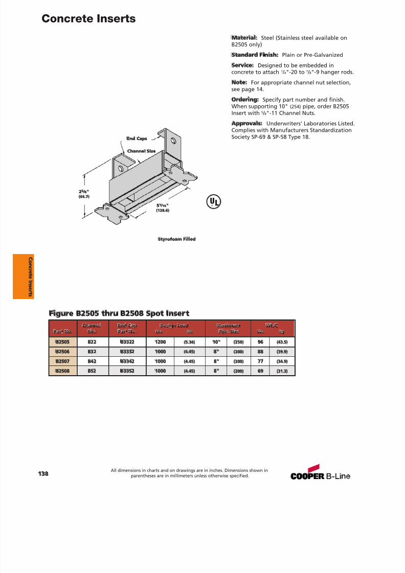
7/18/2019 PH Pipe Hanger Catalog
http://slidepdf.com/reader/full/ph-pipe-hanger-catalog 140/224
Concrete Inserts
Material: Steel (Stainless steel available onB2505 only)
St an dard Finish: Plain or Pre-Galvanized
Service: Designed to be embedded inconcrete to attach 1 / 4"-20 to 7 / 8"-9 hanger rods.
Note: For appropriate channel nut selection,see page 14.
Ord erin g: Specify part number and finish.When supporting 10" (254) pipe, order B2505Insert with 5 / 8"-11 Channel Nuts.
Approvals: Underwriters' Laboratories Listed.Complies with Manufacturers StandardizationSociety SP-69 & SP-58 Type 18.
Figure B2505 thru B2508 Spot Inser t
Styr ofo am Fille d
End Caps
Channel Size
25 / 8"(66.7)
5 1 / 16 "(128.6)
Channel End C ap Design Load Ma ximum W t./CPar t No. Siz e Part No. Lbs. kN Pipe Si ze Lbs. kg
B2505 B2 2 B332 2 120 0 (5.3 4) 10" (250) 96 (43.5)
B2506 B3 2 B333 2 10 00 (4.45) 8" (200) 88 (39.9)
B2507 B4 2 B334 2 10 00 (4.45) 8" (200) 77 (34.9)
B2508 B52 B 335 2 10 00 (4.45) 8" (200) 69 (31.3)
138All dimensions in charts and on drawings are in inches. Dimensions shown in
parentheses are in millimeters unless otherwise specified.
UL®
C onc r et eI ns er t s
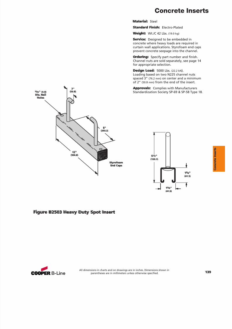
7/18/2019 PH Pipe Hanger Catalog
http://slidepdf.com/reader/full/ph-pipe-hanger-catalog 141/224
Concrete Inserts
All dimensions in charts and on drawings are in inches. Dimensions shown inparentheses are in millimeters unless otherwise specified. 139
Material: Steel
Standard Finish: Electro-Plated
Weight: Wt./C 42 Lbs. (19.0 kg)
Ser vice: Designed to be embedded inconcrete where heavy loads are required incurtain wall applications. Styrofoam end capsprevent concrete seepage into the channel.
Ordering: Specify part number and finish.Channel nuts are sold separately, see page 14for appropriate selection.
Design Load: 5000 Lbs. (22.2 kN ).Loading based on two N225 channel nutsspaced 3” (76.2 mm) on center and a minimumof 2” (50.8 mm) from the end of the insert.
Approvals: Complies with ManufacturersStandardization Society SP-69 & SP-58 Type 18.
Figure B2503 Heavy Duty Spot Insert
15 / 8”(41. 3)
5 1 / 2”(139.7)
15 / 8”(41. 3)
StyrofoamEnd C aps
2"(50.8)
8"(203.2)
12"(30 4.8)
5 / 32" (4.0)Dia. Nail
Holes
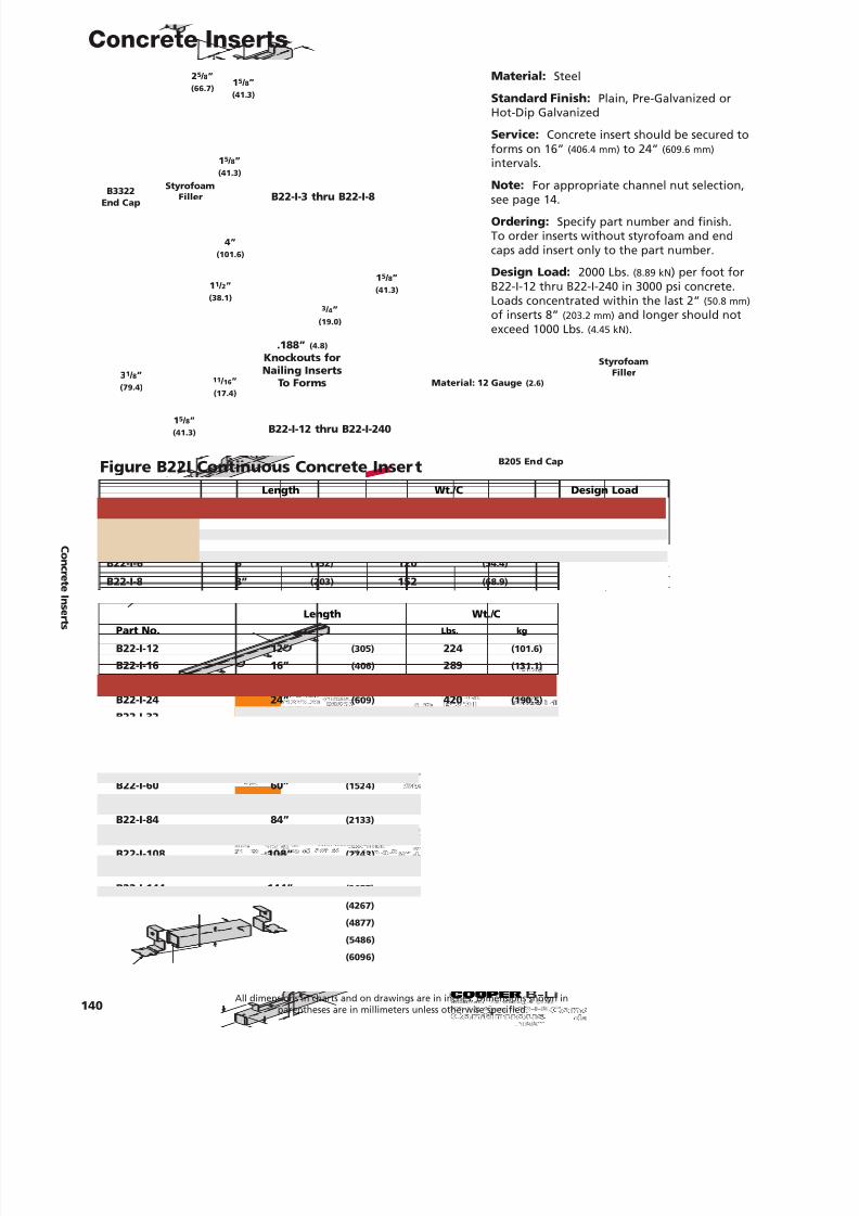
7/18/2019 PH Pipe Hanger Catalog
http://slidepdf.com/reader/full/ph-pipe-hanger-catalog 142/224
Length Wt./ C De sign Lo adPart No. Lbs. kg Lbs. kN
B22-I-3 3” (7 6) 72 (32.6) 50 0 (2.22)
B22-I- 4 4” (101) 88 (39.9) 80 0 (3.5 6)
B22-I- 6 6” (152) 120 (54.4) 1000 (4.45)
B22-I-8 8” (20 3) 152 (68.9) 1200 (5.34)
Concrete Inserts
140All dimensions in charts and on drawings are in inches. Dimensions shown in
parentheses are in millimeters unless otherwise specified.
Length W t./ CPar t No. Lbs. kg
B22-I-12 12” (305) 224 (101.6)
B22-I-16 16” (40 6) 28 9 (131.1)
B22-I-20 20” (5 08) 353 (16 0.1)
B22-I-24 24” (60 9) 420 (19 0.5)
B22-I-32 32” (813) 553 (25 0.8)
B22-I-36 36” (914) 620 (281.2)
B22-I-40 40” (1016) 686 (311.1)
B22-I-4 8 4 8” (1219) 820 (371.9)
B22-I-60 60” (152 4) 1018 (4 61.7)
B22-I-72 72” (182 9) 1218 (552.5)B22-I-84 84” (2133) 1417 (6 42.7)
B22-I-96 9 6” (24 38) 1616 (733.0)
B22-I-108 10 8” (274 3) 1816 (8 23.7)
B22-I-120 12 0” (30 48) 2016 (914.4)
B22-I-144 14 4” (3657) 2416 (1095.9)
B22-I-168 16 8” (4267) 2816 (1277.3)
B22-I-192 19 2” (4 877) 3216 (145 8.7)
B22-I-216 216” (54 86) 3616 (16 40.2)
B22-I-240 240” (609 6) 4016 (18 21.6)
B22-I-3 thru B22-I-8
B22-I-12 thru B22-I-240
1 5 / 8”(41. 3)
1 5 / 8”(41.3)
2 5 / 8”(66.7)
B3322End C ap
Styrofoam
Filler
M aterial: 12 Gauge (2.6)
1 5 / 8”(41.3)
15 / 8”(41.3)
1 1 / 2”(38.1)
3 1 / 8”(79.4)
3 / 4”(19.0)
11 / 16 ”(17.4)
.188” (4.8)
Kn o ckout s forNailin g Insert s
To F orm s
4”(101.6)
Figure B22I Continuous Concrete Inser t
Material: Steel
Stan dard Finish: Plain, Pre-Galvanized orHot-Dip Galvanized
Service: Concrete insert should be secured toforms on 16” (406.4 mm) to 24” (609.6 mm)intervals.
Note: For appropriate channel nut selection,
see page 14.Ord erin g: Specify part number and finish.To order inserts without styrofoam and endcaps add insert only to the part number.
Design Load: 2000 Lbs. (8.89 kN ) per foot forB22-I-12 thru B22-I-240 in 3000 psi concrete.Loads concentrated within the last 2” (50.8 mm)of inserts 8” (203.2 mm) and longer should notexceed 1000 Lbs. (4.45 kN) .
B205 En d C ap
St yrofoamFiller
C onc r et eI ns er t s
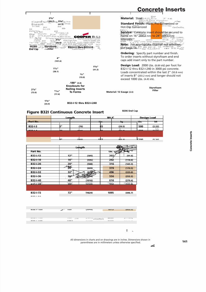
7/18/2019 PH Pipe Hanger Catalog
http://slidepdf.com/reader/full/ph-pipe-hanger-catalog 143/224
Concrete Inserts
All dimensions in charts and on drawings are in inches. Dimensions shown inparentheses are in millimeters unless otherwise specified. 141
Length W t. /C Design LoadPar t No. Lbs. kg Lb s. kN
B32-I-3 3” (76) 65 (29.5) 50 0 (2. 22)
B32-I- 4 4” (101) 80 (36. 3) 800 (3.56)
B32-I- 6 6” (152) 10 8 (49.0) 10 00 (4. 45)
B32-I-8 8” (203) 137 (6 2.1) 120 0 (5. 34)
Leng th Wt./CPart No. Lbs. kg
B32-I-12 12” (305) 202 (91.6)
B32-I-16 16” (40 6) 26 2 (118.8)
B32-I-20 20” (508) 316 (143.3)
B32-I-24 24” (609) 376 (170.5)
B32-I-3 2 32” (813) 49 6 (225.0)
B32-I-36 36” (914) 556 (252.2)
B32-I-40 40” (1016) 616 (279.4)
B32-I-48 48” (1219) 736 (333.8)
B32-I- 60 60” (1524) 915 (415.0)
B32-I-72 72” (1829) 1095 (496.7)B32-I-84 84” (2133) 1274 (577.9)
B32-I-9 6 96” (2438) 1453 (659.0)
B32-I-108 10 8” (274 3) 1633 (740.7)
B32-I-120 120” (304 8) 1813 (822.3)
B32-I-144 14 4” (3657) 2173 (985.6)
B32-I-168 16 8” (4267) 2533 (1148.9)
B32-I-192 192” (4877) 2893 (1312.2)
B32-I-216 216” (5486) 3253 (1475.5)
B32-I-240 240” (6096) 3613 (1638.8)
B32-I-3 thru B32-I -8
B32-I-12 thru B32-I-240
1 5 / 8”(41.3)
1 3 / 8”(34.9)
2 5 / 8”(66.7)
B3332End Cap
Styrofo amFiller
Material: 12 G au g e (2.6)
1 5 / 8”(41.3)
13 / 8”(34.9)
11 / 2”(38.1)
2 7 / 8”(73.0)
3 / 4”(19.0)
11 / 16 ”(17.4)
.18 8” (4.8)
Knockou ts forNailing Ins er t s
To F orms
4”(101.6)
Figure B32I Continuous Concrete Insert
Material: Steel
Standard Finish: Plain, Pre-Galvanized orHot-Dip Galvanized
Ser vice: Concrete insert should be secured toforms on 16” (406.4 mm) to 24” (609.6 mm)intervals.
Note: For appropriate channel nut selection,
see page 14.Ordering: Specify part number and finish.To order inserts without styrofoam and endcaps add insert only to the part number.
Design Load: 2000 Lbs. (8.89 kN ) per foot forB32-I-12 thru B32-I-240 in 3000 psi concrete.Loads concentrated within the last 2” (50.8 mm)of inserts 8” (203.2 mm) and longer should notexceed 1000 Lbs. (4.45 kN) .
B20 6 End C ap
St yrofo amFiller
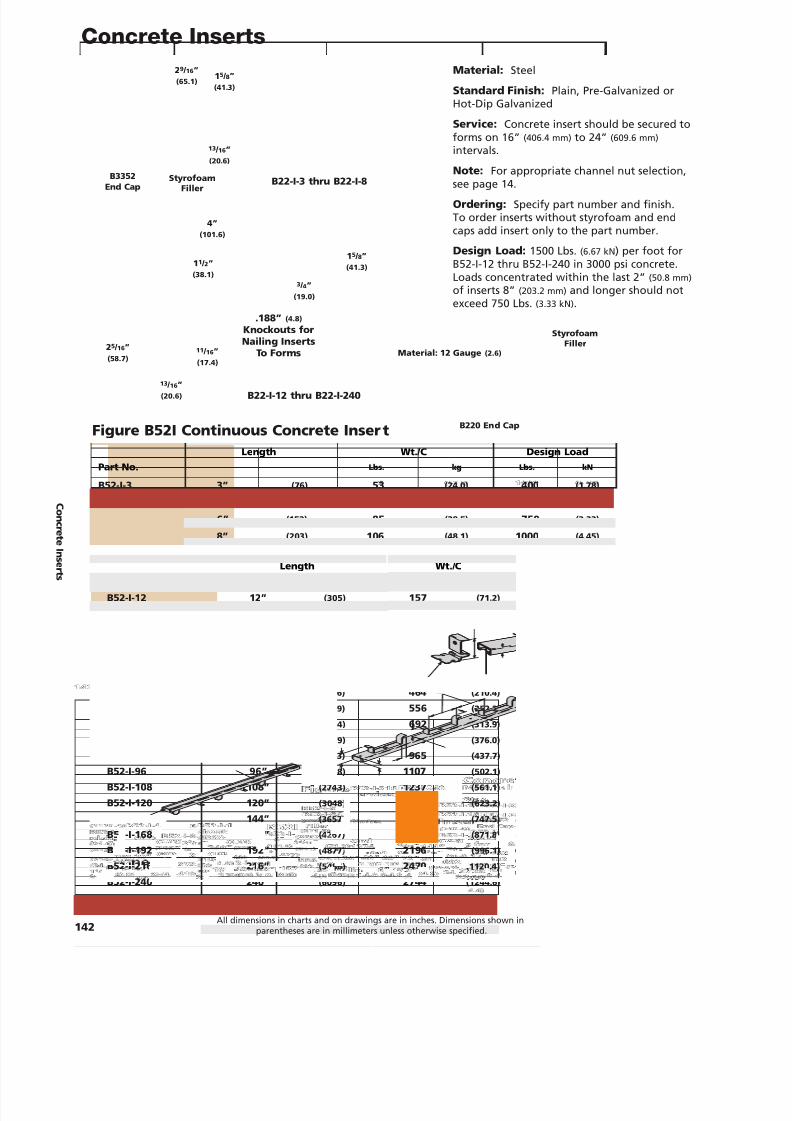
7/18/2019 PH Pipe Hanger Catalog
http://slidepdf.com/reader/full/ph-pipe-hanger-catalog 144/224
Concrete Inserts
142All dimensions in charts and on drawings are in inches. Dimensions shown in
parentheses are in millimeters unless otherwise specified.
Length Wt./ C De sign Lo adPart No. Lbs. kg Lbs. kN
B52-I-3 3” (7 6) 53 (24.0) 40 0 (1.78)
B52-I-4 4” (101) 63 (28.6) 50 0 (2.22)
B52-I- 6 6” (152) 85 (38.5) 750 (3.33)
B52-I-8 8” (20 3) 10 6 (48.1) 1000 (4.45)
Length W t./ CPar t No. Lbs. kg
B52-I-12 12” (305) 157 (71.2)
B52-I-16 16” (40 6) 202 (91.6)
B52-I-20 20” (5 08) 237 (107.5)
B52-I-24 24” (60 9) 28 2 (127.9)
B52-I-32 32” (813) 373 (169.2)
B52-I-36 36” (914) 419 (19 0.0)
B52-I-40 40” (1016) 46 4 (210.4)
B52-I-4 8 4 8” (1219) 556 (25 2.2)
B52-I-60 60” (152 4) 692 (313.9)
B52-I-72 72” (182 9) 829 (376.0)B52-I-84 84” (2133) 965 (4 37.7)
B52-I-96 9 6” (24 38) 1107 (50 2.1)
B52-I-108 108” (274 3) 12 37 (561.1)
B52-I-120 120” (30 48) 1374 (62 3.2)
B52-I-144 144” (3657) 16 48 (747.5)
B52-I-168 168” (4267) 192 2 (871.8)
B52-I-192 192” (4 877) 219 6 (99 6.1)
B52-I-216 216” (54 86) 247 0 (1120.4)
B52-I-240 240” (609 6) 274 4 (124 4.6)
B22-I-3 thru B22-I-8
B22-I-12 thru B22-I-240
1 5 / 8”(41. 3)
13 / 16 ”(2 0.6)
29 / 16 ”(65.1)
B3352End Cap
St yrofoamFiller
M ateri al: 12 Gauge (2.6)
15 / 8”(41.3)
13 / 16 ”(20.6)
1 1 / 2”(38.1)
2 5 / 16 ”(5 8.7)
3 / 4”(19.0)
11 / 16 ”(17.4)
.188” (4.8)
Kn o ckout s forNailin g Insert s
To F orm s
4”(101.6)
Figure B52I Continuous Concrete Inser t
Material: Steel
Stan dard Finish: Plain, Pre-Galvanized orHot-Dip Galvanized
Service: Concrete insert should be secured toforms on 16” (406.4 mm) to 24” (609.6 mm)intervals.
Note: For appropriate channel nut selection,
see page 14.Ord erin g: Specify part number and finish.To order inserts without styrofoam and endcaps add insert only to the part number.
Design Load: 1500 Lbs. (6.67 kN ) per foot forB52-I-12 thru B52-I-240 in 3000 psi concrete.Loads concentrated within the last 2” (50.8 mm)of inserts 8” (203.2 mm) and longer should notexceed 750 Lbs. (3.33 kN) .
B220 En d C ap
St yrofoamFiller
C onc r et eI ns er t s
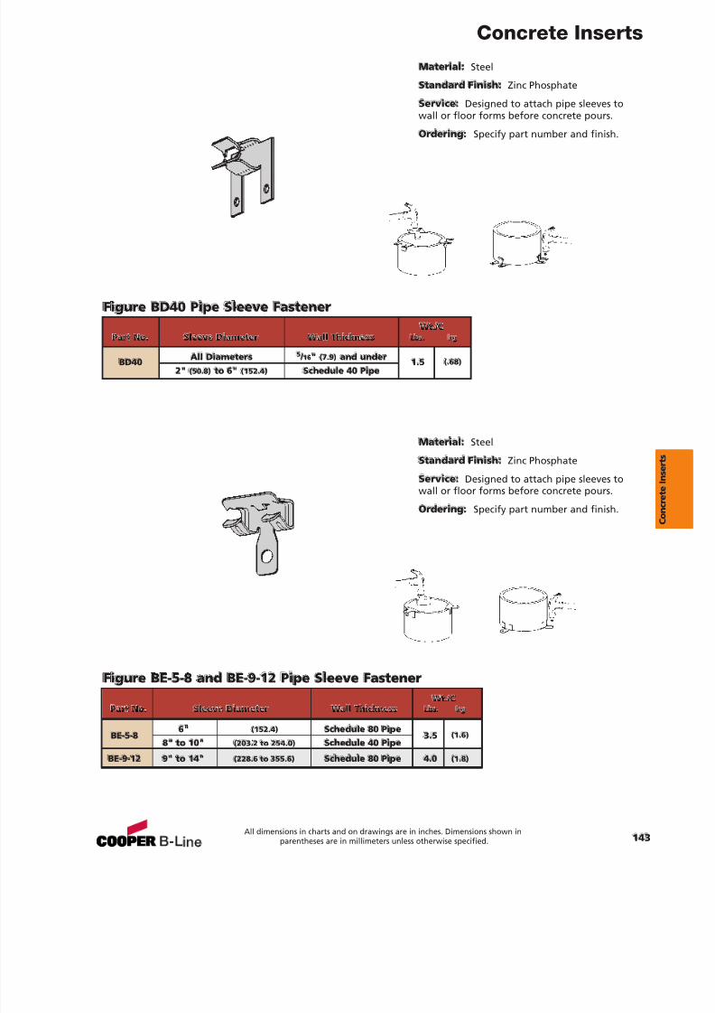
7/18/2019 PH Pipe Hanger Catalog
http://slidepdf.com/reader/full/ph-pipe-hanger-catalog 145/224
Concrete Inserts
Material: Steel
Stan dard Finish: Zinc Phosphate
Service: Designed to attach pipe sleeves towall or floor forms before concrete pours.
Ordering: Specify part number and finish.
Material: Steel
Stan dard Finish: Zinc Phosphate
Service: Designed to attach pipe sleeves towall or floor forms before concrete pours.
Ordering: Specify part number and finish.
Figure BD40 Pipe Sleeve Fastener
Figure BE-5-8 and BE-9-12 Pipe Sleeve Fastener
Wt./ CPart No. Sleeve Diameter W all Thickn ess Lbs. kg
BD40 All Diameter s 5 / 16 " (7.9) an d und er 1.5 (.68)2" (5 0.8) to 6" (152. 4) Sch edule 40 Pipe
Wt./CPar t No. Sleev e Diam eter W all Thickness Lbs. kg
BE-5-86" (152.4) Sche dule 80 Pip e
3.5 (1.6)8" to 10" (203. 2 to 25 4.0) Sche dule 40 Pip e
BE-9 -12 9" to 14" (228.6 to 355.6) Sche dule 80 Pip e 4.0 (1.8)
All dimensions in charts and on drawings are in inches. Dimensions shown inparentheses are in millimeters unless otherwise specified. 143
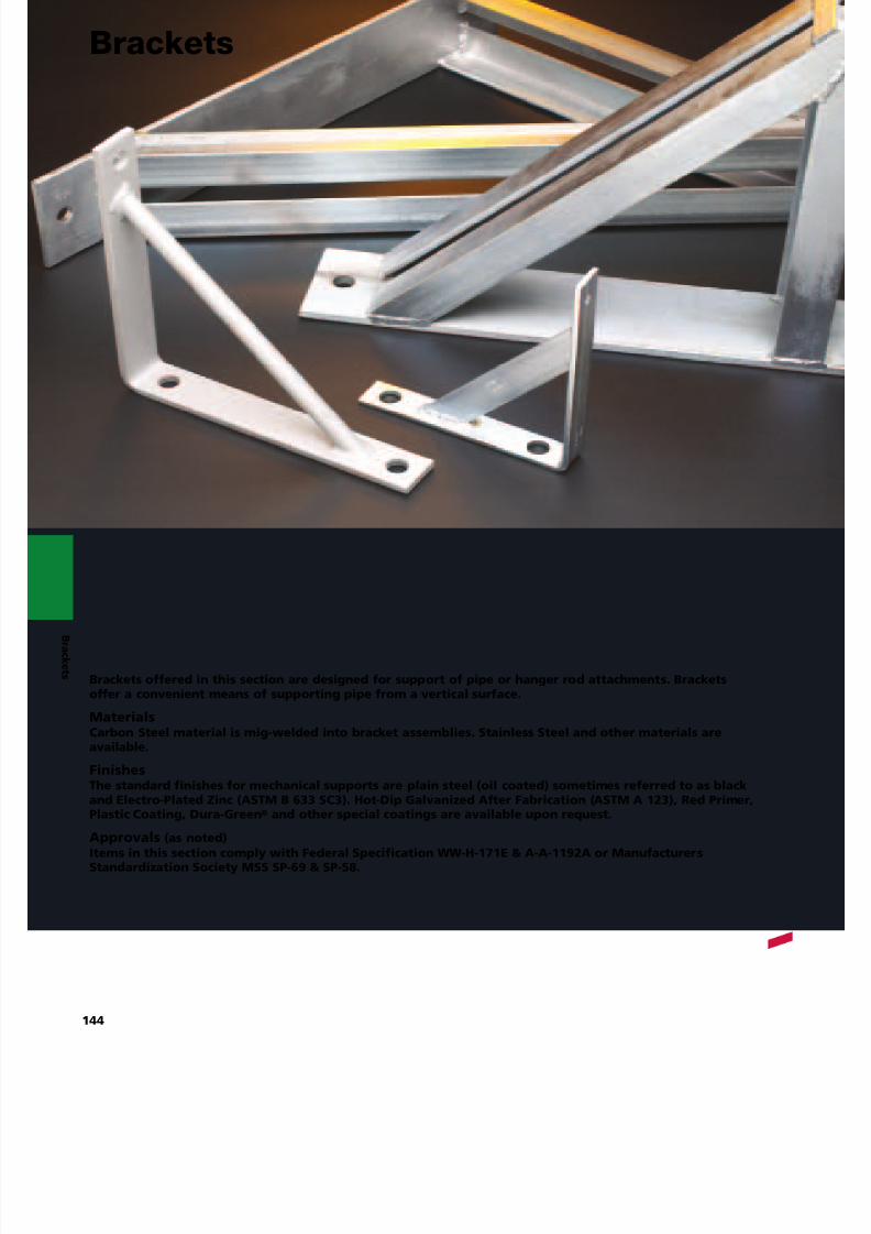
7/18/2019 PH Pipe Hanger Catalog
http://slidepdf.com/reader/full/ph-pipe-hanger-catalog 146/224
B r a c k e t s Bra cket s offere d in this se ction are designed for supp or t of pipe or hanger ro d at t a chment s. Bracket s
of fer a convenient means of supp orting pipe from a vertic al surface.
MaterialsCarbon Ste el material is mig-weld ed into bracket a ssemblies. St ainles s Steel and oth er materials areavailable.
FinishesThe stan d ard finishes for mechanical supports are plain steel (oil coated) sometim es referred to as blackan d Electro -Plate d Zinc (ASTM B 633 SC3). Hot -Dip Galvanized Af ter Fabrication (ASTM A 123), Red Primer,
Plastic Coating, Dura-Green ® and oth er spe cial coatings are available upon re quest.Approvals (as noted)Items in this section comply with F e deral Sp e cification W W-H -171E & A-A-1192A or M anufacturer sSt an dardiz ation So ciet y MSS SP-69 & SP-58.
144
Brackets
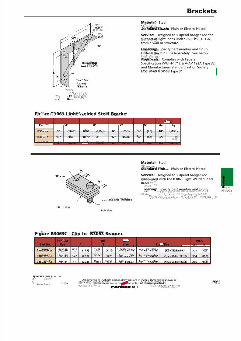
7/18/2019 PH Pipe Hanger Catalog
http://slidepdf.com/reader/full/ph-pipe-hanger-catalog 147/224
Brackets
Figure B3063 Light Welded Steel Bracket
Figure B3063CP Clip for B3063 Bracket
Material: Steel
Stan dard Fini sh: Plain or Electro-Plated
Service: Designed to suspend hanger rod forsupport of light loads under 750 Lbs. (3.33 kN)from a wall or structure.
Ordering: Specify part number and finish.Order B3063CP Clips separately. See below.
Approvals: Complies with FederalSpecification WW-H-171E & A-A-1192A Type 32and Manufacturers Standardization SocietyMSS SP-69 & SP-58 Type 31.
Material: Steel
Stan dard Finish: Plain or Electro-PlatedService: Designed to suspend hanger rodwhen used with the B3063 Light Welded SteelBracket.
Ordering: Specify part number and finish.
Han ger Ro dNot Inclu de d
Bolt and Nut Include d
Steel Size
'B' Dia.
Bol t Size
'B'
1"(25.4)
1"(25.4)
2"(50.8)
1"(25.4)
13 / 16 " Di a.(2 0.6)
3 Hole s
'C'
'A'
'A'
'A'
'D'
'A'
For Ro d Dia. Bolt W t./ CPar t No. Siz e 'A' 'B' Si ze St eel Siz e Lbs. k g
B3063CP-3 / 8 3 / 8"-16 9 / 16" (14.3) 7 / 16" (11.1) 3 / 8"-16x 1 3 / 4" 3 / 8" x 2" x 3 5 / 8" (9.5 x 5 0.8 x 92.1) 156 (70.7)
B3063CP-1 / 2 1 / 2"-13 7 / 8" (22.2) 9 / 16" (14.3) 1 / 2"-13 x 2" 3 / 8" x 2 " x 4 3 / 8" (9.5 x 50.8 x 111.1) 194 (88.0)
B3063CP-5 / 8 5 / 8"-11 1" (25.4) 11 / 16" (17.5) 5 / 8"-11 x 2" 3 / 8" x 2 " x 4 1 / 2" (9.5 x 50.8 x 114.3) 206 (93.4)
Wt./ CPar t No. 'A' 'B' 'C' 'D' Lbs. k g
B3063-1 9" (228.6) 61 / 2" (165.1) 8" (203.2) 3 / 8" (9.5) 409 (185.5)
B3063-2 13" (330.2) 101 / 2" (266.7) 12" (304.8) 3 / 8" (9.5) 620 (281. 2)
B3063-3 19" (482.6) 161 / 2" (419.1) 18" (457.2) 3 / 8" (9.5) 936 (424.5)
All dimensions in charts and on drawings are in inches. Dimensions shown inparentheses are in millimeters unless otherwise specified. 145

7/18/2019 PH Pipe Hanger Catalog
http://slidepdf.com/reader/full/ph-pipe-hanger-catalog 148/224
Brackets
Material: Steel
St an dard Finish: Plain or Electro-Plated
Service: Designed for suspending light loadsat fixed distances from walls or structures.
Ord erin g: Specify part number and finish.
Material: Steel
St an dard Finish: Plain or Electro-Plated
Service: Designed for supporting pipe fromwalls or structures where lateral adjustment isrequired.
Ord erin g: Specify part number and finish.
Figure B3068 Light Duty Welded Bracket
Figure B3064 Adjustable Stru t Bracket
Steel Si ze'B'
1"(25. 4)
1"(25.4)
13 / 16 " Dia.(20.6)
2 H oles
9 / 16 " Di a.(14. 3)
2 Holes
For 3 / 8"-16 rod.Hang er Ro d
Not Inclu d ed
7 / 16 " Dia.(11.1)
'C'
'A'
2"(50.8)
B22 Ch ann el
B32 Chann el
'B'
11 / 4"(31.7)
11 / 4"(31.7)
15 / 8"(41.2)
3 / 8" Dia.(9.5)
45 o'A'
Design Lo ad W t./CPart No. 'A' 'B' Lbs. kN L bs. k g
B3064-1 15" (381.0) 12" (30 4.8) 120 0 (5.34) 660 (299.4)
B3064-2 21" (533.4) 18" (45 7.2) 800 (3.5 6) 1004 (455.4)
B3064-3 27" (685.8) 24" (60 9.6) 600 (2.67) 1346 (610.5)
Design Loa d Wt. / CPar t No. 'A' 'B' 'C' St eel Siz e Lbs. kN L bs. kg
B3068-1 10" (254.0) 61 / 2" (165.1) 9" (228.6) 1 / 4" x 1 1 / 2" (6.3 x 38.1) 730 (3.25) 284 (128. 8)
B3068-2 14" (355.6) 10 1 / 2" (266.7) 13" (330.2) 1 / 4" x 1 1 / 2" (6.3 x 38.1) 730 (3.25) 429 (194.6)
B3068-3 20" (508.0) 16 1 / 2" (419.1) 19" (482.6) 3 / 8" x 2 " (9.5 x 50. 8) 730 (3.25) 1279 (580.1)
146All dimensions in charts and on drawings are in inches. Dimensions shown in
parentheses are in millimeters unless otherwise specified.
B r a c k e t s

7/18/2019 PH Pipe Hanger Catalog
http://slidepdf.com/reader/full/ph-pipe-hanger-catalog 149/224
Brackets
Figure B3065 Angle Iron Bracket
Material: Steel (Stainless steel available)
Stan dard Finish: Plain or Electro-Plated
Service: Designed for suspending mediumloads at fixed distances from walls or structures.
Ordering: Specify part number and finish.
'B'
13 / 16 " Di a.(20.6)
2 Holes
Angle Iron Size
'A'(Ro d Si ze)
Hanger Ro dNot In clu ded
'C'
'D'
'D'
'E'
For Ro dPart No. Size 'A' 'B' 'C' 'D' 'E'
B3065-1 5 / 8"-11 11 1 / 4" (285.7) 7" (177. 8) 10" (254.0) 11 / 8" (28.6)
B3065-2 5 / 8"-11 13 1 / 4" (336.5) 9" (228.6) 12" (304.8) 11 / 8" (28.6)
B3065-3 3 / 4"-10 15 1 / 4" (387.3) 11" (279. 4) 14" (355.6) 13 / 8" (34.9)
B3065- 4 1"-8 19 3 / 4" (501.6) 15" (381.0) 18" (457.2) 13 / 4" (44.4)
Design Load Wt. / CPart No. Angle Iron Siz e Lbs. kN L bs. kg
B3065-1 1 / 4" x 2" x 2" (6.3 x 50.8 x 50.8) 120 0 (5.34) 793 (359.7)
B3065-2 1 / 4" x 2" x 2" (6.3 x 50.8 x 50.8) 120 0 (5.34) 974 (441.8)
B3065-3 1 / 4" x 2 1 / 2" x 2 1 / 2" (6.3 x 63.5 x 63.5) 120 0 (5.34) 1480 (671.3)
B3065-4 1 / 4" x 3" x 3" (6.3 x 76.2 x 76.2) 120 0 (5.34) 234 3 (1062.8)
All dimensions in charts and on drawings are in inches. Dimensions shown inparentheses are in millimeters unless otherwise specified. 147

7/18/2019 PH Pipe Hanger Catalog
http://slidepdf.com/reader/full/ph-pipe-hanger-catalog 150/224
Brackets
Figure B3066 Medium Duty Angle Bracket
Material: Steel; (Stainless Steel available)
Stan dard Finish: Plain or Electro-Plated
Service: Designed for suspending pipeloads under 1500 Lbs. (6.67 kN) from walls orstructures.
Ord erin g: Specify part number and finish.
Approval s: Complies with FederalSpecification WW-H-171E & A-A-1192A Type 33and Manufacturers Standardization SocietyMSS SP-69 & SP-58 Type 32.
Part No. 'A' 'B' 'C' 'D'B3066- 0 18" (457.2) 5" (127.0) 151 / 2" (393.7) 12" (304.8)
B3066-1 24" (609.6) 5" (127.0) 211 / 2" (546.1) 18" (457. 2)
B3066-2 30" (762.0) 6" (152.5) 27 1 / 2" (698.5) 24" (609.6)
Design Lo ad W t./ CPar t N o. An gle Ir on Siz e Lbs. kN Lbs. kg
B3066-0 3 / 16 " x 1 1 / 2" x 1 1 / 2" (4.8 x38.1 x38 .1) 150 0 (6.67) 1819 (825.1)
B3066-13 / 1 6 " x 1
3 / 4 " x 1
3 / 4 " (4.8 x 4 4.4 x 4 4.4) 150 0 (6.67) 1803 (1271. 4)
B3066-2 1 / 4 " x 2" x2" (6.3 x 5 0.8 x 50.8) 150 0 (6.67) 4973 (2255.7)
148All dimensions in charts and on drawings are in inches. Dimensions shown in
parentheses are in millimeters unless otherwise specified.
B r a c k e t s
An gle Iron Size
'B'
13 / 16 " Dia.
(2 0.6)2 Hole s
21 / 2"
(6 3.5)
3 / 8"(9.5)
1 1 / 4"(31.7)
1"(25.4)
'C'
'A'
'D'

7/18/2019 PH Pipe Hanger Catalog
http://slidepdf.com/reader/full/ph-pipe-hanger-catalog 151/224
Brackets
Figure B3067 Heavy Duty Angle Bracket
Material: Steel (Stainless steel available)
Stan dard Finish: Plain or Electro-Plated
Service: Designed for suspending pipe loadsunder 3000 Lbs. (13.34kN) from walls orstructures.
Ordering: Specify part number and finish.
Approvals: Complies with FederalSpecification WW-H-171E & A-A-1192A Type 34and Manufacturers Standardization SocietyMSS SP-69 & SP-58 Type 33.
Part N o. 'A' 'B' 'C' 'D' 'E'
B3067-0 18" (457.2) 5" (127.0) 15 1 / 4" (387.3) 12" (304.8) 23 / 4" (69.8)
B3067-1 24" (609.6) 6" (152.4) 21 3 / 8" (542.9) 18" (457. 2) 23 / 4" (69.8)
B3067-2 3 0" (762.0) 6" (152.4) 27 1 / 2" (698.5) 24" (609.6) 23 / 4" (69.8)
B3067-3 36" (914.4) 6" (152.4) 331 / 4" (844.5) 30" (762.0) 3" (76.2)
B3067-4 42" (1066.8) 7" (177.8) 39" (990.6) 36" (914.4) 3" (76.2)
B3067-5 50" (1270.0) 7" (177.8) 46" (116 8.4) 42" (1066.8) 31 / 2" (88.9)
Design Lo ad Wt./ CPar t No. 'F' 'G' 'H' Angle Iron Siz e Lbs. kN Lbs. k g
B3067- 0 1 3 / 8" (34.9) - - 13 / 16" (20.6) 1 / 4" x 1 1 / 2"x2" (4.8x 3 8.1 x 50.8) 3000 (13.34) 258 4 (1172.1)
B3067-1 1 7 / 16" (36.5) 23 / 4" (69.8) 15 / 16" (23.8) 3 / 8"x2"x2" (9.5x 5 0.8 x 50.8) 3000 (13.34) 5385 (244 2.6)
B3067-2 1 1 / 2" (38.1) 21 / 2" (63.5) 11 / 16" (27.0) 5 / 16" x 2 " x 2 1 / 2" (7.9 x 50.8x 6 3.5) 3000 (13.34) 6841 (310 3.1)
B3067-3 1 5 / 8" (41.3) 21 / 2" (63.5) 11 / 16" (27.0) 5 / 16" x 2 " x 2 1 / 2" (7.9 x 50.8x 6 3.5) 3000 (13.34) 8439 (3827.9)
B3067- 4 1 1 / 2" (38.1) 31 / 2" (88.9) 11 / 16" (27.0) 3 / 8" x 2 1 / 2"x3 1 / 2" (9.5x 63.5 x 88.9) 3000 (13.34) 14497 (6575.8)
B3067-5 1 1 / 2" (38.1) 31 / 2" (88.9) 11 / 16" (27.0) 3 / 8" x 2 1 / 2"x3 1 / 2" (9.5x 63.5 x 88.9) 3000 (13.34) 17015 (7718.0)
All dimensions in charts and on drawings are in inches. Dimensions shown inparentheses are in millimeters unless otherwise specified. 149
'B'
'H'3 Holes
Only one hole intop for B 3067-0
1 / 2"(12.7)
1"(25.4)
Angle Ir on Size'C'
'A'
'D'
'F'
'E'
'G'

7/18/2019 PH Pipe Hanger Catalog
http://slidepdf.com/reader/full/ph-pipe-hanger-catalog 152/224
Upper at t achments of fere d in this se ction are design e d to su spend hanger rods from beams, con crete,an d other structural surfaces by bolting or welding.
MaterialsCarbon Steel and Malleable Iron are u sed in the manu fa cturing of upper at t a chment s and provide th ehigh s trength prop er ties required. Stainless Steel an d other materials are available.
FinishesThe stan d ard finishes for mechanical supports are plain steel (oil coated) sometim es referred to as blackan d Electro -Plate d Zinc (ASTM B 633 SC3). Hot -Dip Galvanized Af ter Fabrication (ASTM A 123), Red Primer,
Plastic Coating, Dura-Green ® and oth er spe cial coatings are available upon re quest.Note: Due to the design of some produc t s, (threads, connecting hardware, swivels, etc.) items mayor may n ot b e uniformly coated with special finishes. In some c ases, the hanger itself may be coated,however, the hardware may be supplied Electro -Plate d , copper plated , or in st ainless steel.
Approvals (as noted)Items in this section comply with F ederal Specification W W-H -171E & A-A-1192A or M anufacturer sStan dardiz ation So ciet y MSS SP -69 & SP -58.
150
Upper Attachments
Upper
m

7/18/2019 PH Pipe Hanger Catalog
http://slidepdf.com/reader/full/ph-pipe-hanger-catalog 153/224
Upper Attachments
Material: Malleable Iron (Stainless Steel Type304 available)
Stan dard Finish: Plain or Electro-Plated
Service: Designed for attaching a hanger orsupport rod to beams, ceilings, or walls.
Ordering: Specify part number and finish.
Material: Steel
Stan dard Finish: Pre-Galvanized
Service: Designed for fastening pipe clamps,fixtures, and outlet boxes to the bottom of abar joist.
Ordering: Specify part number and finish.
Figure B3199 Ceiling Flange(Available with Dura -Copper finish as B3199RC T-Size)
Figure B3059 Bar Joist Washer
'A'(Ro d or Pip e Threa d)
Hang er Rod or Pip e NotInclu de d
'B'Overall Hei ght
'B'
27 / 8"(73.0)
2"(50.8)
1 3 / 8"(34.9)
'A'(Ro d Si ze)
Hang er Ro d and Nu tNot Includ ed
'A'Hole Si ze
21 / 4"(57.1)
1 7 / 8"(47.6)
11 / 4"(31.7)
For 1 / 4" Flat H eadMa chine Screw sor Wo od Screw s
Part No.Thread Siz e Design Load W t./C
Rod 'A' Pipe 'B' Lbs. kN Lbs. kg
B319 9P-1 / 4 -- -- 1 / 4"-18 1 / 2" (12.7) 180 (.80) 17 (7.7)
B319 9R-3 / 8 B3199RC T-3 / 8 3 / 8"-16 - - 7 / 16" (11.1) 180 (.80) 13 (5.9)
B3199R- 1 / 2 B3199RCT- 1 / 2 1 / 2"-13 -- 1 / 2" (12.7) 180 (.80) 17 (7.7)
For Hole Size W t./ CPart No. Ro d Size 'A' Steel Size Lbs. kg
B3059- 1 / 4 1 / 4"-2 0 5 / 16" (7.9) 16 Ga. x 1 1 / 4" (1.5 x 31.7) 5 (2.2)
B3059- 3 / 8 3 / 8"-16 7 / 16" (11.1) 16 Ga. x 1 1 / 4" (1.5 x 31.7) 5 (2.2)
B3199RCT
All dimensions in charts and on drawings are in inches. Dimensions shown inparentheses are in millimeters unless otherwise specified. 151

7/18/2019 PH Pipe Hanger Catalog
http://slidepdf.com/reader/full/ph-pipe-hanger-catalog 154/224

7/18/2019 PH Pipe Hanger Catalog
http://slidepdf.com/reader/full/ph-pipe-hanger-catalog 155/224
Upper Attachments
Material: Steel (Stainless steel available)
Standard Finish: Plain or Electro-Plated
Ser vice: Designed for attaching a hanger rod to tothe side of beams or walls.
Ordering: Specify part number and finish.
Approvals: Complies with Federal Specification
WW-H-171E & A-A-1192A Type 35 andManufacturers Standardization Society MSS SP-69 &SP-58 Type 34.
Material: Steel (Stainless steel available)
Standard Finish: Plain or Electro-Plated
Ser vice: Designed for attaching 3 / 8” hanger rod tothe side of beams or walls.
Design Load: 300 Lbs. (1.33kN)
Weight: Wt./C 15 Lbs. (6.8 kg)
Ordering: Specify part number and finish.
Approvals: Complies with Federal SpecificationWW-H-171E & A-A-1192A Type 35 andManufacturers Standardization Society MSS SP-69 &SP-58 Type 34.
Figure B3060 Side Beam Angle Clip
Figure B3060L Light Duty Angle Clip
Material: Steel
Standard Finish: Plain or Electro-Plated
Ser vice: Designed for for attaching hanger rod tothe side of beams or walls.
Design Load: 500 Lbs. (2.22 kN) when installed ineither direction.
Weight: Wt./C 49 Lbs. (22.2 kg)
Ordering: Specify part number and finish.
Approvals: Complies with Federal SpecificationWW-H-171E & A-A-1192A Type 35 andManufacturers Standardization Society MSS SP-69 &SP-58 Type 34.
Figure B3070 Reversible Angle Clip
7 Ga.(4.5)
2"(50.8)
1 7 / 8"(47.6)
9 / 32" Dia(7.1)
2 Hole s
15 / 16"(23.8)
15 / 16 "(2 3.8)1 / 4" Dia
(6. 3)4 Holes
For 1 / 2" -13 r od.9 / 16 " Dia
(14. 3)
For 3 / 8" -16 rod.7 / 16 " Dia
(11.1)
7 / 16 " Dia(11.1)
2 H ol es
15 / 16 "(33.3)
13 / 16 " (20.6)
1 1 / 4"(31.7)
2 3 / 16 "(55.6)
23 / 16 "(55.6)
1 / 2"(12.7)
'A'Hol e Size
'B'
'B'
'C'
'D'
'D'
'T'
Hole Siz e Design Loa d Wt./CPar t N o. 'A' 'B' 'C' 'D' 'T' Lbs. kN L bs. kg
B3060- 3 / 8 7 / 16" (11.1) 23 / 16" (55.6) 2" (50. 8) 11 / 4" (31.7) 1 / 4" (6.3) 305 (1.35) 53 (24.0)
B3060- 1 / 2 9 / 16" (14. 3) 23 / 16" (55.6) 2" (50. 8) 11 / 4" (31.7) 1 / 4" (6.3) 565 (2.51) 51 (23.1)
B3060- 5 / 8 11 / 16" (17.5) 23 / 16" (55.6) 2" (50.8) 11 / 4" (31.7) 1 / 4" (6.3) 909 (4.02) 48 (21.8)
B3060- 3 / 4 13 / 16" (20.6) 3" (76.2) 3" (76. 2) 13 / 4" (44.4) 3 / 8" (9.5) 1355 (6.03) 169 (74.8)
B3060- 7 / 8 15 / 16" (23.8) 4" (101.6) 4" (101.6) 21 / 2" (63.5) 3 / 8" (9.5) 1870 (8.32) 312 (141.5)
B3060-1 1 1 / 16" (27.0) 4" (101.6) 4" (101.6) 21 / 2" (63.5) 1 / 2" (12.7) 2480 (11.0 3) 402 (182.3)
All dimensions in charts and on drawings are in inches. Dimensions shown inparentheses are in millimeters unless otherwise specified. 153

7/18/2019 PH Pipe Hanger Catalog
http://slidepdf.com/reader/full/ph-pipe-hanger-catalog 156/224

7/18/2019 PH Pipe Hanger Catalog
http://slidepdf.com/reader/full/ph-pipe-hanger-catalog 157/224

7/18/2019 PH Pipe Hanger Catalog
http://slidepdf.com/reader/full/ph-pipe-hanger-catalog 158/224

7/18/2019 PH Pipe Hanger Catalog
http://slidepdf.com/reader/full/ph-pipe-hanger-catalog 159/224

7/18/2019 PH Pipe Hanger Catalog
http://slidepdf.com/reader/full/ph-pipe-hanger-catalog 160/224

7/18/2019 PH Pipe Hanger Catalog
http://slidepdf.com/reader/full/ph-pipe-hanger-catalog 161/224
Upper Attachments
Material: Steel
Stan dard Fini sh: Plain or Electro-Plated
Service: Designed for attaching hanger rod toceilings or bottom flange of beams. Allows forvertical adjustment of hanger rod.
Ordering: Specify part number and finish.
Figure B3082 Rod Beam At tachment
'E' Dia.Mounting H oles
Steel Size
'A'(Rod Size)
Hanger RodNot In cluded'H'From top of hanger ro d
nut to top of att ach-ment.
'B' 'C'
'D'
'H'
Design Lo ad
Par t No. Ro d Si ze Adjus tm ent With L a g Scr ew s With B olt s Wt./C'A' 'H' Lbs. kN L bs. k N Lb s. k g
B3082-3 / 8 3 / 8"-16 2 3 / 4" (69.8) 425 (1.89) 730 (3.25) 64 (29.0)
B3082-1 / 2 1 / 2"-13 2 3 / 4" (69.8) 715 (3.18) 1350 (6.0 0) 136 (61.7)
B3082-5 / 8 5 / 8"-11 2 11 / 16 " (68.3) 810 (3.60) 2160 (9.61) 176 (79.8)
B3082-3 / 4 3 / 4"-10 3 1 / 2" (88.9) 1500 (6.67) 32 30 (14.37) 269 (122.0)
B3082-7 / 8 7 / 8"-9 3 9 / 16 " (90.5) 1650 (7.34) 44 80 (19.93) 393 (178. 2)
Dia.Par t N o. 'B' 'C' 'D' St eel Siz e 'E'
B308 2-3 / 8 4" (101.6) 31 / 8" (79.4) 33 / 8" (85.7) 1 / 4" x 1" (6.3 x 25.4) 3 / 8" (9.5)
B308 2-1 / 2 53 / 8" (136.5) 41 / 8" (10 4.8) 35 / 8" (92.1) 3 / 8" x 1 1 / 4" (9.5 x 31.7) 1 / 2" (12.7)
B308 2-5 / 8 6" (152.4) 41 / 2" (114.3) 311 / 16" (93.7) 3 / 8" x 1 1 / 2" (9.5 x 38.1) 9 / 16 " (14. 3)
B308 2-3 / 4 65 / 8" (168. 3) 43 / 4" (117.5) 43 / 4" (12 0.6) 1 / 2" x 1 1 / 2" (12.7 x 3 8.1) 11 / 16 " (17.5)
B308 2-7 / 8 7" (18 4.1) 5" (13 3.3) 415 / 16" (125.4) 1 / 2" x 2" (12.7 x 5 0.8) 13 / 16 " (20.6)
All dimensions in charts and on drawings are in inches. Dimensions shown inparentheses are in millimeters unless otherwise specified. 159

7/18/2019 PH Pipe Hanger Catalog
http://slidepdf.com/reader/full/ph-pipe-hanger-catalog 162/224
Thread e d accessori es offered in this section are design ed to reduce installation tim e. A wide range oft yp es an d sizes are available for various applications.
MaterialsFor maximum loading d esign, Carb on Steel, Forged Steel, an d Malleable Iron are u sed in themanu fa cturing of thre aded accessories. Stainless Steel and other materials are available.
FinishesThe stan d ard finishes for threaded accessories are plain steel (oil coated) sometimes referred to as blackan d Electro -Plate d Zinc (ASTM B 633 SC1). Hot-Dip Galvanized Af ter Fabrication (ASTM A 153) an d otherspecial co atings are available upon re quest.
Approvals (as noted)Items in this section are Und erwriter s' L ab oratories Listed, comply with F ederal Specific ation W W-H -171E& A-A-1192A or Manufacturer s St andardiz ation Societ y MSS SP-69 SP -58.
160
Threaded Accessories
T h r ead ed

7/18/2019 PH Pipe Hanger Catalog
http://slidepdf.com/reader/full/ph-pipe-hanger-catalog 163/224

7/18/2019 PH Pipe Hanger Catalog
http://slidepdf.com/reader/full/ph-pipe-hanger-catalog 164/224

7/18/2019 PH Pipe Hanger Catalog
http://slidepdf.com/reader/full/ph-pipe-hanger-catalog 165/224

7/18/2019 PH Pipe Hanger Catalog
http://slidepdf.com/reader/full/ph-pipe-hanger-catalog 166/224

7/18/2019 PH Pipe Hanger Catalog
http://slidepdf.com/reader/full/ph-pipe-hanger-catalog 167/224

7/18/2019 PH Pipe Hanger Catalog
http://slidepdf.com/reader/full/ph-pipe-hanger-catalog 168/224
Threaded Accessories
166All dimensions in charts and on drawings are in inches. Dimensions shown in
parentheses are in millimeters unless otherwise specified.
Material: Malleable Iron
Stan d ard Finish: Plain
Service: Designed for supporting hanger rodfrom beam clamps and other attachmentsallowing for vertical adjustment.
Ordering: Specify part number and finish.
Approvals: Underwriters' Laboratories Listed.
Figure B3203 E xtension Piece
'F'Distan ce from
out side of b os s tooutside of b os s.
'A'(Rod Size)
Han g er RodNot Inclu d e d
'F''E'
'B'
'C'
'G''D'
Rod Siz e For NominalPar t No. 'A' Pip e Si zes 'B' 'C' 'D'
B3203- 3 / 8 3 / 8"-16 3 / 4" to 2" (20 to 50) 21 / 16 " (52.4) 11 / 4" (31.7) 11 / 4" (31.7)
B3203-1 / 2 1 / 2"-13 2 1 / 2" t o 3 1 / 2" (65 to 90) 21 / 16 " (58.7) 13 / 8" (3 4.9) 13 / 8" (3 4.9)
B3203-5 / 8 5 / 8"-11 4"-5" (10 0 to125) 27 / 16 " (61.9) 11 / 2" (3 8.1) 17 / 16 " (36.5)
B3203- 3 / 4 3 / 4"-10 6" (150) 27 / 8" (73.0) 13 / 4" (4 4.4) 111 / 16 " (4 2.9)
B3203- 7 / 8 7 / 8"-9 8" to 12" (200 to 300) 3" (76.2) 17 / 8" (47.6) 13 / 4" (4 4.4)
De sign Lo ad W t. /CPar t No. 'E' 'F' 'G' Lb s. kN L bs. kg
B3203- 3 / 8 9 / 16 " (14.3) 1 / 2" (12.7) 1 / 2" (12.7) 730 (3.25) 18 (8.1)
B3203- 1 / 2 11 / 16 " (17.5) 5 / 8" (15.9) 1 / 2" (12.7) 1350 (6.00) 37 (16.8)
B3203 -5 / 8 3 / 4" (19.0) 5 / 8" (15.9) 1 / 2" (12.7) 1550 (6.89) 42 (19.0)
B3203- 3 / 4 7 / 8" (22.2) 5 / 8" (15.9) 1 / 2" (12.7) 210 0 (9.34) 56 (25.4)
B3203- 7 / 8 7 / 8" (22.2) 3 / 4" (19.0) 9 / 16 " (14. 3) 2350 (10.45) 75 (34.0)
Figure B3223- 3 / 8" Of fset Eye Socket
Material: Steel
Stan d ard Finish: Electro-Plated
Service: Designed for attachment of 3 / 8"hanger rod to structure.
Ordering: Specify part number and finish.
Approvals: Underwriters' Laboratories Listed forup to 2" (50) pipe.
Design Lo a d: 610 lbs (2.71kN)
1"(25.4)
25 / 8"(66.7)
13 / 32"Dia.(10.3)
UL®
UL®
T h r ead ed

7/18/2019 PH Pipe Hanger Catalog
http://slidepdf.com/reader/full/ph-pipe-hanger-catalog 169/224

7/18/2019 PH Pipe Hanger Catalog
http://slidepdf.com/reader/full/ph-pipe-hanger-catalog 170/224

7/18/2019 PH Pipe Hanger Catalog
http://slidepdf.com/reader/full/ph-pipe-hanger-catalog 171/224

7/18/2019 PH Pipe Hanger Catalog
http://slidepdf.com/reader/full/ph-pipe-hanger-catalog 172/224

7/18/2019 PH Pipe Hanger Catalog
http://slidepdf.com/reader/full/ph-pipe-hanger-catalog 173/224
All dimensions in charts and on drawings are in inches. Dimensions shown inparentheses are in millimeters unless otherwise specified. 171
Threaded Accessories
Material: Steel
Standard Finish: Plain or Electro-Plated
Service: Designed for attaching to a beamflange or purlin.
Ordering: Specify part number, length and
finish.
Material: Steel
St and ard Finish: Plain or Electro-Plated
Service: Designed for suspending pipe supportsfrom wood structures.
Ordering: Specify part number, rod size, lengthand finish.
Figure B3212 J-Bolt
Figure B3213 Coach Screw Rod
*3 / 8 x 31 / 2 and 1 / 2 x 31 / 2 will have a coach screw thread length of 2" (50.8) and a rod thread length of 1" (25.4) .Design Load is based on proper installation and solid wood.
'A'Threa d Siz e
'TL'Thre ad Leng th
Radius 'D'
Sp e cif y 'L'
'A'Thr e a d Siz e
'B'
'C'
Speci fy 'L'
Thre ad Thr ea d Radiu s Design Lo adPart No. Size 'A' Length 'TL' 'D' Lbs. kg
B3212- 3 / 8 x 'L' 3 / 8"-16 2" (50.8) 1 / 2" (12.7) 240 (1.07)B3212- 1 / 2 x 'L' 1 / 2"-13 2" (50.8) 5 / 8" (15.9) 440 (1.9 6)
B3212- 5 / 8 x 'L' 5 / 8"-11 2 1 / 2" (63.5) 3 / 4" (19.0) 705 (3.13)
B3212- 3 / 4 x 'L' 3 / 4"-10 2 1 / 2" (63.5) 7 / 8" (22.2) 1050 (4.67)
B3212- 7 / 8 x 'L' 7 / 8"-9 2 1 / 2" (63.5) 1" (25.4) 147 0 (6.54)
Coach Scr ew Rod Thread De signThread Stand ar d Ro d Leng ths Thr ea d Leng th Length Loa d
Part No. Siz e 'A' 'L' 'B' 'C' Lbs. kg
B3213- 3 / 8 x 'L' 3 / 8"-16 *3 1 / 2", 6", 8", 10", 12" (88.9, 152.4 , 20 3.2,25 4.0, 30 4.8) 2" (50.8) 2" (50.8) 39 0 (1.73)
B3213- 1 / 2 x 'L' 1 / 2"-13 *3 1 / 2", 6", 8", 10", 12" (88.9, 152.4 , 20 3.2,25 4.0, 30 4.8) 21 / 2" (63.5) 21 / 2" ( 63.5) 640 (2. 84)

7/18/2019 PH Pipe Hanger Catalog
http://slidepdf.com/reader/full/ph-pipe-hanger-catalog 174/224
Threaded Accessories
172All dimensions in charts and on drawings are in inches. Dimensions shown in
parentheses are in millimeters unless otherwise specified.
Figure B3227 Flat End Lag Screw
Figure B3228 Hex Head Lag Bolt
Figure DS 16 x 2 Drive Screw
Material: Steel
Stan d ard Finish: Plain or Electro-Plated
Service: Designed for attaching light-dutyhangers to wood structures.
Ordering: Specify part number, length andfinish.
Material: Steel
Stan d ard Finish: Plain or Electro-Plated
Service: Designed for use in wood structures.
Ordering: Specify part number and finish.B3228-Bolt Diameter x Length
Material: Steel
Stan d ard Finish: Electro-Plated
Service: For fastening light load attachmentsto wood beams.
Ordering: Specify part number and finish.
Weight: Wt./C 1.1 lbs. (.5kg)
'A' Dia.
'C'Thre a d Siz e
'B'
Bolt Diamet er and W t. /CLeng th 1 / 4" (6.3) 3 / 8" (9.5) 1 / 2" (12.7) 5 / 8" (15.9) 3 / 4" (19.0)
11 / 2" (3 8.1) 2.3 (1.0) 6.0 (2.7) 11.8 (5. 3) 19.4 (8.8) 32.3 (14.6)2" (5 0.8) 2.8 (1.3) 7.0 (3.2) 14.4 (6.5) 23.2 (10.5) 38.3 (17.4)
21 / 2" (6 3.5) 3.3 (1.5) 8.3 (3.7) 16.2 (7.3) 27.0 (12. 2) 44.0 (19.9)
3" (76.2) 3.9 (1.7) 9.8 (4.4) 18.6 (8. 4) 31.0 (14.0) 47.7 (21.6)
31 / 2" (8 8.9) 4.4 (2.0) 11.4 (5.2) 21.2 (9.6) 34.8 (15. 8) 56.3 (25.5)
4" (127.0) 5.0 (2.2) 12.5 (5.7) 23.3 (10.5) 37.6 (17.0) 58.5 (26.5)
41 / 2" (114. 3) 5.7 (2.6) 14.0 (6.3) 26.1 (11.8) 42.6 (19. 3) 64.0 (29.0)
5" (127.0) 6.3 (2.8) 15.4 (7.0) 29.0 (13.1) 45.5 (20.6) 68.0 (30.8)
51 / 2" (13 9.7) 7.0 (3.2) 16.4 (7.4) 31.5 (14.3) 49.3 (22. 3) 74.0 (33.5)
6" (152. 4) 7.4 (3.3) 18. 3 (8.3) 34.0 (15.4) 53.0 (24.0) 77.0 (34.9)
Wt. /CPar t No. 'A' 'B' 'C' Lb s. kg
B32 27- 1 / 4 1 / 4" (6.3) 3" (76. 2) #10 -24 4 (1.8)
B3227- 5 / 16 5 / 16 " (7.9) 3" (76. 2) 1 / 4"-2 0 6 (2.7)
B3227- 3 / 8 3 / 8" (9.5) 4" (101.6) 1 / 4"-2 0 11 (5.0)
B3227- 1 / 2 1 / 2" (12.7) 5" (127.0) 5 / 16 "-18 3 0 (13.6)
B3227- 5 / 8 5 / 8" (15.9) 51 / 2" (139.7) 3 / 8"-16 4 8 (21.8)
T h r ead ed

7/18/2019 PH Pipe Hanger Catalog
http://slidepdf.com/reader/full/ph-pipe-hanger-catalog 175/224

7/18/2019 PH Pipe Hanger Catalog
http://slidepdf.com/reader/full/ph-pipe-hanger-catalog 176/224

7/18/2019 PH Pipe Hanger Catalog
http://slidepdf.com/reader/full/ph-pipe-hanger-catalog 177/224
Material: Malleable Iron
Stan dard Finish: Plain or Electro-Plated
Service: Designed for attaching bolts to thetaper of an I-beam or channel flange.
Ord erin g:Specify part number and finish.
Figure B3234 Bevel Washer
'T1 '
' T2 '
'A''A'
For Bolt W t./ CPart No. Siz e 'A' 'T 1' 'T 2 ' Lbs. kg
B3234- 3 / 8 3 / 8"-16 1 1 / 4" (31.7) 5 / 32" (3.9) 11 / 32" (8.7) 9 (4.1)
B323 4-1 / 2 1 / 2"-13 1 1 / 4" (31.7) 5 / 32" (3.9) 11 / 32 " (8.7) 9 (4.1)
B3234- 5 / 8 5 / 8"-11 1 1 / 2" (38.1) 5 / 32" (3.9) 13 / 32 " (10. 3) 14 (6. 3)
B3234- 3 / 4 3 / 4"-10 1 1 / 2" (38.1) 7 / 32" (5.5) 15 / 32" (11.9) 16 (7.2)
B323 4-7 / 8 7 / 8"-9 2" (50.8) 7 / 32" (5.5) 9 / 16 " (14. 3) 33 (14.9)
B3234-1 1"-8 2" (50.8) 7 / 32" (5.5) 9 / 16 " (14. 3) 31 (14.0)
B3234-1 1 / 8 11 / 8"-7 2 1 / 4" (57.1) 9 / 32" (7.1) 5 / 8" (15.9) 48 (21.8)
B323 4-1 1 / 4 11 / 4"-7 2 1 / 2" (63.5) 5 / 16 " (7.9) 23 / 32 " (18. 2) 67 (30. 4)
All dimensions in charts and on drawings are in inches. Dimensions shown inparentheses are in millimeters unless otherwise specified. 175
Threaded Accessories

7/18/2019 PH Pipe Hanger Catalog
http://slidepdf.com/reader/full/ph-pipe-hanger-catalog 178/224
To address the ever increasing issue of controllin g/damp ening vibration in mechanical, refrigeration, andHVAC ins t allations, Co oper B-Line Inc. offer s the followin g vibration an d isolation pro duc t s. It is ourcontinuing ef fort to of fer in dus try with quality supp or t pro duc t s that meet the d emands of to d ay’scons tru ction environm ent.
The following pages depict isolation and vibration control product s that are commonly specified andrequired on piping and equipment, but not limited to, mechanic al rooms. As an aid in ch oosing theproper vibration control d evice, the char t shown on th e following page is a reference for obtainingVibration Isolation Ef fi cien cy. Considerations must be given to the desired defle ction an d th e am ount ofdisturbing frequenc y (R.P.M.).
176
Vibra Trol ®
Vi b r aT r ol

7/18/2019 PH Pipe Hanger Catalog
http://slidepdf.com/reader/full/ph-pipe-hanger-catalog 179/224
Disturbin gFrequ ency
(RPM) 1 / 16 " 1 / 8" 1 / 4" 1 / 2" 1" 2"
250-299 N/R N/R N/R N/R N/R N/R300-349 N/R N/R N/R N/R N/R 76%350-399 N/R N/R N/R N/R N/R 83%400-449 N/R N/R N/R N/R 74% 87%450-499 N/R N/R N/R N/R 79% 90%500-599 N/R N/R N/R N/R 83% 92%600-699 N/R N/R N/R 75% 89% 95%700-799 N/R N/R N/R 83% 92% 96%800-899 N/R N/R N/R 87% 94% 97%900-999 N/R N/R 78% 90% 95% 98%
1000-1099 N/R N/R 83% 92% 96% 98%1100-1199 N/R N/R 86% 94% 97% 99%
1200-1299 N/R 83% 89% 95% 97% 99%1300-1399 N/R 86% 91% 97% 98% 99%1400-1499 N/R 89% 92% 97% 98% 99%1500-1599 N/R 90% 93% 97% 99% 99%1600-1699 N/R 91% 94% 97% 99% 99%1700-1799 75% 93% 95% 97% 99% 99%1800-1899 78% 93% 95% 98% 99% 99%1900-1999 80% 94% 96% 98% 99% 99%2000-2249 82% 95% 96% 98% 99% 99%2250-2499 85% 95% 97% 98% 99% 99%2500-2999 87% 96% 97% 98% 99% 99%3000-3499 88% 97% 98% 99% 99% 99%3500-3999 90% 98% 98% 99% 99% 99%
Isolator Defle ctionVI
BRATION
ISOLATION
EFFICIENCY
Selec tion
N/R = Not Recommended
Critical Installation s 96% to 99% Vibration IsolationEfficiency recommended (only 1% to 4% of disturbingvibration transmitted).Typical installations: TV and Radio Broadcast Studios,Concert Halls, Libraries, Churches, Hospitals, Schools andUniversities, Hotels, Private Offices, Theaters, RecordingStudios
Stan dard Ins t allation s 90% to 95% VibrationIsolation Efficiency recommended (only 5% to 10% ofdisturbing vibration transmitted).Typical installations: Computer Equipment Areas,Restaurants, Shopping Malls, Gymnasiums, Health Clubsand Spas, Sports Arenas, Indoor Swimming Pools,Building Service Areas, Night Clubs, General OfficeBuildings
Non-Critical In stallations 75% to 89% VibrationIsolation Efficiency recommended (only 11% to 24% ofdisturbing vibration transmitted).Typical installations: In factory Offices, Motor VehicleInspection Stations and Facilities, Laundramats, Rollerand Ice Skating Rinks, Factory Production Areas
For 1 / 16" (1.6) deflection: Specify B-Line series NNPRibbed Neoprene Pads.
For 1 / 8" (3.2) deflection: Specify B-Line series CNPCombination Cork and Ribbed Neoprene Pads or B-LineSeries VRP Pads.
For 1 / 4" (6.3) deflection: Specify B-Line series N NeopreneMountings or B-Line series RH Neoprene Hangers.
For 1 / 2" (12.7) deflection: Specify B-Line series NDNeoprene Mountings or B-Line series RH NeopreneHangers.
For 1"-2" (25.4-50.8) deflection: Specify B-Line series HMHoused Spring Mountings or B-Line series OM OpenSpring Mountings or B-Line series HS Spring Hangers.
For larger deflection requirements, consult factory.
Proper Sizing
Once it is determined as to what type of vibration dampening device is needed, weight loading is the nextcrucial step. As a built in safety measure, take the actual weight of supported pipe or equipment(consider all accessories - i.e. valves, insulation, brackets, etc...) and multiply by 1.25. Then refer to thesizing chart for the selected product to determine part number.
Sizing: Divide weight of equipment by points of support to determine load requirement per support.
Example: 240 Lb. (90.7 kg) piece of equipment, 4 support points, take 240 x 1.25 = 300 Lbs. (136.1kg) (safety measure), then take 300 ÷ 4 = 75 Lbs. (34.0 kg) Specify appropriate vibration devicerated at 75 Lbs. (34.0 kg) for each of the support points.
If weight of equipment is unequally proportionate, select mounts to satisfy the weight distribution.
Vibra Trol Data
All dimensions in charts and on drawings are in inches. Dimensions shown inparentheses are in millimeters unless otherwise specified. 177

7/18/2019 PH Pipe Hanger Catalog
http://slidepdf.com/reader/full/ph-pipe-hanger-catalog 180/224
Vibration Pads
NNP Type - Ribbed Neoprene PadUse: Dampen noise and vibration in floor caused by medium and high speed equipment.
CNP Type - Cork and Ribbed Neoprene PadUse: Dampen noise and vibration in floor caused by medium and high speed equipment.
'W'3 / 8"(9.5)
'L'
'W'1"
(25.4)
'L'
Features: The CNP pad is made ofoil-resistant neoprene. The pad has analternate height rib pattern to minimize slip.Recommended load is 50 Lbs. (.22 kN) perinch 2 (.0006 m 2) with a range of 25-70 Lbs.(.11-.31 kN) per inch 2 (.0006 m 2). The CNP type israted at 3 / 16" (4.7) deflection. For greaterdeflection, use multiple pads in layers.
Typic al Applic ation s: Air conditioners,cooling towers, compressors, fans,generators, pumps, piping, processequipment, transformers, etc.
Rat e d W t.Part Lo ad Dim en sions St d. EachNo. Lbs. kN 'L' 'W' Pkg. Lbs. kg
NNP-4 20 0 (.8 9) 2" (50.8) 2" (50.8) 48 .04 (.0 2)
NNP-9 450 (2.00) 3" (76.2) 3" (76.2) 36 .10 (.05)NNP-16 8 00 (3.56) 4" (101.6) 4" (101.6) 24 .17 (.0 8)
NNP-36 1800 (8.00) 6" (152.4) 6" (152.4) 24 . 39 (.18)
NNP-81 4050 (18.01) 9" (2 28.6) 9" (228.6) Bulk .87 (.39)
NNP-324 16 20 0 (72.06) 18" (457.2) 18" (457.2) 6 3.50 (1.59)
Rat ed W t.Part Lo ad Dim en sions Std. EachNo. Lbs. kN 'L' 'W' Pkg. Lbs. kg
CNP-4 20 0 (.8 9) 2" (50.8) 2" (50.8) 48 .07 (.0 3)
CNP-9 450 (2.00) 3" (76.2) 3" (7 6.2) 36 .16 (.07)
CNP-16 8 00 (3.56) 4" (101.6) 4" (101.6) 24 . 28 (.13)
CNP-25 1250 (5.56) 5" (127.0) 5" (127.0) 24 .44 (.20)
CNP-36 1800 (8.00) 6" (152.4) 6" (152.4) 24 .63 (.29)
CNP-81 4050 (18.01) 9" (2 28.6) 9" (228.6) Bulk 1.40 (.6 4)
CNP-324 16 20 0 (72.06) 18" (457.2) 18" (457.2) 6 5.60 (2.54)
CNP-3x36 5400 (24.02) 3" (76.2) 36" (914.4) 6 1.89 (.86)
CNP-4x36 7200 (32.02) 4" (101.6) 36" ( 914.4) 6 2.52 (1.14)
Features: The NNP pad is made ofoil-resistant neoprene. The pad has analternate height rib pattern to minimize slip.Recommended load is 50 Lbs. (.22 kN) perinch 2 (.0006 m 2) with a range of 25-70 Lbs.(.11-.31 kN) per inch 2 (.0006 m 2). The NNP typehas a deflection of 1 / 8" (3.1) . For greaterdeflection, use multiple pads in layers.
Typic al Applic ation s: Air conditioners,cooling towers, compressors, fans,generators, pumps, piping, processequipment, transformers, etc.
178All dimensions in charts and on drawings are in inches. Dimensions shown in
parentheses are in millimeters unless otherwise specified.
Vi b r aT r ol

7/18/2019 PH Pipe Hanger Catalog
http://slidepdf.com/reader/full/ph-pipe-hanger-catalog 181/224
Vibration Pads
VRP Type - Rubber Cube PadUse: Dampen noise and vibration in floor caused by medium and high speed equipment.
Features: The VRP pad is made of a naturalrubber composition that will withstand aload of 45 Lbs. per 1" square. Rated
deflection is3
/ 16
"(4.7)
. Each square has 4suction holes ( 1 / 2" (12.7) diameter) to providea non-skid effect. The standard VRP padhas 81 squares that are 2" x 2" (50.8 x 50.8)making the pad itself 18" x 18" (457.2 x457.2) . These squares are easily cut or tornto desired sizes.
CNNK Type - Cork, Ribbed Neoprene and SteelUse: Dampen noise and vibration in floor caused by medium and high speed equipment.
13 / 16 " (20.6)dia. h ole
'L' 'W '
Note: Has 1 / 4" (6.3) thicksteel plate for evenweight distribution. Holein center will accept upto 3 / 4" (19.0) bolt.
11 / 2"(38.1)
Rat e d W t.Par t Load Dimensi ons St d. Ea chNo. Lbs. kN 'L' 'W' Pkg. Lbs. kg
CNNK-4 200 (.89) 2" (50.8) 2" (50. 8) 48 .40 (.18)
CNNK-9 450 (2.0 0) 3" (76.2) 3" (76. 2) 36 .90 (.41)
CNNK-16 800 (3.56) 4" (101.6) 4" (101.6) 24 1.60 (.73)
CNNK-25 1250 (5.56) 5" (127.0) 5" (127.0) 24 2.50 (1.13)
CNNK-36 18 00 (8.0 0) 6" (152.4) 6" (152.4) Bulk 3.50 (1.59)
CNNK-6 4 3 20 0 (14.2 3) 8" (20 3.2) 8" (203.2) 6 6.20 (2.81)
Features: The CNNK pad is made of oil-resistant neoprene. The pad has an alternateheight rib pattern to minimize slip.Recommended load is 50 Lbs. (.22 kN) per inch 2
(.0006 m 2) with a range of 25-70 Lbs. (.11-.31 kN)per inch 2 (.0006 m 2). The CNNK type is rated at3 / 16" (4.7) deflection. For greater deflection, usemultiple pads in layers.
Typic al Applic ation s: Air conditioners,cooling towers, compressors, fans,generators, pumps, piping, processequipment, transformers, etc.
Rate d Wt.Par t Load Dimensi ons Std. E a chNo. Lbs. kN 'L' 'W' Pkg. Lbs. kg
VRP-4 180 (.80) 2" (5 0.8) 2" (5 0. 8) Bulk .10 (.05)
VRP-16 720 (3.20) 4" (101.6) 4" (101.6) Bulk .41 (.19)
VRP-36 16 20 (7.20) 6" (152.4) 6" ( 152. 4) Bulk .90 (.41)
VRP-324 14580 (64.85) 18" (457.2) 18" (457.2) 3 8.15 (3.70)
'W'
'L'
3 / 4"(19.0)
All dimensions in charts and on drawings are in inches. Dimensions shown inparentheses are in millimeters unless otherwise specified. 179
VRP-16 sh own

7/18/2019 PH Pipe Hanger Catalog
http://slidepdf.com/reader/full/ph-pipe-hanger-catalog 182/224
Vibra Strip ®
Use: Dampen noise and vibration ofequipment when mounted on strut.
Features: Vibra Strip™ is made of 45durometer neoprene that when inserted inchannel slot, provides an excellent isolationmedium between equipment, duct, piping,etc., and the support channel. The inherentquality of neoprene offers noise and
vibration dampening qualities. Strip isfurnished in 12" (304.8) lengths, may be cutto satisfy specific requirement. Longerlengths are available upon request.
Temp erature Range: -20°F to 212°F(continuous)
Max. LoadLbs. p er W t.
Part Lineal In. Std. EachNo. Lbs. kg/25.4 mm Length Pkg. Lbs. k g
BVS-12 4 0 (18.1) 12" (3 04.8) 25 .4 6 (.21)
BVS-12 0 40 (18.1) 120" (304 8.0) 1 4.56 (2.07)
BVS Type - Vibra Strip™ for 1 5 / 8" (41.3) wideB-Line channel
Rate d Dimensions in In che s W t.Part Load Isolator EachNo. Color Lbs. kN Deflec ti on 'L' 'W' 'H' 'A' 'B' 'C' 'D' Lbs. kg
NVD-1-A Black 25-45 (.11-.20) .38" (9.53)
NVD-1-B Gre en 45-110 (.20-.49) .3 8" (9.53) 31 / 4" 1 7 / 8" 1 7 / 8" 1 3 / 8" 3 / 8" 2 1 / 2" 5 / 16 " .19 (.09)NVD-1-C Re d 110-210 (.49-.93) .38" (9.53) (8 2.5) (47.6) (47.6) ( 34.9) (9.5) (63.5) (7.9)
NVD-1-D Gray 210-340 (.93-1.51) .38" (9.53)
NVD-2-C Gr e en 2 30-380 (1.02-1.7 0) .43" (11.11) 41 / 4" 2 1 / 2" 2 1 / 8" 1 7 / 8" 1 / 2" 3 1 / 4" 7 / 16 " .46 (.21)NVD-2-D Re d 380-70 0 (1.70-3.11) .43" (11.11) (107.9) (63.5) (5 4.0) (47.6) (12.7) (82.5) (11.1)
NVD-3-B Gre en 550-930 (2.4 4-4.13) .4 8" (11.91)6" 3 1 / 2" 2 3 / 8" 2 7 / 8" 1 / 2" 4 5 / 8" 9 / 16 "
NVD-3-C Black 930 -15 40 (2.4 4-4.13) .4 8" (11.91) (15 2.4) (8 8.9) (60. 3) (73.0) (12.7) (117.5) (14.3) 1.0 0 (.45)
NVD-3-D Re d 930 -1920 (4.13-8.5 4) .4 8" (11.91)
Use: Double (NVD) deflection mount helpsprevent noise and high frequency vibration(1200 RPM or greater) between equipmentand solid support structures in non-criticalareas.
Features: Color-coded for load identification.All metal parts are encapsulated by oil-resistant neoprene. Base of mountincorporates a non-skid backing thateliminates attachment hardware where nolateral or severe vertical motion is present.
Typic al Applications: Air handling units,fans, air conditioners, compressors, pumps,machine tools, motors, business machines,transformers, furnaces, etc.
'C'
'W/2'
'L'
'W'
'A'
'H'Fre e
Height
'B'Diameter Tapped Hole Mounting m olded of color
co ded neopr ene for e as yid entific ation of c apacit y.
'D' Diam eterHoles
NVD Type - Double Deflec tion
Molded Neoprene Mounts
180All dimensions in charts and on drawings are in inches. Dimensions shown in
parentheses are in millimeters unless otherwise specified.
* Rated load in compression. Use 25% of rated load when in shear.
Vi b r aT r ol

7/18/2019 PH Pipe Hanger Catalog
http://slidepdf.com/reader/full/ph-pipe-hanger-catalog 183/224
Cup Mounts
Par t Load Rang e Tap W t. EachNumber Lbs. kN Size Lbs. kg
CM1-14BNT 8 to 14 (.03-.06) 1 / 4"-2 0 .60 (.27)
CM1-24BNT 14 to 24 (.06-.10) 1 / 4"-2 0 .60 (.27)
CM1-38BNT 24 to 38 (.10-.17) 1 / 4"-2 0 .60 (.27)
CM1-60BNT 38 t o 60 (.17-. 26) 1 / 4"-2 0 .60 (.27)
CM2-30BNT 15 t o 30 (.07-.13) 3 / 8"-16 .7 0 (.32)
CM2-50BNT 30 t o 50 (.13-. 22) 3 / 8"-16 .7 0 (.32)
CM2-80BNT 50 to 80 (.22-. 35) 3 / 8"-16 .7 0 (.32)
CM2-110BN T 80 to 110 (.35-. 49) 3 / 8"-16 .7 0 (.32)
Approxim ate H eightCM1 Serie s 1 1 / 8" (28.6)CM2 Serie s 1 1 / 2" (38.1)
Arr ow s indic atevibration direction.
CM2 SeriesCM1 Series
3"(7 6. 2)
115 / 16 "(49. 2)
3"(76.2)2 3 / 8"
(60.3)
23 / 8"(6 0. 3)
3 / 8"-16 Tap1 / 4"-20 Tap
.266" (6.7) Dia..196" (5.0) Dia.
Use: Designed for the protection of sensitiveelectronic, electrical, and mechanical equipmentfrom high frequency vibration and impact shock.
Fe atures: Cup mounts accommodate multi-directional loading, can support loads radially andaxially in both compression and tension.Effectively isolate frequencies above 45 Hz. Metal
housing is zinc plated and furnished with either1 / 4"-20 or 3 / 8"-16 tapped hole. The elastomerelement is a high grade neoprene with excellentoil and ozone resistance.
Temp erature Range: -20°F to 180°F.
2 1 / 2"(6 3.5)
Ideal for wall or ceiling mounts.
CM Type - Metal Housing and Neoprene
21 / 2"(63.5)
1 15 / 16 "(49.2)
All dimensions in charts and on drawings are in inches. Dimensions shown inparentheses are in millimeters unless otherwise specified. 181

7/18/2019 PH Pipe Hanger Catalog
http://slidepdf.com/reader/full/ph-pipe-hanger-catalog 184/224
Free Standing Spring Mount
OML*/OM T ype - Spring MountUse: The economical OM Series Free StandingSpring Mounts are utilized to isolate floormounted equipment where transmission of noiseand vibration (below 1200RPM) is apparent.Note: Not recommended when subject to wind loads and weight changes.
Features: Spring is welded to lower load plateand upper compression plate. Mounting isfacilitated by an adjustable leveling bolt. Baseplate is furnished with a skid-resistant neoprenebacking, making anchoring optional. Allows upto 2.10" (53.3) deflection (larger deflection mountsavailable).
Typical Applications: Refrigerationcompressors, packaged air handling andrefrigeration equipment, centrifugal fans, closecoupled and base mounted pumps and similarapparatus. May also be used as a vibrationdampening device for pipe risers.
'W'
'H'
'W/2'
'L'
'A'
Fre e AndOperatin gHei ght.
'B'Diameter Holes
'D' Diam eterAdju s ting and LevelingBolt With 'C' Diameter
Lo cking Bolt.
Stable Ste el Spring
Acou sticalNon -Skid
Neoprene Pa d
Notes: To ensure minimum effective vibration control, the spring mount must have a static deflection at least three times (3X) greater than the floor spans deflection.Spring devices are stable with a vertical and horizontal spring constant equal to one (Kx/Ky=1). A 50% additional run-outfrom rated capacity to solid load is also characteristic of spring type isolators.
* OML Series are Lower profile.
182All dimensions in charts and on drawings are in inches. Dimensions shown in
parentheses are in millimeters unless otherwise specified.
Vi b r aT r ol

7/18/2019 PH Pipe Hanger Catalog
http://slidepdf.com/reader/full/ph-pipe-hanger-catalog 185/224

7/18/2019 PH Pipe Hanger Catalog
http://slidepdf.com/reader/full/ph-pipe-hanger-catalog 186/224
Housed - Fail Safe Spring Mount
Use: HM Series Housed Spring Mounts areutilized to isolate floor mounted equipmentwhere transmission of noise and vibration (below1200 RPM) is apparent. This type of mount is
most commonly used to support equipment onupper floors where structural deflection mayoccur.
Features: Telescopic two-piece cast iron housingto stabilize spring where external motion mayoccur. Slotted mounting holes on base withskid-resistant pad. Mounting is facilitated by anadjustable leveling bolt. (If bolt mount is notrequired, a skid-resistant pad on top load surfaceis available in the HMLT/HMT series shown onpages 162 & 163). Springs are color-coded forload identification. Housing components areisolated by rubber acoustical pads. Largercapacity mountings are available.
Typical Applications: Compressors, air handlingunits, centrifugal fans, pumps and other similarapplications. May also be used as a vibrationdampening device for pipe risers.
'F'
'B''W'
'W /2'
'A'
'H'
'L'
Free andOp erating
HeightStabl e Steel Spring
Acous tic al Non -Ski d Neopren e Pad
Adjus t mount forminimum 1 / 4" to
ma ximum 1"op eratingclearance.
'C' Diameter Adju stin gan d Leveling Bol t
HMLE*/ HME Type - Housed 1" (25.4) & 2" (50.8) Deflection Mounting(Ex ternal Adjustment Bolt)
Note: To ensure minimum effective vibration control, the spring mount must have a static deflection at least three times (3X) greater than the floor spans deflection.Spring devices are stable with a vertical and horizontal spring constant equal to one (Kx/Ky=1). A 50% additional run-outfrom rated capacity to solid load is also characteristic of spring type isolators.
*HMLE Series are Lower profile.
184All dimensions in charts and on drawings are in inches. Dimensions shown in
parentheses are in millimeters unless otherwise specified.
Vi b r aT r ol

7/18/2019 PH Pipe Hanger Catalog
http://slidepdf.com/reader/full/ph-pipe-hanger-catalog 187/224

7/18/2019 PH Pipe Hanger Catalog
http://slidepdf.com/reader/full/ph-pipe-hanger-catalog 188/224
Housed - Fail Safe Spring Mount
Use: HM Series Housed Spring Mounts areutilized to isolate floor mounted equipmentwhere transmission of noise and vibration (below
1200 RPM) is apparent. This type of mount ismost commonly used to support equipment onupper floors where structural deflection mayoccur.
Features: Telescopic two-piece cast iron housingto stabilize spring where external motion mayoccur. Slotted mounting holes on base withskid-resistant pad. Mounting is facilitated by aninternal adjustable leveling bolt. Springs arecolor-coded for load identification. Housingcomponents are isolated by rubber acousticalpads. Larger capacity mountings are available.
Typical Applications: Compressors, air handlingunits, centrifugal fans, pumps and other similarapplications. May also be used as a vibrationdampening device for pipe risers.
'F'
'B''W'
'W/2'
'A'
'H'
'L'
Free andOp erating
HeightStable Steel Spring
Acoustical N on -Skid Neoprene Pa d
Acoustic al Non-Skid Ne oprene Pad Adju s t mount forminimum 1 / 4" to
m a ximum 1"op eratingclearanc e.
HMLT*/ HMT Type - Housed 1" (25.4) & 2" (50.8) Deflection Mounting(Skid Resistant Neoprene Top & Internal Adjustment Bolt)
Note: To ensure minimum effective vibration control, the spring mount must have a static deflection at least three times (3X) greater than the floor spans deflection.Spring devices are stable with a vertical and horizontal spring constant equal to one (Kx/Ky=1). A 50% additional run-outfrom rated capacity to solid load is also characteristic of spring type isolators.
*HMLT Series are Lower profile.
186All dimensions in charts and on drawings are in inches. Dimensions shown in
parentheses are in millimeters unless otherwise specified.
Vi b r aT r ol

7/18/2019 PH Pipe Hanger Catalog
http://slidepdf.com/reader/full/ph-pipe-hanger-catalog 189/224

7/18/2019 PH Pipe Hanger Catalog
http://slidepdf.com/reader/full/ph-pipe-hanger-catalog 190/224

7/18/2019 PH Pipe Hanger Catalog
http://slidepdf.com/reader/full/ph-pipe-hanger-catalog 191/224

7/18/2019 PH Pipe Hanger Catalog
http://slidepdf.com/reader/full/ph-pipe-hanger-catalog 192/224
Vibration Spring Hangers
Use: HS Series Spring Hangers should be utilizedto minimize damaging vibration from suspendedlow frequency equipment (below 1200 RPM).Frequency below 600 RPM require springs with
deflection 2.0” (50.8) or greater. Hangers alsoabsorb shock and limit noise in critical areas.
Features: Color-coded spring for loadidentification. Loads up to 1500 Lbs. (6.67 kN) ,deflections up to 2.10" (53.3) . Spring assemblyincludes neoprene washer for additional noiseisolation. Options available include: 30° rodswing; scale with pointer; and positioning plateor pre-compressed spring to hold equipment atfixed elevations (see bottom page 189). Any orall of these options must be specified. Hangerunits are shipped assembled.
Typical Applic ations: Fans, ductwork, piping,suspended ceilings, etc. To be used in-line withall thread rod for single and trapeze typesupport systems.
'F'
' W'
'W/2'
'L /2'
'H'
'L'
Ste el Washer
Stable Steel Spring
Ne opren e Isolation Washer
Heav y Duty Hanger Box
'A' Diam eter Hol e Top an d B ot tomfor M aximum 'B' Diameter H an g er
Rod (Furnished B y Other s)
HSL*/HS T ype - Vibration Spring Hanger
Notes: Vibration hangers should not come in direct contact with equipment being suspended.Spring devices are stable with a vertical and horizontal spring constant equal to one (Kx/Ky=1).A 50% additional run-out from rated capacity to solid load is also characteristic of spring typeisolators.
*HSL Series are Lower profile.
190All dimensions in charts and on drawings are in inches. Dimensions shown in
parentheses are in millimeters unless otherwise specified.
Vi b r aT r ol

7/18/2019 PH Pipe Hanger Catalog
http://slidepdf.com/reader/full/ph-pipe-hanger-catalog 193/224

7/18/2019 PH Pipe Hanger Catalog
http://slidepdf.com/reader/full/ph-pipe-hanger-catalog 194/224
Vibration Spring Hangers
Use: HES Series Vibration Spring Hangers aresuited to isolate both high and low frequencyvibration generated by mechanical equipment.The high deflection spring addresses the vibrationwhile the neoprene insert dampens noise. HEShangers are recommended for critical areas andwith vibration sensitive spans.
Features: Color-coded spring for loadidentification and double deflection neopreneelement. Loads up to 1500 Lbs. (6.67 kN) ,deflections up to 2.50" (63.5) . Options availableinclude: 30° rod swing; scale with pointer; andpositioning plate or pre-compressed spring tohold equipment at fixed elevations (see bottompage 191). Any or all of these options must bespecified. Hanger units are shipped assembled.
Typical Applic ations: Fan equipment, ductwork,piping, suspended ceilings, etc. To be used in-line
with all thread rod for single and trapeze typesupport systems.
'F'
'W'
'W/2'
'L/2'
'H'
'L'
Ste el Wash er
Stabl e Ste el Sprin g
Double Deflec ti on ( 1 / 2")Molded Neoprene Elem ent
He av y Dut y Hang er Bo x
'A' Di ameter Hole Top and Bot tom
for Ma ximum 'B' Diam eter HangerRo d (Furni sh ed By Oth er s)
HESL*/HES T ype - Combination Spring & Neoprene
Note: Vibration hangers should not come in direct contact with equipment being suspended.Spring devices are stable with a vertical and horizontal spring constant equal to one (Kx/Ky=1).A 50% additional run-out from rated capacity to solid load is also characteristic of spring typeisolators.
*HESL Series are Lower profile.
192All dimensions in charts and on drawings are in inches. Dimensions shown in
parentheses are in millimeters unless otherwise specified.
Vi b r aT r ol

7/18/2019 PH Pipe Hanger Catalog
http://slidepdf.com/reader/full/ph-pipe-hanger-catalog 195/224

7/18/2019 PH Pipe Hanger Catalog
http://slidepdf.com/reader/full/ph-pipe-hanger-catalog 196/224
Isolation Spring Hangers (cont.)
Use: SHE Series Isolation Hangers are generalpurpose vibration isolation springs. Spring isolatorsare used on platform and trapeze type supportassemblies in non-critical areas for low frequency
vibration.Features: Color-coded spring for loadidentification. Loads up to 1500 Lbs. (6.67 kN) ,deflections up to 1.40" (35.5) . Spring assemblyincludes steel load washers with neoprene elementfor additional noise isolation. Spring units areshipped assembled. Larger loads available uponrequest.
Typical Applic ation s: Use in-line with hanger rodbelow strut or angle iron trapeze systems, undertwo rod pipe rollers, or simply beneath mountingdevice of suspended mechanicalequipment; i.e. fans, piping, ductwork, etc.
'A'Diameter
'H'Fre e
Height
Ceiling
Stabl e S teel Sprin g
Threaded Ro d(By Contrac tor)
'B' Diameter MaximumHanger Rod an d Lock Nut
SHE Type - Isolation Spring Hanger
ISOLATION
EQUIPMENT
Note: Spring devices are stable with a vertical and horizontal spring constant equal to one(Kx/Ky=1). A 50% additional run-out from rated capacity to solid load is also characteristic ofspring type isolators.
194All dimensions in charts and on drawings are in inches. Dimensions shown in
parentheses are in millimeters unless otherwise specified.
Vi b r aT r ol

7/18/2019 PH Pipe Hanger Catalog
http://slidepdf.com/reader/full/ph-pipe-hanger-catalog 197/224
Isolation Spring Hangers (cont.)
SHE Type - Isolation Spring Hanger
Rated Dim ensions in Inche s W t.Part Sprin g Load Spring EachNo. Color Lbs. kN Defl ec tion 'A' 'B' 'H' Lbs. kg
SHE-1-101 Yellow 25-50 (.11-.22) 1.20" (30.5)
SHE-1-102 Blue 50-100 (.22-.4 4) 1.20" (30.5)
SHE-1-103 Brown 10 0-150 (.4 4 -.67) 1.20" (30.5)2" 5 / 8" 3 3 / 8"
SHE-1-104 Bla ck 150-250 (.67-1.11) 1.10" (27.9) 1.0 (.4)
SHE-1-105 Gr ay 250-350 (1.11-1.55) 1.10" (27.9)(50.8) (15.9) (85.7)
SHE-1-106 Re d 350- 450 (1.55 -2.0 0) 1.0 0" (25.4)
SHE-1-107 Green 450- 60 0 (2.0 0 -2.67) 1.0 0" (25.4)
SHE-1-121 Bla ck 45-9 0 (.20 -.4 0) 1.40" (35.5)
SHE-1-122 Green 9 0-120 (.40 -.53) 1.40" (35.5)
SHE-1-123 Yellow 120-175 (.53-.78) 1.40" (35.5)
SHE-1-124 Brown 175-250 (.78-1.11) 1.30" (33.0)
SHE-1-125 Re d 250-33 0 (1.11-1.47) 1.30" (33.0)
SHE-1-126 Purple 330- 450 (1.47-2.0 0) 1.30" (33.0) 2" 3 / 4" 4 5 / 8" 2.2 (1.0)SHE-1-127 Blue 450- 60 0 (2.0 0 -2.67) 1.20" (30.5) (50.8) (19.0) (117.5)
SHE-1-128 Orang e 60 0-750 (2.67-3.33) 1.20" (30.5)
SHE-1-129 Pink 750-9 00 (3.33 -4.0 0) 1.10" (27.9)
SHE-1-130 Gr ay 9 00-110 0 (4.0 0 -4.8 9) 1.0 0" (25.4)
SHE-1-131 Wht /Blk 110 0-13 00 (4.89 -5.78) 1.0 0" (25.4)
SHE-1-132 Gold/Blk 130 0-1500 (5.78-6.67) 0.9 0" (22.8)
All dimensions in charts and on drawings are in inches. Dimensions shown inparentheses are in millimeters unless otherwise specified. 195

7/18/2019 PH Pipe Hanger Catalog
http://slidepdf.com/reader/full/ph-pipe-hanger-catalog 198/224

7/18/2019 PH Pipe Hanger Catalog
http://slidepdf.com/reader/full/ph-pipe-hanger-catalog 199/224

7/18/2019 PH Pipe Hanger Catalog
http://slidepdf.com/reader/full/ph-pipe-hanger-catalog 200/224

7/18/2019 PH Pipe Hanger Catalog
http://slidepdf.com/reader/full/ph-pipe-hanger-catalog 201/224
Other Vibration/Isolation Products
• Ideal Isolation Material• Inhibits Galvanic Corrosion• Dampens Sound and Vibration• Service Temperature Range
-75° F (-60° C) to +375°F (-190°C)
Vibra Cushion ® is designed for use with
refrigeration lines, HVAC, copper tubing, glasspipe and hydraulic lines. It provides an energy-absorption barrier between the lines and themounting material and remains flexible thru itsentire service range of -75°F (-60° C) to+375°F (-190°C).
This elastomer allows for expansion andcontraction within the mounting system andprevents galvanic reaction between dissimilarmetals.
B1999VIBRA CUSHION ®
Packaged 20 Ft.per carton.
• Non-adhesive rubber tape• Fuses to itself• Water resistant• Prevents galvanic reaction caused by
dissimilar metal contact• Service Temperature Range
-140° F (-95°C) to +395°F (+200°C)
ISOISO PIPE
Packaged 36 Ft. (11 M)per carton.
B3195 Series / B3195C T SeriesFELT ISOLATORS
• Steel and Felt Material• Pre-Galvanized Finish• Dampens Sound and Vibration• Prevents Electrolysis• Available In Pipe and Copper Tubing Sizes
B3195 Series Felt Isolator sized for Iron Pipe andB3195CT Series Felt Isolator sized for CopperTubing can be used with B3100 Series ClevisHangers, B3690 Series J-Hangers, B3170 SeriesRing Hangers and B2000 Series or B2400 SeriesStrut Mounted Clamps.
All dimensions in charts and on drawings are in inches. Dimensions shown inparentheses are in millimeters unless otherwise specified. 199
1” (25.4) wide.020” (0.5) thick
Note: See Strut Catalog for sizing information.

7/18/2019 PH Pipe Hanger Catalog
http://slidepdf.com/reader/full/ph-pipe-hanger-catalog 202/224
Reference Data - Metric Conversion Chart
To Conver t From T o Multiply By
Angledegree radian (rad) 1.745329 x 10 -2
radian (rad) degree 5.729578 x 10 +1
Areafoot 2 square meter (m 2) 9.290304 x 10 -2
inch 2 square meter (m 2) 6.451600 x 10 -4
circular mil square meter (m 2) 5.067075 x 10 -10
sq. centimeter (cm 2) square inch (in 2) 1.550003 x 10 -1
square meter (m 2) foot 2 1.076391 x 10 +1
square meter (m 2) inch 2 1.550003 x 10 +3
square meter (m 2) circular mil 1.973525 x 10 +9
Temperaturedegree Fahrenheit degree Celsius t °C = (t °F - 32) / 1.8degree Celsius degree Fahrenheit t °F = 1.8 t °C + 32
Forcepounds-force (lbf) newtons (N) 4.448222
Sec ti on Prop er ti essection modulus S (in 3) S (m3) 1.638706 x 10 -5
moment of inertia I (in 4) I (m4) 4.162314 x 10 -7
modulus of elasticity E (psi) E (Pa) 6.894757 x 10+3
To Conver t From T o Multiply By
Bendin g Moment or Torqu elbf•ft newton meter (N•m) 1.355818lbf•in newton meter (N•m) 1.129848 x 10 -1
N•m lbf•ft 7.375621 x 10 -1
N•m lbf•in 8.850748Massounce (avoirdupois) kilogram (kg) 2.834952 x 10 -2
pound (avoirdupois) kilogram (kg) 4.535924 x 10 -1
ton (short, 2000 lb) kilogram (kg) 9.071847 x 10 +2
ton (long, 2240 lb) kilogram (kg) 1.016047 x 10 +3
kilogram (kg) ounce (avoirdupois) 3.527396 x 10 +1
kilogram (kg) pound (avoirdupois) 2.204622kilogram (kg) ton (short 2000 lb) 1.102311 x 10 -3
kilogram (kg) ton (long 2240 lb) 9.842064 x 10 -4
Mass Per Unit Len gthlb/ft kilogram per meter (kg/m) 1.488164lb/in kilogram per meter (kg/m) 1.785797 x 10 +1
kg/m lb/ft 6.719689 x 10 -1
kg/m lb/in 5.599741 x 10 -2
Mas s Per Unit Volum elb/ft 3 kilogram per cubic meter (kg/m 3)1.601846 x 10 +1
lb/in 3 kilogram per cubic meter (kg/m 3)2.767990 x 10 +4
kg/m 3 lb/ft 3 6.242797 x 10 -2
kg/m 3 lb/in 3 3.612730 x 10 -5
lbs/ft3
lbs/in3
1.728000 x 10+3
Mas s P er Area Unitlb/ft 2 kilogram per square meter (kg/m 2)4.882428kg/m 2 pound per square foot (lb/ft 2) 2.048161 x 10 -1
Pressure or Stre sslbf/in 2 (psi) pascal (Pa) 6.894757 x 10 +3
kip/in 2 (ksi) pascal (Pa) 6.894757 x 10 +6
lbf/in 2 (psi) megapascals (MPa) 6.894757 x 10 -3
pascal (Pa) pound force per sq. inch (psi)1.450377 x 10 -4
pascal (Pa) kip per sq. inch (ksi) 1.450377 x 10 -7
megapascals (MPa) lbf/in 2 (psi) 1.450377 x 10 +2
To Conv ert From To Multiply By
Lengthfoot (ft) meter (m) 3.048000 x 10 -1
inch (in) meter (m) 2.540000 x 10 -2
mil meter (m) 2.540000 x 10 -5
inch (in) micrometer ( µ m) 2.540000 x 10 +4
meter (m) foot (ft) 3.280840meter (m) inch (in) 3.937008 x 10 +1
meter (m) mil 3.937008 x 10 +4micrometer ( µ m) inch (in) 3.937008 x 10 -5
Volumefoot 3 cubic meter (m 3) 2.831685 x 10 -2
inch 3 cubic meter (m 3) 1.638706 x 10 -5
cubic centimeter (cm 3) cubic inch (in 3)6.102374 x 10 -2
cubic meter (m 3) foot 3 3.531466 x 10 +1
cubic meter (m 3) inch 3 6.102376 x 10 +4
gallon (U.S. liquid) cubic meter (m 3) 3.785412 x 10 -3
section modulus S (m 3) S (in3) 6.102374 x 10 +4
moment of inertia I (m 4) I (in4) 2.402510 x 10 +6
modulus of elasticity E (Pa) E (psi) 1.450377 x 10 -4
AbbreviationsAISC = American Institute of Steel ConstructionAISI = American Iron & Steel InstituteANSI = American National Standards InstituteASTM = American Society for Testing & MaterialsAWWA = American Water Works AssociationDia. = DiameterFt. = FeetGa. = GaugeI.D. = Inside DiameterIn. = InchLbs. = PoundsMax. = Maximum
Min. = MinimumMSS = Manufacturers Standardization SocietyNFPA = National Fire Protection AssociationO.D. = Outside DiameterOz. = OuncesPre-Galv. = Pre-galvanizedpsi = Pounds Per Square InchPVC = Poly Vinyl ChlorideUL = Underwriters' Laboratories, Inc.UNC = Unified Course ThreadsUNCR = Unified Course Threads (Rounded Root)Wt./C = Weight per 100
Metric Symb ols
cm = centimeterkg = kilogramkN = kilonewtonm = meterµ m = micrometermm = millimeterMPa = megapascalN = newtonNm = newton-meterPa = pascal
R ef er enc eDat a
200All dimensions in charts and on drawings are in inches. Dimensions shown in
parentheses are in millimeters unless otherwise specified.

7/18/2019 PH Pipe Hanger Catalog
http://slidepdf.com/reader/full/ph-pipe-hanger-catalog 203/224

7/18/2019 PH Pipe Hanger Catalog
http://slidepdf.com/reader/full/ph-pipe-hanger-catalog 204/224

7/18/2019 PH Pipe Hanger Catalog
http://slidepdf.com/reader/full/ph-pipe-hanger-catalog 205/224

7/18/2019 PH Pipe Hanger Catalog
http://slidepdf.com/reader/full/ph-pipe-hanger-catalog 206/224

7/18/2019 PH Pipe Hanger Catalog
http://slidepdf.com/reader/full/ph-pipe-hanger-catalog 207/224
Reference Data
RECOMMENDED HANGER SPACING ANDROD SIZE FOR COPPER TUBING
GLASS PIPE DATARegular Sch edule
He av y Schedule
1 cubic ft. of water weighs 62.41 lbs.1 cubic meter of water weighs 999.97 kg.1 gallon (U.S.) weighs 8.335 lbs.1 liter weighs .999 kg.
Based on MSS-SP-69, Table 3 & 4.
Nomin al RecommendedTubin g Siz e Maximum Sp an Hang er Ro d
In. mm F t. Met er Siz e
1
/ 2" (15) 5 (1.52)3 / 8" - 163 / 4" (20) 5 (1.52) 3 / 8" - 16
1" (25) 6 (1.83) 3 / 8" - 161 1 / 4" (32) 7 (2.13) 3 / 8" - 161 1 / 2" (4 0) 8 (2. 44) 3 / 8" - 16
2" (50) 8 (2.44) 3 / 8" - 162 1 / 2" (65) 9 (2.74) 1 / 2" - 13
3" (8 0) 10 (3.05) 1 / 2" - 133 1 / 2" (9 0) 11 (3. 35) 1 / 2" - 13
4" (10 0) 12 (3.66) 1 / 2" - 135" (125) 13 (3.96) 1 / 2" - 136" (15 0) 14 (4. 27) 5 / 8" - 118" (20 0) 16 (4. 87) 3 / 4" - 10
Nominal Wall W eight of Pip ePipe Siz e O.D. Si ze Thickn e ss Weight of Pipe Fille d With Water
In. mm In. mm In. mm Lbs. /Ft. kg /m Lb s./F t. kg/m
1" (25) 1.31 (3 3.3) .16 (4.0) .6 (.9) .9 (1.4)
1 1 / 2" (40) 1.8 4 (4 6.7) .17 (4.3) .8 (1.3) 1.5 (2.4)
2" (50) 2.34 (5 9.4) .17 (4.3) 1.1 (1.6) 2.4 (3.6)3" (80) 3.41 (86.6) .20 (5.1) 2.0 (3.0) 5.0 (7.5)
4" (100) 4.53 (115.0) .26 (6.6) 3.4 (5.0) 8.8 (13.1)
6" (150) 6.66 (169.1) .33 (8.4) 6.3 (9.4) 18.7 (27.9)
Consult manufacturer for support spacing requirements.
Consult manufacturer for support spacing requirements.
Nominal Wall Weight of Pip ePipe Siz e O.D. Si ze Thickn e ss Weight of Pip e Fille d With Water
In. mm In. mm In. mm Lbs. /Ft. kg /m Lb s./Ft. kg/m
1 1 / 2" (40) 1.84 (4 6.7) .12 (3.0) .6 (.9) 1.5 (2.2)
2" (50) 2.3 4 (59.4) .14 (3.5) .9 (1.4) 2.3 (3.5)
3" (80) 3.41 (86.6) .17 (4.3) 1.6 (2.4) 4.8 (7.1)4" (10 0) 4.53 (115.0) .20 (5.1) 2.6 (3.8) 8.4 (12. 4)
6" (150) 6.66 (169.1) .24 (6.1) 4.7 (7.0) 17.5 (26.0)
All dimensions in charts and on drawings are in inches. Dimensions shown inparentheses are in millimeters unless otherwise specified. 205

7/18/2019 PH Pipe Hanger Catalog
http://slidepdf.com/reader/full/ph-pipe-hanger-catalog 208/224

7/18/2019 PH Pipe Hanger Catalog
http://slidepdf.com/reader/full/ph-pipe-hanger-catalog 209/224

7/18/2019 PH Pipe Hanger Catalog
http://slidepdf.com/reader/full/ph-pipe-hanger-catalog 210/224

7/18/2019 PH Pipe Hanger Catalog
http://slidepdf.com/reader/full/ph-pipe-hanger-catalog 211/224

7/18/2019 PH Pipe Hanger Catalog
http://slidepdf.com/reader/full/ph-pipe-hanger-catalog 212/224

7/18/2019 PH Pipe Hanger Catalog
http://slidepdf.com/reader/full/ph-pipe-hanger-catalog 213/224

7/18/2019 PH Pipe Hanger Catalog
http://slidepdf.com/reader/full/ph-pipe-hanger-catalog 214/224

7/18/2019 PH Pipe Hanger Catalog
http://slidepdf.com/reader/full/ph-pipe-hanger-catalog 215/224

7/18/2019 PH Pipe Hanger Catalog
http://slidepdf.com/reader/full/ph-pipe-hanger-catalog 216/224

7/18/2019 PH Pipe Hanger Catalog
http://slidepdf.com/reader/full/ph-pipe-hanger-catalog 217/224

7/18/2019 PH Pipe Hanger Catalog
http://slidepdf.com/reader/full/ph-pipe-hanger-catalog 218/224
Additional Cooper B-Line ® Support Literature
Stru tB-Line's rigid metal framing supportsystem is used in electrical andmechanical construction. Strut isfully adjustable and reusable -designed to eliminate welding ordrilling.
FastenersB-Line's spring steel fastener lineincludes over 450 items for theconstruction industry. Includedare metal stud fasteners, conduitand cable fasteners, acousticaltee fasteners, beam fasteners,hangers (strap, rod, 'Z' purlin,flange, etc.), and miscellaneousaccessories.
AnchorsB-Line offers a complete line ofanchors; including hollow wall,plastic screw, split bolt, singleand double expansion, lag screws,toggle bolts and more. Thisproduct and application guideprovides features, applicationcharts, and installation tips.
HangerCAD BrochureB-Line's HangerCAD ® System contains over 90details of typical pipe support assemblies,
including Plumbing, Industrial, HVAC,Sprinklers and Strut Mounted Systems.HangerCad is available on 3 1 / 2" diskettes inAutoCAD and Intergraph formats. Thesedetails can be used for either engineeringdesign drawings or contractor shop drawings.For more information contact B-Line Systems,Inc. home office.
Seismic BrochureB-Line's seismic restraints are designed to resistmovement of mechanical/electrical systems in
the event of an earthquake.This guideline is based on the California Codeof Regulations Title 24, Part 2 requirements forhospitals and essential facilities in seismic zone4. Essential facilities are those structures whichare necessary for emergency post-earthquakeoperations.
Call or write for any of these brochures or catalogs.
216
R ef er enc eDat a

7/18/2019 PH Pipe Hanger Catalog
http://slidepdf.com/reader/full/ph-pipe-hanger-catalog 219/224

7/18/2019 PH Pipe Hanger Catalog
http://slidepdf.com/reader/full/ph-pipe-hanger-catalog 220/224
Index
Part N o. Page
B3201L .............................................. 165B3201LW O ....................................... 165B3201WO ......................................... 165B3202 ................................................ 167B3203 ................................................ 166B3205 ................................................ 168B3205L .............................................. 168B3210 ................................................ 169B3210L .............................................. 169B3210X ............................................. 170B3210XL ........................................... 170B3211 ................................................ 169B3211L .............................................. 169B3211X ............................................. 170B3211XL ........................................... 170B3212 ................................................ 171B3213 ................................................ 171B3220 ................................................ 173B3222 ................................................ 164B3223 ................................................ 166B3224 ................................................ 167B3224C T ........................................... 167B3225 ................................................... 57B3225C T .............................................. 57B3226 ................................................... 57B3226C T .............................................. 57B3227 ................................................ 172B3228 ................................................ 172B3234 ................................................ 175
B3248 ................................................ 174B3252 ................................................ 112B3253 ................................................ 113B3256 ................................................ 114B3257 ................................................ 115B3262 ................................................... 61B3264 ................................................... 91B3281-B3287 ......................... 10 8-109B3291-B3298 .................................... 34B3362-B3365 .................................... 26B3367 ................................................... 30B3373 ................................................... 65
B3373C ................................................ 65B3373C T .............................................. 66B3373C TC ........................................... 66B33 80 thru B33 84 .......................... 95B3501 ................................................ 161B3690 ................................................... 39B3690C ................................................ 39B3690F ................................................. 39B3891-B3897 ......................... 116-119B3991-B3993 ......................... 12 0-123
Part N o. Pa g e
BD40 .................................................. 143BE5-8 .................................................. 143BE9-12 ............................................... 143BH-2-4 thru BH-9-12 ...................... 62BH-2-4-R thru BH -9-12-R ............. 62BL140 0 thru BL149 0 ....................... 62BVP ........................................................ 19 8BVS ........................................................ 18 0BVT ........................................................ 197CM ......................................................... 181CNNK .................................................... 179CNP ....................................................... 178Drive Scr ew #16 x 2 .................... 172HES ............................................... 192-193HESL ............................................ 192-193HME ............................................. 18 4-185HMLE ........................................... 184-185HMLT ........................................... 186-187HMT ............................................. 186-187HSL ............................................... 19 0-191HS ................................................. 19 0-191ISO ......................................................... 199N250 0 ................................................. 136NNP ....................................................... 178NVD ....................................................... 18 0OM ............................................... 182-183OML ............................................. 182-183RH .......................................................... 189SHE ............................................... 19 4-195
VRP ........................................................ 179
Part N o. Pa g e
218
I nd ex

7/18/2019 PH Pipe Hanger Catalog
http://slidepdf.com/reader/full/ph-pipe-hanger-catalog 221/224
Miscellaneous Notes
219

7/18/2019 PH Pipe Hanger Catalog
http://slidepdf.com/reader/full/ph-pipe-hanger-catalog 222/224
Miscellaneous Notes
220

7/18/2019 PH Pipe Hanger Catalog
http://slidepdf.com/reader/full/ph-pipe-hanger-catalog 223/224

7/18/2019 PH Pipe Hanger Catalog
http://slidepdf.com/reader/full/ph-pipe-hanger-catalog 224/224
bl
Bolted Framing
PH-06