pharand township prospect claim map … · appendix 3: vlf-em specifications and magnetometer...
TRANSCRIPT
42A04NW2002 2.18793 PHARAND
PART l OF 2
OF THE
1997 OPAP FINAL REPORT
ON THE
PHARAND TOWNSHIP PROSPECT
CLAIMS 1182616 AND 1182618CLAIM MAP REFERENCE #G3963PORCUPINE MINING DIVISION
LONGITUDE 48 DEGREES, 47 SECONDS WESTLATITUDE 48 DEGREES, O8 SECONDS NORTH
NTS REFERENCE SHEET 42 A
SUBMITTED ON BEHALFOF
MR. E. MORD(PROSPECTORS LIC.#M23049)
OPAP GRANT # 97-061
Dec.31/97 By: J. K. Filo, HBSc., P.Geo.
GEOLOGY ANDPRINCIPAL MINERALS
OF ONTARIO
Major Mineral Deposits Past an Q Presem
SUPERIOR AND SOUTHERN PROVINCESNEO-TO MESOPROTEROZOIC
Volcanic and seaimsmary rocks
SUPERIOR PROVINCE ARCHEAN
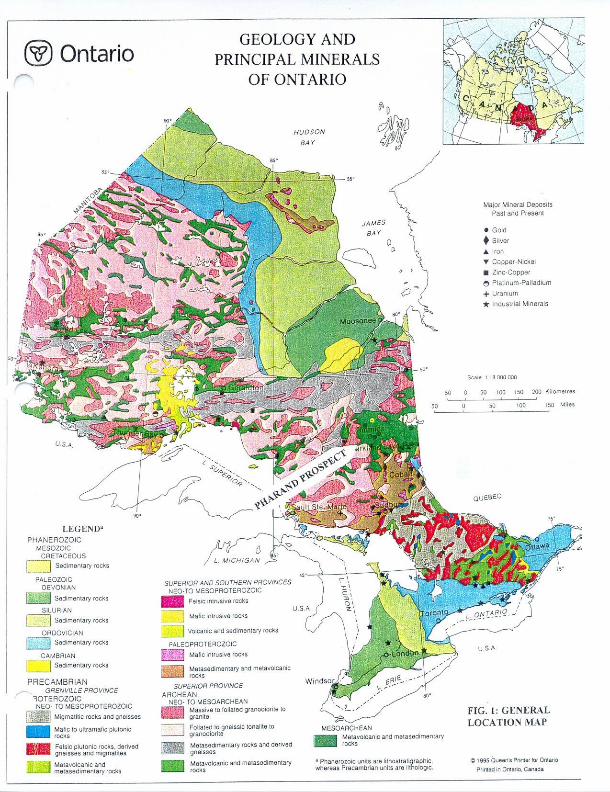
NEO- TO MESOAHCHEANMassive to (olialsd granofliorite tc FIG. 1: GENERAL
LOCATION MAPFoliated !o gneissic tonalite to
MeiasBdimenlarv rooks and d
1 Phanaroioic u nits are l ithostratigraphic wtiersas Pracambrian units are liiholoaic
Malavolcanicand melasaaimantary
LEGEND"PHANEROZOIC
MESOZOIC __CRETACEOUS
! Sedimentary rocks
Sadimemary rocks
___SILURIAN
.J Sa dim en l a ry rocks
ORDOVICIAN i-Jp^' J;-;;| Sedimenlary rocks
__ CAMBRIAN
j Sedimenlary rocks
PRECAMBRIANGRENVILLE PROVINCE
1OTERO2OIC NEO- TO MESOPROTEROZOIC
Felsic plutonic rocks, derived gneisses and migmalilas

42A04NW2002 2.18793 PHARAND 010C
TABLE OF CONTENTS
Introduction. ...,........................................ ...........................................,lProperty, Location, and Access................................................................., lProperty History. ..................................................................................AGeology and Economic Geology................................................................. lDiscussion of the 1997 Work Program.........,............................................... .2Conclusions and Recommendations............................................................ .4Bibliography Certificate
FIGURES
Figure l: General Location MapFigure 2; Township Reference MapFigure 3: Claim Map (Back Folder)Figure 4: O.G.S. Preliminary Occurrence Map P1517Figure 5: O.G. S. Geophysical Map 81379Figure 6: Prospecting MapFigure 7: VLF-EM MapFigure 8: Magnetic ProfilesFigure 9: Plan Map for Drill Hole Location and Mag Profile LocationFigurelO: Section for Drill Hole F3
APPEND1CIES
Appendix l: Sample DescriptionsAppendix 2: Assay SheetsAppendix 3: VLF-EM Specifications and Magnetometer SpecificationsAppendix 4: Diary for Field Days Worked
PART 2
Diamond Drill Logs
— -- -.-.
. . 'X.-1^
v
\ s1 r j )
V f...... ...... x ..-^ v-.~T ~i*-" \ t
\ c / - - "^r ~
/i7
t'Hlr - t— j-
{PHARAND-*'- J
f'"- -L
"^~;',--^^: -.
r"
CHILDERHOSE^; -: "L'
v
i .—-^tc - "\-
t/t* e
INTRODUCTION
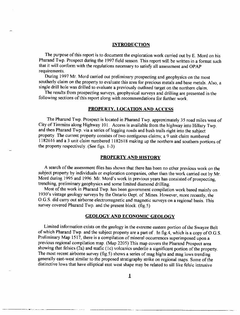
The purpose of this report is to document the exploration work carried out by E. Mord on his Pharand Twp. Prospect during the 1997 field season. This report will be written in a format such that it will conform with the regulations necessary to satisfy all assessment and OPAP requirements.
During 1997 Mr. Mord carried out preliminary prospecting and geophysics on the most southerly claim on the property to evaluate this area for precious metals and base metals. Also, a single drill hole was drilled to evaluate a previously outlined target on the northern claim.
The results from prospecting surveys, geophysical surveys and drilling are presented in the following sections of this report along with recommendations for further work.
PROPERTY, LOCATION AND ACCESS
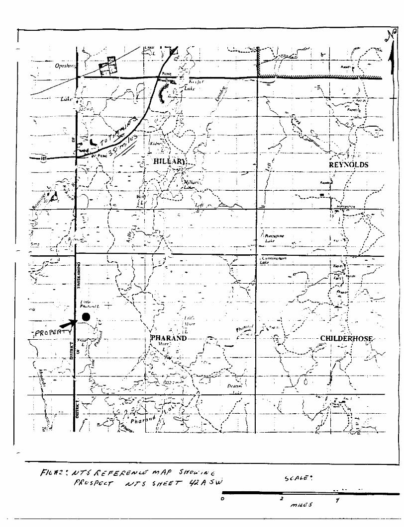
The Pharand Twp. Prospect is located in Pharand Twp. approximately 35 road miles west of City of Timmins along Highway 101. Access is available from the highway into Hillary Twp. and then Pharand Twp. via a series of logging roads and bush trails right into the subject property, The current property consists of two contiguous claims; a 9 unit claim numbered 1182616 and a 3 unit claim numbered 1182618 making up the northern and southern portions of the property respectively. (See figs. 1-3)
PROPERTY AND HISTORY
A search of the assessment files has shown that there has been no other previous work on the subject property by individuals or exploration companies, other than the work carried out by Mr. Mord during 1995 and 1996. Mr. Mord's work in previous years has consisted of prospecting, trenching, preliminary geophysics and some limited diamond drilling.
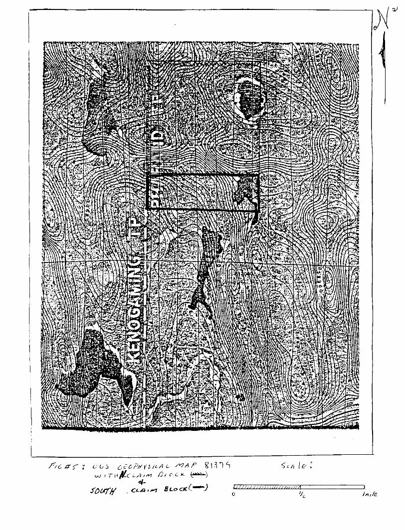
Most of the work in Pharand Twp. has been government compilation work based mainly on 1930's vintage geology surveys by the Ontario Dept. of Mines. However, more recently, the O.G.S. did carry out airborne electromagnetic and magnetic surveys on a regional basis. This survey covered Pharand Twp. and the present block, (fig. 5)
GEOLOGY AND ECONOMIC GEOLOGY
Limited information exists on the geology in the extreme eastern portion of the Swayze Belt of which Pharand Twp. and the subject property are apart of. In fig.4, which is a copy of O.G.S. Preliminary Map 1517, there is a compilation of mineral occurrences superimposed upon a previous regional compilation map. (Map 2205) This map covers the Pharand Prospect area showing that felsics (2a) and mafic (le) volcanics underlie a significant portion of the property. The most recent airborne survey (fig.5) shows a series of mag highs and mag lows trending generally east-west similar to the proposed stratigraphy strike on regional maps. Some of the distinctive lows that have elliptical east west shape may be related to sill like felsic intrusive
l
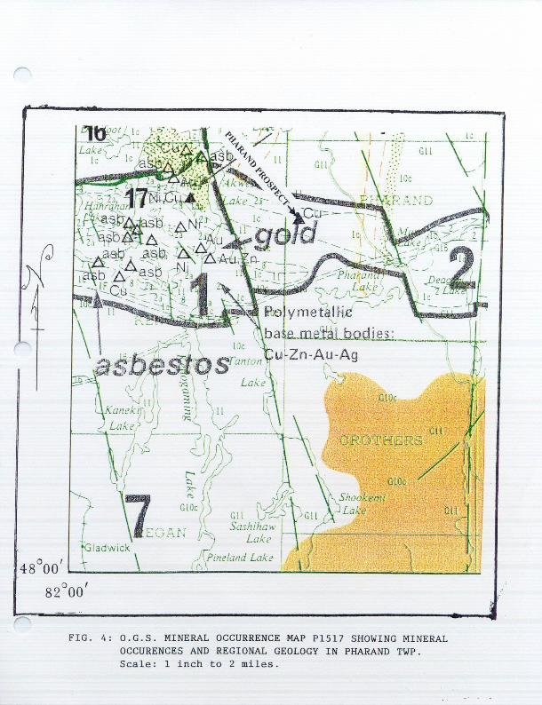
FIG. 4: O.G.S. MINERAL OCCURRENCE MAP P1517 SHOVING MINERAL OGCURENGES AND REGIONAL GEOLOGY IN PHARAND TWP. Scale: l inch to 2 miles.
ft t-c-1-K.e
'4
bodies which were observed on other portions of the property by the author on a much smaller scale.
On a more regional scale, over the past few years the eastern portion of the Swayze Greenstone Belt and the western portion of the Abitibi Greenstone Belt have seen intense gold exploration activity as a result of new discoveries and a reevaluation of old deposits. In the eastern part of the Swayze, which many geologists believe is an extension of the Abitibi Belt, there was extensive exploration carried out in Penhorwood, Sewell and Kenogaming Twps by Marshall Minerals, Battle Mountain Gold, and East Main Resources respectively. These projects lie just west of the Pharand Twp. Prospect within similar lithology. Large scale gold exploration programs were also carried out about 15 miles NE of Pharand in the western Abitibi with a new discoveries by Band Ore Rees, and Holmer Gold Mines.
The Pharand Prospect is underlain by felsic and mafic volcanic sequences similar to that hosting known go!d mineralization on the Battle Mountain and East Main prospects to the west. The sheared volcanics on the subject property have been intruded by altered feldspar porphyritic intrusives, and in many instances both the volcanics and the porphyritic intrusives are well mineralized with pyrite. This environment is a favorable environment for gold mineralization. To date drilling and prospecting on the subject property have shown that there is excellent structure, and mineralization (sulphides) associated with rock types that are known to host gold deposits. However, to date only weakly anomalous gold values have been detected from prospecting and drilling. Work to date on the subject property and surrounding lands has been extremely limited and more work is necessary to properly evaluate the subject property and surrounding land for gold.
The subject property also contains a series of large ultramafic to mafic intrusive bodies. These intrusives on surface and in drill core are well mineralized with pyrite and show that there is some anomalous platinum and palladium values associated with them. These intrusives may have potential for Cu-Ni sulphide mineralization as well. Once again only limited work has been carried out on these intrusives and it is difficult to assess the real potential of these ultramafic bodies without further work.
PISSCUSSION OF THE 1997 WORK PROGRAM
Prospecting Survey
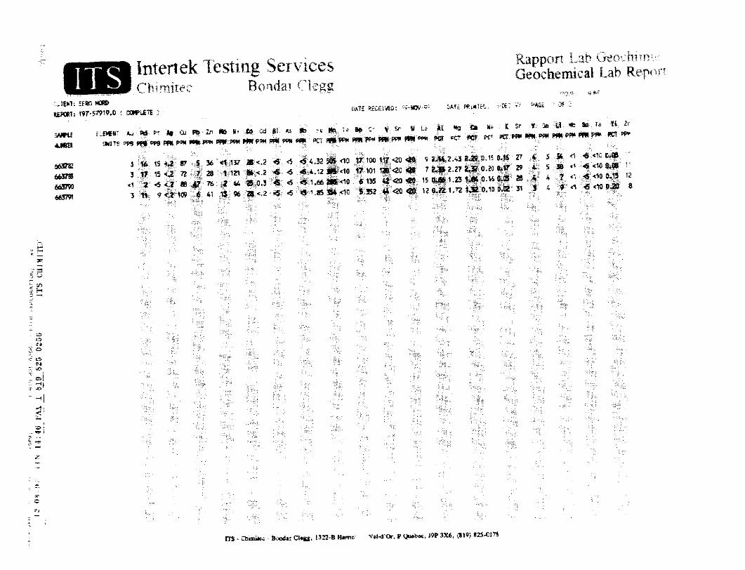
Upon completion of the control grid and VLF survey a prospecting program was carried out over the entire grid established on claiml 182618. (fig.3*fe6) Samples collected suggested the geology on this southern claim was similar to that found on the north claim. Compositionally samples consisted of mafic volcanics, possibly one felsic volcanic, a number of ultramafic to mafic intrusives and a few felsic intrusives. The felsic intrusives were thought to be diorite.(Appendix l)
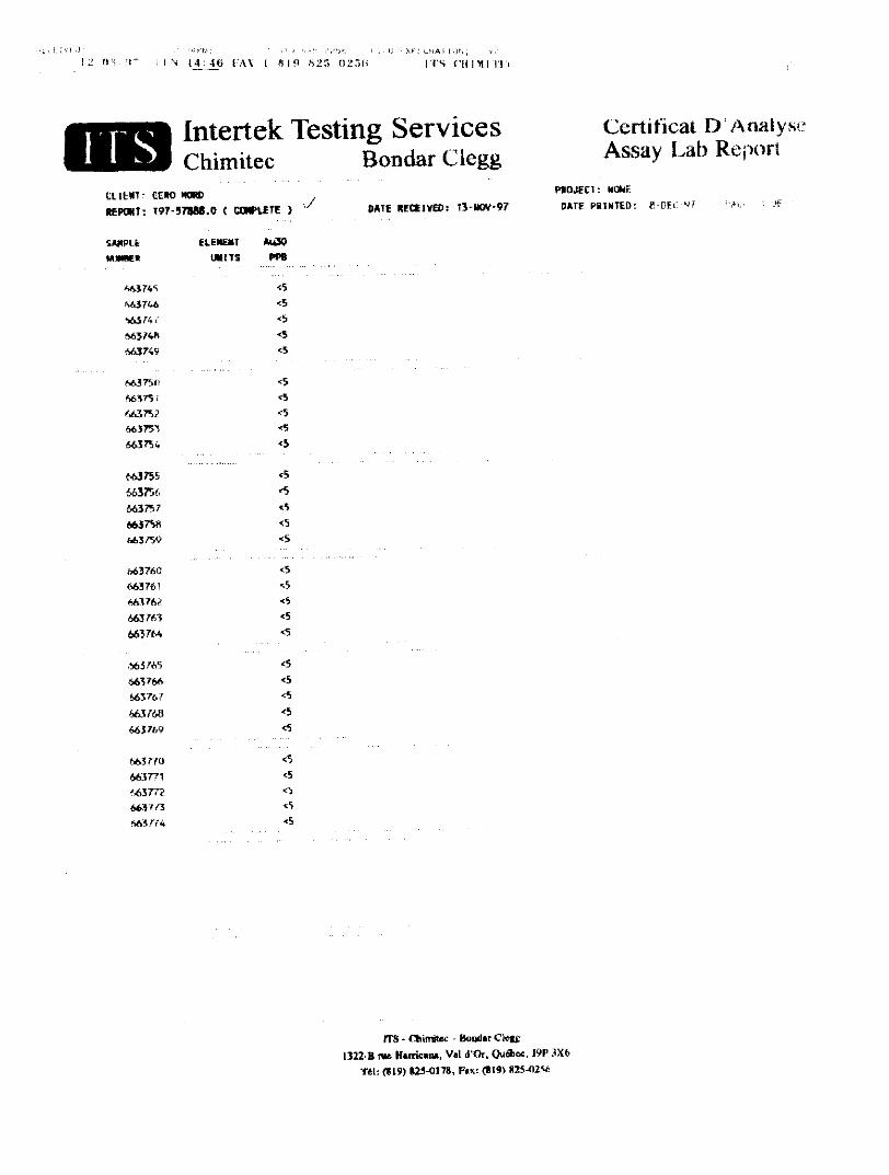
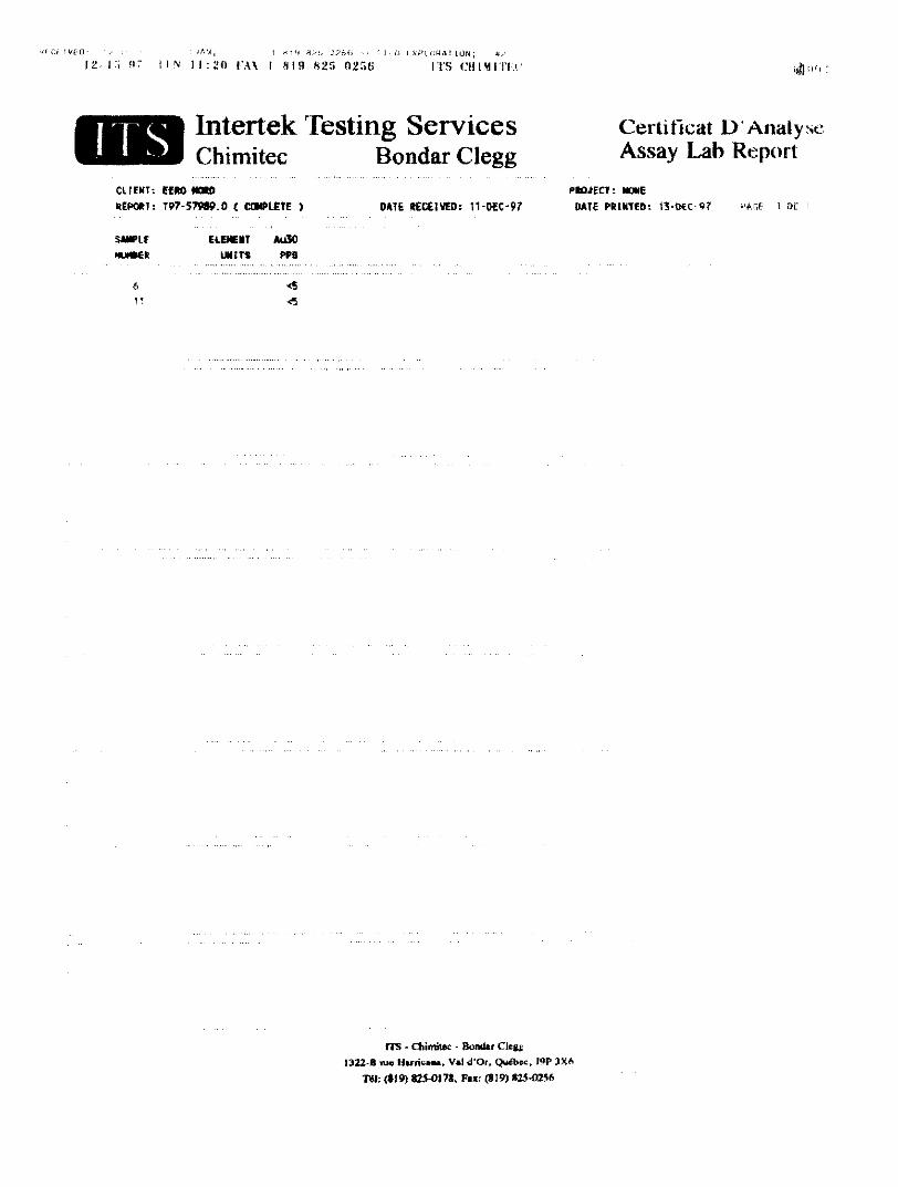
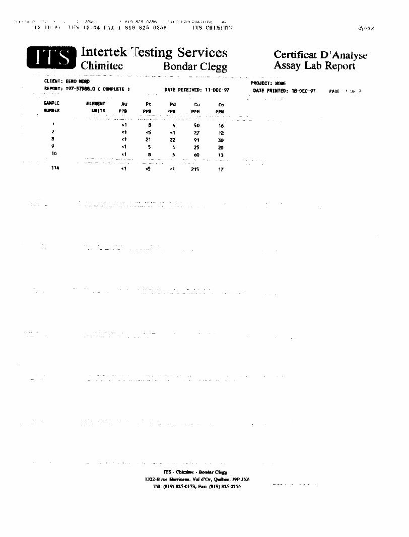
A total of 15 samples were collected during this survey. A total of 8 samples were assayed for various elements. All of the more interesting ultramafic to mafic intrusive samples were assayed for Pt and Pd in light of the anomalous results found in previous surface sampling and drilling in the northern part of the property. There was limited exposure on claim 1182618 and no outcrop was found on the axis of the VLF anomalies. Thus the cause of the VLF anomalies could not be determined from prospecting.

The best results from the prospecting grab samples were obtained from a single sample, sample 8 which contained elevated Pt (21ppb), Pd (22ppb) and Co (30ppm) values. This sample is located a short distance south of a significant VLF anomaly designated Z
Geophysical Surveying
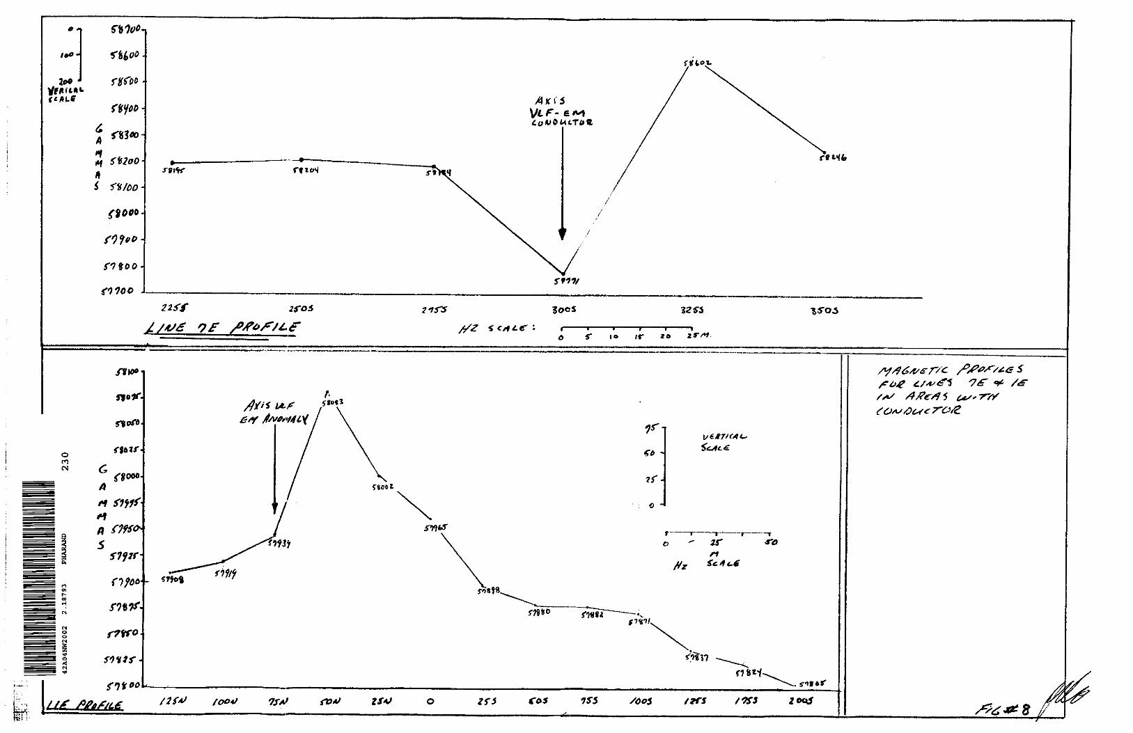
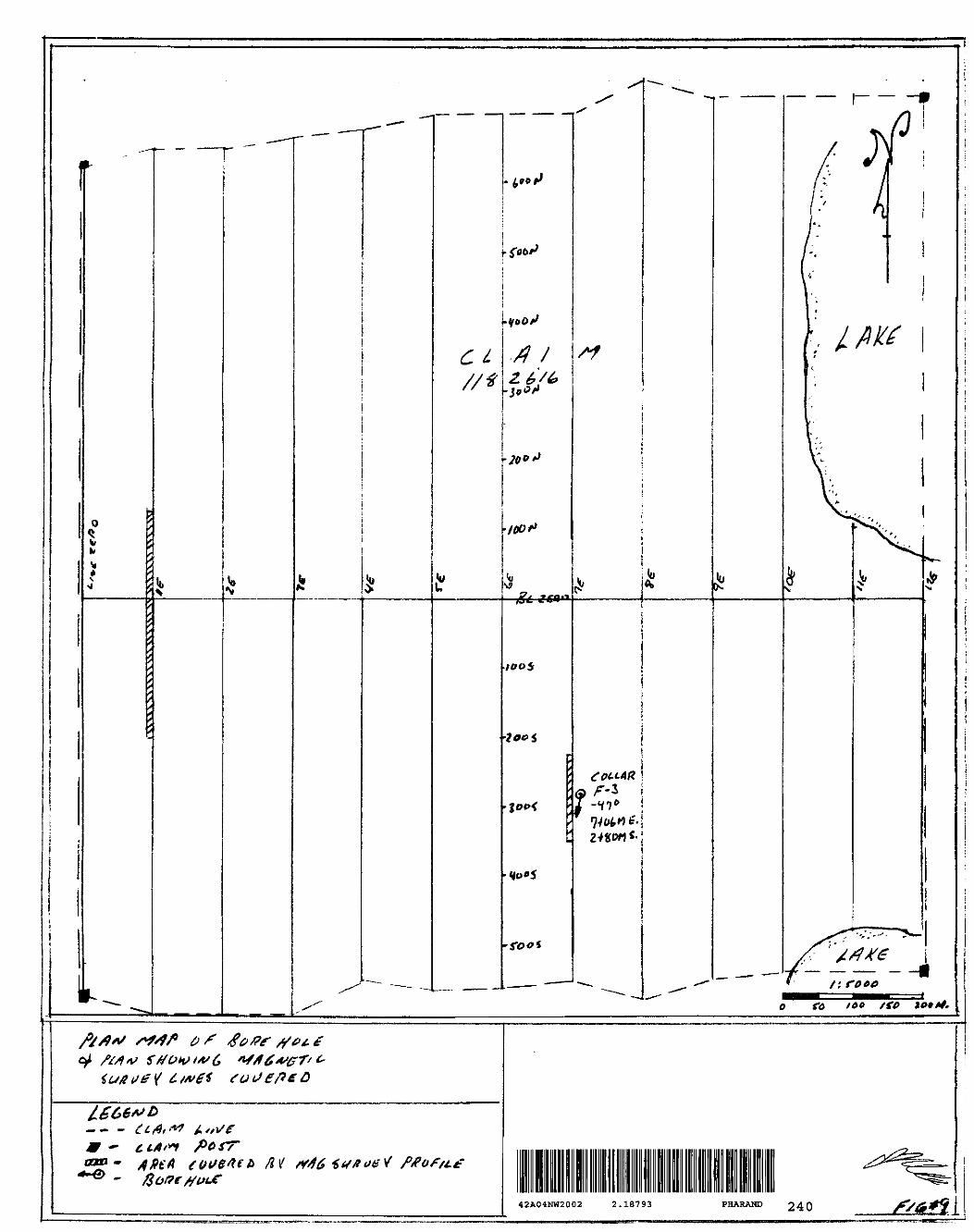
Geophysical survey work on the subject property consisted of a 6.6 km VLF-EM survey over approximately 8007o of the southern claim. Also, two short magnetic profiles on portions of lines IE and IE on the northern claim were completed in the vicinity of previously outlined VLF-EM anomalies.
The magnetic profiles and there locations are shown in figures 8 &9. The profile on line IE covers the target area recently tested by drill hole F3. The profile shows that there is a magnetic low that was coincident with a VLF-EM anomaly. The drill hole intersected a major fault where the magnetic low and VLF-EM anomaly were present, the geophysical response is typical of the structure intersected.
The second magnetic profile shows that a VLF-EM anomaly is on a magnetic high, magnetic low contact. The profile suggests that the VLF and magnetic anomaly have a south dip. The VLF-EM anomaly is likely a legitimate target and further evaluation of this target should be considered.
On the southern claim five VLF-EM anomalies were detected, (fig.7) The most significant anomalies appear to be Z and Y. The author suspects that these anomalies, which both have a NW strike, are the same anomaly that has been faulted. In both anomalies there is a strong in phase response, but the quadrature tends to follow the in phase response to some extent suggesting there is some contribution by conductive overburden to these responses. Anomaly Y becomes much weaker to the SE.
Anomaly W is a short single line anomaly that is very weak, this anomaly is likely a conductive overburden response.
Anomalies U and V trend in a west, northwesterly direction. They both have a limited strike length and the in phase response from these anomalies is weak to moderate. In both cases the quadrature follows the in phase. It is difficult to say if these two anomalies represent a bedrock response, this author suspects that these anomalies are likely due to conductive overburden. However, a more definitive geophysical survey such as induced polarization would be necessary to determine this more accurately.
Diamond Drilling Program
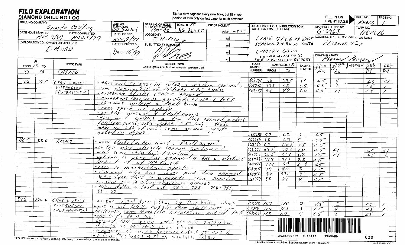
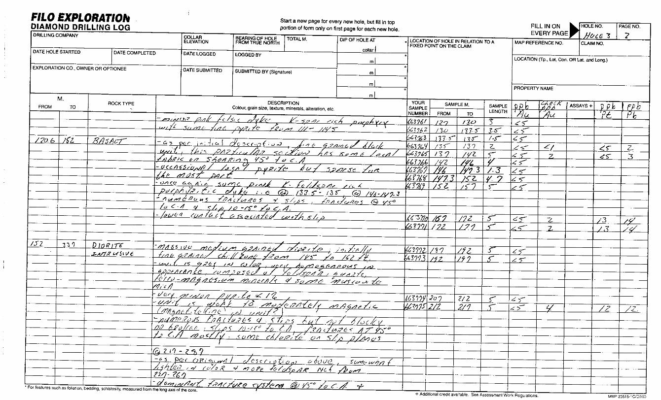
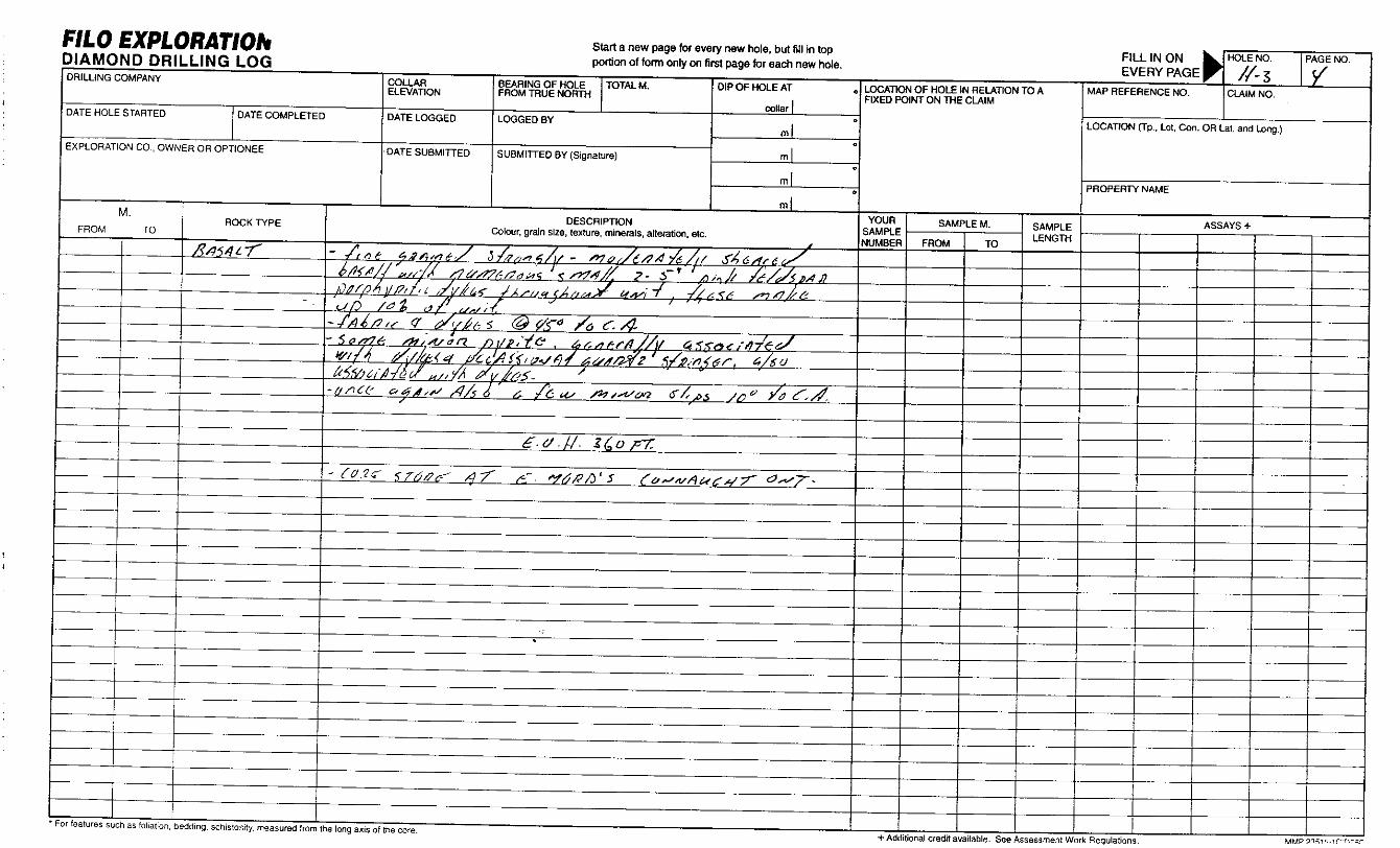
The diamond drill program on the subject property consisted of a single drill hole on claim 1182616 to test a VLF-EM anomaly and a coincident magnetic low. The hole intersected mafic volcanics and a diorite intrusive. A fairly large fault zone was intersected at 46.5 to 104 ft. This zone is likely the cause of the VLF anomaly. Numerous samples from this hole were analyzed for gold. For the most part gold values were not significant, the highest gold assay was 29 ppb in the unit designated diorite. A number of samples within this diorite unit were sampled for

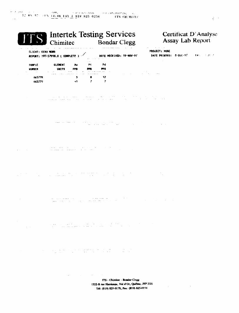
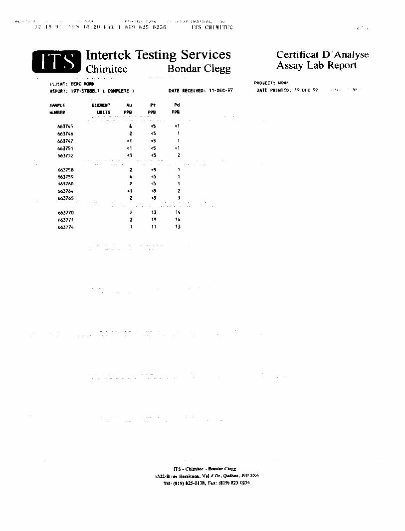
platinum and palladium as well, after two or three initial samples showed weakly anomalous values in Pt and Pd in the order of 15 ppb Pt and Pd. The best Pt and Pd values from this hole were 15 and 17 ppb respectively from sample 66378. Backround anomalous values of approximately 15 ppb Pt and Pd were typical of the low anomalous values found in ultramafic intrusive units in drill holes FI and F2 a few hundred metres west of hole F3. The anomalous backround values, in what appears to be a diorite unit is somewhat surprising as one would expect Pt and Pd values in a diorite to be extremely low or non existent. This unit may have been incorrectly identified, however from a visual examination it does not appear to have enough mafic minerals to suggest this is an ultramafic intrusive.
Conclusions and Recommendation
All of the work to date on the subject property, including the most recent OPAP, has shown that this property contains significant anomalous Pt and Pd values in drill core and numerous surface samples. This mineralization appears to be associated with ultramafic to mafic intrusives that may or may not be associated with substantial sulphide mineralization, however the better samples to date have been associated with pyrite mineralization. Further work is necessary to determine if this property hosts any significant concentrations of Pt, Pd and associated minerals such as Co, Ni and Cu.
The following recommendations should be considered for this prospect:
1) Carry out a soil geochem program over select portions of the property, where there are known but unexplained geophysical anomalies, or known lithogeochem anomalies in areas with limited exposure. Soil samples should be assayed for Pt, Pd, Cu, Ni, and Co
2) A budget should be set aside to assay portions of holes FI to F3 that have not been assayed. Samples should be consistently assayed for Pt, Pd, Cu, Ni, Co.
3) A few magnetic profiles should be run over any known electromagnetic anomalies and any knew geochem anomalies developed from soil sampling or iuture prospecting.
4) Upon completion of the work above, the database for this project should be reviewed to determine if any future work is warranted.

BIBLIOGRAPHY
Ontario Geological Survey Map 1517 and Geophysical Map 81379
Assessment File reports on the Pharand Twp Property by Filo
CERTIFICATE
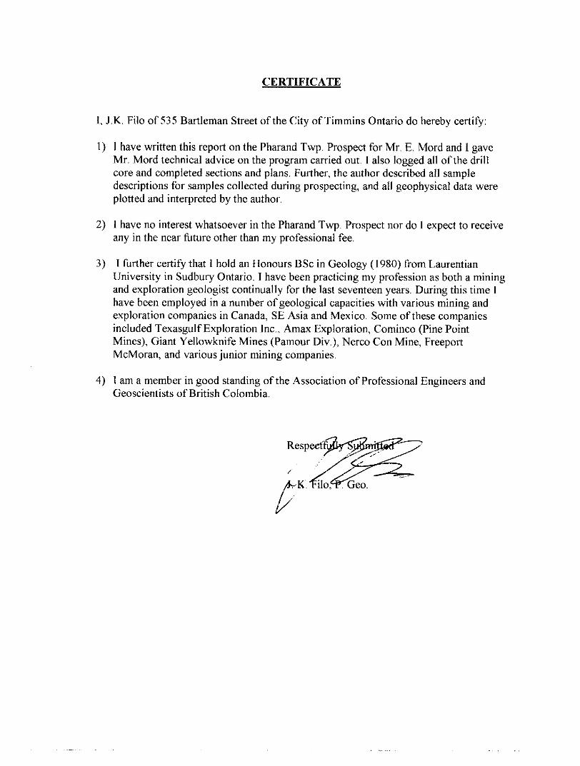
l, J.K.. Filo of 535 Bartleman Street of the City of Timmins Ontario do hereby certify:
1) I have written this report on the Pharand Twp. Prospect for Mr. E. Mord and l gave Mr. Mord technical advice on the program carried out. I also logged all of the drill core and completed sections and plans. Further, the author described all sample descriptions for samples collected during prospecting, and all geophysical data were plotted and interpreted by the author.
2) l have no interest whatsoever in the Pharand Twp. Prospect nor do I expect to receive any in the near future other than my professional fee.
3) I further certify that I hold an Honours BSc in Geology (1980) from LaurentianUniversity in Sudbury Ontario. T have been practicing my profession as both a mining and exploration geologist continually for the last seventeen years. Daring this time I have been employed in a number of geological capacities with various mining and exploration companies in Canada, SE Asia and Mexico. Some of these companies included Texasgulf Exploration Inc., Amax Exploration, Cominco (Pine Point Mines), Giant Yellowknife Mines (Pamour Div.), Nerco Con Mine, Freeport McMoran, and various junior mining companies.
4) I am a member in good standing of the Association of Professional Engineers and Geoscientists of British Colombia.

APPENDIX 1; SAMPLE DESCRIPTIONS

SAMPLE DESCRIPTION
Sample 1 : This appears to a coarse grained mafic to ultramafic intrusive unit that is black in color on the fresh surface, the unit also has some fine pyrite in it, possibly Q.5%. The weathered surface of this unit is a pinkish white suggesting there may be some feldspar. Sample is non magnetic. (Assay Au, Pt, Pd, Co, Cu)
Sample 2 :This sample is a strongly sheared micaceous mafic volcanic that is black in color on the fresh surface there is some brown gossan. (Assay Au, Pt, Pd, Co, Cu)
Sample 3 :This sample is a medium grained grey diorite intrusive with no significant mineralization.
Sample 3A: This sample is a black strongly sheared mafic volcanic with no significant mineralization.
Sample 4: This sample is as per sample 3A
Sample 5 : This sample is a fine grained diorite intrusive rock that is fine to medium grained, it contains no significant mineralization. The sample also contained some quartz veining.
Sample 6: This sample is a very silicious fine grained volcanic, possibly felsic in composition. It has a bleached to tan colored weathered surface. (Assay for Au)
Sample 6A: This sample is a black very fine grained sheared mafic volcanic, no significant sulphides noted.
Sample 7 : This sample is as per sample 3A.
Sample 8: Medium grained metamorphosed mafic volcanic or ultramafic to mafic intrusive that is greenish black in color with a gossanous weathered surface. A small amount of pyrite noted, less than G.5%. (Assay for Au, Pt, Pd, Co, Cu)
Sample 9: This sample is as per sample l but no significant mineralization was noted. (Assay for Au, Pt, Pd, Co, Cu)
Sample 10: This sample is a medium to coarse grained black mafic to ultramafic intrusive rock with some fine pyrite. The sample contains a very unusual green mineral in a small section of the sample; there are about 20-30 specks of this non metallic mineral. (Assay for Au, Pt, Pd, Co, Cu)
Sample 11: This sample is a medium grained intrusive rock, possibly a diorite, it has a grey matrix with pink feldspar phenocrysts. (Assay for Au)

Sample HA: This sample is a black coarse grained intrusive that is ultramafic or mafic in composition. No significant mineralization is noted, except for some minor chalcopyrite associated with a clot of quartz carbonate. (Assay Au, Pt, Pd, Co, Cu)
Sample 12: This sample is a black strongly sheared fined grained mafic volcanic with no significant mineralization.

APPENDIX 2 :ASSAY S HEETS
;4(j I,V\; UtlAI |,)f, . 'J
ITS mi Hi re
ITS Intertek Testing ServicesChimitec Bondar Clegg
CLIENT: ECHO MORB
Rf POUT: 1 97-57888.0 ( COMPUTE )
SWPtfc AuSO UHtTS PM
MJ7U,
663/49
665751
663755
6637M 663/^7 66J7SH 6637SV
&6376C 66376' M376? A63761S 663764
•5*5
<5
KATE RCOEIVCOt 13-HOV-97
Certificat D 'Analyst Assay Lab Report
PVQJtECl : OfcTE PRINTED: S D E i" '^i •w.. : *
46^766 66576 f
663/63 66 J 769
66S770 661771 A6377?
<5
-S
ITS - dittnttec - Boudar Cloff
1322 B me Hurimik, Val d'Or. Qu*fie, J9P -1X6
T61: (819)

OS 'j: i f N 14:48 \ \\\ l HI!) 825 025B ITS C1ILMITH
ITS Intertek Testing ServicesChimilec Bondar Clegg
CLIENT i EEWREPWT: T9r 57920.0 ( CCWH.ETE J J
SAMPLE
WMBEtl
ELEMENT
UNITS PW
DATE RKKIVTO: 19-MOV-97
Certiticat D 'Analyse Assay Lab Report
PROJECT i MOM-
DATE PRINTED: a DEC -9f
6637/6 665777"
663760
663781
663784
663785
A63786
M3787
663T86
663789
6637V?
663791
6637W
663/Vb
663796
29
6
O <5
ITS - Chimilw - (322-B nw Hanicuu, Vtt d'Or. Quebec, np 3Xfi
Tfl; (819) 825-017B. FM: (819} 129-0256
l:1 ns 'ir IN i 4; w I-A\ i ft2f. 02iili ITS CH1MITI.!
ITS Intertek Testing Services Ceruticat D AnalyseChimitec Bondar Clegg Ass*y Lab Report
CLIENT: EEftQ WRD PROJECT: KONE
REPORT: T97-57VW.O ( COUPLET^ ) ^ DATE BEttlVED: I9-WW-97 DATE PftlKTED: 8-Dfet:-97 's ;"
SWPLE ELEKNT Au Pt Pd
WUKSEB UK ITS PPI PM1 PPI
66377R 5 8 12
643779 ^ 77
Bofldir Ckut I32J-B m* l Umwuu. Vtl d'Or, QnAwo, J9P 3X6
Til: (*19) Ji5-0178, Ptxi (819) 825*256
ITSKENM:
66373266378
663790643791
Intertek Testing ServicesChimitec Bondai Clegg
MORD
Au M- * *t Cu -S&-2T MO Wf. tt Cd iC Ri 8b re g^.. T?
ops ffjfjrsfS PW PBM W*.:pPN PW-PW WPTfW fWI WU (W'" PCT ffjt'W*
3.5? 15*1 ^ -53 -ft 9
87 -5 : 36 72 -:. 28
Rapport Lab Geochim Geochemical Lab Rep*
V : ST V U Jtt *g CI *ft t Sr t- -3ft
PK;PPK f***** ^F Ptr *Cf: PC* WTW PPM Pt*
. 15 8.16 Z? 5 S*
T 2^-;2.27 4^0.20 MT 29 ..^ S ^15 CW1.23 Vu 28 ^ 4 .^,
.1Q8^^ 31 "J' 4 f
WTT
ITS , 1312-B H*mc' I9P 3X6,
l!' '.tt \(-N l*i:2fl l AX l fill! 825 0236Xl'i (IriAl SON, H .'
ITS C
ITS Intertek Testing ServicesChimitec Bondar Clegg
CLJCttT: E E RG
REPORT: 797-57888,1 ( CGMPtETE
HUMBFB
E L CTtN T
UNITS
Au PPB
663741663746663747663751663752
Certificat D AnaJy.se Assay Lab Report
Pt PPfl
<5
<5
<5
DATE RECEIVED: 1 1-DEC-97
PdPPB
PSOJECT: NOKt
DATE PRimeO: 1 9 Df.C
6637^8
663759
663764663765
663770663771663774
^
^
13
11
1 l123
141413
ITS - ChimiHc - Boodar Ctegy 1312-B nK Hftfiic.o*, Vd d'Or, Qvib**,
Tfl: (819)*25-OI7Ht F*JI; (819) 525-

i;:' --t" UN Hi:4B FAX i KID ^2.1 0230 ITS O
ITS Intertek Testing Services Chimitec Bondar Clegg
CMFUT: EIRO NOBD
REPORT; 797-57920.1 ( CCNPLETt
SAHPLENUMBER
ELEMENT UNITS
Au PPB
66377?
663776
6637BO
663744
665785463788665789
66379J
443
<^
Certificat D AnalyseAssay Lab Report
PtP(*B
U 13
15131t12
DATE RECEIVED: 1I-BCC-97
PdPPB
PROJECT: HCHe
DATE PRINTED: 22-DEC-97
16tt33
16 15 H 15
5
ITS - ChimlUic - fkndar Clegg 1322-B me HunciM. Vtl d'Or, QU&CL. J9P 3X0
Til: (119) 825-0178, Fax:
J AM, l M t f) H ^:, 0 2fcfi '-J. i) t XPU-JKA! [ON; B/
IN M: SO IA\ l 819 825 0256 ITS CH l H M!.('
l T S Intertek Testing Services Chimitec Bondar Clegg
CLIENT: CfftO HQtOREPORT: 197 57989.0 ( CONPiCTE MTG RECEIVED: 1 1-DEC-97
SMPLF
NUHfeCR
ELBCHT Au50 UtttTS fPB
Certificat D Analyse Assay Lab Report
PROJECT: NONE DATE PRINTEDs 1 3-DfC 9? if, S DC
ITS - Cliiiratec - Bondtr Ckgi 1322 8 nw HwricMi, V*l d'Of. Quebec,
T(l: (*19) 825-017*, Fix. (819) 93540*6
T L- '' ' , -' ' '.l^M; ' t}l9 ^25 OPSfi . i M O f- 12 M l M/ \KN 1 2:04 KA X I H19 825 0250 ITS C
ITS Intertek Testing ServicesChimitec Bondar Clegg
CtlENT; EEROMOttWPORT: T97'579tt.O ( COMPLETE D PATE RECEIVED: 11-DEC 97
Certificat D 'Analyse Assay Lab Report
PROJECT: NOME DATE WIMTED: lfl~MC-9r MGf.
SANPU
MUWER
1
Z
a9
ia
11*
CLEMENT UNITS
AU PPI
Ptm
21 5 B
CdPPB
2245
Cu
PPH
SOz?
60
215
Co PPH
16 12 SO M 13
ITS - CbimfeK - Bondtr Clegg1322-B nw H*mc*M. V*I d'Or. Quebec, 19P 3X6
Til: (819) 124-0178, Pu; (*I9) 825-4856

APPENDIX 3:INSTRUMENT SPECIFICATIONS
Page l
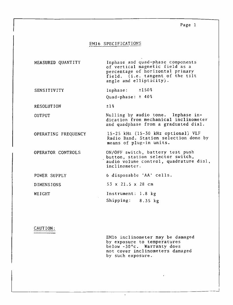
EM16 SPECIFICATIONS
MEASURED QUANTITY
SENSITIVITY
RESOLUTION
OUTPUT
OPERATING FREQUENCY
OPERATOR CONTROLS
POWER SUPPLY
DIMENSIONS
WEIGHT
Inphase and quad-phase components of vertical magnetic field as a percentage of horizontal primary field. (i.e. tangent of the tilt angle and ellipticity).
Inphase: 1504
Quad-phase: 404
14
Nulling by audio tone. Inphase in dication from mechanical inclinometer and quadphase from a graduated dial.
15-25 kHz (15-30 kHz optional) VLFRadio Band. Station selection done bymeans of plug-in units.
ON/OFF switch, battery test push button, station selector switch, audio volume control, quadrature dial, inclinometer.
6 disposable 'AA' cells.
53 x 21.5 x 28 cm
Instrument: 1.8 kg
Shipping: 8.35 kg
CAUTION:
EMlb inclinometer may be damaged by exposure to temperatures below -30 0 c. Warranty does not cover inclinometers damaged by such exposure.

QUADRATURE. CONTROLINCLINOMETER
FIG. l EM 16EARPHONE, JACK
CASE
HANDLE-VER^
HORIZONTAL
VOLUME CONTROL
STATION SELECTOR
Conductor Behind

Page 19
FIELD PROCEDURE
Orientation St Taking a Reading
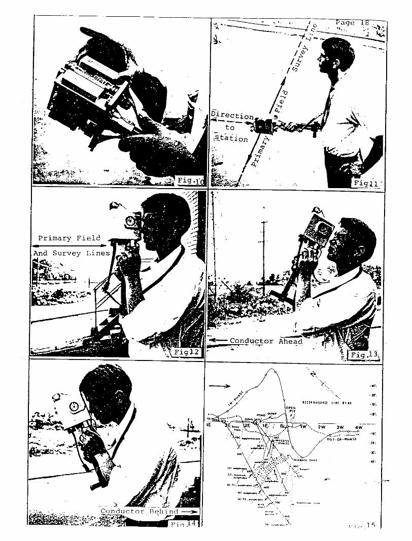
The direction of the survey lines should be selected approxi mately along the lines of the primary magnetic field, at right angles to the direction to the station being used. Before starting the survey, the instrument can be used to orient one self in that respect. By turning the instrument sideways, the signal is minimum when the instrument is pointing towards the station, thus indicating that the magnetic field is at right angles to the receiving coil inside the handle.(Fig.11).
To take a reading, first orient the reference coil (in the lower end of the handle) along the magnetic lines.(Fig.12) Swing the instrument back and forth for minimum sound intensity in the speaker. Use the volume control to set the sound level for comfortable listening. Then use your left hand to adjust the quadrature component dial on the front left corner of the instrument to further minimize the sound. After finding the minimum signal strength on both adjustments, read the inclino meter by looking into the small lens. Also, mark down the quadrature reading.
While travelling to the next location you can, if you wish, keep the instrument in operating position. If fast changes in the readings occur, you might take extra stations to pinpoint accurately the details of anomaly.
The dials inside the inclinometer are calibrated in positiveand negative percentages. If the instrument is facing 180O from the original direction of travel, the polarities of the readings will be reversed. Therefore, in the same area take the readings always facing in the same direction even when travelling in opposite way along the lines.
The lower end of the handle, will as a rule, point towards the conductor. (Figs.13 6 14) The instrument is so calibrated that when approaching the conductor, the angles are positive in the in-phase component. Turn always in the same direction for readings and mark all this on your notes, maps, etc.
THE INCLINOMETER DIALS
The right-hand scale is the in-phase percentagefie. Hs/Hp as a percentage) . This percentage is in fact the tangent of the dip angle. To compute the dip angle simply take the arc tangent of the percentage reading divided by 100. See the conversion graph on the following page.
The left-hand scale is the secant of the slope of the ground surface. You can use it to "calculate" your distance *o the .. next station along the slope of the terrain.

B X
S T
O T
HE
CE
NT
IME
TE
R
46
162O
IB
X 24
C
M.
•IB
I i*
u t
t.
KC
UF
rCL
ft
ES
SE
R
CO
.
Page 21
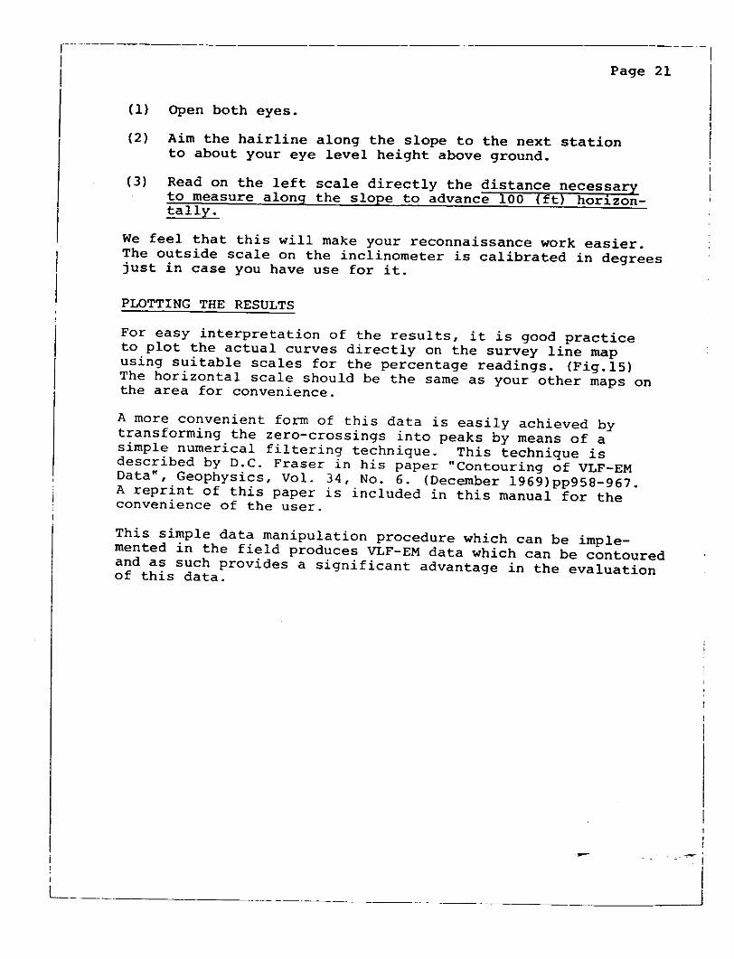
(1) Open both eyes.
(2) Aim the hairline along the slope to the next station to about your eye level height above ground.
(3) Read on the left scale directly the distance necessary to measure along the slope to advance 100 (ft) horizon tally.
We feel that this will make your reconnaissance work easier. The outside scale on the inclinometer is calibrated in degrees just in case you have use for it.
PLOTTING THE RESULTS
For easy interpretation of the results, it is good practice to plot the actual curves directly on the survey line map using suitable scales for the percentage readings. (Fig.15) The horizontal scale should be the same as your other maps on the area for convenience.
A more convenient form of this data is easily achieved by transforming the zero-crossings into peaks by means of a simple numerical filtering technique. This technique is described by D.C. Fraser in his paper "Contouring of VLF-EM Data", Geophysics, Vol. 34, No. 6. (December 1969)pp958-967. A reprint of this paper is included in this manual for the convenience of the user.
This simple data manipulation procedure which can be imple mented in the field produces VLF-EM data which can be contoured and as such provides a significant advantage in the evaluation of this data.

age
INSTRUMENT
MAGNETOMETER f GRADIOMETER
Accuracy:Range:
Gradient Tolerance:Operating
(nput/Output: Power Requirements:
Power Source:
Battery Charger:
Operating Ranges;
Storage temperature: Display:
Dt mentions:
VLFFrequency Range; Parameters Measured:
Resolution: Number of Stations: Storage:
Terrain Slope Range: Sensor Dimensions: Senaor
0.01 nT (gamma), magnetic fteJd and gradient0.2 nT over operating range.20,000 to 120,000 nT.Owl 0,000 n-rVm3 seconds minimum, falter optional. Readings Initiated from keyboard,external trigger, orcarriage return via R5-232-C6 pin weatherproof connector, RS-232C, and (optional) analog output,12 V, 200 mA peak (during polarization), 30 mA standby. 300mA peakin gradiometer mode.Internal 12V, 2.6 Ah Maled lead-acid battery standard, others op-ttonai. An External 12V power source can also be used.Input 1 10 VAC-60 HZ. Optional 110/220 VAC, 5CV60 Hz.Output: dual level charging.temperature: -40 "C to -f 60 *CBattery Voltage: 1 041V minimum to 15V maximum.Humidity* up to 90* relative, nan condensing.-SO-Cto+eS-C
LCD: 240 X 64 pixels, or B K 30 Characters. Built in heater for operation below -20^Console; 223 x 69 x 240mm.Seraor vtafft 4 x 450mm sectionsSensor: 1 70 x 71mm dla.
Console 2,1 kg. Staff 0.3kg, Sensors 1.1 kg each.
15-30.0 kHz..Vertical In-phase and Out-of-phase components as percentage of totalfield.2 components of horizontal field.Absolute amplitude of total field.0.19t.Upo3atatime.Automatic with; time, coordinates; magnetic fiek^padient, slope,field, frequency^ In- and outttf-phase vertical, and bothcomponents for each selected station.O--90^ (entered manuafty).14 x 15 x 9 cm. (5.5 x 6 x 3 inches*.
GEM Systems Inc.
APPENDIX 4:DAILY DIARY
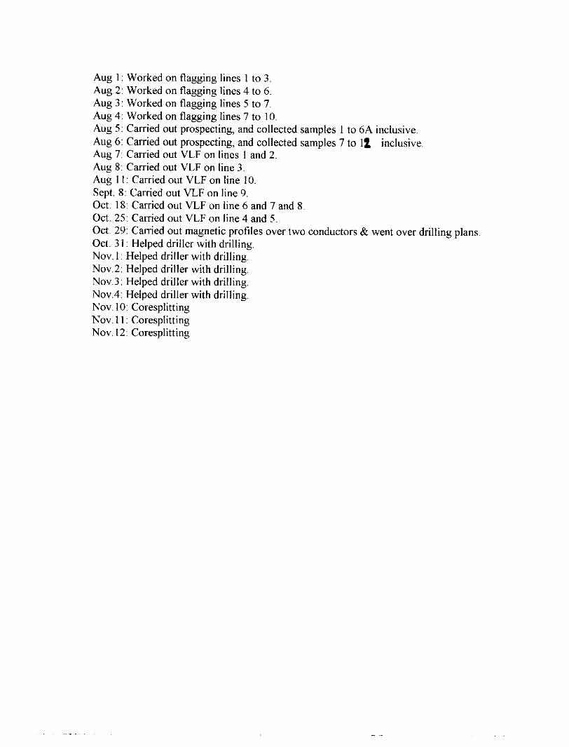
Aug l: Worked on flagging lines l to 3.Aug 2: Worked on flagging lines 4 to 6.Aug 3: Worked on flagging lines 5 to 7.Aug 4: Worked on flagging lines 7 to 10.Aug 5: Carried out prospecting, and collected samples l to 6A inclusive.Aug 6: Carried out prospecting, and collected samples 7 to li inclusive.Aug 7: Carried out VLF on lines l and 2.Aug 8: Carried out VLF on line 3.Aug 11: Carried out VLF on line 10.Sept. 8: Carried out VLF on line 9.Oct. 18: Carried out VLF on line 6 and 7 and 8.Oct. 25: Carried out VLF on line 4 and 5.Oct. 29: Carried out magnetic profiles over two conductors & went over drilling plans.Oct. 31: Helped driller with drilling.Nov. 1: Helped driller with drilling.Nov.2: Helped driller with drilling.Nov.3: Helped driller with drilling.Nov.4: Helped driller with drilling.Nov. 10: CoresplittingNov. 11: CoresplittingNov. 12: Coresplitting
FILODIAMOND DRILLING LOG
Start a new page for every new hole, but fill in top portion of fonn only on first page for each new hole. FI LL 1 N ON
PAGEHOLE NO. PAGE NO.
DRILLING COMPANY
DATE HOLE STARTED DATE COMPLETE
EXPLORATION CO., OWNER OR OPTIONEE
. rfoflD
COLLAR ELEVATION
DATE LOGGED
DATESUBr/ITTED
BEARING OF HOLE FROM TRUE NORTH
TOTAL*
346 FTLOGGED BY
DIP OF HOLE AT
______collar l - y
LOCATION OF HOLE IN RELATION TO A FIXED POINT ON THE CLAIM
~t
MAP REFERENCE NO. CLAIM NO.
LOCATION (Tp., Lot, Con. OR Lat. and Long.)
PROPERTY NAME
Ej ?v y~ j ASSAYS *—— t r' ' ————M.
FROM fi- TOROCK TYPE DESCRIPTION
CokJijr, grain size, texture, minerals, alteration, etc.YOUR
SAMPLE NUMBER
SAMPLE*.
FROM TO
SAMPLE LENGTH ^i.
fip^O
5"L/
^ /'/l^ SLS/ oAv 1 s/ f-s ! / c ^ix 5 5&S
/k c/? e*-/* j " -5
J f f 'f C-K t a/- st r ? /*s.
~l /'-^ 5
TJc/-t o r t*.
s*1 5"r'f 6/attyh, ,*L 6V-*"
fits/? if/CfS e r 2-06 5"i ^ G- f-4/as-?/ fc'e c. T f S* iJl Z-
TV-/ . 3/O f' / 7-7
-s J,? c Di//7 - 9-?- A , -
-*1? vJ/?/?'*? C**/
fcfa* ^ / : st-J/TrC' f,
^ ~ lo- f;-it-
IKS fc-!/ D'O-7 T ptr 't Z h off i-^ li t r t /o 7 //e -•j f 5 nut /d /A //o
s 1^ S, st a //J y?*"le C* f - r K"^6 l///^ x/ /^ ^X ^ C, S f. ir, - x p) r (t f 7 , C-
. b c; c' c?^ ]t: S h ^ xi r i
For features such as foliation, bedding, schistosity measured from the long ax s of Ihe core.di o/lf A 7/ bs i 42A04NW2002 2.18793 PHARAND
-t- Addftional credit available. See Assessment Work Regulations.
020
EXPLORATIONDIAMOND DRILLING LOG
Start a new page for every new hole, but fill in top portion of form only on first page for each new hole. FILLINON
EVERYPAGEw HOLENO.
JJC/&G ~S
PAGE NO.
DRILLING COMPANY
DATE HOLE STARTED DATE COMPLETED
EXPLORATION CO.. OWNER OR OPTIONEE
COLLAR ELEVATION
DATE LOGGED
DATE S UBMITTED
BEARING OF HOLE FROM TRUE NORTH
TOTAL M.
LOGGED BY
SUBMITTED BY (Signature)
DIP OF HOLE AT
collar
m
LOCATION OF HOLE IN RELATION TO A FIXED POINT ON THE CLAIM
MAP REFERENCE NO. CLAIM NO.
LOCATION (Tp., Lot, Con. OR Ut. and Long.)
PROPERTY NAME
M. FROM TO
ROCK TYPE DESCRIPTION Colour, grain size, texture, minerals, alteration, etc.
YOUR SAMPLE NUMBER
SAMPLE M.
FROM TO
SAMPLELENGTH
/ASSAYS -h
Ph5
\9f/-/?/ X^e X&
ill. t-r220, tfL '-f i TT, c. i ^ ^ 77? J/** /J? z. Z-^ZZ j^ m 3- OttSliS/fJsJ/) 7 /j e/* Z d u y ttWtf /-J
wm /22- 7/^- /sS*;/? x?/- x /'t, X" JX2. r"
y O*V X/'A S& -Sf 0 Sf ^
fat-f frfr&cM/Ct/ JLA, z^3.
IT Z12. z^. r. 1.
g . ^^^.7^3'g^ t/ s7?sf s?-sr?/94/? 25* t""
' l/C'2/Z rz 2/1
5"
/j,? 6?a fa t , -r/, j t2z^r^ / J7f" s^ y;
-65
d 1 1? {e
ft'* /a f s#For features such as foliation, bedding, schistosily. measured from the tang axis of the core,4- Additional credit available. See Assessment Work Regulations. WMP23515-1C/D2BO

FILODIAMOND DRILLING LOG
Start a new page for every new hole, but fifl in top portion of form only on first page for each new hole. FILL IN ON
EVERYPAGEHOLE NO- PAGE NO.
DRILLING COMPANY
DATE HOLE STARTED DATE COMPLETED
EXPLORATION CO., OWNER OR OPTIONEE
COLLARELEVATION
DATE LOGGED
DATE SUBMITTED
BEARING OF HOLE FROM TRUE NORTH
TOTAL M.
LOGGED BY
SUBMITTED BY (Signature)
DIP OF HOLE AT
collar
m
LOCATION OF HOLE IN RELATION TO A FIXED POINT ON THE CLAIM
MAP REFERENCE NO. CLAIM NO.
LOCATION (Tp-, Lot, Con. OR Lat. and Long.)
PROPERTY NAME
M. FROM TO
ROCK TYPE DESCRIPTIONColour, grain size, texture, m inerals, alteration, etc.
YOUR SAMPLE NUMBER
SAMPLE M.
FROM TO
SAMPLE LENGTH
pel ppb V±-
/, x? f /t T /t 29/. C/ 'If-, /' /?j /*231
5~S3
2V?77 r j.-S39
5 PC.-? ^T^^Z.
r xr^L 5"
J-3- /,-r-i^ c, 7/3 A)/?, f. rf-
temy SL /r\l t 'f /rt 'te S&&t+sti*
vfifa f.~t Z * 6 y f rt-3 07 JSLs"
32-7 33 r x/.7? 2
3SL fi 7^ /f , 2/X3/r -3x/w S?/ -/btf 3*Z. S
/L /I //?st {Sf6#,s 3571L
s?/For features such as foliation, bedding, schistosity, measured from the long axis of the core.
4- Additional credit available. See Assessment Work Regulations. MMP 23515-10/02^
MLW tAPLUHATIUNDIAMOND DRILLING LOGDRILLING COMPANY
DATE HOLE STARTED DATE COMPLETED
EXPLORATION CO., OWNER OR OPTIONEE
M.
FROM TOROCK TYPE
^5^7^ - J" t. S r s) f
tiff f ft A
COLLAR ELEVATION
DATE LOGGED
DATE SUBMITTED
4^/3"?^^ fc'-/'t*//-// S7&/T,m-i j /^~r — [iff'T'i /7\f#^
Start a new page for every new hole, but fill in top p^L ||*g ON ^. portion of form only on first page for each new hole. EVERY PAGE rBEARING OF HOLE TOTAL M. DIP OF HOLE AT 0 FROM TRUE NORTH
collarLOGGED BY
m0
SUBMITTED BY (Signature) m
mo
mDESCRIPTION
Colour, grain size, texture, minerals, alteration, etc.—- ————— - ———————— ~ ———— 7—f ———— - —————— 4 —————
7ts?e3frt T sv74# ?~ i" T * A**Jt /t/ts/SaJJ}J- 'A /-w t A s,™ J/ t* 'M ~f -/^^ *S s*? rf 'A 6't*t o/* M',-e
~ S/! 4/7, s (7 d/Y^t- ^ ® tfc1* SG f- d-- -5 o /rt 6 sto^sts In f) i/f/fe ^ s /j fi f A Mf G TTo t iA~/^^
Hf(*i4 0/1/^4 {/{.Jd&iU+SflS SZ/SJ/2&2 ^/S;rt46f 6/60fc}fS}6i
~ fJ S* t C#-i6(/ M/s'/A 0*
c* 4 J /s/ /5 Vs 6s s /C xs /tt/f/av f/'xs /ti" /0 f'/f'
g. c/ . /./. l(,o FT,
-(Ol? ^rtitfe' 4 7 t*-~ f6#ft l S fa+ss/Atsfs/T' 0'"7'~
*
LOCATION OF HOLE IN RELATION TO A FIXED POINT ON THE CLAIM
YOUR SAMPLE NUMBER
SAMPLE M.
FROM TO
SAMPLE LENGTH
MAP REFERENCE NO.
HOLE NO.
CLAIM NO.
PAGE NO.yLOCATION (Tp., Lot, Con. OR Lat. and Long.)
PROPERTY NAME
ASSAYS *
' For features such as foliation, bedding, schistosity, measured from the long axis of the core-t- Additional credit available. See Assessment Work Regulations.

Declaration of Assessment Work Performed on Mining Land
Mlnina Act Subsection 66(2) and 66(3), R.S.0.1890
Number {office ut*)
Assessment Files Research Imaging
*cUons 65(2) and 66(3) of the Mining Act. Under section S of the Mining Act. this
it work and correspond wtth the mining land holder. Questions about this collection
nt and Mines. 3rd Floor, 993 Ramsey Lake Road, Sudbury, Ontario, P3E 6B5,
42A04NW2002 2.18793 PHARAND 900
Instnictions: - For work performed on Crown Lands before recording a claim, use form 0240.
- Please type or print in ink.
1. Recorded holder(s) (Attach a list if necessary)
NameM P. (z ' - *4 o a o
Address
ptitu (A dName
Address
Client Number /s? 2S f C^
Telephone Number
Fax Number ^-,
Client Number
Telephone Number
Fax Number
2. Type of work performed: Check OO and report on only ONE of the following groups for this declaration.
Geotechnical: prospecting, surveys, assays and work under section 18 (regs)
rn^Pfiysical: drilling stripping,*i trenching and associated assays
Rehabilitation
Work Type
Dates Wort Performed
/y/A/nc/v p r vifr- ei fi j
From / d'Tf 9^ To -y f
Day | Month | Year Day |
Global Positioning System Data (if available)
iZ 9?Month | Year
Tmvnship/Area Z// S' ~~ "^ * . //^^/7^^xy S ~V J&.
M or G-Plan Numjwr - T
Office Use
Commodity
Total S Value of 4^, Work Claimed f^f ^ /(j
T t /^ ^
NTS Referencet i
Mining Division l^A fau-ftf- o
Resident Geologist .l——- \ .
District j f jfa~w^*y--t3
Please remember to: - obtain a work permit from the Ministry of Natural Resources as required;
- provide proper notice to surface rights holders before starting work;
- complete and attach a Statement of Costs, form 0212;
, i - provide a map showing contiguous mining lands that are linked for assigning work;
- include two copies of your technical report.
3. Person or companies who prepared the technical report (Attach a list if necessary)
Name i S ,
Address ' o /, C1 -./ ^^7" * f
SSV lO/3/^/f /^.. A^ x A-^ " t/'-S*. ~r^J**5 t~4~Sl
Name
Address
Name
Address
Telephone Number ,—i ^ ~r? ~
*/ 0 5 -- S b *T "iSlf^LG G ^
Fax Number
Telephone Number
Fax Number
Telephone Numbe
Fax Number
ri r-? (-I'Vir u " ~"RECEIVhD
^SEP 1 \ 1338GEOSCIEHCM3SESSMENT
. do hereby certify that l have personal knowledge of the facts set forth in
(Print N*m*5
this Declaration of Assessment Work having caused the work to be performed or witnessed the same dunng or aner its
completion and, to the best of my knowledge, the annexed report is true. ^^^
Signature of Recorded Holder or Agent
5. Work lo ue icLorJed and distributed. Work can only be assigned to claims that are contiguous (^joining) to the mini- land where work was performed, at the time work was performed. A map showing the contiguous link must accompany th form.
Mining Claim Number. Or If work was done on other eligible mining land, show in this
column the location number Indicated on the claim map.
*fl
*g
eg
1
2
3
4
5
6
7
8
9
10
11
12
13
14
15
TB 7827
1234567
1234568
l \2(o\ k
K?6( V
Column Totals
Number of Claim Units. For other mining land, list hectares.
16 ha
12
2
*l
1
, 1 2,
Vilut of work peffornwd on thte claim or other mining land.
526.825
0
S 8,892
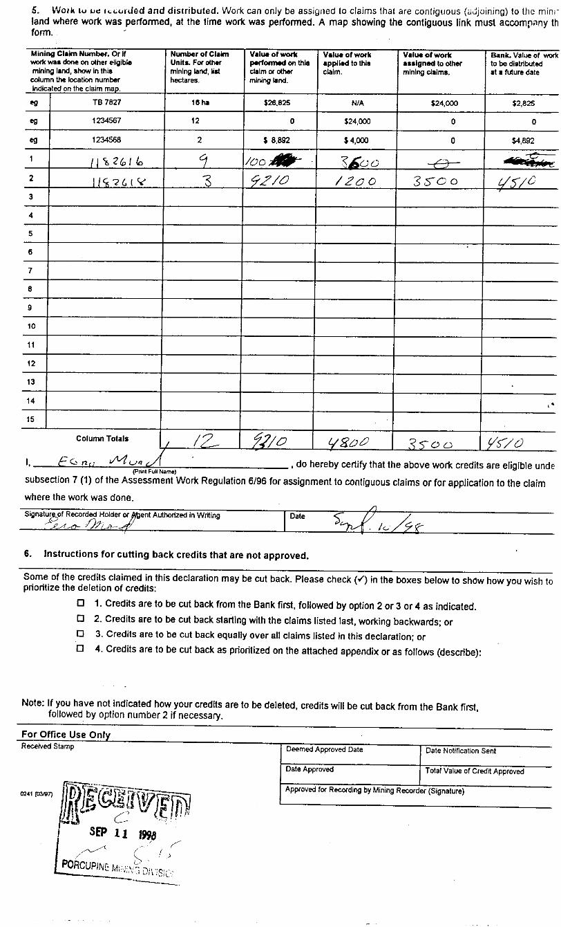
/OodttF- -
5^/3
ft/0
Value of work applied to this claim.
N/A
524,000
S 4,000
l&ioS 200
L/%02
Valueofwork ••signed to other mining claims.
524.000
0
0
-t^-
35~oo
3^00
Bank. Value of work to be distributed at a future date
S2,82S
0
KB92^.^ -^ ——
Yt/c
,*
y^/o, do hereby certify that the above work credits are eligible unde
(Print Full Nam*)subsection 7 (1) of the Assessment Work Regulation 6/96 for assignment to contiguous claims or for application to the claim where the work was done.Signature of Recorded Holder of Afcent Authorized in Writing Date
6. Instructions for cutting back credits that are not approved.
Some of the credits claimed in this declaration may be cut back. Please check (S} i n the boxes below to show how you wish to prioritize the deletion of credits:D 1. Credits are to be cut back from the Bank first, followed by option 2 or 3 or 4 as indicated.D 2. Credits are to be cut back starting with the claims listed last, working backwards; orD 3. Credits are to be cut back equally over all claims listed in this declaration; orD 4. Credits are to be cut back as prioritized on the attached appendix or as follows (describe):
Note: If you have not indicated how your credits are to be deleted, credits will be cut back from the Bank first, followed by option number 2 if necessary.
For Office Use Only—————^—^—-—^--—^-^—^Received Stamp
0241 (03/97)
PORCUPINE Ml
Deemed Approved Date
Date Approved
Date Notification Sent
Total Value of Credit Approved
Approved for Recording by Mining Recorder (Signature)

Ontario Ministry ofNorthern Developmentand Mines
Statement of Costs for Assessment Credit
Transaction Number (office UM)
Personal information collected on this form is obtained under the authority of subsection 6(1) of the Assessment Work Regulation 6/96, Under section 8 of the Mining Act, the information is a public record. This information will be used to review the assessment work and correspond with the mining land holder. Questions about this collection should be directed to the Chief Mining Recorder, Ministry of Northern Development and Mines, 6th Floor, 933 Ramsey Lake Road, Sudbury, Ontario, P3E 6B5.
Work Type
Pf?vS?*t-t^6
6t'-oPH U S i c i ( t '^
f* 6. ta P /M^f o f ^/4 6 fRofttes
Ui^^i w f) 'DfttCLi'svfa
^•o/u-sw * ?*i*Jx
'/Q*S*V*
{/*szc^T7;"6
Units of WorkDepending on the type of work, list the number of hours/days worked, metres of drilling, kilo metres of grid line, number of samples, etc.
2 d/q / S
f- f /C^7
, ^^
36*rr^- ^/V/
S", b" J6^
Associated Costs (e.g. supplies, mobilization and demobilization).
Transportation Costs
'7^^ /^ /^/^ " 4 6 -f
Food and Lodging Costs
Cost Per Unit of work
fi^ i 5 o / c/ *4 Y
1 1 o//^tfr x Xrf /SO /^/^}y
{of I *\ f "T f\ /* f rf 1 v f L/ *^ V^H*'
^^- /^\lttf/S Xy X ^ X 5'-f-^o/^
•^S-o//^
Total Cost
S o a - o c
Wd.tcS TO . c c
t-\ ^ S (3 . O cD
l COO-00
ft*'- vo
f i n^ac
tf&co.vo
•r—,
T^J-z^-
Total Value of Assessment Work
Calculations of Filing Discounts:
1. Work filed within two years of performance is claimed at 100*16 of the above Total Value of Assessment Work.2. if work is filed after two years and up to five years after performance, it can only be claimed at 500Xo of the Total Value of Assessment Work. If this situation applies to your claims, use the calculation below:TOTAL VALUE OF ASSESSMENT WORK x 0 .50 = Total S value of worked claimed.
Note:- Work older than 5 years is not eligible for credit.- A recorded holder may be required to verify expenditures claimed in this statement of costs within^&^YB-^f arequest for verification and/or correction/clarification. If verification and/or correction/ Minister may reject a!! or part of the assessment work submitted.
T^TSEP !Certification verifying costs: GEOSCIENCE ASSESSMENT
Of F ICE____,(please print full name)
, do hereby certify, that the amounts shown are as accurate as may
while conducting assessment work on the lands indicated on
//#t.jQ6rZ- _________ j am autnorj2etj(recorded holder, agent, or state company position with signing authority)
to make this certificatku^ V, ,
0212(02/96)
Signaturer~ Date
7?

Ministry of M inistere duNorthern Development Developpement du Nordand Mines et des M ines Ontario
Geoscience Assessment Office 933 Ramsey Lake Road
October 5, 1998 6th FloorSudbury, Ontario
EERO E. MORD P3E 6B5RR#1CONNAUGHT, Ontario Telephone: (888) 415-9846PON-1AO Fax: (877) 670-1555
Visit our website at: www.gov.on.ca/MNDM/MINES/LANDS/mlsmnpge.htm
Dear Sir or Madam: Submission Number: 2 .18793
Status Subject: Transaction Number(s): W9860.00763 Deemed Approval
We have reviewed your Assessment Work submission with the above noted Transaction Number(s). The attached summary page{s) indicate the results of the review. WE RECOMMEND YOU READ THIS SUMMARY FOR THE DETAILS PERTAINING TO YOUR ASSESSMENT WORK.
If the status for a transaction is a 45 Day Notice, the summary will outline the reasons for the notice, and any steps you can take to remedy deficiencies. The 90-day deemed approval provision, subsection 6(7) of the Assessment Work Regulation, will no longer be in effect for assessment work which has received a 45 Day Notice. Allowable changes to your credit distribution can be made by contacting the Geoscience Assessment Office within this 45 Day period, otherwise assessment credit will be cut back and distributed as outlined in Section #6 of the Declaration of Assessment work form.
Please note any revisions must be submitted in DUPLICATE to the Geoscience Assessment Office, by the response date on the summary.
If you have any questions regarding this correspondence, please contact Lucille Jerome by e-mail at [email protected] or by telephone at (705) 670-5858.
Yours sincerely,
ORIGINAL SIGNED BYBlair KiteSupervisor, Geoscience Assessment OfficeMining Lands Section
Correspondence ID: 12921
Copy for: Assessment Library

Work Report Assessment Results
Submission Number: 2.18793
Date Correspondence Sent: October 05, 1998 Assessor: Lucille Jerome
First Claim Number1182616
Township(s) l Area(s) PHARAND
StatusDeemed Approval
Approval Date
October 01, 1998
Transaction NumberW9860.00763
Section:9 Prospecting PROSP 14 Geophysical EM 16 Drilling PDRILL
Assessment work credit has been redistributed, as outlined on the attached Distribution of Assessment Work Credit sheet, to better reflect the location of the work.
Correspondence to:Resident Geologist South Porcupine, ON
Assessment Files Library Sudbury, ON
Recorded Holder(s) and/or Agent(s):EERO E. MORD CONNAUGHT, Ontario
Page: 1Correspondence ID: 12921
Distribution of Assessment Work Credit
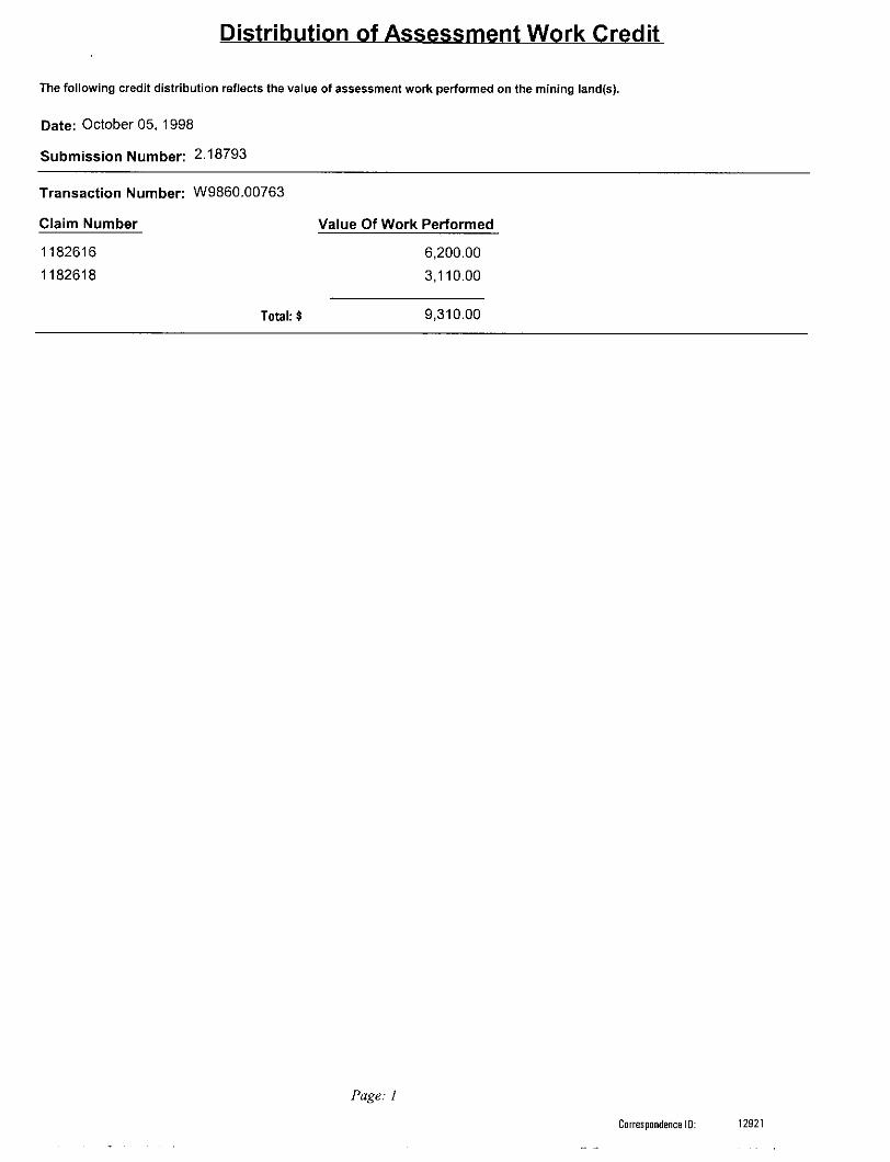
The following credit distribution reflects the value of assessment work performed on the mining land(s).
Date: October 05, 1998
Submission Number: 2 .18793
Transaction Number: W9860.00763
Claim Number Value Of Work Performed
1182616 6,200.001182618 3,110.00
Total:? 9 ,310.00
Page: l
Correspondence ID: 12921

pan
to O
O
G-2
362
Htfb
VH
D
1M
b'
G-2
862
555
IZ 3
DW
5 g
i O m
C 2
r —
i52
to o
cZ
CD
•B S
**
s *
f* P
b
X C
D 3 Z
cofT
^jj
og^oo'*
-0'-
1' oW
^0
3:S
5^H
Hc2
"i
O2 ^
z
5
H "
^ ^ 5
C
Z S
-rrn
OC
DO
zS
^ —
j- l*
O
. H
!D?m
'
C
. H 3
DZ
^O
J*
: o m
z- w
i
m
l \
f
S
f
- 2 i
Z
a
Z
S i
*^
f"
aO
-
C)M
O
X
Sil
> 9 ,
m
8 S o 39 > •n 39
l
id
m
r
aj
^
o
—,
s w
KE
NO
GA
MIN
G
TOW
NS
HIP
\ o
3s
o
r i
O) o O) x
L
O O)
C
dIH
SN
MO
i
f s J" B-
J*
C J) c M ID
OD at
H
(D O O* ro
V
! a.
CD l OJ
CD en OJ
H
Zs
H du
"Dn
s5
" ^
- w
i—
S m
o(A •H X
* H <
J O)
fi '
f o a
2.
S
•e CO o
T)
o go
Jg
Q
11 CO
V* c
m
L l
Z T
O
*
HO
Flo
o o c
im
gP
oo m
Vi o m o o o
g is s 8
o m
"CO
k
m ?
w *
o
3
>
mO 3
01 o | ITi
Z o m
m to m l/)
-
O
~
W l
. H
cm
o
O
O c z
s zCD
o
i 5
5 *
25
H
S
?
g
o
H
Z
H
0
O
w
5
w
O
S? S?
3
33
w
m
3
flo
Z
l—
-Cz
ci;
C z5 i z o
T) D
O
O C
3
m Z
oK
O
O a
'3 o
^ c
a i o
3
CO S S
o C/3
O 30 D
00
30
—-z s
m 3
V) m S
O z c z
* i w ^
O 3
O
33
^S
fH
z 3
> ^
C CD O
H ^
o tom m
P
O Z O
3 O o l VI H
m •o r- Z
O C o z o o c o z (D T
W
C
~
T
—
I"
O
C
C
3
5 r
S q r-
O
m^
o f
c lg m ^
<
m
O Z
m
in
lillr
3-2
865
6-3
30
2

k
^ 5
^J JS
t
t; ? S.S
* av
; *
hw
\!J
^
?^
^05
J
-- (i
TN
^L
J
\\\\
\
— ?6 7
: oM
•^
O
**^ **
~-
O
;llV
IO
O
V' LC
2/7
zd
j 0
7
oH
M
Ci
O
01c~COMOo(MO
4
[S

&J"*
/v
S/f St S? l. ^i j
^* J
42A04HH2002 2.18793 PHARAND 220
42A04NW2002
2.18793
PHARAND
.S?N
x^/4
It i
/**
ft*"
c} ///7/vtt f
1666**b
m - ^**/** /o^rr
42A04NW2002 2.18793 PHARAND 240

c*.OMc
l S
F-3
42A04NW2002 2.18793 PHARAND 250