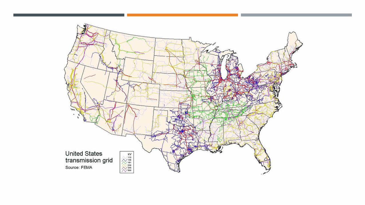
phasor measurement unit (pmu) - the best groupbest.eng.buffalo.edu/research/seminar slides...
TRANSCRIPT

PHASOR MEASUREMENT UNIT (PMU) AKANKSHA PACHPINDE

INTRODUCTION

OUTLINE
¡ Conventional control centers
¡ Introduction to Synchrophasors
¡ A generic PMU
¡ Applications of PMU
¡ Role of GPS
¡ Cost profile of PMU with GPS
¡ PMU with IEEE 1588

TASKS PERFORMED BY CONTROL CENTER

¡ Data is acquired from SCADA every 2s or so
¡ State estimation carried out to provide state of
system
¡ Load forecast carried out every 15mins
¡ AGC used balance power generation and load
demand
¡ Contingency analysis carried out
¡ OPF for transmission- constrained economic
dispatch
¡ Historical and forecasted data stored in storage
devices
¡ Various copies of data coordinated, synchronized
and merged in databases
¡ Control centers integrate horizontally & vertically

INTRODUCTION TO SYNCHROPHASORS
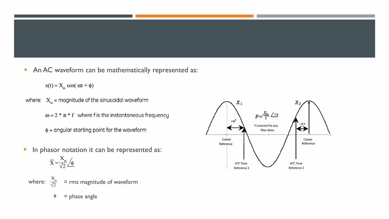
§ An AC waveform can be mathematically represented as:
§ In phasor notation it can be represented as:
where: = rms magnitude of waveform
= phase angle


A GENERIC PMU

Current/voltage signal from Instrument Transformer
Restricts bandwidth to satisfy Nyquist criterion
Analog-to-digital converter
Calculates positive-sequence estimates
Communication links to higher level
- Provides 1 PPS signal - Time- tagging

An architecture involving the following must exist in order to realize the full benefit of the technology
¡ PMUs
¡ Communication links
¡ Data concentrators

MEASUREMENT ACCURACY REQUIRED BY SYNCHROPHASOR STANDARD

¡ The value of Total Vector Error (TVE) < 1%
¡ Possible sources of error- magnitude, angle and timing
¡ Only magnitude error < 1%
¡ Only phase error < 0.573º
¡ Only time error < 31.8µs for 50 Hz system and 26.5µs
for 60Hz system

APPLICATIONS OF PMU
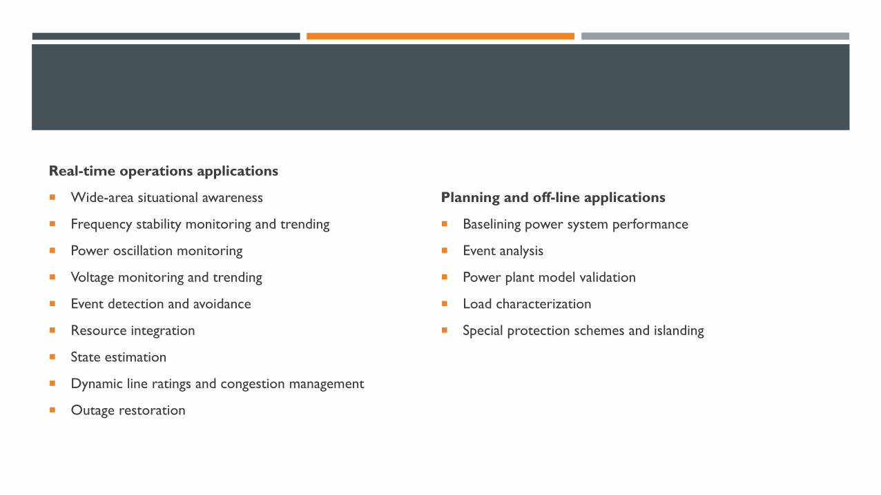
Real-time operations applications
¡ Wide-area situational awareness
¡ Frequency stability monitoring and trending
¡ Power oscillation monitoring
¡ Voltage monitoring and trending
¡ Event detection and avoidance
¡ Resource integration
¡ State estimation
¡ Dynamic line ratings and congestion management
¡ Outage restoration
Planning and off-line applications
¡ Baselining power system performance
¡ Event analysis
¡ Power plant model validation
¡ Load characterization
¡ Special protection schemes and islanding


ROLE OF GPS
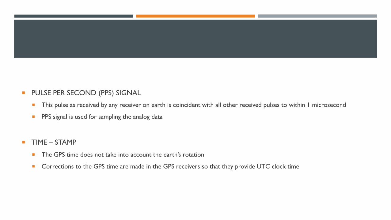
¡ PULSE PER SECOND (PPS) SIGNAL
¡ This pulse as received by any receiver on earth is coincident with all other received pulses to within 1 microsecond
¡ PPS signal is used for sampling the analog data
¡ TIME – STAMP
¡ The GPS time does not take into account the earth’s rotation
¡ Corrections to the GPS time are made in the GPS receivers so that they provide UTC clock time

COST PROFILE OF PMU WITH GPS

¡ Total installed cost of the technology includes cost of – device, design
and engineering, labor and material, any needed construction
¡ Cost of the device – one-quarter of the total cost
¡ Upgrades cost considerably less than installing new PMUs
¡ Projects installing a greater number of PMUs or PDCs did not have
lower average costs per device.

REASONS FOR HIGH COST
¡ GPS requirement
¡ Data storage needs
¡ Communication infrastructure requirement
¡ Changes required in substation like new busbars, additional CTs and PTs
¡ Downtime, labor cost, commissioning costs
¡ Limited experience
¡ Projects more about research, testing and demonstration

PMU WITH IEEE 1588
¡ Precision Time Protocol (PTP) was first defined in IEEE 1588- 2002 and upgraded in 2008
¡ It is designed for local systems requiring accuracies beyond those attainable using Network Time Protocol
¡ Designed for applications that
¡ Cannot bear the cost of a GPS receiver at each node OR
¡ For which GPS signals are inaccessible

IEEE 1588 has three types of clocks:
¡ Master clock- A clock which is controlled ideally by a radio clock or a GPS receiver
¡ Boundary/ Transparent clock- A clock in a transmission component like an Ethernet Switch
¡ Ordinary clock- A clock in an end device

¡ Assuming that the master-to-slave and slave-to-master propagation times are equal, the offset and propagation time can be computed as follows:
¡ Synchronization accuracies better than 1 sub-microsecond can be achieved
¡ PTP is supported by Ethernet and TCP/ IP

¡ Reallocation of time signals is done to bring the samples in their correct position
¡ The number of samples ‘N’ coming between two successive PPS edges is evaluated and the new sampling interval is calculated as inverse of ‘N’
¡ After reallocation, samples are passed to the DFT block
¡ Does not require GPS at every node
¡ Communication costs lowered as based on Ethernet
¡ Eliminates the extra cabling requirements of 1PPS to propagate highly accurate timing signals
¡ Non-recurring engineering costs – firmware development
¡ Cost of goods sold – negligible as only requires modification in Ethernet physical layer to support IEEE 1588
¡ High grade oscillators required which are expensive
¡ Lack of testing equipment supporting IEEE 1588 v2 protocol

QUESTIONS ?

THANK YOU