phev development platform - us department of energy · phev development platform doe merit review...
TRANSCRIPT

PHEV Development Platform
DOE Merit Review 28 February, 2008
Theodore Bohn Theodore Bohn Argonne National Laboratory Sponsored by Lee Slezak
*Dan Bocci- low level controls software development This presentation does not contain any Dominik Karbowski- PSAT/High level controls software proprietary or confidential material

tt
Objective: Create an all-electric mode capable PHEV vehicle development platform with open controller as research tool.
FY08 Budget: $700k Spent $120k to date FY08 Budget: $700k, Spent $120k to date • There currently exists no ‘available’ PHEV, conversion or other, that is able to complete a UDDS cycle without starting engine. (due to power-split limitations) By creating an in-house PHEV development platform with open control system a wide variety of high level vehicle control strategies, such as blended mode vs all electric mode, can be evaluated.
PHEV development platform: - Can be used for evaluation of battery sizing methods and battery technologies, along with PHEV test procedures.
- Through-the-road parallel hybrid electric vehicle, based on a stock Saturn Vue Greenline mild hybrid platform with 75kW rear drive system and 10kWhr lii bion battery.
• Rear electric drive system is modular such that other comparable drive motors can be evaluated in other comparable drive motors can be evaluated in an apples-apples comparison.

Description of Experiment:Through-the-Road parallel hybrid(TTR)
• Through-the-road parallel hybrid electric vehicle with axle torque sensors front and rear to measure power ‘through-the-road’.
• Additional electric drive powertrain in the rear of the vehicle; interchangeable 120kW air cooled AC induction machine or 75 kWinterchangeable 120kW air cooled AC induction machine, or 75 kWliquid cooled permanent magnet motor; ~8:1 fixed gear ratio.
55kW Prototype, OEM motors
75 kW li id75 kW liquid cooled PM motor
Axle Torque sensors on all 4 ½-shafts to measure “through the road” power
120kW air cooled120kW air cooled AC induction machine

Future Tool for Vehicle-to-Grid and Smart Charging Experiments
• TTR PHEV Platform uses CAN communication for all components, including stock Saturn Vuepowertrain
10kWhr JCS • CAN communication, along with intelligent Li-ion battery chargers allows for Vehicle to Grid bi directionalchargers allows for Vehicle-to-Grid bi-directionalcharging experiments, as well as uni-directional ‘Smart-grid’ charging, controlled by utilities.• Comparison of various chargers and batteries are planned experiments for this platform.
‘reductive’ Integrated
8kWhr A12320kW AC150 Li-ion battery
V2G charger
1.6kW Brusa 120/240VAC charger
1.2kW DeltaQ 5kWhr PEV 6kW DeltaQPrototype charger
120/240VAC charger NiMH batteryy120/240VAC charger (repackaged 3X Camry packs +BMS)
6kW DeltaQ

AER PHEV Platform: EV Capability and Range Estimatesand Range Estimates
Vue20 Vue40 Vue10
EV Capability
Vue20 Vue40Vue10
Stock Escape/Prius
mi
Hymotion/CS Escape/Prius
0 5 10 20 30 40
Batt Energy
PHEVequivalent
mi Vue0
Batt Energy
PHEVequivalent = 55/45 City/Hwy, Based upon “petroleum displacement factor’” method SOC: 90% down to 20% total capacity

Accomplishments to Date:• Project initiated July 2006- vehicle donation solicitation to GM (pre-production mule), delivered autumn 2006.
• 2006-2007 Components procured: multiple 2006 2007 Components procured: multiple electric drive systems, gear boxes, HV batteries, custom drive shafts with torque sensors, fuel flow measurement hardware, control system hardware
•2006-2007 Vehicle modification/construction including batteries and rear drive system by custom fabricator.
•Jan 2007- Low level control system code completed
•Vehicle on display at HybridFest, July 2007
6

•
FY08 Work Plan, Accomplishments to Date: FY08 WorkPlan: • Complete low voltage control system wiring • Commission low level control system • Debug/overcome incompatibility obstacles with Saturn Vue powertrain fault detection systemdetection system. • Develop high level control software based on PSAT models • Debug interface software between high level and low level controls • Test vehicle on 4WD Chassis dynamometer as well as on-road • Perform requested studies for J1711 procedures refinement • Implement ‘shift-by-wire’ actuator to overcome Vue powertrain drag in EV mode.
FY08 Accomplishments to Date:FY08 Accomplishments to Date: • Low voltage control wiring completed and commissioned low level control system • Major progress on debug of complications due to Saturn Vue powertrain fault detection system- implemented several work around solutions (i.e. spoofing the Vue vehicle controls into allowing engine shut down at highway speed, restart, etc) • High level control software based on PSAT models nearly complete, untested. • Debug interface software between high level and low level controls • Tested vehicle on 4WD Chassis dynamometer during controls debug Tested vehicle on 4WD Chassis dynamometer during controls debug. • Ran briefly in EV only mode; triggered fault in JCS battery protection system.
7

•
Lessons Learned/Obstacles: Accomplishments for Remainder of FY08:
• Discovered Unique Mobility no longer supports CAN software upgrades for their motors built in 2006; replaced with UQM drive, built in 2007 with current version of processor. •• During debug of control system found that Vue powertrain controller identifiedDuring debug of control system found that Vue powertrain controller identified external engine shut-down as a fault…..and restarted engine (not convenient during EV only mode). • Found sensitivity in JCS BMS control system. Learned that battery controller produced in 2006 is no longer supported. This Battery was not intended for vehicle.
Accomplishments/Plans for Remainder of FY08Accomplishments/Plans for Remainder of FY08 • Install ‘shift-by-wire’ actuator on Vue automatic transmission to reduce drag. • Complete high level control software based on PSAT models, debug in vehicle. • Debug interface software between high level and low level controls. • When vehicle fully commissioned, run planned experiments. (J1711 blended mode, AER validation; intelligent charging experiments, compare/contrast various battery size/chemistry, as well as compare performance of various drive systems.) • Prepare for publicity events involving DOE PHEV technology/research Prepare for publicity events involving DOE PHEV technology/research.
8

?OEM PHEVs
APRF testing
Support of Other DOE Programs
Energy Storage Tech Team
-Cold weather/battery limitations -Cost reduction challenges -Charge-efficiency assumptions/studies
Battery HIL + Ultracap Studies
-Validation of battery sizing -Vehicle to grid operation impact on batteries
EE Tech Team PHEV D l tPHEV Development
Platform
-In-vehicle validation of electric motor performance -Vehicle to grid benchmark/embedded controls
MATT in APRF
J1711 J1711
- various control strategies- different chemistries
- EV operation issues
PSAT at ANL PSAT at ANL - Control system development andvalidation
9

-
Future Plans:
The TTR PHEV Development Platform project is a multi-year program with new The TTR PHEV Development Platform project is a multi year program with new initiatives related to incorporating new component technologies.
-Battery technologies; Larger format A123 li-ion batteries, Enerdel lithium titanate cells, Altain Nanotechnologies Lithium-titanate batteries; ultracapacitor-battery combinations
- Control algorithms including in-depth investigations on optimizing petroleum Control algorithms including in depth investigations on optimizing petroleum displacement via blended mode vs adaptively dispatched electric only operation.
- Exploration of small engine technology deployment in series PHEVs.
- This research builds upon previous modeling studies on ESS sizing, peak power/energy requirements of PHEVs. Some studies will be revisited with new insigghts from this PHEV Developpment Platform.
- Explore new ways to blend electrical energy with petroleum energy as a tool for SAE J1711 validation methods.
10

Active Combination of Ultracapacitors and BatteriesUltracapacitors and Batteries
for PHEV ESS
DOE Merit Review 28 February, 2008
Theodore Bohn Theodore Bohn Argonne National Laboratory
John MillerSponsored by Lee Slezak (Hardware Collaborator)
*Dan Bocci- Ultracap simulations/controls software This presentation does not contain any Neeraj Shidore- Battery HIL collaboration proprietary or confidential material

Objective: Investigate Benefits of Active Combination of Ultracapacitors and Advanced Chemistry Batteries
• Battery manufacturers generally agree that warranty claims on a PHEV sized battery pack is a major concern. Any technology that can prolong/ensure longer battery life may have more value in that capacity than the cost of that hardware/technology.
• Component cost and reliability are major concerns of most HEV/PHEV designers. This experiment will investigate the required additional costs of ultracapacitors andThis experiment will investigate the required additional costs of ultracapacitors and electronics as well as the differential benefits of this approach (i.e. apples-to-apples comparison of EES with/without ultracapacitors).
• New SOC control strategies for the ultracapacitor bank need to be developed.
• By limiting peak power delivered by the li-ion battery, especially in cold weather operation where the li-ion battery may be damaged at high loads the ESS operation where the li ion battery may be damaged at high loads, the ESS requires less over-sizing, thus saving battery costs.
• The ultracapacitor bank will be sized to absorb/source one regen braking/accel eventt.
12

-
Active Combination of Ultracapacitors With Li-ion Batteries (Phase I Experiment Hardware)
ABC-170 (170kW CAN ABC 170 (170kW CAN SOCb = controlled power supply f(Vb,Ib) Thermal ChamberSOCb {power electronics})
Ultracapacitor/Battery Experiment Hardware
dSpace Autobox Virtual Vehicle
Central control SOC control unit
Load
cur
rent
Con
trol
sig
nals
SOCu
Power electronics
To electric loads
Vol
taage
Cur
r eent
V
olta
ge
Cur
rent
SOC =SOCu
f(Vu)
B tt iBatteries
Ultracapacitors
Virtual Vehicle dSpace AutoboxCentral Control Unit
Maxwell 650F ((8 x 2.7v ea.))Dewalt/A123 Li-ion Battery Pack, 36v, 2.6ahr

$ $
Accomplishments to Date FY08 Budgget: $200k Sppend $20k to date
• Discussions with Maxwell Technologies about collaboration started in Spring 2007. • Feasibility studies and preliminary component/circuit level simulation performed in June 2007. • Capacitor hardware donated to ANL July 2007. Small capacitor bank assembled. • Dewalt 36v cordless tool pack purchased. Battery and charger/BMS characterized. Key Technology Improvement: Current Regulator Virtual Electrical Model TopologyCurrent Regulator Virtual Electrical Model Topology
Ra (active impedance, reflected by DC/DC converter) is very small; by dynamically adjusting this active impedance via power electronics current sharing is
14
impedance via power electronics current sharing is adjusted between the ultracapacitor and Li-ion battery
• -
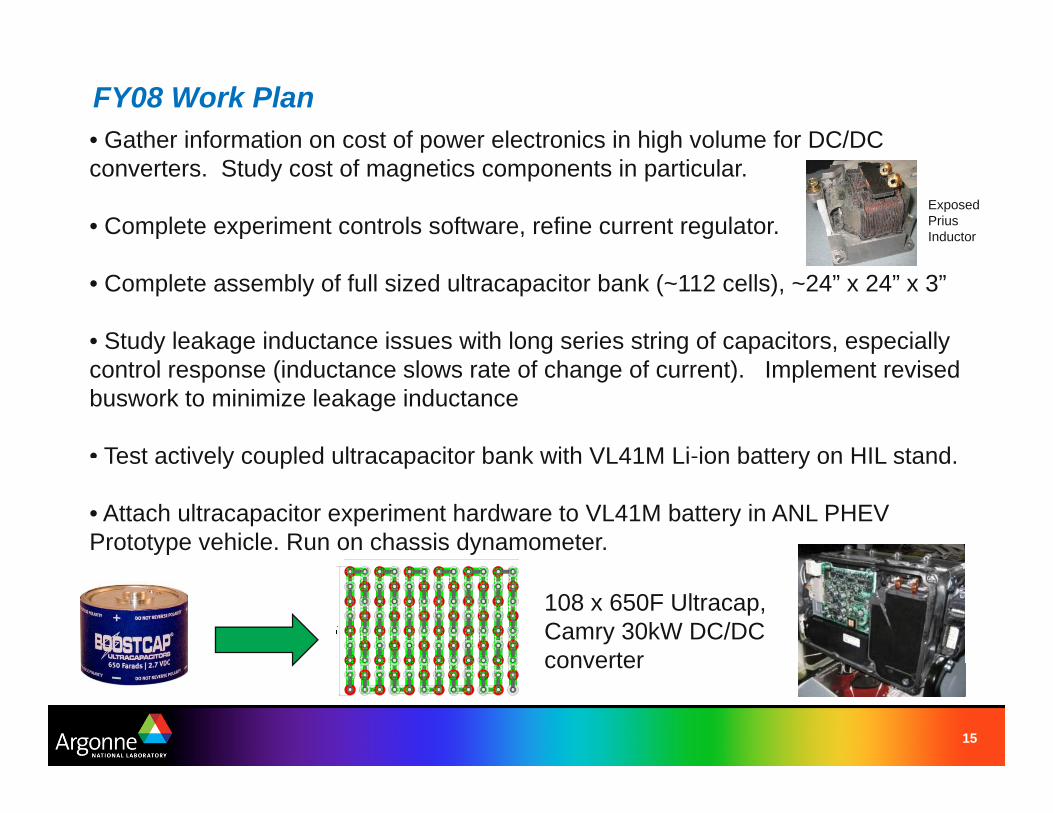
FY08 Work Plan • Gather information on cost of pp gower electronics in high volume for DC/DC converters. Study cost of magnetics components in particular.
Exposed Prius • Complete experiment controls software, refine current regulator. Inductor
• Complete assembly of full sized ultracapacitor bank (~112 cells), ~24” x 24” x 3”
• Study leakage inductance issues with long series string of capacitors, especially control response (inductance slows rate of change of current). Implement revised buswork to minimize leakage inductance
• Test actively coupled ultracapacitor bank with VL41M Li-ion battery on HIL stand Test actively coupled ultracapacitor bank with VL41M Li ion battery on HIL stand.
• Attach ultracapacitor experiment hardware to VL41M battery in ANL PHEV Prototype vehicle. Run on chassis dynamometer.
108 x 650F Ultracap, Camry 30kW DC/DC converterconverter
15

FY08 Work Plan- Progressively Higher Power Experiments 1 1kW power level emulated load/power 1. 1kW power level, emulated load/power
electronics, using Prius current profile UDDS{<100A}, voltage scaled; 1/6th
2. 1kW power level, physical motor loads1kW Dewalt motor, battery, torque sensor, servo load motor
3. 36v boost converter, based on Prius electronics (21kW max)electronics (21kW max)
4. Camry boost converter based (30kW) 5. Fully capable, commercially available,
CAN based 60kW DC/DC converter
16

t
FY08 Accomplishments to Date:ESS Model Assumptions, Results
Results: � Ultracap Model: Maxwell equivalent circuit model, 100 series Ultracap SOCAhrs Min = 26.1 % 650F modules – Batt = -0.6732 Max = 74.4 % � Battery Model: Johnson Controls-SAFT VL41M li-ion model – Cap = 0.5741 Ultracap Current� Power Converter: ((ideal)) Power in = Power out
– Cycle = -0.0991 Min = -104 A ((into capps))W t HWatt Hours Max = 97.4 A (out of caps) � Battery Current Profile : ANL Prius data,US06 drive cycle, stock – Batt = -194.368 Ultracap PowerNiMH battery, 20C – Cap = 161.677 Min = -22.2 kW (into caps)
– Cycle = 32.69 Max = 19.5 kW (out of caps) Battery Current Magnitude Histogram Battery Current Slew Rate Magnitude Histogram
50 7070
1515
With UltraCap System Without UltraCap System
Max w/ UC = 54.25 A Max w/o UC = 82.43 A
2020
10 10
0
With UltraCap System Without UltraCap System
Max w/ UC = 57 A/s Max w/o UC = 478 A/s Max w/o UC = 478 A/s
00 10 20 30 40 50 60 0 20 40 60 80 100
Current [A] SlSlew RRatte [A/ [A/s]]
45 60
40
5035
30
Per
cent
of t
ime
[%]
Per
cent
of t
ime
[%%]
40
25 30
20
5

Currents vs Time, Net Change in Battery Current
100 Component Currents during US06
50
100
ent [
A]
Total UC Power Converter Battery
Blue line is road load (battery current w/o ultracaps)
-50
0Cur
re
Green line is U-cap
50 60 70 80 90 100 -50
Time [s]
70 Ultracap SOC
60
OC
[%]
SO
current (dynamic)
Red line is new battery current- more averaged.
SOC is maintained 50
over this ‘real world’ 4040over this real world Prius current trace, on 30US06 segment
2050 60 70 80 90 100
Time [s]

?OEM PHEVs
APRF testing
Support of Other DOE Programs
Battery HILEnergy Storage Tech Team
PHEV Development Platform
Ultracap Studies Battery performance/reliability improvement study-Battery performance/reliability improvement study
-Explore other batteries best matched with U-Caps
PSAT at ANL EE Tech Team
-Power electronics component costs -Control bandwidth algorithms for SOC/tracking -Cost of embedded controls/processors
-Cold weather/battery limitations - Vehicle level simulations and -Cost reduction challenges component validation/sizing -Charge-efficiency assumptions/studies
19

Future Work:A ti bi ti f lt it ith b tt i f PHEV li ti i lti - Active combination of ultracapacitors with batteries for PHEV applications is a multi
year program.
- Studies and expperiments for ppower electronics compponents size and cost reduction as well as lower-cost controller hardware are planned for the future.
- This work will leverage interest from OEM’s, DOE EE-Tech Team & ES-Tech Team.
Papers / Presentations: – Advanced Capacitor World Summit; July 2007 “Battery HIL and
Decoupling Battery Load Transients With Ultracapacitor Storage” – SAE Hybrid Symposium, San Diego, CA Feb 14, 2008;
“Ultracapacitor Energy Storage Methods for PHEVs”– SAE Paper 2008-01-1003, “Dc-dc Converter Buffered Ultracapacitor
in Active Parallel Combination with Lithium Battery for Plug in Hybrid in Active Parallel Combination with Lithium Battery for Plug-in Hybrid Electric Vehicle Energy Storage”
– IEEE Vehicle Propulsion and Powertrain Conference, Harbin China, Seppt 2008,, “Dc-dc Converter Activelyy Cou ppled Ultracappacitor-Lithium Battery for Plug-in Hybrid Electric Vehicle Energy Storage”
20