photographic lens manufacturing and production technologies
TRANSCRIPT

Photographic Lens Manufacturing andProduction Technologies
by
Daniel Mark Kubaczyk
Submitted to theDepartment of Mechanical Engineering
in Partial Fulfillment of the Requirements for the Degree of
Bachelor of Science BMA SSACHUSETTS INSTITUTEOF TECIOLOGY
at theOCT 2 0 2011
Massachusetts Institute of TechnologyL LIBRARIES
June 2011 ARCHIVES
© 2011 Daniel M. KubaczykAll rights reserved
The author hereby grants to MIT permission to reproduce and todistribute publicly paper and electronic copies of this thesis document in whole or in
part in any medium now known or hereafter created.
Signature of Author ........................... . ................. .... .............
Depa ment of Mechanical EngineeringMav 6. 2011
C ertified by .................................................................... ..... ... ...................................................Douglas P. Hart
Profes "hncal EngineeringThes -is i p v -Sunn
A ccep ted b y ....................................................................... ....................... .........John H. Lienhard V
Collins Profe echanical EngineeringUndergraduate Officer

[This page left intentionally blank]

Photographic Lens Manufacturing andProduction Technologies
by
Daniel Mark Kubaczyk
Submitted to the Department of Mechanical Engineeringon May 6, 2011 in Partial Fulfillment of the Requirements
for the Degree of Bachelor of Science in Mechanical Engineering
Abstract
An investigation was conducted to determine the methods and processes required for themanufacture of photographic objective lenses. Production of photographic lenses requiresincredible precision in the melting, mixing, molding and machining of optical glass. Manualinspection methods are required to ensure optimum quality and to avoid inclusion of defects inglass. Manual assembly procedures are required to ensure delicate operation of glass elementsbut contribute significantly to the consumer expense of these lenses.
Newly developed technologies in the field of lens machining are discussed in terms ofcommercial advances and scientific advances. Companies like Canon have sought greaterautomation in pre-assembly procedures as well as a reduction in the number of machining steps.New advances including precision machining of aspherical lenses, fluid-jet polishing andmagnetorheological finishing are pushing the boundaries of lens machining and its characteristicsurface roughnesses to depths not seen before.
Thesis Supervisor: Douglas P. HartTitle: Professor of Mechanical Engineering

[This page left intentionally blank]

Acknowledgements
I would like to thank Professor Douglas Hart for granting me the freedom to explore this
topic on my own terms. I would also like to extend thanks to Professor Timothy Gutowski who
struggled with me in finding a suitable thesis topic.
I want to extend infinite gratitude to Canon whose virtual photographic lens plant helped
me to visualize just how photographic lenses are made and supplied a large portion of the images
seen in this thesis.
Many thanks to Peter Lu, whose dogged search for an enticing thesis topic helped me to
find something which sparked my passion.
Finally, I want to thank my parents and family - most of whom would understand almost
none of what is written in this document. I owe my diligence to them.

Table of Contents
Abstract........................................................................................................................................... 3
Acknowledgem ents......................................................................................................................... 5
Table of Contents............................................................................................................................ 6
List of Figures................................................................................................................................. 7
List of Tables ................................................................................................................................ 10
1 - Introduction............................................................................................................................. 11
1.1 - Technical Foundations of Photography ....................................................................... 11
1.2 - Cam era and Lens............................................................................................................. 13
2 - Photographic Lens M anufacturing....................................................................................... 19
2.1 -M aterial Selection and Processing ................................................................................ 19
2.2 - Lens M achining Processes........................................................................................... 24
2.3 - Finishing Processes and A ssem bly .............................................................................. 32
3 - Technological A dvances in Grinding .................................................................................. 40
3.1 - Physics of Grinding..................................................................................................... 40
3.2 - Com m ercial Advances in Grinding Technology ........................................................ 42
3.3 - Scientific Advances in Grinding Technology.............................................................. 48
4 - Conclusion .............................................................................................................................. 54
Bibliography ................................................................................................................................. 55
6

List of Figures
Figure 1-1: A digital photograph .............................................................................................. 11
Figure 1-2: Cutaway view of a DSLR camera showing critical components .......................... 14
Figure 1-3: Nikon's Vibration Reduction system for preventing image blur ............................ 15
Figure 1-4: 35 mm focal length lens with a narrowed aperture ................................................... 16
Figure 1-5: (a) Photograph taken with a narrow aperture showing sharpness over a great distance(b) Photograph taken with a wide aperture showing limited sharpness ................................... 16
Figure 1-6: CCD sensor from a Nikon D40 DSLR camera ..................................................... 17
Figure 2-1: Optical glass types representing a wide range of refractive indices and Abbe'snumber (B indicates boron, K indicates crown-type glasses, F indicates flint-type glasses, Sindicates heavy glasses [high refractive index], L indicates light glasses [low refractive index]and La indicates lanthanum ) ................................................................................................... 20
Figure 2-2: Pouring of blended glass melt into steel mold for cooling ................................... 21
Figure 2-3: Homogenized glass being cooled on a continuous temperature-gradient coolingfurnace .......................................................................................................................................... 22
Figure 2-4: Vertical milling of glass plates. a - Glass plate, b - diamond milling disc, c - vacuumch u ck ............................................................................................................................................ 22
Figure 2-5: Automated pressing of lens blanks into a general lens shape .............................. 23
Figure 2-6: Lenses fixed to blocking with pitch ..................................................................... 25
Figure 2-7: Rough grinding of convex lenses, a - machine arm, b - grinding shell, c - blockholder, d - abrasive grains ........................................................................................................ 25
Figure 2-8: Rough grinding of large aperture lenses (the white film is lubricant) .................. 26
Figure 2-9: Grinding increments for a lens with a finished radius of 100.00 mm, a - Mold radius= 100.6 mm, b - milled and roughed radius = 100.15 mm, c - medium ground radius = 100.1 mm,d - fine ground radius = 100.05 mm, e - finest ground radius - 100.02 mm, f - finished radius =100 .00 m m ................................................................................................................................... 27
Figure 2-10: Fine grinding of lenses (gray disks) with precision diamond grinding tools (white)....................................................................................................................................................... 2 8
7

Figure 2-11: Lens decentration, a - axial displacement centring error, b - optical axis,........... 30
Figure 2-12: Centring accuracy that can be achieved by optical methods depending on the sum oflens surface curvatures (1/r1 + 1/r2) with concave radii having a negative sign ....................... 31
Figure 2-13: Centring of an optical lens in between brass chucks shortly before edge grinding.The operator centers the lens using a microscope (not seen).................................................... 31
Figure 2-14: Vacuum evaporator with optical lenses awaiting cleaning and coating ............. 32
Figure 2-15: Anti-reflection coating inducing destructive interference in reflected light rays ... 33
Figure 2-16: Canon EF 500mm f4L IS II USM Telephoto Lens. Telephoto lenses such as this areoften made of many lenses, 10 or more, and thus require meticulous assembly. (Cost = $7,000)....................................................................................................................................................... 3 4
Figure 2-17: Cross-sectional view of the lens seen in Figure 2-16. The inclusion of more lenselements increases assembly costs significantly....................................................................... 35
Figure 2-18: Glass lenses are assembled into a lens barrel with protective gloves to minimizetransfer of skin oils and other debris......................................................................................... 35
Figure 2-19: Final assembly of the two sub-barrel assemblies of the Canon EF 500 mm lens seenin F igure 2-16................................................................................................................................ 36
Figure 2-20: Potential centering error within a optical system as a result of unequal lensdiameters, a - Centring error within the system, b - optical axis of the convex lens, c - opticalaxis of the flint lens, d - diameter difference between the lenses............................................. 37
Figure 2-21: Addition of exterior components to the lens barrel assembly............................... 37
Figure 2-22: Testing a completed optical system for axial imagery, a - Centering collet formounting the lens to be tested, b - collimator objective, c - illumination for the collimatorgraticule, d - collimator graticule or pin hole, e - rotating ground glass disc, f - observationmicroscope, g - lens under test (complete photographic objective)........................................ 39
Figure 3-1: Schematic of chip formatio by an abrasive grain with a wear flat. The rake angle(angle between grain and chip) is highly negative and the shear angle is very shallow. Theseparameters would make cutting difficult if the material removal rate weren't so low. ........... 41
Figure 3-2: Canon's grinding and polishing apparatus used to convey and grind spherical lensesthrough autom ation ....................................................................................................................... 43
Figure 3-3: (left) Brittle cutting with abrasive grains cutting beyond the critical depth (right)ductile cutting with abrasive grains cutting short of the critical depth ..................................... 44

Figure 3-4: Comparison of brittle cutting and ductile cutting ................................................. 45
Figure 3-5: Canon's polishing apparatus with active control systems to monitor and directm achining param eters ................................................................................................................... 46
Figure 3-6: Machining cost increases significantly as smoothness reaches the nano-scale ........ 47
Figure 3-7: Semi-rigid tooling applied to grinding ................................................................... 49
Figure 3-8: Schematic of predictive model used to estimate lens surface characteristics ........ 50
Figure 3-9: Predicted and measured values for final surface roughness as a function of spindlesp eed ............................................................................................................................................. 5 0
Figure 3-10: MRF with process parameters............................................................................. 53

List of Tables
Table 2-1: Radii of grinding shells for various grinding stages, relative to finished radius ..... 2
Table 3-1: Tolerances in optical production, circa 1988 ......................................................... 42
Table 3-2: Peak/valley errors induced as a result of thermally-significant parameters ........ 51

Chapter 1
Introduction
1.1 - Technical Foundations of Photography
While a well-trained photographer can often "make do" with inferior equipment if theoccasion demands, equipment of optimum quality is a very great advantage.
-Ansel Adams
Figure 1-1: A digital photograph (Credit: Author)

Photography is a method for capturing an energy record through means of a permanent
chemical reaction in the case of film or through the excitation and storage of charged elements in
capacitive elements in the case of digital imaging sensors. Regardless of its purpose, whether it
be informative, scientific, artistic or some combination thereof, photography is technically
intensive in each and every process that transforms a real and physical scene or object into a
processed image.
Modem digital cameras incorporate many engineering implements in order the facilitate
image capture. First and foremost, high-precision optics are essential to visual reproduction of a
subject along with the electro-mechanical apparatuses that provide the flexibility for such optical
instruments to work in varied settings. Electrical components and sensors have enabled instant
image review as well as live view (previewing and image before it is taken) along with
automation of tedious tasks such as sensor cleaning, light sensing, focusing and bracketing.
Storage and editing images have become drastically more time and space-efficient as a result of
digital technology; thousands of images can be stored in thin memory cards and edited within
minutes after capture.
Such technical intensiveness requires a minimum level of technical aptitude for basic
proficiency and even greater stores of knowledge for more advanced photographers. A critical
aspect of this technical awareness, especially from an engineering standpoint, is an
understanding of how these products are manufactured and how they achieve such advanced
levels of performance. While expert photographers can easily get by without such knowledge
those who comprehend and appreciate the complexity and craftsmanship of their optical and
photographic instruments will stand at a technical advantage.

1.2 - Camera and Lens
The engineering and optical science behind photographic cameras and lenses are in
immense topic deserving many volumes of elucidation; the following is nothing more than a
cursory summary. The information provided will focus on modem digital cameras due to their
prevalence in consumer and professional spheres as well as their use of state-of-the-art
technology.
The modem digital camera offers the user a multitude of options which allow for almost
limitless sets of customizable settings. Even consumer-friendly "point-and-shoot" cameras
include many settings for flash, color temperature, time delay, shake reduction and more while
high-end professional digital single-lens reflex cameras (DSLR) contain many more adjustable
features. Yet almost all cameras contain a core set of optical, mechanical and electrical
components which enable image capture.
A digital DSLR camera can be broken into two subsections: body and lens. The body
houses all of the camera's components outside of the lens including the shutter, mirror, image
sensor, viewfinder, pentaprism, display screen, battery, image processor, flash bulb and an array
of switches, dials and buttons used to alter exposure settings. The lens houses the optical glass
lenses used to focus incoming light into an image on the sensor. The lens is also responsible for
housing the aperture ring, focusing controls, focal length control and can also include
mechanisms for vibration reduction (VR). Figure 1-2 shows some of these features as well as the
path of light rays through the camera/lens apparatus.

Folding flash bulb
perture
Pentaprism
Figure 1-2: Cutaway view of a DSLR camera showing critical components (1)
Light enters the camera/lens apparatus through the glass of the lens. Based on a variety of
optical properties and settings, light may contact that glass at many different angles and travel
varying paths in order to bring an image onto the sensor. Light is refracted through the glass
elements at certain angles based on the glass lens' structure and optical properties. Most lenses
allow for relative motion between the various glass elements in the lens allowing for changes in
focal length and focus distance. Focal length corresponds to the distance between where light
rays intersect the lens plane and where they converge. Larger focal lengths correspond to
shallower angles of refraction and allow for magnification of distance objects. (2) Lenses with
larger focal lengths (typically from 100 - 500 mm in photographic cameras) are known as
"telephoto" lenses and are often seen on the sidelines of sporting events. Lenses with smaller
focal lengths correspond to sharper angles of refraction and wider angles of view. Such lenses
are known as landscape lenses (typically with focal lengths from 12 - 55 mm). (2)
Viewfinder
LCD screen
Mirror
Sensor

Focusing distance is the distance from the lens to an external object that gives perfectly
focused lights at the focal point of the lens. Objects nearer the focusing distance tend to appear
sharper and clearer than objects a great distance away from the focusing distance. Control of
focal length and focusing distance allows for versatile operation of a camera lens. Most modem
camera/body systems are capable of autofocusing images through electronic distance
measurement, also known as triangulation. Such a process is similar to how humans perceive
depth through the angular convergence of the eyes. (3)
Some lenses contain vibration-reducing elements which help to keep the lens stable at
longer exposure times where undesired or unavoidable movement of the camera/lens is sufficient
to blur or distort the image. This motion is counteracted by sensing and compensating for the
unwanted movement. Nikon's Vibration Reduction (VR) mechanism utilizes piezoelectric
sensors that analyze any lens displacement at a rate of 1000 Hz and instruct the voice-coil motors
(VCM) how to correct for such movements, as seen in Figure 1-3. (4)
Anglar velocity sensor 1 Y Yawifng(detects pitching) (horizontal movement)
VCM(shifts the VRlenrs INb
vertically)
VR Lens
Pitching(verticalmovement)
ZOirection of Anguilar velocty sensor 2optical axis VCM (detects yawing)
(shifts the VR lens horizontally)
Figure 1-3: Nikon's Vibration Reduction system for preventing image blur (4)

At some juncture in the lens, light rays pass through (or are impeded by) the aperture, as
seen in Figure 1-4. The aperture controls the amount and angle of light that passes through the
lens.
Figure 1-4: 35 mm focal length lens with a narrowed aperture (3)
As the aperture narrows, less light is admitted into the camera but the admitted rays
become more collimated (more parallel), allowing for a sharper image with relatively more
objects in-focus. As the aperture widens, more light is admitted, allowing for faster shutter
speeds but also leading to a blurrier image around the focusing distance. In this case, the distance
over which the image will retain sharpness decreases, as seen in Figure 1-5.
Figure 1-5: (a) Photograph taken with a narrow aperture showing sharpness over a great distance (b)Photograph taken with a wide aperture showing limited sharpness (5)

Most digital cameras use charge coupled devices (CCD) as sensors which capture
incident radiation and convert it into an analog signal comprised of electrons in an array of
pixels. Complementary metal oxide semiconductor sensors (CMOS) are also used and use
transistors at each pixel location. (2) Each pixel on a sensor represents one data point that makes
up an image; thus raw, unprocessed images have the capability of storing the number of bytes
that is essentially equivalent to the number of pixels on a camera's sensor. Larger stores of pixels
give higher resolution and higher image quality (especially for enlargements). Many modem
digital cameras house sensors with more than 10 megapixels with high-end professional DLSRs
topping out at 25 megapixels. As a reference, typical 35mm film has a resolution of about 20
megapixels. (2) Figure 1-6 shows a typical CCD sensor. After images are converted to digital
signals they are then processed by the camera's internal hardware and stored in memory.
Figure 1-6: CCD sensor from a Nikon D40 DSLR camera (3)
Single-lens reflex cameras have the enormous advantage over double-lens reflex cameras
(now mostly obsolete) by having the photographer see through the very lens through which the
photograph will be taken. This is accomplished by an angled mirror and a piece of optical glass
known as a pentaprism. The pentaprism, seen in Figure 1-2, rectifies the image and allows the
user to see through the viewfinder almost exactly the image that will be projected onto the

sensor. Many cameras also feature "live view" which shows the user a digital display of the
photograph on an LCD screen, thus avoiding having to peer through the viewfinder to preview
the image.
Modem cameras contain a plethora of technological upgrades that enhance and better
integrate all of these features. For our purposes, full exposition of these is unnecessary for the
following discussion regarding manufacturing processes. A basic understanding of a modem
camera's optical and electromechanical complexity has been provided and will suffice for
proceeding discussion.
Chapter 2
Photographic Lens Manufacturing
2.1 -Material Selection and Processing
Prior to the 20t century, most optical glasses were made up of materials similar to those
found in modem non-optical glasses (windows, food containers, etc.) These glasses belong
mainly to two groups: simple crown glasses that are formed from SiO2(fused quartz, about 70%
by weight), Na2 CO3 (soda, 15%) and CaO (lime, 12%) and flint glasses made from lead oxide
(PbO, 14%) and potash (K20, 14%) along with SiO2 (55%) and other oxides. (9)
A much wider range of optical glasses soon emerged in the 20"' century, first with the
incorporation of barium oxides and boron oxides. These compounds yielded very low dispersion
(leads to chromatic aberration which induces fringes of color where sharp edges should be seen)
at high refractive indices (barium oxides) and at low refractive indices (boron oxides). (9) The
index of refraction of a given material determines the angle at which incident light will travel
through the medium. Incorporation of novel materials greatly expanded the optical range of

glasses used for photographic instruments and allowed for more freedom in optical design and
engineering.
Optical glasses used today contain a myriad of materials and most photographic lens
manufacturers keep the chemical content of their glass lenses as proprietary as possible. Figure
2-1 shows the range of optical glasses available to modem manufacturers. Many of these glasses
contain rare earth materials, especially lanthanum (indicated by "L" in Figure 2-1. (9) Abbe's
number is a dimensionless parameter that quantifies dispersion (high Abbe = low dispersion).
Fluoro-_b
B F90 8 7I- 60
Abbe's numnber,50 40 30 20
Figure 2-1: Optical glass types representing a wide range of refractive indices and Abbe's number (Bindicates boron, K indicates crown-type glasses, F indicates flint-type glasses, S indicates heavy glasses [high
refractive index], L indicates light glasses [low refractive index] and La indicates lanthanum) (9)

Once material selection is made and optical properties for the soon-to-be-made lenses are
determined, the raw materials (in the form of a grainy powder) are mixed together in a mixer to
filter out impurities such as iron (to the order of parts per million) that reduce light transmittance.
(10) After mixing the raw ingredients, the mixture is heated in a crucible and blended together
above the melting temperature of the included materials (around 1500 "C) with special stirring
equipment. (11) The contents are then poured into a large, flat rectangular steel mold to cool and
solidify before further processing, as seen in Figure 2-2. (9)
Figure 2-2: Pouring of blended glass melt into steel mold for cooling (10)
The cooled glass is then crushed into smaller pieces before undergoing further melting
processes. The glass is then cast into a continuous fusion machine (at 1300*C) where it
undergoes fusion, mixing/churning, clarification and homogenization. The liquid glass is shaped
into a long sheet that cools very gradually along a temperature-gradient, slow cooling furnace
seen in Figure 2-3. The resulting output is a homogenous glass mixture that is devoid of air
bubbles. The control of temperature and the fusing/cooling processes are critical for the
production of high-quality optical glass.

Figure 2-3: Homogenized glass being cooled on a continuous temperature-gradient cooling furnace (10)
Prior to cutting, glass sheets can be ground close to their specified thickness (usually
leaving an excess of 0.3 mm for future finishing). (12) The glass plates are secured lightly to a
fixture with wax and ground using rough iron abrasives or diamond milling tools, as seen in
Figure 2-4.
Figure 2-4: Vertical milling of glass plates. a - Glass plate, b - diamond milling disc, c -vacuum chuck (12)
Test pieces from each piece of glass are cut out and run through a quality inspection to
test for defect before further manufacturing processes are carried out. After passing the
22

inspection is passed, the lenses are repeatedly ground and heat-pressed (seen in Figure 2-5) into
lens blanks that take on a general lens shape that will be finely tuned in future grinding and
polishing operations. (10) The glass lenses are formed such that they are approximately 10%
oversized from their final dimension. (12)
Figure 2-5: Automated pressing of lens blanks into a general lens shape (10)
The lens blanks, now having a shape very similar to that of a finished lens, are heated to
500 0C in an electric furnace and are annealed to remove internal stresses developing from
pressing and shaping operations. The lens blanks are allowed to cool at a very slow rate to
prevent the reformation of thermal gradients and thermal stresses. Residual press marks and
other surface deformities still reside on the lens blanks and are to be removed to achieve an
optimal surface finish through machining processes. (10)

2.2 - Lens Machining Processes
After general shaping processes, photographic lenses are precisely machined through a
series of steps that begin with rough cuts used to remove bulk material and end with polishing
operations that leave the surface of the finished lens sufficiently smooth.
Rough grinding is carried out first. This type of machining gives the lens the desired
curvature using ultra-hard diamond grindstones. Lenses are fixed on the outside of a fixture
block using either the pellet-sticking method or the hard-block holding tool method. Many lenses
are fixed on a block to facilitate economical production of lenses. (10) The fixturing process
proceeds as follows: the radii of the block holder and the laying-in shell are calculated in order to
set the lenses such that they are ground at the correct spherical radius. The lenses are then fixed
to the block holder with pitch pellets (a sticky adhesive that melts around 70 0C) around the
melting point and is then cooled with water so the lenses stick to the block holder. This is seen in
Figure 2-6. (10) Once the lenses are adhered to the block holder, the block holder is nested
within a grinding wheel with a specified radius of curvature as seen in Figures 2-7 and 2-8. Any
irregularities in lens fixturing are corrected through compliance in the pitch as the grinding wheel
and block holder are essentially rigid compared to the pitch. (12) The abrasives are typically
"loose" and mixed in with the water; thus there is a slight difference in curvature between the
desired lens curvature and the grinding wheel curvature. This difference is the grain size of the
abrasive.

Figure 2-6: Lenses fixed to blocking with pitch (I
Figure 2-7: Rough grinding of convex lenses, a - machine arm, b - grinding shell, c - block holder, d - abrasivegrains (12)

Figure 2-8: Rough grinding of large aperture lenses (the white film is lubricant) (13)
Coarse-grain abrasives are used first, with an intermediate-grain and a fine-grain abrasive
used to bring the lens dimension to within approximately 10-20 microns of its finished
dimension. As the grain size of the abrasive becomes finer, the need to control the applied
grinding force on the glass lenses increases. While modem lens grinding is fully automated,
rough grinding historically could be carried out with manual pressure applied, as seen in Figure
2-8. Rough grinding fractures and crushes the outer layer of glass and removes approximately
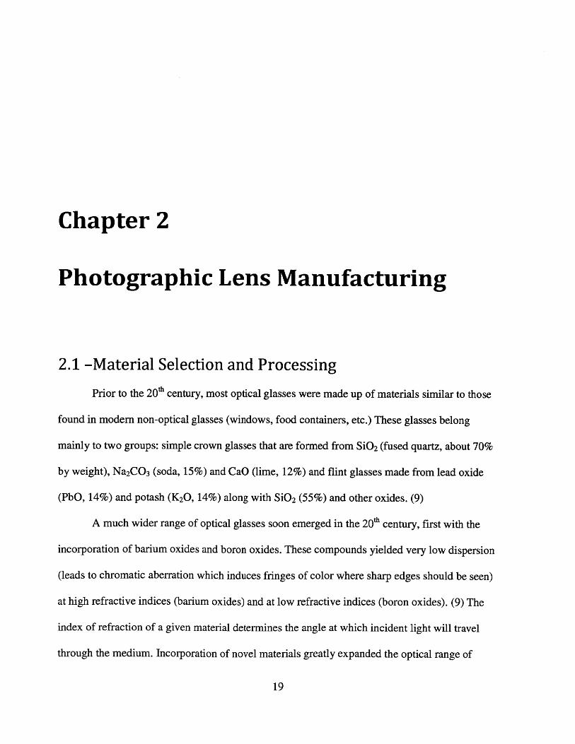
0.5 mm of material with some ranges given the size of the lens as seen in Table 2-1. (12)
Material removal increments for various levels of grinding can be seen in Figure 2-9.
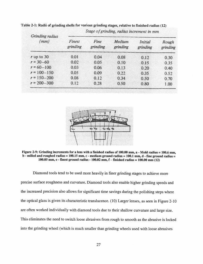
Table 2-1: Radii of grinding shells for various grinding stages, relative to finished radius (12)
Stage ofgrinding, radius increment in mmGrinding radius
(mm) Finest Fine Medium Initial Roughgrinding grinding grinding grinding grinding
r up to 30 0.01 0.04 0.08 0.12 0.30r = 30-60 0.02 0.05 0.10 0,15 0.35r =60-100 0.03 0.06 0.13 0.20 0.40r =100-150 0.05 0.09 0.22 0.35 0.52r - 150-200 0.08 0.12 0.34 0,50 0.70r 200-300 0.12 0.28 0.50 0.80 1.00
Figure 2-9: Grinding increments for a lens with a finished radius of 100.00 mm, a - Mold radius = 100.6 mm,b - milled and roughed radius = 100.15 mm, c - medium ground radius = 100.1 mm, d - fine ground radius =
100.05 mm, e - finest ground radius - 100.02 mm, f - finished radius = 100.00 mm (12)
Diamond tools tend to be used more heavily in finer grinding stages to achieve more
precise surface roughness and curvature. Diamond tools also enable higher grinding speeds and
the increased precision also allows for significant time savings during the polishing steps where
the optical glass is given its characteristic translucence. (10) Larger lenses, as seen in Figure 2-10
are often worked individually with diamond tools due to their shallow curvature and large size.
This eliminates the need to switch loose abrasives from rough to smooth as the abrasive is locked
into the grinding wheel (which is much smaller than grinding wheels used with loose abrasives

to grind sets of lenses). (12) In order to obtain such precise results a radius of curvature accuracy
of ±0.0008 mm is required of the diamond tool. (12)
Figure 2-10: Fine grinding of lenses (gray disks) with precision diamond grinding tools (white) (10)
After fine grinding, glass lenses are polished to achieve their characteristic transparency.
Polishing removes visible machining marks left over from previous processes using a similar
setup as fine grinding. Lenses are polished until the surface roughness has been reduced to a
characteristic length on the order of a sub-micron. (10) A cast iron shell, similar to a grinding
wheel is use to house the layer of polishing pitch that polishes the lenses. On the surface of the
polishing pitch is a layer of polishing rouge (usually cerium oxide) mixed with water and it is
this rouge that physically polishes the lenses. (12) This polishing pitch is very similar to the pitch
described above that is used to fix lenses onto a block holder for rough grinding processes. (12)
Since polishing removes very little material per unit time relative to grinding operation,
adjustments for thickness are either negligible or on the order of 0.01 micron or less for precision

lenses. (12) Polishing is typically carried out with a constant stream of lubricant, typically water,
that removes the heat generated from the friction of the polishing rouge on the glass. This heat
could potentially warm the polishing pitch or the lens-fixing pitch and induce errors in the lens
geometry. (12) After both sides of the lenses are polished and removed from the block, they are
thoroughly cleaned with solvent that removes any debris (pitch, cement, etc.) from the surfaces
of the lens. Use of automated ultrasonic machines can help to ensure cleanliness in this process.
(12)
Once lenses have been made transparent, they can be inspected once again before
finishing processes are performed. The precision of the critical dimensions of the lens is
measured using lasers and based on the observed fringe patterns the lenses are either passed onto
the next stage or sent back into whatever machining processes are needed. (10) Lenses are
checked for cosmetic appearance and striae, or undesired visible streak lines, as well as for
thickness, centring accuracy (addressed in the next paragraph), surface accuracy and imaging
quality. (12) Some cosmetic defects are permissible and are dependent on the position of the
optical component as well as the size of the defect. The closer the component is to the image
plane, the more scrutiny it must bear to pass inspection. Otherwise, as long as the blemish does
not affect image quality or it cannot be seen easily it may not be remedied. This of course
depends on the reputability and quality standards of the manufacturer and the lens brand. (12)
After passing inspection, lenses must be adjusted such that their mechanical axis (axis of
the outer cylindrical edge) and optical axis are coincident as seen in Figure 2-11. This process is
called centring and is seen in Figure 2-12. The element is first aligned on a centring device such
that its optical axis is exactly perpendicular to the cutting surface. (3) This device typically uses
lasers or some form of transmitted light to find the lens' optical center. The edges are then

ground to a specified diameter. Lenses with larger radii of curvature require more attention to
ensure proper alignment, as seen in Figure 2-13. (12) The edges are typically ground using a
rough grinding wheel as optical transparency of the edges is unnecessary. Some lenses may also
be given a chamfer at the point where the cylindrical edges meet the edges of the lens' spherical
surface. This chamfer is used to provide a flat surface for the lens when in contact with other
parts in the final assembly. (12)
Figure 2-11: Lens decentration, a - axial displacement centring error, b - optical axis,c - axis of the outer edge (12)

Figure 2-13: Centring of an optical lens in between brass chucks shortly before edge grinding. The operatorcenters the lens using a microscope (not seen). (10)
0.150.140.130.120.11
4z0. 10
e 0.09S0.08g
0.070.060.05
e 0.03S0.02
S 0 02 0.04 0.06 a.08 0.10 012 0.14 0.1 08 0.2 0.22 0.24 0.26 028Axial displcment * centring acctrcy (mm) ,
Figure 2-12: Centring accuracy that can be achieved by optical methods depending on the sum of lens surfacecurvatures (1/r1 + 1/r2) with concave radii having a negative sign (12)

2.3 - Finishing Processes and Assembly
After lenses pass through quality-control inspection they are then ready for finishing
operations which include another cleaning cycle and the application of an anti-reflective film
coating. The lenses are thoroughly washed in an ultrasonic washer in large batches and placed
inside a large vacuum evaporator, seen in Figure 2-14 for the application of the film coating.
Proper cleaning and evacuation ensures atmospheric debris such as dust does not get coated onto
the optical lens. (12) Brushes with radioactive elements can also be used to remove any
electrostatic charge from the lens surface. While evacuation is occurring, the optical surfaces are
again cleaned by a glow discharge in the vacuum chamber bombards the lenses with cleansing
molecules. (12)
Figure 2-14: Vacuum evaporator with optical lenses awaiting cleaning and coating (10)

Anti-reflection (AR) coatings are critical for maximizing transmission of incident light as
an untreated glass substrate will reflect 4% of incoming light at both interfaces. An anti-
reflection coating will help to prevent ghost images which form as a result of reflections of light
traveling in the wrong direction. An AR coating can reduce light reflectance by 70 percent or
more. (14) The coating must be an odd number of quarter wavelengths (approximately 125
nanometers) such that any incoming light rays that reflect off the coating and the light rays that
reflect off the outer glass surface undergo destructive interference since their phase difference is
one-half wavelength, as seen in Figure 2-15. (14) Because each coating is tuned to eliminate a
specific wavelength, many modem lenses utilize multiple coatings which reduce reflection over
wide chromatic bands. (12)
AirpaThickness, t
OpficcJ Thkkness = o I
Thin Film V
/j, / V/ /_V
Figure 2-15: Anti-reflection coating inducing destructive interference in reflected light rays (14)
The anti-reflection coating is made of magnesium fluoride (MgF2) which is evaporated
onto the lens surface while they are heated to 300*C. (12) MgF2 is evaporated from molybdenum
boats as a white powder and deposited on the surface of the lenses and the deposition thickness is
monitored by watching the characteristic color of a reflection with a spectrophotometric detector.

(12) The anti-reflection coating also serves the purpose of protecting the glass surface of the lens
against stain formation and other irregularities. (12)
After application of protective coatings, various glass lenses are brought together to form
lens systems, as seen in Figure 2-16. Most modem photographic lenses, as seen in Figure 2-17
are made from several individual lenses. Assembly is almost always completed by hand, as seen
in Figure 2-18 as the sensitive nature of lens alignment requires deliberate attention and the
handling of lens components must be such that the utmost care is given in order to prevent
damage of individual glass lenses. (10)
Figure 2-16: Canon EF 500mm f4L IS II USM Telephoto Lens. Telephoto lenses such as this are often madeof many lenses, 10 or more, and thus require meticulous assembly. (Cost = $7,000) (15)

Figure 2-17: Cross-sectional view of the lens seen in Figure 2-16. The inclusion of more lens elementsincreases assembly costs significantly. (10)
Figure 2-18: Glass lenses are assembled into a lens barrel with protective gloves to minimize transfer of skinoils and other debris. (10)
Following a pre-assembly cleaning, individual glass lenses are mounted in lens barrels or
sub-barrels, depending on the complexity of the lens system as seen in Figure 2-19. (10) Lenses
are mechanically set into place using threaded retaining rings and the use of adhesive cement on
the outer cylindrical edge is used to hold individual lenses in place. (10)

Figure 2-19: Final assembly of the two sub-barrel assemblies of the Canon EF 500 mm lens seen in Figure 2-16.(10)
Many lens systems also require the cementing of individual glass lenses together with
other lenses. This procedure is extremely delicate and is carried out in a dust-free room. (12) The
lenses are cleaned right before application of the cement and joining. Lenses that are joined
typically bring together a concave and convex lens; the concave lens is heated to the melting
point of balsam - the cement to be used. (12) The concave lens is then held-adhesive side down
to prevent dust collection and the balsam is spread over the surface. This process is repeated for
the convex conjugate lens to be cemented; meanwhile the concave lens sits in a glass jar to
protect from dust. The lenses are then brought together and compressed to squeeze out excess
cement as well as air bubbles. The pressing is done in an oval-rotational pattern such the bubbles
migrate out from the center of the lens. (12) Before the cement cools and hardens, the lenses
must be aligned. Alignment can be done mechanically, making the outer cylindrical edges
concentric using a V-block or optically, through methods similar to optical centring describe
above in Section 2.2. (12) Optical alignment is superior in that it bypasses any errors associated
with aligned mechanical/optical axes, as seen in Figure 2-20. (12)

4
Figure 2-20: Potential centering error within a optical system as a result of unequal lens diameters, a -Centring error within the system, b - optical axis of the convex lens, c - optical axis of the flint lens, d -
diameter difference between the lenses. (12)
Once the internal lens-bearing components have been assembled together and inspected,
exterior structural and ergonomic components are fitted on the outside of the barrel assembly, as
seen in Figure 2-21. Other electronic and measurement devices are incorporated into the lens
assembly including focusing indicators, focusing motors, focusing rings and image stabilization
components.
Figure 2-21: Addition of exterior components to the lens barrel assembly (10)
37

After final assembly of all features, the lens is put through a final inspection before
packaging and distribution. Optical and electronic components of the photographic lens are
comprehensively inspected for performance and for the existence of optical deformities
including intra-barrel dust and other debris. (12) Testing is mainly divided into two forms: axial
ray testing and oblique ray testing. Axial ray testing involves imaging of a pin-holed collimator
or a test object that can only appear sharp in the case that all photographic lenses are aligned
optically as seen in Figure 2-22. (12) Oblique ray testing involves use of mirror to test for optical
clarity through non-centered portions of the lens system. (12) Much non-adequate imaging arises
from centering errors between different lenses in complicated mechanical assemblies. Such
errors can be corrected by shifting only one lens component but the most efficient way to deal
with such errors is to avoid them through meticulous assembly procedures and extremely precise
tolerances. (12) Nevertheless, optical performance variation between lenses with the exact same
design specification is often observed, especially in low-cost zoom lenses. (3)
8
C4-/
Figure 2-22: Testing a completed optical system for axial imagery, a - Centering collet for mounting the lensto be tested, b - collimator objective, c - illumination for the collimator graticule, d - collimator graticule or
pin hole, e - rotating ground glass disc, f - observation microscope, g - lens under test (completephotographic objective) (12)

Chapter 3
Technological Advances in Grinding
3.1 - Physics of Grinding
Grinding is an abrasive process that utilizes the characteristic roughness of the abrasive
surface to gradually wear another surface to a specified dimension. Grinding is technically a
cutting process in which relatively small individual grains cut into the working material and
remove chip through a shearing process. (16) Unlike machining, grinding utilizes abrasive grains
with irregular shapes that are randomly distributed along the tool surface. The rake angle is
highly negative, as seen in Figure 3-1, such that chips undergo a great deal of plastic deformation
before removal. For glass lenses, surface speeds tend to be much lower than for metals owing to
the brittleness of the glass. (16)

Figure 3-1: Schematic of chip formatio by an abrasive grain with a wear flat. The rake angle (angle betweengrain and chip) is highly negative and the shear angle is very shallow. These parameters would make cutting
difficult if the material removal rate weren't so low. (16)
Grinding, when controlled geometrically with use of precise tools and dynamically
through constant application of force, can produce very smooth finishes with surface
roughnesses on the order of nanometers (much less than the wavelength of light). (16) Grinding
typically serves to remove very hard and/or brittle material that cannot be accomplished with
ordinary machining and to provide excellent dimensional tolerance and/or surface finished for
precision parts. (16)
For glasses, rough and fine grinding operations are typically carried out at slow surface
speeds and depths of cut to prevent cracking and the formation of residual stresses. During finer
grinding operations, a process known as lapping is used to give lenses their characteristic
transparency and lustrous surface finish. (16) Lapping is a type of grinding where the abrasive is
loose and not adhered to the grinding tool itself. The abrasive are typically introduced as a slurry
(referred to as polishing rouge in Section 2.2) The tool, known as a lap, is made to conform to
the surface of the lens, minus the diameter of the abrasive grains. Because the tool is smooth, its
dimensions can be more precisely controlled and as long as the abrasive can be controlled too,
excellent surface finish is attainable. (16)

3.2 - Commercial Advances in Grinding Technology
-ances in ontical production. circa 1988 (3)
Refractive index of glass ± 0.001Abbe's Number +0.2Element thickness ±0.010 mmElement curvature ±0.030 mmElement centring ± 0.004 mmSpacing of elements ± 0.003 - 0.007 mmAverage surface roughness ± 0.1 - 0.03 pin
The essence of lens manufacturing as described in Chapter 2 has remained the same for
the preceding 30 years. Many modifications have been made to save time, increased production
rate and more precisely control machining and inspection operations. Unfortunately, many of
these advances, especially those of the past decade are not readily available in textual or
electronic sources due to proprietary concerns of major lens manufacturers (Canon, Nikon, Carl
Zeiss, etc.). To properly gauge the advances in commercial production requires more intimate
understanding than is allowed for sources such as Canon's Virtual Lens Plant (cited throughout
this paper). Such understanding must be gained through extensive knowledge of the industry as
well as access to lens manufacturing plants and the nature of the technology located therein.
Unfortunately, such access is beyond the scope of this paper but a presentation of some past
patents will hopefully shed light on what sort of technologies lens manufacturers are developing.
The values given for typical tolerances above in Table 3-1 help to give a sense of the absolute
precision of lens manufacturing.
Canon has several issued patents in the United States pertaining to lens manufacturing.
Three in particular pertain to the grinding/polishing process. The first, (17) describes a novel
procedure for polishing and grinding optical components. The novelty is not in the grinding
42

process but rather in the transfer of components from a conveying position to a working position.
This machine is likely utilized in mid to high-volume applications where automation is necessary
for lowering costs. The apparatus, seen in Figure 3-2, uses air pressurization to convey lens to a
spherical grinding tool for grinding/polishing procedures.
Figure 3-2: Canon's grinding and polishing apparatus used to convey and grind spherical lenses throughautomation (17)
Aside from lowering handling costs, Canon has also sought to reduce the number of
grinding operations lenses must undergo and the time these steps take. Canon has developed a
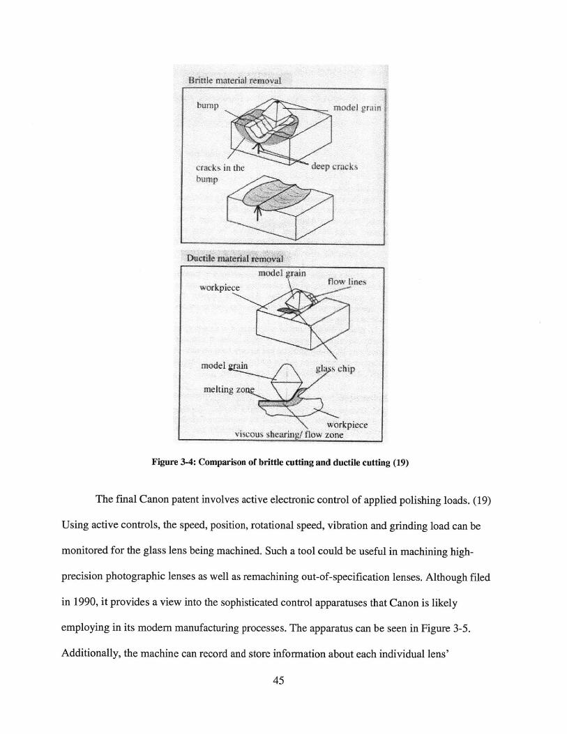
grinding method that allows for more regulated grinding of brittle materials. (18) By prescribing
a proper applied load and depth of cut with an abrasive grinding wheel, this apparatus can cut
into the glass in a manner that resembles ductile machining instead of brittle machining. The
machine is really no different than a typical grinding apparatus except in its ability to maintain a

sub-critical load and stay in the ductile cutting region. Typically, grinding is carried out in the
brittle regime with higher loads and deeper cuts that result in cracking or chipping on the surface
of the glass. Ductile-regime cutting maintains a sufficiently small cutting depth and load as well
as having the abrasive grains on the grinding tool trued (machined and smoothed to a precise
roughness). Brittle and ductile-regime cutting are shown below in Figures 3-3 and 3-4. Being
able to use ductile-regime cutting can allow for significantly more smoothing in a single grinding
operation than is normally attained on a conventional brittle-cutting grinding tool. (18)
Figure 3-3: (left) Brittle cutting with abrasive grains cutting beyond the critical depth (right) ductile cuttingwith abrasive grains cutting short of the critical depth (18)
Briut material removal
Ductile mwial ieliff
model grain
workpiece
model gy
mneking zont \,
Figure 3-4: Comparison of brittle cutting and ductile cutting (19)
The final Canon patent involves active electronic control of applied polishing loads. (19)
Using active controls, the speed, position, rotational speed, vibration and grinding load can be
monitored for the glass lens being machined. Such a tool could be useful in machining high-
precision photographic lenses as well as remachining out-of-specification lenses. Although filed
in 1990, it provides a view into the sophisticated control apparatuses that Canon is likely
employing in its modem manufacturing processes. The apparatus can be seen in Figure 3-5.
Additionally, the machine can record and store information about each individual lens'
45
bump
model griin
cracks
\ workpieceviscous shearing/ flow zone
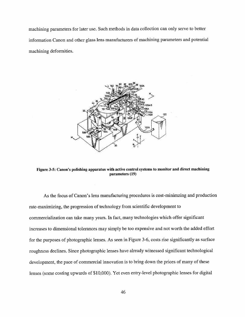
machining parameters for later use. Such methods in data collection can only serve to better
information Canon and other glass lens manufacturers of machining parameters and potential
machining deformities.
Figure 3-5: Canon's polishing apparatus with active control systems to monitor and direct machiningparameters (19)
As the focus of Canon's lens manufacturing procedures is cost-minimzing and production
rate-maximizing, the progression of technology from scientific development to
commercialization can take many years. In fact, many technologies which offer significant
increases to dimensional tolerances may simply be too expensive and not worth the added effort
for the purposes of photographic lenses. As seen in Figure 3-6, costs rise significantly as surface
roughness declines. Since photographic lenses have already witnessed significant technological
development, the pace of commercial innovation is to bring down the prices of many of these
lenses (some costing upwards of $10,000). Yet even entry-level photographic lenses for digital
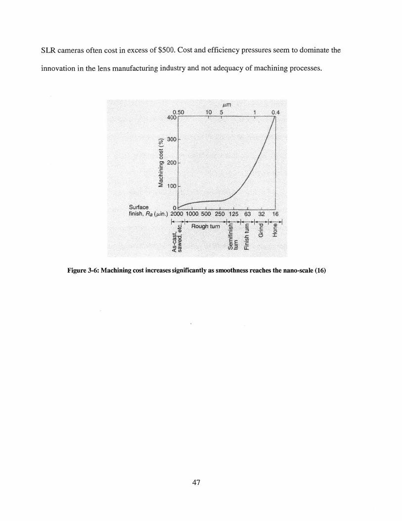
SLR cameras often cost in excess of $500. Cost and efficiency pressures seem to dominate the
innovation in the lens manufacturing industry and not adequacy of machining processes.
0.50400 r
C
Surfacefinish, Ra (4in.)
An
10 5 1 04
2000 1000 500 250 125 63 32 16
2 Rough tum E
E Ej>a
Figure 3-6: Machining cost increases significantly as smoothness reaches the nano-scale (16)

3.3 - Scientific Advances in Grinding Technology
The progress of optical engineering and manufacturing technologies has allowed for
optical engineers and makers of precision components to utilize a wide range of new optical
tools. Through effective new means of tool design, tool compensation and novel finishing
methods the grinding apparatuses of the future may break away from machines in conventional
use. Also, new methods in aspheric lens manufacturing may enable a whole new class of
conformational optical glass lenses.
Aspherical lenses are showing promise in scientific applications as grinding technologies
have improved and are capable of being controlled to such a degree that deterministic spherical
lenses no longer limit optical instruments to confined geometries. Photographic objectives still
rely heavily on spherical lenses as their ease of production and general adequacy doesn't provide
sufficient incentive to invest heavily in developing commercially viable aspherics. These non-
spherical optics will also include non-axisymmetric lenses for specialized purposes. (20)
Studies of tool design and glass machining parameters have led researchers to find
optimum conditions for grinding and polishing optical glass lenses. Application of CNC
machines as well as tool path compensation methods have been researched and have shown to
increase profile accuracy and decrease surface roughness by 50%. Surface roughnesses, even for
aspheric lenses, have been pushed down to the single nanometer scale - well below the
wavelength of visible light. (20) Optimization of machining parameters (work spindle speed,
wheel spindle speed, federate, etc.) have been tested out in recent years with different machining
forms (parallel grinding, cross grinding) to minimize final surface roughness. (21)
Experimentation with new tool derivatives has led to interesting and beneficial results.
High-frequency surface irregularities are common problems in aspheric lens production with
48

rigid tools. A study done with a semi-flexible multiple-segment ring tool, seen in Figure 3-7, was
proven to eliminate such irregularities and produce optically consistent transmission patterns.
(22)
Figure 3-7: Semi-rigid tooling applied to grinding (24)
Theoretical inquiries into integrated manufacturing systems for freeform optics have risen
as a computational and theoretical means of avoiding costly trial-and-error optimization
experiments, seen schematically in Figure 3-8. Such systems not only depend on precision of
machine tools but also depend on advanced optics design, modeling, data collection and
optimization of the machining process. Such systems claim to shorten development cycle time
and provide means for determining final surface roughness and optimal cutting strategy. (23)
Results from such proposed systems are promising with predicted values giving final surface
roughnesses about 1-6 nanometers away from measured values at surface roughnesses of about 2
nanometers as seen in Figure 3-9. (23)
Figure 3-8: Schematic of predictive model used to estimate lens surface characteristics (23)
E 2 - Predicted valueMeasured valu
10CD)
a)
6
4E 21
0
1000 1500 2000 2500 3000 3500 4000 4500 5000
Spindle Speed (rpm)
Figure 3-9: Predicted and measured values for fmal surface roughness as a function of spindle speed (23)
Technological gains are also being made in sensor feedback networks to rectify undesired
shifts in machining parameters in order to maintain precision. Computer-aided machining
(CAM) systems with error compensation, on-machine measurement and simulation capabilities
have realized gains in accuracy for machining processes. For example, a CAM system developed
at Xiamen University in China halved the surface form error of a half-meter diameter aspheric
lens from 8.2 to 4.1 microns. (24) Such a system was able to supply high-precision grinding

control for planar, inclined planar, spherical, axisymmetric aspherical, non-axisymmetric
aspherical and off-axis aspherical surfaces. (24)
The friction associated with the grinding process can build up sufficient heat to affect
dimensional stability of the workpiece. Studies into the application of ventilation helped to shed
light on thermal drift as well as inquiries into temperature changes from human handling and
whether or not cutting fluid should be applied as a mist or as a drip. (25) Models derived from
the results of these experiments were the ultimate goal of the researchers. (25) Such parameters
are especially important where multiple passes with different tools are required to cut given
geometry features. Such parameters for a laboratory setting, including maximum deviation
results are shown in Table 3-2.
Table 3-2: Peak-to-valley errors induced as a result of thermally-significant parameters (25)PV PV
radial axial(Um) (pim)
Machine door Open 0.2 0.3
Closed 0.1 01
Laboratory door Open 0.05 0.20
Closed 0.05 0.25
OMS mist No spray mist 0.2 0.3
Spray mist on 0.5 0.9
Mist air only Air off 0.2 0.05
Air enabled 0.5 0.1
OMS droplets No OMS 0.2 0.2
OMS dripping 0.2 0.3

In addition to optimizing standard grinding procedures the inclusion of novel grinding
and polishing operations may have potential as alternative methods with different sets of
advantages and drawbacks. Fluid-jet polishing (FJP) is showing promise as a way of removing
very small amounts of material (as little as 1 nm/min) from brittle materials including optical
glass. (26) FJP utilizes a low-pressure water jet with a given concentration of abrasives that is
used to alter a glass surface in a predictable fashion. (26) FJP also avoids tool wear, workpiece
cooling times and debris removal procedures. The FJP process can achieve very low surface
roughness when used to cut a uniform channel in glass - an average surface roughness of 1.2 nm.
Such roughness can be achieved since the FJP process removes material in the ductile regime
and avoid the cracking and chipping that is characteristic of brittle grinding. (26) The depth of
the FJP is generally accurate to about 5% but the degree with which this technology can be
scaled still remains to be seen.
Another mode of fluid polishing holds even more promise: magnetorheological finishing
(MRF). MRF utilizes the relative motion of an electromagnet, the magnetic polishing fluid and
the workpiece. The magnet generates a non-uniform magnetic field that passes through the
workpiece and polishing fluid. The magnetic field increases the viscosity of the polishing fluid as
it passes through a flow constriction formed between the lens and a moving wall, seen in Figure
3-10. (28) At this moment, the fluid acts to grind away materials from the workpiece. Thus, a
large grinding tool is unnecessary, tool grinding is avoided and the electro-magnetic nature of the
process is very amendable to digital control. (28) MRF may also be used to finish aspherical
lenses with changing curvature due to its flexibility. (28) Finishing results of MRF show
promise: MRF was able to finish test pieces to within 300 nm of desired shape with a finished
average roughness of 1 nm. (28)

AY polishingspotpart ,
MRP fluid
movinAA~wal
!i~x X
Figure 3-10: MRF with process parameters (28)

Chapter 4
Conclusion
Photographic lens manufacturers have a great multitude of new technologies to select
from in future design iterations of their production systems. While most of these processes may
not at first be cost-effective, integration and optimization of these processes into commercial
production systems will likely yield cost benefits to producers and consumers alike. The
technologies presented here were mere glances of the technical precision and skill required to
develop and implement such advanced processes. Proceeding work should delve into these
technologies with greater detail and analyze which groups of optical devices will most benefit
from their development.
Photographic lenses are marvels of engineering and the appreciation of their intensive
production and rigorous inspection requirements should give all an appreciation for the optical
images they enable.

Bibliography
1. Ellis, Ted. Camera Types. Ted's Photographics. [Online] [Cited: March 28, 2011.]http://www.ted.photographer.org.uk/camera types.htm#hometop.
2. Focal length. Wikipedia. [Online] Wikimedia Foundation, Inc., March 24, 2011. [Cited: March29, 2011.] http://en.wikipedia.org/wiki/Focal length.
3. Ray, Sidney F. Applied Photographic Optics. London & Boston : Focal Press, 1988.
4. VR (Vibration-Reudction). Nikon. [Online] Nikon Corporation, March 2008. [Cited: March29, 2011.]
5. Diaphragm (optics). Wikipedia. [Online] Wikimedia, Inc., February 3, 2011. [Cited: March 29,2011.]
6. Apple, Jennifer. The Photoshop Blog. PhotoshopSupport.com. [Online] October 2006.[Cited: March 29, 2011.]
7. Nice, Karm, Tracy V. Wilson and Gerald Gurevich. How Digital Cameras Work.HowStuffWorks. [Online] Discovery. [Cited: March 29, 2011.]http://electronics.howstuffworks.com/cameras-photography/digital/digital-camera2.htm.
8. Rockwell, Ken. D40 Specifications. Ken Rockwell. [Online] 2006. [Cited: March 29, 2011.]http://www.kenrockwell.com/nikon/d40/d40-specifications.htm.
9. Pfaender, Heinz G. Schott Guide to Glass. London : Chapman & Hall, 1996.
10. Canon Inc. Virtual Lens Plant. Canon Camera Museum. [Online] Canon Inc. [Cited: April 4,2011.] http://www.canon.com/camera-museum/tech/l1plant/main.html.
11. Zarzycki, Jerzy. Glasses and the vitreous state. Cambridge : Cambridge University Press,1982.
12. Zschomuler, Willy. Precision Optical Glassworking. London and Basingstoke : MacmillanPublishers, 1984.
13. How It's Made - Camera Lenses. Discovery Inc.
14. Anti-Reflection (AR) Coatings. Edmund Optics. [Online] Edmund Optics Inc., 2011. [Cited:April 6, 2011.]
15. Carnathan, Brian. Canon EF 500mm f/4.0L IS II USM Lens Review. The Digital Picture.[Online] 2010. [Cited: April 9, 2011.]

16. Kalpakjian, Serope and Steven R. Schmid. The Grinding Process. New York: PrenticeHall, 2010.
17. Yoshinori Murasugi, Akihiko Matoba, Kenji Fujiwara, Toru Imanari.Polishing/Grinding Method. 5,791,972 United States, August 11, 1998. Machine Tools.
18. Takashi Kozakai, Hironori Yamamoto, Nobuo Nakamura, Juji Takashita, ToruImanari. Method and apparatus for grinding brittle materials. 5,573,447 United States ofAmerica, November 12, 1996. Machine tools.
19. Manabu Ando, Nobuo Nakamura, Yoshitane Tsuchiya, Hirotaka Fuse, KazuoWatanabe, Koushi Shinoda. Polishing apparatus. 4.956,944 United States of America,September 18, 1990. Machine tools.
20. The Manufacturing Solution for Harnessing Light in the 21st Century. Pollicove, H.M.Rochester, NY: Trends in Optics and Photonics, 1999, Vol. 24.
21. A Study on Grinding to Improve Profile Accuracy of Aspheric Lens. Baek, S. Y. and Lee, E.S. and J. K. Won. 364-366, Incheon, Korea : Key Engineering Materials, 2007, Vol. OpticsDesign and Precision Manufacturing Technologies.
22. Machinability in Precision Grinding of Aspheric Optical Lens with Diamond Wheel. Baek,S. Y., et al. Incheon, Korea: Key Engineering Materials, 2007, Vols. 364-366.
23. Aspheric optics: smoothing the ripples with semi-flexible tools. Tuell, M.T., Burge, J.H.and Anderson, B. Tucson, Arizona: Optical Engineering, 2002, Vol. 41.
24. An Integrated Manufacturing System for the Design, Fabrication and Measurement of Ultra-Precision Freeform Optics. Kong, L.B., et al. 4, Hong Kong : IEEE Transactions on ElectronicsPackaging Manufacturing, 2010, Vol. 33.
25. A Novel CAM System with X/Y/Z 3-Axis Machines for Large Scale Aspheric Lens Grinding.Deng, Y., et al. 23, Xiamen, China : Applied Mechanics and Materials, 2010, Vols. 37-38.
26. Thermally induced errors in diamond turning of optical structured surfaces. Rakuff, S. andBeaudet, P. 10, s.l. : Optical Engineering, 2007, Vol. 46.
27. Nanometer deep shaping with fluid jet polishing. Booij, S.M., Brug, H. and Braat, J.J.M.Lortzweg, Netherlands : Optical Engineering, 2002, Vol. 41.
28. Precision optics using magnetorheological finishing. Golini, D., et al. Rochester, NY:Trends in Optics and Photonics, 1998, Vol. 24.