photonics - vcephysics.com | the online learning … - vce physics.com photonics • definitions •...
TRANSCRIPT
VCE Physics.comPhotonics -
Photonics
• Definitions
• Why optical fibres?
• Light emitting diodes
• Light dependent resistors
• A light sensing circuit
• Photodiodes
• Phototransistors
• Remote control circuit
• Digital data
• Binary numbers
• Pulse Code Modulation
• Light modulation
2
VCE Physics.comPhotonics -
De!nitions
• Photonics is the area of engineering involving the interactions of light & electronic systems.
• In particular, Photonics forms the basis of modern high-bandwidth communications systems, such as the optical fibre backbone to the NBN or “line of sight” laser based telecommunication systems.
• Optical transducers are devices that convert light energy (& information) into an electrical signal or vice versa. These include laser diodes to create light signals & light dependent resistors / photodiodes / phototransistors to convert light signals back into electrical signals.
• In general, higher amounts of data can be transferred by optical systems, although it needs to be converted back into an electronic form to be used.
3
VCE Physics.comPhotonics -
Why optical !bres?
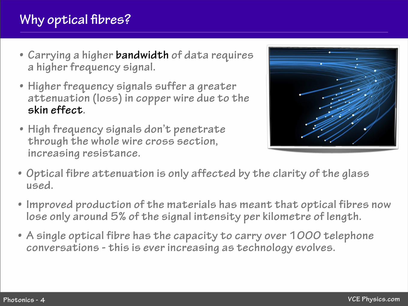
• Carrying a higher bandwidth of data requires a higher frequency signal.
• Higher frequency signals suffer a greater attenuation (loss) in copper wire due to the skin effect.
• High frequency signals don’t penetrate through the whole wire cross section, increasing resistance.
4
• Optical fibre attenuation is only affected by the clarity of the glass used.
• Improved production of the materials has meant that optical fibres now lose only around 5% of the signal intensity per kilometre of length.
• A single optical fibre has the capacity to carry over 1000 telephone conversations - this is ever increasing as technology evolves.
VCE Physics.comPhotonics -
Light emi"ing diodes
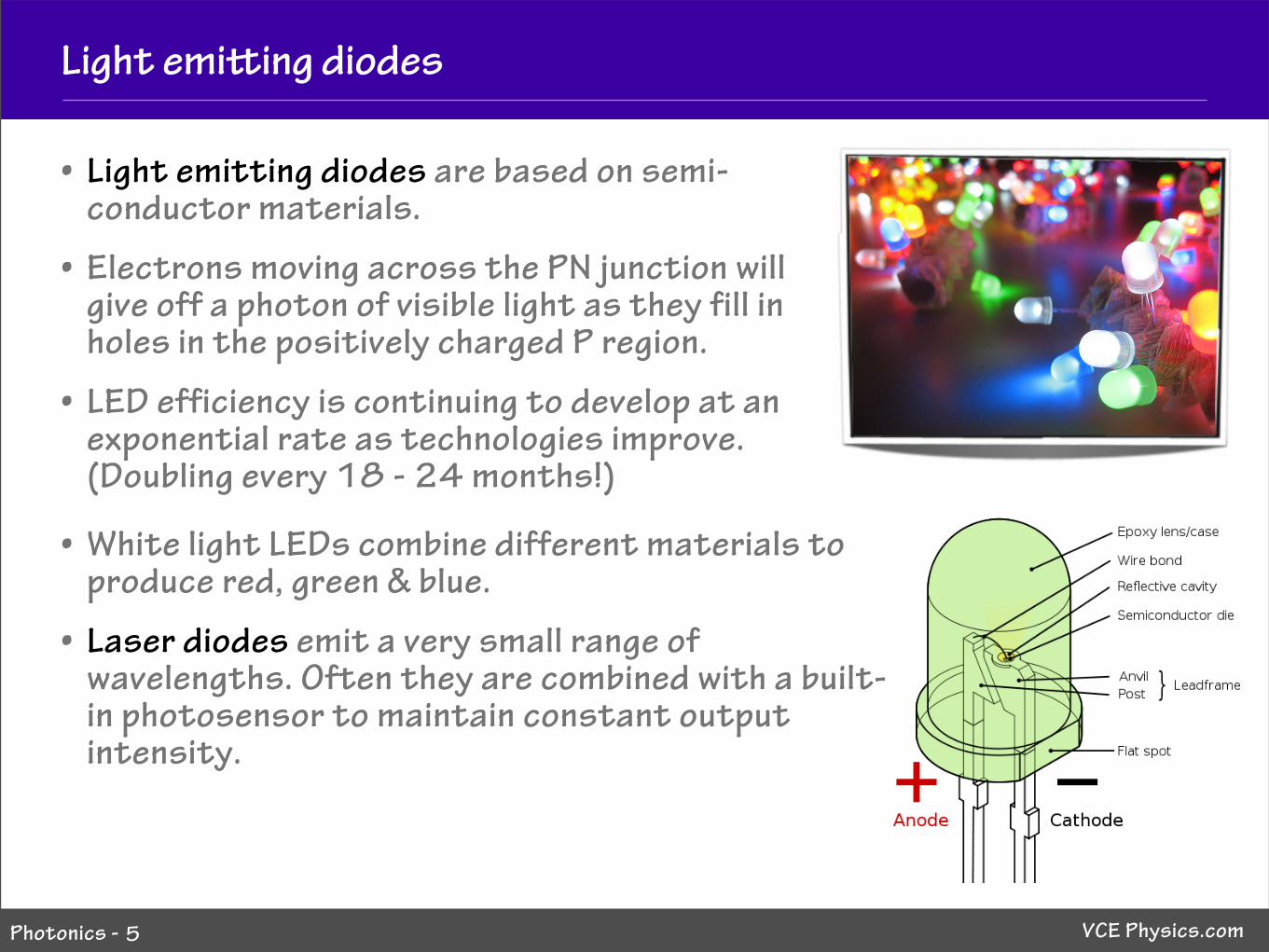
• Light emitting diodes are based on semi-conductor materials.
• Electrons moving across the PN junction will give off a photon of visible light as they fill in holes in the positively charged P region.
• LED efficiency is continuing to develop at an exponential rate as technologies improve. (Doubling every 18 - 24 months!)
5
• White light LEDs combine different materials to produce red, green & blue.
• Laser diodes emit a very small range of wavelengths. Often they are combined with a built-in photosensor to maintain constant output intensity.

VCE Physics.comPhotonics -
Light dependent resistors
• An LDR is made from a material that decreases resistance as the amount of falling on it increases.
• Photons of light absorbed move electrons in the semi-conductor material to higher energy states (closer to ionisation).
• This means that less electrical energy is lost in the material, as these electrons are already closer to being ionised and conducting.
6
http://www.adafruit.com/adablog/wp-content/uploads/2009/05/graph.jpg
More light = less resistance
VCE Physics.comPhotonics -
A light sensing circuit
7
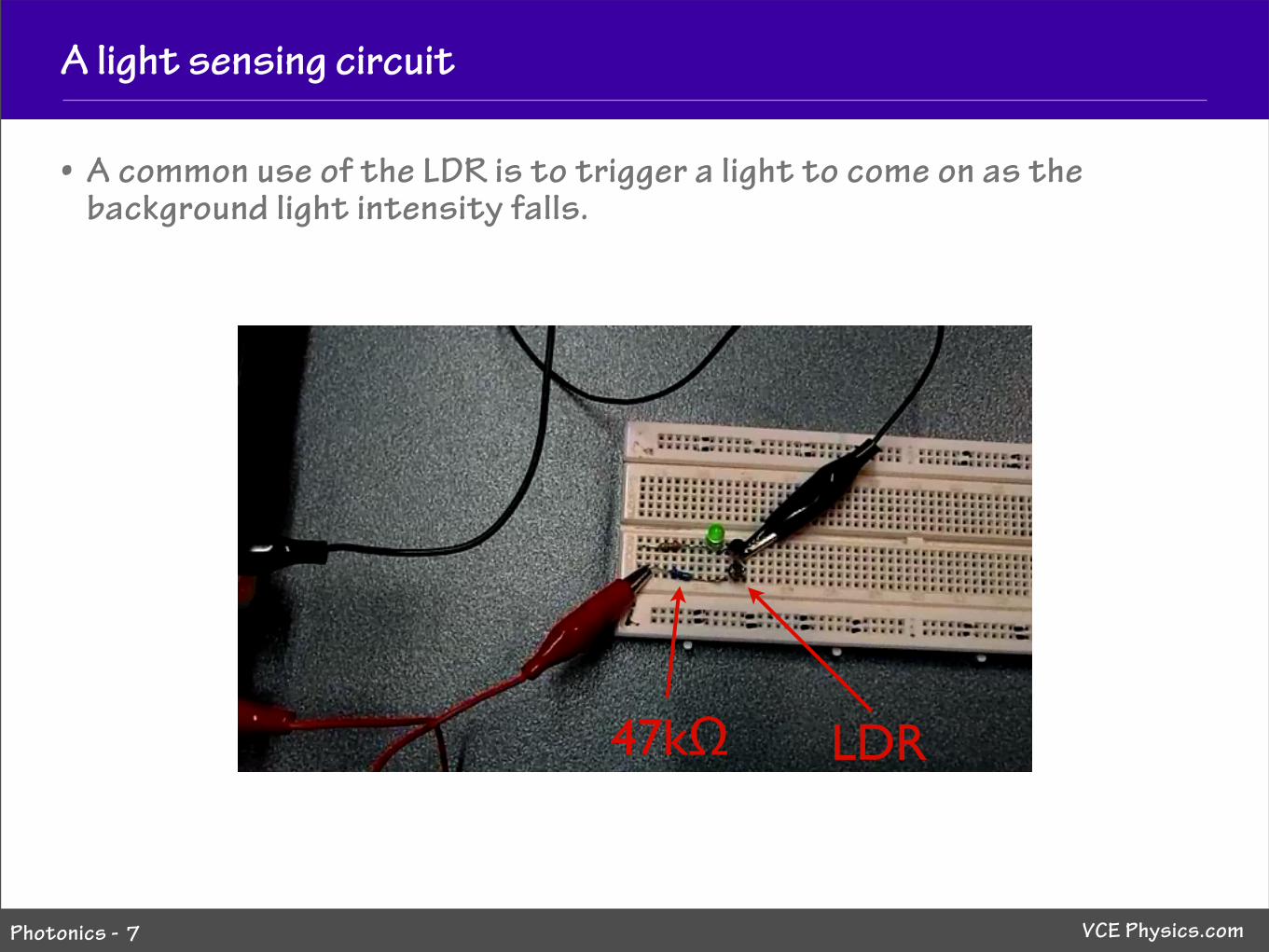
• A common use of the LDR is to trigger a light to come on as the background light intensity falls.
LDR47kΩ

VCE Physics.comPhotonics -
A light sensing circuit
• A common use of the LDR is to trigger a light to come on as the ambient light falls.
8
1. As the light level falls, resistance of the LDR increases.
2. This increases the potential across the LDR (voltage divider) & increases current into the base of the transistor.
3. Increasing the base current into the transistor makes it more conductive and a larger current is drawn from the collector.
4. The LED light gets brighter.
VCE Physics.comPhotonics -
A light sensing circuit
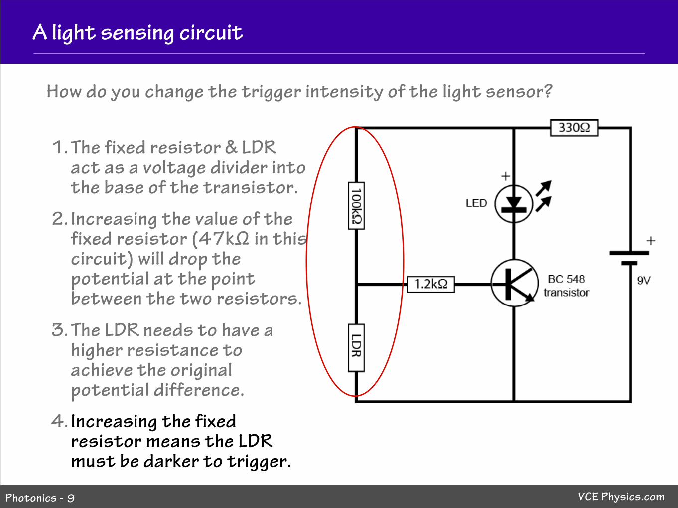
How do you change the trigger intensity of the light sensor?
9
1. The fixed resistor & LDR act as a voltage divider into the base of the transistor.
2. Increasing the value of the fixed resistor (47k# in this circuit) will drop the potential at the point between the two resistors.
3. The LDR needs to have a higher resistance to achieve the original potential difference.
4. Increasing the fixed resistor means the LDR must be darker to trigger.
VCE Physics.comPhotonics -
Photodiodes
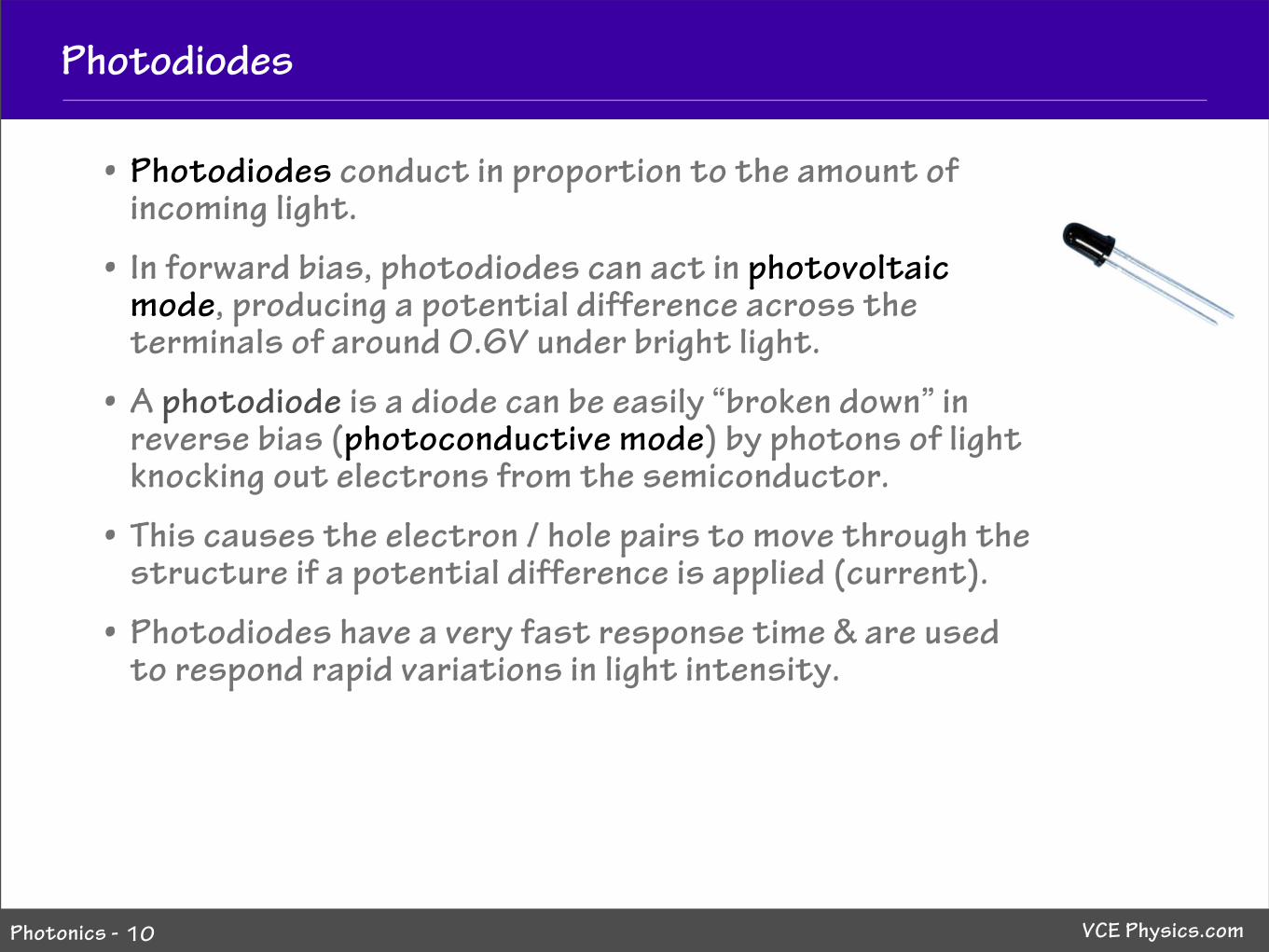
• Photodiodes conduct in proportion to the amount of incoming light.
• In forward bias, photodiodes can act in photovoltaic mode, producing a potential difference across the terminals of around 0.6V under bright light.
• A photodiode is a diode can be easily “broken down” in reverse bias (photoconductive mode) by photons of light knocking out electrons from the semiconductor.
• This causes the electron / hole pairs to move through the structure if a potential difference is applied (current).
• Photodiodes have a very fast response time & are used to respond rapid variations in light intensity.
10
VCE Physics.comPhotonics -
Photodiodes
11
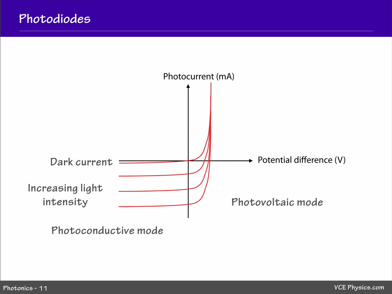
Photocurrent (mA)
Potential di!erence (V)Dark current
Photovoltaic mode
Photoconductive mode
Increasing lightintensity
VCE Physics.comPhotonics -
Phototransistors
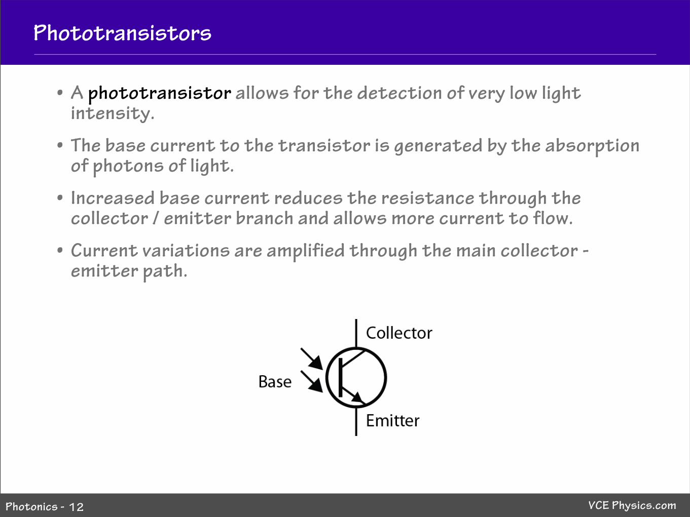
• A phototransistor allows for the detection of very low light intensity.
• The base current to the transistor is generated by the absorption of photons of light.
• Increased base current reduces the resistance through the collector / emitter branch and allows more current to flow.
• Current variations are amplified through the main collector - emitter path.
12
VCE Physics.comPhotonics -
Remote control circuit
13
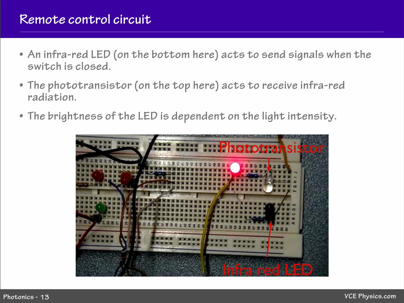
• An infra-red LED (on the bottom here) acts to send signals when the switch is closed.
• The phototransistor (on the top here) acts to receive infra-red radiation.
• The brightness of the LED is dependent on the light intensity.
Phototransistor
Infra red LED
VCE Physics.comPhotonics -
Remote control circuit
14
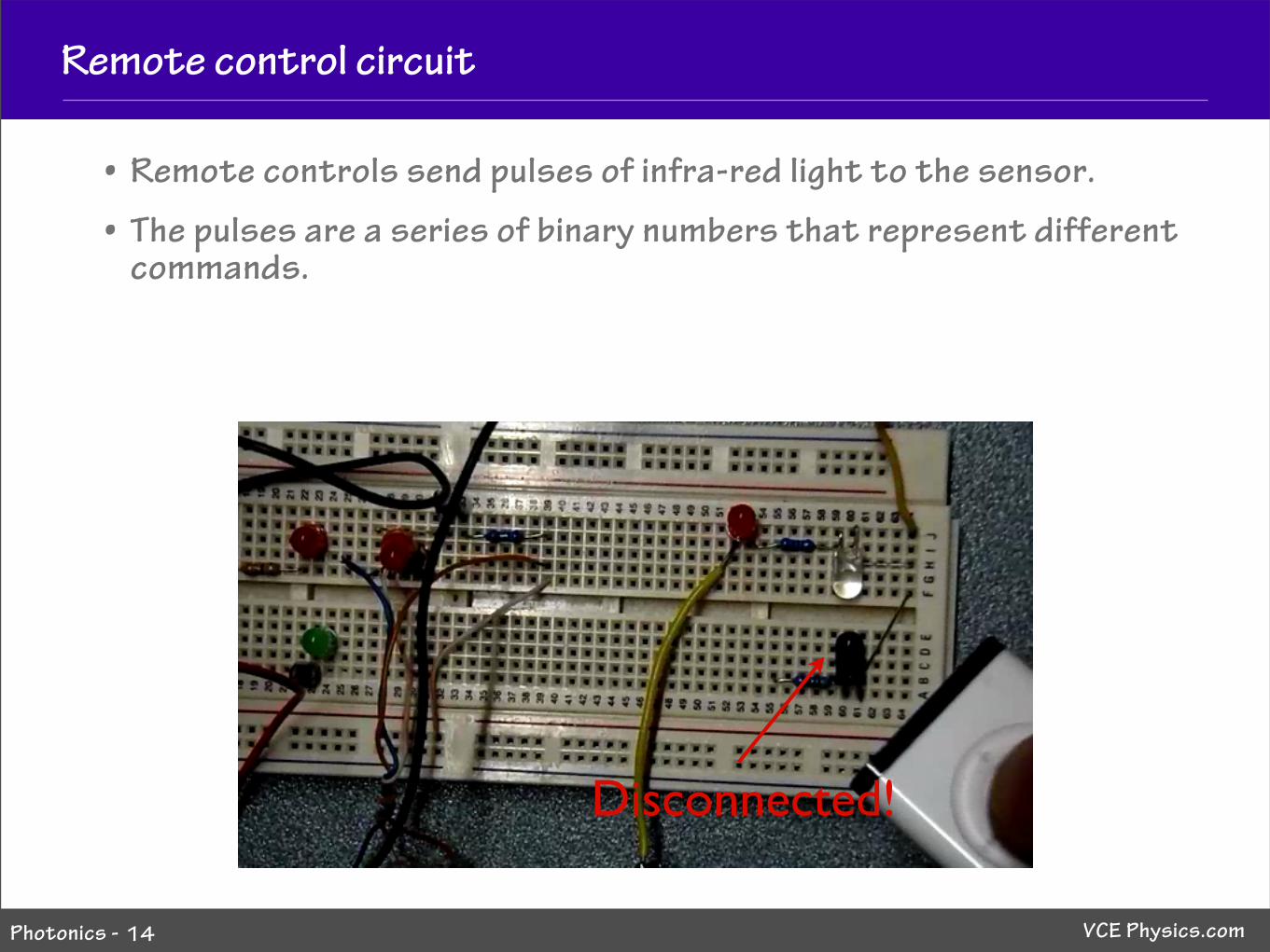
• Remote controls send pulses of infra-red light to the sensor.
• The pulses are a series of binary numbers that represent different commands.
Disconnected!
VCE Physics.comPhotonics -
Remote control circuit
15
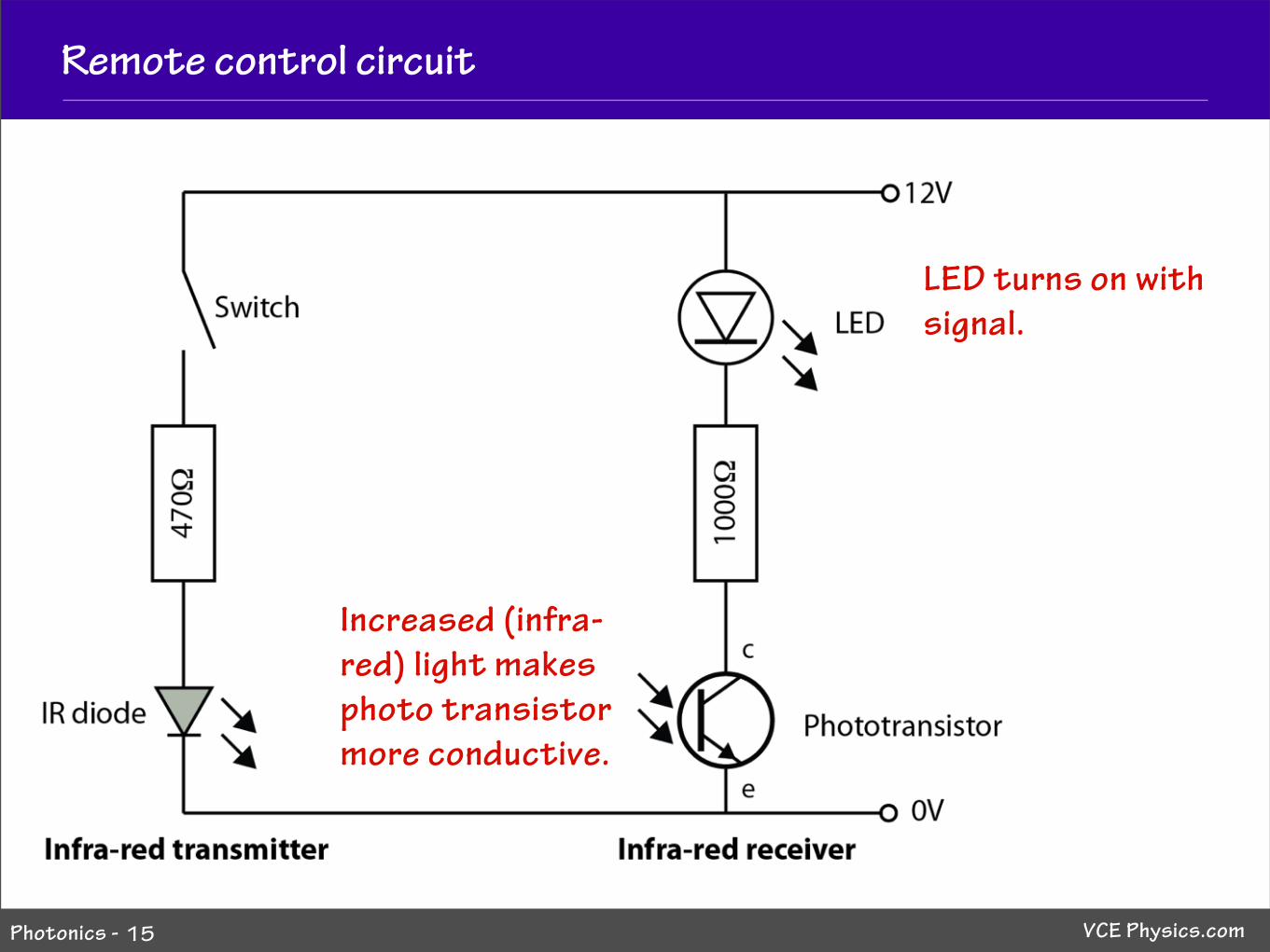
Increased (infra-red) light makes photo transistor more conductive.
LED turns on with signal.
VCE Physics.comPhotonics -
Digital data
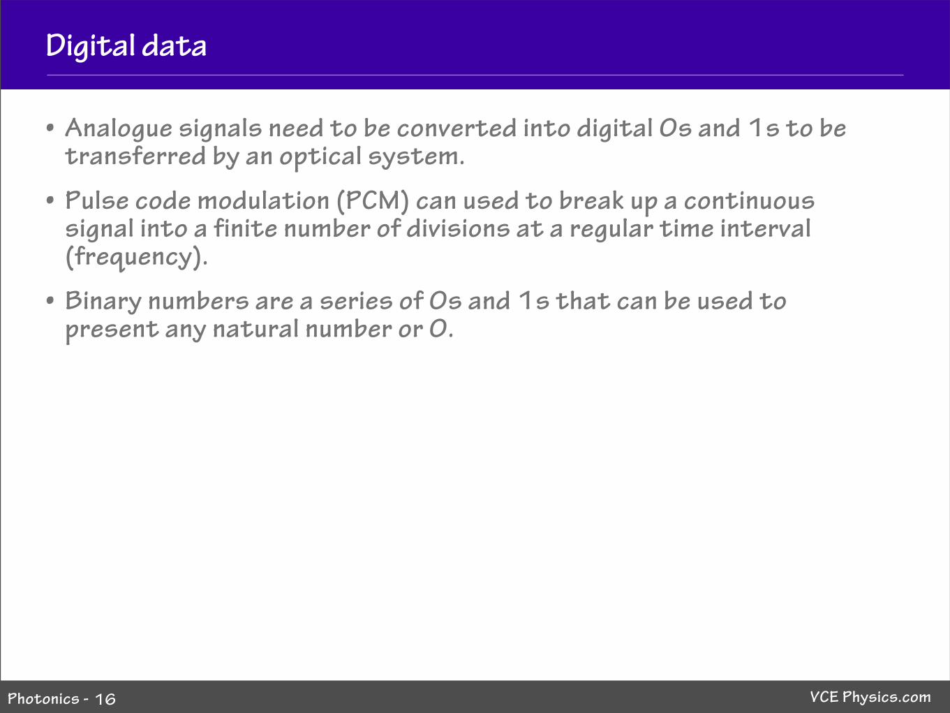
• Analogue signals need to be converted into digital 0s and 1s to be transferred by an optical system.
• Pulse code modulation (PCM) can used to break up a continuous signal into a finite number of divisions at a regular time interval (frequency).
• Binary numbers are a series of 0s and 1s that can be used to present any natural number or 0.
16
VCE Physics.comPhotonics -
Binary numbers
17
8 4 2 1
23 22 21 20
0 0 0 0 0
1 0 0 0 1
2 0 0 1 0
3 0 0 1 1
4 0 1 0 0
5 0 1 0 1
6 0 1 1 0
7 0 1 1 1
8 1 0 0 0
9 1 0 0 1
10 1 0 1 0
11 1 0 1 1
12 1 1 0 0
13 1 1 0 1
14 1 1 1 0
15 1 1 1 1
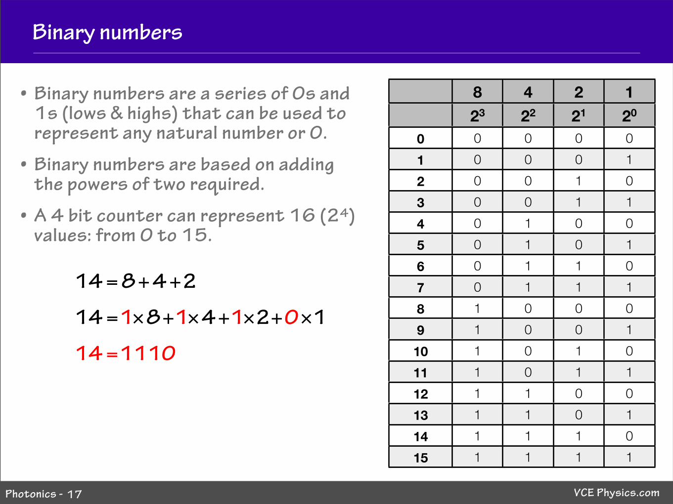
14=8+4+2
14=1!8+1!4+1!2+0!1
• Binary numbers are a series of 0s and 1s (lows & highs) that can be used to represent any natural number or 0.
• Binary numbers are based on adding the powers of two required.
• A 4 bit counter can represent 16 (24) values: from 0 to 15.
14=1110
VCE Physics.comPhotonics -
Pulse code modulation
18
Intensity
Time
0
1
2
3
4
5
6
7
8
9
10
11
12
13
14
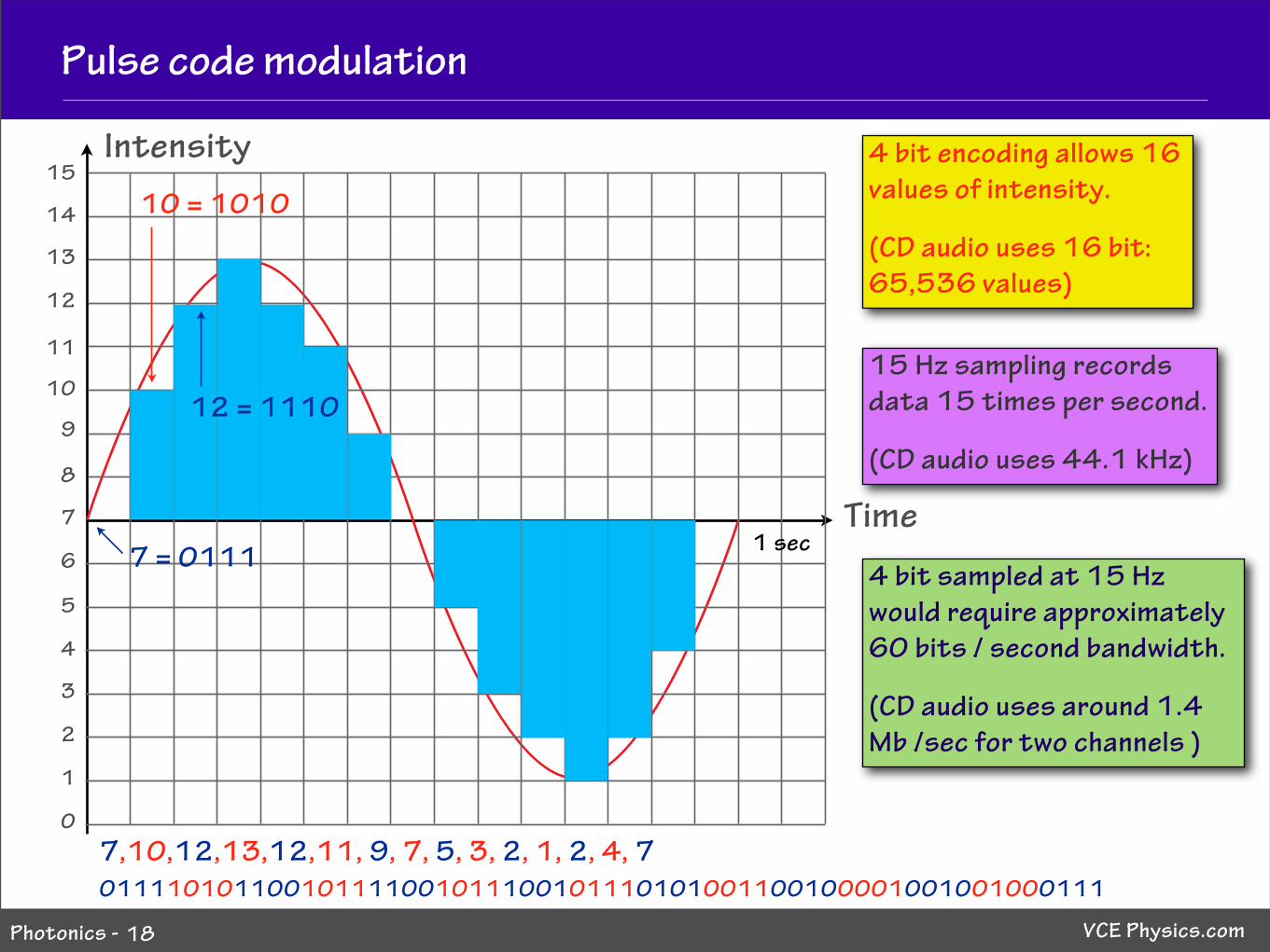
4 bit encoding allows 16 values of intensity.
(CD audio uses 16 bit: 65,536 values)
15 Hz sampling records data 15 times per second.
(CD audio uses 44.1 kHz)
7,10,12,13,12,11, 9, 7, 5, 3, 2, 1, 2, 4, 7
15
7 = 0111
10 = 1010
12 = 1110
011110101100101111001011100101110101001100100001001001000111
4 bit sampled at 15 Hz would require approximately 60 bits / second bandwidth.
(CD audio uses around 1.4 Mb /sec for two channels )
1 sec

VCE Physics.comPhotonics -
Light modulation
• Modulation is defined as the addition of information to a carrier signal, such as radio waves or electric current.
• Digital modulation refers to converting an analogue signal into a digital signal.
• Optical systems use changes in the intensity of light signals to convey data.
• Modulation occurs when digital electric signals are converted into light signals by a laser diode.
• Demodulation occurs when the light signal is converted into an electric signal by a photodiode.
19
Modulationdevice
Demodulationdevice
Light signal
Electrical signal
Electrical signal