photovoltaic powered water pumping systems: … · photovoltaic powered water pumping systems:...
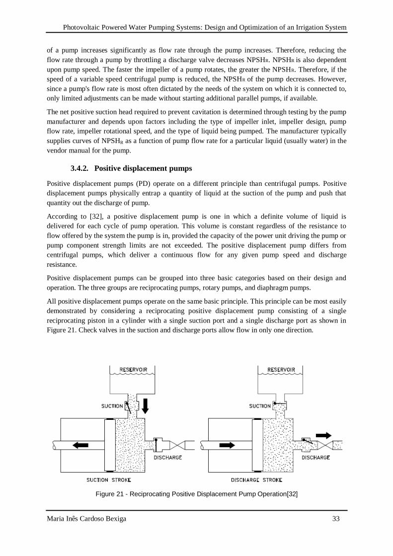
TRANSCRIPT
Photovoltaic Powered Water Pumping Systems: Design and Optimization of an Irrigation System
Maria Inês Cardoso Bexiga 1
UNIVERSIDADE DE LISBOA
FACULDADE DE CIÊNCIAS
DEPARTAMENTO DE ENGENHARIA GEOGRÁFICA, GEOFÍSICA E ENERGIA
Photovoltaic Powered Water Pumping Systems:
Design and optimization of an irrigation system
Maria Inês Cardoso Bexiga
Dissertação de Mestrado
Mestrado Integrado em Engenharia da Energia e do Ambiente
2014
Photovoltaic Powered Water Pumping Systems: Design and Optimization of an Irrigation System
Maria Inês Cardoso Bexiga 2
UNIVERSIDADE DE LISBOA
FACULDADE DE CIÊNCIAS
DEPARTAMENTO DE ENGENHARIA GEOGRÁFICA, GEOFÍSICA E ENERGIA
Photovoltaic Powered Water Pumping Systems:
Design and optimization of an irrigation system
Maria Inês Cardoso Bexiga
Dissertação de Mestrado
Mestrado Integrado em Engenharia da Energia e do Ambiente
Trabalho realizado sob a supervisão de
José Carlos Amador (Martifer Solar)
João Serra (FCUL)
2014
Photovoltaic Powered Water Pumping Systems: Design and Optimization of an Irrigation System
Maria Inês Cardoso Bexiga 1
Abstract
This work aims at the application of photovoltaic solar energy water pumping systems.
A state-of-the art of these systems is presented, considering their advantages and disadvantages in
different applications. A methodology is described as a guide to size and optimize solar water
pumping systems.
For that sizing, a multi-step method is presented and applied to a specific case of a grass field. A case
study suggested by Martifer Solar to size an irrigation photovoltaic water pumping system is
described. This system is studied for the location of the headquarters of the company, in Oliveira de
Frades, Portugal. The total area to irrigate was 16 119 m2.
Both solar resource and water demand must be evaluated in this process. In this application the daily
water demand varies from 15m3 to 80m
3, depending on the month. Average data from the solar
resource was estimated from a solar database website. This analysis showed that water demand
changes seasonally in a similar way as available solar radiation.
A match between PV array and motor/pump assembly was made, through the study of manufacturer’s
data of the different components. Curves from maximum power point of the PV array and equilibrium
operation point were calculated. The main goal is to match as much as possible both curves, with no
use of any electronic controller. The modulation of the system was made using Matlab.
After analyzing several configurations, it was concluded that the system would have 16 PV panels,
(2S×8P) with a DC motor with Kv=0.017 V/rpm and Ra=0.70Ω and associated storage water tanks. It
is assured that water demand is fulfilled throughout the year.
Keywords: irrigation, water demand, PV water-pumping, DC motor
Photovoltaic Powered Water Pumping Systems: Design and Optimization of an Irrigation System
Maria Inês Cardoso Bexiga 2
Resumo
Este trabalho tem como âmbito o estudo da possibilidade do uso de energia solar fotovoltaica em
sistemas de bombeamento de água.
Foi feito um estado da arte sobre estes sistemas, onde foram apresentadas vantagens e desvantagens
para diferentes aplicações. De seguida, é apresentada uma metodologia de dimensionamento de forma
a otimizar um sistema solar de bombeamento de água.
Como caso de estudo, foi sugerido pela empresa Martifer Solar o dimensionamento de um sistema de
irrigação para um relvado situado na sede da empresa, em Oliveira de Frades, Portugal. A área total do
relvado é 16 119m2.
Por se tratar de um relvado, a quantidade diária de água necessária varia ao longo dos meses desde
15m3 até 80m
3. De seguida, foi estudado o recurso solar para o local. Foi logo concluído que a
variação da quantidade de água necessária varia de forma semelhante com a radiação solar disponível.
Através do estudo de parâmetros dos vários componentes, foi feita uma correspondência entre os
módulos fotovoltaicos e o motor/bomba. Foram calculadas curvas de potência máxima do conjunto de
módulos e curvas de pontos de equilíbrio. O principal objetivo é modelar, usando o Matlab, as duas de
forma a ficaram o mais próximas possível, sem o uso de qualquer controlador eletrónico.
Após o estudo de várias configurações ficou concluído que o sistema seria constituído por 16 módulos
fotovoltaicos(2S×8P), com um motor com os parâmetros Kv=0.017 V/rpm e Ra=0.70Ω e com tanques
de armazenamento de água. A quantidade de água necessária fica assegurada ao longo de todo o ano.
Palavras-chave: irrigação, procura de água, bombeamento solar fotovoltaico, motor DC
Photovoltaic Powered Water Pumping Systems: Design and Optimization of an Irrigation System
Maria Inês Cardoso Bexiga 3
Index
Abstract ..............................................................................................................................................1
Resumo ..............................................................................................................................................2
List of Figures ....................................................................................................................................5
List of Tables ......................................................................................................................................7
List of Symbols...................................................................................................................................8
Nomenclature .....................................................................................................................................9
1. Introduction .............................................................................................................................. 10
1.1. Global context ................................................................................................................... 10
1.2. Water supply ..................................................................................................................... 10
1.3. Motivation ......................................................................................................................... 10
1.4. Scope ................................................................................................................................ 12
1.5. Methodology ..................................................................................................................... 12
2. State of the Art .......................................................................................................................... 13
2.1. Applications of PV water pumping systems ....................................................................... 13
2.2. Performance of a solar photovoltaic water pumping system – literature review................... 14
2.3. Advantages and disadvantages of PV powered pumping .................................................... 16
2.4. Market of solar pumping systems ....................................................................................... 17
3. Pumping system basic operation and components ...................................................................... 20
3.1. Pumping system configurations ......................................................................................... 21
3.2. System layout .................................................................................................................... 23
3.2.1. Direct-coupled system................................................................................................ 23
3.2.2. Battery-coupled system .............................................................................................. 23
3.3. Pumping system calculation ............................................................................................... 24
3.3.1. Total Dynamic Head (TDH) ....................................................................................... 24
3.3.2. Estimation of the Energy Demand .............................................................................. 26
3.4. Types of Pumps and pump selection .................................................................................. 28
3.4.1. Centrifugal Pumps ..................................................................................................... 28
Photovoltaic Powered Water Pumping Systems: Design and Optimization of an Irrigation System
Maria Inês Cardoso Bexiga 4
3.4.2. Positive displacement pumps ..................................................................................... 33
3.4.3. How to select – Centrifugal Pumps vs Positive Displacement ..................................... 36
3.5. Types of motors ................................................................................................................. 38
3.6. Maintenance ...................................................................................................................... 38
3.7. Limitations of Solar Powered Water Pumping Systems ...................................................... 39
4. Design and optimization of a solar water pump system .............................................................. 40
4.1. Available Solar energy and PV location ............................................................................. 40
4.2. Water requirement ............................................................................................................. 41
4.3. Water source ..................................................................................................................... 41
4.4. Method for optimal PV pumping system ............................................................................ 41
5. Case Study ................................................................................................................................ 45
5.1. Area and Location ............................................................................................................. 45
5.2. Water Needs ...................................................................................................................... 45
5.3. Hydraulic Power ................................................................................................................ 47
5.4. Configuration of the system ............................................................................................... 49
6. Conclusions .............................................................................................................................. 56
6.1. Case of study conclusions/Discussion ................................................................................ 56
6.2. The future of PV water-pumping systems .......................................................................... 56
References ........................................................................................................................................ 58
Appendix A : Location Plan .............................................................................................................. 62
Appendix B : Average Water Depth for Portugal ............................................................................... 63
Appendix C : Matlab File .................................................................................................................. 64
Appendix D : Lorentz motor-pump ................................................................................................... 65
Appendix E : PV module Mprime ..................................................................................................... 66
Photovoltaic Powered Water Pumping Systems: Design and Optimization of an Irrigation System
Maria Inês Cardoso Bexiga 5
List of Figures
Figure 1 – Example of a Village Water Supply System[5] ................................................................. 13
Figure 2 – Example of an irrigation system[5] ................................................................................... 14
Figure 3 - Block diagram of PV-powered water pumping system (dashed line means optional
components) ..................................................................................................................................... 20
Figure 4 – Surface suction pump-set[5] ............................................................................................. 22
Figure 5 – Submersible pump and motor[5]....................................................................................... 22
Figure 6 – Floating motor and pump[5] ............................................................................................. 22
Figure 7 – Submersible Pump and surface motor[5] .......................................................................... 22
Figure 8 - direct-coupled system ....................................................................................................... 23
Figure 9 - Battery-coupled system ..................................................................................................... 24
Figure 10 – Negative Suction Head ................................................................................................... 24
Figure 11 - Positive Suction Head ..................................................................................................... 25
Figure 12 - Well water levels[7] ........................................................................................................ 25
Figure 13 - Hydraulic Energy for different volume requirements ....................................................... 27
Figure 14 - Centrifugal pump[31] ...................................................................................................... 28
Figure 15 - Centrifugal Pump Diffuser[31] ........................................................................................ 29
Figure 16 - Radial flow centrifugal pump[31] .................................................................................... 29
Figure 17 - Axial flow centrifugal pump[31] ..................................................................................... 30
Figure 18 - Mixed flow centrifugal pumps[31] .................................................................................. 30
Figure 19 - Multi-stage centrifugal pump[31] .................................................................................... 31
Figure 20 - Centrifugal pump characteristic curve (example)[31] ...................................................... 31
Figure 21 - Reciprocating Positive Displacement Pump Operation[31] .............................................. 33
Figure 22 - Simple Gear Rotary Pump[31] ........................................................................................ 34
Figure 23 - Diaphragm Pump[31] ...................................................................................................... 35
Figure 24 - Positive Displacement Curve Characteristic Curve – Example[31] .................................. 36
Figure 25 - Idealized, actual Centrifugal and Positive Displacement Curves [32] ............................... 36
Figure 26 - Different pumps for different situations[35] .................................................................... 37
Figure 27 - Long-term average solar irradiation (source: http://solargis.info/) .................................... 40
Figure 28 - The deviation between MPP and EOP curves of the system (reproduced only for
discussion purpose)[1] ...................................................................................................................... 44
Figure 29 - Irradiation and Daily Irrigation ........................................................................................ 46
Figure 30 - Dependence of flow rate in head losses ........................................................................... 47
Figure 31 - Irradiation and Hydraulic Energy .................................................................................... 48
Figure 32 - Variation of peak power throughout the year ................................................................... 48
Figure 33 - IV curve for different radiations (from 100W/m2 to 1000W/m
2 with a 100W/m
2 step) ..... 49

Photovoltaic Powered Water Pumping Systems: Design and Optimization of an Irrigation System
Maria Inês Cardoso Bexiga 6
Figure 34 - Operation characteristics of the system for three different cases (7P×2S) (from 100W/m2 to
1000W/m2 with a 100W/m
2 step) ...................................................................................................... 50
Figure 35 - Operation characteristics of the system for three different cases (8P×2S) (from 100W/m2 to
1000W/m2 with a 100W/m
2 step) ...................................................................................................... 51
Figure 36 – Operation characteristics for case 2 and 4 for 7P×2S PV configuration (from 100W/m2 to
1000W/m2 with a 100W/m
2 step) ...................................................................................................... 52
Figure 37 -Operation characteristics for case 2 and 4 for 8P×2S PV configuration (from 100W/m2 to
1000W/m2 with a 100W/m
2 step) ...................................................................................................... 53
Figure 38 - Tank for water storage - T10500 model (http://www.affordablewatertanks.com) ............. 54

Photovoltaic Powered Water Pumping Systems: Design and Optimization of an Irrigation System
Maria Inês Cardoso Bexiga 7
List of Tables
Table 1 - Summary of principal advantages and disadvantages for diesel, wind and solar-powered
pumps [6] ......................................................................................................................................... 12
Table 2 - Summary of reported results on SPWPSs ........................................................................... 16
Table 3 - Irradiation in Oliveria de Frades [kWh/m2/day] .................................................................. 45
Table 4 - Water needs for grass [46] .................................................................................................. 46
Table 5 - Different combinations of Kv and Ra................................................................................... 50
Table 6 - Number of days of water assurance .................................................................................... 54
Table 7 - System's final configuration ............................................................................................... 55
Photovoltaic Powered Water Pumping Systems: Design and Optimization of an Irrigation System
Maria Inês Cardoso Bexiga 8
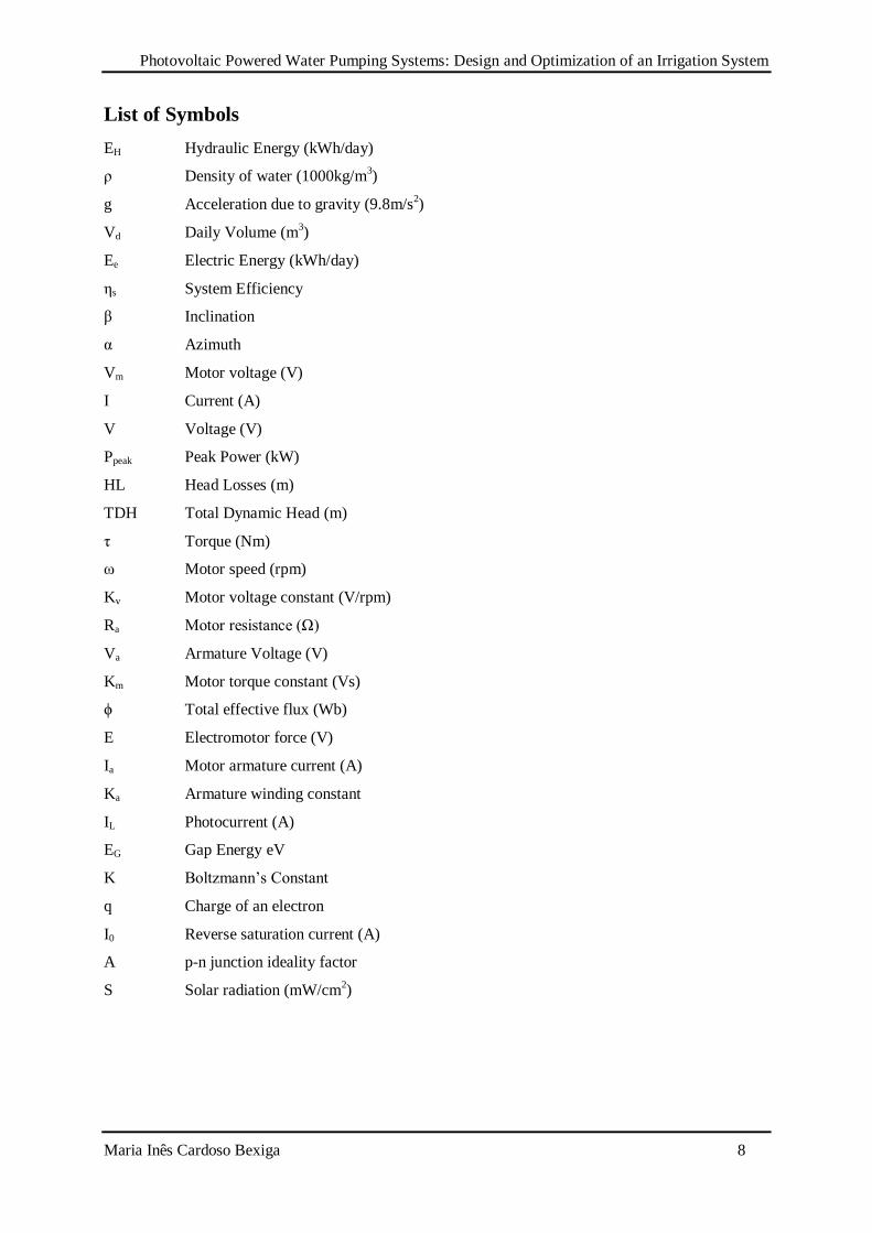
List of Symbols
EH Hydraulic Energy (kWh/day)
ρ Density of water (1000kg/m3)
g Acceleration due to gravity (9.8m/s2)
Vd Daily Volume (m3)
Ee Electric Energy (kWh/day)
ηs System Efficiency
β Inclination
α Azimuth
Vm Motor voltage (V)
I Current (A)
V Voltage (V)
Ppeak Peak Power (kW)
HL Head Losses (m)
TDH Total Dynamic Head (m)
τ Torque (Nm)
ω Motor speed (rpm)
Kv Motor voltage constant (V/rpm)
Ra Motor resistance (Ω)
Va Armature Voltage (V)
Km Motor torque constant (Vs)
ϕ Total effective flux (Wb)
E Electromotor force (V)
Ia Motor armature current (A)
Ka Armature winding constant
IL Photocurrent (A)
EG Gap Energy eV
K Boltzmann’s Constant
q Charge of an electron
I0 Reverse saturation current (A)
A p-n junction ideality factor
S Solar radiation (mW/cm2)
Photovoltaic Powered Water Pumping Systems: Design and Optimization of an Irrigation System
Maria Inês Cardoso Bexiga 9
Nomenclature
MPPT Maximum Power Point Tracker
PD Positive Displacement
NPSHR Required Net Positive Suction Head
NPSHA Available Net Positive Suction Head
BDCM Brushless DC motor
EOP Equilibrium Operation Point
MPP Maximum Power Point
P Parallel
S Series
Photovoltaic Powered Water Pumping Systems: Design and Optimization of an Irrigation System
Maria Inês Cardoso Bexiga 10
1. Introduction
1.1. Global context
Electricity is one of most versatile forms of energy and the one that better adapts to the actual world
needs. Modern society way of life would have not been possible without electrical energy and its use
in a large scale. There are innumerous machines that work with electrical energy. However, a big
amount of diesel and other fossil fuels based generators are still working around the world, and it still
is a solution for a lot of applications. Its use results in a dependence on fossil fuels leading to several
environmental problems, not only in its operation but also on the refinery and transport of these fuels.
In many cases, the use of fossil fuels based generator appears in remote areas, where electric grid
connection is difficult, expensive and sometimes impossible. In addition, the price of fossil fuels is
very unstable and the increasing trend is evident for the last decade [1].
Therefore, renewable energies such as solar, wind, hydropower, biomass and geothermal are potential
sources to supply global energy demand in a sustainable way, introducing an alternative that can
overcome the problems of costs of energy, energy supply and pollution [2]. Renewable energies can
lead to an increase of the energy supply security.
1.2. Water supply
Water is essential to life. Water consumption is not only made in a direct way but is also needed for
food production, cleaning, sanitation and other domestic and industrial functions.
An important part of the world population lives in a rural environment where the lack of
infrastructures is stimulating an exodus to urban centers or more developed regions [1]. Maintenance
of rural populations is needed in order to attend to several necessities.
Lack of water or its bad quality can cause severe sanitation, nutritional and economic problems to
affected populations. As well as access to water is critical for the survival of human beings, the good
use of it is critical in equal measure. Due to the sustainability of the water resource, water extraction
may not be bigger than its natural replacement [1].
The first priority is the supply of drinkable water for the consumption on the population itself, for
domestic animals and, when necessary, for agriculture. Unfortunately, it is usual in several regions of
the planet that people need to walk several kilometers to find water, and in the majority of these cases,
water quality is poor.
1.3. Motivation
There is energy consumption in every step of supply, treatment and water use. The intensity of energy
consumptions depends on which technology is used for each process. Infrastructures that supply water
for agriculture, domestic consumption or sanitation use treatment and distribution systems that require
significant amounts of energy.
Generally, the water supply problem is related to the local energy deficit to execute the extraction and
transportation work from the source to the place of consumption. Therefore, the solution for this could
be the introduction of off-grid systems of energy production, since the electric grid extension can be
very expensive in comparison to other alternatives.
All over the world, electrical and diesel-powered water pumping systems are widely used for irrigation
or village supply applications. The problems mentioned above about the use of conventional energy
Photovoltaic Powered Water Pumping Systems: Design and Optimization of an Irrigation System
Maria Inês Cardoso Bexiga 11
sources have created an interest in choosing renewable energy sources to power water pumping
systems since these energy resources are available anywhere [3].
Water pumping systems are known for many years, where the systems were manual or based on
animal traction. Today, pumps using diesel motors became very popular, however, besides the fuel
prices, availability and environmental problems, they require frequent maintenance.
Pumps that work using wind energy have their use limited to wind conditions that are difficult to
predict. Usually the term “wind powered pumps” refers to wind mills that use the wind to
mechanically extract water from a well. The use of a wind turbine to produce electric energy to then
power the water pump is not yet very common. However, these systems are now starting to be used
and are being financed in some locations by state institutions [4]. Before applying wind turbines the
local wind data should be carefully measured and analysed. It is possible that the terrain morphology
may reduce more than expected the energy output. However, if the wind speed is actually higher than
expected most likely the output will increase significantly.
Solar pumps are recent (the first were installed in the 70’s [1]) and they are less known, but
photovoltaic (PV) pumping systems present one of the most interesting and potentially cost-effective
applications, used for both irrigation needs and drinkable water supply, including also the prospect of
desalination [5].
Solar water pumping is done all over the world and greatly enhances the quality of life of people's
living in rural and remote communities. A solar water pumping system does not have to use batteries
to provide the power as the pump will operate during the day by pumping water into a tank for use at
night.
The variety of water pumping applications is considerable and they can vary widely, both in their
requirements and the conditions under which water must be pumped. Volume of required water,
capacity of the source to deliver the water, depth from which the water is pumped, season and time of
the pumping, and most importantly, amount of solar radiation at the point where the water is to be
extracted are important factors when designing such pumping systems.
However, for the spread of a new technology, is not enough to have a reliable system. Design and
sizing process are very important, not just for good system reliability, but also for economical
sustainability.
Photovoltaic Powered Water Pumping Systems: Design and Optimization of an Irrigation System
Maria Inês Cardoso Bexiga 12
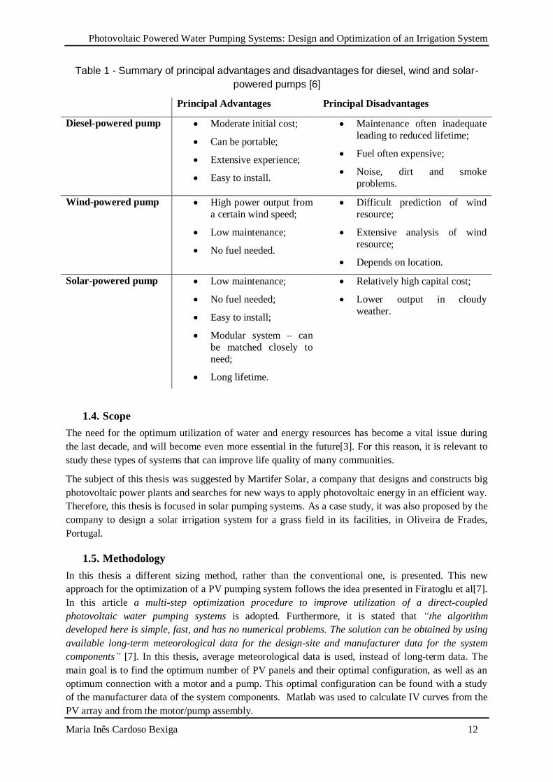
Table 1 - Summary of principal advantages and disadvantages for diesel, wind and solar-
powered pumps [6]
Principal Advantages Principal Disadvantages
Diesel-powered pump Moderate initial cost;
Can be portable;
Extensive experience;
Easy to install.
Maintenance often inadequate
leading to reduced lifetime;
Fuel often expensive;
Noise, dirt and smoke
problems.
Wind-powered pump High power output from
a certain wind speed;
Low maintenance;
No fuel needed.
Difficult prediction of wind
resource;
Extensive analysis of wind
resource;
Depends on location.
Solar-powered pump Low maintenance;
No fuel needed;
Easy to install;
Modular system – can
be matched closely to
need;
Long lifetime.
Relatively high capital cost;
Lower output in cloudy
weather.
1.4. Scope
The need for the optimum utilization of water and energy resources has become a vital issue during
the last decade, and will become even more essential in the future[3]. For this reason, it is relevant to
study these types of systems that can improve life quality of many communities.
The subject of this thesis was suggested by Martifer Solar, a company that designs and constructs big
photovoltaic power plants and searches for new ways to apply photovoltaic energy in an efficient way.
Therefore, this thesis is focused in solar pumping systems. As a case study, it was also proposed by the
company to design a solar irrigation system for a grass field in its facilities, in Oliveira de Frades,
Portugal.
1.5. Methodology
In this thesis a different sizing method, rather than the conventional one, is presented. This new
approach for the optimization of a PV pumping system follows the idea presented in Firatoglu et al[7].
In this article a multi-step optimization procedure to improve utilization of a direct-coupled
photovoltaic water pumping systems is adopted. Furthermore, it is stated that “the algorithm
developed here is simple, fast, and has no numerical problems. The solution can be obtained by using
available long-term meteorological data for the design-site and manufacturer data for the system
components” [7]. In this thesis, average meteorological data is used, instead of long-term data. The
main goal is to find the optimum number of PV panels and their optimal configuration, as well as an
optimum connection with a motor and a pump. This optimal configuration can be found with a study
of the manufacturer data of the system components. Matlab was used to calculate IV curves from the
PV array and from the motor/pump assembly.

Photovoltaic Powered Water Pumping Systems: Design and Optimization of an Irrigation System
Maria Inês Cardoso Bexiga 13
2. State of the Art
2.1. Applications of PV water pumping systems
Nowadays, PV pumps are mainly used in stand-alone systems in rural and isolated areas and used
principally for three types of applications:
village water supply
irrigation
livestock watering
A solar pump for village water supply is shown schematically in Figure 1.With village water supply, a
constant water demand occurs throughout the year, meaning that there is need to store water for
periods of low solar radiation. This can be done using a water tank. Instead of storage tanks, battery
banks can also be a solution. Even so, storage tanks have the advantage of taking some stress off the
pump (it will work continuously with some long stops instead of working every time the demand
requires), being a more economical and simpler system [4]. For a village water supply a storage
capability for a few days of demand (this depends on the weather of the location) is usually required.
The system has to be as efficient as possible, and water losses should also be reduced as much as
possible [8].
Figure 1 – Example of a Village Water Supply System[4]
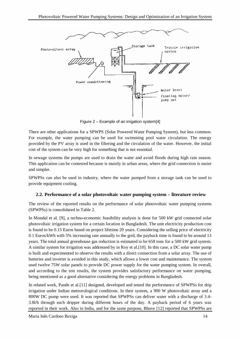
A solar irrigation system (Figure 2) needs to take into account the fact that demand for irrigation water
will vary throughout the year. Peak demand during the irrigation seasons is often more than twice the
average demand. This means that solar pumps for irrigation are underutilized for most of the year.
Attention should be paid to the system of water distribution and application to the crops. The tank has
to be high enough to provide the needed pressure for irrigation. The system should minimize water
losses, without imposing significant additional vertical pumping distance on the pumping system [8].
For the livestock water needs, the storage tank doesn’t have to be very high because pressure
requirements are not so demanding. Most of the times, for example, animals can drink directly from
the water storage tank.
Photovoltaic Powered Water Pumping Systems: Design and Optimization of an Irrigation System
Maria Inês Cardoso Bexiga 14
Figure 2 – Example of an irrigation system[4]
There are other applications for a SPWPS (Solar Powered Water Pumping System), but less common.
For example, the water pumping can be used for swimming pool water circulation. The energy
provided by the PV array is used in the filtering and the circulation of the water. However, the initial
cost of the system can be very high for something that is not essential.
In sewage systems the pumps are used to drain the water and avoid floods during high rain season.
This application can be contested because is mainly in urban areas, where the grid connection is easier
and simpler.
SPWPSs can also be used in industry, where the water pumped from a storage tank can be used to
provide equipment cooling.
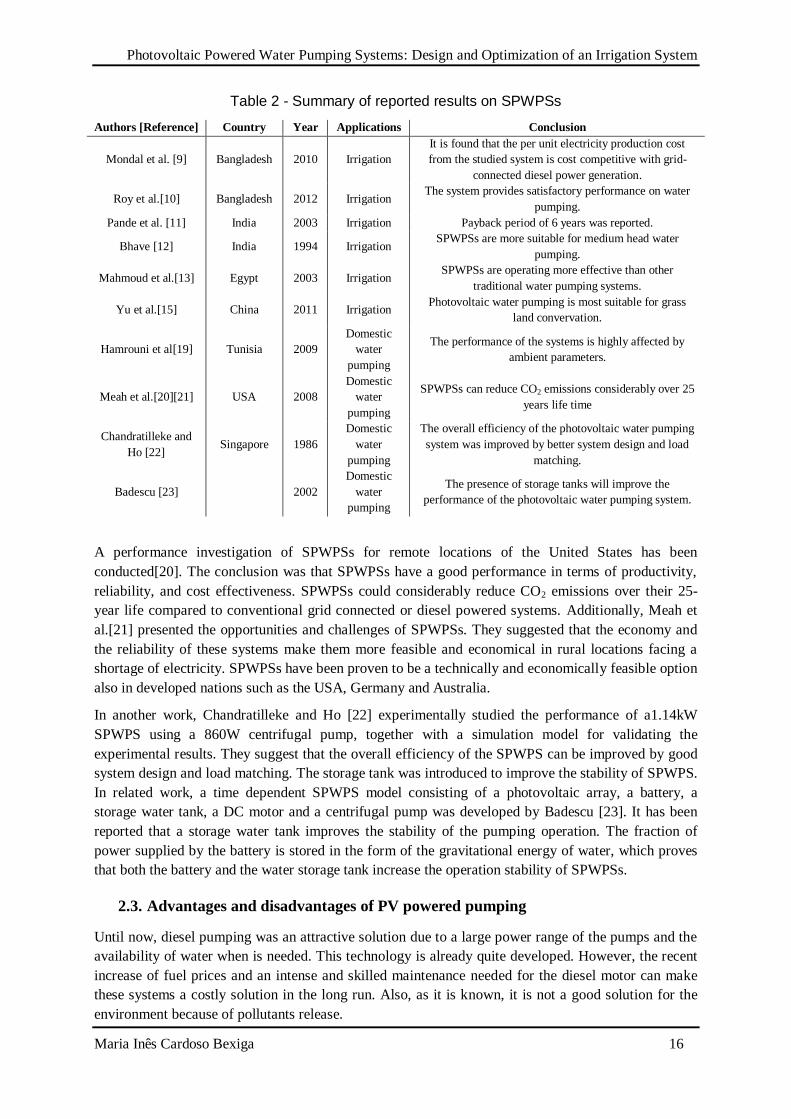
2.2. Performance of a solar photovoltaic water pumping system – literature review
The review of the reported results on the performance of solar photovoltaic water pumping systems
(SPWPSs) is consolidated in Table 2.
In Mondal et al. [9], a techno-economic feasibility analysis is done for 500 kW grid connected solar
photovoltaic irrigation system for a certain location in Bangladesh. The unit electricity production cost
is found to be 0.15 Euros based on project lifetime 20 years. Considering the selling price of electricity
0.1 Euros/kWh with 5% increasing rate annually to the grid, the payback time is found to be around 13
years. The total annual greenhouse gas reduction is estimated to be 658 tons for a 500 kW grid system.
A similar system for irrigation was addressed by in Roy et al.[10]. In this case, a DC solar water pump
is built and experimented to observe the results with a direct connection from a solar array. The use of
batteries and inverter is avoided in this study, which allows a lower cost and maintenance. The system
used twelve 75W solar panels to provide DC power supply for the water pumping system. In overall,
and according to the test results, the system provides satisfactory performance on water pumping,
being mentioned as a good alternative considering the energy problems in Bangladesh.
In related work, Pande et al.[11] designed, developed and tested the performance of SPWPSs for drip
irrigation under Indian meteorological conditions. In their system, a 900 W photovoltaic array and a
800W DC pump were used. It was reported that SPWPSs can deliver water with a discharge of 3.4-
3.8l/h through each dripper during different hours of the day. A payback period of 6 years was
reported in their work. Also in India, and for the same purpose, Bhave [12] reported that SPWPSs are
Photovoltaic Powered Water Pumping Systems: Design and Optimization of an Irrigation System
Maria Inês Cardoso Bexiga 15
more suitable for low and medium depth water pumping in areas where grid connection is not
available. Moreover, it was concluded that SPWPSs are economical in operation only during peak
sunshine hours. However, this study was made in 1994, and since that time, solar technology evolved
significantly.
In a similar investigation, in Egypt, Mahmoud et al.[13] investigated the performance of SPWPSs
using batteries for sprinkling and dripping irrigation systems. It has been concluded that SPWPSs can
be used efficiently for water pumping in agriculture sectors. The cost of the water pumped by
photovoltaic systems is much less than the cost of water pumped using conventional grid connection
and diesel generators. They also concluded that SPWPSs also improve the quality of life and promote
socio-economic development in rural areas. In a similar attempt, Qoaider and Steinbrecht [14]
investigated the technical feasibility of SPWPSs in a region of Southern Egypt. In their work, the
technical design and the life cost of the SPWPSs were calculated. The pumping system was designed
to pump 110,000 m3 of daily water to irrigate 1260 ha and also to power the adjacent households.
Their studies concluded that SPWPSs are an economically competitive option to supply energy to off-
grid communities in arid regions compared to diesel generation systems. The same conclusion is
reported by Yu et al.[15] in North West China. The performance of a solar powered irrigation system
was assessed for sustaining pasture lands in arid lands. These types of systems are cost effective,
which contributing to grassland conservation.
In another work, Mokeddem et al.[16] studied the performance of a direct coupled SPWPS under the
meteorological conditions of Algeria over a period of four months. The system performance was
monitored under different conditions with two static head configurations. Their system is composed of
a 1.5 kWp photovoltaic array, a DC motor and a centrifugal pump. It has been reported that directly
coupled SPWPSs to the PV array are suitable for low head irrigation in remote areas, which are not
connected to the national grid and where access to water comes as a first priority issue. Their system
runs with low maintenance due to the absence of battery and electronic control. Similar investigations
on the electrical and hydraulic performance of a small-scale photovoltaic irrigation system were
performed in the Algerian Sahara region [17]. Approximately sixty SPWPSs were installed in the
remote regions to supply water for domestic use and irrigation of four different crops, namely wheat,
potatoes, tomatoes and sunflowers. It has been reported that SPWPSs are suitable for small-scale
irrigation in Sahara regions. The systems could easily cover the daily water need rates for small-scale
irrigation with an area of less than 2ha. Similarly, Boutelhig et al. [18] studied the performance of
SPWPSs with four different configurations (2 parallel (P) × 2 series (S), 2P × 1S, 1P × 2S, and 1
module) at different heads between 10 m and 40 m under the meteorological conditions of the
Algerian desert area. It was reported that the combination of two photovoltaic array configurations (2P
× 1S) and (1P × 2S) is suitable to provide the optimum energy to drive the pumps. The selected
photovoltaic configurations pumped the maximum volume of water in the tested period.
For domestic water pumping, Hamrouni et al[19] assessed the performance of SPWPSs both
theoretically and experimentally. The system consists of a photovoltaic generator, a DC-DC converter,
a DC-AC inverter, s submersed type motor-pump and a storage tank. It has been reported that the
values of solar radiation will affect the global efficiency of the pump. The maximum performance of
the pump was reached during the middle of the day. However, the performance of the system was
degraded due to meteorological parameters such as the solar intensity, the ambient temperature, the
wind velocity and the relative humidity. They also confirmed that the theoretical simulation results are
close to the experimentally predicted results with acceptable errors.
Photovoltaic Powered Water Pumping Systems: Design and Optimization of an Irrigation System
Maria Inês Cardoso Bexiga 16
Table 2 - Summary of reported results on SPWPSs
Authors [Reference] Country Year Applications Conclusion
Mondal et al. [9] Bangladesh 2010 Irrigation
It is found that the per unit electricity production cost
from the studied system is cost competitive with grid-
connected diesel power generation.
Roy et al.[10] Bangladesh 2012 Irrigation The system provides satisfactory performance on water
pumping.
Pande et al. [11] India 2003 Irrigation Payback period of 6 years was reported.
Bhave [12] India 1994 Irrigation SPWPSs are more suitable for medium head water
pumping.
Mahmoud et al.[13] Egypt 2003 Irrigation SPWPSs are operating more effective than other
traditional water pumping systems.
Yu et al.[15] China 2011 Irrigation Photovoltaic water pumping is most suitable for grass
land convervation.
Hamrouni et al[19] Tunisia 2009
Domestic
water
pumping
The performance of the systems is highly affected by
ambient parameters.
Meah et al.[20][21] USA 2008
Domestic
water
pumping
SPWPSs can reduce CO2 emissions considerably over 25
years life time
Chandratilleke and
Ho [22] Singapore 1986
Domestic
water
pumping
The overall efficiency of the photovoltaic water pumping
system was improved by better system design and load
matching.
Badescu [23] 2002
Domestic
water
pumping
The presence of storage tanks will improve the
performance of the photovoltaic water pumping system.
A performance investigation of SPWPSs for remote locations of the United States has been
conducted[20]. The conclusion was that SPWPSs have a good performance in terms of productivity,
reliability, and cost effectiveness. SPWPSs could considerably reduce CO2 emissions over their 25-
year life compared to conventional grid connected or diesel powered systems. Additionally, Meah et
al.[21] presented the opportunities and challenges of SPWPSs. They suggested that the economy and
the reliability of these systems make them more feasible and economical in rural locations facing a
shortage of electricity. SPWPSs have been proven to be a technically and economically feasible option
also in developed nations such as the USA, Germany and Australia.
In another work, Chandratilleke and Ho [22] experimentally studied the performance of a1.14kW
SPWPS using a 860W centrifugal pump, together with a simulation model for validating the
experimental results. They suggest that the overall efficiency of the SPWPS can be improved by good
system design and load matching. The storage tank was introduced to improve the stability of SPWPS.
In related work, a time dependent SPWPS model consisting of a photovoltaic array, a battery, a
storage water tank, a DC motor and a centrifugal pump was developed by Badescu [23]. It has been
reported that a storage water tank improves the stability of the pumping operation. The fraction of
power supplied by the battery is stored in the form of the gravitational energy of water, which proves
that both the battery and the water storage tank increase the operation stability of SPWPSs.
2.3. Advantages and disadvantages of PV powered pumping
Until now, diesel pumping was an attractive solution due to a large power range of the pumps and the
availability of water when is needed. This technology is already quite developed. However, the recent
increase of fuel prices and an intense and skilled maintenance needed for the diesel motor can make
these systems a costly solution in the long run. Also, as it is known, it is not a good solution for the
environment because of pollutants release.
Photovoltaic Powered Water Pumping Systems: Design and Optimization of an Irrigation System
Maria Inês Cardoso Bexiga 17
Photovoltaic systems are used to pump water for livestock, plants or humans. Since the need for water
is bigger on hot sunny days, the technology is a suitable choice for this application.
One of the strong points of solar powered pumps is its reliability. It usually requires little maintenance
(3 to 5 years is the gap period between checkups). Pumps designed for these systems have a high
efficiency allowing the reduction of solar array power, making the initial cost lower[4].
PV pumping has the best cost effectiveness in small distributed stand alone situations outside the
electric grid [4]. These are the factors that made solar powered pumps emerge in the market.
Although water pumps are getting more efficient, water demand is also increasing rapidly. For this
reason, pumps are turning into a high energy consumption equipment. PV systems have come down in
price in the last 30 years, and are now available in almost every country in the world. The PV
technology is also very reliable if well designed and installed and a local infrastructure is created for
long term maintenance. The weak point today is often the battery and battery component, especially if
the wrong battery technology is chosen.
PV powered pumping systems are excellent for small (when combustion engines are less economical)
to medium scale pumping. The main disadvantage of these systems is the high initial investment. The
most effective way to minimize the cost of solar pumping is to decrease the water demand through
flow control. Drip irrigation, lower water consuming toilets, for example, can considerably reduce the
pumped water.
2.4. Market of solar pumping systems
The market associated with green energy has increased since the concern with pollution and climate
change issues became important worldwide.
Pashupathy Gopalan, President of SunEdison (a global company of renewable energy solutions) for
the Asia Pacific and Middle East regions, believes that solar power is the future for irrigated
agriculture, and the market could be huge.
Irrigation is a big business. Global information from 2009 (the most recent available data from the
U.N.’s Food and Agriculture Organization) indicates that the countries with the largest irrigated
areas were India (39 million hectares), China (19 million), and the United States (17 million).
SunEdison’s Gopalan comments that India has nearly half a billion people connected to agriculture for
their livelihoods. It has between 26 and 27 million irrigation pumps, of which seven to eight million
run on liquid fuel. This fuel is typically diesel, but as many as a million pumps run on subsidized
kerosene – originally meant for lighting usage. According to Gopalan, the diesel costs may represent
30 to 50% of the total value of the grains produced. Despite the high costs, liquid fuels are used
because half a billion Indians don’t have sufficient access to electricity.
The remaining 19 or 20 million pumps run on electricity, but that is also not without its problems.
Since 1947, the Indian government has heavily subsidized electricity destined for irrigation. It’s either
provided at no cost, or the equivalent of one or two cents-per-kilowatt hour. These subsidies create
enormous government financial losses. The other problem is that, because the utilities make no
money, they have no incentive to approve applications for electrical irrigation pumping.
For these reasons, solar water pumps can dramatically increase productivity and reduce dependence on
diesel, which is an immense foreign exchange drain.
To date, SunEdison has spent the past two and a half years testing this value proposition. In the first
eighteen months, they developed and tested the product and applied solutions. Over the following
Photovoltaic Powered Water Pumping Systems: Design and Optimization of an Irrigation System
Maria Inês Cardoso Bexiga 18
year, they installed solar pumping installations in about 500 locations. Some of these initial
installations have been sold directly (without government support) to farmers who are using diesel and
state governments have also expressed an interest in the solar irrigation, since it cuts down on the
amount of electricity given away while improving the yields of local farmers.
Government subsidies are still critical in this area because farmers used to free or low-cost power face
high investment costs, and don’t see the savings. However, the governments will cut the benefits in the
long run, so they are motivated to make this work.
Gopalan comments that solar pumps are well suited to the irrigation task. Cloudy or rainy days may
reduce solar output, but they also minimize the need for water: In my view solar irrigation is almost
the perfect example of solar – you get the water when the crops need it when and when the farmer
needs to work the field (rather than at night which is more dangerous and unproductive). Add a
variable frequency drive to the equation and you can pump earlier into the day and later into the
afternoon.
India represents about 40% of the world irrigation pump market so global capacity is about two to
two-and-a-half times that. This would be a huge step forward in improving both the economic and
environmental aspects related to the pumping of water. Still to be resolved are supply issues relating to
the water itself. Globally, 20% of the aquifers are reported to be unable to recharge quickly enough to
offset withdrawals. Large parts of India, China, and the U.S. fall within the problem areas.
In fact, according to the Global Water Forum, groundwater in India accounts for 65% of total
irrigation water, and estimates suggest that 60% of India’s groundwater sources will be in a critical
state of degradation in the next two decades. It is therefore imperative that in the foreseeable future,
the solar water solution be combined with intelligent water applications. Otherwise, there is the risk
that the better solar pumping solutions result in the perverse outcome of excessive water withdrawal.
A good place to start would be to apply integrated systems thinking to irrigation: start with the most
efficient application to the desired crops, and design the system accordingly.
In agriculture, this implies a more effective and targeted utilization of the pumped water, often in the
form of drip irrigation, where water is applied slowly and directly to the areas where it is most
needed. Such practices can reduce water use by up to 70% and minimize the required pumping
capabilities. Higher efficiency systems lead to increased crop yields with less water and reduces the
power needed for pumping.
Several of SunEdison’s customers utilize drip irrigation systems today, but that number must be vastly
increased. In fact, water demand in India is estimated to double by 2030 if more efficient practices are
not applied. Globally, agriculture accounts for 67% of the world’s total water withdrawal and 86% of
consumption. In Asia and Africa, 85-90% of all freshwater is used for irrigation. By 2025, agricultural
consumption is expected to increase by 20%. At the same time domestic and industrial sectors are
increasing their consumption of water, further exacerbating the issue.
Clearly, solar irrigation is urgently needed. It replaces costly, fuel-intensive, and wasteful practices of
today. However, in the long run it must be integrated into an intelligent systems-thinking approach
that reduces both the use of fossil fuel and water itself. The advantages offered by drip irrigation
make it an ideal solution for the second half of the equation. Combining solar pumping and drip
irrigation offers a far better solution with reduced carbon footprint, elimination of conventional fuel
use, improved yields, and water conservation. Given the increased demand we will see on both water
and energy in the coming decades, these practices will need to move from being novelties to the status
quo. There doesn’t appear to be much of an alternative. (adapted from: Forbes Magazine – 4/04/2014)

Photovoltaic Powered Water Pumping Systems: Design and Optimization of an Irrigation System
Maria Inês Cardoso Bexiga 19
The market of solar irrigation is therefore a huge one. What was made in India can also be made in
order countries of Africa and Asia, countries with regions where it is difficult to connect to the electric
grid.
Many companies have invested in this new rising market, making prices decrease due to
competitiveness between them. From the large number of companies that offer different systems of
water solar pumps, Lorentz and Grundfos are two of the biggest ones. Both have several types of
pumps for different applications, not only for agriculture but also for industrial and domestic
applications. Lorentz designs, develops and manufactures a wide range of systems using solar pumps.
The company also manufactures its own solar panels, offering to the customer the complete pumping
system. There are Lorentz’s projects in different countries like USA and Pakistan. Grundfos is also an
international manufacturer of water pumps. However most of their products for irrigation consist in
AC motor-pumps to be coupled with solar panels and inverter. They also don’t have specific solutions
for SPWPSs.
Photovoltaic Powered Water Pumping Systems: Design and Optimization of an Irrigation System
Maria Inês Cardoso Bexiga 20
3. Pumping system basic operation and components
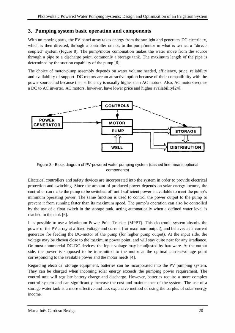
With no moving parts, the PV panel array takes energy from the sunlight and generates DC electricity,
which is then directed, through a controller or not, to the pump/motor in what is termed a “direct-
coupled” system (Figure 8). The pump/motor combination makes the water move from the source
through a pipe to a discharge point, commonly a storage tank. The maximum length of the pipe is
determined by the suction capability of the pump [6].
The choice of motor-pump assembly depends on water volume needed, efficiency, price, reliability
and availability of support. DC motors are an attractive option because of their compatibility with the
power source and because their efficiency is usually higher than AC motors. Also, AC motors require
a DC to AC inverter. AC motors, however, have lower price and higher availability[24].
Figure 3 - Block diagram of PV-powered water pumping system (dashed line means optional
components)
Electrical controllers and safety devices are incorporated into the system in order to provide electrical
protection and switching. Since the amount of produced power depends on solar energy income, the
controller can make the pump to be switched off until sufficient power is available to meet the pump’s
minimum operating power. The same function is used to control the power output to the pump to
prevent it from running faster than its maximum speed. The pump’s operation can also be controlled
by the use of a float switch in the storage tank, acting automatically when a defined water level is
reached in the tank [6].
It is possible to use a Maximum Power Point Tracker (MPPT). This electronic system absorbs the
power of the PV array at a fixed voltage and current (for maximum output), and behaves as a current
generator for feeding the DC-motor of the pump (for higher pump output). At the input side, the
voltage may be chosen close to the maximum power point, and will stay quite near for any irradiance.
On most commercial DC-DC devices, the input voltage may be adjusted by hardware. At the output
side, the power is supposed to be transmitted to the motor at the optimal current/voltage point
corresponding to the available power and the motor needs [4].
Regarding electrical storage equipment, batteries can be incorporated into the PV pumping system.
They can be charged when incoming solar energy exceeds the pumping power requirement. The
control unit will regulate battery charge and discharge. However, batteries require a more complex
control system and can significantly increase the cost and maintenance of the system. The use of a
storage water tank is a more effective and less expensive method of using the surplus of solar energy
income.
Photovoltaic Powered Water Pumping Systems: Design and Optimization of an Irrigation System
Maria Inês Cardoso Bexiga 21
The main disadvantage of the use of batteries or MPPT is the requirement of at least one additional
electronic component to the systems; hence, they become more expensive, more complicated, and less
reliable [7].
To ensure compatibility, it is important that the components are designed as part of an integrated
system [6].
In general, the main factors that affect the selection of a solar powered pump/motor are:
Vertical distance from water source to application (meters);
The water source (surface vs. well);
The available electric power (peak power) and total energy produced by the PV panel array;
The water requirement (in daily cubic meters) [25].
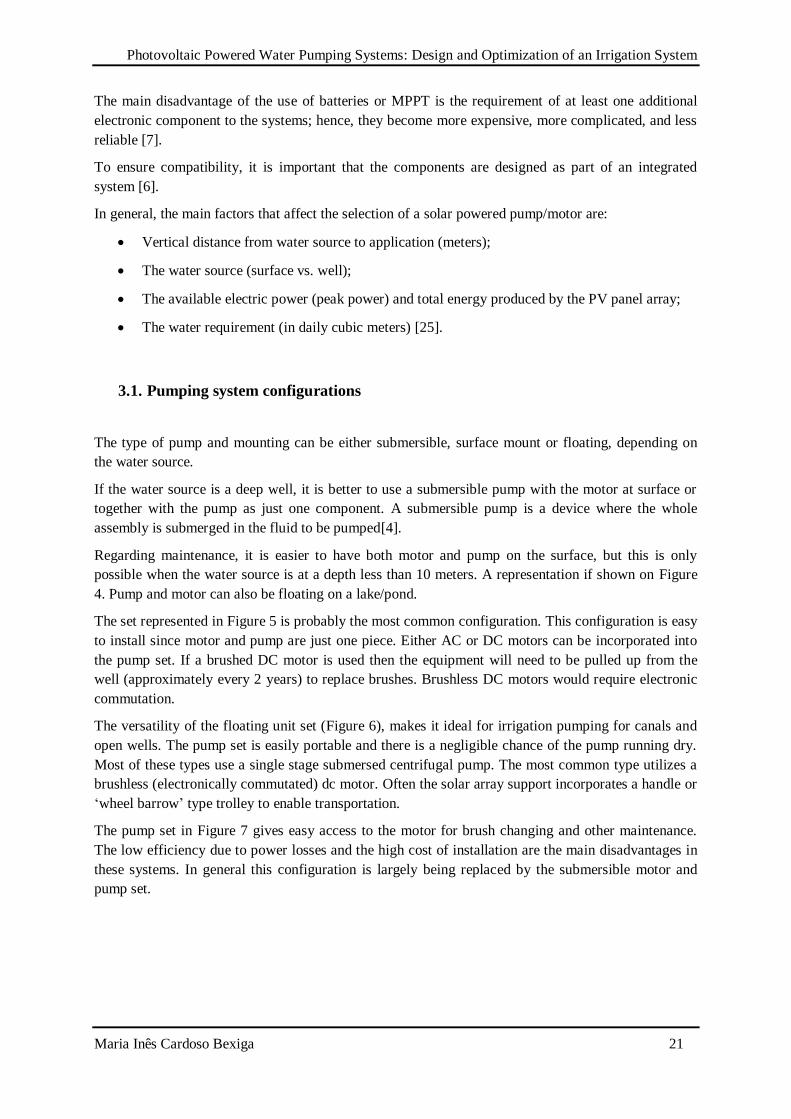
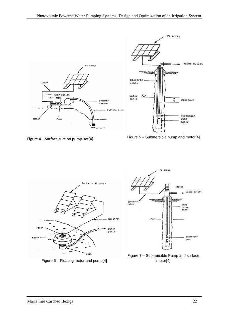
3.1. Pumping system configurations
The type of pump and mounting can be either submersible, surface mount or floating, depending on
the water source.
If the water source is a deep well, it is better to use a submersible pump with the motor at surface or
together with the pump as just one component. A submersible pump is a device where the whole
assembly is submerged in the fluid to be pumped[4].
Regarding maintenance, it is easier to have both motor and pump on the surface, but this is only
possible when the water source is at a depth less than 10 meters. A representation if shown on Figure
4. Pump and motor can also be floating on a lake/pond.
The set represented in Figure 5 is probably the most common configuration. This configuration is easy
to install since motor and pump are just one piece. Either AC or DC motors can be incorporated into
the pump set. If a brushed DC motor is used then the equipment will need to be pulled up from the
well (approximately every 2 years) to replace brushes. Brushless DC motors would require electronic
commutation.
The versatility of the floating unit set (Figure 6), makes it ideal for irrigation pumping for canals and
open wells. The pump set is easily portable and there is a negligible chance of the pump running dry.
Most of these types use a single stage submersed centrifugal pump. The most common type utilizes a
brushless (electronically commutated) dc motor. Often the solar array support incorporates a handle or
‘wheel barrow’ type trolley to enable transportation.
The pump set in Figure 7 gives easy access to the motor for brush changing and other maintenance.
The low efficiency due to power losses and the high cost of installation are the main disadvantages in
these systems. In general this configuration is largely being replaced by the submersible motor and
pump set.
Photovoltaic Powered Water Pumping Systems: Design and Optimization of an Irrigation System
Maria Inês Cardoso Bexiga 22
Figure 4 – Surface suction pump-set[4]
Figure 5 – Submersible pump and motor[4]
Figure 6 – Floating motor and pump[4]
Figure 7 – Submersible Pump and surface
motor[4]
Photovoltaic Powered Water Pumping Systems: Design and Optimization of an Irrigation System
Maria Inês Cardoso Bexiga 23
3.2. System layout
There are two basic configurations of PV water pumping systems battery-coupled and direct-coupled.
For a particular case of study, several factors must be considered in the process of choosing the best
layout in order to optimize the system.
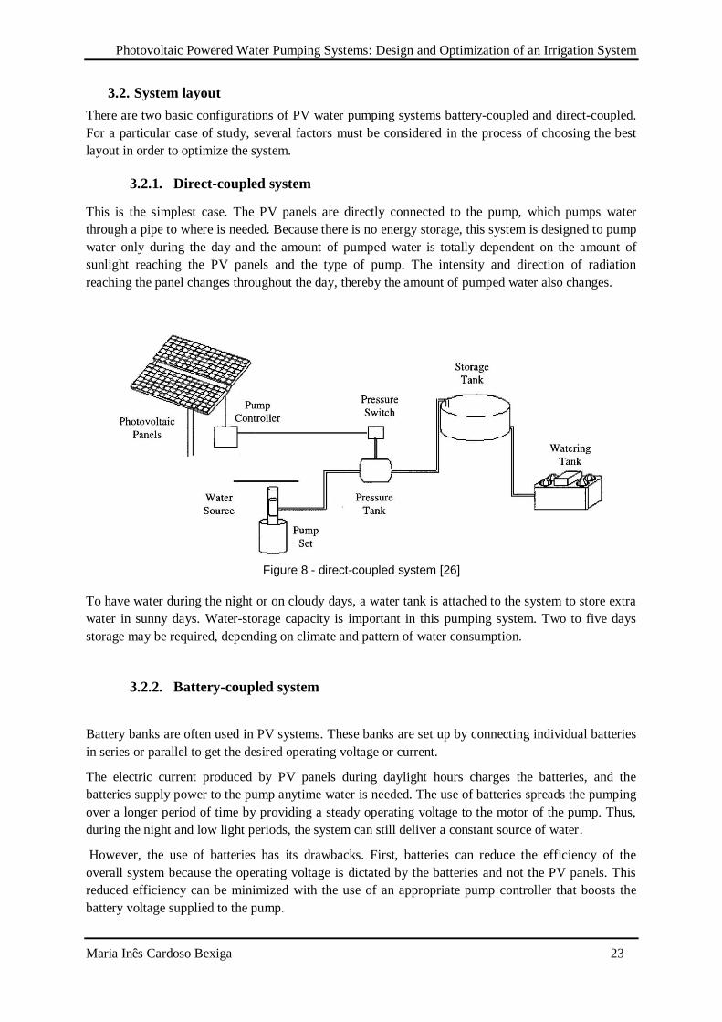
3.2.1. Direct-coupled system
This is the simplest case. The PV panels are directly connected to the pump, which pumps water
through a pipe to where is needed. Because there is no energy storage, this system is designed to pump
water only during the day and the amount of pumped water is totally dependent on the amount of
sunlight reaching the PV panels and the type of pump. The intensity and direction of radiation
reaching the panel changes throughout the day, thereby the amount of pumped water also changes.
Figure 8 - direct-coupled system [26]
To have water during the night or on cloudy days, a water tank is attached to the system to store extra
water in sunny days. Water-storage capacity is important in this pumping system. Two to five days
storage may be required, depending on climate and pattern of water consumption.
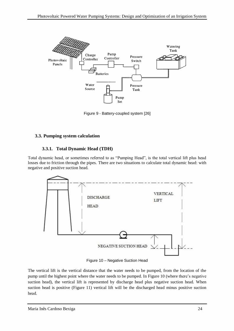
3.2.2. Battery-coupled system
Battery banks are often used in PV systems. These banks are set up by connecting individual batteries
in series or parallel to get the desired operating voltage or current.
The electric current produced by PV panels during daylight hours charges the batteries, and the
batteries supply power to the pump anytime water is needed. The use of batteries spreads the pumping
over a longer period of time by providing a steady operating voltage to the motor of the pump. Thus,
during the night and low light periods, the system can still deliver a constant source of water.
However, the use of batteries has its drawbacks. First, batteries can reduce the efficiency of the
overall system because the operating voltage is dictated by the batteries and not the PV panels. This
reduced efficiency can be minimized with the use of an appropriate pump controller that boosts the
battery voltage supplied to the pump.
Photovoltaic Powered Water Pumping Systems: Design and Optimization of an Irrigation System
Maria Inês Cardoso Bexiga 24
Figure 9 - Battery-coupled system [26]
3.3. Pumping system calculation
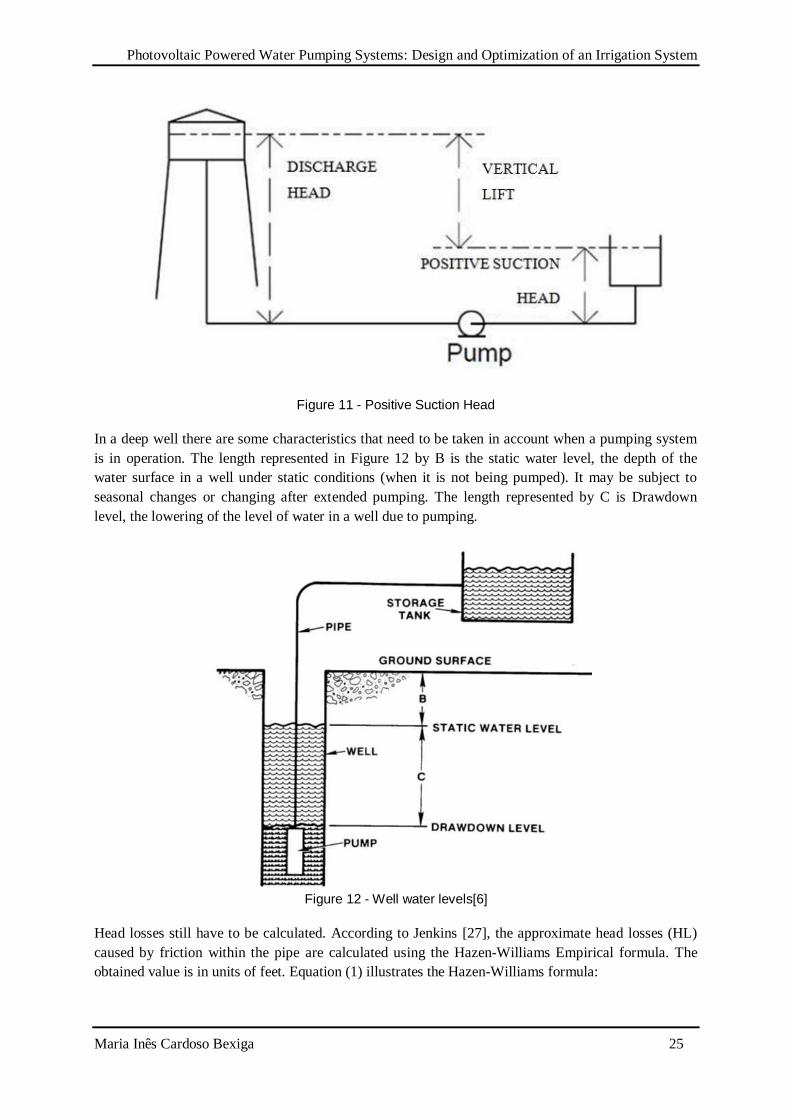
3.3.1. Total Dynamic Head (TDH)
Total dynamic head, or sometimes referred to as “Pumping Head”, is the total vertical lift plus head losses due to friction through the pipes. There are two situations to calculate total dynamic head: with
negative and positive suction head.
Figure 10 – Negative Suction Head
The vertical lift is the vertical distance that the water needs to be pumped, from the location of the
pump until the highest point where the water needs to be pumped. In Figure 10 (where there’s negative
suction head), the vertical lift is represented by discharge head plus negative suction head. When
suction head is positive (Figure 11) vertical lift will be the discharged head minus positive suction
head.
Photovoltaic Powered Water Pumping Systems: Design and Optimization of an Irrigation System
Maria Inês Cardoso Bexiga 25
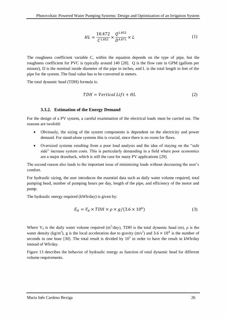
Figure 11 - Positive Suction Head
In a deep well there are some characteristics that need to be taken in account when a pumping system
is in operation. The length represented in Figure 12 by B is the static water level, the depth of the
water surface in a well under static conditions (when it is not being pumped). It may be subject to
seasonal changes or changing after extended pumping. The length represented by C is Drawdown
level, the lowering of the level of water in a well due to pumping.
Figure 12 - Well water levels[6]
Head losses still have to be calculated. According to Jenkins [27], the approximate head losses (HL)
caused by friction within the pipe are calculated using the Hazen-Williams Empirical formula. The
obtained value is in units of feet. Equation (1) illustrates the Hazen-Williams formula:
VERTICAL
LIFT
Photovoltaic Powered Water Pumping Systems: Design and Optimization of an Irrigation System
Maria Inês Cardoso Bexiga 26
(1)
The roughness coefficient variable C, within the equation depends on the type of pipe, but the
roughness coefficient for PVC is typically around 140 [28]. Q is the flow rate in GPM (gallons per
minute), D is the nominal inside diameter of the pipe in inches, and L is the total length in feet of the
pipe for the system. The final value has to be converted in meters.
The total dynamic head (TDH) formula is:
(2)
3.3.2. Estimation of the Energy Demand
For the design of a PV system, a careful examination of the electrical loads must be carried out. The
reasons are twofold:
Obviously, the sizing of the system components is dependent on the electricity and power
demand. For stand-alone systems this is crucial, since there is no room for flaws.
Oversized systems resulting from a poor load analysis and the idea of staying on the “safe
side” increase system costs. This is particularly demanding in a field where poor economics
are a major drawback, which is still the case for many PV applications [29].
The second reason also leads to the important issue of minimizing loads without decreasing the user’s
comfort.
For hydraulic sizing, the user introduces the essential data such as daily water volume required, total
pumping head, number of pumping hours per day, length of the pipe, and efficiency of the motor and
pump.
The hydraulic energy required (kWh/day) is given by:
(3)
Where Vd is the daily water volume required (m3/day), TDH is the total dynamic head (m), ρ is the
water density (kg/m3), g is the local acceleration due to gravity (m/s
2) and is the number of
seconds in one hour [30]. The total result is divided by 103 in order to have the result in kWh/day
instead of Wh/day.
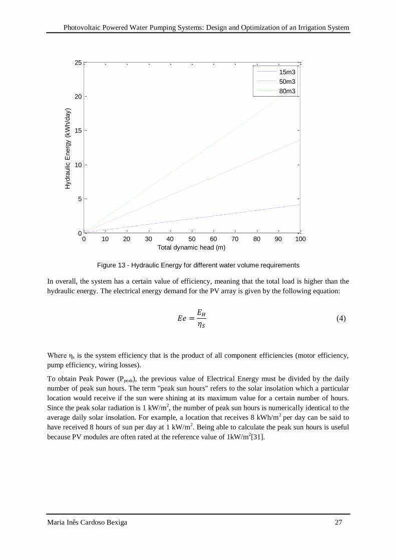
Figure 13 describes the behavior of hydraulic energy as function of total dynamic head for different
volume requirements.
Photovoltaic Powered Water Pumping Systems: Design and Optimization of an Irrigation System
Maria Inês Cardoso Bexiga 27
Figure 13 - Hydraulic Energy for different water volume requirements
In overall, the system has a certain value of efficiency, meaning that the total load is higher than the
hydraulic energy. The electrical energy demand for the PV array is given by the following equation:
(4)
Where ηs is the system efficiency that is the product of all component efficiencies (motor efficiency,
pump efficiency, wiring losses).
To obtain Peak Power (Ppeak), the previous value of Electrical Energy must be divided by the daily
number of peak sun hours. The term "peak sun hours" refers to the solar insolation which a particular
location would receive if the sun were shining at its maximum value for a certain number of hours.
Since the peak solar radiation is 1 kW/m2, the number of peak sun hours is numerically identical to the
average daily solar insolation. For example, a location that receives 8 kWh/m2 per day can be said to
have received 8 hours of sun per day at 1 kW/m2. Being able to calculate the peak sun hours is useful
because PV modules are often rated at the reference value of 1kW/m2[31].
0 10 20 30 40 50 60 70 80 90 1000
5
10
15
20
25
Total dynamic head (m)
Hydra
ulic
Energ
y (
kW
h/d
ay)
15m3
50m3
80m3
Photovoltaic Powered Water Pumping Systems: Design and Optimization of an Irrigation System
Maria Inês Cardoso Bexiga 28
3.4. Types of Pumps and pump selection
One of the major components of these systems is the pump. Conventional pumps use AC current
supplied utility lines or generators. Usually, solar pumps use DC current supplied by batteries and/or
PV panels. Also, they are designed to work effectively during low-light conditions, at reduced
voltage, without stalling (when the pump stops running, typically because of an overload) or
overheating.
Some solar pumps are fully submersible, while others are not. The use of submersible pumps
eliminates potential priming and freezing problems. Most solar water pumps are designed to use solar
power most efficiently and operate from 12 volts DC.
Water pumps can be split into two major categories: centrifugal pumps and positive displacement
pumps.
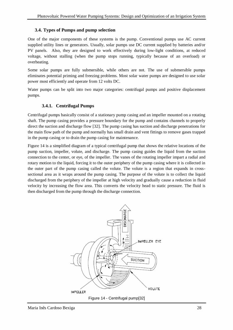
3.4.1. Centrifugal Pumps
Centrifugal pumps basically consist of a stationary pump casing and an impeller mounted on a rotating
shaft. The pump casing provides a pressure boundary for the pump and contains channels to properly
direct the suction and discharge flow [32]. The pump casing has suction and discharge penetrations for
the main flow path of the pump and normally has small drain and vent fittings to remove gases trapped
in the pump casing or to drain the pump casing for maintenance.
Figure 14 is a simplified diagram of a typical centrifugal pump that shows the relative locations of the
pump suction, impeller, volute, and discharge. The pump casing guides the liquid from the suction
connection to the center, or eye, of the impeller. The vanes of the rotating impeller impart a radial and
rotary motion to the liquid, forcing it to the outer periphery of the pump casing where it is collected in
the outer part of the pump casing called the volute. The volute is a region that expands in cross-
sectional area as it wraps around the pump casing. The purpose of the volute is to collect the liquid
discharged from the periphery of the impeller at high velocity and gradually cause a reduction in fluid
velocity by increasing the flow area. This converts the velocity head to static pressure. The fluid is
then discharged from the pump through the discharge connection.
Figure 14 - Centrifugal pump[32]
Photovoltaic Powered Water Pumping Systems: Design and Optimization of an Irrigation System
Maria Inês Cardoso Bexiga 29
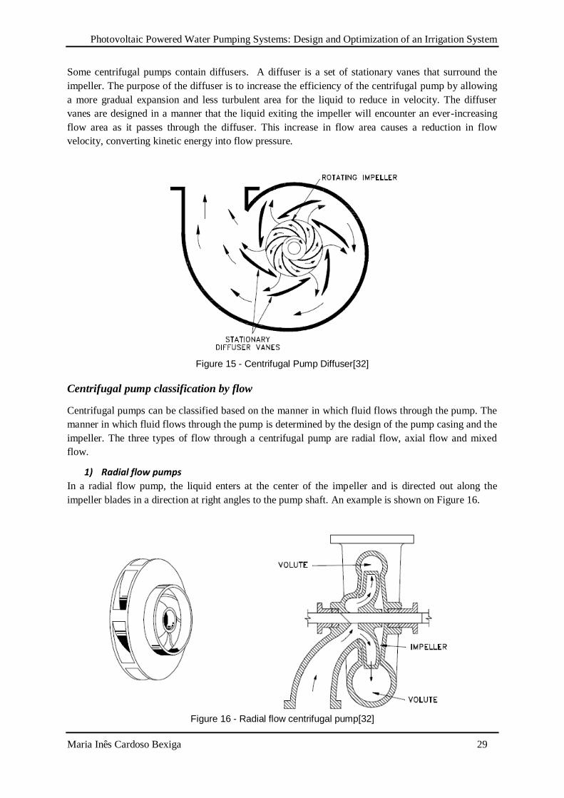
Some centrifugal pumps contain diffusers. A diffuser is a set of stationary vanes that surround the
impeller. The purpose of the diffuser is to increase the efficiency of the centrifugal pump by allowing
a more gradual expansion and less turbulent area for the liquid to reduce in velocity. The diffuser
vanes are designed in a manner that the liquid exiting the impeller will encounter an ever-increasing
flow area as it passes through the diffuser. This increase in flow area causes a reduction in flow
velocity, converting kinetic energy into flow pressure.
Figure 15 - Centrifugal Pump Diffuser[32]
Centrifugal pump classification by flow
Centrifugal pumps can be classified based on the manner in which fluid flows through the pump. The
manner in which fluid flows through the pump is determined by the design of the pump casing and the
impeller. The three types of flow through a centrifugal pump are radial flow, axial flow and mixed
flow.
1) Radial flow pumps
In a radial flow pump, the liquid enters at the center of the impeller and is directed out along the
impeller blades in a direction at right angles to the pump shaft. An example is shown on Figure 16.
Figure 16 - Radial flow centrifugal pump[32]
Photovoltaic Powered Water Pumping Systems: Design and Optimization of an Irrigation System
Maria Inês Cardoso Bexiga 30
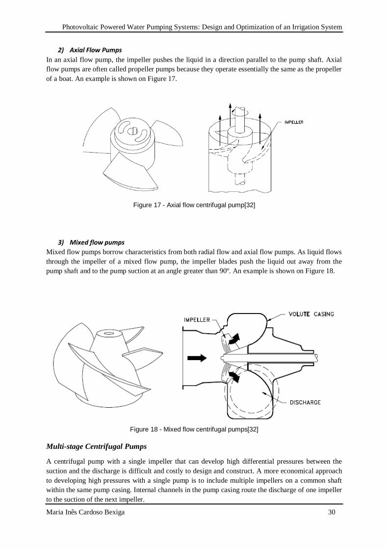
2) Axial Flow Pumps
In an axial flow pump, the impeller pushes the liquid in a direction parallel to the pump shaft. Axial
flow pumps are often called propeller pumps because they operate essentially the same as the propeller
of a boat. An example is shown on Figure 17.
Figure 17 - Axial flow centrifugal pump[32]
3) Mixed flow pumps
Mixed flow pumps borrow characteristics from both radial flow and axial flow pumps. As liquid flows
through the impeller of a mixed flow pump, the impeller blades push the liquid out away from the
pump shaft and to the pump suction at an angle greater than 90º. An example is shown on Figure 18.
Figure 18 - Mixed flow centrifugal pumps[32]
Multi-stage Centrifugal Pumps
A centrifugal pump with a single impeller that can develop high differential pressures between the
suction and the discharge is difficult and costly to design and construct. A more economical approach
to developing high pressures with a single pump is to include multiple impellers on a common shaft
within the same pump casing. Internal channels in the pump casing route the discharge of one impeller
to the suction of the next impeller.
Photovoltaic Powered Water Pumping Systems: Design and Optimization of an Irrigation System
Maria Inês Cardoso Bexiga 31
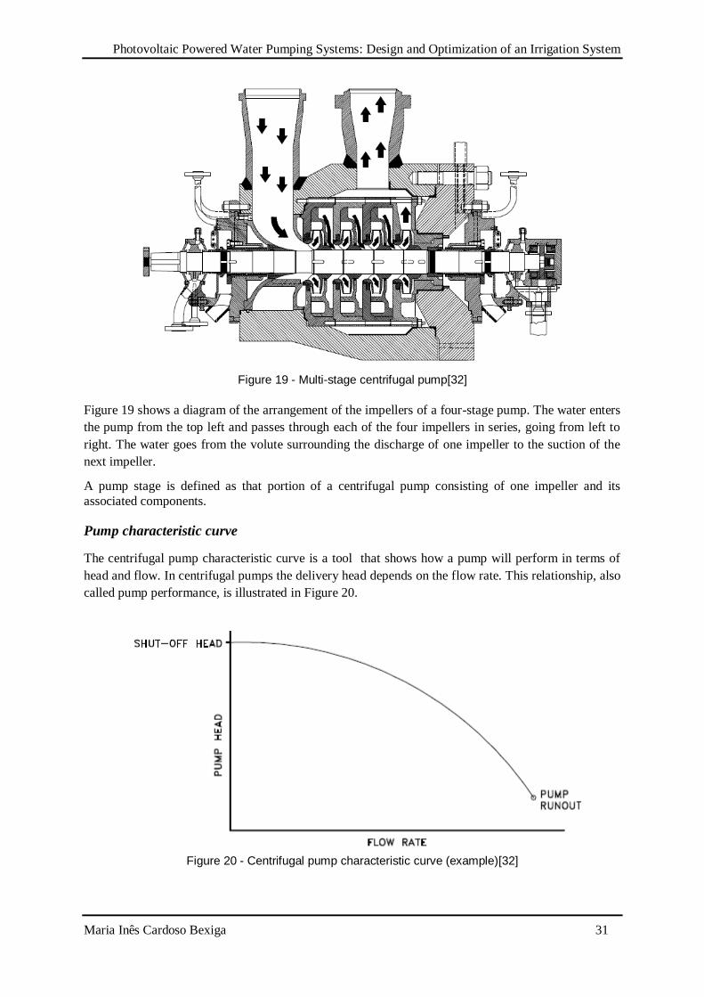
Figure 19 - Multi-stage centrifugal pump[32]
Figure 19 shows a diagram of the arrangement of the impellers of a four-stage pump. The water enters
the pump from the top left and passes through each of the four impellers in series, going from left to
right. The water goes from the volute surrounding the discharge of one impeller to the suction of the
next impeller.
A pump stage is defined as that portion of a centrifugal pump consisting of one impeller and its
associated components.
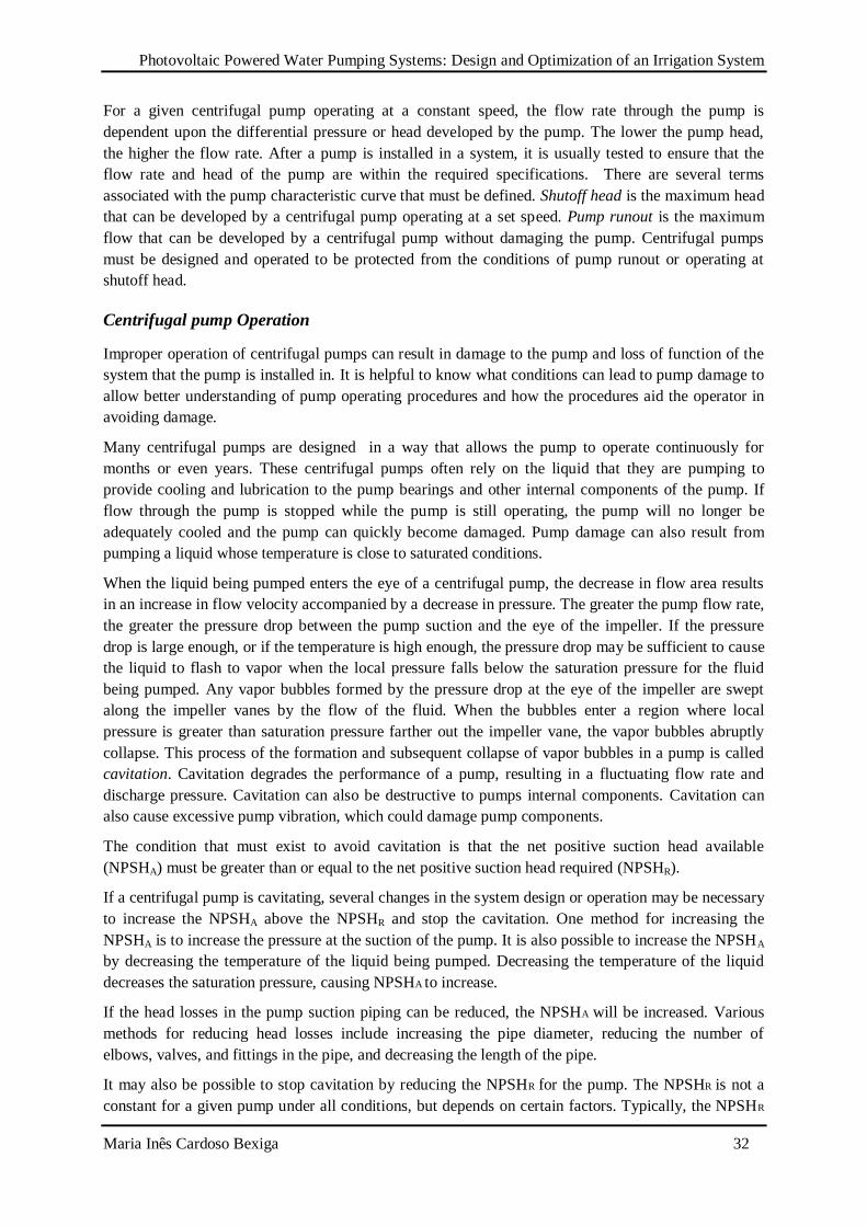
Pump characteristic curve
The centrifugal pump characteristic curve is a tool that shows how a pump will perform in terms of
head and flow. In centrifugal pumps the delivery head depends on the flow rate. This relationship, also
called pump performance, is illustrated in Figure 20.
Figure 20 - Centrifugal pump characteristic curve (example)[32]
Photovoltaic Powered Water Pumping Systems: Design and Optimization of an Irrigation System
Maria Inês Cardoso Bexiga 32
For a given centrifugal pump operating at a constant speed, the flow rate through the pump is
dependent upon the differential pressure or head developed by the pump. The lower the pump head,
the higher the flow rate. After a pump is installed in a system, it is usually tested to ensure that the
flow rate and head of the pump are within the required specifications. There are several terms
associated with the pump characteristic curve that must be defined. Shutoff head is the maximum head
that can be developed by a centrifugal pump operating at a set speed. Pump runout is the maximum
flow that can be developed by a centrifugal pump without damaging the pump. Centrifugal pumps
must be designed and operated to be protected from the conditions of pump runout or operating at
shutoff head.
Centrifugal pump Operation
Improper operation of centrifugal pumps can result in damage to the pump and loss of function of the
system that the pump is installed in. It is helpful to know what conditions can lead to pump damage to
allow better understanding of pump operating procedures and how the procedures aid the operator in
avoiding damage.
Many centrifugal pumps are designed in a way that allows the pump to operate continuously for
months or even years. These centrifugal pumps often rely on the liquid that they are pumping to
provide cooling and lubrication to the pump bearings and other internal components of the pump. If
flow through the pump is stopped while the pump is still operating, the pump will no longer be
adequately cooled and the pump can quickly become damaged. Pump damage can also result from
pumping a liquid whose temperature is close to saturated conditions.
When the liquid being pumped enters the eye of a centrifugal pump, the decrease in flow area results
in an increase in flow velocity accompanied by a decrease in pressure. The greater the pump flow rate,
the greater the pressure drop between the pump suction and the eye of the impeller. If the pressure
drop is large enough, or if the temperature is high enough, the pressure drop may be sufficient to cause
the liquid to flash to vapor when the local pressure falls below the saturation pressure for the fluid
being pumped. Any vapor bubbles formed by the pressure drop at the eye of the impeller are swept
along the impeller vanes by the flow of the fluid. When the bubbles enter a region where local
pressure is greater than saturation pressure farther out the impeller vane, the vapor bubbles abruptly
collapse. This process of the formation and subsequent collapse of vapor bubbles in a pump is called
cavitation. Cavitation degrades the performance of a pump, resulting in a fluctuating flow rate and
discharge pressure. Cavitation can also be destructive to pumps internal components. Cavitation can
also cause excessive pump vibration, which could damage pump components.
The condition that must exist to avoid cavitation is that the net positive suction head available
(NPSHA) must be greater than or equal to the net positive suction head required (NPSHR).
If a centrifugal pump is cavitating, several changes in the system design or operation may be necessary
to increase the NPSHA above the NPSHR and stop the cavitation. One method for increasing the
NPSHA is to increase the pressure at the suction of the pump. It is also possible to increase the NPSHA
by decreasing the temperature of the liquid being pumped. Decreasing the temperature of the liquid
decreases the saturation pressure, causing NPSHA to increase.
If the head losses in the pump suction piping can be reduced, the NPSHA will be increased. Various
methods for reducing head losses include increasing the pipe diameter, reducing the number of
elbows, valves, and fittings in the pipe, and decreasing the length of the pipe.
It may also be possible to stop cavitation by reducing the NPSHR for the pump. The NPSHR is not a
constant for a given pump under all conditions, but depends on certain factors. Typically, the NPSHR
Photovoltaic Powered Water Pumping Systems: Design and Optimization of an Irrigation System
Maria Inês Cardoso Bexiga 33
of a pump increases significantly as flow rate through the pump increases. Therefore, reducing the
flow rate through a pump by throttling a discharge valve decreases NPSHR. NPSHR is also dependent
upon pump speed. The faster the impeller of a pump rotates, the greater the NPSHR. Therefore, if the
speed of a variable speed centrifugal pump is reduced, the NPSHR of the pump decreases. However,
since a pump's flow rate is most often dictated by the needs of the system on which it is connected to,
only limited adjustments can be made without starting additional parallel pumps, if available.
The net positive suction head required to prevent cavitation is determined through testing by the pump
manufacturer and depends upon factors including the type of impeller inlet, impeller design, pump
flow rate, impeller rotational speed, and the type of liquid being pumped. The manufacturer typically
supplies curves of NPSHR as a function of pump flow rate for a particular liquid (usually water) in the
vendor manual for the pump.
3.4.2. Positive displacement pumps
Positive displacement pumps (PD) operate on a different principle than centrifugal pumps. Positive
displacement pumps physically entrap a quantity of liquid at the suction of the pump and push that
quantity out the discharge of pump.
According to [32], a positive displacement pump is one in which a definite volume of liquid is
delivered for each cycle of pump operation. This volume is constant regardless of the resistance to
flow offered by the system the pump is in, provided the capacity of the power unit driving the pump or
pump component strength limits are not exceeded. The positive displacement pump differs from
centrifugal pumps, which deliver a continuous flow for any given pump speed and discharge
resistance.
Positive displacement pumps can be grouped into three basic categories based on their design and
operation. The three groups are reciprocating pumps, rotary pumps, and diaphragm pumps.
All positive displacement pumps operate on the same basic principle. This principle can be most easily
demonstrated by considering a reciprocating positive displacement pump consisting of a single
reciprocating piston in a cylinder with a single suction port and a single discharge port as shown in
Figure 21. Check valves in the suction and discharge ports allow flow in only one direction.
Figure 21 - Reciprocating Positive Displacement Pump Operation[32]
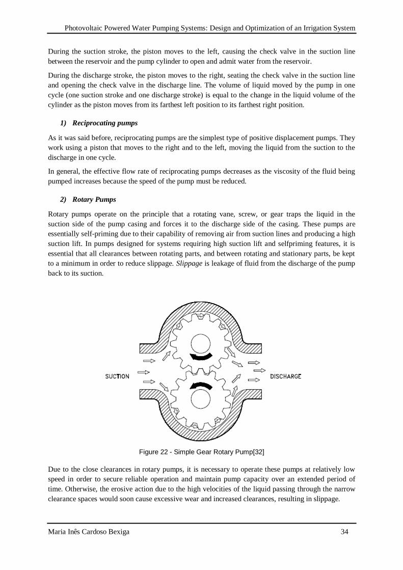
Photovoltaic Powered Water Pumping Systems: Design and Optimization of an Irrigation System
Maria Inês Cardoso Bexiga 34
During the suction stroke, the piston moves to the left, causing the check valve in the suction line
between the reservoir and the pump cylinder to open and admit water from the reservoir.
During the discharge stroke, the piston moves to the right, seating the check valve in the suction line
and opening the check valve in the discharge line. The volume of liquid moved by the pump in one
cycle (one suction stroke and one discharge stroke) is equal to the change in the liquid volume of the
cylinder as the piston moves from its farthest left position to its farthest right position.
1) Reciprocating pumps
As it was said before, reciprocating pumps are the simplest type of positive displacement pumps. They
work using a piston that moves to the right and to the left, moving the liquid from the suction to the
discharge in one cycle.
In general, the effective flow rate of reciprocating pumps decreases as the viscosity of the fluid being
pumped increases because the speed of the pump must be reduced.
2) Rotary Pumps
Rotary pumps operate on the principle that a rotating vane, screw, or gear traps the liquid in the
suction side of the pump casing and forces it to the discharge side of the casing. These pumps are
essentially self-priming due to their capability of removing air from suction lines and producing a high
suction lift. In pumps designed for systems requiring high suction lift and selfpriming features, it is
essential that all clearances between rotating parts, and between rotating and stationary parts, be kept
to a minimum in order to reduce slippage. Slippage is leakage of fluid from the discharge of the pump
back to its suction.
Figure 22 - Simple Gear Rotary Pump[32]
Due to the close clearances in rotary pumps, it is necessary to operate these pumps at relatively low
speed in order to secure reliable operation and maintain pump capacity over an extended period of
time. Otherwise, the erosive action due to the high velocities of the liquid passing through the narrow
clearance spaces would soon cause excessive wear and increased clearances, resulting in slippage.
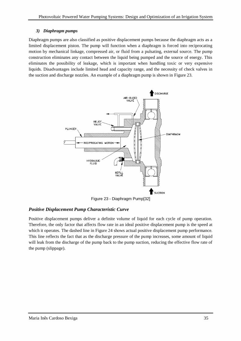
Photovoltaic Powered Water Pumping Systems: Design and Optimization of an Irrigation System
Maria Inês Cardoso Bexiga 35
3) Diaphragm pumps
Diaphragm pumps are also classified as positive displacement pumps because the diaphragm acts as a
limited displacement piston. The pump will function when a diaphragm is forced into reciprocating
motion by mechanical linkage, compressed air, or fluid from a pulsating, external source. The pump
construction eliminates any contact between the liquid being pumped and the source of energy. This
eliminates the possibility of leakage, which is important when handling toxic or very expensive
liquids. Disadvantages include limited head and capacity range, and the necessity of check valves in
the suction and discharge nozzles. An example of a diaphragm pump is shown in Figure 23.
Figure 23 - Diaphragm Pump[32]
Positive Displacement Pump Characteristic Curve
Positive displacement pumps deliver a definite volume of liquid for each cycle of pump operation.
Therefore, the only factor that affects flow rate in an ideal positive displacement pump is the speed at
which it operates. The dashed line in Figure 24 shows actual positive displacement pump performance.
This line reflects the fact that as the discharge pressure of the pump increases, some amount of liquid
will leak from the discharge of the pump back to the pump suction, reducing the effective flow rate of
the pump (slippage).
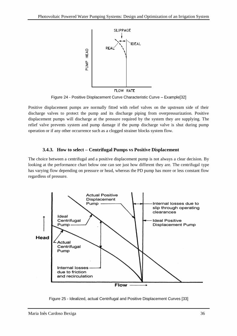
Photovoltaic Powered Water Pumping Systems: Design and Optimization of an Irrigation System
Maria Inês Cardoso Bexiga 36
Figure 24 - Positive Displacement Curve Characteristic Curve – Example[32]
Positive displacement pumps are normally fitted with relief valves on the upstream side of their
discharge valves to protect the pump and its discharge piping from overpressurization. Positive
displacement pumps will discharge at the pressure required by the system they are supplying. The
relief valve prevents system and pump damage if the pump discharge valve is shut during pump
operation or if any other occurrence such as a clogged strainer blocks system flow.
3.4.3. How to select – Centrifugal Pumps vs Positive Displacement
The choice between a centrifugal and a positive displacement pump is not always a clear decision. By
looking at the performance chart below one can see just how different they are. The centrifugal type
has varying flow depending on pressure or head, whereas the PD pump has more or less constant flow
regardless of pressure.
Figure 25 - Idealized, actual Centrifugal and Positive Displacement Curves [33]
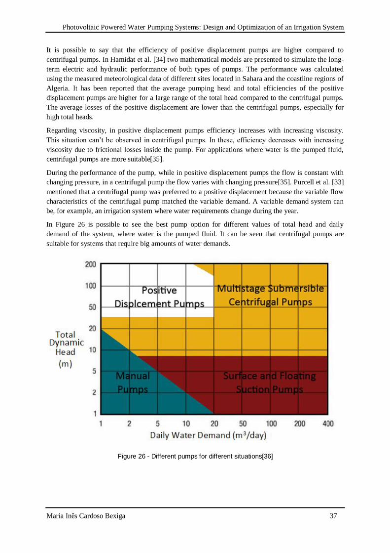
Photovoltaic Powered Water Pumping Systems: Design and Optimization of an Irrigation System
Maria Inês Cardoso Bexiga 37
It is possible to say that the efficiency of positive displacement pumps are higher compared to
centrifugal pumps. In Hamidat et al. [34] two mathematical models are presented to simulate the long-
term electric and hydraulic performance of both types of pumps. The performance was calculated
using the measured meteorological data of different sites located in Sahara and the coastline regions of
Algeria. It has been reported that the average pumping head and total efficiencies of the positive
displacement pumps are higher for a large range of the total head compared to the centrifugal pumps.
The average losses of the positive displacement are lower than the centrifugal pumps, especially for
high total heads.
Regarding viscosity, in positive displacement pumps efficiency increases with increasing viscosity.
This situation can’t be observed in centrifugal pumps. In these, efficiency decreases with increasing
viscosity due to frictional losses inside the pump. For applications where water is the pumped fluid,
centrifugal pumps are more suitable[35].
During the performance of the pump, while in positive displacement pumps the flow is constant with
changing pressure, in a centrifugal pump the flow varies with changing pressure[35]. Purcell et al. [33]
mentioned that a centrifugal pump was preferred to a positive displacement because the variable flow
characteristics of the centrifugal pump matched the variable demand. A variable demand system can
be, for example, an irrigation system where water requirements change during the year.
In Figure 26 is possible to see the best pump option for different values of total head and daily
demand of the system, where water is the pumped fluid. It can be seen that centrifugal pumps are
suitable for systems that require big amounts of water demands.
Figure 26 - Different pumps for different situations[36]
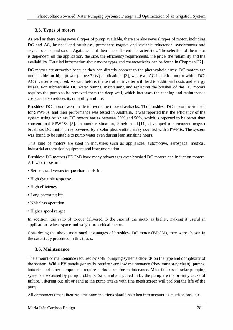
Photovoltaic Powered Water Pumping Systems: Design and Optimization of an Irrigation System
Maria Inês Cardoso Bexiga 38
3.5. Types of motors
As well as there being several types of pump available, there are also several types of motor, including
DC and AC, brushed and brushless, permanent magnet and variable reluctance, synchronous and
asynchronous, and so on. Again, each of them has different characteristics. The selection of the motor
is dependent on the application, the size, the efficiency requirements, the price, the reliability and the
availability. Detailed information about motor types and characteristics can be found in Chapman[37].
DC motors are attractive because they can directly connect to the photovoltaic array. DC motors are
not suitable for high power (above 7kW) applications [3], where an AC induction motor with a DC-
AC inverter is required. As said before, the use of an inverter will lead to additional costs and energy
losses. For submersible DC water pumps, maintaining and replacing the brushes of the DC motors
requires the pump to be removed from the deep well, which increases the running and maintenance
costs and also reduces its reliability and life.
Brushless DC motors were made to overcome these drawbacks. The brushless DC motors were used
for SPWPSs, and their performance was tested in Australia. It was reported that the efficiency of the
system using brushless DC motors varies between 30% and 50%, which is reported to be better than
conventional SPWPSs [3]. In another situation, Singh et al.[11] developed a permanent magnet
brushless DC motor drive powered by a solar photovoltaic array coupled with SPWPSs. The system
was found to be suitable to pump water even during lean sunshine hours.
This kind of motors are used in industries such as appliances, automotive, aerospace, medical,
industrial automation equipment and instrumentation.
Brushless DC motors (BDCM) have many advantages over brushed DC motors and induction motors.
A few of these are:
• Better speed versus torque characteristics
• High dynamic response
• High efficiency
• Long operating life
• Noiseless operation
• Higher speed ranges
In addition, the ratio of torque delivered to the size of the motor is higher, making it useful in
applications where space and weight are critical factors.
Considering the above mentioned advantages of brushless DC motor (BDCM), they were chosen in
the case study presented in this thesis.
3.6. Maintenance
The amount of maintenance required by solar pumping systems depends on the type and complexity of
the system. While PV panels generally require very low maintenance (they must stay clean), pumps,
batteries and other components require periodic routine maintenance. Most failures of solar pumping
systems are caused by pump problems. Sand and silt pulled in by the pump are the primary cause of
failure. Filtering out silt or sand at the pump intake with fine mesh screen will prolong the life of the
pump.
All components manufacturer’s recommendations should be taken into account as much as possible.
Photovoltaic Powered Water Pumping Systems: Design and Optimization of an Irrigation System
Maria Inês Cardoso Bexiga 39
3.7. Limitations of Solar Powered Water Pumping Systems
Because we are talking about renewable energy and new technologies, there are several limitations on
this kind of systems.
The first limitation is obvious. The performance of the system is highly influenced by fluctuations in
the solar intensity [26]. For this reason, the use of a storage tank or a battery bank is important. This
dependence on solar radiation might be a problem or not since most of the water demand is in the
summer, when solar radiation reaches higher values throughout the year.
Considering factors that lead to energy efficiency decrease, temperature rise in photovoltaic cells
during operation affects their energy output [3]. Dust accumulation over the solar module affects also
energy output. The energy output can be decreased up to 30% within a few weeks of installation [38].
In [39], it is shown that each of these three factors - dust accumulation, ambient relative humidity and
air velocity - affect energy output and energy efficiency.
Finally, the development of SPWPSs could be faster if proper financing schemes were conducted.
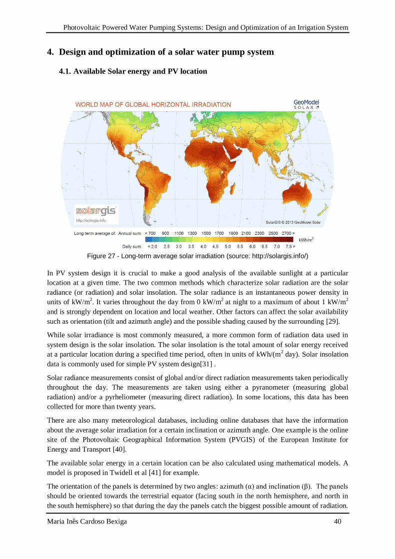
Photovoltaic Powered Water Pumping Systems: Design and Optimization of an Irrigation System
Maria Inês Cardoso Bexiga 40
4. Design and optimization of a solar water pump system
4.1. Available Solar energy and PV location
Figure 27 - Long-term average solar irradiation (source: http://solargis.info/)
In PV system design it is crucial to make a good analysis of the available sunlight at a particular
location at a given time. The two common methods which characterize solar radiation are the solar
radiance (or radiation) and solar insolation. The solar radiance is an instantaneous power density in
units of kW/m2. It varies throughout the day from 0 kW/m
2 at night to a maximum of about 1 kW/m
2
and is strongly dependent on location and local weather. Other factors can affect the solar availability
such as orientation (tilt and azimuth angle) and the possible shading caused by the surrounding [29].
While solar irradiance is most commonly measured, a more common form of radiation data used in
system design is the solar insolation. The solar insolation is the total amount of solar energy received
at a particular location during a specified time period, often in units of kWh/(m2 day). Solar insolation
data is commonly used for simple PV system design[31] .
Solar radiance measurements consist of global and/or direct radiation measurements taken periodically
throughout the day. The measurements are taken using either a pyranometer (measuring global
radiation) and/or a pyrheliometer (measuring direct radiation). In some locations, this data has been
collected for more than twenty years.
There are also many meteorological databases, including online databases that have the information
about the average solar irradiation for a certain inclination or azimuth angle. One example is the online
site of the Photovoltaic Geographical Information System (PVGIS) of the European Institute for
Energy and Transport [40].
The available solar energy in a certain location can be also calculated using mathematical models. A
model is proposed in Twidell et al [41] for example.
The orientation of the panels is determined by two angles: azimuth (α) and inclination (β). The panels
should be oriented towards the terrestrial equator (facing south in the north hemisphere, and north in
the south hemisphere) so that during the day the panels catch the biggest possible amount of radiation.
Photovoltaic Powered Water Pumping Systems: Design and Optimization of an Irrigation System
Maria Inês Cardoso Bexiga 41
For that reason, α=0 [42]. The inclination angles changes for different applications. For installations
with constant or similar consumptions throughout the year, it is better to optimize the installation to
capture maximum energy in the winter, so the inclination should be the absolute value of the latitude
plus 10º. For installations with inferior consumptions in winter the value of the latitude of the place
can be used as the solar panel inclination. For installations that are only used during summer, the value
of the inclination should be the latitude angles decreased in 10º [42].
4.2. Water requirement
The first step in the design of a PV water pumping system is to determine the volume of water per day
and how far the water is to be transported. It is worth mentioning that predictions of water
consumption involve some uncertainty. This uncertainty can be reduced whenever important
parameters such as such as population, location and other factors are known accurately.
Human and animal needs can be estimated by multiplying the daily usage by the population.
It is complicated to estimate water needs for humans because water usage varies based on village size,
location and lifestyle. For planning the introduction of mechanical pumping systems into a village a
daily usage of 40 liters/person/day is suggested as a reference value. For a larger town, where indoor
toilets and showers are more common, a daily usage of 100 liters/person/day is often used [6].
Even more complex, is to estimate the water requirements for irrigation applications. In this case,
water requirements are depending on the type of soil, how clean is the soil, season and the amount of
water that the plants loose through evapotranspiration. The amount of water required to irrigation will
be the difference between evapotranspiration and precipitation.
4.3. Water source
The configuration of the water system will be first defined by the type of water source used, as well as
by the local topography and the location of the delivery point. The water source could be either
subsurface (a well) , surface (a pond) or deep water. For different water sources, there is a specific
type of motor-pumps assembly to use as described in previous sections.
In a surface source, the water availability can vary seasonally. For example, the amount and quality of
the water can be low during the summer when it is needed the most.
4.4. Method for optimal PV pumping system
Introduction to the method
We consider here a DC-PV pumping system and present a multistep optimization method for its
efficient utilization. The analysis of a DC-PV pumping system is extremely complex since volumetric
rate of pumped water is dependent on many factors, which can be described by highly nonlinear
equations. These factors can be classified as meteorological parameters (radiation intensity and
ambient temperature) of the site, PV array specifications (I-V output, area, conversion efficiency, and
slope), and DC motor-pump-hydraulic system characteristics (I-V output of the motor-pump assembly,
static and dynamic head of pipeline).
In a PV Water Pumping system, the operating point depends on the current-voltage (I-V)
characteristics of both the motor-pump assembly and the PV array. I-V characteristics of the PV array
varies nonlinearly with solar radiation, ambient temperature, and the current drawn by the DC motor.
Photovoltaic Powered Water Pumping Systems: Design and Optimization of an Irrigation System
Maria Inês Cardoso Bexiga 42
For a given solar radiation and ambient temperature, there is a unique point on the IV curve of the PV
array at which the power output is maximum. This point is known as Maximum Power Point (MPP).
Depending on the motor-pump assembly used in each system, there is an Equilibrium Operation Point
(EOP). For a certain radiation, this point results on the intersection of the I-V characteristic of the PV
array and the motor-pump assembly. The main goal of the method is to decrease the difference
between both curves (MPP curve and EOP curve) for several levels of radiation. This way, it is
possible to optimize direct-coupled system’s utilization.
PV array
The PV module is a nonlinear device and can be described by its I-V characteristic. Assuming
identical PV cells, the I-V characteristic of the PV model is obtained, depending of course on the
global irradiance and temperature. The operation point of the system (PV array coupled with the
motor-pump assembly) changes whenever any of these parameters changes.
There are several mathematical models which describe the I-V characteristic that can be distinguished
by the calculation procedure, the number of intervening parameters and the accuracy of results [34].
Equation (5) describes the I-V characteristics of a solar cell:
(5)
Where IL is the photocurrent, I0 is the reverse saturation current, T the cell temperature, K the
Boltzmann’s constant, q the charge of an electron and A the p-n junction ideality factor [43]. The
factor A in equation (5) determines the cell deviation from the ideal p-n junction characteristics (A=1).
For commercial cells, the ideality factor can vary from 1 to 2.5[43].
The cell reverse saturation current I0 varies with temperature according to the following equation [43]:
(6)
Where Tr is the cell reference temperature, Irr is the reverse saturation current at Tr, EG is the band gap
of the semiconductor used in the cell. The bang gap decreases with temperature and its temperature
dependence is well modeled by:
(7)
Where α and β are constants specific to each semiconductor[44]. The photocurrent IL depends on solar
radiation and cell temperature as follows:
(8)
Where Iscr is the cell short-circuit current at reference temperature and radiation, Ki is the short circuit
current temperature coefficient and S is the solar radiation in mW/cm2[43].
In order to determine operating points of the system, I-V relation for the motor-pump assembly is also
necessary.
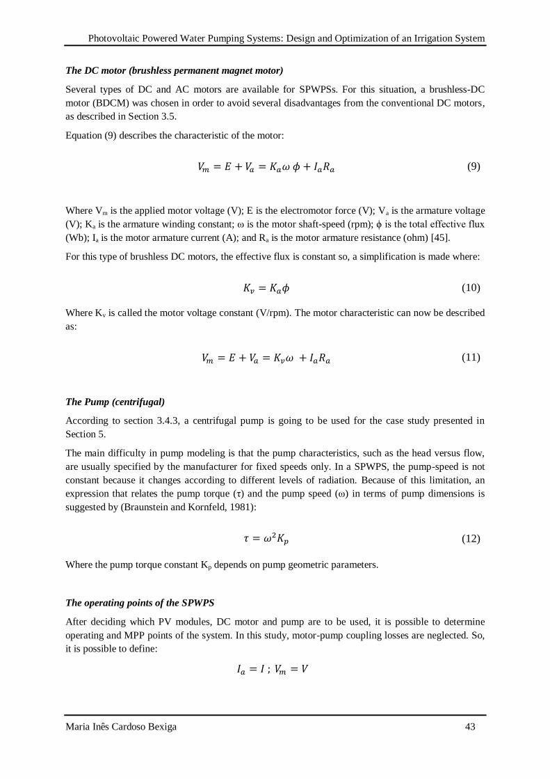
Photovoltaic Powered Water Pumping Systems: Design and Optimization of an Irrigation System
Maria Inês Cardoso Bexiga 43
The DC motor (brushless permanent magnet motor)
Several types of DC and AC motors are available for SPWPSs. For this situation, a brushless-DC
motor (BDCM) was chosen in order to avoid several disadvantages from the conventional DC motors,
as described in Section 3.5.
Equation (9) describes the characteristic of the motor:
(9)
Where Vm is the applied motor voltage (V); E is the electromotor force (V); Va is the armature voltage
(V); Ka is the armature winding constant; ω is the motor shaft-speed (rpm); ϕ is the total effective flux
(Wb); Ia is the motor armature current (A); and Ra is the motor armature resistance (ohm) [45].
For this type of brushless DC motors, the effective flux is constant so, a simplification is made where:
(10)
Where Kv is called the motor voltage constant (V/rpm). The motor characteristic can now be described
as:
(11)
The Pump (centrifugal)
According to section 3.4.3, a centrifugal pump is going to be used for the case study presented in
Section 5.
The main difficulty in pump modeling is that the pump characteristics, such as the head versus flow,
are usually specified by the manufacturer for fixed speeds only. In a SPWPS, the pump-speed is not
constant because it changes according to different levels of radiation. Because of this limitation, an
expression that relates the pump torque (τ) and the pump speed (ω) in terms of pump dimensions is
suggested by (Braunstein and Kornfeld, 1981):
(12)
Where the pump torque constant Kp depends on pump geometric parameters.
The operating points of the SPWPS
After deciding which PV modules, DC motor and pump are to be used, it is possible to determine
operating and MPP points of the system. In this study, motor-pump coupling losses are neglected. So,
it is possible to define:
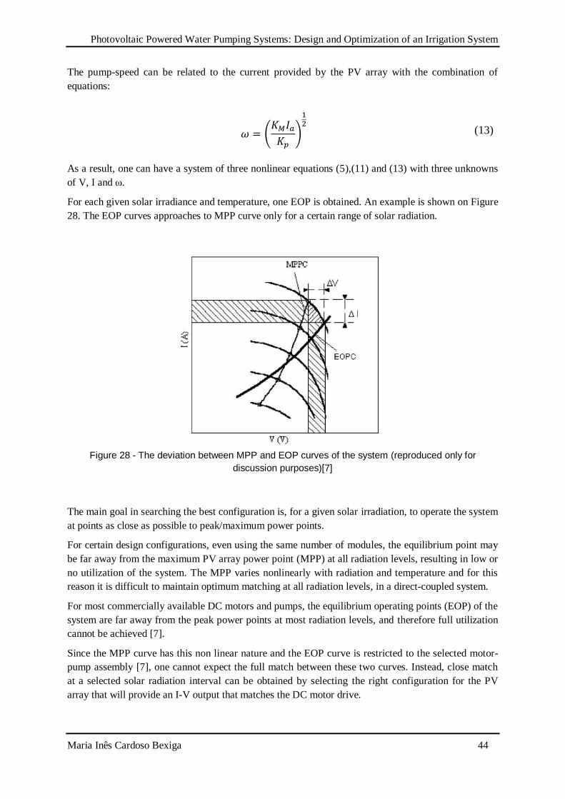
Photovoltaic Powered Water Pumping Systems: Design and Optimization of an Irrigation System
Maria Inês Cardoso Bexiga 44
The pump-speed can be related to the current provided by the PV array with the combination of
equations:
(13)
As a result, one can have a system of three nonlinear equations (5),(11) and (13) with three unknowns
of V, I and ω.
For each given solar irradiance and temperature, one EOP is obtained. An example is shown on Figure
28. The EOP curves approaches to MPP curve only for a certain range of solar radiation.
Figure 28 - The deviation between MPP and EOP curves of the system (reproduced only for
discussion purposes)[7]
The main goal in searching the best configuration is, for a given solar irradiation, to operate the system
at points as close as possible to peak/maximum power points.
For certain design configurations, even using the same number of modules, the equilibrium point may
be far away from the maximum PV array power point (MPP) at all radiation levels, resulting in low or
no utilization of the system. The MPP varies nonlinearly with radiation and temperature and for this
reason it is difficult to maintain optimum matching at all radiation levels, in a direct-coupled system.
For most commercially available DC motors and pumps, the equilibrium operating points (EOP) of the
system are far away from the peak power points at most radiation levels, and therefore full utilization
cannot be achieved [7].
Since the MPP curve has this non linear nature and the EOP curve is restricted to the selected motor-
pump assembly [7], one cannot expect the full match between these two curves. Instead, close match
at a selected solar radiation interval can be obtained by selecting the right configuration for the PV
array that will provide an I-V output that matches the DC motor drive.
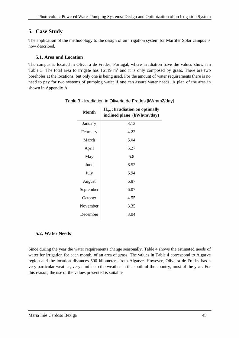
Photovoltaic Powered Water Pumping Systems: Design and Optimization of an Irrigation System
Maria Inês Cardoso Bexiga 45
5. Case Study
The application of the methodology to the design of an irrigation system for Martifer Solar campus is
now described.
5.1. Area and Location
The campus is located in Oliveira de Frades, Portugal, where irradiation have the values shown in
Table 3. The total area to irrigate has 16119 m2 and it is only composed by grass. There are two
boreholes at the locations, but only one is being used. For the amount of water requirements there is no
need to pay for two systems of pumping water if one can assure water needs. A plan of the area in
shown in Appendix A.
Table 3 - Irradiation in Oliveria de Frades [kWh/m2/day]
Month Hopt :Irradiation on optimally
inclined plane (kWh/m2/day)
January 3.13
February 4.22
March 5.04
April 5.27
May 5.8
June 6.52
July 6.94
August 6.87
September 6.07
October 4.55
November 3.35
December 3.04
5.2. Water Needs
Since during the year the water requirements change seasonally, Table 4 shows the estimated needs of
water for irrigation for each month, of an area of grass. The values in Table 4 correspond to Algarve
region and the location distances 500 kilometers from Algarve. However, Oliveira de Frades has a
very particular weather, very similar to the weather in the south of the country, most of the year. For
this reason, the use of the values presented is suitable.

Photovoltaic Powered Water Pumping Systems: Design and Optimization of an Irrigation System
Maria Inês Cardoso Bexiga 46
Table 4 - Water needs for grass [46]
Month Irrigation (l/m2/day) Irrigation (l/day) Irrigation (m
3/day)
January 0.95 15313 15.313
February 1.34 21599 21.599
March 2.01 32399 32.399
April 2.91 46906 46.906
May 3.52 56739 56.739
June 4.59 73986 73.986
July 4.92 79305 79.305
August 4.36 70279 70.279
September 3.3 53193 53.193
October 2.07 33366 33.366
November 1.18 19020 19.020
December 1 16119 16.119
As can be seen on the next figure, one of the main advantages of this kind of system is that water
demand changes seasonally in a similar way as irradiation. Levels of radiation were estimated with
α=0º and β=34º. Optimum inclination angle was determined by PV GIS.
Figure 29 - Irradiation and Daily Irrigation
0
10
20
30
40
50
60
70
80
90
0
1
2
3
4
5
6
7
8
1 3 5 7 9 11
Dai
ly Ir
riga
tio
n [
m3
/day
]
Irra
dia
tio
n [
kWh
/m2
/day
]
Month
Irradiation
Daily Irrigation
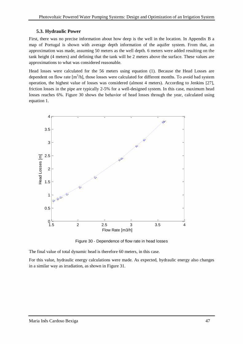
Photovoltaic Powered Water Pumping Systems: Design and Optimization of an Irrigation System
Maria Inês Cardoso Bexiga 47
5.3. Hydraulic Power
First, there was no precise information about how deep is the well in the location. In Appendix B a
map of Portugal is shown with average depth information of the aquifer system. From that, an
approximation was made, assuming 50 meters as the well depth. 6 meters were added resulting on the
tank height (4 meters) and defining that the tank will be 2 meters above the surface. These values are
approximations to what was considered reasonable.
Head losses were calculated for the 56 meters using equation (1). Because the Head Losses are
dependent on flow rate [m3/h], those losses were calculated for different months. To avoid bad system
operation, the highest value of losses was considered (almost 4 meters). According to Jenkins [27],
friction losses in the pipe are typically 2-5% for a well-designed system. In this case, maximum head
losses reaches 6%. Figure 30 shows the behavior of head losses through the year, calculated using
equation 1.
Figure 30 - Dependence of flow rate in head losses
The final value of total dynamic head is therefore 60 meters, in this case.
For this value, hydraulic energy calculations were made. As expected, hydraulic energy also changes
in a similar way as irradiation, as shown in Figure 31.
1.5 2 2.5 3 3.5 40
0.5
1
1.5
2
2.5
3
3.5
4
Flow Rate [m3/h]
Head L
osses [
m]
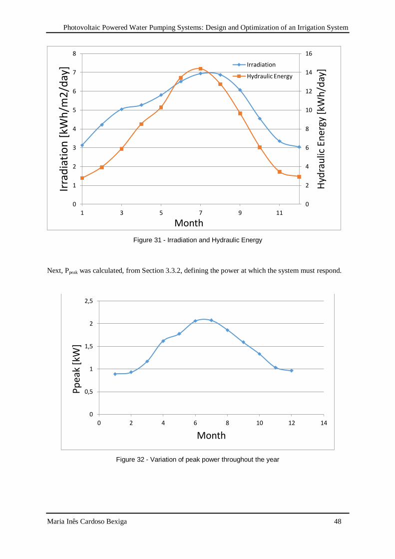
Photovoltaic Powered Water Pumping Systems: Design and Optimization of an Irrigation System
Maria Inês Cardoso Bexiga 48
Figure 31 - Irradiation and Hydraulic Energy
Next, Ppeak was calculated, from Section 3.3.2, defining the power at which the system must respond.
Figure 32 - Variation of peak power throughout the year
0
2
4
6
8
10
12
14
16
0
1
2
3
4
5
6
7
8
1 3 5 7 9 11
Hyd
rau
lic E
ner
gy [
kWh
/day
]
Irra
dia
tio
n [
kWh
/m2
/day
]
Month
Irradiation
Hydraulic Energy
0
0,5
1
1,5
2
2,5
0 2 4 6 8 10 12 14
Pp
eak
[kW
]
Month
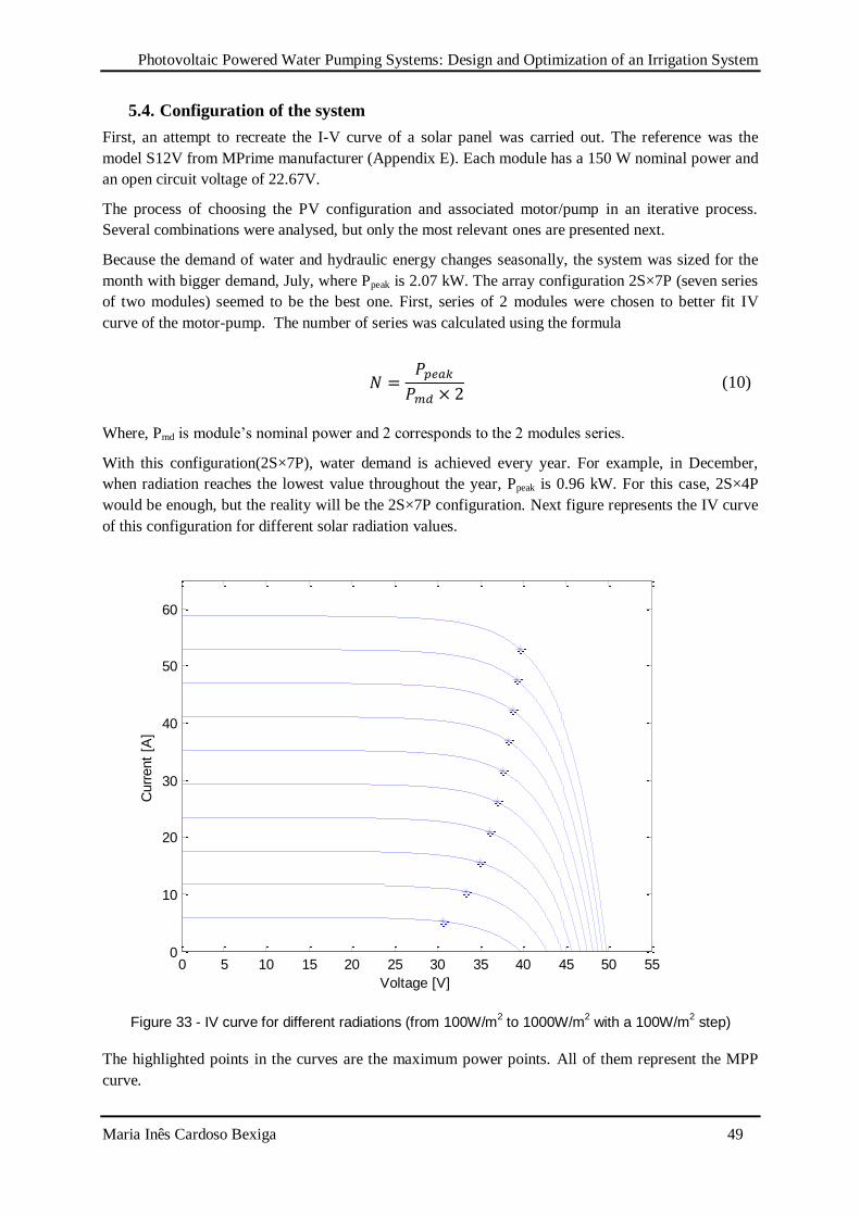
Photovoltaic Powered Water Pumping Systems: Design and Optimization of an Irrigation System
Maria Inês Cardoso Bexiga 49
5.4. Configuration of the system
First, an attempt to recreate the I-V curve of a solar panel was carried out. The reference was the
model S12V from MPrime manufacturer (Appendix E). Each module has a 150 W nominal power and
an open circuit voltage of 22.67V.
The process of choosing the PV configuration and associated motor/pump in an iterative process.
Several combinations were analysed, but only the most relevant ones are presented next.
Because the demand of water and hydraulic energy changes seasonally, the system was sized for the
month with bigger demand, July, where Ppeak is 2.07 kW. The array configuration 2S×7P (seven series
of two modules) seemed to be the best one. First, series of 2 modules were chosen to better fit IV
curve of the motor-pump. The number of series was calculated using the formula
(10)
Where, Pmd is module’s nominal power and 2 corresponds to the 2 modules series.
With this configuration(2S×7P), water demand is achieved every year. For example, in December,
when radiation reaches the lowest value throughout the year, Ppeak is 0.96 kW. For this case, 2S×4P
would be enough, but the reality will be the 2S×7P configuration. Next figure represents the IV curve
of this configuration for different solar radiation values.
Figure 33 - IV curve for different radiations (from 100W/m2 to 1000W/m
2 with a 100W/m
2 step)
The highlighted points in the curves are the maximum power points. All of them represent the MPP
curve.
0 5 10 15 20 25 30 35 40 45 50 550
10
20
30
40
50
60
Voltage [V]
Curr
ent
[A]
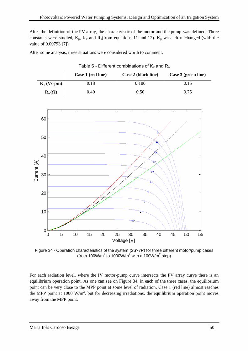
Photovoltaic Powered Water Pumping Systems: Design and Optimization of an Irrigation System
Maria Inês Cardoso Bexiga 50
After the definition of the PV array, the characteristic of the motor and the pump was defined. Three
constants were studied, Kp, Kv and Ra(from equations 11 and 12). Kp was left unchanged (with the
value of 0.00793 [7]).
After some analysis, three situations were considered worth to comment.
Table 5 - Different combinations of Kv and Ra
Case 1 (red line) Case 2 (black line) Case 3 (green line)
Kv (V/rpm) 0.18 0.180 0.15
Ra (Ω) 0.40 0.50 0.75
Figure 34 - Operation characteristics of the system (2S×7P) for three different motor/pump cases
(from 100W/m2 to 1000W/m
2 with a 100W/m
2 step)
For each radiation level, where the IV motor-pump curve intersects the PV array curve there is an
equilibrium operation point. As one can see on Figure 34, in each of the three cases, the equilibrium
point can be very close to the MPP point at some level of radiation. Case 1 (red line) almost reaches
the MPP point at 1000 W/m2, but for decreasing irradiations, the equilibrium operation point moves
away from the MPP point.
0 5 10 15 20 25 30 35 40 45 50 550
10
20
30
40
50
60
Voltage [V]
Curr
ent
[A]
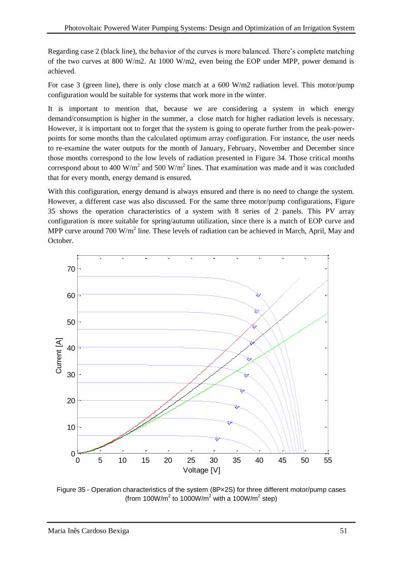
Photovoltaic Powered Water Pumping Systems: Design and Optimization of an Irrigation System
Maria Inês Cardoso Bexiga 51
Regarding case 2 (black line), the behavior of the curves is more balanced. There’s complete matching
of the two curves at 800 W/m2. At 1000 W/m2, even being the EOP under MPP, power demand is
achieved.
For case 3 (green line), there is only close match at a 600 W/m2 radiation level. This motor/pump
configuration would be suitable for systems that work more in the winter.
It is important to mention that, because we are considering a system in which energy
demand/consumption is higher in the summer, a close match for higher radiation levels is necessary.
However, it is important not to forget that the system is going to operate further from the peak-power-
points for some months than the calculated optimum array configuration. For instance, the user needs
to re-examine the water outputs for the month of January, February, November and December since
those months correspond to the low levels of radiation presented in Figure 34. Those critical months
correspond about to 400 W/m2 and 500 W/m
2 lines. That examination was made and it was concluded
that for every month, energy demand is ensured.
With this configuration, energy demand is always ensured and there is no need to change the system.
However, a different case was also discussed. For the same three motor/pump configurations, Figure
35 shows the operation characteristics of a system with 8 series of 2 panels. This PV array
configuration is more suitable for spring/autumn utilization, since there is a match of EOP curve and
MPP curve around 700 W/m2 line. These levels of radiation can be achieved in March, April, May and
October.
Figure 35 - Operation characteristics of the system (8P×2S) for three different motor/pump cases
(from 100W/m2 to 1000W/m
2 with a 100W/m
2 step)
0 5 10 15 20 25 30 35 40 45 50 550
10
20
30
40
50
60
70
Voltage [V]
Curr
ent
[A]
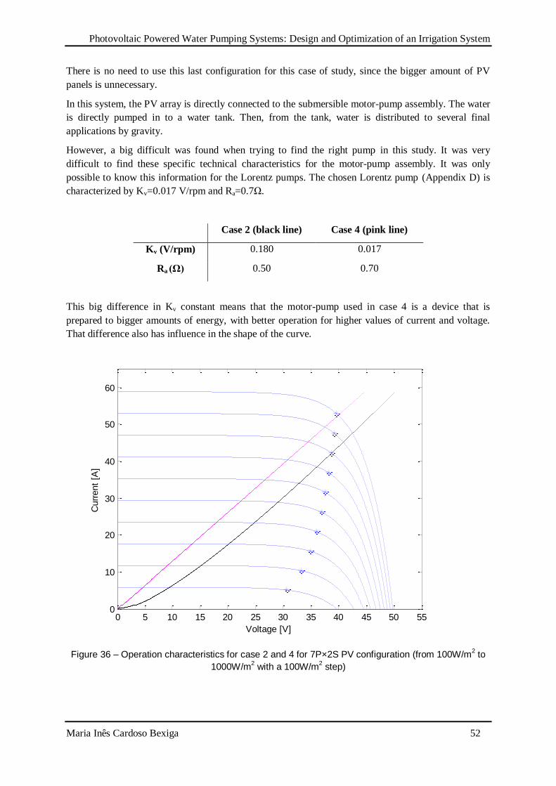
Photovoltaic Powered Water Pumping Systems: Design and Optimization of an Irrigation System
Maria Inês Cardoso Bexiga 52
There is no need to use this last configuration for this case of study, since the bigger amount of PV
panels is unnecessary.
In this system, the PV array is directly connected to the submersible motor-pump assembly. The water
is directly pumped in to a water tank. Then, from the tank, water is distributed to several final
applications by gravity.
However, a big difficult was found when trying to find the right pump in this study. It was very
difficult to find these specific technical characteristics for the motor-pump assembly. It was only
possible to know this information for the Lorentz pumps. The chosen Lorentz pump (Appendix D) is
characterized by Kv=0.017 V/rpm and Ra=0.7Ω.
Case 2 (black line) Case 4 (pink line)
Kv (V/rpm) 0.180 0.017
Ra (Ω) 0.50 0.70
This big difference in Kv constant means that the motor-pump used in case 4 is a device that is
prepared to bigger amounts of energy, with better operation for higher values of current and voltage.
That difference also has influence in the shape of the curve.
Figure 36 – Operation characteristics for case 2 and 4 for 7P×2S PV configuration (from 100W/m2 to
1000W/m2 with a 100W/m
2 step)
0 5 10 15 20 25 30 35 40 45 50 550
10
20
30
40
50
60
Voltage [V]
Curr
ent
[A]
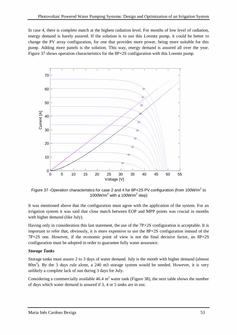
Photovoltaic Powered Water Pumping Systems: Design and Optimization of an Irrigation System
Maria Inês Cardoso Bexiga 53
In case 4, there is complete match at the highest radiation level. For months of low level of radiation,
energy demand is barely assured. If the solution is to use this Lorentz pump, it could be better to
change the PV array configuration, for one that provides more power, being more suitable for this
pump. Adding more panels is the solution. This way, energy demand is assured all over the year.
Figure 37 shows operation characteristics for the 8P×2S configuration with this Lorentz pump.
Figure 37 -Operation characteristics for case 2 and 4 for 8P×2S PV configuration (from 100W/m2 to
1000W/m2 with a 100W/m
2 step)
It was mentioned above that the configuration must agree with the application of the system. For an
irrigation system it was said that close match between EOP and MPP points was crucial in months
with higher demand (like July).
Having only in consideration this last statement, the use of the 7P×2S configuration is acceptable. It is
important to refer that, obviously, it is more expensive to use the 8P×2S configuration instead of the
7P×2S one. However, if the economic point of view is not the final decisive factor, an 8P×2S
configuration must be adopted in order to guarantee fully water assurance.
Storage Tanks
Storage tanks must assure 2 to 3 days of water demand. July is the month with higher demand (almost
80m3). By the 3 days rule alone, a 240 m3 storage system would be needed. However, it is very
unlikely a complete lack of sun during 3 days for July.
Considering a commercially available 46.4 m3 water tank (Figure 38), the next table shows the number
of days which water demand is assured if 3, 4 or 5 tanks are in use.
0 5 10 15 20 25 30 35 40 45 50 550
10
20
30
40
50
60
70
Voltage [V]
Curr
ent
[A]
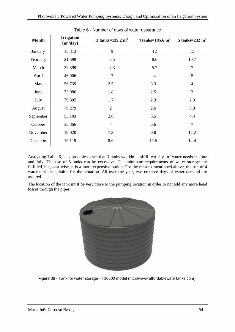
Photovoltaic Powered Water Pumping Systems: Design and Optimization of an Irrigation System
Maria Inês Cardoso Bexiga 54
Table 6 - Number of days of water assurance
Month Irrigation
(m3/day)
3 tanks=139.2 m3 4 tanks=185.6 m
3 5 tanks=232 m
3
January 15.313 9 12 15
February 21.599 6.5 8.6 10.7
March 32.399 4.3 5.7 7
April 46.906 3 4 5
May 56.739 2.5 3.3 4
June 73.986 1.8 2.5 3
July 79.305 1.7 2.3 2.9
August 70.279 2 2.6 3.3
September 53.193 2.6 3.5 4.4
October 33.366 4 5.6 7
November 19.020 7.3 9.8 12.2
December 16.119 8.6 11.5 14.4
Analyzing Table 6, it is possible to see that 3 tanks wouldn’t fulfill two days of water needs in June
and July. The use of 5 tanks can be excessive. The minimum requirements of water storage are
fulfilled, but, cost wise, it is a more expensive option. For the reasons mentioned above, the use of 4 water tanks is suitable for the situation. All over the year, two or three days of water demand are
assured.
The location of the tank must be very close to the pumping location in order to not add any more head
losses through the pipes.
Figure 38 - Tank for water storage - T10500 model (http://www.affordablewatertanks.com)
Photovoltaic Powered Water Pumping Systems: Design and Optimization of an Irrigation System
Maria Inês Cardoso Bexiga 55
System’s final configuration
A review of the most important parameters of the system is shown in Table 7 .
Table 7 - System's final configuration
Total area 16119 m2
Total Dynamic Head 60 meters
Maximum daily water volume 79.305 m3
Ppeak 2.07 kW
Number of modules 16 modules (2S×8P)
Motor-Pump Centrifugal submersible Pump :
Kv=0.017V/rpm Ra=0.7Ω
Storage capacity 4 × 46.4 m3 water tanks = 185.6 m
3
Photovoltaic Powered Water Pumping Systems: Design and Optimization of an Irrigation System
Maria Inês Cardoso Bexiga 56
6. Conclusions
It is clear that the use of PV water-pumping systems (or pumping systems using other renewable
energy) are suitable for rural and remote areas, emphasizing the fact that such applications may
achieve social and economic development of the local population. It can solve both water irrigation
and domestic water consumption problems.
6.1. Case of study conclusions/Discussion
A methodology for design an SPWPSs was suggested. Several aspects were assessed, such as water
needs and correspondent electrical energy demand. The whole study was made just theoretically, with
estimated data and without any experimental data.
For a system which energy demand changes throughout the year, it is essential to do a monthly
evaluation of energy flows. In this case, sizing was made for the month with higher energy
demand/energy supply ratio, corresponding to a situation which the number of PV panels needed was
also higher. The configuration lead to an assurance of energy in every months.
The process of choosing the PV configuration and associated motor/pump is an iterative process. In
simultaneous, several PV configurations and motor/pumps were studied. In this thesis only two PV
array configurations were considered relevant to present. 7P×2S is better to a motor-pump device that
is more prepared to low power applications. 8P×2S is a possible solution to use the Lorentz model.
This shows, that without any use of a controller system, the number of PV panels is not the only
variable to assess.
This type of sizing can get very difficult, since manufacturer’s datasheets are very incomplete
regarding some parameters and specific information is not available. It becomes easier to select the
motor-pump assembly, just using parameters like maximum water rate and maximum total dynamic
head. However the several disadvantages of using an MPPT (more expensive, more complicated and
less reliable), can justify the use of this multistep sizing method for small systems, using the EOP and
MPP curves.
Storage is very important for off-grid systems. In an irrigation system, storage units would be, most
likely, in an outdoors space, leading to bigger chances of equipment damaging. In this case, water
tanks were found to be the simplest solution. They are cheaper, and easier to operate and maintain than
batteries.
For a most accurate sizing of a PV water-pumping system, an hydrodynamic simulation must be made.
This way it would be possible to evaluate pressure and head losses through the circuit. It would be also
usefull to see the behavior of the system when changes of flow happen.
6.2. The future of PV water-pumping systems
The future of PV water pumping is dependent on a number of factors, both technological and
sociological, and both of these must be considered by all involved parties. It is evident that a re-think
of the technology is required if sustainability is going to be a real option. The electronic systems in use
today can be very complex, they are unlikely to be cheap enough for simple replacement and are not
sufficiently reliable to match the lifetime of the pumping equipment. Because SPWPSs are suitable
mostly for rural areas, they must be projected in a way that everyone can use them. The options here
are therefore:
• a significant improvement in present designs;
Photovoltaic Powered Water Pumping Systems: Design and Optimization of an Irrigation System
Maria Inês Cardoso Bexiga 57
• a complete re-design of the control systems to become either maintainable - which is highly
unlikely - or extremely cheap and easy to replace; or
• to do away with a control system completely and employ direct connection between PV array and
pump motor.
While the last case seems to be the most appropriate, it also implies reconsideration of the motor-
pump unit. The only present pump/motor combination that could be directly connected with any
realistic degree of power tracking is the centrifugal pump with brushed permanent magnet motor. This
pump is site-specific and, at higher output heads, must be a sophisticated multi-stage device. The extra
expense involved in designing the pump for a particular site and paying for a site-visit by a trained
engineer makes the option highly unattractive. This leaves positive-displacement pumps with non-
ideal I-V characteristics. The choices here, therefore, seem to be:
• accepting a loss of output from a positive-displacement pump in return for lower costs and more
wide-ranging applicability;
• returning to using an MPPT system; or
• a complete re-design of the pump.
If this latter option is employed, it leaves the way open to consider entirely new types of pump and
drive mechanisms that are low cost, reliable, and efficient. This is indeed the option currently under
investigation at the University of Durham where a new linear drive is being developed for use in PV
modules. The pump is based on an electromagnet driving a linear actuator, which also acts as the
driving piston, and promises performance across a wide range of output heads and flow rates.
The issues that must be addressed, however, are more than technical and go beyond simple village
level operation and maintenance characteristics. They are highly involved and are connected with
social issues, but experience shows that they are not unsolvable and that the overall design solution
can have a number of potential benefits, ranging from increased physical and mental health to
improved education and social cohesion. Thousands of pumps that continue to operate are evidence
that SPWPSs can play their part in providing a sustainable solution to the problem of water provision
in developing countries. What is needed is an unrelenting effort to learn and to understand the lessons
that these and other, non SPWPSs projects have shown, to generate consumer-led demand and to react
by supplying pumps that can be considered to be Appropriate Technology.
Photovoltaic Powered Water Pumping Systems: Design and Optimization of an Irrigation System
Maria Inês Cardoso Bexiga 58
References[1] M. C. Fedrizzi, “Fornecimento de água com sistemas de
bombeamento fotovoltaicos,” 1997.
[2] M. Çapik, A. Yilmaz Osman, and Í. Çavusoglu, “Present situation and
potencial role of renewable energy in Turkey,” Renew. Energy, vol. 46, pp.
1–13, 2012.
[3] C. Gopal, M. Mohanraj, P. Chandramohan, and P. Chandrasekar,
“Renewable energy source water pumping systems—A literature review,”
Renew. Sustain. Energy Rev., vol. 25, pp. 351–370, Sep. 2013.
[4] J. Ramos, “Water Supply Systems Efficiency - Application of Renewable
Energy Sources,” 2007.
[5] J. K. Kaldellis, E. Meidanis, and D. Zafirakis, “Experimental energy
analysis of a stand-alone photovoltaic-based water pumping installation,”
Appl. Energy, vol. 88, pp. 4556–4562, 2011.
[6] M. Thomas, “Water Pumping: The Solar Alternative,” Albuquerque, New
Mexico, 1995.
[7] Z. A. Firatoglu and B. Yesilata, “New approaches on the optimization of
directly coupled PV pumping systems,” Sol. Energy, vol. 77, no. 1, pp. 81–
93, Jan. 2004.
[8] “Practical Action - technology challenging poverty | Practical Action.”
[Online]. Available: http://practicalaction.org/. [Accessed: 05-May-2014].
[9] a. K. M. Sadrul Islam, M. a. H. Mondal, and M. Ahiduzzaman, “A Case
Study of Grid Connected Solar PV Irrigation System in Semi-Arid Region
of Bangladesh,” Int. J. Sustain. Water Environ. Syst., vol. 1, no. 1, pp. 33–
38, Sep. 2010.
[10] R. B. Roy, “Design and Performance Analysis of the Solar PV DC Water
Pumping System,” Can. J. Electr. Electron. Eng., vol. 3, no. 7, pp. 403–
412, 2012.
[11] P. C. Pande, a. K. Singh, S. Ansari, S. K. Vyas, and B. K. Dave, “Design
development and testing of a solar PV pump based drip system for
orchards,” Renew. Energy, vol. 28, no. 3, pp. 385–396, Mar. 2003.
[12] A. Bhave, “Potential for solar water-pumping systems in India,” Appl.
Energy, vol. 48, pp. 197–200, 1994.
Photovoltaic Powered Water Pumping Systems: Design and Optimization of an Irrigation System
Maria Inês Cardoso Bexiga 59
[13] E. Mahmoud, “Renewable energy and sustainable developments in Egypt :
photovoltaic water pumping in remote areas,” vol. 74, pp. 141–147, 2003.
[14] L. Qoaider and D. Steinbrecht, “Photovoltaic systems: a cost competitive
option to supply energy to off-grid agriculture communities in arid
regions,” Appl. Energy, vol. 87, pp. 427–35, 2010.
[15] Y. Yu, J. Liu, H. Wang, and M. Liu, “Assess the potential os solar
irrigation systems for sustaining pasture lands in arid regions - a case study
in Northwest China,” Appl. Energy, vol. 88, pp. 3176–82, 2011.
[16] A. Mokeddem, A. Midoun, D. Kadri, S. Hiadsi, and I. a. Raja,
“Performance of a directly-coupled PV water pumping system,” Energy
Convers. Manag., vol. 52, no. 10, pp. 3089–3095, Sep. 2011.
[17] A. Hamidat, B. Benyoucef, and T. Hartani, “Small-scale irrigation with
photovoltaic water pumping system in Sahara regions,” Energy Convers.
Manag., vol. 28, pp. 1081–96, 2003.
[18] A. Boutelhig, Y. Bakelli, I. Hadj Mahammed, and A. Hadj Arab,
“Performances study of different PV powered DC pump configurations for
an optimum energy rating at different heads under the outdoor conditions
of a desert area,” Energy, vol. 39, no. 1, pp. 33–39, Mar. 2012.
[19] N. Hamrouni, M. Jraidi, and A. Chérif, “Theoretical and experimental
analysis of the behaviour of a photovoltaic pumping system,” Sol. Energy,
vol. 83, no. 8, pp. 1335–1344, Aug. 2009.
[20] K. Meah, S. Fletcher, and S. Ula, “Solar photovoltaic water pumping for
remote locations,” Renew. Sustain. Energy Rev., vol. 12, pp. 472–87, 2008.
[21] K. Meah, S. Ula, and S. Barrett, “Solar photovoltaic water pumping—
opportunities and challenges,” Renew. Sustain. Energy Rev., vol. 12, no. 4,
pp. 1162–1175, May 2008.
[22] T. Chandratilleke and J. Ho, “A study of a photovoltaic array for water
pumping,” Sol. Wind Technol., vol. 3, pp. 59–71, 1986.
[23] V. Badescu, “Time dependent model of a complex PV water pumping
system,” Renew. Energy, vol. 28, no. 4, pp. 543–560, Apr. 2003.
[24] S. Sung and M. Mon, “Design and Performance Analysis of Solar Water
Pumping System,” Int. Conf. Environ. Prot. Renew. Energy, 2013.
Photovoltaic Powered Water Pumping Systems: Design and Optimization of an Irrigation System
Maria Inês Cardoso Bexiga 60
[25] T. Morales and J. Busch, “Design of Small Photovoltaic (PV) Solar-
Powered Water Pump Systems,” Portland, Oregon, 2010.
[26] T. D. Short and P. Thompson, “Breaking the mould : solar water pumping
— the challenges and the reality,” Sol. Energy, vol. 75, pp. 1–9, 2003.
[27] T. Jenkins, “Designing Solar Water Pumping Systems for Livestock,” New
Mex. State Univ., pp. 1–12.
[28] A. Da, E. D. E. Perda, and P. Diâmetro, “Relações água-solo-planta-
atmosfera,” no. 035, pp. 247–252, 1998.
[29] M. Abu-Aligah, “Design of Photovoltaic Water Pumping System and
Compare it with Diesel Powered Pump,” Jordan J. Mech. Ind. Eng., vol. 5,
pp. 273–280, 2011.
[30] M. Al-Smairan, “Application of photovoltaic array for pumping water as
an alternative to diesel engines in Jordan Badia, Tall Hassan Station: Case
Study,” Renew. Sustain. Energy Rev., vol. 16, pp. 4500–4507, 2012.
[31] “PVCDROM | PVEducation.” [Online]. Available:
http://pveducation.org/pvcdrom. [Accessed: 28-Aug-2014].
[32] E. Tawil, “Module 3 Pumps,” in Mechanical Science, 2010.
[33] J. E. Purcell and J. A. Silvaggio, “A comparison of positive displacement
and centrifugal pump applications.”
[34] a. Hamidat and B. Benyoucef, “Mathematic models of photovoltaic motor-
pump systems,” Renew. Energy, vol. 33, no. 5, pp. 933–942, May 2008.
[35] Blackmer, “Centrifugal Pumps vs. Positive Displacement Pumps,” 2012.
[Online]. Available:
http://www.blackmersmartenergy.com/comparativedata/centrifugal-
pumps-vs-positive-displacement-pumps.html.
[36] L. Zanirato, L. Moura, and T. Cordeiro, “Técnicas de bombeamento de
fluídos aplicando energia solar fotovoltaica,” 2011.
[37] S. J. Chapman, Electric Machinery Fundamentals. Mc Graw Hill, 2005.
[38] M. Mani and R. Pillai, “Impact of dust on solar photovoltaic (PV)
performance: research status, challenges and recommendations.,” Renew.
Sustain. Energy Rev., vol. 14, pp. 3124–31, 2010.
Photovoltaic Powered Water Pumping Systems: Design and Optimization of an Irrigation System
Maria Inês Cardoso Bexiga 61
[39] S. Mekhilef, R. Saidur, and M. Kamalisarvestani, “Effect of dust, humidity
and air velocity on efficiency of photovoltaic cells,” Renew. Sustain.
Energy Rev., vol. 16, pp. 2920–5, 2012.
[40] “JRC’s Institute for Energy and Transport - PVGIS - European
Commission.” [Online]. Available: http://re.jrc.ec.europa.eu/pvgis/.
[Accessed: 30-Jul-2014].
[41] J. Twidell and T. Weir, Renewable Energy Resources. 2006, pp. 85–114.
[42] A. E. Pascual, “Sizing of stand alone PV systems based on the ‘ worst
month ,’” no. ISF, 1998.
[43] A. Dev and S. B. Jeyaprabha, “Modeling and Simulation of Photovoltaic
Module in MATLAB,” no. figure 1, pp. 268–273, 2013.
[44] A. Luque and S. Hegedus, Handbook of Photovoltaic Science and
Engineering. Wiley, 2003.
[45] H. A. Toliyat and G. B. Kliman, Handbook of Electric Motors, Second
Edi. Dekker, 2004.
[46] A. Rosa, “Estimativa das necessidades hídricas das plantas de jardim,”
Ministério da Agric., pp. 1–27.
[47] T. D. Short and R. Oldach, “Solar Powered Water Pumps: The Past, the
Present—and the Future?,” J. Sol. Energy Eng., vol. 125, no. 1, p. 76,
2003.
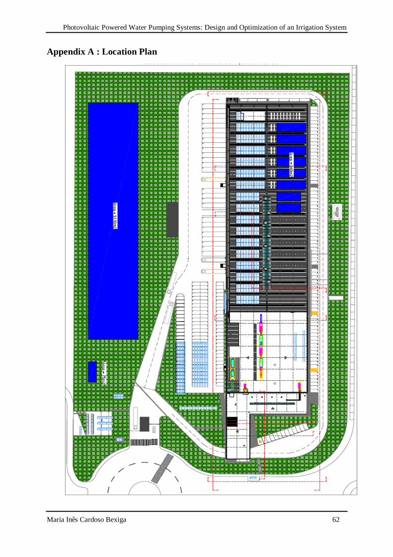
Photovoltaic Powered Water Pumping Systems: Design and Optimization of an Irrigation System
Maria Inês Cardoso Bexiga 62
Appendix A : Location Plan
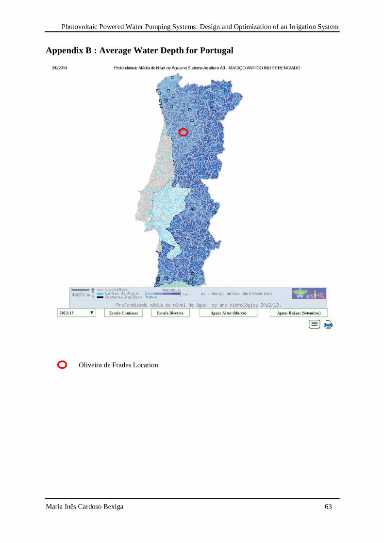
Photovoltaic Powered Water Pumping Systems: Design and Optimization of an Irrigation System
Maria Inês Cardoso Bexiga 63
Appendix B : Average Water Depth for Portugal
Oliveira de Frades Location

Photovoltaic Powered Water Pumping Systems: Design and Optimization of an Irrigation System
Maria Inês Cardoso Bexiga 64
Appendix C : Matlab File
clear all; close all; clc;
T=28+273; Tr1=40; Tr=(Tr1-32)+273; S=[100 90 80 70 60 50 40 30 20 10]; %mW/cm2 corresponde a 1000 800 etc W/m2 ki=0.00023; Iscr=8.39; Irr=0.000021; k=1.38*(10^-23); q=1.6*(10^-19); A=2.35; Eg0=1.166; alpha=0.473; beta=636; Eg=Eg0-(alpha*T*T)/(T+beta)*q; %energia do band gap do semi condutor Np=1*8; Ns=36*2; Ra=0.17; V=[0:0.005:23*Ns];
for i=1:10 Iph=(Iscr+ki*(T-Tr))*(S(i)/100); Irs=Irr*((T/Tr)^3)*exp(q*Eg/(k*A)*((1/Tr)-(1/T))); I=Np*Iph-Np*Irs*(exp(q/(k*T*A)*V./Ns)-1); P=V.*I; [x y]=max(P);
w=sqrt((1.8/0.00793).*I);% Vm=0.18*w+I.*0.50; % w2=sqrt((1.5/0.00793).*I); Vm2=0.15*w2+I.*0.75; w3=sqrt((1.8/0.00793).*I); Vm3=0.18*w3+I.*0.40; w4=sqrt((0.17/0.00793).*I); Vm4=0.017*w4+I.*0.70;
figure(1) plot(V,I) axis([0 55 0 75]) xlabel('Voltage [V]') ylabel('Current [A]') hold on
plot(Vm,I,'k') plot(Vm2,I,'g') plot(Vm3,I,'r') plot(Vm4,I,'m')
Ip=I(y); Vp=V(y); plot(Vp,Ip,'*') hold on end
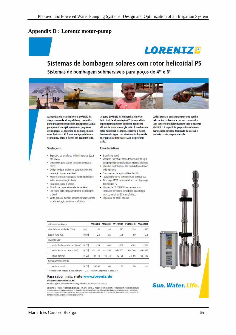
Photovoltaic Powered Water Pumping Systems: Design and Optimization of an Irrigation System
Maria Inês Cardoso Bexiga 65
Appendix D : Lorentz motor-pump
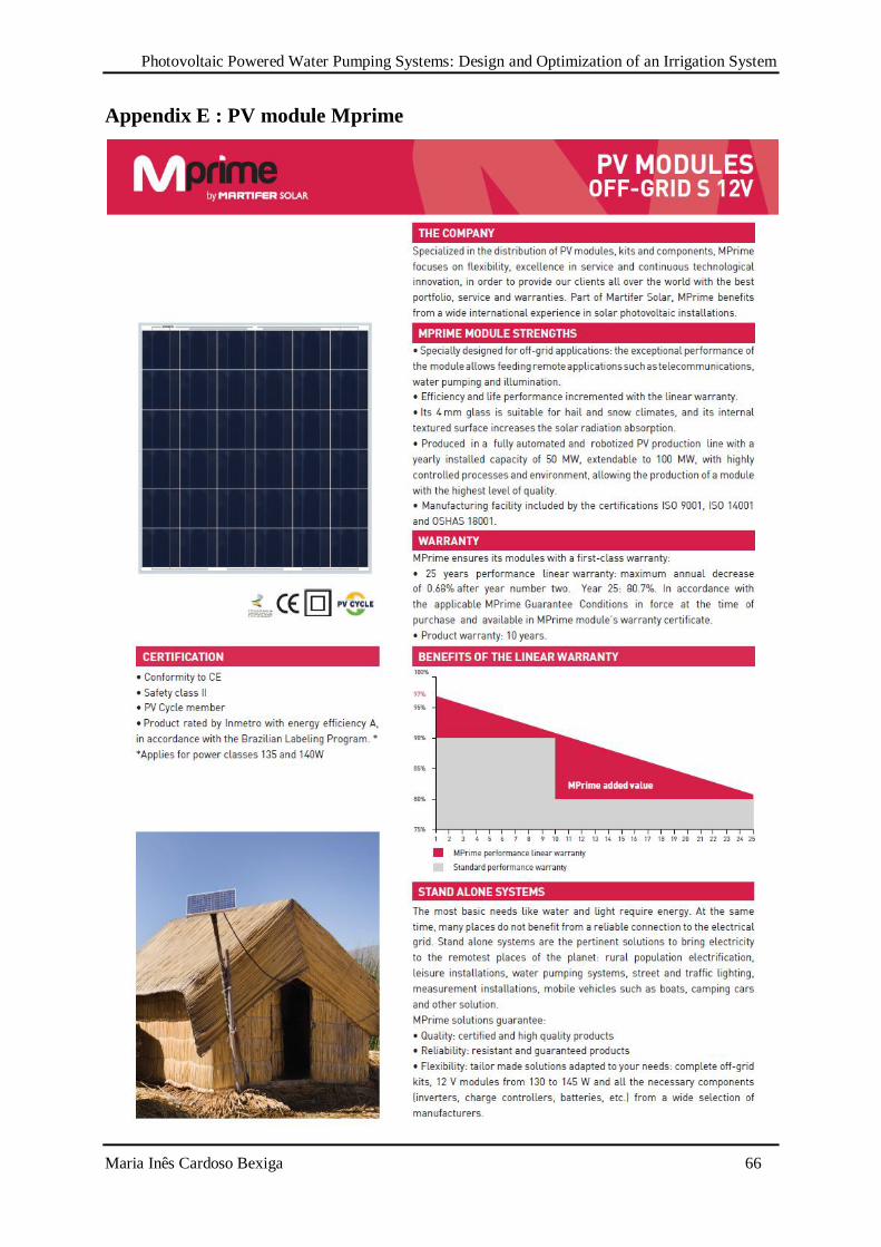
Photovoltaic Powered Water Pumping Systems: Design and Optimization of an Irrigation System
Maria Inês Cardoso Bexiga 66
Appendix E : PV module Mprime
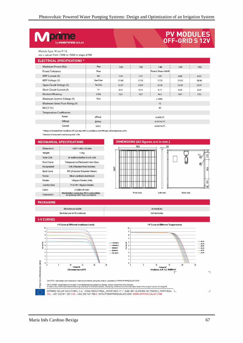
Photovoltaic Powered Water Pumping Systems: Design and Optimization of an Irrigation System
Maria Inês Cardoso Bexiga 67