photovoltaics - asetyc€¦ · system lc4® • with integrated locking • alternatively to be...
TRANSCRIPT

Connectivity Solutions LC4®
Photovoltaics

System LC4®
• with integrated locking• alternatively to be unlocked either manually or only with a
tool, according to NEC 2008 NFPA 70• connectors, cables and junction boxes
• industrially pre-assembled, overmolded and tested• field-attachable versions also available
Sola
r-Fa
bri
k A
G
Pho
enix
So
lar
AG
Lumberg Connect GmbH:LC4-AM 00 / LC-4-AM 01
9/2011
good
www.photon.info
Lumberg Connect GmbH:LC4-CP 30 / LC4-CP 31
9/2011
good
www.photon.info
www.lumberg.com 01/2014

USA
Singapore
PolandCzechia
Germany
China
Succeed together
production and service
service
www.lumberg.com 01/2014

Connectors
• standard cables• cables according to specific markets’ needs, i.e. for
America, Europe, Asia, or multistandard
Cables
System LC4®
• with integrated locking• alternatively to be unlocked
manually or acc. to NEC 2008 NFPA 70, only with a tool
2.5 mm²AWG 14
4.0 mm²AWG 12
6.0 mm²AWG 10
with spring clamps
Junction boxes for thin film modules
Junction boxes for crystalline modules
einpolige Anschlussdosen,für durch die Modul rück -wand geführte Bändchen
zweipolige Anschlussdosen,für durch die Modul rück -wand geführte Bändchen,optional mit Diode
www.lumberg.com 01/2014

Solutions for module producers
juwi solar GmbH
customized solutions®customized solutions®Lumberg Connect
Module junction technolgoy
Features
• special direct contacting inside the junction boxes,• very flat junction box designs• for crystalline or thinfilm modules• single-pole and two-pole versions• with self-adhesive pad or for gluing• sealing by means of potting• with LC4® connectors with integrated locking• overmolded connectors: outstanding environmental seals,
excellent strain relief, unsurpassed ruggedness and dura-bility
Benefits
• fast, easy to automate and secure connecting processesinside the junction boxes
• minimized contact resistance• minimized cable lengths with single-pole junction boxes• contracted dimensions of the junction boxes allow for
high packaging density of the modules• permanently reliable system operation• minimized attendance and servicing expenditure• the best solution available for each module type• all from one source, available worldwide• system meets international requirements, including
NEC 2008 NFPA 70• customized solutions at any time
Inve
ntu
x Te
chn
olo
gie
s A
GSo
lar-
Fab
rik
AG
www.lumberg.com 01/2014

Datakom-Steckverbinder
Internal wiring
Detailed information about these connector systems can befound in additional Lumberg catalogs and on the Internet.
• screw terminal blocks• connectors with insulation displacement technology (IDT)• connectors with screw clamp technology• connectors with crimp technology
• indirect, two-part connectors• direct connectors for the circuit board edge• for discrete stranded wires or flat cables• pitches from 1.27 mm (.050") up to 10.0 mm (.394")• for load currents up to 15 A/630 V AC
• I/O interfaces including RJ45 and USB• circular connectors up to IP 68
For the internal wiring ofthe components, Lumbergoffers a wide range of solu-tions, all from one source.
for• inverters• power optimizers• auxiliary components
Compact Catalog Connector Systems
protective caps
Interface from outside
manual crimp tools cables: standard or customized
2.5 mm²AWG 14
4.0 mm²AWG 12
6.0 mm²AWG 10
crimp machines forcost-effective produc-tion of higher volumes
Receptacles of system LC4®
• with integrated locking• alternatively to be unlocked manually or only with a tool,
acc. to NEC 2008 NFPA 70
www.lumberg.com 01/2014

customized solutions®customized solutions®Lumberg Connect
Features
• photovoltaic receptacles as the interface• highest protection degree IP 68• rugged and durable• LC4® system with integrated locking• protective caps for transport and spare receptacles
• connector systems and terminal blocks for the internalwiring
• proven a billionfold in various industries
Benefits
• permanently reliable systemoperation
• fast and easy to assemble
• proven connector systems from one source:into the housing and within the housing
• many systems designed for automated processing• available worldwide• customized solutions
From the field into the housing – and within...
Solutions for inverter and component producers
www.lumberg.com 01/2014

cables: standard or customized crimp tool: only one tool forall wire sections
Components and auxiliaries for on-site assembly
Wiring of solar power plants:industrially pre-assembled, overmolded, tested
Pho
enix
So
lar
AG
Components and auxiliaries for on-site assembly
Photovoltaic array harnesses LC4®
• ready-to-plug: industrially pre-assembled• industrially tested• with LC4® connectors• with integrated locking, alternatively to
be unlocked manually or only with a tool, acc. toNEC 2008 NFPA 70
2.5 mm²AWG 14
4.0 mm²AWG 12
6.0 mm²AWG 10
In-line fusesIn-line diodes
Field-attachable connectors from system LC4®
• with integrated locking• alternatively to be unlocked
manually or only with a tool, acc. to NEC 2008 NFPA 70
www.lumberg.com 01/2014

Solutions for installers and system integrators
customized solutions®customized solutions®Lumberg Connect
Wire fast
Some of the world’s largestsolar power plants are wiredwith Lumberg components.These plants (right) combine700,000 resp. 550,000 thin-film modules.
Features
• photovoltaic array harnesses: everything is pre-assembledand ready-to-plug
• harnesses 100 % tested• overmolded connectors: outstanding environmental seals,
excellent strain relief, unsurpassed ruggedness and dura-bility
• extremely sturdy: overmolded connector often evenstronger than the cable
• with LC4® connectors with integrated locking• highest protection degree IP 68• halogen-free• UV and ozone-resistant
Benefits
• up to 30 % shorter installation time• permanently reliable system operation• minimized attendance and servicing expenditure• no lengthy crimping on-site when using pre-assembled
and overmolded harnesses• ideal wiring strategy for every application:
overmolded solution is pre-assembled and tested, field-attachable solution available for home run cables
• system meets international requirements, including NEC 2008 NFPA 70
• all from one source, available worldwide• standard and customized solutions
Wire faster and more effectively
juw
i so
lar
Gm
bH
Inve
ntu
x Te
chn
olo
gie
s A
G
PVStrom GmbH & Co. KG Solarpark Rodenäs GmbHPhoenix Solar AG
www.lumberg.com 01/2014

page 12
page 14
page 18
page 21
page 18
page 25
Junction boxes LC4® for crystalline modules
LC4-JC JC = Junction boxes for Crystallinemodules
Junction boxes LC4® for thinfilm modules, single-pole andtwo-pole
LC4-JT JT = Junction boxes for Thinfilmmodules
Connecting cables LC4®, with connector at one end
LC4-AM AM = Cable Assemblies, Modularharnesses
Connecting cables LC4®, with connectors at both ends
LC4-AM AM = Cable Assemblies, Modularharnesses)
Array harnesses LC4®, pre-assembled according tocustom er’s specification
LC4-AT AT = Cable Assemblies, T-typearray harnesses
Connectors LC4®, field-attachable, with crimp contacts
LC4-CP CP = Connector Parts
www.lumberg.com 01/2014

In-line fuses LC4®
In-line diodes LC4®
LC4-CP CP = Connector Parts
Chassis receptacles LC4®, for front mounting, with crimpcontacts
Connectivity solutions for photovoltaic power systemsOverview system LC4®
Branch connectors LC4®
page 29
page 27
page 31
page 37
Unlocking tool LC4®
Processing tools and machines LC4®
LC4-CP CP = Connector Parts
LC4-CX CX = Connector auXiliaries
Features• LC4® with integrated locking according to NEC 2008
NFPA 70• highest protection degree IP 68• halogen-free, UV and ozone-resistant• two options: pre-assembled, overmolded and tested or
field-attachable• standard product range and customized solutions
Benefits• permanently reliable system operation• minimized attendance and servicing expenditure• no lengthy crimping on-site when using pre-assembled
and overmolded harnesses• ideal wiring strategy for every application:
overmolded solution is industrially pre-assembled andtested, field-attachable solution available complimentarily
• system meets international requirements, including NEC 2008 NFPA 70
LC4-CP CP = Connector Parts
Protective caps LC4®
LC4-CX CX = Connector auXiliaries
page 37
www.lumberg.com 01/2014

Connectivity solutions for photovoltaic power systems LC4®-JC – Junction boxes for Crystalline modules
Crystalline modules:Wiring diagram
Two-pole junction boxes,for ribbons fed through theback plane of the module
LC4-JC details upon requestDesignation
Photovoltaic junction box for crystalline modules1, withcon necting cables and LC4® connectors, with 2–4 springclamps and 0–3 diodes, for ribbons fed through the backplane of the module, mounting with self-adhesive pad2 orby means of glue
1. Temperature range -40 °C/+85 °C (IEC)-40 °C/+90 °C (UL)(+125 °C upper limit temperature)
2. Materials halogen-free, UV-resistant
Housing/cover m-PPE, 5VA according to UL 94Contact CuNiSi, tin-platedPressure contact spring CrNiCap nut m-PC, V0 according to UL 94Sealings siliconePressure compensation seal PTFEAdhesive pad upon request
3. Mechanical data
Mating with photovoltaic connectors LC4Further data see LC4-CP 3.../LC4-AMProtection degree (junction box)3 IP 65Connectable contact ribbonsWidth ≤ 10.0 mmThickness ≤ 0.1 mmOther dimensions upon requestConnected conductorPhotovoltaic cable, double-insulated, technical Data upon requestSection alternatively 2.5 mm2 (AWG 14), TÜV-approved
4.0 mm2 (AWG 12), TÜV/UL-approved6.0 mm2 (AWG 10), TÜV/UL-approved
4. Electrical data (at Tamb 20 °C)
Contact resistance ≤ 1 mΩ
Rated current (IEC) various diodes available, value de-pending on type of diode and diodebypass test, details upon request
Rated current (UL) 15 A DC (AWG 14)20 A DC (AWG 12, AWG 10)without diode, details upon request
Rated voltage4 1000 V DC (IEC)/600 V DC (UL)Modul working voltage 100 V DCOvervoltage category4 III (8 kV)Material group4 IIIa (IEC)/2 (UL) (CTI ≥ 250)Creepage distance/clearance between
all other live parts 12.7 mm/9.5 mmlive parts and touchable surfaces 20.0 mm
Pollution degree4 3Protective class IIInsulation resistance > 10 GΩ
1 according to application class A of IEC 61730-1/UL 17032 appropriate materials upon request3 according to IEC 60529/DIN EN 605294 according to DIN EN 60664/IEC 60664 resp. according to ANSI/UL 746A
LC4-JC
*a self-adhesive pad option*b spacer option for fixation by means of glue*c assembly hole for contact ribbons, view without cover*d connecting cables: section 4.0 mm² (AWG 12) or 6.0 mm² (AWG 10)*e connecting cables: section 4.0 mm² (AWG 12) or 6.0 mm² (AWG 10)*f left connector: LC4-CP 3... or LC4-AM*g right connector: LC4-CP 3... or LC4-AM
®
www.lumberg.com 01/2014

Thinfilm modules:Wiring diagram
Single pole junction boxes, for ribbons fed through the back plane of the module
Designation
*a option with self-adhesive pad
*b spacer option for fixation by means of glue
*c potting hole
*d deaerator hole
*e connecting cables: section 2.5 mm² (AWG 14) or 4.0 mm² (AWG 12)
*f left connector: LC4-CP 3... or LC4-AM
*g right connector: LC4-CP 3... or LC4-AM
*h schematic diagram of bottom side with ribbon feed-through
*i opening of bottom side for ribbon feed-through
*j direction of cable departure
*k outline contour of junction box
Photovoltaic junction boxes for thin film modules1, single-pole with connecting cables and LC4® connectors, for rib-bons fed through the back plane of the module, mountingwith self-adhesive pad or by means of glue2, for potting2,cover for automatic assembly
1. Temperature range -40 °C/+85 °C (IEC)-40 °C/+90 °C (UL)(+155 °C upper limit temperature)
2. Materials UV-resistant
Housing/cover m-PET GF, 5VA according to UL 94Contact XCrNi, tin-platedCrimp bushing Cu, tin-platedAdhesive pad upon request
3. Mechanical data
Mating with photovoltaic connectors LC4Further data see LC4-CP 3.../LC4-AMProtection degree (junction box)3 IP 65Connectable contact ribbonsWidth ≤ 6.0 mmThickness ≤ 0.1 mmOther dimensions upon requestConnected conductorPhotovoltaic cable, double-insulated, technical Data upon requestSection alternatively 2.5 mm2 (AWG 14) or
4.0 mm2 (AWG 12)
4. Electrical data (at Tamb 20 °C)
Contact resistance ≤ 1.5 mΩ
Rated current 10 A at Tamb 85 °CRated voltage4 1000 V DC (IEC)/600 V DC (UL)Modul working voltage 100 V DCOvervoltage category4 III (8 kV)Material group4 IIIa (IEC)/2 (UL) (CTI ≥ 250)Creepage distance/clearance between
live parts and touchable surfaces 21.8 mmPollution degree4 3Protective class IIInsulation resistance > 10 GΩ
1 according to application class A of IEC 61730-1/UL 17032 appropriate materials upon request3 according to IEC 60529/DIN EN 605294 according to DIN EN 60664/IEC 60664 resp. according to ANSI/UL 746A
LC4-JT
Connectivity solutions for photovoltaic power systems LC4®-JT – Junction boxes for Thinfilm modules
LC4-JT details upon request
*e dimensionsØ (mm2) A (mm) B (mm)
2.5 54.4 17.754.0 56.4 18.75
®
www.lumberg.com 01/2014

*l *l
*l
Connectivity solutions for photovoltaic power systems LC4®-JT – Junction boxes for Thinfilm modules
Photovoltaic junction boxes for thin film modules1, two-pole, with connecting cables and LC4® connectors, with orwithout diode, for ribbons fed through the back plane ofthe module, mounting with self-adhesive pad or by meansof glue2, for potting2, cover for automatic assembly
1. Temperature range -40 °C/+85 °C (IEC)-40 °C/+90 °C (UL)(+155 °C upper limit temperature)
2. Materials UV-resistant
Housing/cover m-PET GF, 5VA according to UL 94Contact XCrNi, tin-platedCrimp bushing Cu, tin-platedAdhesive pad upon request
3. Mechanical data
Mating with photovoltaik connectors LC4Further data see LC4-CP 3.../LC4-AMProtection degree (junction box)3 IP 65Connectable contact ribbonsWidth ≤ 12.0 mmThickness ≤ 0.1 mmOther dimensions upon requestConnected conductorPhotovoltaic cable, double-insulated, technical Data upon requestSection alternatively 2.5 mm2 (AWG 14) or
4.0 mm2 (AWG 12)
4. Electrical data (at Tamb 20 °C)
Contact resistance ≤ 1.5 mΩ
Rated current (IEC) various diodes available, value de-pending on type of diode and diodebypass test, details upon request
Rated current (UL) 10 A DCwithout diode, details upon request
Rated voltage4 1000 V DC (IEC)/600 V DC (UL)Modul working voltage 100 V DCOvervoltage category4 III (8 kV)Material group4 IIIa (IEC)/2 (UL) (CTI ≥ 250)Creepage distance/clearance between
all other live parts 16.5 mmlive parts and touchable surfaces 21.8 mm
Pollution degree4 3Protective class IIInsulation resistance > 10 GΩ
1 according to application class A of IEC 61730-1/UL 17032 appropriate materials upon request3 according to IEC 60529/DIN EN 605294 according to DIN EN 60664/IEC 60664 resp. according to ANSI/UL 746A
*a option with self-adhesive pad*b spacer option for fixation by means of glue*c potting holes*d deaerator holes*e connecting cables: section 2.5 mm² (AWG 14) oder 4.0 mm² (AWG 12)*f left connector: LC4-CP 3... or LC4-AM*g right connector: LC4-CP 3... or LC4-AM*h schematic diagram of bottom side with ribbon feed-through*i opening of bottom side for ribbon feed-through*j direction of cable departure*k outline contour of junction box*l optional extra strain relief clip
Thinfilm modules:Wiring diagram
Two-pole junction boxes,for ribbons fed through theback plane of the module
Designation
LC4-JT
LC4-JT details upon request
®
www.lumberg.com 01/2014

X
X LC4-AM 00 IT
LC4-AM 00 LC4-AM 01
LC4-AM 62
Connectivity solutions for photovoltaic power systemsLC4®-AM – Cable Assemblies, Modular harnesses
LC4-AM 00LC4-AM 01
*a marking + on LC4-AM ...-1marking – on LC4-AM ...-2
LC4-AM 6...
LC4® photovoltaic connecting cables, with overmoldedconnectors, integrated locking and bend protectionLC4-AM 00: with plug and open endLC4-AM 01: with socket and open endLC4-AM 60: with two plugsLC4-AM 61: with two socketsLC4-AM 62: with plug and socket
1. Temperature range -40 °C/+85 °C (IEC)-40 °C/+90 °C (UL)(+125 °C upper limit temperature)
2. Materials halogen-free, UV-resistant
Insulating body m-PC, V1 according to UL 94Contact pin/bush CuNiSi, tin-platedSealing (sockets only) silicone
3. Mechanical data
Insertion force1 ≤ 20 NWithdrawal force1 ≥ 10 NRetaining force of locking latches2 ≥ 90 NMating cycles2 50Mating with photovoltaic connectors LC4Protection degree3 IP 68Connected conductorPhotovoltaic cable, double-insulated, technical data on requestSection alternatively 2.5 mm2 (AWG 14)
4.0 mm2 (AWG 12)6.0 mm2 (AWG 10)
4. Electrical data (at Tamb 20 °C)
Contact resistance2 ≤ 1 mΩ
Rated current (IEC)2 22 A at Tamb 85 °C, 2.5 mm2 (AWG 14)30 A at Tamb 85 °C, 4.0 mm2 (AWG 12)30 A at Tamb 85 °C, 6.0 mm2 (AWG 10)
Rated current (UL)2 35 A at Tamb 20 °C, 2,5/4,0/6,0 mm2
Rated voltage4 1000 V DC (IEC)/600 V DC (UL)Overvoltage category4 III (8 kV)Material group4 IIIa (IEC)/3 (UL) (CTI ≥ 225)Creepage distance/clearance between
contact and touchable surfaces 24.6 mmcontact and cable outlet 35.8 mm
Insulation resistance > 10 GΩ
1 measured with a polished steel gauge, nominal thickness 4.0 mm2 measured with a proper counterpart3 according to IEC 60529/DIN EN 60529
only in mated condition with a proper counterpartIP X8 requirements under agreement between manufacturer and user
4 according to DIN EN 60664/IEC 60664 resp. according to ANSI/UL 746A
Designation
LC4-AM ... details upon request
®
www.lumberg.com 01/2014

X
X LC4-AM 30 IT
LC4-AM 30LC4-AM 31
*a marking + on LC4-AM ...-1marking – on LC4-AM ...-2
LC4-AM 30 LC4-AM 31
LC4® photovoltaic connecting cables, with assembled con-nectors and integrated lockingLC4-AM 30: with plug and open endLC4-AM 31: with socket and open end
1. Temperature range -40 °C/+85 °C (IEC)-40 °C/+90 °C (UL)(+115 °C upper limit temperature)
2. Materials halogen-free, UV-resistantInsulating body m-PC, V1 according to UL 94Contact pin/bush CuNiSi, tin-platedSealing (sockets only) silicone
3. Mechanical dataInsertion force1 ≤ 20 NWithdrawal force1 ≥ 10 NRetaining force of locking latches2 ≥ 90 NMating cycles2 50Mating with photovoltaic connectors LC4Protection degree3 IP 68Connected conductorPhotovoltaic cable, double-insulated, technical data on requestSection alternatively 2.5 mm2 (AWG 14)
4.0 mm2 (AWG 12)6.0 mm2 (AWG 10)
4. Electrical data (at Tamb 20 °C)Contact resistance2 ≤ 1 mΩ
Rated current (IEC)2 22 A at Tamb 85 °C, 2.5 mm2 (AWG 14)30 A at Tamb 85 °C, 4.0 mm2 (AWG 12)30 A at Tamb 85 °C, 6.0 mm2 (AWG 10)
Rated current (UL)2 35 A at Tamb 20 °C, 2,5/4,0/6,0 mm2
Rated voltage4 1000 V DC (IEC)/600 V DC (UL)Overvoltage category4 III (8 kV)Material group4 IIIa (IEC)/3 (UL) (CTI ≥ 225)Creepage distance/clearance between
contact and touchable surfaces 24.6 mmcontact and cable outlet 22.8 mm
Insulation resistance > 10 GΩ1 measured with a polished steel gauge, nominal thickness 4.0 mm2 measured with a proper counterpart3 according to IEC 60529/DIN EN 60529
only in mated condition with a proper counterpartIP X8 requirements under agreement between manufacturer and user
4 according to DIN EN 60664/IEC 60664 resp. according to ANSI/UL 746A
Designation
LC4-AM ... details upon request
®
Connectivity solutions for photovoltaic power systemsLC4®-AM – Cable Assemblies, Modular harnesses
www.lumberg.com 01/2014

Connectivity solutions for photovoltaic power systemsLC4®-AT – Cable Assemblies, T-type array harnesses
LC4-AT
Designation
LC4-AT ... details upon request
Approvals under preparation
optional:delivery on reelwith up to 249 T-branches
Photovoltaic array harnesses: wiring diagram Typ TInterconnection of module tables with complete, pre-assembled harnesses – at the custom er’s specification
*a socket LC4-AM 01*b plug LC4-AM 00 IT*c stripped cable end*d socket LC4-CP 31*e plug LC4-CP 30 IT*f T-branch*g array harness with male branch
cables (configuration example)*h array harness with female branch
cables (configuration example)
LC4® photovoltaic array harness, type T, with overmoldedcon nect or branches, with connectors with integrated lock-ing, total length, number of branches and distance be tweenbranches (plugs or sockets) and cable end options accord-ing to customer's specification
1. Temperature range -40 °C/+85 °C (IEC)-40 °C/+90 °C (UL)(+125 °C upper limit temperature)
2. Materials halogen-free, UV-resistant
Insulating body m-PC, V1 according to UL 94Contact Sheet CuNiSi, tin-platedFurther data see LC4-AM resp. LC4-CP
3. Mechanical data
Mating with photovoltaic connectors LC4Protection degree1 IP 68Further data see LC4-AM resp. LC4-CPConnected conductorPhotovoltaic cable, double-insulated, technical data on requestSection alternatively 4.0 mm2 (AWG 12) or
6.0 mm2 (AWG 10)
4. Electrical data (at Tamb 20 °C)
Contact resistance2 ≤ 1 mΩ
Rated current2 30 ARated voltage3 1000 V DC (IEC)/600 V DC (UL)Overvoltage category3 III (8 kV)Material group3 IIIa (IEC)/3 (UL) (CTI ≥ 225)Creepage distance/clearance between
contact and touchable surfaces 22.6 mmPollution degree3 3Insulation resistance > 10 GΩ
1 only in mated condition with a proper counterpartIP X8 requirements under agreement between manufacturer and user
2 measured with a proper counterpart3 according to DIN EN 60664/IEC 60664 resp. according to ANSI/UL 746A
*f *f
*g *h
www.lumberg.com 01/2014

Connectivity solutions for photovoltaic power systemsLC4®-CP – Connector Parts without cable
Standard packaging: pre-assembled, contacts in bulk,sorted in plastic bags of 50 pieces, in a cardboard box
LC4-CP 30LC4-CP 31
*a marking + on LC4-CP 3...-1, - on LC4-CP 3...-2
*b hexagonal cap nut
LC4-CP 30 LC4-CP 31
LC4® photovoltaic connector, field-attachable, with integra-ted locking and crimp contactLC4-CP 30: plugLC4-CP 31: socket
1. Temperature range -40 °C/+85 °C (IEC)-40 °C/+90 °C (UL)(+115 °C upper limit temperature)
2. Materials halogen-free, UV-resistant
Insulating body m-PC, V1 according to UL 94Contact pin/bush CuNiSi, tin-platedSealing (sockets only) siliconeCap nut PA GF, V0 according to UL 94
3. Mechanical data
Insertion force1 ≤ 20 NWithdrawal force1 ≥ 10 NRetaining force of locking latches2 ≥ 90 NMating cycles2 50Tightening torque cap nut 1,4 ± 0,2 NmMating with photovoltaic connectors LC4Protection degree3 IP 68Connectable conductors crimp terminalPhotovoltaic cable, double-insulated4
Section LC4-CP 3... 2.5 2.5 mm2 (AWG 14)Section LC4-CP 3... 4.0 4.0 mm2 (AWG 12)Section LC4-CP 3... 6.0 6.0 mm2 (AWG 10)Cable diameter 5.3–8.5 mmExamples of recommended cables on the Internet site www.lumberg.com
4. Elektrische Daten (at Tamb 20 °C)
Contact resistance2 ≤ 1 mΩ
Rated current (IEC)2
LC4-CP 3... 2.5 22 A at Tamb 85 °CLC4-CP 3... 4.0 and 6.0 30 A at Tamb 85 °C
Rated current (UL)2 35 A at Tamb 20 °C, all sectionsRated voltage5 1000 V DC (IEC)/600 V DC (UL)Overvoltage category5 III (8 kV)Material group5 IIIa (IEC)/3 (UL) (CTI > 225)Creepage distance/Clearance between
contact and touchable surfaces 24.6 mmcontact and cable outlet 22.8 mm
Isolationswiderstand > 10 GΩ
1 measured with a polished steel gauge, nominal thickness 4.0 mm2 measured with a proper counterpart3 according to IEC 60529/DIN EN 60529
only in mated condition with a proper counterpartIP X8 requirements under agreement between manufacturer and user
4 wire construction preferably according to IEC 60228 class 5, for more details see separate data sheet on request
5 according to DIN EN 60664/IEC 60664 resp. according to ANSI/UL 746A
®
Composition of type designation
Series: LC4Type of productCP Connector PartConfiguration30 field-attachable plug31 field-attachable socketPolarity-1 +-2 –Locking optionIT Internal locking is only
unlockable with a Tool, otherwise it can be un-locked manually
Cable section2.5 2.5 mm² (AWG 14)4.0 4.0 mm² (AWG 12)6.0 6.0 mm² (AWG 10)Package unit option
50 pieces (standard, pre-assembled, contacts in bulk)
VP7 500 pieces (pre-assembled, contacts in bulk)
VP19 50 pieces (one plastic bag per connector, pre-assem-bled, contacts in bulk)LC4-CP 30-1 IT 4.0 VP7
X
X LC4-CP 30 IT
www.lumberg.com 01/2014

Connectivity solutions for photovoltaic power systemsLC4®-CP – Connector Parts without cable
LC4-CP 10LC4-CP 11
*a marking + on LC4-CP 1...-1, - on LC4-CP 1...-2
*b sealing
*c chassis panel
*d nut enclosed separately
*e cable with mounted contact to be inserted into the housing after crimp-ing process*
*f port
LC4-CP 10 LC4-CP 11
Standard packaging: individual parts in bulk, sortedin plastic bags of 100 pieces, in a cardboard box
LC4® photovoltaic chassis receptacle, with integrated lock-ing and crimp contact, for front mountingLC4-CP 10: plugLC4-CP 11: socket
1. Temperature range -40 °C/+85 °C (IEC)-40 °C/+90 °C (UL)(+125 °C upper limit temperature)
2. Materials halogen-free, UV-resistantInsulating body m-PC, V1 according to UL 94Contact pin/bush CuNiSi, tin-platedSealing (sockets only) siliconeHexagonal nut PA GF, HB according to UL 94
3. Mechanical dataInsertion force1 ≤ 20 NWithdrawal force1 ≥ 10 NRetaining force of locking latches2 ≥ 90 NMating cycles2 50Tightening torque nut 0.8–1.1 NmMating with photovoltaic connectors LC4Protection degree3 IP 68Connectable conductors crimp terminal stranded wire, insulated4
Section LC4-CP 1... 2.5 2.5 mm2 (AWG 14)Section LC4-CP 1... 4.0 4.0 mm2 (AWG 12)Section LC4-CP 1... 6.0 6.0 mm2 (AWG 10)
4. Electrical data (at Tamb 20 °C)Contact resistance2 ≤ 1 mΩ
Rated current (IEC)2
LC4-CP 1... 2.5 22 A at Tamb 85 °CLC4-CP 1... 4.0 and 6.0 30 A at Tamb 85 °C
Rated current (UL)2 35 A at Tamb 20 °C, all sectionsRated voltage5 1000 V DC (IEC)/600 V DC (UL)Overvoltage category5 III (8 kV)Material group5 IIIa (IEC)/3 (UL) (CTI ≥ 225)Creepage distance/clearance between
contact and touchable surface 28.3 mmInsulation resistance > 10 GΩ
1 measured with a polished steel gauge, nominal thickness 4.0 mm2 measured with a proper counterpart3 according to IEC 60529/DIN EN 60529
only in mated condition with a proper counterpartIP X8 requirements under agreement between manufacturer and user
4 wire construction preferably according to IEC 60228 class 5, for more details see separate data sheet on request
5 according to DIN EN 60664/IEC 60664 resp. according to ANSI/UL 746A
®
Composition of type designation
Series: LC4Type of productCP Connector PartConfiguration10 chassis plug11 chassis socketPolarity-1 +-2 –Locking optionIT Internal locking is only
unlockable with a Tool, otherwise it can be un-locked manually
Cable section2.5 2.5 mm² (AWG 14)4.0 4.0 mm² (AWG 12)6.0 6.0 mm² (AWG 10)Package unit option
100 pieces (standard, indi-vidual parts in bulk, sorted)
VP19 100 pieces (one plastic bagper connector, individual parts)
LC4-CP 10-1 IT 4.0 VP19
X LC4-CP 10 IT
www.lumberg.com 01/2014
Connectivity solutions for photovoltaic power systemsLC4®-CP – Connector Parts without cable
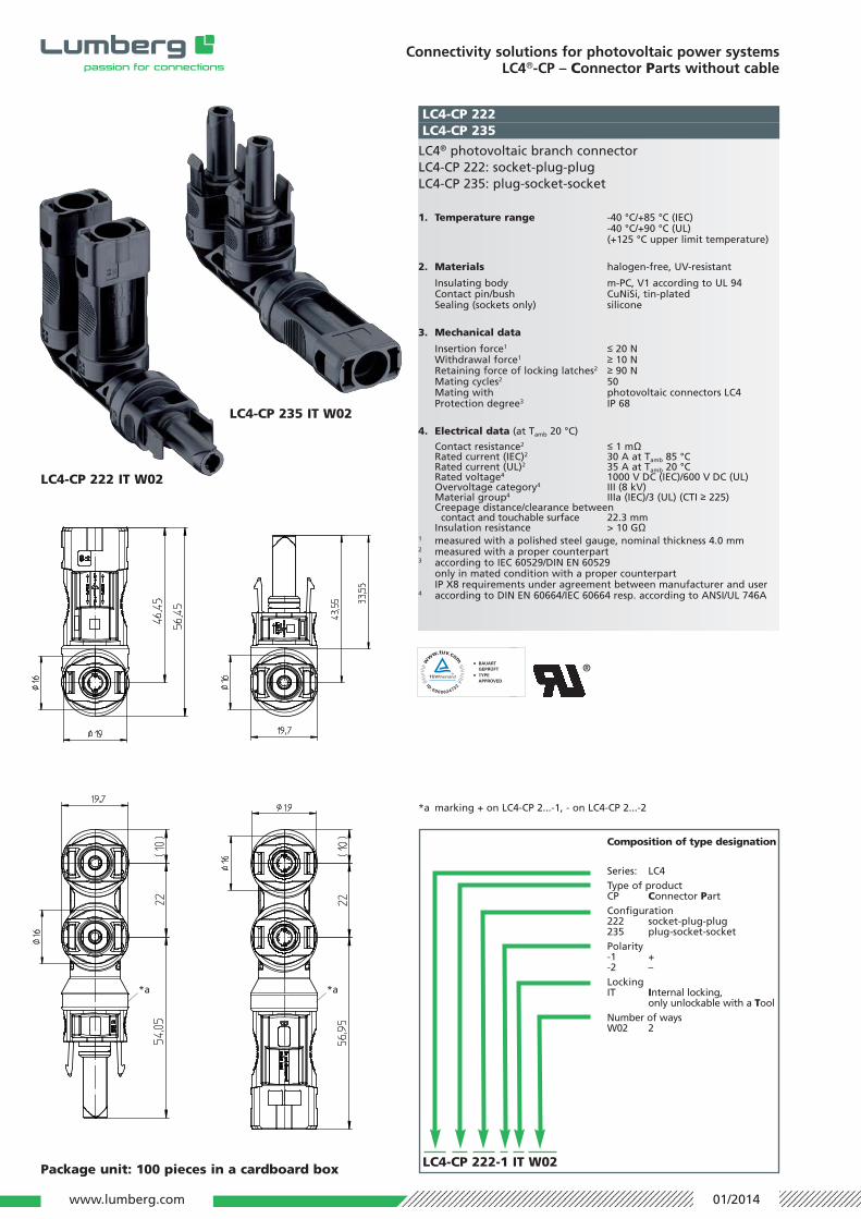
LC4-CP 222
LC4® photovoltaic branch connectorLC4-CP 222: socket-plug-plugLC4-CP 235: plug-socket-socket
1. Temperature range -40 °C/+85 °C (IEC)-40 °C/+90 °C (UL)(+125 °C upper limit temperature)
2. Materials halogen-free, UV-resistant
Insulating body m-PC, V1 according to UL 94Contact pin/bush CuNiSi, tin-platedSealing (sockets only) silicone
3. Mechanical data
Insertion force1 ≤ 20 NWithdrawal force1 ≥ 10 NRetaining force of locking latches2 ≥ 90 NMating cycles2 50Mating with photovoltaic connectors LC4Protection degree3 IP 68
4. Electrical data (at Tamb 20 °C)
Contact resistance2 ≤ 1 mΩ
Rated current (IEC)2 30 A at Tamb 85 °CRated current (UL)2 35 A at Tamb 20 °CRated voltage4 1000 V DC (IEC)/600 V DC (UL)Overvoltage category4 III (8 kV)Material group4 IIIa (IEC)/3 (UL) (CTI ≥ 225)Creepage distance/clearance between
contact and touchable surface 22.3 mmInsulation resistance > 10 GΩ
1 measured with a polished steel gauge, nominal thickness 4.0 mm2 measured with a proper counterpart3 according to IEC 60529/DIN EN 60529
only in mated condition with a proper counterpartIP X8 requirements under agreement between manufacturer and user
4 according to DIN EN 60664/IEC 60664 resp. according to ANSI/UL 746A
LC4-CP 235
Composition of type designation
Series: LC4Type of productCP Connector PartConfiguration222 socket-plug-plug235 plug-socket-socketPolarity-1 +-2 –Locking IT Internal locking,
only unlockable with a ToolNumber of waysW02 2
Package unit: 100 pieces in a cardboard box
LC4-CP 222 IT W02
LC4-CP 235 IT W02
*a marking + on LC4-CP 2...-1, - on LC4-CP 2...-2
LC4-CP 222-1 IT W02
®
*a *a
www.lumberg.com 01/2014

Composition of type designation
Series: LC4Type of productCP Connector PartConfiguration fuse with connectors950 plug-plugLockingIT Internal locking,
only unlockable with a ToolSpecification of built-in fuseRated currentRated voltage
Connectivity solutions for photovoltaic power systemsLC4®-CP – Connector Parts without cable
Package unit: 100 pieces in a cardboard box
LC4® in-line fuse connector assembly for photovoltaicinstallations1, overmolded, plug-plug
1. Temperature range -40 °C/+85 °C(+110 °C upper limit temperature)
2. Materials halogen-free, UV-resistant
Insulating body/housing m-PC, V1 according to UL 94Housing m-PC, V1 according to UL 94Contact pin/bush CuNiSi, tin-platedInner contacts CuNiSi, tin-platedSealing (sockets only) silicone
3. Mechanical dataInsertion force2 ≤ 20 NWithdrawal force2 ≥ 10 NRetaining force of locking latches2 ≥ 90 NMating cycles2 50Mating with photovoltaic connectors LC4Protection degree3 IP 68
4. Electrical data (at Tamb 20 °C)
Contact resistance ≤ 5 mΩRated current and voltage various fuses available,
values depending on type of fuse, details upon request
Overvoltage category4 III (8 kV)Material group4 IIIa (IEC)/3 (UL) (CTI ≥ 225)Creepage distance/clearance2 between
contact and touchable surface 28.3 mmInsulation resistance > 10 GΩ
1 according to application class A of IEC 61730-1/UL 17032 measured with a proper counterpart3 according to IEC 60529/DIN EN 60529
only in mated condition with a proper counterpartIP X8 requirements under agreement between manufacturer and user
4 according to DIN EN 60664/IEC 60664 resp. according to ANSI/UL 746A
LC4-CP 950 IT FUxx xxA xxxV
Designation
LC4-CP 950 IT FU01 2A 600VLC4-CP 950 IT FU02 10A 900V
LC4-CP 950
LC4-CP 950 IT
www.lumberg.com 01/2014

Connectivity solutions for photovoltaic power systemsLC4®-CP – Connector Parts without cable
Package unit: 100 pieces in a cardboard box
LC4® in-line fuse connector assembly for photovoltaicinstallations1, overmolded, plug-socket
1. Temperature range -40 °C/+85 °C(+110 °C upper limit temperature)
2. Materials halogen-free, UV-resistant
Insulating body/housing m-PC, V1 according to UL 94Housing m-PC, V1 according to UL 94Contact pin/bush CuNiSi, tin-platedInner contacts CuNiSi, tin-platedSealing (sockets only) silicone
3. Mechanical dataInsertion force2 ≤ 20 NWithdrawal force2 ≥ 10 NRetaining force of locking latches2 ≥ 90 NMating cycles2 50Mating with photovoltaic connectors LC4Protection degree3 IP 68
4. Electrical data (at Tamb 20 °C)
Contact resistance ≤ 5 mΩRated current and voltage various fuses available,
values depending on type of fuse, details upon request
Overvoltage category4 III (8 kV)Material group4 IIIa (IEC)/3 (UL) (CTI ≥ 225)Creepage distance/clearance2 between
contact and touchable surface 28.3 mmInsulation resistance > 10 GΩ
1 according to application class A of IEC 61730-1/UL 17032 measured with a proper counterpart3 according to IEC 60529/DIN EN 60529
only in mated condition with a proper counterpartIP X8 requirements under agreement between manufacturer and user
4 according to DIN EN 60664/IEC 60664 resp. according to ANSI/UL 746A
LC4-CP 952 IT FUxx xxA xxxV
Designation
LC4-CP 952 IT FU01 2A 600VLC4-CP 952 IT FU02 10A 900V
LC4-CP 952
LC4-CP 952 IT
Composition of type designation
Series: LC4Type of productCP Connector PartConfiguration fuse with connectors950 plug-plug952 plug-socketLockingIT Internal locking,
only unlockable with a ToolSpecification of built-in fuseRated currentRated voltage
www.lumberg.com 01/2014

Composition of type designation
Series: LC4Type of productCP Connector PartConfiguration diode with connectors970 plug-plugLockingIT Internal locking,
only unlockable with a ToolSpecification of built-in diodeRated currentRated voltage
Connectivity solutions for photovoltaic power systemsLC4®-CP – Connector Parts without cable
Package unit: 100 pieces in a cardboard box
LC4® in-line diode connector assembly for photovoltaicinstallations1, overmolded, plug-plug
1. Temperature range -40 °C/+85 °C(+110 °C upper limit temperature)
2. Materials halogen-free, UV-resistant
Insulating body/housing m-PC, V1 according to UL 94Housing m-PC, V1 according to UL 94Contact pin/bush CuNiSi, tin-platedInner contacts CuNiSi, tin-platedSealing (sockets only) silicone
3. Mechanical dataInsertion force2 ≤ 20 NWithdrawal force2 ≥ 10 NRetaining force of locking latches2 ≥ 90 NMating cycles2 50Mating with photovoltaic connectors LC4Protection degree3 IP 68
4. Electrical data (at Tamb 20 °C)
Contact resistance ≤ 5 mΩRated current and voltage various diodes available,
values depending on type of diode, details upon request
Overvoltage category4 III (8 kV)Material group4 IIIa (IEC)/3 (UL) (CTI ≥ 225)Creepage distance/clearance2 between
contact and touchable surface 28.3 mmInsulation resistance > 10 GΩ
1 according to application class A of IEC 61730-1/UL 17032 measured with a proper counterpart3 according to IEC 60529/DIN EN 60529
only in mated condition with a proper counterpartIP X8 requirements under agreement between manufacturer and user
4 according to DIN EN 60664/IEC 60664 resp. according to ANSI/UL 746A
LC4-CP 970 IT Dxx xxA xxxxV
*a embossment identifying the cathode side
Designation
LC4-CP 970
LC4-CP 970 IT D02 4A 1000V
*a
LC4-CP 970 IT
www.lumberg.com 01/2014
www.lumberg.com
Connectivity solutions for photovoltaic power systemsLC4®-CP – Connector Parts without cable
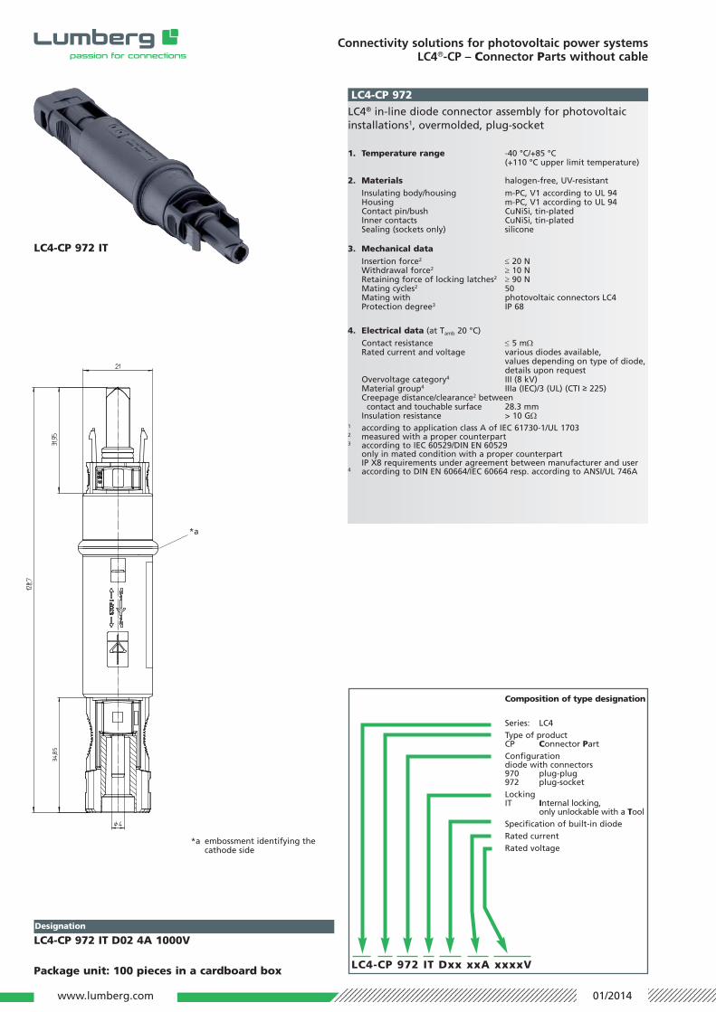
LC4-CP 972
*a embossment identifying the cathode side
Package unit: 100 pieces in a cardboard box
LC4® in-line diode connector assembly for photovoltaicinstallations1, overmolded, plug-socket
1. Temperature range -40 °C/+85 °C(+110 °C upper limit temperature)
2. Materials halogen-free, UV-resistant
Insulating body/housing m-PC, V1 according to UL 94Housing m-PC, V1 according to UL 94Contact pin/bush CuNiSi, tin-platedInner contacts CuNiSi, tin-platedSealing (sockets only) silicone
3. Mechanical dataInsertion force2 ≤ 20 NWithdrawal force2 ≥ 10 NRetaining force of locking latches2 ≥ 90 NMating cycles2 50Mating with photovoltaic connectors LC4Protection degree3 IP 68
4. Electrical data (at Tamb 20 °C)
Contact resistance ≤ 5 mΩRated current and voltage various diodes available,
values depending on type of diode, details upon request
Overvoltage category4 III (8 kV)Material group4 IIIa (IEC)/3 (UL) (CTI ≥ 225)Creepage distance/clearance2 between
contact and touchable surface 28.3 mmInsulation resistance > 10 GΩ
1 according to application class A of IEC 61730-1/UL 17032 measured with a proper counterpart3 according to IEC 60529/DIN EN 60529
only in mated condition with a proper counterpartIP X8 requirements under agreement between manufacturer and user
4 according to DIN EN 60664/IEC 60664 resp. according to ANSI/UL 746A
LC4-CP 972 IT Dxx xxA xxxxV
Designation
LC4-CP 972 IT D02 4A 1000V
*a
LC4-CP 972 IT
Composition of type designation
Series: LC4Type of productCP Connector PartConfiguration diode with connectors970 plug-plug972 plug-socketLockingIT Internal locking,
only unlockable with a ToolSpecification of built-in diodeRated currentRated voltage
01/2014

www.lumberg.com 01/2014
Connectivity solutions for photovoltaic power systemsLC4®-CX – Connector auXiliaries
LC4-CX 91LC4-CX 92
Protective cap for LC4® photovoltaic connectorsLC4-CX 91: for socketsLC4-CX 92: for plugs
1. Materials
Cap PPE/PSSealing silicone
Package unit: 100 pieces in a cardboard box
LC4-CX 93
Unlocking tool for LC4® photovoltaic connectors IT, alsowrench for field-attachable connectors and chassis recep-tacles LC4-CP
Designation Description
LC4-CX 91 for socketsLC4-CX 92 for plugs
Designation Description
LC4-CX 93 unlocking tool, wrench
Manual crimp tool for termination of LC4® photovoltaicconnectors with crimp contacts, with contact positioner
1. Range of applications
Photovoltaic connectors LC4-CP 1..., LC4-CP 3...Connectable conductors crimp terminalPhotovoltaic cable, double-insulated1
Section 2.5 mm2 (AWG 14)4.0 mm2 (AWG 12)6.0 mm2 (AWG 10)
2. FeaturesApplication low-volume production, installation,
repairStroke capacity ca. 240/h
3. Dimensions
Dimensions (H x W x D) 50 mm x 95 mm x 205 mmWeight ca. 0.7 kg
1 wire construction preferably according to IEC 60228 class 5, otherwise crimp connection must be tested
LC4-CX CZK48
Designation Description
LC4-CX CZK48 crimp tool
LC4-CX 91 LC4-CX 92

www.lumberg.com 01/2014
Connectivity solutions for photovoltaic power systemsLC4®-CX – Connector auXiliaries
Important notice Lumberg products can be used according to the characteristics speci fied in the data sheet.Beyond that, all applicable regulations, standards and directives for the use of theseproducts and for the intended appli cation must be obeyed by the user. It is the user’sresponsibility to en sure the appropriateness of a chosen Lumberg product for the intend-ed application.
Connector systems with crimp connection and high protection degrees require suitablecables and accurate processing. In order to assure safe function of the connectors theymust be processed with Lumberg harnessing equipment according to Lumberg harnessinginstructions, using cables approved by Lumberg. On the Internet (www.lumberg.com) achoice of „Approved cables“ is available for every type of connector.
Due to continuous development of Lumberg products, serving technical progress, thedescriptions and data provided hereafter are for information only and subject to changewith out notice.
We will be pleased to discuss de tail ed requirements.
Pneumatic processing machine for termination of LC4® photovoltaic connectors with crimp contacts
1. Range of applications
Photovoltaic connectors LC4-CP 1..., LC4-CP 3...Connectable conductors crimp terminalPhotovoltaic cable, double-insulated1
Section 2.5 mm2 (AWG 14)4.0 mm2 (AWG 12)6.0 mm2 (AWG 10)
2. Features
Applications middle and high-volume productionMachine cycle 1 sStroke capacity ca 600/h
- Integrated counter- Stroke release by security foot switch
3. Dimensions and supply data
Dimensions (HxW xD) 500 mm x 280 mm x 325 mmWeight ca 30 kgElectric power supply 230 V/50 HzCompressed air supply 6 bar
1 wire construction preferably according to IEC 60228 class 5, otherwise crimp connection must be tested
LC4-CX CM48
Additional automated
solutions upon request
