phys225 lecture 20 -...
TRANSCRIPT

PHYS225Lecture 20
Electronic Circuits

Last lecture
• Power Supplies and Voltage Regulation
• Critical “components” of any circuit– Must be stable and reliable
• Batteries are stable, but require replacement
• Power supplies– AC into DC with a rectifier and Zener diode
– Use an IC for better stability• LM78XX/LM79XX (XX=voltage out)
• LM317/LM337 for an adjustable supply
– Switching supplies are efficient, but noisy

Digital Electronics
• Most widespread electronics in the world
• Appears in nearly every device– Phones
– Cars
– Televisions
– Etc.
• Large scale deployment of digital electronics has changed the world– Roughly 1018 equivalent components exist

Digital Electronics
• Digital Electronics represents information (0, 1) with only two discrete values.
• Ideally “no voltage” (e.g., 0v) represents a 0 and “full source voltage” (e.g., 5v) represents a 1
• Realistically “low voltage” (e.g., <1v) represents a 0 and “high voltage” (e.g., >4v) represents a 1
• We achieve these discrete values by using switches.
• We use transistor switches, which operates at high speed, electronically, a small in size.

Analog versus Digital
• Analog systems process time-varying signals thatcan take on any value across a continuous rangeof voltages (in electrical/electronics systems).
• Digital systems process time-varying signals that can take on only one of two discrete values of voltages (in electrical/electronics systems).
– Discrete values are called 1 and 0 (ON and OFF, HIGHand LOW, TRUE and FALSE, etc.)

Representing Information Electronically
• “Analog electronics” deals with non-discrete values
– Any value of the potential
– Any current
– etc.
– Represents what we want to measure in the Universe
• “Digital electronics” deals with discrete values
– Compact representation of analog information
– How high can you count on your hands?

Benefits of Digital over Analog
• Reproducibility
• Not effected by noise means quality
• Ease of design
• Data protection
• Programmable
• Speed
• Economy

Digital Revolution
• Digital systems started back in 1940s.
• Digital systems cover all areas of life:
– still pictures
– digital video
– digital audio
– telephone
– traffic lights
– Animation

Digital Devices
• Gates
• Flip-Flops
• PLDs
• FPGAs

Gates
• The most basic digital devices are called gates.
• Gates got their name from their function ofallowing or blocking (gating) the flow of digitalinformation.
• A gate has one or more inputs and produces anoutput depending on the input(s).
• A gate is called a combinational circuit.
• Three most important gates are: AND, OR, NOT

Digital Logic• Binary system -- 0 & 1, LOW & HIGH,
negated and asserted.
• Basic building blocks -- AND, OR, NOT

AND, OR, NOT Gates


Basic Digital Element in Electronics
a Switch

Using Switch to represent digital information

Digital Abstraction
• It is difficult to make ideal switches means aswitch is completely ON or completely OFF.
• So, we impose some rules that allow analogbehavior to be ignored in most cases, so circuitscan be modeled as if they really did process 0sand 1s, known as digital abstraction.
• Digital abstraction allows us to associate a noisemargin with each logic values (0 and 1).

Real Switches to represent digital information
5v 5v
1k
10k
5v 4.5v
Output Output
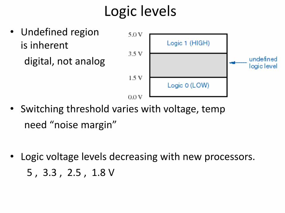
Logic levels• Undefined region
is inherent
digital, not analog
• Switching threshold varies with voltage, temp
need “noise margin”
• Logic voltage levels decreasing with new processors.
5 , 3.3 , 2.5 , 1.8 V

MOS Transistors
NMOS
PMOS
Voltage-controlled resistance

CMOS Inverter

Switch model
Flip-flops
• A device that stores either a 0 or 1.
• Stored value can be changed only at certaintimes determined by a clock input.
• New value depend on the current state and it’scontrol inputs
• A digital circuit that contains filp-flops is called asequential circuit

Flip-flops
S-R latch symbols D flip-flop
J-K flip-flops

Integrated Circuits
• A collection of one or more gates fabricated on asingle silicon chip is called an integrated circuit(IC).
• ICs were classified by size:– SSI - small scale integration - 1~20 gates
– MSI - medium scale integration - 20~200 gates
– LSI - large scale integration - 200~200,000 gates
– VLSI - very large scale integration - over 1Mtransistors
• Count has grown exponentially– Roughly doubles every 24 months

Moore’s Law

DIP Packages

Gates in ICs

Programmable Logic Devices
• PLDs allow the function to be programmed intothem after they are manufactured.
• Complex PLDs (CPLD) are a collection of PLDs onthe same chip.
• Another programmable logic chip is FPGA - field-programmable gate arrays.

CPLDs and FPGAs
FPGACPLD

Application Specific ICs (ASICs)
• Chips designed for a particular application arecalled semicustom ICs or application-specific ICs(ASICs).
• ASICs generally reduce the total component andmanufacturing cost of a product by reducing chipcount, physical size, and power consumption,and they often provide higher performance.
• But costly if not produced in bulk.
Printed-Circuit Boards
• An IC is normally mounted on a printed-circuitboard (PCB) that connects it to other ICs in asystem.
• Individual wire connection or traces can be asnarrow as 4 mils with 4 mils spacing (one-thousandth of an inch)
• Now a days, most of the components use surfacemount technology.
• They are normally layered.

Software Aspects of Digital Design
• Today software tools are an essential part of digital design.
• Software tools improve productivity, correctness and quality of designs
• Software tools are:
– Schematic entry
– HDL (Hardware Description Language) Editors
– Simulators - to verify the behaviour of the design
– Synthesis tools - circuit design
– Timing analyzers and verifiers

Digital Design Levels
• the lowest level of design is device physics and ICmanufacturing processes.
• design at the transistor level
• level of functional building blocks
• level of logic design using HDLs
• computer design and overall system design.

Different Design Levels
Consider a simple design example:
Build a multiplexer with two data inputs A and B, acontrol input S, and an output Z.
Switch model for the example multiplexer

Designing at the transistor level
• Transistor-levelcircuit diagrams
• Gate symbols (for simple elements)

• Logic designusing Truth tables

• Logic designusing boolean algebra
Equations: Z = S A + S B
• Logic diagrams

• Prepackaged building blocks, e.g. multiplexer

Programming digital devices

Assembly Language
• Low level programming– Microcontrollers
– Microprocessors
– Programmable devices
• One level higher than “machine code”– Difficult for a human to read
– Uses simple mnemonics for instructions• MOV for move to a location
• An “assembler” is used to convert AL to machine code

Assembly Language (6800)

Used to be popular!