physical property measurement systemphysical property measurement system resistivity option user’s...
TRANSCRIPT

Physical Property Measurement System
Resistivity Option User’s Manual
Part Number 1076-100A
Quantum Design 11578 Sorrento Valley Rd. San Diego, CA 92121-1311 USA Technical support (858) 481-4400 (800) 289-6996 Fax (858) 481-7410 Second edition of manual completed August 1999.
Trademarks All product and company names appearing in this manual are trademarks or registered trademarks of their respective holders.
U.S. Patents 4,791,788 Method for Obtaining Improved Temperature Regulation When Using Liquid Helium Cooling 4,848,093 Apparatus and Method for Regulating Temperature in a Cryogenic Test Chamber 5,311,125 Magnetic Property Characterization System Employing a Single Sensing Coil Arrangement to Measure AC
Susceptibility and DC Moment of a Sample (patent licensed from Lakeshore) 5,647,228 Apparatus and Method for Regulating Temperature in Cryogenic Test Chamber 5,798,641 Torque Magnetometer Utilizing Integrated Piezoresistive Levers
Foreign Patents U.K. 9713380.5 Apparatus and Method for Regulating Temperature in Cryogenic Test Chamber
Quantum Design PPMS Resistivity Option User’s Manual i
C O N T E N T S
Table of Contents PREFACE Contents and Conventions ...............................................................................................................................vii
P.1 Introduction .......................................................................................................................................................vii P.2 Scope of the Manual..........................................................................................................................................vii P.3 Contents of the Manual .....................................................................................................................................vii P.4 Conventions in the Manual...............................................................................................................................viii
CHAPTER 1 Introduction to the Resistivity Option ....................................................................................................1-1
1.1 Introduction ....................................................................................................................................................1-1 1.2 Overview of the Resistivity Option ................................................................................................................1-1
1.2.1 Advantage of Four-Wire Resistance Measurements ...............................................................................1-2 1.3 Resistivity Option Software............................................................................................................................1-2
1.3.1 Activating the Resistivity Software .........................................................................................................1-2 1.3.2 Resistivity Control Center .......................................................................................................................1-3
CHAPTER 2 User Bridge Board Operation ....................................................................................................................2-1
2.1 Introduction ....................................................................................................................................................2-1 2.2 Function of the User Bridge Board.................................................................................................................2-1
2.2.1 Limits and Resolution..............................................................................................................................2-3 2.2.2 Internal Excitation Current Range Selection ...........................................................................................2-4 2.2.3 Calibration Modes ...................................................................................................................................2-4
2.2.3.1 Fast Mode .........................................................................................................................................2-4 2.2.3.2 Standard Mode..................................................................................................................................2-5 2.2.3.3 High-Resolution Mode .....................................................................................................................2-5
2.2.4 Drive Modes ............................................................................................................................................2-6 2.2.5 Internal Voltage Gain Control .................................................................................................................2-7 2.2.6 A/D Converter Calibration ......................................................................................................................2-7
2.3 Changing User Bridge Board Settings............................................................................................................2-8 2.3.1 Using the Bridge Channels Dialog Box to Change Bridge Settings........................................................2-9 2.3.2 Using the Bridge Configuration Tab to Change Bridge Settings ..........................................................2-10 2.3.3 Using the Model 6000 to Change Bridge Settings ................................................................................2-11
2.4 Description of User Bridge Board Operation ...............................................................................................2-11

Contents Table of Contents
ii PPMS Resistivity Option User’s Manual Quantum Design
CHAPTER 3 Four-Wire Resistance Measurements .....................................................................................................3-1
3.1 Introduction ....................................................................................................................................................3-1 3.2 Sample-Mounting Procedures ........................................................................................................................3-1 3.3 Taking Four-Wire Resistance Measurements.................................................................................................3-2
3.3.1 Taking Single-Point Resistance Measurements........................................................................................ 3-3 3.3.1.1 Taking Measurements in Immediate Mode ......................................................................................3-3 3.3.1.2 Taking Measurements in Sequence Mode ........................................................................................3-4
3.3.2 Taking Multiple Resistance Measurements .............................................................................................. 3-6 3.3.2.1 Taking Measurements in Immediate Mode ......................................................................................3-6 3.3.2.2 Taking Measurements in Sequence Mode ........................................................................................3-7
3.4 Resistivity Data Files......................................................................................................................................3-9 3.4.1 Creating a Resistivity Data File ................................................................................................................ 3-9 3.4.2 Selecting a Resistivity Data File............................................................................................................. 3-10 3.4.3 Adding a Comment to a Resistivity Data File ........................................................................................ 3-11 3.4.4 Changing Resistivity Data Files during a Sequence Run ....................................................................... 3-11
CHAPTER 4 Operation with the Helium-3 System ......................................................................................................4-1
4.1 Introduction ....................................................................................................................................................4-1 4.2 Overview of Resistivity Operation with the Helium-3 System ......................................................................4-1 4.3 Resistivity Measurements with the Helium-3 System ....................................................................................4-2
4.3.1 Measurement Setup .................................................................................................................................4-2 4.3.1.1 Prepare for the Measurement............................................................................................................4-2 4.3.1.2 Install the Sample .............................................................................................................................4-3 4.3.1.3 Start Up the Software .......................................................................................................................4-3
4.3.2 Performing Measurements.......................................................................................................................4-4 4.3.2.1 Reserved Channel 3 ..........................................................................................................................4-4 4.3.2.2 Excitation Levels ..............................................................................................................................4-4 4.3.2.3 Unused Bridge Channels ..................................................................................................................4-4
CHAPTER 5 Operation with the Horizontal Rotator ..................................................................................................5-1
5.1 Introduction ....................................................................................................................................................5-1 5.2 Overview of Resistivity Operation with the Horizontal Rotator ....................................................................5-1 5.3 Resistivity Measurements with the Horizontal Rotator ..................................................................................5-2
5.3.1 Measurement Setup .................................................................................................................................5-2 5.3.1.1 Prepare for the Measurement............................................................................................................5-2 5.3.1.2 Install the Sample .............................................................................................................................5-2 5.3.1.3 Start Up the Software .......................................................................................................................5-3 5.3.1.4 Configure the Rotator .......................................................................................................................5-3
5.3.2 Performing Measurements.......................................................................................................................5-3 5.3.3 Turning Off UserTemp............................................................................................................................5-3

Contents Table of Contents
Quantum Design PPMS Resistivity Option User’s Manual iii
APPENDIX A Installation......................................................................................................................................................... A-1
A.1 Introduction ..................................................................................................................................................A-1 A.2 Installing the User Bridge Board ..................................................................................................................A-1
A.2.1 Remove the Model 6000 Cover .............................................................................................................A-1 A.2.2 Install the User Bridge Board ................................................................................................................A-2
References..............................................................................................................................................References-1 Index ................................................................................................................................................................ Index-1
Contents Table of Figures
iv PPMS Resistivity Option User’s Manual Quantum Design
Figures Figure 1-1. Interface on Resistivity Sample Puck ...................................................................................................1-1 Figure 1-2. Example of Four-Wire Resistance Measurement. ................................................................................1-2 Figure 1-3. Option Manager Dialog Box.................................................................................................................1-2 Figure 1-4. Resistivity Control Center ....................................................................................................................1-3 Figure 2-1. Block Diagram of Bridge Board...........................................................................................................2-3 Figure 2-2. Number of Measurements Averaged in High-Resolution Mode ..........................................................2-6 Figure 2-3. Bridge Channels Dialog Box ................................................................................................................2-9 Figure 2-4. Bridge Configuration Tab in Resistivity Dialog Box .........................................................................2-10 Figure 2-5. Allowed Measurement Parameters V and I. ........................................................................................ 2-12 Figure 3-1. Resistivity Sample Puck with Three Samples.......................................................................................3-1 Figure 3-2. Resistivity Control Center ....................................................................................................................3-2 Figure 3-3. Resistivity Quick Measure Dialog Box ................................................................................................3-3 Figure 3-4. Bridge Configuration Tab in Resistivity Dialog Box ...........................................................................3-4 Figure 3-5. Data Fields Tab in Resistivity Dialog Box ...........................................................................................3-5 Figure 3-6. Scan Excitation Quick Measure Dialog Box ........................................................................................3-6 Figure 3-7. Scan Setup Tab in Scan Excitation Dialog Box....................................................................................3-7 Figure 3-8. File and Sample Properties Dialog Box..............................................................................................3-10 Figure 3-9. Datafile Comment Dialog Box for Immediate Mode .........................................................................3-11 Figure 4-1. User Bridge Cable.................................................................................................................................4-2 Figure 4-2. Helium-3 Sample Puck with Two Samples. .........................................................................................4-3 Figure 5-1. Resistance Bridge Sample Holder Board with Two Samples...............................................................5-2 Figure A-1. Model 6000 PPMS Controller with Cover Removed .........................................................................A-3
Contents Table of Tables
Quantum Design PPMS Resistivity Option User’s Manual v
Tables Table 2-1. Sample Connections with User Bridge Cable Connected ......................................................................2-2 Table 2-2. Current, Power, and Voltage Limits.......................................................................................................2-3 Table 2-3. Current Ranges.......................................................................................................................................2-4 Table 2-4. Function and Suggested Use of Calibration Modes ...............................................................................2-4 Table 2-5. Voltage Gain Settings ............................................................................................................................2-7 Table 2-6. User Bridge Board Parameters...............................................................................................................2-8

Quantum Design PPMS Resistivity Option User’s Manual vii
P R E F A C E
Contents and Conventions
P.1 Introduction This preface contains the following information:
• Section P.2 discusses the overall scope of the manual.
• Section P.4 illustrates and describes conventions that appear in the manual.
• Section P.3 briefly summarizes the contents of the manual.
P.2 Scope of the Manual This manual discusses the operation of the PPMS Resistivity option hardware and software and explains how to take four-wire resistance measurements. This manual also explains how to use the Resistivity option with the PPMS Helium-3 Refrigerator System and the PPMS Horizontal Rotator.
P.3 Contents of the Manual • Chapter 1 introduces the Resistivity
option and discusses the option software. • Chapter 4 explains how to operate the
Resistivity option with the Helium-3 Refrigerator System option.
• Chapter 2 discusses the functionality of the user bridge board and explains how to operate the user bridge board.
• Chapter 5 explains how to operate the Resistivity option with the Horizontal Rotator option.
• Chapter 3 explains how to take four-wire resistance measurements.
• Appendix A explains how to install the user bridge board in the Model 6000 PPMS Controller.

Section P.4 Preface Conventions in the Manual Contents and Conventions
viii PPMS Resistivity Option User’s Manual Quantum Design
P.4 Conventions in the Manual File menu Bold text distinguishes the names of menus, options, buttons, and panels appearing
on the PC monitor or on the Model 6000 PPMS Controller LCD screen.
File Open The symbol indicates that you select multiple, nested software options.
STATUS Bold text and all capital letters distinguish the names of keys located on the front panel of the Model 6000 PPMS Controller.
.dat The Courier font distinguishes characters you enter from the PC keyboard or from the Model 6000 PPMS Controller front panel. The Courier font also distinguishes code and the names of files and directories.
<Enter> Angle brackets distinguish the names of keys located on the PC keyboard.
<Alt+Enter> A plus sign connecting the names of two or more keys distinguishes keys you press simultaneously.
A pointing hand introduces a supplementary note.
An exclamation point inside an inverted triangle introduces a cautionary note.
A lightning bolt inside an inverted triangle introduces a warning.

Quantum Design PPMS Resistivity Option User’s Manual 1-1
C H A P T E R 1
Introduction to the Resistivity Option
1.1 Introduction This chapter contains the following information:
• Section 1.2 presents an overview of the PPMS Resistivity option.
• Section 1.3 discusses the Resistivity option software.
1.2 Overview of the Resistivity Option The Resistivity option for the Physical Property Measurement System (PPMS) adds a configurable resistance bridge board, called the user bridge board, to the Model 6000 PPMS Controller. None of the four channels on the user bridge board are dedicated to a specific system operation, so all four channels are available to perform four-wire resistance measurements on the PPMS. The Resistivity option can report resistance as well as resistivity, conductance, and conductivity.
Samples for four-wire resistance measurements may be mounted on standard PPMS sample pucks (see figure 1-2) or on Resistivity sample pucks, which are included with the Resistivity option. Resistivity sample pucks have four contacts⎯one positive and one negative contact for current and voltage⎯for each user bridge board channel to which a sample may be conventionally wired (figure 1-1). Up to three samples may be mounted on a Resistivity puck, so the Resistivity option may measure up to three samples at one time. Section 3.2 discusses in detail how you mount a sample on a Resistivity puck.
Figure 1-1. Interface on Resistivity Sample Puck
Section 1.3 Chapter 1 Resistivity Option Software Introduction to the Resistivity Option
1-2 PPMS Resistivity Option User’s Manual Quantum Design
1.2.1 Advantage of Four-Wire Resistance Measurements Using four wires to attach a sample to a sample puck greatly reduces the contribution of the leads and joints to the resistance measurement. In a four-wire resistance measurement, current is passed through a sample via two current leads, and two separate voltage leads measure the potential difference across the sample (figure 1-2). The voltmeter has a very high impedance, so the voltage leads draw very little current. In theory, a perfect voltmeter draws no current whatsoever. Therefore, by using the four-wire method, it is possible to know, to a high degree of certainty, both the current and the voltage drop across the sample and thus calculate the resistance with Ohm’s law.
1.3 Resistivity Option Software The Resistivity option software is automatically installed when the PPMS MultiVu software applica-tion is installed on the control PC, and the Resistivity software is fully integrated into PPMS MultiVu, so PPMS MultiVu commands can be used to automate Resistivity system operation. However, before the Resistivity option can be used, the Resistivity software must be activated within PPMS MultiVu.
Only one measurement option may be active at a time in PPMS MultiVu, so you might have to deacti-vate another measurement option before you can activate the Resistivity option. Refer to section 1.3.1.
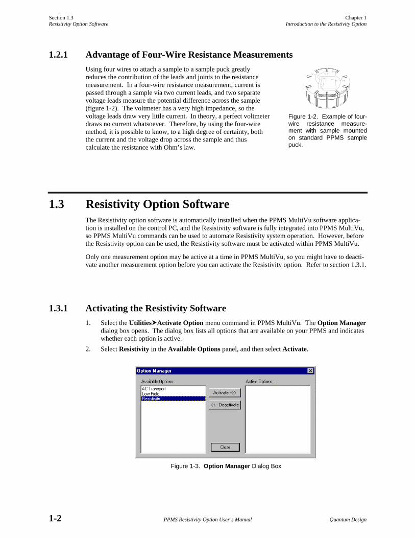
1.3.1 Activating the Resistivity Software 1. Select the Utilities Activate Option menu command in PPMS MultiVu. The Option Manager
dialog box opens. The dialog box lists all options that are available on your PPMS and indicates whether each option is active.
2. Select Resistivity in the Available Options panel, and then select Activate.
Figure 1-3. Option Manager Dialog Box
Figure 1-2. Example of four-wire resistance measure-ment with sample mounted on standard PPMS sample puck.

Chapter 1 Section 1.3 Introduction to the Resistivity Option Resistivity Option Software
Quantum Design PPMS Resistivity Option User’s Manual 1-3
Note that only one measurement option may be active at a time. An error message pops up if you attempt to activate a second measurement option. If you need to deactivate an option, select it in the Active Options panel that is in the Option Manager dialog box, and then select Deactivate.
As soon as you activate the Resistivity option, the Resistivity control center opens and the Measure menu items and measurement sequence commands that are specific to the Resistivity option appear in the PPMS MultiVu interface.
1.3.2 Resistivity Control Center The Resistivity control center makes basic system operations, such as installing samples, selecting or creating data files, and setting up and running immediate-mode resistance measurements, more natural and convenient. Automated routines initiated with control center commands prompt you to complete the necessary actions to install samples or create data files. Clearly labeled data fields indicate whether a sample is installed in the PPMS sample chamber or identify which measurement data file⎯if any⎯is selected to store Resistivity measurement data. Using the control center to perform all normal system operations is encouraged.
The Resistivity control center opens as soon as the Resistivity option is activated. The control center may be minimized, but will not close until the option is deactivated.
Figure 1-4. Resistivity Control Center
Quantum Design PPMS Resistivity Option User’s Manual 2-1
C H A P T E R 2
User Bridge Board Operation
2.1 Introduction This chapter contains the following information:
• Section 2.2 discusses the functionality of the user bridge board.
• Section 2.4 describes the operation of the user bridge board.
• Section 2.3 explains how to change the user bridge board settings.
2.2 Function of the User Bridge Board The user bridge board, which is the primary hardware component of the PPMS Resistivity option, is a nondedicated, configurable resistance bridge board. The user bridge board is installed behind and accessed through the “P1−User Bridge” port on the Model 6000 PPMS Controller. An electrical cable connects the “P1−User Bridge” port to the gray-ringed Lemo connector on the PPMS probe head and thus connects the user bridge board to the sample installed in the PPMS sample chamber. Table 2-1 identifies the electrical connections for the Resistivity option. Appendix A in the Physical Property Measurement System: Hardware Manual identifies all electrical connections used in a standard PPMS.
The user bridge board has several essential elements, as shown in figure 2-1 on page 2-3. A 12-bit (11-bit + sign) digital-to-analog converter (DAC) adjusts the excitation current up to ±5 mA. The current range and channel selection are performed internally. A 20-bit delta-sigma A/D converter reads the voltage output of the variable gain stage. The bridge board’s A/D converter contains 50-Hz and 60-Hz notch filters to reject line noise. In addition, a set of 0.01% bulk metal foil resistors is used internally as calibration resistors.
In January 1996, a new feature was added to the user bridge board. The negative current leads for each channel, which were previously tied directly to a common ground, were switched in and out of the measurement circuit like the rest of the leads. This modification allows multiple channels to be connected to the same sample without shorting out the excitation signal. User bridge boards assembled prior to 1996 do not have this capability.
In addition to the user bridge board, all PPMS units include another resistance bridge board, called the system bridge board, that is installed behind the “P2−System Bridge” port on the Model 6000 PPMS Controller. The operation of the system bridge board and user bridge board is nearly identical, but the system bridge board is essentially nonconfigurable. Three of its four channels are dedicated to system thermometry, and the fourth channel is reserved for other PPMS options. Consequently, the user bridge board must be installed to take four-wire resistance measurements.
Section 2.2 Chapter 2 Function of the User Bridge Board User Bridge Board Operation
2-2 PPMS Resistivity Option User’s Manual Quantum Design
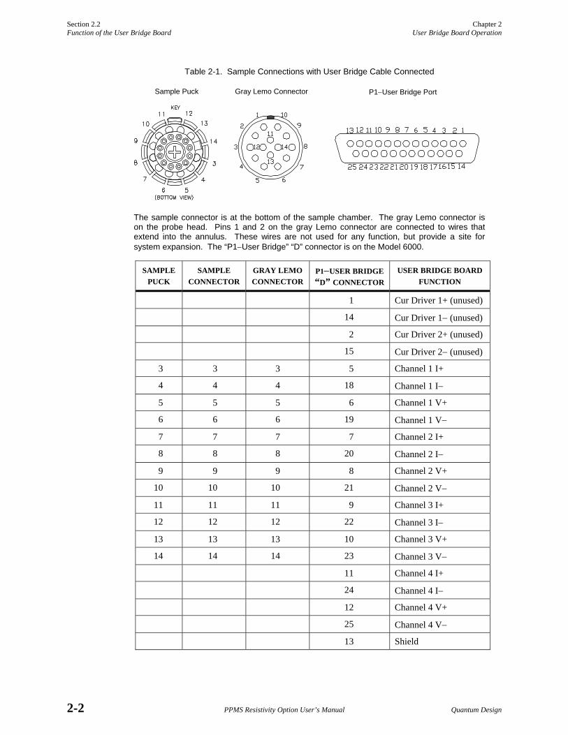
Table 2-1. Sample Connections with User Bridge Cable Connected
The sample connector is at the bottom of the sample chamber. The gray Lemo connector is on the probe head. Pins 1 and 2 on the gray Lemo connector are connected to wires that extend into the annulus. These wires are not used for any function, but provide a site for system expansion. The “P1−User Bridge” “D” connector is on the Model 6000.
SAMPLE PUCK
SAMPLE CONNECTOR
GRAY LEMO CONNECTOR
P1−USER BRIDGE “D” CONNECTOR
USER BRIDGE BOARD FUNCTION
1 Cur Driver 1+ (unused)
14 Cur Driver 1− (unused)
2 Cur Driver 2+ (unused)
15 Cur Driver 2− (unused)
3 3 3 5 Channel 1 I+
4 4 4 18 Channel 1 I−
5 5 5 6 Channel 1 V+
6 6 6 19 Channel 1 V−
7 7 7 7 Channel 2 I+
8 8 8 20 Channel 2 I−
9 9 9 8 Channel 2 V+
10 10 10 21 Channel 2 V−
11 11 11 9 Channel 3 I+
12 12 12 22 Channel 3 I−
13 13 13 10 Channel 3 V+
14 14 14 23 Channel 3 V−
11 Channel 4 I+
24 Channel 4 I−
12 Channel 4 V+
25 Channel 4 V−
13 Shield
Sample Puck Gray Lemo Connector P1−User Bridge Port

Chapter 2 Section 2.2 User Bridge Board Operation Function of the User Bridge Board
Quantum Design PPMS Resistivity Option User’s Manual 2-3
Figure 2-1. Block Diagram of Bridge Board
2.2.1 Limits and Resolution Table 2-2. Current, Power, and Voltage Limits
PARAMETER VALUES
Current Limit ±0.01−5000 µA
Power Limit 0.001−1000 µW
The user bridge board automatically adjusts the excitation current of its active channels, but you can specify the maximum allowable current, power, and voltage for each channel (see table 2-2). The excitation current is limited by the specified maximum current, voltage, or power⎯ whichever parameter setting limits the excitation current to a lower value. Voltage Limit 1−95 mV
The nominal resolution of the user bridge board is determined by the resolution of the A/D converter and by the maximum applicable current. Accordingly, nominal resolution on the most sensitive range is 3.81 nV/5.00 mA = 0.762 µΩ. In practice, environmental and internal noise sources usually limit measurement precision to around 20 nV, or 4 µΩ with a 5-mA excitation. Measurement resolution also depends on the internal gain setting and the excitation current, which can be affected by the resistance being measured and by the specified limits for current, power, and voltage.
The maximum measurable resistance is computed from the maximum potential drop that can be measured and from the minimum useful excitation current, which is determined by the user bridge’s DAC resolution. The nominal maximum measurable resistance is thus 95 mV/2.44 nA = 38.9 MΩ. However, such a measurement would require an excitation current very near the DAC resolution. In practice, user bridge board error increases drastically above approximately 4 MΩ. Errors in excess of 1% can be anticipated when measuring resistances greater than 4 MΩ. The expected error increases to 5−10% around 9 MΩ.
NOTE
The parameter ranges in this section represent the broadest limits. Current limitations set by the user-specified current, power, or voltage limit can alter these values.

Section 2.2 Chapter 2 Function of the User Bridge Board User Bridge Board Operation
2-4 PPMS Resistivity Option User’s Manual Quantum Design
2.2.2 Internal Excitation Current Range Selection Table 2-3. Current Ranges
MAXIMUM CURRENT
STEP SIZE
5.0 mA 2.44 µA
0.5 mA 244.00 nA
50.0 µA 24.40 nA
The excitation current range selection for the user bridge board is performed internally. However, it is useful to understand the range selection process. Table 2-3 lists the four excitation current ranges and the corresponding step sizes.
The bridge board uses the range resulting in the smallest step size while still providing the necessary current. For display purposes, the excitation current is rounded to the nearest step value.
Step size is calculated by 5.0 µA 2.44 nA
Step Size = Max Current211
because the excitation DAC is 11 bits (bit 12 designates the current’s sign).
2.2.3 Calibration Modes Each active channel on the user bridge board can operate in the fast, standard, or high-resolution calibration mode. The letter “F,” “S,” or “H” is displayed on the Model 6000 front panel to indicate the mode to which each channel is set. Standard mode is the default calibration mode.
Table 2-4. Function and Suggested Use of Calibration Modes
MODE DEFINITION USAGE
Fast Last measured current and voltage are read to calculate resistance. Then resistance is reported without adjusting reading.
• For resistance measurements that are part of control loop requiring quick feedback.
• To take fastest measurements. • To view noise in signals.
Standard Last measured current and voltage are read to calculate resistance. Then adjustment factor is used to recalculate and report resistance based on calibration resistor reading.
• To compensate for hardware linearity errors, drift, and offset errors.
Hi-Res Multiple standard mode readings are averaged to maintain uniform precision throughout dynamic range of instrument.
• To take high-precision measurements.
2.2.3.1 FAST MODE
In fast mode, the user bridge board reads the last measured current and voltage to directly calculate the sample resistance and then reports the resistance as quickly as possible without adjusting the reading. Fast mode generates the quickest but least accurate measurements and often produces duplicate mea-surements. Fast mode is useful when resistance measurements are part of a control loop that requires quick feedback.

Chapter 2 Section 2.2 User Bridge Board Operation Function of the User Bridge Board
Quantum Design PPMS Resistivity Option User’s Manual 2-5
2.2.3.2 STANDARD MODE
In standard mode, the user bridge board reads the last measured current and voltage to measure the sample resistance⎯just as in fast mode⎯but then applies the identical current to an appropriate calibration resistor and measures the potential drop across the resistor with the same gain in order to obtain an adjustment factor. The user bridge board then uses this adjustment factor to recalculate and report the sample resistance. By utilizing calibration resistors whenever possible, standard mode compensates for hardware linearity errors, drift, and offset errors. However, consulting a calibration resistor to complete most readings means that the user bridge channels update more slowly.
If the user bridge settings prohibit use of a calibration resistor, the measured values are not adjusted when the resistance is reported. This situation might arise, for example, when the sample resistance is either too small or too large to be used in conjunction with a calibration resistor without adjusting the gain setting. If the uppercase “S,” which denotes the standard mode setting on the Model 6000 front panel display, changes to a lowercase “s,” the reported value was not adjusted and is therefore equivalent to a reading taken in fast mode.
When operating in standard mode, the user bridge stores any adjustment factors used and reuses them for resistance calculations whenever identical measurement conditions occur on any channel within the next minute. This eliminates repetitive measurement of the calibration resistors. These adjustment factors are updated after one minute and are erased when an abort is executed, when a *CAL? GPIB command is requested, or when the power is turned off.
2.2.3.3 HIGH-RESOLUTION MODE
In high-resolution mode, the user bridge board averages multiple standard mode readings in order to maintain uniform precision throughout the range of readings. High-resolution mode helps eliminate noise from the readings and generates the most accurate but slowest resistance measurements. If the user bridge settings prohibit use of a calibration resistor, unadjusted values are averaged. The upper-case “H,” which denotes the high-resolution mode setting on the Model 6000 front panel display, changes to a lowercase “h” to indicate that unadjusted values are averaged.
The number of standard mode readings averaged to yield the reported resistance in high-resolution mode varies from 2 to 16 and depends on the divergence of the measured resistance from a base value of 32.767 Ω. The further the resistance is from the base value, the more standard mode readings are averaged to obtain the value reported. The number of readings averaged can be defined as
N Int
R
=
⎛⎝⎜
⎞⎠⎟+
⎫
⎬⎪⎪
⎭⎪⎪
⎧
⎨⎪⎪
⎩⎪⎪
log.
log32 767
22Ω ; 2 mΩ ≤ R ≤ 0.5 MΩ
N = 16; R < 2 mΩ or R > 0.5 MΩ
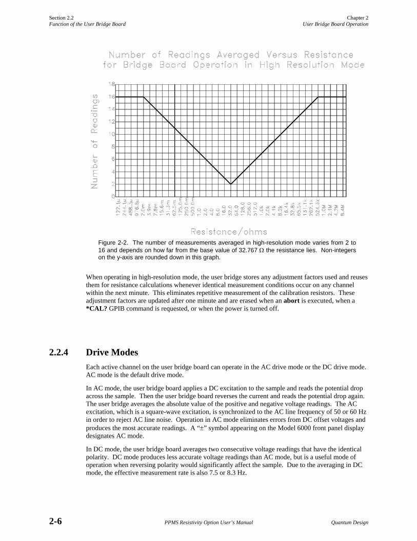
where R is the sample resistance. For resistances between 16.4 Ω and 65.5 Ω, only two standard mode readings are averaged. Resistances greater than about 0.5 MΩ or less than 2 mΩ require 16 readings, as seen in figure 2-2. For small resistances, this averaging helps eliminate noise due to a small voltage readback, and for large resistances it helps eliminate noise due to the low applied current. A measure-ment that averages 16 readings takes (7.5 Hz)-1 × 16 = 2.13 seconds. Such considerations can be important when writing a sequence file that involves data acquisition.
Section 2.2 Chapter 2 Function of the User Bridge Board User Bridge Board Operation
2-6 PPMS Resistivity Option User’s Manual Quantum Design
Figure 2-2. The number of measurements averaged in high-resolution mode varies from 2 to 16 and depends on how far from the base value of 32.767 Ω the resistance lies. Non-integers on the y-axis are rounded down in this graph.
When operating in high-resolution mode, the user bridge stores any adjustment factors used and reuses them for resistance calculations whenever identical measurement conditions occur on any channel within the next minute. This eliminates repetitive measurement of the calibration resistors. These adjustment factors are updated after one minute and are erased when an abort is executed, when a *CAL? GPIB command is requested, or when the power is turned off.
2.2.4 Drive Modes Each active channel on the user bridge board can operate in the AC drive mode or the DC drive mode. AC mode is the default drive mode.
In AC mode, the user bridge board applies a DC excitation to the sample and reads the potential drop across the sample. Then the user bridge board reverses the current and reads the potential drop again. The user bridge averages the absolute value of the positive and negative voltage readings. The AC excitation, which is a square-wave excitation, is synchronized to the AC line frequency of 50 or 60 Hz in order to reject AC line noise. Operation in AC mode eliminates errors from DC offset voltages and produces the most accurate readings. A “±” symbol appearing on the Model 6000 front panel display designates AC mode.
In DC mode, the user bridge board averages two consecutive voltage readings that have the identical polarity. DC mode produces less accurate voltage readings than AC mode, but is a useful mode of operation when reversing polarity would significantly affect the sample. Due to the averaging in DC mode, the effective measurement rate is also 7.5 or 8.3 Hz.

Chapter 2 Section 2.2 User Bridge Board Operation Function of the User Bridge Board
Quantum Design PPMS Resistivity Option User’s Manual 2-7
Both AC and DC measurements are synchronized with the power line frequency. If you are working in a 50-Hz environment instead of a 60-Hz environment, the user bridge board measures at 8.33 Hz rather than 7.5 Hz. Measurement rates are also synchronized if the power line frequency is between 45 and 70 Hz.
2.2.5 Internal Voltage Gain Control The user bridge board performs voltage gain control internally. Because the gain affects measurement resolution, an understanding of the gain control is useful.
All voltage readings are first multiplied by a factor of 25. Automatic gain control further adjusts the gain according to the measurement conditions. The gain is decreased when the A/D converter reads a voltage greater than or equal to 90% of full scale. The gain is increased when the A/D converter reads a voltage less than 9.5% of full scale. If the measured voltage falls in a zone between two gain settings, or below 9.5% of full scale on the highest setting, the gain is not adjusted.
The A/D resolution is determined by the following equation. Like the excitation DAC, the 20-bit A/D converter uses one bit to designate sign.
A / D Resolution = Full Scale219
Table 2-5 summarizes the gain settings.
Table 2-5. Voltage Gain Settings
GAIN
FULL SCALE
MAXIMUM VOLTAGE
MINIMUM VOLTAGE
A/D RESOLUTION
×1 100.0 mV 92.0 mV 9.50 mV 190.70 nV
×10 10.0 mV 9.0 mV 0.95 mV 19.07 nV
×25 4.0 mV 3.6 mV 0.38 mV 7.63 nV
×50 2.0 mV 1.8 mV ⎯ 3.81 nV
2.2.6 A/D Converter Calibration Like other A/D converters in the Model 6000, the user bridge board’s A/D converter undergoes self-calibration upon power-up. A/D converter calibration can be invoked at any time with a *CAL? remote GPIB command, and calibration automatically occurs after the abort command is received. Requesting a calibration temporarily interrupts the flow of data and the Model 6000’s control of other devices for approximately 0.5 second. For highest data integrity, a calibration should be performed before running each experiment that requires precision data. Requesting a calibration affects all PPMS A/D converters and can theoretically introduce data offsets if performed between measurements.

Section 2.3 Chapter 2 Changing the User Bridge Board Settings User Bridge Board Operation
2-8 PPMS Resistivity Option User’s Manual Quantum Design
2.3 Changing User Bridge Board Settings The Resistivity software includes multiple ways to access dialog boxes that can be used to change the current user bridge board channel settings. The Resistivity control center and the Resistivity and Scan Excitation immediate-mode measurement commands can directly open the Bridge Channels dialog box. The Resistivity and Scan Excitation sequence mode measurement commands open dialog boxes that include a Bridge Configuration tab.
The Bridge Channels dialog box (figure 2-3) shows the parameter settings for all four channels on the user bridge and indicates whether each channel is active. If a channel is active, the Bridge Channels dialog displays the current and resistance the user bridge is measuring across that channel. An active channel is always running and passing current through the sample, regardless of whether a measure-ment is being performed. Parameter settings for any active channel may be changed immediately by entering or selecting the new values and then selecting the Set button. Table 2-6 lists all user-definable parameters and identifies the acceptable parameter ranges.
The Bridge Configuration tab (figure 2-4) used to define Resistivity sequence commands also shows the parameter settings for all four user bridge channels. However, the Bridge Configuration tab indicates a channel is active only if the tab was previously used to activate the channel, and like all sequence mode dialog boxes, the Bridge Configuration tab does not display status information. Parameter settings for any channel activated in the Bridge Configuration tab may be changed in the tab, but the new values take effect only when the sequence command is read during a sequence run. If the tab is used simply to activate or deactivate a channel, the state of the channel changes only when the sequence command is read during the sequence run.
CAUTION
An approach algorithm allows the initial excitation to exceed the specified power and voltage limits for one-fifteenth of a second when the sample resistance is greater than 1 kΩ. For this reason, it is important to estimate the sample resistance before taking measurements, and for delicate samples expected to have resistances greater than 1 kΩ, only a current limit that will not exceed the samples’ expected power or voltage limit should be specified when first activating a channel.
NOTE
The excitation current of an active user bridge channel is limited by the specified maximum excitation current, voltage limit, or power limit⎯ whichever parameter limits the excitation current to a lower value.
Table 2-6. User Bridge Board Parameters
PARAMETER FUNCTION DEFINED BY PARAMETER VALUES
Bridge Channel Selected channel on user bridge board. 1−4
Current Limit Maximum excitation current for user bridge channel. ±0.01−5000 µA
Power Limit Maximum power for user bridge channel. 0.001−1000 µW
Voltage Limit Maximum voltage for user bridge channel. 1−95 mV
Calibration Mode Mode of measuring resistance of sample. • Standard • Hi-Res• Fast
Drive Mode Mode of excitation current applied to sample during resistance measurement.
• AC • DC

Chapter 2 Section 2.3 User Bridge Board Operation Changing the User Bridge Board Settings
Quantum Design PPMS Resistivity Option User’s Manual 2-9
While you work with the Resistivity option, you will find using the shortcut commands that access the user bridge parameter dialog boxes directly from the control center or the measurement dialog boxes very convenient. You may also use standard PPMS MultiVu commands to change user bridge settings. The Instrument Bridge Channels menu option opens the Bridge Channels dialog box. The Bridge Setup sequence command changes user bridge settings within a running sequence. These two PPMS MultiVu commands function only if a user bridge board is installed in the Model 6000. Refer to the Physical Property Measurement System: PPMS MultiVu Application User’s Manual for a detailed discussion of all PPMS MultiVu commands and operations.
2.3.1 Using the Bridge Channels Dialog Box to Change Bridge Settings 1. Select the Bridge Setup button in the Resistivity control center or in the Resistivity Quick
Measure or Scan Excitation Quick Measure dialog box. The Bridge Channels dialog box opens. The Resistivity software gives you the option to review or change user bridge settings at any time. Selecting Bridge Setup in the measurement dialog boxes lets you change user bridge settings while you are defining a measurement. You may close the Resistivity Quick Measure or Scan Excitation Quick Measure dialog box and keep the Bridge Channels dialog box open.
Figure 2-3. Bridge Channels Dialog Box
2. Verify that the user bridge channel or channels whose parameter settings you want to change are activated. Activate channels as necessary by clicking on the appropriate Channel On check boxes so that a check mark appears in the check boxes. In figure 2-3, all four channels are activated. If you want to deactivate a channel, click once on the appropriate Channel On check box so that the check mark disappears.
3. Set the maximum excitation current for each channel as necessary. Specifying a current limit of zero for any channel deactivates the channel. Table 2-6 and the Bridge Channels dialog box identify the acceptable parameter ranges. Notice that as soon as you change a parameter value for any channel, the channel’s Set button in the Bridge Channels dialog box is enabled.
4. Set the power limit for each channel as necessary. Specifying a power limit of zero for any channel deactivates the channel.
5. Set the voltage limit for each channel as necessary.
Section 2.3 Chapter 2 Changing the User Bridge Board Settings User Bridge Board Operation
2-10 PPMS Resistivity Option User’s Manual Quantum Design
6. Select the calibration mode the channel uses to measure sample resistance. The standard, fast, and high-resolution modes are available. Section 2.2.3 discusses the calibration modes in detail. Table 2-4 suggests possible uses for each mode.
7. Select the drive mode the channel uses during the resistance measurement. The AC and DC drive modes are available. You are advised to use AC mode unless reversing polarity would significantly affect the sample. Section 2.2.4 discusses the drive modes in detail.
8. Select the enabled Set button for each channel in order to put the changes you have made into effect. Changes to all other controls, including deactivating the Channel On check box, are initiated only when you select Set.
9. Select Close if you want to close the Bridge Channels dialog box.
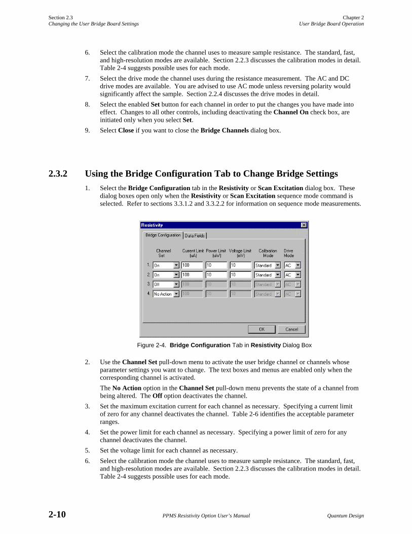
2.3.2 Using the Bridge Configuration Tab to Change Bridge Settings 1. Select the Bridge Configuration tab in the Resistivity or Scan Excitation dialog box. These
dialog boxes open only when the Resistivity or Scan Excitation sequence mode command is selected. Refer to sections 3.3.1.2 and 3.3.2.2 for information on sequence mode measurements.
Figure 2-4. Bridge Configuration Tab in Resistivity Dialog Box
2. Use the Channel Set pull-down menu to activate the user bridge channel or channels whose parameter settings you want to change. The text boxes and menus are enabled only when the corresponding channel is activated. The No Action option in the Channel Set pull-down menu prevents the state of a channel from being altered. The Off option deactivates the channel.
3. Set the maximum excitation current for each channel as necessary. Specifying a current limit of zero for any channel deactivates the channel. Table 2-6 identifies the acceptable parameter ranges.
4. Set the power limit for each channel as necessary. Specifying a power limit of zero for any channel deactivates the channel.
5. Set the voltage limit for each channel as necessary. 6. Select the calibration mode the channel uses to measure sample resistance. The standard, fast,
and high-resolution modes are available. Section 2.2.3 discusses the calibration modes in detail. Table 2-4 suggests possible uses for each mode.

Chapter 2 Section 2.4 User Bridge Board Operation Description of User Bridge Board Operation
Quantum Design PPMS Resistivity Option User’s Manual 2-11
7. Select the drive mode the channel uses during the resistance measurement. The AC and DC drive modes are available. You are advised to use AC mode unless reversing polarity would significantly affect the sample. Section 2.2.4 discusses the drive modes in detail.
8. Select the other tab or tabs in the dialog box and finish defining the measurement, if necessary. Refer to sections 3.3.1.2 and 3.3.2.2.
9. Select OK. The Resistivity or Scan Excitation command is added to the selected sequence file. The new parameter settings go into effect when the command is read while the sequence runs.
2.3.3 Using the Model 6000 to Change Bridge Settings You may also use the Model 6000 Setup Bridge Channel screen to change user bridge board settings. To open the Setup Bridge Channel screen, you select the STATUS-BRIDGE screen and then select setup, or you enter the CONTROL menu and select 3. Immediate Operations 06: Bridge. In the Setup Bridge Channel screen, you press incr and decr to choose a bridge channel. Then you adjust the current limit, power limit, voltage limit, calibration mode, and drive mode as necessary. Once the settings are correct, press EXEC <Alt+Enter> to execute them.
The Model 6000 STATUS-BRIDGE screen normally displays the status⎯including resistance, excitation current, calibration mode, and drive mode⎯of each user bridge channel. However, you can configure the Model 6000 to show the status of the system bridge board channels and calibration channels. To do this, enter the CONFIG menu and select 5. Software. Then select 3. Diagnostics and change the Bridge Display Channel setting to the appropriate display. The standard setting displays the four user bridge channels. Once this display is reconfigured, it becomes possible to change system bridge settings simply by selecting setup from the STATUS-BRIDGE screen. Note, though, that because these channels are used for PPMS temperature control, changing their settings is not recommended.
2.4 Description of User Bridge Board Operation After any new user bridge board channel settings are executed, excitation current is applied to each active channel, beginning with the lowest numbered channel. If a channel was operating before the new configuration was executed, the user bridge assumes that the resistance has not changed in order to predict the measurement parameters I and V and set the initial excitation current. The initial excitation current is usually the specified current limit. If this current would cause the power to exceed the specified power limit with a 1-kΩ resistance, the user bridge uses a 1-kΩ initial resistance estimate for the first cycle of an approach algorithm. Accordingly, a settling time of a few seconds may be required to reach a stable excitation current. This can be another important consideration when writing sequence files.
At equilibrium, the excitation current equals the current limit setting unless the power limit setting or voltage limit setting is reached. It is important to understand the range of possible excitation currents and potential drops across the sample. You choose the maximum allowable current, voltage, and power through the sample, so measurement parameters are confined to the dark lines in the graph in figure 2-5. When the power limit is set greater than 460 µW, only the current and voltage limit settings should affect the measurement parameters.

Section 2.4 Chapter 2 Description of User Bridge Board Operation User Bridge Board Operation
2-12 PPMS Resistivity Option User’s Manual Quantum Design
The voltage drop across the sample is read twice⎯with the same polarity excitation each time for DC mode, and with opposite polarities for AC mode⎯and the resistance is reported according to one of the three calibration modes. Enabled channels are scanned sequentially and then necessary calibration channels are read. In standard mode, the resistance is not reported until the appropriate calibration resistor has been measured (if this is possible). When a channel is in high-resolution mode, other channels continue to operate as usual, but a resistance is reported for only the high-resolution channel after an appropriate number of readings has been recorded and averaged.
The user bridge board has one current source and voltage detector. Consequently, measurements do not actually occur simultaneously, although the measurements occur so close to each other you really will not notice that they are not simultaneous. On a normal PPMS configured for measurements on three user bridge channels, the first channel measured is 1, and the last channel measured is 3.
An active user bridge board channel is always running and passing current through the sample, regardless of whether a measurement is being performed.
0 1 2 3 4 50
20
40
60
80
100
PossibleMeasurementParameters
92
Vmax
Typical R
esistan
ce Curve
Actual MeasurementParameters
Abso
lute
Cur
rent
Lim
it
Absolute Voltage Limit
Allowable Measurement Parameters
V (m
V)
I (mA)
Imax
V=Pmax/I
Figure 2-5. The allowed measurement parameters V and I are constrained by the user-specified voltage limit (Vmax), current limit (Imax), and power (Pmax). This plot shows Vmax = 82 mV, Imax = 4.2 mA, and Pmax = 0.2 mW.
Quantum Design PPMS Resistivity Option User’s Manual 3-1
C H A P T E R 3
Four-Wire Resistance Measurements
3.1 Introduction This chapter contains the following information:
• Section 3.2 explains how to mount samples on Resistivity sample pucks.
• Section 3.4 discusses the function of Resistivity data files.
• Section 3.3 explains how to take four-wire resistance measurements.
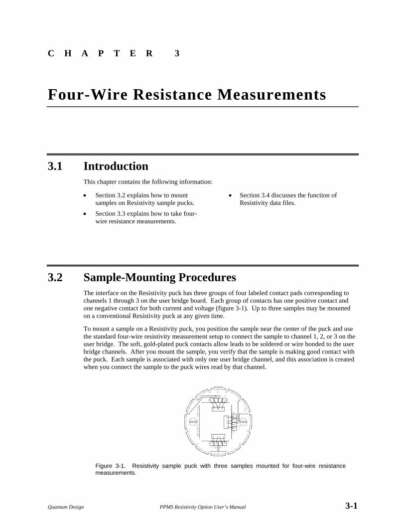
3.2 Sample-Mounting Procedures The interface on the Resistivity puck has three groups of four labeled contact pads corresponding to channels 1 through 3 on the user bridge board. Each group of contacts has one positive contact and one negative contact for both current and voltage (figure 3-1). Up to three samples may be mounted on a conventional Resistivity puck at any given time.
To mount a sample on a Resistivity puck, you position the sample near the center of the puck and use the standard four-wire resistivity measurement setup to connect the sample to channel 1, 2, or 3 on the user bridge. The soft, gold-plated puck contacts allow leads to be soldered or wire bonded to the user bridge channels. After you mount the sample, you verify that the sample is making good contact with the puck. Each sample is associated with only one user bridge channel, and this association is created when you connect the sample to the puck wires read by that channel.
Figure 3-1. Resistivity sample puck with three samples mounted for four-wire resistance measurements.

Section 3.3 Chapter 3 Taking Four-Wire Resistance Measurements Four-Wire Resistance Measurements
3-2 PPMS Resistivity Option User’s Manual Quantum Design
The Resistivity puck does not include contacts for user bridge channel 4 because channel 4 is not prewired for sample measurements. The 12 pins at the bottom of the PPMS sample chamber allow three samples to be measured; four pins are required to measure one sample. Consequently, user bridge channels 1 through 3 normally take measurements.
The Resistivity option may also be used with standard PPMS sample pucks. When you use the standard sample puck, refer to table 2-1 to determine the correct wiring.
3.3 Taking Four-Wire Resistance Measurements Resistance can be measured once, or it can automatically be measured with a number of excitation currents in a given excitation current range. The Resistivity command takes one resistance measure-ment. The Scan Excitation command takes measurements throughout a specified excitation range. Resistivity and Scan Excitation can be executed immediately or included in a PPMS MultiVu sequence file.
CAUTION
An approach algorithm allows the initial excitation to exceed the specified power and voltage limits for one-fifteenth of a second when the sample resistance is greater than 1 kΩ. For this reason, it is important to estimate the sample resistance before taking measurements, and for delicate samples expected to have resistances greater than 1 kΩ, only a current limit that will not exceed the samples’ expected power or voltage limit should be specified when first activating a channel.
Before you measure resistance, you must (1) mount the sample on a puck and wire the sample to a user bridge channel; (2) insert the sample into the sample chamber by selecting the Install/Remove button in the Resistivity control center and following the pop-up instructions; and (3) select or create a new Resistivity data file, if necessary. Section 3.2 explains how you mount samples on Resistivity pucks. Section 3.4.1 explains how you create a data file. Section 3.4.2 explains how you select a data file.
For all normal system operations⎯installing samples, selecting data files, and taking immediate-mode measurements⎯you are encouraged to use the Resistivity control center. The auto-mated routines in the control center help ensure that you complete the necessary procedures when you install samples or create data files. The examples of measurements in this chapter illustrate use of the control center.
NOTE
Each sample is associated with one user bridge board channel. The sample’s association with a specific channel is identified in the data file header and cannot be changed in PPMS MultiVu. If you change the samples on a puck, insert a new puck, or wire a sample to some other channel, you must create a new data file to ensure that the integrity of the stored data is maintained.
Figure 3-2. Resistivity Control
Center

Chapter 3 Section 3.3 Four-Wire Resistance Measurements Taking Four-Wire Resistance Measurements
Quantum Design PPMS Resistivity Option User’s Manual 3-3
3.3.1 Taking Single-Point Resistance Measurements The Resistivity command, which takes one resistance measurement at the current system conditions, can be executed immediately from the Resistivity control center or the PPMS MultiVu Measure menu or it can be included in a sequence.
3.3.1.1 TAKING MEASUREMENTS IN IMMEDIATE MODE
After you insert the sample into the sample chamber and select the data file (see section 3.3), you can define and then run the measurement. Complete the following steps:
1. Select the Measure button in the Resistivity control center or select the Resistivity option in the Measure menu. The Resistivity Quick Measure dialog box opens. Items in the Control panel on the left side of the dialog box designate measurement conditions that should be set prior to running the measurement. Items in the Results panel on the right side of the dialog box display the results of the last single-point resistance measurement that was run in immediate mode.
Figure 3-3. Resistivity Quick Measure Dialog Box
2. Select the Channel check boxes representing the user bridge channels you want to read. Any number of channels may be read. If you select channels to which no sample is wired, a value of zero is reported when the measurement is complete.
3. Enter, in the Readings text box, the number of readings you want the system to take and average for one measurement. The readings are averaged regardless of the calibration mode, so if the channel uses high-resolution mode (see section 2.2.3.3), the operations specific to that mode are performed first, before the Resistivity software averages the readings.
4. Select the Bridge Setup button if you want to review or change user bridge settings. A channel must be active to be measured. Section 2.3 explains how you change user bridge settings.
5. Select Measure. The measurement begins. The Measure button reads Cancel during the mea-surement. You select Cancel to abort the measurement. When the measurement is complete, the Resistivity Quick Measure dialog box displays the measurement results as well as the average temperature, magnetic field, and sample position used during the measurement. Resistivity and excitation are reported, in the measurement units that were specified when the data file was created, for the measured channels. Values of zero excita-tion and zero resistivity are reported for those channels to which no sample is wired.

Section 3.3 Chapter 3 Taking Four-Wire Resistance Measurements Four-Wire Resistance Measurements
3-4 PPMS Resistivity Option User’s Manual Quantum Design
6. Select the Save button in the Resistivity Quick Measure dialog if you want to save the measure-ment results to the specified data file. You must select Save in order to save the data. The Save button is disabled after you select it, and it remains disabled until another single-point resistance measurement runs. The button is also disabled if a data file has not been selected.
7. Select Close if you want to close the Resistivity Quick Measure dialog box.
If you saved the measurement data, you may find it useful to examine the data. Clicking on the View button in the Resistivity control center opens the graph view of the selected data file. Once the graph view is open, you may select many different graph formats to plot the data, or you may select various other data-viewing formats. The Physical Property Measurement System: PPMS MultiVu Application User’s Manual discusses data-viewing formats and graph formats in detail.
3.3.1.2 TAKING MEASUREMENTS IN SEQUENCE MODE
After you insert the sample into the sample chamber and select the data file (see section 3.3), you can run a sequence that includes the Resistivity command. A Resistivity data file must be selected in order to run a sequence that includes the Resistivity or Scan Excitation command.
Complete the following steps to take a resistance measurement in sequence mode. You should refer to the Physical Property Measurement System: PPMS MultiVu Application User’s Manual for a detailed discussion of sequence operation.
1. Select the New Sequence File button in the PPMS MultiVu tool bar. A new sequence file is created. The sequence command bar also opens.
2. Select the Resistivity command in the Measurement Commands group that is in the sequence command bar. The Resistivity dialog box opens and displays the Bridge Configuration tab.
Figure 3-4. Bridge Configuration Tab in Resistivity Dialog Box
3. Use the Channel Set pull-down menu in the Bridge Configuration tab to activate the user bridge channels you want to read. Any number of channels may be read. You may use the No Action option to prevent the channel state from being altered when the command is executed.
4. Change the settings of the active user bridge channels as necessary. Section 2.3 explains how you change user bridge settings. When you use the Resistivity sequence command to activate user bridge channels, the resistivity and excitation read off the activated channels are saved to the data file, and the data items for the activated channels are automatically selected in the Data Fields tab (see figure 3-5). When a user bridge channel is deactivated⎯that is, set to Off⎯no data can be collected for that channel.

Chapter 3 Section 3.3 Four-Wire Resistance Measurements Taking Four-Wire Resistance Measurements
Quantum Design PPMS Resistivity Option User’s Manual 3-5
5. Use the Data Fields tab to select the system data items you want to save to the data file. By default, the general system status, temperature, magnetic field, and sample position are selected to be saved. The resistivity and excitation read off the active channels are also saved to the file.
Figure 3-5. Data Fields Tab in Resistivity Dialog Box
6. Enter, in the Reading Count text box, the number of readings you want the system to take and average for one measurement. The readings are averaged regardless of the calibration mode, so if the channel uses high-resolution mode (see section 2.2.3.3), the operations specific to that mode are performed first, before the Resistivity software averages the readings.
7. Select OK to add the Resistivity command to the sequence. 8. Select the Save Sequence File button in the PPMS MultiVu tool bar, type a file name for your
sequence, and then select Save in the pop-up dialog box. 9. Select the Run Sequence button in the PPMS MultiVu tool bar. You saved your new sequence
and selected a data file, so the sequence should run immediately. Status messages in the PPMS MultiVu interface indicate that a sequence is running. The commands in the sequence determine the length of time the sequence runs. The Resistivity command you included in the sequence is executed when it is read during the sequence run.

Section 3.3 Chapter 3 Taking Four-Wire Resistance Measurements Four-Wire Resistance Measurements
3-6 PPMS Resistivity Option User’s Manual Quantum Design
3.3.2 Taking Multiple Resistance Measurements The Scan Excitation command, which takes resistance measurements throughout a specified excita-tion range, can be executed immediately from the PPMS MultiVu Measure menu or it can be included in a sequence. Resistance measurements taken with Scan Excitation are actually taken one at a time, although the measurements may be read so rapidly they appear to be taken simultaneously.
3.3.2.1 TAKING MEASUREMENTS IN IMMEDIATE MODE
After you insert the sample into the sample chamber and select the data file (see section 3.3), you can define and then run the measurement. Complete the following steps:
1. Select Measure Scan Excitation. The Scan Excitation Quick Measure dialog box opens. Items in the Control panel on the left side of the dialog box designate mea-surement conditions that should be set prior to running the measurement. Items in the System panel on the right side of the dialog box indicate what the values of key system parameters were during the last multiple-point resistance measurement run in immediate mode.
2. Select the Channel option representing the user bridge channel you want to read.
3. Use the Initial text box to specify the starting current in the excitation range. Notice that when you change the excitation range, the value of Delta, which is the excitation step size, is adjusted.
4. Use the Final text box to specify the final current in the excitation range. 5. Change the value of Delta, if necessary. If you change Delta, the Steps value is adjusted. 6. Use the Steps text box to specify the number of different excitation currents at which measure-
ments are read in the excitation range. Specifying the number of steps is not mandatory. If you change the number of steps, the Delta value is adjusted.
7. Use the Spacing pull-down menu to select the mode of spacing the steps. Linear mode, which is the default, evenly spaces the steps. Logarithmic mode logarithmically spaces the steps. Power mode separates the steps by i2.
8. Enter, in the Readings text box, the number of readings you want the system to take and average at each step in the excitation range. The readings are averaged regardless of the calibration mode, so if the channel uses high-resolution mode (see section 2.2.3.3), the operations specific to that mode are performed first, before the Resistivity software averages the readings.
9. Select the Bridge Setup button if you want to review or change user bridge settings. A channel must be active to be measured. Section 2.3 explains how you change user bridge settings.
10. Select Measure. The measurement begins. The Measure button reads Cancel during the mea-surement. You select Cancel to abort the measurement. As soon as the measurement is complete, the Scan Excitation Quick Measure dialog box displays the average temperature, magnetic field, and sample position used during the measure-ment, as well as the number of readings taken and the elapsed time of the measurement. The actual number of readings taken during the measurement is shown in the Actual Readings panel.
Figure 3-6. Scan Excitation Quick Measure
Dialog Box

Chapter 3 Section 3.3 Four-Wire Resistance Measurements Taking Four-Wire Resistance Measurements
Quantum Design PPMS Resistivity Option User’s Manual 3-7
11. Select the View button in the Scan Excitation Quick Measure dialog box if you want to open the qd_resistivity_temporary.dat file and see a plot of the measurement. View opens the file only when a Resistivity data file is selected to store data and a multiple-point resistance measurement has just been run in immediate mode. The qd_resistivity_temporary.dat file is overwritten each time another multiple-point resistance measurement runs in immediate mode.
12. Select the Save button in the Scan Excitation Quick Measure dialog if you want to save the measurement results to the specified data file. You must select Save in order to save the data. The Save button is disabled after you select it and remains disabled until another multiple-point resistance measurement runs. The button is also disabled if a data file has not been not selected.
13. Select Close if you want to close the Scan Excitation Quick Measure dialog box.
3.3.2.2 TAKING MEASUREMENTS IN SEQUENCE MODE
After you insert the sample into the sample chamber and select the data file (see section 3.3), you can run a sequence that includes the Scan Excitation command. A Resistivity data file must be selected in order to run a sequence that includes the Resistivity or Scan Excitation command.
The Scan Excitation sequence command functions similarly to other PPMS MultiVu scan commands. When the system reads Scan Excitation in a running sequence, it takes measurements, on all active user bridge channels, throughout the entire excitation range before executing the next command in the sequence. Scan Excitation thus simplifies the process of scanning through an excitation range, and by reducing the number of commands in a sequence, Scan Excitation helps prevent the sequence file from getting too large. However, Scan Excitation, unlike other scan commands, creates a one-line control loop into which no additional commands may be inserted. Refer to the Physical Property Measurement System: PPMS MultiVu Application User’s Manual for a detailed discussion of scan commands and control loop operation.
Complete the following steps to take multiple resistance measurements in sequence mode. You should refer to the Physical Property Measurement System: PPMS MultiVu Application User’s Manual for a detailed discussion of sequence operation.
1. Select the New Sequence File button in the PPMS MultiVu tool bar. A new sequence file is created. The sequence command bar also opens.
2. Select the Scan Excitation command in the Measurement Commands group that is in the sequence command bar. The Scan Excitation dialog box opens and displays the Scan Setup tab.
Figure 3-7. Scan Setup Tab in Scan Excitation Dialog Box

Section 3.3 Chapter 3 Taking Four-Wire Resistance Measurements Four-Wire Resistance Measurements
3-8 PPMS Resistivity Option User’s Manual Quantum Design
3. Use the Scan Setup tab to define the excitation range and the mode of spacing the steps within the excitation range. See section 3.3.2.1 for an explanation of the Scan Excitation parameters.
4. Use the Channel Set pull-down menu in the Bridge Configuration tab to activate the user bridge channels you want to read. Any number of channels may be read. You may use the No Action option to prevent the channel state from being altered when the command is executed.
5. Change the settings of the active user bridge channels as necessary. Section 2.3 explains how you change user bridge settings. When you use the Scan Excitation sequence command to activate user bridge channels, the resistivity and excitation read off the activated channels are saved to the data file, and the data items for the activated channels are automatically selected in the Data Fields tab (see figure 3-5). When a user bridge channel is deactivated⎯that is, set to Off⎯no data can be collected for that channel.
6. Use the Data Fields tab to select the system data items you want to save to the data file. By default, the general system status, temperature, magnetic field, and sample position are selected to be saved. The resistivity and excitation read off the active channels are also saved to the file.
7. Enter, in the Reading Count text box, the number of readings you want the system to take and average at each step in the excitation range. The readings are averaged regardless of the cali-bration mode, so if the channel uses high-resolution mode (see section 2.2.3.3), the operations specific to that mode are performed first, before the Resistivity software averages the readings.
8. Select OK to add the Scan Excitation command to the sequence. 9. Select the Save Sequence File button in the PPMS MultiVu tool bar, type a file name for your
sequence, and then select Save in the pop-up dialog box. 10. Select the Run Sequence button in the PPMS MultiVu tool bar. You saved your new sequence
and selected a data file, so the sequence should run immediately. Status messages in the PPMS MultiVu interface indicate that a sequence is running. The commands in the sequence determine the length of time the sequence runs. The Scan Excitation command you included in the sequence is executed when it is read during the sequence run.

Chapter 3 Section 3.4 Four-Wire Resistance Measurements Resistivity Data Files
Quantum Design PPMS Resistivity Option User’s Manual 3-9
3.4 Resistivity Data Files Resistivity measurement data files store measurement results and other relevant parameters read by the Model 6000 PPMS Controller during resistance measurements. The Resistivity software creates Resistivity measurement data files and lets only Resistivity measurement data files be selected to store data from Resistivity measurements. Like any PPMS MultiVu measurement data file, Resistivity measurement data files have a .dat file extension.
By default, the Resistivity software records the following data for every measurement: the resistivity and excitation read off each measured user bridge board channel; the general PPMS status code; and the average system temperature, magnetic field, and sample position from the measurement. The two Resistivity measurement sequence commands allow you to select which PPMS system data items you want to save to the data file.
The header of each Resistivity data file includes file and sample property information that is defined at the time the data file is created. When you create a new file, the Resistivity software prompts you to define the sample properties for the sample or samples whose measurement data will be saved to the file. Information written to the data file header cannot subsequently be changed in PPMS MultiVu. Subsequently changing samples without changing the data files can destroy the validity of the data in the files.
NOTE
Each sample is associated with one user bridge channel. The sample’s association with a specific channel is identified in the data file header and cannot be changed in PPMS MultiVu. If you change the samples on a puck, insert a new puck, or wire a sample to some other channel, you must create a new data file to ensure that the integrity of the stored data is maintained.
The Datafile panel in the Resistivity control center (see figure 3-2) identifies which Resistivity measurement data file is selected to store the Resistivity measurement data, and also maps the file location. The panel is blank if a data file has not been selected.
Selecting the View button in the control center opens the graph view of the currently selected Resistivity data file. The Physical Property Measurement System: PPMS MultiVu Application User’s Manual discusses your options for plotting and viewing data.
3.4.1 Creating a Resistivity Data File 1. Select the Browse button in the Resistivity control center. The Select a Data File dialog box
opens. The dialog box lists all existing data files. 2. Select the drive and directory where the new data file will reside, if necessary. The default
directory to which PPMS MultiVu writes data files is C:\QdPpms\Data. 3. Use the File name text box in the Select a Data File dialog box to enter the name of the new
data file. Creating a name that helps identify the file as a Resistivity data file is useful. If you enter the name of an existing file, that file will be overwritten.
4. Select Open. The File and Sample Properties dialog box opens (figure 3-8), and all data entry fields in the dialog box are enabled.

Section 3.4 Chapter 3 Resistivity Data Files Four-Wire Resistance Measurements
3-10 PPMS Resistivity Option User’s Manual Quantum Design
Figure 3-8. File and Sample Properties Dialog Box
5. Use the Data File Title text box in the File and Sample Properties dialog to specify a title for the graph view of the data file, if you like. Specifying a title for the graph view is not mandatory.
6. Enter, in the Sample Description text boxes representing the user bridge channel or channels to which the installed sample or samples are connected, the following information: (a) The name or a description of each sample. (b) The area, in mm2, of each sample. Use “1” if you are uncertain what the area of the
sample is. A value of 1 will not affect the data. (c) The length, in mm, of each sample. Use “1” if you are uncertain what the length of the
sample is. A value of 1 will not affect the data. The information you enter in the File and Sample Properties dialog box is saved to the data file header. Enter the information carefully; it cannot be subsequently changed in PPMS MultiVu.
7. Select the units in which you want the measurement results reported for each channel to which a sample is connected. The units determine the specific type of data saved for that channel. In addition to the resistivity, the data file also stores the resistance for each measurement.
8. Select OK. The data file is created, and its name and file location are displayed in the Datafile panel in the Resistivity control center.
Notice that if you select the Samples button in the Resistivity control center after you create the data file, all data entry fields in the File and Sample Properties dialog box are disabled.
3.4.2 Selecting a Resistivity Data File 1. Select the Browse button in the Resistivity control center. The Select a Data File dialog box
opens. The dialog box lists all existing data files. 2. Double-click on the name of a Resistivity data file. A warning message pops up if you try to
select a file that is incompatible with the Resistivity option. As soon as you select a Resistivity data file, the File and Sample Properties dialog box opens and displays the information stored in the data file header. All data entry fields in the dialog box are disabled.
3. Review the information in the File and Sample Properties dialog box to determine whether you have selected the correct data file for your sample. If the file stores data for some other sample or for some other sample-wiring arrangement, return to step 2 and select another data file.
4. Select OK to close the File and Sample Properties dialog box and to prompt the Resistivity software to store all new measurement data in the selected data file.

Chapter 3 Section 3.4 Four-Wire Resistance Measurements Resistivity Data Files
Quantum Design PPMS Resistivity Option User’s Manual 3-11
3.4.3 Adding a Comment to a Resistivity Data File You can append a comment containing any number of characters to the selected Resistivity measure-ment data file. Because the comment is appended to only the selected data file, you should first verify that the file to which you want to append the comment is selected.
In immediate mode, you append a comment to a data file by selecting the Measure Add Datafile Comment menu option, entering the comment in the pop-up dialog box, and then selecting OK. In sequence mode, you select the Datafile Comment measurement sequence command, enter the comment, and then select OK. You may add only a comment to a data file; you may not insert a blank line into a data file.
Figure 3-9. Datafile Comment Dialog Box for Immediate Mode
3.4.4 Changing Resistivity Data Files during a Sequence Run The Resistivity option includes the Change Datafile sequence command. When the Change Datafile command is executed, it prompts the system to start saving Resistivity measurement data and the selected system parameter data to the new data file specified by the command. You can use Change Datafile to select an existing data file or to create a new data file.
Complete the following steps to change data files during a sequence run:
1. Position the highlight bar in the sequence editor so that the highlight bar marks the location where you want to insert the Change Datafile command. New commands are inserted immediately above the highlight bar. Refer to the Physical Property Measurement System: PPMS MultiVu Application User’s Manual for detailed information about sequence operation.
2. Select the Change Datafile command in the Measurement Commands group that is in the sequence command bar. The Change Datafile Sequence dialog box opens and displays the Datafile tab.
3. Select Browse. The Select a Data File dialog box opens. The dialog box lists all existing data files.
4. Select or create a data file as necessary. Refer to sections 3.4.1 and 3.4.2. As soon as you select or create a file, you see the Datafile tab in the Change Datafile Sequence dialog box again. The tab shows the file location and name of the data file you have just selected.
5. If you are selecting a data file, use the Sample tab in the Change Datafile Sequence dialog box to determine whether you have selected an appropriate data file for your sample. If the file stores data for some other sample or for some other sample-wiring arrangement, select another file.
6. Select OK to add the Change Datafile command to the sequence file.

Quantum Design PPMS Resistivity Option User’s Manual 4-1
C H A P T E R 4
Operation with the Helium-3 System
4.1 Introduction This chapter contains the following information:
• Section 4.2 presents an overview of Resistivity operation with the Helium-3 system.
• Section 4.3 describes how to take Resistivity measurements when using the Helium-3 system.
4.2 Overview of Resistivity Operation with the Helium-3 System The Resistivity option may be used with the PPMS Helium-3 Refrigerator System insert (Model P825). Use of the Helium-3 insert allows resistance measurements to be performed to below 0.4 K. Although samples are mounted differently when the Helium-3 system is being used, the operation of the Helium-3 system is otherwise designed to be as transparent as possible.
The Helium-3 option uses bridge board channel 3 for reading the Helium-3 system thermometer. Because the thermometer excitation power must be kept very low below 1 K, the enhanced bridge board (part number 3076-050) must be used. As of July 1999, the enhanced bridge board ships standard with all Resistivity options. The new enhanced bridge board has been designed with a precision-balanced current source to aid precise readings of large resistances.
To set up the system for resistance measurements, the standard user bridge cable (part number 3084-003) is connected in the usual way; that is, between the gray-ringed Lemo connector on the PPMS probe head and the “P1−User Bridge” port on the Model 6000 PPMS Controller. Because channel 3 is used for thermometry, only channels 1 and 2 are available for measurements.
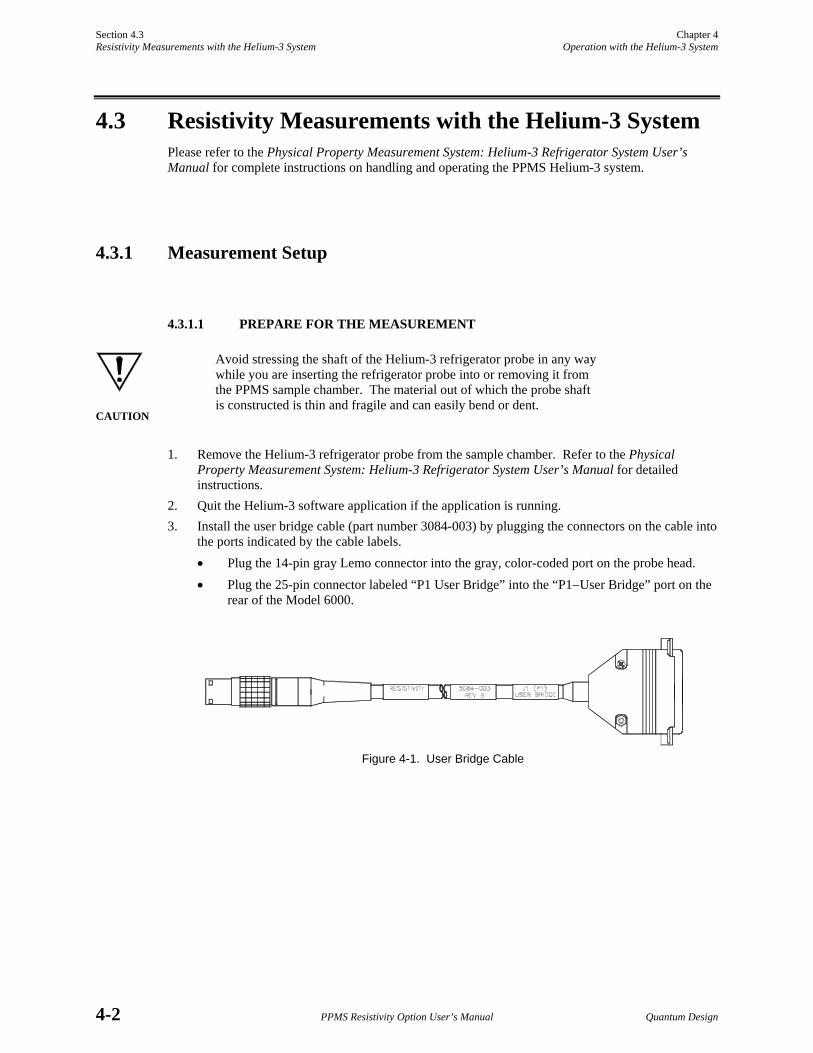
Section 4.3 Chapter 4 Resistivity Measurements with the Helium-3 System Operation with the Helium-3 System
4-2 PPMS Resistivity Option User’s Manual Quantum Design
4.3 Resistivity Measurements with the Helium-3 System Please refer to the Physical Property Measurement System: Helium-3 Refrigerator System User’s Manual for complete instructions on handling and operating the PPMS Helium-3 system.
4.3.1 Measurement Setup
4.3.1.1 PREPARE FOR THE MEASUREMENT
CAUTION
Avoid stressing the shaft of the Helium-3 refrigerator probe in any way while you are inserting the refrigerator probe into or removing it from the PPMS sample chamber. The material out of which the probe shaft is constructed is thin and fragile and can easily bend or dent.
1. Remove the Helium-3 refrigerator probe from the sample chamber. Refer to the Physical Property Measurement System: Helium-3 Refrigerator System User’s Manual for detailed instructions.
2. Quit the Helium-3 software application if the application is running. 3. Install the user bridge cable (part number 3084-003) by plugging the connectors on the cable into
the ports indicated by the cable labels. • Plug the 14-pin gray Lemo connector into the gray, color-coded port on the probe head. • Plug the 25-pin connector labeled “P1 User Bridge” into the “P1−User Bridge” port on the
rear of the Model 6000.
Figure 4-1. User Bridge Cable

Chapter 4 Section 4.3 Operation with the Helium-3 System Resistivity Measurements with the Helium-3 System
Quantum Design PPMS Resistivity Option User’s Manual 4-3
4.3.1.2 INSTALL THE SAMPLE
1. Mount the sample on a Helium-3 sample mount (part number 4092-610). Note that at temperatures below 1 K, intimate thermal contact between the sample and the copper holder is very important to reduce temperature errors. A thin film of Apiezon N Grease works well to aid thermal contact. Apiezon N Grease is supplied with the Model P825 Helium-3 insert.
2. Refer to figure 4-2 below to wire the sample to the stage. The plug-in sample mount is clearly labeled for mounting two samples.
Figure 4-2. Helium-3 sample puck with two samples mounted for four-wire resistance measurements.
3. Attach the plug-in sample stage to the Helium-3 refrigerator probe. Refer to the Physical Property Measurement System: Helium-3 Refrigerator System User’s Manual for detailed instructions.
4. Insert the Helium-3 refrigerator probe into the sample chamber. Refer to the Physical Property Measurement System: Helium-3 Refrigerator System User’s Manual for detailed instructions.
4.3.1.3 START UP THE SOFTWARE
1. Start up PPMS MultiVu if the application is not running. 2. Activate the Helium-3 option in PPMS MultiVu. Do the following: (a) select Utilities
Activate Option, (b) click on Helium3 under the Available Options heading, and then (c) select the Activate button.
3. Activate the Resistivity option in PPMS MultiVu. Do the following: (a) select Utilities Activate Option, (b) click on Resistivity under the Available Options heading, and then (c) select the Activate button. Both the Helium-3 software and Resistivity software must be running before you can initiate a measurement.
4. Initiate a Helium-3 system test by using PPMS MultiVu or the Model 6000 front panel to set an initial temperature (for example, 300 K). The Helium-3 temperature control is activated on the first Temperature Set command. The software checks out the Helium-3 system, downloads any necessary configuration data to the Model 6000 console, and begins controlling temperature.
Section 4.3 Chapter 4 Resistivity Measurements with the Helium-3 System Operation with the Helium-3 System
4-4 PPMS Resistivity Option User’s Manual Quantum Design
4.3.2 Performing Measurements Once the Helium-3 refrigerator probe is inserted in the sample chamber and the Helium-3 and Resistivity software applications are running, you may take resistance measurements at temperatures as low as 0.4 K. You take measurements and write sequences according to the usual procedures described in chapter 3. However, there are a few additional considerations for resistance measure-ments with the Helium-3 system. These considerations are described below.
4.3.2.1 RESERVED CHANNEL 3
Channel 3 on the user bridge board is used exclusively for thermometer readback with the Helium-3 system. You should never attempt to modify the settings for channel 3.
NOTE
For channel 3, you must always select No Action for the Channel Set parameter in the Resistivity sequence measurement dialog box and the Scan Excitation sequence measurement dialog box.
4.3.2.2 EXCITATION LEVELS
The sample mounts provided for mounting samples are constructed of high-conductivity copper to provide good thermal anchoring. However, at temperatures below about 1 K, it is normally very difficult to achieve good thermal contact, even within the sample itself. That is, if the excitation current is too high, significant self-heating of the sample can result in substantial temperature errors where the relevant portions of the sample are warmer than the Helium-3 thermometer reports. Again, this is not necessarily due to poor contact of the sample to the sample holder; it may be due to poor thermal conductance of the sample itself. The best way to detect this effect is to repeat measurements using different bridge-board excitation levels. It is also generally recommended that you use the smallest possible excitation that still gives an adequate signal-to-noise ratio.
4.3.2.3 UNUSED BRIDGE CHANNELS
Due to the extremely low excitation currents used for reading the thermometer on channel 3, there can be significant cross-talk from the other bridge channels under certain conditions. In the worst case, this can produce instabilities in the temperature control.
The worst case cross-talk appears when unused bridge channels are not explicitly turned off. In this case, the current drive multiplexer can create unwanted voltage spikes when switching from an open load to a neighboring channel. Therefore, always turn off unused bridge channels.

Quantum Design PPMS Resistivity Option User’s Manual 5-1
C H A P T E R 5
Operation with the Horizontal Rotator
5.1 Introduction This chapter contains the following information:
• Section 5.2 presents an overview of Resistivity operation with the Horizontal Rotator.
• Section 5.3 describes how to take Resistivity measurements when using the Horizontal Rotator.
5.2 Overview of Resistivity Operation with the Horizontal Rotator The Resistivity option may be used with the PPMS Horizontal Rotator option (Model P310). Use of the Horizontal Rotator allows the sample to be rotated around an axis perpendicular to the magnetic field of a longitudinal PPMS magnet.
The Horizontal Rotator option uses bridge board channel 1 for reading the thermometer on the rotator. Consequently, once channel 1 is configured, its settings must not be changed. Only channels 2 and 3 are available for resistance measurements.
The standard user bridge cable (part number 3084-003) is connected to both the gray-ringed Lemo connector on the PPMS probe head and the “P1−User Bridge” port on the Model 6000 PPMS Con-troller when the Resistivity option is used with the Horizontal Rotator. Figure 4-1 illustrates the user bridge cable.

Section 5.3 Chapter 5 Resistivity Measurements with the Horizontal Rotator Operation with the Horizontal Rotator
5-2 PPMS Resistivity Option User’s Manual Quantum Design
5.3 Resistivity Measurements with the Horizontal Rotator Please refer to the Physical Property Measurement System: Horizontal Rotator Option User’s Manual for complete instructions on handling and operating the PPMS Horizontal Rotator.
5.3.1 Measurement Setup
5.3.1.1 PREPARE FOR THE MEASUREMENT
1. Install the user bridge cable (see figure 4-1) by plugging the connectors on the cable into the ports indicated by the cable labels. • Plug the 14-pin gray Lemo connector into the gray, color-coded port on the probe head. • Plug the 25-pin connector labeled “P1 User Bridge” into the “P1−User Bridge” port on the
rear of the Model 6000.
5.3.1.2 INSTALL THE SAMPLE
1. Mount the sample on a resistance bridge sample holder board (part number 3084-371).
2. Refer to figure 5-1 to wire the sample to the sample holder board. The sample holder board is clearly labeled for mounting two samples.
3. Attach the sample holder board to the rotator transfer case. Refer to the Physical Property Measurement System: Horizontal Rotator Option User’s Manual for detailed instructions.
CAUTION
The Horizontal Rotator probe is delicate and must be handled with care. Use caution so that you do not dent or bend the stainless steel tube on the outside of the probe. Be extremely careful when placing the probe on a flat surface, such as a table, because the probe may easily roll off.
4. Insert the Horizontal Rotator probe into the sample chamber. Refer to the Physical Property Measurement System: Horizontal Rotator Option User’s Manual for detailed instructions.
Figure 5-1. Resistance bridge sample holder board with two samples mounted for four-wire resistance measurements.

Chapter 5 Section 5.3 Operation with the Horizontal Rotator Resistivity Measurements with the Horizontal Rotator
Quantum Design PPMS Resistivity Option User’s Manual 5-3
5.3.1.3 START UP THE SOFTWARE
1. Start up PPMS MultiVu if the application is not running. 2. Activate the Resistivity option in PPMS MultiVu. Do the following: (a) select Utilities
Activate Option, (b) click on Resistivity under the Available Options heading, and then (c) select the Activate button.
5.3.1.4 CONFIGURE THE ROTATOR
1. Download the appropriate configuration file for the rotator in order to set up the rotator thermometry and configure the rotator motor. Refer to the Physical Property Measurement System: Horizontal Rotator Option User’s Manual for detailed instructions.
2. Engage the rotator motor and check for the proper position calibration. Refer to the Physical Property Measurement System: Horizontal Rotator Option User’s Manual for detailed instructions.
5.3.2 Performing Measurements Once the Horizontal Rotator probe is inserted in the sample chamber and the Resistivity software application is running, you may take resistance measurements as you would normally. Refer to chapter 3.
5.3.3 Turning Off UserTemp Configuring the Horizontal Rotator by transmitting the configuration files to the Model 6000 ROM also turns on UserTemp so that the rotator thermometer is used for temperature control. When you complete your experiments with the Horizontal Rotator and remove the Horizontal Rotator probe from the sample chamber, you should turn off this thermometer. Complete the following steps:
1. Open Monitor QD-6000 in the PPMS 32-bit Tools folder, or select Utilities Send GPIB Commands in the PPMS MultiVu interface.
2. Type USERTEMP 0. 3. Press <Enter> to execute this command.
If you do not turn off UserTemp, the resistance read off user bridge channel 1 is used to control the temperature in the sample chamber. If UserTemp remains on, but no user thermometer is installed⎯ that is, the Horizontal Rotator probe is removed from the PPMS⎯the temperature control defaults back to the system thermometers, but returns to user bridge channel 1 whenever a resistance is perceived there. If the resistance is not that of the calibrated rotator thermometer, the temperature controller appears broken, so be sure to turn off UserTemp when you are not using the Horizontal Rotator or another customized calibrated thermometer.

Quantum Design PPMS Resistivity Option User’s Manual A-1
A P P E N D I X A
Installation
A.1 Introduction This appendix contains the following information:
• Section A.2 explains how to install the user bridge board in the Model 6000.
A.2 Installing the User Bridge Board The user bridge board that is part of the PPMS Resistivity option is generally installed at the Quantum Design factory. The board can, however, be easily installed in the field. These installation instructions explain how to install the user bridge board in the Model 6000 PPMS Controller.
The user bridge board installation kit includes the following items:
One user bridge board (part number 3076-050) Four split-ring lock washers and 4/40 hex nuts to secure user bridge board to motherboard posts Two jack sockets to secure 25-pin “D” shell connector to Model 6000 rear panel One 9 1/3-inch, 16-wire ribbon cable
A.2.1 Remove the Model 6000 Cover 1. Take all necessary precautions to protect the user bridge board against static electricity or other
electrical damage.
CAUTION
Static discharge can damage components on the user bridge board and other components inside the Model 6000. Before you touch the user bridge board or any other component inside the Model 6000, ground yourself by touching the metal back or metal side panel of the Model 6000 case. In addition, limit your movement during installation and whenever you handle the user bridge board; movement increases the possibility of static discharge.

Section A.2 Appendix A Installing the User Bridge Board Installation
A-2 PPMS Resistivity Option User’s Manual Quantum Design
2. Set the system magnetic field to zero and wait for the field to reach zero. 3. Select CTRL 1. Interactive Control 8. Shutdown Mode from the Model 6000 front panel.
The PPMS enters shutdown mode. 4. Use the switch on the front panel of the Model 6000 to turn off the Model 6000. Do not turn off
the vacuum pump or any other electronics in the PPMS electronics cabinet. 5. Clear the top of the PPMS console cabinet, and then remove the top cover of the console cabinet
by lifting it up and off the console. 6. Remove the top cover from the Model 6000 as follows:
• If only the two rear top cover screws (see “A” in figure A-1) secure the top cover, remove these screws, and then remove the top cover.
• If the two rear top cover screws (see “A” in figure A-1) and the two front top cover screws (see “B” in figure A-1) secure the top cover, do the following: (a) Unscrew the two rack mount screws that attach the Model 6000 to the console cabinet
rack. (b) Carefully slide the Model 6000 forward and out of the console approximately 2 inches
(5.13 cm). Make certain that you support the full weight of the Model 6000. (c) Remove the two front top cover screws (see “B” in figure A-1). (d) Carefully slide the Model 6000 back into the console cabinet. (e) Screw in the two rack mount screws to attach the Model 6000 mounting brackets to
the console cabinet rack. (f) Remove the two rear top cover screws (see “A” in figure A-1). (g) Remove the Model 6000 top cover.
A.2.2 Install the User Bridge Board
CAUTION
Do not drop any components inside the Model 6000. If any components are dropped inside the Model 6000, they must be retrieved before power is restored, or they may cause serious, irreparable damage.
CAUTION
Do not scrape back-plane components or traces while you install the user bridge board.
Before you install the user bridge board, refer to figure A-1 and note the location of the board in the Model 6000. When you face the Model 6000 front panel, the user bridge board is at the right rear side of the controller and is immediately adjacent to the system bridge board (see “D” in figure A-1). The user bridge board sits on four posts (see “C” in figure A-1).
Complete the following steps to install the user bridge board in the Model 6000:
1. Place the user bridge board in the Model 6000.

Appendix A Section A.2 Installation Installing the User Bridge Board
Quantum Design PPMS Resistivity Option User’s Manual A-3
The 25-pin “D” shell connector fits into the “P1−User Bridge” port located on the Model 6000 rear panel. The four holes in the board fit over the four posts secured on the motherboard.
2. Secure the connector (“P1−User Bridge”) to the rear panel by inserting the two jack sockets (see “E” in figure A-1) through the connector holes, starting from the outer side of the rear panel.
3. Secure the user bridge board to the motherboard posts by (a) placing each washer on a post, (b) placing each nut on a post, and then (c) tightening each nut.
4. Connect the four-wire ribbon cable from the system bridge board to the socket labeled J5 “DRIVER” (see “F” in figure A-1) on the user bridge board.
5. Connect the 16-wire ribbon cable as follows. (a) Connect one end of the cable to the mother-board socket labeled J13 “USER BRIDGE” (see “G” in figure A-1). (b) Connect the other end of the cable to the user bridge board socket labeled J1 “CONTROL” (see “H” in figure A-1).
6. Reinstall the top cover on the Model 6000 by securing it with only the two rear screws (see “A” in figure A-1).
7. Put the top cover back on the console cabinet. 8. Press the power button to turn on the Model 6000.
The system is now ready for normal use.
Figure A-1. Model 6000 PPMS Controller with Cover Removed

Quantum Design PPMS Resistivity Option User’s Manual References-1
References
Quantum Design. 1998. Physical Property Measurement System: Hardware Manual.
⎯⎯⎯. 1999. Physical Property Measurement System: Helium-3 Refrigerator System User’s Manual.
⎯⎯⎯. 1998. Physical Property Measurement System: Horizontal Rotator Option User’s Manual.
⎯⎯⎯. 1998. Physical Property Measurement System: PPMS MultiVu Application User’s Manual.

Quantum Design PPMS Resistivity Option User’s Manual Index-1
Index
AC mode applying excitation current to sample, 2-6. See also User bridge board: Operation as default drive mode, 2-6 recommended use of, 2-10, 2-11 synchronized with power line frequency, 2-7 as user bridge board parameter, 2-6, 2-8 A/D converter, on user bridge board, calibrating, 2-7 DC mode applying excitation current to sample, 2-6. See also User bridge board: Operation synchronized with power line frequency, 2-7 as user bridge board parameter, 2-6, 2-8 Calibration modes, as user bridge board parameter, 2-4, 2-8. See also Fast mode; High-resolution mode; Standard mode Current limit, for user bridge board, 2-3, 2-8 Drive modes, 2-6−2-7, 2-8 Enhanced bridge board, 4-1 Excitation current ranges, 2-4 Fast mode calculating sample resistance in, 2-4 suggested usage, 2-4 as user bridge board parameter, 2-4, 2-8 Four-wire resistance measurements advantage of, 1-2 extending temperature range of. See Helium-3 Refrigerator System option rotating samples for. See Horizontal Rotator option saving data from. See Resistivity data files taking multiple in immediate mode, 3-2, 3-6−3-7 in sequence mode, 3-2, 3-7−3-8 taking single point in immediate mode, 3-2, 3-3−3-4 in sequence mode, 3-2, 3-4−3-5 user bridge board channels available for, 3-1, 3-2 wiring sample for. See Helium-3 sample mount; PPMS sample puck; Resistance bridge sample holder board; Resistivity sample puck Helium-3 refrigerator probe, proper handling of, 4-2
Helium-3 Refrigerator System option extending temperature range, 4-1, 4-4 and possible cross-talk, 4-4 reserving user bridge board channel 3, 4-1, 4-4 taking four-wire resistance measurements when installed, 4-2−4-4 user bridge board channels available with, 4-1 Helium-3 sample mount, wiring sample to, 4-3 High-resolution mode. See also Standard mode calculating sample resistance in, 2-4, 2-5−2-6. See also User bridge board: Operation suggested usage, 2-4 as user bridge board parameter, 2-4, 2-8 Horizontal Rotator option and function of UserTemp, 5-3 reserving user bridge board channel 1, 5-1 rotating samples, 5-1 taking four-wire resistance measurements when installed, 5-2−5-3 user bridge board channels available with, 5-1 Horizontal Rotator probe, proper handling of, 5-2 Measurements. See Four-wire resistance measurements Model 6000 PPMS Controller changing user bridge board settings with, 2-11 connections for P1−User Bridge port, 2-2 housing user bridge board, 1-1, 2-1. See also User bridge board: Installing illustration of, with cover removed, A-3 removing cover from, A-1−A-2 Multiple resistance measurements, taking in immediate mode, 3-2, 3-6−3-7 in sequence mode, 3-2, 3-7−3-8 Nominal resolution, of user bridge board, determining, 2-3 Power limit, for user bridge board, 2-3, 2-8 PPMS measurement option, deactivating, 1-3 PPMS MultiVu application automating Resistivity operation, 1-2 commands changing user bridge board settings, 2-9 PPMS sample puck sample mounted on, illustration of, 1-2 using for four-wire resistance measurements, 1-1, 3-2 qd_resistivity_temporary.dat file, 3-7

Index
Index-2 PPMS Resistivity Option User’s Manual Quantum Design
Resistance bridge board. See System bridge board; User bridge board Resistance bridge sample holder board, wiring sample to, 5-2 Resistivity command. See Single-point resistance measurement Resistivity control center opening with Resistivity option activation, 1-3 simplifying system operation, 1-3, 3-2 Resistivity data files adding comment to, 3-11 changing during sequence run, 3-11 creating, 3-9−3-10 data stored in, 3-9 header in, and inability to change information written to, 3-2, 3-9, 3-10 opening graph view of, 3-4, 3-9 required for sequence measurements, 3-4, 3-7 saving immediate-mode data to, 3-4, 3-7 saving sequence mode data to, 3-4−3-5, 3-8, 3-9 selecting, 3-10 Resistivity option adding user bridge board to system, 1-1. See also User bridge board electrical connections, 2-2 measurement types reported by, 1-1 operation with Helium-3 Refrigerator System. See Helium-3 Refrigerator System option operation with Horizontal Rotator. See Horizontal Rotator option sample pucks used with, 1-1. See also PPMS sample puck; Resistivity sample puck Resistivity option software. See also Resistivity control center; Resistivity data files activating, 1-2−1-3 default data recorded by, 3-9 Resistivity sample puck interface, description of, 1-1, 3-1 as platform for up to three samples, 1-1, 3-1, 3-2 samples mounted on, illustration of, 3-1 wiring sample to, 1-1, 3-1−3-2 Sample and association with one user bridge board channel, 3-1, 3-2, 3-9 wiring for four-wire resistance measurement. See Helium-3 sample mount; PPMS sample puck; Resistance bridge sample holder board; Resistivity sample puck Sample resistance, estimating before measurement, 2-8, 3-2 Scan Excitation command in immediate mode, using, 3-6−3-7 in sequence mode, function of, 3-7 Single-point resistance measurement, taking
in immediate mode, 3-2, 3-3−3-4 in sequence mode, 3-2, 3-4−3-5
Standard mode. See also Fast mode
calculating sample resistance in, 2-4, 2-5. See also User bridge board: Operation as default calibration mode, 2-4 suggested usage, 2-4 as user bridge board parameter, 2-4, 2-8 Standard sample puck. See PPMS sample puck System bridge board, 2-1 User bridge board adjusting excitation current, 2-1, 2-3, 2-4, 2-11 block diagram, 2-3 calibration modes, 2-4, 2-8. See also Fast mode; High-resolution mode; Standard mode channels. See User bridge board channels drive modes, 2-6−2-7, 2-8 electrical connections, 2-2 enabling four-wire resistance measurements, 1-1, 2-1. See also Four-wire resistance measurements installing, A-1−A-3 internal voltage gain control, 2-1, 2-7 location in Model 6000 PPMS Controller, illustration of, A-3 as main component of Resistivity option, 1-1, 2-1 operation, description of, 2-11−2-12. See also User bridge board channels: Changing settings parameters changing. See User bridge board channels: Changing settings list of, 2-8. See also AC mode; DC mode; Fast mode; High-resolution mode; Standard mode User bridge board channels changing settings for in immediate mode, 2-8, 2-9−2-10 with Model 6000 PPMS Controller, 2-11 in sequence mode, 2-8, 2-9, 2-10−2-11 number of available, 1-1 parameters, list of, 2-8. See also AC mode; DC mode; Fast mode; High-resolution mode; Standard mode User bridge cable illustration of, 4-2 used with Helium-3 Refrigerator System, 4-1, 4-2 used with Horizontal Rotator, 5-1, 5-2 UserTemp, turning off, 5-3 Voltage limit, for user bridge board, 2-3, 2-8 Voltage gain settings, for user bridge board, 2-7