physical review applied 14, 034019 (2020)
TRANSCRIPT
PHYSICAL REVIEW APPLIED 14, 034019 (2020)
Thermoelectricity in Quantum Hall Corbino Structures
Mariano Real ,1,* Daniel Gresta,2 Christian Reichl,3 Jürgen Weis,4 Alejandra Tonina,1 Paula Giudici,5Liliana Arrachea,2 Werner Wegscheider,3 and Werner Dietsche3,4
1Instituto Nacional de Tecnología Industrial, INTI and INCALIN-UNSAM, Avenida General Paz 5445,
Buenos Aires 1650, Argentina2International Center for Advanced Studies, ECyT-UNSAM, 25 de Mayo y Francia, Buenos Aires 1650, Argentina
3Solid State Physics Laboratory, ETH Zürich, Zürich CH-8093, Switzerland
4Max-Plack-Institut für Festkörperforschung, Heisenbergstrasse 1, Stuttgart D-70569 Germany
5INN CNEA-CONICET, Avenida General Paz 1499, Buenos Aires 1650, Argentina
(Received 11 March 2020; revised 10 August 2020; accepted 14 August 2020; published 8 September 2020)
We measure the thermoelectric response of Corbino structures in the quantum Hall effect regime andcompare it with a theoretical analysis. The measured thermoelectric voltages are qualitatively and quan-titatively simulated based upon the independent measurement of the conductivity, indicating that theyoriginate predominantly from the electron diffusion. In contrast to earlier Hall-bar experiments, electron-phonon interaction does not lead to a phonon-drag contribution. This implies a description of the Onsagercoefficients on the basis of a single transmission function, from which both thermovoltage and conductiv-ity can be predicted with a single fitting parameter. Furthermore, it lets us predict a figure of merit for theefficiency of thermoelectric cooling, which becomes very large for partially filled Landau levels and highmagnetic fields.
DOI: 10.1103/PhysRevApplied.14.034019
I. INTRODUCTION
The quantum Hall effect (QHE), which occurs in two-dimensional electron systems (2DES) exposed to quantiz-ing magnetic fields, is one of the most prominent examplesof the synergy between fundamental physics and quantumtechnologies [1]. It is topological in nature and intrinsicallyrelated to exotic properties of matter, such as fractionaliza-tion and non-Abelian statistics [2–4]. At the same time,these complex properties are precisely the reason for itsrobustness and appeal for practical applications. It is nowa-days at the heart of the definition of the electrical metrolog-ical standards [5], while it is also a promising platform forthe development of topological quantum computation [6].
Measurements of the entropy would be of great impor-tance in verifying the theoretically expected quantumstates, particularly of the non-Abelian ones. One possibil-ity to access entropy in a 2DES is to measure the thermo-electricity [7,8]. However, although thermoelectricity hasbeen studied both experimentally and theoretically sincethe discovery of the integer QHE [9–11], it has not beenpossible to reconcile the experimental results obtained withHall bars [Fig. 1(a)] with theories based upon electron dif-fusion. The overwhelming effect of phonon drag has been
invoked as one reason [9,10,12] but, more recently, inher-ent problems connected with the topology of the Hall-bargeometry, affecting both phonon drag and electron diffu-sion, have been realized [8]. The longitudinal thermopower(or Seebeck coefficient) measured along a Hall bar closelyresembles the longitudinal resistance, both in the phonondrag and in the diffusive regime, while an oscillatingbehavior with sign changes is expected by the theory. It hasbeen suggested that the longitudinal thermopower couldbe measured correctly in Corbino geometry [Fig. 1(b)]where, due to the circular geometry, the thermal bias isapplied radially; hence any thermal and electrical transportis induced along the radial direction [13] and the transporttakes place through the bulk.
Early thermopower experiments in Corbino geometryhave failed to observe the expected sign-changing behavior[14]. It has been reported, however, in other experimentalworks using the Corbino geometry [15]. The latter haveused rf heating of the 2DES to produce the temperaturegradient directly in the 2DES, claiming that no phononsare involved in the measured thermopower.
In this paper, we report Corbino thermopower measure-ments in the QHE regime by using a conventional heater inthe center of the device. In this way, a temperature gradi-ent is set up in both the substrate and the 2DES. Results attemperatures from about 300 mK to 2 K are presented andcompared with theoretical results, where both the electrical
2331-7019/20/14(3)/034019(8) 034019-1 © 2020 American Physical Society

MARIANO REAL et al. PHYS. REV. APPLIED 14, 034019 (2020)
(a) (b)
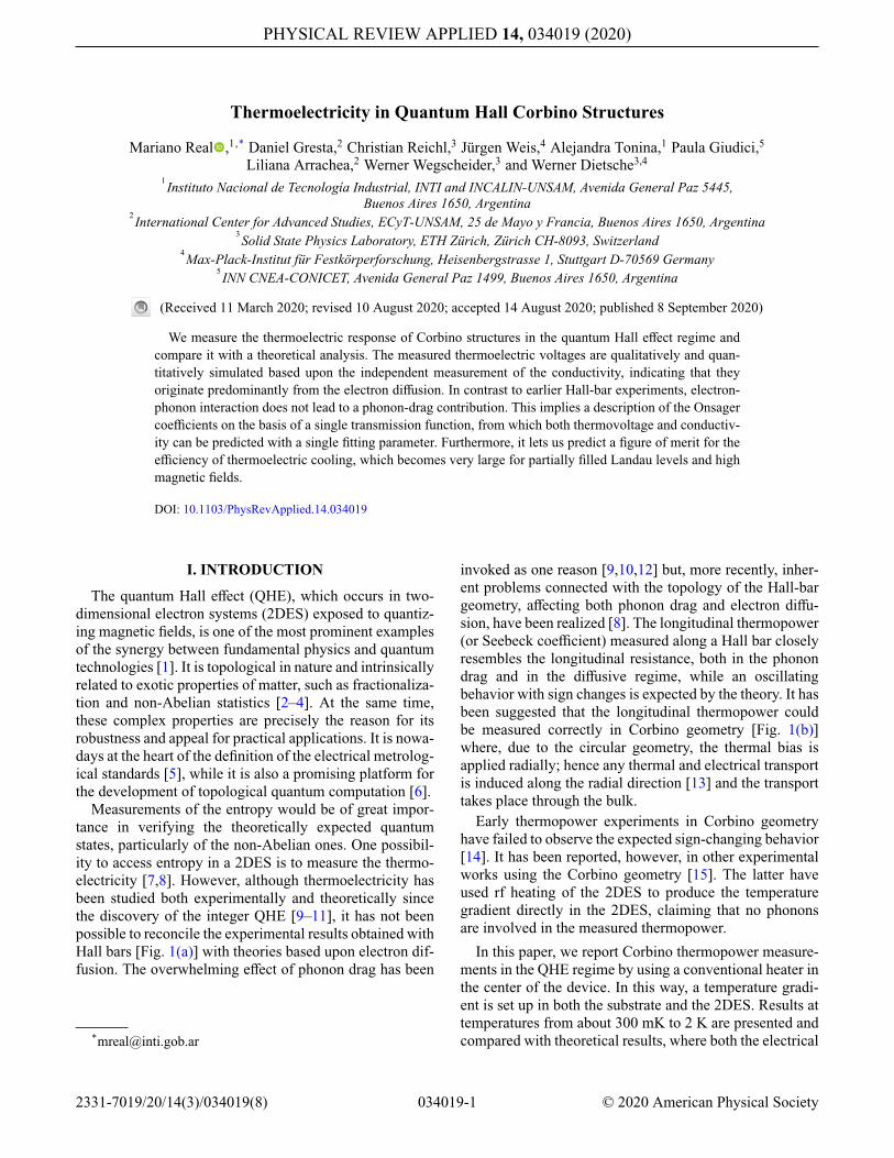
FIG. 1. The two sample designs to investigate thermoelectriceffects: (a) the Hall bar; (b) the Corbino. The dark-gray areasare the 2DES. The hot and the cold contacts for measuring thethermovoltage are at the two ends of the rectangular-shaped Hallbar. For the Corbino, the hot contact is in the center of the 2DES,which is surrounded by the cold contact.
conductance and the thermopower are modeled based uponthe same transmission function. A very good agreementover our range of magnetic fields and temperatures isfound. This demonstrates that the substantial disagreementthat is typical for Hall bars can be removed by using theCorbino topology. In contrast to Hall-bar studies, it is notnecessary to consider phonon drag in the theory.
II. EXPERIMENTAL DETAILS
A. Setup
Our setup is sketched in Fig. 2. An Au-Pd thin-filmheater is inserted in the center of the Corbino samples andheated with an ac current with a frequency f of a few hertz,producing a temperature oscillation of 2 f . In this way, aradial thermal gradient is induced between the center andthe external edge of the sample, which is assumed to beclose to the temperature T of the bath. The device used hereconsists of five concentric ohmic contact rings with diam-eters ranging from 0.4 mm to 3.2 mm, made by alloyingAu-Ge-Ni into the 2DES structure to form four indepen-dent Corbino rings. Under the heater and outside of therings, the 2DES is removed. It is assumed that the localtemperature over the 2DES follows that of the underlyingGaAs substrate. This has already been verified by Chick-ering et al. [16,17] down to much lower temperatures thanthe ones used here. We neglect possible anisotropies in theheat conductivity of the substrate due to the ballistic natureof the phonons, because these become only relevant if thedimensions of the heater and the contacts are much smallerthan the substrate thickness [18].
The four Corbino rings of this device allow us not onlyto measure the thermopower at four different radial dis-tances from the heater but also to determine, in a differentexperiment, the temperatures at the different ring positions.This can be done by using the conductances of the four
(a) (b)
FIG. 2. The scheme of the experimental setup. (a) A crosssection of the sample: note that the heater element is over thesubstrate outside the 2DES. (b) The measurement configurationsfor the conductance and the thermovoltage are shown in magentaand blue, respectively. “LIA” denotes the lock-in amplifier. Thetwo types of experiment are done in separate runs. Only two ofthe four Corbino rings are labeled in the figure.
Corbinos as thermometers. Measurement of the conduc-tance as a function of the bath temperature without anyheat applied is used for calibration. With the heater on, thetemperatures at the different rings can be measured.
As a response to the thermal bias between the center andthe edge of the sample, charges diffuse across the Corbinoring, which is compensated by generating a voltage withfrequency 2 f between the inner and the outer circumfer-ences. The sign and the magnitude of this thermovoltageare determined by the transmission function, as discussedin the theory section. The thermoelectric response in thisdevice is much simpler than the one in the Hall-bar geom-etry, where the transport takes place along longitudinal andtransverse directions with respect to the applied biases. Infact, in the Corbino geometry, the thermovoltage developsalong the direction of the temperature bias.
The samples are grown by molecular-beam epitaxyon GaAs wafers having a single 2DES located in a30-nm-wide quantum well with Si-doped layers on bothsides. Data from two samples from two wafers, A andB, are presented here. Separate test pieces from thesewafers in van der Pauw geometry have mobilities of21 × 106 cm2 V−1 s−1 and 18 × 106 cm2 V−1 s−1 at elec-tron densities of ne = 3.06 × 1011 cm−2 and ne = 2.0 ×1011 cm−2, respectively, measured at 1.3 K in the dark.
The Corbino samples are glued in a standard commer-cial ceramic holder with a gold-plated base and pins anda 3-mm-diameter hole drilled in the middle to reducethermal contact with the samples. The measurements areperformed in vacuum in a 3He cryostat equipped with a
034019-2

THERMOELECTRICITY IN QUANTUM HALL. . . PHYS. REV. APPLIED 14, 034019 (2020)
14-T magnet, with the ability to achieve a base temperatureof 250 mK.
Figure 2 also shows the configurations used for themeasurements of the conductance (magenta) and of thethermovoltage (blue). The conductance G is measuredby applying an ac voltage through a voltage divider andmeasuring the current with an amplifier (IUAmp). Thethermovoltage Vtp is measured in separate runs by passingan ac current of frequency f to the central heater, whichhas a resistance of about 650 �. The thermopower inducedin the sample is measured by using a ×1000 differentialdc voltage amplifier (dc-amp). The input impedance of thisamplifier must be very high, because the internal resistanceof the Corbino device diverges in the quantum Hall states.We use an amplifier with an input impedance of about1 Tω [19]. Very little frequency dependence of the ther-movoltage is found between f = 3 Hz and 100 Hz. Mostmeasurements are done at f = 13.8 Hz. To avoid effectsof time-dependent magnetic fluxes, the waiting time foreach data point is set to a few seconds to guarantee thestabilization of the magnetic fields at a constant value.
B. Thermovoltage measurement
The experimental results for both the thermal voltage(solid blue) and the conductance (solid orange) of sam-ple A are shown in Fig. 3 at a base temperature T of269 mK and an average heater power P of 277 nW. Themagnetic field is swept from 0.3 to 5 T. The conductanceshows the typical Shubnikov–de-Haas (SdH) oscillations,with the spin splitting becoming visible at about 0.9 T andthe conductance minima approaching zero even at fillingfactors less than 20. The thermovoltage Vtp shows numer-ous features. At small magnetic fields, it oscillates witha similar periodicity as the conductance, changing signat both the conductance maxima and minima. At highermagnetic fields, additional features appear in the regionsof the conductance minima, which become very signifi-cant and chaotic at even larger magnetic fields, where theconductance minima are wider. Between the conductanceminima, the thermovoltage Vtp now changes to a sawtooth-like behavior, still changing sign at both the maxima andthe minima of the conductance. Such sign changes havenot been observed in the earlier Hall-bar experiments buthave already been seen in the previous rf-based Corbinoexperiments [15] and have been expected theoretically [8].
We observe the sign-change behavior in a similar wayon several samples with different densities and mobilities.The data for sample B are presented in Fig. 4, showing Vtpmeasured across the three different outer Corbino rings at atemperature of 600 mK. The oscillatory behavior of Vtp isagain clearly visible, as are the large signals in the regionsthat correspond to the conductance minima.
The large signals have not been reported before. Theseare not spurious signals: they are reproducible and they
FIG. 3. The conductance G and thermovoltage Vtp as a func-tion of the magnetic field B for ring 2 in Fig. 2 at temperatureT with power P supplied at the heater. The experimental dataare plotted using solid lines. The theoretical (dashed) plots arebased on the calculation of Eq. (2), with the respective inferredtransmission functions.
persist if the magnetic field is stopped and kept constant orif the sweep direction is reversed. They are definitely ther-mally induced signals and are not produced by an electro-magnetic crosstalk. The large signals vanish by applying adc current on top of a square ac current. This leads to a con-stant heating and thus a vanishing temperature oscillationbut it would leave any suspected crosstalk unchanged. Wewill speculate at the end of this paper about the possibleorigins of the large signals.
FIG. 4. The Vtp response of sample B at different rings at a bathtemperature of 600 mK and a heater power of 213 nW. Rings 2and 3 present a greater temperature gradient and hence a largervoltage response than ring 4.
034019-3
MARIANO REAL et al. PHYS. REV. APPLIED 14, 034019 (2020)
In the following, we concentrate on the analysis of thethermal voltages outside of the SdH minima. We show thatthe magnetic field traces of both Vtp and the conductance Gcan be fitted using only charge diffusion. The same trans-mission function based upon model Landau levels (LLs)is used for calculating both the conductance and the ther-movoltage. The only fitting parameter is the temperaturegradient. The resulting fits are already shown in Fig. 3 asdashed lines.
III. THERMOELECTRIC RESPONSE
A. Onsager coefficients
To describe the thermoelectric transport, we consider theCorbino geometry in Fig. 1(b). The Corbino ring acts as aconductor in the radial direction between the hot and coldreservoirs, with a temperature bias of �T. In the linearresponse, the corresponding charge and heat currents forsmall �T and bias voltage V can be expressed as follows[20]:
(I C/eI Q
)=
(L11 L12L21 L22
) (X1X2
), (1)
where X1 = eV/kBT, X2 = �T/kBT2, and L̂ is the Onsagermatrix. The electrical and thermal conductances are,respectively, G = e2L11/T and κ = DetL̂/
(T2L11
). S =
L12/L11 defines the Seebeck coefficient and � = L21/L11is the Peltier coefficient. For ballistic or diffusive transport,Lij depends only on the quantum dynamics of the electronsin the presence of the magnetic field and the disorder ofthe sample. These are described by a transmission functionT (ε),
Lij = −T∫
dε
h∂f (ε)
∂ε(ε − μ)i+j −2 T (ε), (2)
where f (ε) = 1/(e(ε−μ)/kBT + 1) is the Fermi distributionfunction, μ is the chemical potential, and T is the temper-ature of the electrons. In the presence of disorder and theabsence of electron-electron interactions, T (ε) has origi-nally been calculated by Jonson and Girvin [21]. At hightemperatures, electron-phonon interaction gives rise to anadditional component in the transport coefficients Lij .
B. Conductance and thermovoltage
Our goal is to accurately describe the electronic compo-nent of the Onsager coefficients obtained from the exper-imental data. At first, we measure the conductance G(B)
as a function of the applied magnetic field B. The thermo-voltage Vtp is measured separately and corresponds to the
voltage for which I C = 0 in Eq. (1),
Vtp(B) = −S(B)�TT
. (3)
Here, S(B) is the Seebeck coefficient as a function of themagnetic field, T is the temperature of the bath (cold fingerin our case), and �T is the temperature difference betweenthe two contacts of the Corbino ring under investigation.From the data for G(B), we infer the transmission functionT (ε) entering Eq. (2). Given T (ε), we can evaluate theelectrical component of the other Onsager coefficients; inparticular, L12(B). Through Eq. (3), this leads to a theoret-ical prediction for the behavior of Vtp(B) resulting from theelectrical transport, which can be directly contrasted withthe experimental data.
There are two regimes to be considered for the calcula-tion of T (ε): (i) At low magnetic fields, where the differentLLs are not clearly resolved, we calculate the transmissionfunction using the model introduced in Ref. [8,21]. Thelatter is based on a single-particle picture for the 2DESin the presence of a magnetic field and elastic scatteringintroduced by impurities. (ii) For higher magnetic fields,where the differently filled LLs are clearly distinguishedand are separated by a gap, we use the fact that in the limitof T → 0, Eq. (2) leads to T (μ) ∼ G(μ)/e.
C. Transmission function
1. Low magnetic field
Here, we consider the transmission function [8,21]
T (ε) = ∑n,σ
(n + 1) ω2c
8πhAn,σ (ε)An+1,σ (ε), (4)
where is a geometric factor relating the conductance tothe conductivity, while An,σ (ε) = Im
[Gn,σ (ε)
], in which
Gn,σ (ε) = [ε − εn,σ − �(ε)
]−1 is the Green function cal-culated within the self-consistent Born approximation.εn,σ = �(n + 1/2)ωc ± μBB/2 is the energy of the LLs,including the Zeeman splitting, with ± corresponding,respectively, to σ =↑, ↓. Here, μB is the Born magneton,ωc = eB/m∗ is the cyclotron frequency, m∗ = 0.067me isthe effective mass of the electrons in the structure, andme is the electron mass. The effect of disorder due toimpurities introduces a widening in the LLs, whichis accounted for by the self-energy �(ε) = (ω − εL)/2 −i
√1 − (ε − εL)2/(4 2). Here, εL is the energy of the LL
that is closest to ε. This model has two fitting parameters, and , which we adjust to fit the data of the conductanceG, through Eq. (2). This model fails to reproduce G(B) forhigh magnetic fields (B > 1 T). Thus a different model hasto be used in this regime.
034019-4

THERMOELECTRICITY IN QUANTUM HALL. . . PHYS. REV. APPLIED 14, 034019 (2020)
2. High magnetic field
For higher magnetic fields, satisfying kBT � �ωc, and � �ωc, we can infer the transmission function moreefficiently from the behavior of the conductance within arange of magnetic fields in the neighborhood of a givenfilling fraction ν. Note that in the limit of T → 0, thederivative of the Fermi function entering Eq. (2) has thefollowing behavior: −∂f (ε)/∂ε → δ(ε − μ). Therefore,for low temperatures, such that kBT � �ωc, we have
T (μν) ∼ G(μν)
e, μν = �eB
2m∗ , Bν+1 < B < Bν ,
(5)
where Bν = neh/(eν) is the magnetic field correspondingto the filing fraction ν, while μν is the Fermi energy for therange of B within two consecutive integer filling factors.
IV. RESULTS
A. Thermoelectric response
The results for the conductance and the thermovolt-age are shown in Fig. 3 for a temperature of 269 mK.The experimental data for G and Vtp within the low-magnetic-field regime are shown in the upper panel of thefigure along with the theoretical description based on thetransmission function of Eq. (4).
In the case of a high magnetic field, shown in the lowerpanel, the theoretical description is based on the trans-mission function of Eq. 5. Given T (ε), we calculate theOnsager coefficients of Eq. (2) and the Seebeck coeffi-cient S = L12/L11. The ratio �T/T is adjusted in orderto fit the experimental measurements with Eq. (3). Theestimates for the temperature bias are �T = 1 mK and1.08 mK, for low and high magnetic fields, respectively.Overall—and, in particular, for high magnetic fields—theagreement between experiment and theory is excellentwithin the range of B corresponding to a partially filledLL, for which G �= 0.
Taking into account the good agreement between theexperimental and theoretical estimates of the tempera-ture difference �T found in the analysis of the data ofFig. 3, we now analyze the relation between the electri-cal power supplied at the heater and �T. In Fig. 5, weshow experimental data for the thermovoltage at a fixedtemperature and different heater powers. We assume a lin-ear dependence between these quantities. Therefore, we fitthe experimental data with the same Seebeck coefficientS(B) calculated for Fig. 3 and the following dependenceof the temperature difference as a function of the power:�T(P′) = P′/P 1.08 mK, where P′ is the power corre-sponding to the experimental data and P is the power usedin the data of Fig. 3. We see very good agreement betweenthe theoretical prediction and the experimental data. InFig. 6, we discuss the evolution of Vtp as the temperature
FIG. 5. The thermovoltage Vtp for a fixed temperature anddifferent powers P′ applied at the heater, assuming �T(P′) =P′/P1.08 mK. P and other details are the same as in Fig. 3.
grows, focusing on the high-magnetic-field region. Theexperimental data are presented along with the theoreti-cal prediction obtained by following the same procedureas in the previous figures and taking into account the lineardependence of �T with P as explained in Fig. 5. Over-all, the agreement between the theoretical predictions andthe experimental data for magnetic fields corresponding topartially filled LLs over a wide range of temperatures isvery good, improving as the temperature decreases.
B. Theoretical estimate of �T
From the behavior of the conductance, we can inferthe transmission function T (ε) as explained before, fromwhich we can calculate the Onsager coefficients Lij . Werecall that the thermovoltage is defined in Eq. (3). Giventhe calculation of S(B), we need to adjust the parameter�T/T in order to fit the data. Since the latter enters as theslope in the linear function V(S), we analyze plots of themeasured Vtp versus the calculated S for values of B withinwhich the LLs are partially filled and we fit a linear func-tion to obtain the slope. Examples are shown in Fig. 7 fortwo different LLs, with bath temperature T = 269 mK anda power of 277 nW.
The corresponding fits cast �T = (1.01 ± 0.06) mK inthe region from B = 2.21 T to 2.46 T (upper panel) and�T = (1.33 ± 0.06) mK in the region from B = 2.625 Tto 3 T (lower panel), with uncertainties corresponding toa 95% confidence probability. Note also that the intercept,which is taken as a free parameter of the regression, is zerowithin the error in both cases.
The data for the other sample measured at 600 mK,shown in Fig. 4, can be analyzed similarly for severalof the rings. For ring 2, we obtain �T = (60 ± 3) μK,while for ring 3 we obtain (�T = (110 ± 10) μK and forring 4 �T = (74 ± 50) μK. These values are considerablylower those of sample A measured at 269 mK. The rea-son for this is that the thermal conductivity of the substrate
034019-5

MARIANO REAL et al. PHYS. REV. APPLIED 14, 034019 (2020)
FIG. 6. The thermovoltage Vtp, as function of the magneticfield for different temperatures. In the case of 269–680 mK, apower of 277 nW is used, while for 1.37–1.5 K, the heater poweris 433 nW. The other details are the same as in previous figures.The scale for Vtp is the same in all panels.
increases with T3 and at 600 mK the temperature gradi-ent will be nearly 10 times smaller and, correspondingly,a much smaller temperature difference is expected at thehigher temperature.
C. Experimental estimate of �T
The exact determination of �T in a Corbino device turnsout to be challenging. The reason for this is that the highphonon-heat conductivity in the GaAs substrate leads tosmall temperature gradients between the center and theedges of the sample. One consequence is that the ther-mal resistance from the sample to the ceramic carrier canno longer be neglected. Using the temperature-dependentconductances of the Corbino rings as thermometers, weare nevertheless able to make estimates. The innermostand the outermost rings in Fig. 2 are used for this mea-surement. The conductance minimum at filling factor 9in Fig. 3 is used because it shows a pronounced temper-ature dependence. The actual temperatures at these ringsare found by comparing the respective conductances with
FIG. 7. The measured Vtp signal versus the calculated −Swithin the range of fields B = 2.21–2.46 T (upper panel) and B =2.625–3 T (lower panel). The slope of this relation is �T/T. 95%Prediction Intervals (pred. inter.) indicates the range correspond-ing to 95% of reliability of the mean squares regression used inthe linear fit.
the heater on and off. The temperature rise at both ringscould be close to 50 mK with the cryostat at 269 mKand heater powers reaching 300 nW. The temperature dif-ference between the two rings is found to be less than 9mK at the highest power. This value is only an estimatebecause the precision and the reproducibility of the cali-bration procedure is limited by the temperature control ofthe cryostat.
The determination of �T could be improved by thinningthe sample and thereby decreasing its thermal conduc-tance. If this is done for several samples, it can be shownthat the thermovoltage data as a function of the mag-netic field becomes erratic. We suspect that the thinningleads to inhomogeneities in the 2DES, making the Vtpmeasurements useless. Doping of the substrate with Crwould be another way to decrease the thermal conductiv-ity.
Alternatively, we estimate the temperature profile usingliterature values of the thermal conductivity κ . From Ref.[16], we deduce a κ of about 0.01 W/mK at 300 mK. Usingthe simulation software COMSOL, a temperature differenceof 2.5 mK between the center and edge of our sample isfound from the heat-flow equation. This would lead to atemperature difference across ring 2 of about 1 mK, in goodagreement with the used fit values.
034019-6

THERMOELECTRICITY IN QUANTUM HALL. . . PHYS. REV. APPLIED 14, 034019 (2020)
V. THERMOELECTRIC PERFORMANCE
The quality of the thermoelectric performance, i.e., theefficiency (for a heat engine) or the coefficient of perfor-mance (for a refrigerator), has been the subject of greatinterest in recent years, particularly in the context ofthe ballistic transport along edge channels and nanosizeddevices [22–30]. We find that the theoretical performanceof a Corbino device in the quantum Hall regime is sur-prisingly large, being comparable to the highest predictedvalues in devices based upon ballistic transport. The per-formance is parameterized as the figure of merit [20],ZT = L2
21/DetL̂, or S2 times the ratio of the electric andthermal conductivity.
The optimal Carnot efficiency or coefficient of perfor-mance is achieved for ZT → ∞.
The highest reported values in real, usually semi-conducting, materials are between 1 ≤ ZT ≤ 2.7 [20,31],while optimistic theoretical predictions in the ballisticedge-channel regime are ZT ∼ 4 [32] or lower. In Fig.8, we show the transmission function T (ε) used for theCorbino in this work to fit the experimental data of Fig.3 within the high-magnetic-field regime. We see that thesequence of sharp features at the LL realizes energy filters,leading to large values of ZT ∼ 6. Thus, diffusive transportacross the bulk of a Corbino device has a potentially higherperformance than the envisioned edge-channel devices.Figure 8 suggests that even higher ZT values should bepossible at lower temperatures. We stress that this analysisis based on the assumption that the main contribution tothe thermoelectric and thermal transport is due to the elec-trons. Phononic thermal transport in the substrate wouldtend to decrease the performance but would die out ateven lower temperatures with T3, while the figure of meritwould probably increase. Thus one could envision that theCorbino device could be used as a thermoelectric cooler in
FIG. 8. Bottom: the transmission function T (ε). Top: theelectron contribution to the figure of merit ZT.
the low-millikelvin regime for specific purposes. Replace-ment of the heater by the object to be cooled could alreadybe sufficient to form a realistic device.
VI. CONCLUSIONS
We analyze the thermoelectric response of a Corbinostructure in the quantum Hall regime. For partially filledLLs, we find excellent agreement between the experi-mental data and the theoretical description, based on theassumption that the thermoelectric response originates inthe diffusion of electrons while electron-phonon drag doesnot influence the thermovoltage in the temperature rangefrom 300 mK to 2 K. Clearly, the electron-phonon inter-action does not vanish in the Corbino geometry but thetransfer of momentum from the phonons to the electronsdoes not lead to a measurable voltage. Actually, it hasalready been noted a long time ago that the contributionof the phonon-drag mechanism to the thermoelectric coef-ficient L12 should be zero in the heat-flow direction [10],which is, simply put, a consequence of the Lorentz force.It appears that only in Corbino devices is the vanishingcontribution of phonon drag reflected in the thermovolt-age measurement. Within the diffusive model applicablefor Corbino rings, we are able to accurately fit the temper-ature difference, producing the thermopower based on themeasured conductance traces, and we find it to be consis-tent with both our experimental temperature estimates andthat derived from independent thermal-conductivity data.The calculated figure of merit ZT is remarkably high forhigh magnetic fields, indicating that this system is verypromising as a low-temperature cooling device or a heatengine.
Future work needs to clarify the origin of the large volt-age signals at the conductance minima, i.e., in the quan-tized state, where both the electric conductance and thethermal conductance values of the Onsager equation van-ish. Also, different mechanisms might be relevant in theseregimes, such as temperature-driven magnetic flux [13] ortemperature-dependent contact potentials that cannot equi-librate in the conductance minima [33]. Another importantdirection would be the extension of the experiment tolower temperatures. Determination of the entropy in thefractional quantum Hall regime could answer some urgentquestions about the entropy of the suspected non-Abelianstates.
ACKNOWLEDGMENTS
We thank Klaus von Klitzing for his constant inter-est and support, Achim Güth and Marion Hagel for thewafer lithography, and Mirko Lupatini, Luca Alt, andSimon Parolo for help with the experiments. Peter Märkiprovided the amplifiers used in this work, while Lars Tie-mann contributed the measurement software NANOMEAS.We received useful comments on the manuscript from
034019-7

MARIANO REAL et al. PHYS. REV. APPLIED 14, 034019 (2020)
Peter Samuelsson. We acknowledge support from theInstituto Nacional de Tecnología Industrial (INTI) andthe National Scientific and Technical Research Council(Consejo Nacional de Investigaciones Cientficas y Técni-cas, CONICET), Argentina. We are sponsored by GrantNo. PIP-RD 20141216-4905 of CONICET, Grants No.PICT-2017- 2726 and No. PICT-2018 from Argentina,the Swiss National Foundation (Schweizerischer Nation-alfonds) National Center of Competence in Research(NCCR) “Quantum Science and Technology,” as well asthe Alexander von Humboldt Foundation, Germany.
[1] K. v. Klitzing, G. Dorda, and M. Pepper, New Method forHigh-Accuracy Determination of the Fine-Structure Con-stant Based on Quantized Hall Resistance, Phys. Rev. Lett.45, 494 (1980).
[2] D. C. Tsui, H. L. Stormer, and A. C. Gossard, Two-Dimensional Magnetotransport in the Extreme QuantumLimit, Phys. Rev. Lett. 48, 1559 (1982).
[3] R. B. Laughlin, Anomalous Quantum Hall Effect: AnIncompressible Quantum Fluid with Fractionally ChargedExcitations, Phys. Rev. Lett. 50, 1395 (1983).
[4] J. K. Jain, Microscopic theory of the fractional quantumHall effect, Adv. Phys. 41, 105 (1992).
[5] T. Gerster, A. Müller, L. Freise, D. Reifert, D. Maradan, P.Hinze, T. Weimann, H. Marx, K. Pierz, H. W. Schumacher,F. Hohls, and N. Ubbelohde, Robust formation of quantumdots in GaAs/AlGaAs heterostructures for single-electronmetrology, Metrologia 56, 014002 (2018).
[6] C. Nayak, S. H. Simon, A. Stern, M. Freedman, and S.Das Sarma, Non-Abelian anyons and topological quantumcomputation, Rev. Mod. Phys. 80, 1083 (2008).
[7] K. Yang and B. I. Halperin, Thermopower as a possibleprobe of non-Abelian quasiparticle statistics in fractionalquantum Hall liquids, Phys. Rev. B 79, 115317 (2009).
[8] Y. Barlas and K. Yang, Thermopower of quantum Hallstates in Corbino geometry as a measure of quasiparticleentropy, Phys. Rev. B 85, 195107 (2012).
[9] R. Fletcher, M. D’Iorio, W. T. Moore, and R. Stoner, Asearch for trends in the thermopower of GaAs-Ga1−xAlxAsheterojunctions, J. Phys. C 21, 2681 (1988).
[10] T. M. Fromhold, P. N. Butcher, G. Qin, B. G. Mulimani, J.P. Oxley, and B. L. Gallagher, Phonon-drag magnetother-mopower oscillations in GaAs/AsxGa1 − x As heterojunc-tions, Phys. Rev. B 48, 5326 (1993).
[11] B. Tieke, U. Zeitler, R. Fletcher, S. A. J. Wiegers, A.K. Geim, J. C. Maan, and M. Henini, Even-DenominatorFilling Factors in the Thermoelectric Power of a Two-Dimensional Electron Gas, Phys. Rev. Lett. 76, 3630(1996).
[12] S. Maximov, M. Gbordzoe, H. Buhmann, L. W. Molenkamp,and D. Reuter, Low-field diffusion magnetothermopower ofa high-mobility two-dimensional electron gas, Phys. Rev. B70, 121308 (2004).
[13] V. T. Dolgopolov, A. A. Shashkin, N. B. Zhitenev, S. I.Dorozhkin, and K. von Klitzing, Quantum Hall effect in theabsence of edge currents, Phys. Rev. B 46, 12560 (1992).
[14] H. van Zalinge, R. W. van der Heijden, and J. H. Wolter,Anisotropic Corbino magnetothermopower in a quantumHall system, Phys. Rev. B 67, 165311 (2003).
[15] S. Kobayakawa, A. Endo, and Y. Iye, Diffusion ther-mopower of quantum Hall states measured in Corbinogeometry, J. Phys. Soc. Jpn. 82, 053702 (2013).
[16] W. E. Chickering, J. P. Eisenstein, L. N. Pfeiffer, and K. W.West, Thermopower of two-dimensional electrons at fillingfactors ν = 3/2 and 5/2, Phys. Rev. B 81, 245319 (2010).
[17] W. E. Chickering, J. P. Eisenstein, L. N. Pfeiffer, and K. W.West, Thermoelectric response of fractional quantized Halland reentrant insulating states in the N = 1 Landau level,Phys. Rev. B 87, 075302 (2013).
[18] J. P. Wolfe, Imaging Phonons: Acoustic Wave Propagationin Solids (Cambridge University Press, Cambridge, 1998).
[19] P. Märki, B. A. Braem, and T. Ihn, Temperature-stabilizeddifferential amplifier for low-noise dc measurements, Rev.Sci. Instrum. 88, 085106 (2017).
[20] G. Benenti, G. Casati, K. Saito, and R. S. Whitney, Funda-mental aspects of steady-state conversion of heat to work atthe nanoscale, Phys. Rep. 694, 1 (2017).
[21] M. Jonson and S. M. Girvin, Thermoelectric effect in aweakly disordered inversion layer subject to a quantizingmagnetic field, Phys. Rev. B 29, 1939 (1984).
[22] R. Sánchez, B. Sothmann, and A. N. Jordan, Chiral Ther-moelectrics with Quantum Hall Edge States, Phys. Rev.Lett. 114, 146801 (2015).
[23] S. Kheradsoud, N. Dashti, M. Misiorny, P. P. Potts, J.Splettstoesser, and P. Samuelsson, Power, efficiency andfluctuations in a quantum point contact as steady-statethermoelectric heat engine, Entropy 21, 777 (2019).
[24] D. Gresta, M. Real, and L. Arrachea, Optimal Thermoelec-tricity with Quantum Spin Hall Edge States, Phys. Rev.Lett. 123, 186801 (2019).
[25] P. P. Hofer and B. Sothmann, Quantum heat engines basedon electronic Mach-Zehnder interferometers, Phys. Rev. B91, 195406 (2015).
[26] P. Samuelsson, S. Kheradsoud, and B. Sothmann, OptimalQuantum Interference Thermoelectric Heat Engine withEdge States, Phys. Rev. Lett. 118, 256801 (2017).
[27] L. Vannucci, F. Ronetti, G. Dolcetto, M. Carrega, and M.Sassetti, Interference-induced thermoelectric switching andheat rectification in quantum Hall junctions, Phys. Rev. B92, 075446 (2015).
[28] P. Roura-Bas, L. Arrachea, and E. Fradkin, Enhanced ther-moelectric response in the fractional quantum Hall effect,Phys. Rev. B 97, 081104(R) (2018).
[29] F. Giazotto, F. Taddei, M. Governale, R. Fazio, and F.Beltram, Landau cooling in metal? Semiconductor nanos-tructures, New J. Phys. 9, 439 (2007).
[30] L. Fu, Cryogenic Cooling and Power Generation UsingQuantum Hall Systems, arXiv:1909.09506.
[31] J. He and T. M. Tritt, Advances in thermoelectric materialsresearch: Looking back and moving forward, Science 357,6358 (2017).
[32] A. Ozaeta, P. Virtanen, F. S. Bergeret, and T. T.Heikkilä, Predicted Very Large Thermoelectric Effect inFerromagnet-Superconductor Junctions in the Presence ofa Spin-Splitting Magnetic Field, Phys. Rev. Lett. 112,057001 (2014).
[33] K. von Klitzing, Private Communication.
034019-8