physical systems under uncertainty: systematic, extensible
TRANSCRIPT
D2.3 Version1.0 ConfidentialityLevel:PU
27.10.2017 U-Test Page1of26
Testing Cyber-Physical Systems under Uncertainty: Systematic, Extensible, and Configurable Model-based and Search-based Testing Methodologies
D 2.3 - Report on Uncertainty Modelling Framework V.3
ProjectAcronym U-Test GrantAgreementNumber H2020-ICT-2014-1.645463
DocumentVersion 1.0 Date 2017-10-27 DeliverableNo. 2.3
ContactPerson PhuHongNguyen Organisation SimulaResearchLaboratory
Phone +4790025581 E-Mail [email protected]
D2.3 Version1.0 ConfidentialityLevel:PU
27.10.2017 U-Test Page2of26
DocumentVersionHistory
VersionNo. Date Change Author(s)
0.1 2017-01-19 Initialdocumentoutline PhuNguyen
0.2 2017-03-08 Detaileddocumentoutline PhuNguyen
0.3 2017-04-17 Section1 PhuNguyen
0.4 2017-04-18 NewSection3.3 LucaBerardinelli
0.5 2017-04-19 Section2.1 SRL
0.6 2017-04-21 Section2.2,Section3.1 SRL
0.7 2017-05-05 NewTUWSections LucaBerardinelli
0.8 2017-05-05 SectionsrelatedtoApplicationlevel FF
0.9 2017-05-08 Integration SRL
0.9Inter 2017-05-30 Intermediateversion SRL
0.95 2017-09-06 Arevisedversionwithoutthemodelsofpilots SRL
0.96 2017-10-19 UpdatedbySRLandTUW SRL,TUW
0.97 2017-10-20 LastupdatesfromFF FF
0.98 2017-10-26 Revisedaccordingtothereviews SRL,TUW,FF
1.0 2017-10-27 Finalversion SRL,TUW,FF
Contributors
Name Partner PartAffected Date
ShaukatAli SRL Sections2.1,3.1,4.1,5.1
ManZhang SRL Sections2.1,3.1,4.1,5.1
TaoYue SRL Sections2.1,3.1,4.1,5.1
PhuHongNguyen SRL All
Marc-FlorianWendland FF Sections3.2,4.2,5.2
LucaBerardinelli TUW Sections3.3,4.3,5.3
Reviewers
Name Partner PartAffected Date
FabienPeureux EGM All
CésarCuevas IKL All
D2.3 Version1.0 ConfidentialityLevel:PU
27.10.2017 U-Test Page3of26
ExecutiveSummaryTheUncertaintyModellingFramework(UMF)providesasystematicwayforstandard-basedholistic modelling as a Unified Modelling Language (UML) profile for the specification ofuncertaintyconceptsinCyber-PhysicalSystems(CPS).FollowinganAgile-likeapproach,thisdeliverablereportsonthethirdversionof theUMF(UMFV3),which isanupgradeonthetwopreviousversions(UMFV1andUMFV2,reportedinthedeliverablesD2.1[3]andD2.2[4]). Specifically, the UMF V3 improves from the UMF V2 by 1) improving the modellingprofiles;and2)finalizingthemodellingmethodologysuchastheguidelinesforapplyingtheUMLTestingProfile(UTP),modellingindeterminacysources,integratingformalfitnessfactorprovider, and extending library for supporting rule-based evolution strategy. We haveshowedhowtheUMFV3isanupgradeonV2foruncertaintymodellingattheapplication,infrastructure,andintegrationlevelsofCPS.
Keywords:Cyber-PhysicalSystems,UncertaintyModelling,ModellingFramework,UML,UTP
D2.3 Version1.0 ConfidentialityLevel:PU
27.10.2017 U-Test Page4of26
TableofContentsExecutiveSummary...................................................................................................................3Abbreviations............................................................................................................................51 Introduction........................................................................................................................6
1.1 U-TestWorkflow..........................................................................................................61.2 ObjectivesoftheDeliverable......................................................................................71.3 StructureoftheDeliverable........................................................................................7
2 UncertaintyModellingFrameworkV3...............................................................................82.1 AnoverviewoftheUMF..............................................................................................82.2 AnOverviewoftheUpdatesintheUMFV3................................................................8
3 UpdatesonUMLUncertaintyProfile..................................................................................93.1 Core(IntegrationLevel)Profile...................................................................................93.2 ApplicationLevelProfile............................................................................................113.3 InfrastructureProfile.................................................................................................11
3.3.1 TheInfrastructureUncertaintyProfile...............................................................123.3.2 TheInfrastructureCPSProfile............................................................................14
4 UpdatesonModellingMethodology................................................................................184.1 UpdatesintheMethodologyattheIntegrationLevel..............................................184.2 UpdatesofthemodellingmethodologyattheApplicationlevel..............................21
4.2.1 Pilotmodellingprocess.......................................................................................214.2.2 Uncertaintymodelling........................................................................................224.2.3 Deploymentmodelling.......................................................................................22
4.3 UpdatesoftheInfrastructurelevelmodellingmethodology....................................244.4 Test-ReadyModelsforPilots.....................................................................................24
5 Summary...........................................................................................................................245.1 UMFforIntegrationLevel.........................................................................................255.2 UMFforApplicationLevel.........................................................................................255.3 UMFforInfrastructureLevel.....................................................................................25
6 Bibliography......................................................................................................................26
D2.3 Version1.0 ConfidentialityLevel:PU
27.10.2017 U-Test Page5of26
Abbreviations
CPS Cyber-PhysicalSystem
Dx Deliverablenumberx
EGM EasyGlobalMarket
FPX FuturePositionX
FF FraunhoferFOKUS
IEEE InstituteofElectricalandElectronicsEngineers
IoT InternetofThings
IKL Ikerlan
MARTE ModellingandAnalysisofReal-TimeandEmbeddedSystems
MBT Model-BasedTesting
Mx Milestone
NMT NordicMedtest
OCL ObjectConstraintLanguage
SBSE Search-BasedSoftwareEngineering
SRL SimulaResearchLaboratory
SUT SystemUnderTest
TR TechnicalReport
TUW TechnischeUniversitätWien
T4UME ToolforUncertaintyModellingandEvaluation
U-Taxonomy UncertaintyTaxonomy
UHS ULMAHandlingSystems
UME UncertaintyModellingandEvaluation
UMF UncertaintyModellingFramework
UTF UncertaintyTestingFramework
UTP UMLTestingProfile
UUP UMLUncertaintyProfile
WP WorkPackage
D2.3 Version1.0 ConfidentialityLevel:PU
27.10.2017 U-Test Page6of26
1 IntroductionThis document presents the work done for the WP2’s Task 2.3 in developing the thirdversion of the Uncertainty Modelling Framework (UMF V3). The UMF provides amethodology to create and specify test-ready models based on existing modelling andtestingstandards.ThemodelsarebasedontheU-Testspecificuncertaintyprofileprovidingthe relevant concepts todescribeuncertaintyat theApplication level, Infrastructure level,and Integration level of CPS. This report presents theUMFV3, achieved through iterativeimprovementsovertheUMFV2reportedinD2.2[4].ThisisthefinaldeliverableoftheWP2,whichdocumentsthecompleteUMFV3.
InSection1.1,werevisitthepositionofUMFanditsV3inthewholeU-Testworkflow.ThespecificobjectivesofthisdeliverablearepresentedinSection1.2.Then,wegiveinSection1.3anoverviewofthemaincontentofthisdocument.
1.1 U-TestWorkflow
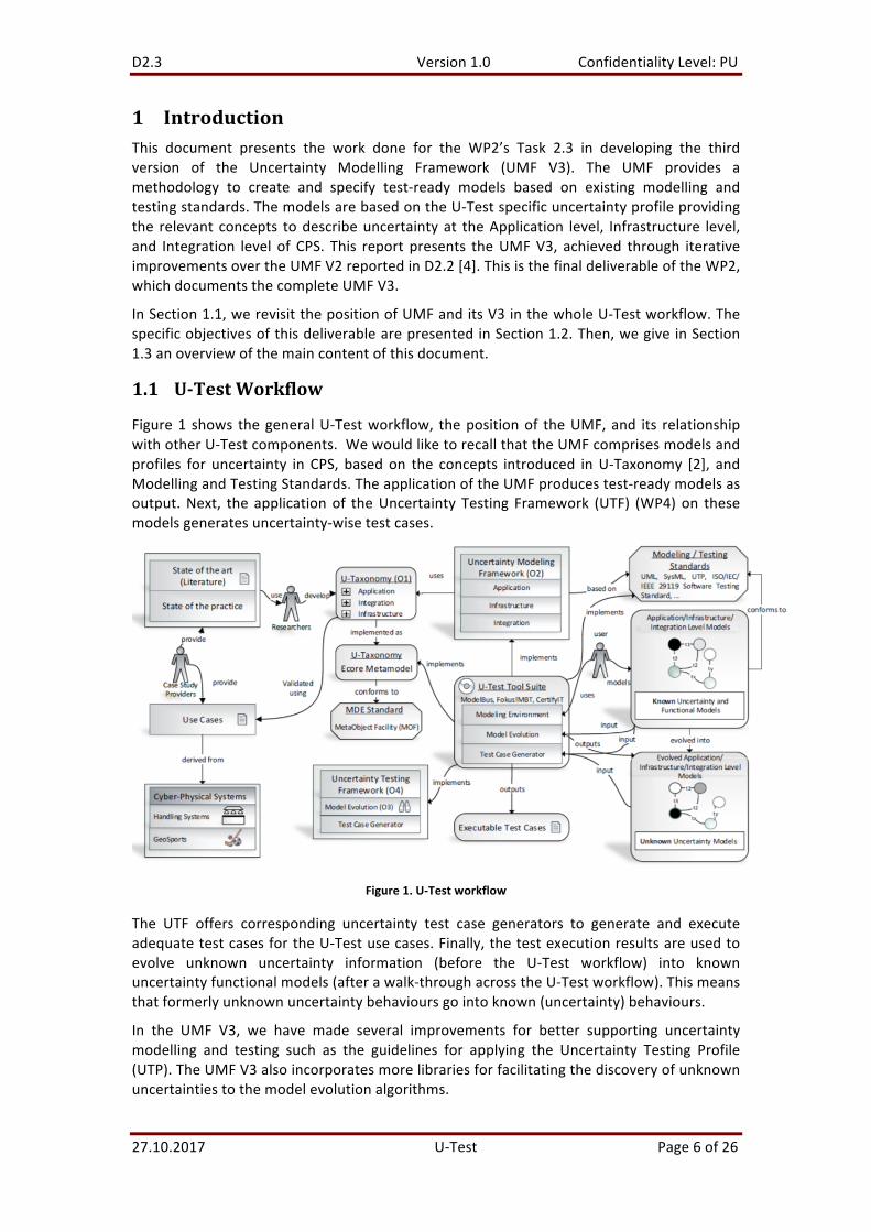
Figure1 shows thegeneralU-Testworkflow, thepositionof theUMF,and its relationshipwithotherU-Testcomponents.WewouldliketorecallthattheUMFcomprisesmodelsandprofiles for uncertainty in CPS, basedon the concepts introduced inU-Taxonomy [2], andModellingandTestingStandards.TheapplicationoftheUMFproducestest-readymodelsasoutput.Next, the applicationof theUncertainty Testing Framework (UTF) (WP4)on thesemodelsgeneratesuncertainty-wisetestcases.
Figure1.U-Testworkflow
The UTF offers corresponding uncertainty test case generators to generate and executeadequatetestcasesfortheU-Testusecases.Finally,thetestexecutionresultsareusedtoevolve unknown uncertainty information (before the U-Test workflow) into knownuncertaintyfunctionalmodels(afterawalk-throughacrosstheU-Testworkflow).Thismeansthatformerlyunknownuncertaintybehavioursgointoknown(uncertainty)behaviours.
In the UMF V3, we have made several improvements for better supporting uncertaintymodelling and testing such as the guidelines for applying the Uncertainty Testing Profile(UTP).TheUMFV3alsoincorporatesmorelibrariesforfacilitatingthediscoveryofunknownuncertaintiestothemodelevolutionalgorithms.

D2.3 Version1.0 ConfidentialityLevel:PU
27.10.2017 U-Test Page7of26
1.2 ObjectivesoftheDeliverable
The main objectives of this deliverable are two-fold. On one hand, we report theimprovementsthatwehavemadefromtheUMFV2intermsofmodellingmethodologyandsupportinglibraries.TheseimprovementsresultinthenewversionofUMF,namelyUMFV3.Ontheotherhand,weshowinthecompanionD2.4[5]howwehaveusedthislatestversionof UMF to completely model all the use cases of the two pilot systems. The test-readymodels specify 100% of the Geo Sports and Warehouse Management System (WMS)scenarios,aswellastheusecasesdescribedforthem[1].
1.3 StructureoftheDeliverable
Theremainderofthisdocumentisstructuredasfollows:Section2presentsanoverviewoftheUMF.WebrieflydescribetheupdatesintheUMFV3,comparedtotheUMFV2thatwehavereportedintheD2.2[4].Then,wepresentinSection3thedetailedupdatesintheUMLUncertainty Profile (UUP) of the UMF V3. Section 4 shows the updates of modellingmethodology for supporting uncertainty modelling at three CPS levels, i.e., application,infrastructure, and integration. Section 5 concludes this document by summarizing theachievementsoftheUMFV3.
D2.3 Version1.0 ConfidentialityLevel:PU
27.10.2017 U-Test Page8of26
2 UncertaintyModellingFrameworkV3Inthissection,wepresentanoverviewoftheUMFV3anditsupdatesbasedontheUMFV2reported in theD2.2 [4].Specifically,werecall inSection2.1 thearchitecturaloverviewofthe UMF. Then, in Section 2.2, we present an overview of the updates to the UMLUncertaintyProfile,ModelLibrariesandModellingMethodologycomparedtotheUMFV2.
2.1 AnoverviewoftheUMF
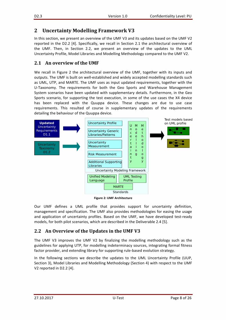
We recall in Figure 2 the architectural overviewof theUMF, togetherwith its inputs andoutputs.TheUMFisbuiltonwell-establishedandwidelyacceptedmodellingstandardssuchasUML,UTP,andMARTE.TheUMFusesasinputupdatedrequirements,togetherwiththeU-Taxonomy. The requirements for both the Geo Sports and Warehouse ManagementSystemscenarioshavebeenupdatedwithsupplementarydetails.Furthermore, in theGeoSports scenario, for supporting the testexecution, in someof theusecases theX4devicehas been replaced with the Quuppa device. These changes are due to use caserequirements. This resulted of course in supplementary updates of the requirementsdetailingthebehaviouroftheQuuppadevice.
Figure2:UMFArchitecture
Our UMF defines a UML profile that provides support for uncertainty definition,managementandspecification.TheUMFalsoprovidesmethodologiesforeasingtheusageand application of uncertainty profiles. Based on theUMF,we have developed test-readymodels,forbothpilotscenarios,whicharedescribedintheDeliverable2.4[5].
2.2 AnOverviewoftheUpdatesintheUMFV3
The UMF V3 improves the UMF V2 by finalizing the modelling methodology such as theguidelinesforapplyingUTP,formodellingindeterminacysources,integratingformalfitnessfactorprovider,andextendinglibraryforsupportingrule-basedevolutionstrategy.
In the following sections we describe the updates to the UML Uncertainty Profile (UUP,Section3),ModelLibrariesandModellingMethodology(Section4)withrespecttotheUMFV2reportedinD2.2[4].
D2.3 Version1.0 ConfidentialityLevel:PU
27.10.2017 U-Test Page9of26
3 UpdatesonUMLUncertaintyProfileThe U-Test UML Uncertainty Profile (UUP) is divided into (1) Core Profile, (2) ApplicationLevelProfile,and(3)InfrastructureLevelProfile.
3.1 Core(IntegrationLevel)Profile
This section only highlights the updates as compared to D2.2 [4] to avoid unnecessaryrepetition.Morespecifically,thereareafewupdatesinthecoreprofileformodellingBeliefandUncertainty.
SincewefocusontestingaCPSinthepresenceofenvironmentaluncertainties,weneedtointroduceuncertaintiesinthephysicalenvironmentthatleadtotheuncertainbehaviouroftheCPS.Toachievethis,wehavefurtherextendedtheindeterminacysourceintheprofiletoenablethemodellingofindeterminacysources.
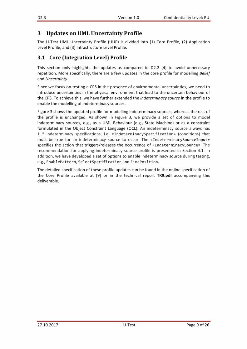
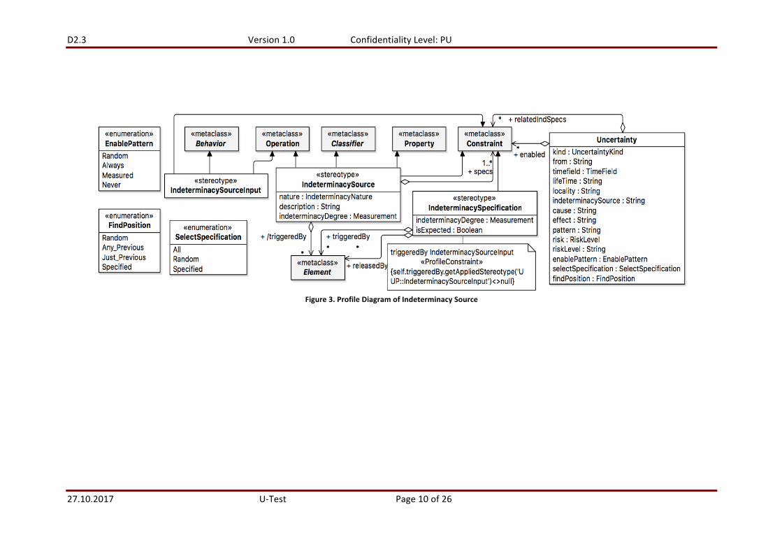
Figure3showstheupdatedprofileformodellingindeterminacysources,whereastherestofthe profile is unchanged. As shown in Figure 3, we provide a set of options to modelindeterminacy sources, e.g., as a UML Behaviour (e.g., StateMachine) or as a constraintformulated in theObject Constraint Language (OCL). An indeterminacy source always has1..* indeterminacy specifications, i.e. «IndeterminacySpecification» (conditions) thatmust be true for an indeterminacy source to occur. The «IndeterminacySourceInput»specifies theactionthat triggers/releases theoccurrenceof«IndeterminacySource».Therecommendation for applying indeterminacy source profile is presented in Section 4.1. Inaddition,wehavedevelopedasetofoptionstoenableindeterminacysourceduringtesting,e.g.,EnablePattern,SelectSpecificationandFindPosition.
Thedetailedspecificationoftheseprofileupdatescanbefoundintheonlinespecificationofthe Core Profile available at [9] or in the technical report TR9.pdf accompanying thisdeliverable.
D2.3 Version1.0 ConfidentialityLevel:PU
27.10.2017 U-Test Page10of26
Figure3.ProfileDiagramofIndeterminacySource
D2.3 Version1.0 ConfidentialityLevel:PU
27.10.2017 U-Test Page11of26
3.2 ApplicationLevelProfile
NochangeswithrespecttoD2.2[4].
3.3 InfrastructureProfile
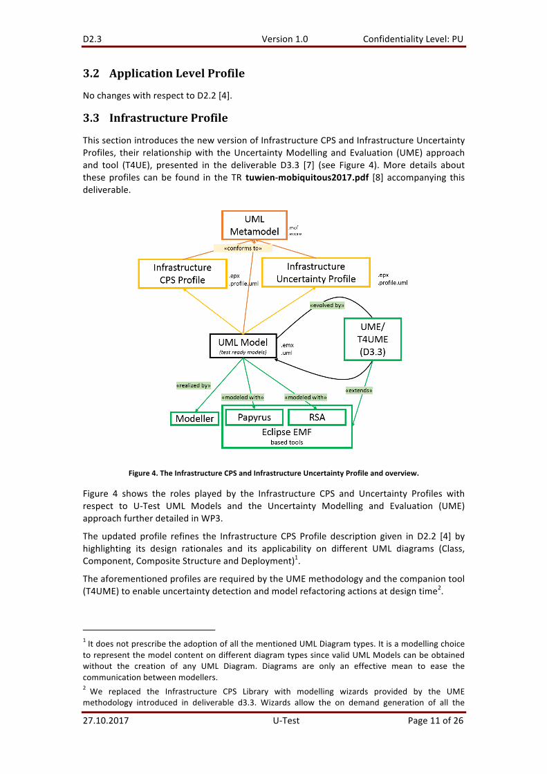
ThissectionintroducesthenewversionofInfrastructureCPSandInfrastructureUncertaintyProfiles, their relationshipwith theUncertaintyModelling andEvaluation (UME) approachand tool (T4UE), presented in the deliverable D3.3 [7] (see Figure 4).More details abouttheseprofiles canbe found in the TR tuwien-mobiquitous2017.pdf [8] accompanying thisdeliverable.
Figure4.TheInfrastructureCPSandInfrastructureUncertaintyProfileandoverview.
Figure 4 shows the roles played by the Infrastructure CPS and Uncertainty Profiles withrespect to U-Test UML Models and the Uncertainty Modelling and Evaluation (UME)approachfurtherdetailedinWP3.
The updated profile refines the Infrastructure CPS Profile description given in D2.2 [4] byhighlighting its design rationales and its applicability on different UML diagrams (Class,Component,CompositeStructureandDeployment)1.
TheaforementionedprofilesarerequiredbytheUMEmethodologyandthecompaniontool(T4UME)toenableuncertaintydetectionandmodelrefactoringactionsatdesigntime2.
1ItdoesnotprescribetheadoptionofallthementionedUMLDiagramtypes.ItisamodellingchoicetorepresentthemodelcontentondifferentdiagramtypessincevalidUMLModelscanbeobtainedwithout the creation of any UML Diagram. Diagrams are only an effective mean to ease thecommunicationbetweenmodellers.2 We replaced the Infrastructure CPS Library with modelling wizards provided by the UMEmethodology introduced in deliverable d3.3. Wizards allow the on demand generation of all the
D2.3 Version1.0 ConfidentialityLevel:PU
27.10.2017 U-Test Page12of26
The following subsections describe the Infrastructure Uncertainty and Infrastructure CPSProfilesandindetail.
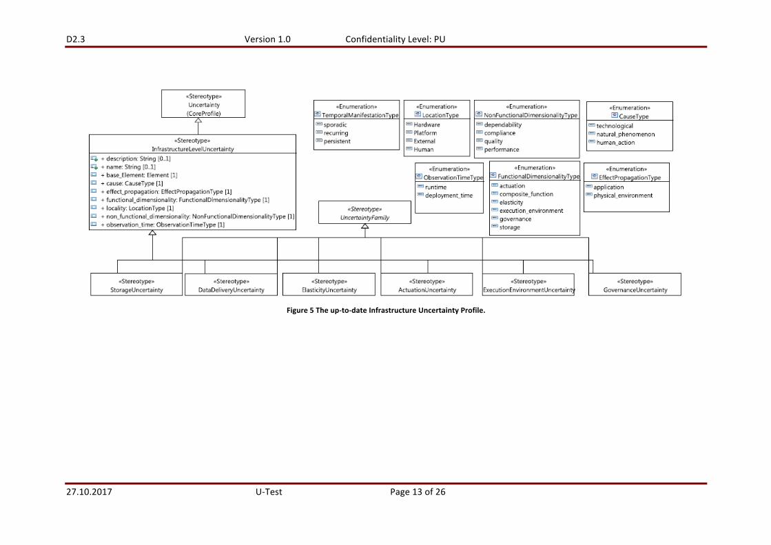
3.3.1 TheInfrastructureUncertaintyProfileBasedonU-Taxonomy,weupdatedtheInfrastructureUncertaintyProfileshowninFigure5.TheInfrastructureUncertaintyprofileextendsthecoreUncertaintystereotype.Inparticular,weintroducetheUncertaintyconceptasstereotypeinadditiontoprofiletypes(i.e.,definingClassattheprofilelevel).The«InfrastructureUncertainty»stereotypeischaracterizedbythefollowingproperties,modelledasUMLEnumerationtypes,namely:
• TemporalManifestationType,• LocationType,• NonFunctionalDimensionalityType,
• CauseType,• ObervationTimeType,• FunctionalDimensionalityType,• EffectPropagationType.
Wethenidentifydifferentspecializationofthe«UncertaintyFamily»stereotypenamely:• DataDeliveryUncertainty,
• ActuationUncertainty,• ExecutionEnvironmentUncertainty,• GovernanceUncertainty,• ElasticityUncertainty,• StorageUncertainty.
Each family is characterized by a particular set of values assigned to infrastructuraluncertaintypropertiesthatdeterminewhetheranuncertaintybelongstoaparticularfamily.Forexample, the functionaldimensionalitypropertyof«StorageUncertainty»stereotype issetbydefaulttostorage.
stereotypedmodelelementsoriginallyplannedtobepartofstaticInfrastructureCPSLibrarythatcanrapidlybecomeobsoleteduetochangestoprofiles.
D2.3 Version1.0 ConfidentialityLevel:PU
27.10.2017 U-Test Page13of26
Figure5Theup-to-dateInfrastructureUncertaintyProfile.

D2.3 Version1.0 ConfidentialityLevel:PU
27.10.2017 U-Test Page14of26
3.3.2 TheInfrastructureCPSProfileTheprevious versionof theCPSprofilewas presented inD2.2 [4]. An excerpt of thenewversionoftheInfrastructureCPSProfilewithStereotypes3andtheirrelationshipsisdepictedinFigure6.
Figure6.PackageDiagramoftheInfrastructureCPSProfile.
Thegoalsofthisnewversionare:
• Tohighlightthedesignrulesbehindtheprofiledefinitionandtorefinetheextensionrelationships between stereotypes and UML meta-classes (e.g., replace Elementmeta-classwithClassone) to suitablynarrowthescopeof stereotypeapplications(e.g.,fromanymodelelementonanydiagramtoClassdepictedonClassDiagrams)thustamingthecomplexityofmodellingactivityinUMF.
• To structure the profile in packages to group stereotypes with respect to thepurposes (see Figure 6) they are modelling (i) edge and cloud infrastructures(Infrastructure Modelling package) and (ii) test configurations (TestConfigurationModellingpackage).
The next subsections detail the InfrastructureModelling and TestConfigurationModellingpackagesofthenewversionoftheInfrastructureCPSProfile.
3.3.2.1 InfrastructureModellingPackage
OneofthemaingoalsoftheInfrastructureCPSProfileisrepresentingtheInfrastructureand its constituting InfrastructureElements, both physical and virtual ones, which arepartofthecloud-basedCPS.
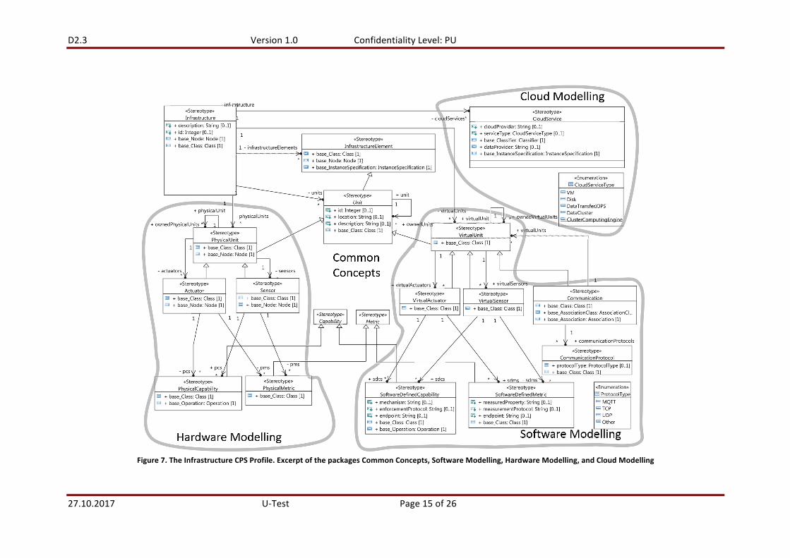
Figure 7 shows an excerpt of the stereotypes and their relationships defined within theInfrastructure CPS Profile. The envisaged Infrastructure CPS includes both software andhardwareUnits.Weaimatrepresentingbothkindsofunitsinaspecularmannertoprovidethesamemodellingexpressiveness,withtheonlyexceptionofcommunicationdevicesandprotocols,asdetailedlater.
3WhenreferringtoStereotypemodelelement,wewritetheterminitalicsandcapitalletter.
D2.3 Version1.0 ConfidentialityLevel:PU
27.10.2017 U-Test Page15of26
Figure7.TheInfrastructureCPSProfile.ExcerptofthepackagesCommonConcepts,SoftwareModelling,HardwareModelling,andCloudModelling

D2.3 Version1.0 ConfidentialityLevel:PU
27.10.2017 U-Test Page16of26
Therefore,wehaveappliedthefollowingdesignrule inthedefinitionofthe InfrastructureCPSProfile,yieldingfoursetsofstereotypes,collectedinthefollowingsub-packages:
• CommonConcepts. This sub-package introduces generic, abstract stereotypes forconceptcrosscuttingsoftwareandplatformrepresentations.
• Software Modelling and Hardware Modelling packages. These sub-packagesdefineconceptstorepresentthesoftwareandhardwareelementsthatbuildupaninfrastructure. We introduce new concrete stereotypes by adding Virtual- andPhysical- prefixes to the name of the generic, abstract stereotypes defined in theCommonConceptssub-package.
• CloudModelling package. This sub-package introduces stereotypes to representcloud-basedelements.
For thesakeofexplanation,werepresentanexcerptof the InfrastructureCPSProfileasaflat Package Diagram where Common Concepts’ stereotypes are connected to otherstereotypesgraphicallygroupedinareasnamedafterthecontainingpackage.
The Infrastructure is composed of multiple, generic Units, each one with its ownidentifier, location, description, and configurationproperties. In particular, a configurationrepresentsthesettingsassociatedtotheUnit.
Units can be divided in PhysicalUnits and VirtualUnits that represent hardware andsoftwareresources,respectively.Bothphysicalandvirtualunitsarecomplexelementsandcanbecomposedofotherphysicalandvirtualunits,respectively.
A PhysicalUnit has associated Actuators and Sensors4, which, in turn, are themselvesparticularkindsofPhysicalUnits.
AnActuatorrepresentsahardwarecomponentthatchangesthestatusofthesurroundingenvironment. EachActuator realizes oneormorePhysicalCapabilities. ASensor is acomponentthroughwhichaPhysicalUnitmonitorsitsenvironment(e.g.,locationtracker,temperaturesensor,humiditysensor).EachPhysicalUnithasassociatedMetricsthatitiscapable to collect. For example, a thermostat physical unit can include both a sensor tocollecttemperatureandhumidity(i.e.,thephysicalcapabilitytocollecttwometrics),andanactuator that has the capability to modify the temperature and the humidity of thesurroundingenvironment.
EachPhysicalUnithasassociatedoneormoreVirtualUnits that runon topof it (e.g.,PLCcoderunningandgoverningmachineswithinaproductionsystem).
Asanticipated,weassumeaspecularsetofconceptstodescribethesoftwarearchitectureof the Infrastructure CPS. A VirtualUnit has associated VirtualActuators and aVirtualSensors,which,inturn,arethemselvesparticularkindsofVirtualUnits.
A VirtualActuator represents a software component through which the owningVirtualUnitcontrolsthehardwareplatformelementsthatinteractwiththeenvironment.EachVirtualActuatorrealizesoneormoreVirtualCapabilities.
AVirtualSensor isa softwarecomponent throughwhichphysical sensorsarecontrolled.EachVirtualUnithasassociatedoneormoreSoftwareDefinedMetricsthatitiscapableto collect (e.g., logical representations of physical measures like temperatures are floatvariables). The SoftwareDefinedMetric has an id,name,description,endpoint,period,measuredProperty,andmeasurementProtocol.Thesearetheattributesneededforaccessingthesensorinformation.
4Inthiscase,termslikeActuatorsandSensorsaredefinitelyhardware-specifictermsandwechoosetonotaddPhysical-prefixtothecorrespondingstereotypes.

D2.3 Version1.0 ConfidentialityLevel:PU
27.10.2017 U-Test Page17of26
Concerningthemodellingofcommunicationunitsandprotocols,it isworthnotingthatwedidnotintroduceaspecificstereotypeforcommunicationdevices,likeroutersorcables,butwe plan to model them as PhysicalUnits. On the contrary, we introduce a specificCommunication stereotype to model interactions between VirtualUnits. Eachcommunication realizes a particular ProtocolType between different infrastructureelements.ThesupportedprotocolsvaluesareMQTT,HTTP,TCP,UDP,AMQP,andSTOMP.
We thenmap stereotypes toUMLmeta-classes to determinewhichmodel elements theycan be applied to and, then, in which UML diagrams they can appear. In Figure 7, theextended UML meta-class is referred by the «base_class» stereotype property. All theaforementioned stereotypes define structural modelling concepts. For this reason, thechosen UML meta-classes are Class, Component, and InstanceSpecification for bothsoftware and platform related concepts. Therefore, the UMLmodeller can (i) define newinfrastructural element types via Classes, Components and Nodes, (ii) instantiate typedobjects via InstanceSpecification, and (iii) depict them on Class, Component, andDeploymentdiagrams.
3.3.2.2 TestConfigurationModellingPackageFigure8showsasetofstereotypesfromtheInfrastructureCPSProfiledefinedtorepresent,in UML, test configurations. These stereotypes complement those included in theInfrastructureModellingpackagedepictedinFigure7.
Figure8.TestConfigurationModellingpackage
FortestingCPS,weassociateaTestConfigurationtoMetric,beinganextensionpointforfurthertypesoftests.TheTestConfigurationhasaname,descriptionandatestTimeout.The testTimeout gives the maximum amount of time in which the associatedTestExecutorshouldanswerthetest.TheTestExecutorhasanassociationtoCapabilityortoSoftwareDefinedCapability,forthecaseinwhichcertainsettingsneedtobedoneon theCPSbefore the test is executed. TheTestExecutorowns a description, a Booleanstatingwhether the unit executing this test is different from the target of the test, and atargetdescribingthetargetofthetest.
D2.3 Version1.0 ConfidentialityLevel:PU
27.10.2017 U-Test Page18of26
Each TestConfigurationhas associated a TestTrigger, which describes when the testshould be executed. The TestTrigger is of two types, either EventTrigger orPeriodicTrigger. TheEventTriggeris used for event-based testing (e.g.,when, duringsystem runtime, the quality is too low). The EventTrigger has two attributes: thedescription of the event, and the eventSource. The PeriodicTriggeris used for testsexecuted in specific periods described under various units of time. ThePeriodicTriggerhastwoattributes:theperiodandthetimeUnit.
Finally, any CPS is equipped with CloudServices of different types (seeCloudServiceTypes enumeration including VM, Disk, StorageService, andDataAnalyticsEngine) corresponding to cloud offerings by cloudProvider anddataProvider.
ItisworthnotingthatwehavedesignedthestereotypesbelongingtotheTestConfigurationModelling package to be applicable on both Classes and InstanceSpecificationmodelelements. Therefore, the UMF user can specify tests both referring to SUT architecturaltypes (i.e., Classes, Operationsand Associationsdepicted on Class Diagrams) or usecase specific configurations made of graph of connected architectural instances (i.e.,InstanceSpecification,LinksandSlotvalues5).
4 UpdatesonModellingMethodologyThis section presents the updates in the modelling methodology at the integration level(Section4.1),applicationlevel(Section4.2),andinfrastructurelevel(Section4.3)ofCPS.
4.1 UpdatesintheMethodologyattheIntegrationLevel
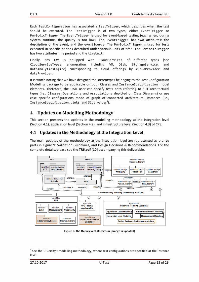
Themain updates of themethodology at the integration level are represented as orangeparts inFigure9:ValidationGuidelines,andDesignDecisions&Recommendations.Forthecompletedetails,pleaseseetheTR6.pdf[10]accompanyingthisdeliverable.
Figure9.TheOverviewofUncerTum(orangeisupdated)
5SeetheU-CertifyItmodellingmethodology,wheretestconfigurationsarespecifiedatthe instancelevel

D2.3 Version1.0 ConfidentialityLevel:PU
27.10.2017 U-Test Page19of26
Tofacilitatetheconstructionoftest-readymodelswithourmethodology,wehave listedasetofdesigndecisionsand recommendationsas shown inFigure9.Theyaresummarized,alongwiththerationalesbehindinTable4oftheaforementionedTR6.pdf[10].
Toensurethattest-readymodelsaresyntacticallycorrectandcommunicationacrossstatemachines of various physical units constituting a CPS takes place correctly, we havedeveloped the validation process (Figure 9) with step-wise guidelines and a set ofrecommendationsto fixproblems intest-readymodels.Suchvalidation isaimedat findingmodellingerrorsthatmayhavebeenintroducedbyatestmodelleraccidentally.Oncetest-readymodelshavebeensuccessfullyvalidated,testcasescanbethengeneratedfromthem.Sincetheexecutionoftest-readymodelsrequiresdatatoexecutetriggers,wegeneratedataas follows: 1) if a trigger (Call Event/Signal Event) is guarded by a guard condition, wegeneraterandomvaluesforallthevariablesinvolvedintheguardconditionthatsatisfytheguardconditionandusethesevaluestofirethetrigger,andgeneraterandomvaluesforalltheotherparametersofthecallevent/signalevent,2)ifatrigger(CallEvent/SignalEvent)isnot guarded, we generate random values for all the parameters of the Call Event/SignalEventtofirethetrigger,3)ifatriggercorrespondstoaChangeEvent,werandomlygeneratevalues that satisfy the change condition, 4) if a trigger corresponds to a Time Event, weensurethatthespecifiedperiodoftimeintheeventiselapsed.Formoredetails,seeSection8oftheTR6.pdf[10]accompanyingthisdeliverable.
To ease the modeling indeterminacy source, we summarize our recommendations forapplying the indeterminacy source profile (Table 1) and update the activity diagram formodellingindeterminacysource(Figure10).Formoredetails,seeSection2.1.3and4.5.2.BoftheTR9.pdf[9]accompanyingthisdeliverable.
Table1.RecommendationsforapplyingtheIndeterminacySourcepartoftheUUP
# Stereotype Applied Base Element S1: States of the environment of the CPS are indeterminate, such as the batteryStatus. R1 «IndeterminacySource» Property «IndeterminacySpecification» Constraint Op1 «IndeterminacySourceInput» Operation Op2 «IndeterminacySourceInput» Operation, Constraint R2 «IndeterminacySource» Constraint «IndeterminacySpecification» FALSE (default) Op1 «IndeterminacySourceInput» Operation Op2 «IndeterminacySourceInput» Operation, Constraint S2: Input data is indeterminate. R1 «IndeterminacySource» Operation «IndeterminacySpecification» Constraint «IndeterminacySourceInput» Constraint S3: Occurrences of an event from the environment (e.g., “pressing the button”) are indeterminate. R1 «IndeterminacySource» Property «IndeterminacySpecification» Constraint Op1 «IndeterminacySourceInput» Operation Op2 «IndeterminacySourceInput» Operation, Constraint R2 «IndeterminacySource» Constraint «IndeterminacySpecification» FALSE (default) Op1 «IndeterminacySourceInput» Operation Op2 «IndeterminacySourceInput» Operation, Constraint

D2.3 Version1.0 ConfidentialityLevel:PU
27.10.2017 U-Test Page20of26
Figure10.ModelIndeterminacySource
D2.3 Version1.0 ConfidentialityLevel:PU
27.10.2017 U-Test Page21of26
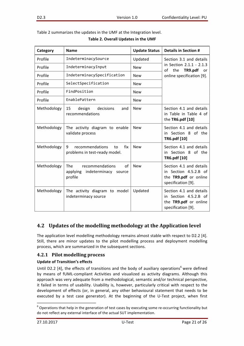
Table2summarizestheupdatesintheUMFattheIntegrationlevel.Table2.OverallUpdatesintheUMF
Category Name UpdateStatus DetailsinSection#
Profile IndeterminacySource Updated Section 3.1 and detailsin Section 2.1.1 - 2.1.3of the TR9.pdf oronlinespecification[9].
Profile IndeterminacyInput New
Profile IndeterminacySpecification New
Profile SelectSpecification New
Profile FindPosition New
Profile EnablePattern New
Methodology 15 design decisions andrecommendations
New Section 4.1 and detailsin Table in Table 4 oftheTR6.pdf[10]
Methodology The activity diagram to enablevalidateprocess
New Section 4.1 and detailsin Section 8 of theTR6.pdf[10]
Methodology 9 recommendations to fixproblemsintest-readymodel.
New Section 4.1 and detailsin Section 8 of theTR6.pdf[10]
Methodology The recommendations ofapplying indeterminacy sourceprofile
New Section 4.1 and detailsin Section 4.5.2.B ofthe TR9.pdf or onlinespecification[9].
Methodology The activity diagram to modelindeterminacysource
Updated Section 4.1 and detailsin Section 4.5.2.B ofthe TR9.pdf or onlinespecification[9].
4.2 UpdatesofthemodellingmethodologyattheApplicationlevel
TheapplicationlevelmodellingmethodologyremainsalmoststablewithrespecttoD2.2[4].Still, there are minor updates to the pilot modelling process and deployment modellingprocess,whicharesummarizedinthesubsequentsections.
4.2.1 PilotmodellingprocessUpdateofTransition’seffectsUntilD2.2[4], theeffectsoftransitionsandthebodyofauxiliaryoperations6weredefinedby means of fUML-compliant Activities and visualized as activity diagrams. Although thisapproachwasveryadequatefromamethodological,semanticand/ortechnicalperspective,it failed in termsofusability.Usability is, however, particularly criticalwith respect to thedevelopment of effects (or, in general, any other behavioural statement that needs to beexecuted by a test case generator). At the beginning of the U-Test project, when first6Operationsthathelpinthegenerationoftestcasesbyexecutingsomere-occurringfunctionalitybutdonotreflectanyexternalinterfaceoftheactualSUTimplementation.

D2.3 Version1.0 ConfidentialityLevel:PU
27.10.2017 U-Test Page22of26
considerationsabouttheU-TestUMFwheredone,itwasexpectedtoutilizethePapyrusAlfeditor,whichproducesfUML-ActivitiesfromtextualAlfstatements.Backinthosedays,thiswas considered (and it still is) the easiest, yet most elegant and usable way to developtransition effects and auxiliary methods. Unfortunately, the Papyrus Alf editor did notmatureintimeforareliableusagewithintheU-Testproject(itwasstillnotfully-fledgedandmatureintheEclipseMarsrelease,i.e.,afterM18oftheU-Testduration).After reconsidering how to circumvent this pure technical issue, we decided to go for adirect modelling of the corresponding activity diagrams – corresponding in terms of theactivitydiagramsthatwouldhavebeengeneratedbythePapyrusAlfeditor.Although,froma semantic point of view, this was exactly what was required for the application levelprocess,changestotheusecasesandtransitivelytotheaffectedactivitydiagramsrequireda huge and ineffectivemaintenance effort. Furthermore, the end userswould have to beexperts inmodellingtheexecutableactivitydiagramsonwhichwerelied.SincethiswouldimposeatoohightechnicalbarrierontheindustrialadoptionoftheU-Testapplicationlevel,wedecided,after theexperiencesofD2.2 [4]withactivitymodelling, toevengoone-stepback and directly include the required C# code. This C# snippet was intended to begeneratedfromtheexecutableactivitydiagramsbeforehandinordertogeneratetestcasesfromtheunderlyingC#-basedenginefortestgeneration.DuetomissingstabilityofthePapyrusAlfEditoratfirst,andtheinfeasibleactivitymodellingbarrier at second, the final update of the pilotmodelling process has shifted towards thedirectusageofC#codetoexpresstransitioneffectsandauxiliarybehaviour.
4.2.2 UncertaintymodellingNochangeswithrespecttoD2.2[4].
4.2.3 DeploymentmodellingThe specification of test directiveswas already described in D2.2 [4] to a certain degree.Sincethen,thetestdirective-basedmodellingmethodologywasfurtherdevelopedinorderto simplify the entire deployment and automationprocess. There arenow threedifferentkindsoftestdirectivesdefinedfortheUMF,technicallyrepresentedassub-typesoftheUTPstereotype«TestDesignDirective».Theseare:
• UTFTestDirective;• TestCaseGenerationDirective;
• TestCodeGenerationDirective;• TestExecutionDirective;• UTFModelEvolutionConfigurationandGenerationSizeStrategy.
These test directives serve different purposes in the UMF test automation architecture(Fokus!MBTU-Test).Theyaimatacompletelyautomatedtestprocesswithoutanymanualintervention.The UTFTestDirective is a test directive specially tailored for U-Test that acts as acontainerforthetestautomationprocessrequireddirectives.TheUTFTestDirectiveactsas theexecutableentrypoint into theautomateduncertainty testingprocess. It combinesthedirectivesforbothautomatedtestgenerationandautomatedtestexecution.Whentheuser executes the UTFTestDirective, the entire automated tool chainwill be setup andconfigured automatically. The result of the test generation sub-process (if successful) is anumberofUTPtestscripts.Technically,aUTFTestDirectiveisdefinedasanextensionoftheUTP2testdesignfacility,i.e. a stereotype that specializes the UTP stereotype «TestDesignDirective». ThecorrespondingprofilespecificationisshowninFigure11.

D2.3 Version1.0 ConfidentialityLevel:PU
27.10.2017 U-Test Page23of26
Figure11.SpecificationoftheUTFTestDirective
Thestereotypes«UTFTestCaseGenerationDirective»and«UTFTestCodeGenerationDirective»are similar concepts but only for the purpose of test case generation and generation ofexecutable test scripts. Both parts represent the corresponding manual activities ingeneratinglogicaltestcasesandimplementingexecutabletestcases.The UTFModelEvolutionConfiguration serves the purpose of configuring the modelevolution intermsofpopulationsize,crossoveractivation(seeD3.3[7] for furtherdetails)and the generation size strategy. The generation size strategy determines how manygenerations shall be generated by search-based algorithm for revealing new uncertainbehaviour of the system under test. The application level UMF supports currently a fixgenerationsizestrategy(representedbythestereotype«FixGenerationSize»)thatwhencertainnumberofgenerationshasbeengenerated,used for testcasegenerationandtestcaseexecution.Thelong-termgoalinthisregardistoreplacethefixgenerationsizestrategywithadynamicgenerationsizestrategy.Thisonewouldthenusetheoutcomeofeachtestcaseexecutionofeachgenerationinordertocheckwhetherthedesiredresult(intermsofafitnessfactorthreshold)hasbeenfound.Thiswouldallowanoptimizedautomationprocessbased on the search-based problem as opposed to finishing testing after a fix number ofgenerations.TheTestExecutionDirectiveabstractsfromconcretedeploymentmodellingandcreatesadeployment specification for automated test case execution (automated start of theexecution of the test cases that have been generated). Furthermore, the entire testexecution system (JUnit in case of U-TEST project) is automatically setup and the JUnitengine gets started. After test execution, the test logs are feedback and evaluated foreventualverdictcalculation.
Furthermore, the UTFTestDirective couples the known application level uncertainties(which serve as the basis for the model evolution algorithm in order to detect furtherunknown uncertainties) with a concrete U-Test test strategy (the different strategies aredescribed in detail in D3.2 [6]). The underlying test automation engine exploits thisinformationtoconfigureandsteerthemodelevolutionimplementationlateron.TheUMLprofilefortheapplicationlevelteststrategiesisshowninFigure12.

D2.3 Version1.0 ConfidentialityLevel:PU
27.10.2017 U-Test Page24of26
Figure12.UMLprofileforapplicationlevelUMF
Summary
With respect to thedeploymentofeventuallyexecutable test cases,aUTFTestDirectiveencapsulates all information and generates the respective UML deployment specificationautomatically,insteadofimposingthesesubtlemodellingstepsonthetestengineer.Thesechangesinthedefinitionofthedeploymentmodellingprocessareamajorsteptowardsthesimpler application, increase usability of the UMF. For these reasons, it has beenimplementedintherecentversionoftheFokus!MBTUTEST.
4.3 UpdatesoftheInfrastructurelevelmodellingmethodology
The infrastructure level profile has been further extended to model different kinds ofinfrastructural elements (IoT hardware/software components and cloud services) as types(by extending the UML Class meta-class) and instances (by extending the UMLInstanceSpecificationmeta-class).Since theevolutionprocessofnon-standardprofilesis supposed to continue to accommodate different needs of users and tool vendors, weintroduce inD3.3 [7] amethodologyand tool thatadapt to changes toprofilesapplied toUMLModel.
4.4 Test-ReadyModelsforPilots
Theapplicationof theUMFyields test-readymodelsasoutputs,whicharebasedonUMLandtheUTPandUUPprofiles.Ingeneral,testmodellersshouldbeguidedbytheprovidedmodellingmethodology inorder tocreatethesetest-readymodels.Thegoal is toproducemodelsthataredefinedatasufficient levelofdetail togenerateadequatetestcases.Thetest-readymodelsforbothpilotsaredescribedintheDeliverableD2.4[5].
5 SummaryIn general,wehavemade significant improvements fromUMFV2 toUMFV3 in termsofcompleting the modelling methodology, and the modelling support such as the UUP forbetter supporting modelling indeterminacy source. Moreover, we have also shown theapplication of UMF V3 in completing the test-ready models for the two industrial case
D2.3 Version1.0 ConfidentialityLevel:PU
27.10.2017 U-Test Page25of26
studies (D2.4 [5]). The detailed achievements in UMF V3 at the CPS’s integration level,applicationlevel,andinfrastructurelevelaresummarizedasfollows.
5.1 UMFforIntegrationLevel
WehavereachedthemilestoneMx4regarding theUMFV.3 (finalversion) foruncertaintymodellingattheintegrationlevelofCPS.ComparingwithUMFV.2,themainimprovements,asshowninFigure9,(page18)foruncertaintymodellingattheintegrationlevelinclude:
1) TheupdateoftheUUPforsupportingmodellingindeterminacysource,whichleadstooccurrenceoftheuncertainties.
2) Theimplementationofthevalidationprocesstoensurethesyntacticallycorrectnessoftest-readymodels.
3) Thesummarizeddesigndecisionsandrecommendationstoprovidemodellerswithoptionstoconstructtest-readymodelsusingUMFV.3attheintegrationlevel.
WepresentintheaccompanyingD2.4[5]theimplementationof100%usecasesforthetwocasestudiesattheintegrationlevel.
5.2 UMFforApplicationLevel
Milestone Mx4 (UMF V.3) has been successfully reached with respect to uncertaintymodelling at the application level. Themajor updates in UMF V.3 targeted the followingaspects:
• Pilotmodellingprocess:UseofC#actioncodeinsteadoffUML-compliantActivitiesduetotechnicalreasons.
• Deploymentmodellingprocess:IntegrationofU-Test-specifictestdirectivestodrivetheentiredynamictestprocess
5.3 UMFforInfrastructureLevel
WehavereachedthemilestoneMx4regardingtheUMFV.3foruncertaintymodellingattheinfrastructure level of CPS. When compared to UMF V.2, the main improvements forinfrastructurelevelmodellingattheinfrastructurelevelinclude:
• UpdatedInfrastructureUncertaintyProfile.Weintroducedstereotypedefinitionsinadditiontoprofiletypes(i.e.ClassesdefinedinUMLprofiles),andnewenumeratedtypestodistinguishamongdifferentkindsofinfrastructureuncertaintyfamilies.
• Updated InfrastructureCPS Profile with clear distinction among IoT and cloudinfrastructuralelements.
It is worth noting that we introduce wizards as part of the Uncertainty Modelling andEvaluation methodology and tool in D3.3 [7] to automatically adapt infrastructure levelmodellingguidelinestochangesinprofilesappliedtoUMLmodels.

D2.3 Version1.0 ConfidentialityLevel:PU
27.10.2017 U-Test Page26of26
6 Bibliography[1] D1.1:U-TestDeliverableReportonRequirementsCollection.[2] D1.2:U-TestDeliverableReportonUncertaintyTaxonomy.[3] D2.1:U-TestDeliverableReportonUncertaintyModellingFramework(UMF)V1.[4] D2.2:U-TestDeliverableReportonUncertaintyModellingFramework(UMF)V2.[5] D2.4:U-TestDeliverableReportonUncertaintyModellingFramework(UMF)V3:The
Test-ReadyModelsofPilots.[6] D3.2:U-TestDeliverableReportonUncertaintyTestingFrameworkV.2.[7] D3.3:U-TestDeliverableReportonUncertaintyTestingFrameworkV.3.[8] Truong,H.-L.,L.Berardinelli,I.Pavkovic,andG.Copil.ModelingandProvisioningIoT
CloudSystemsforTestingUncertainties.inThe14thEAIInternationalConferenceonMobileandUbiquitousSystems:Computing,NetworkingandServices(MobiQuitous).2017.Melbourne,Australia:ACM.
[9] Zhang,M.,S.Ali,T.Yue,andP.H.Nguyen,UncertaintyModelingFrameworkfortheIntegration Level V.3. Technical Report, 2016. 2016-01. Available from:https://www.simula.no/publications/uncertainty-modeling-framework-integration-level-v2.
[10] Zhang,M.,S.Ali,T.Yue,R.Norgren,andO.Okariz,Uncertainty-WiseCyber-PhysicalSystemtestmodeling.Software&SystemsModeling,2017.