physically motivated reduction of a 2d dynamic model for molten carbonate fuel cells (mcfc)
TRANSCRIPT
Physically Motivated Reduction of a 2DDynamic Model for Molten CarbonateFuel Cells (MCFC)M. Gundermann1, P. Heidebrecht2, and K. Sundmacher1,2*1 Process Systems Engineering, Otto-von-Guericke-University, Universitätsplatz 2, Magdeburg 39106, Germany2 Max Planck Institute for Dynamics of Complex Technical Systems, Sandtorstraße 1, Magdeburg 39106, Germany
Received July 13, 2007; accepted January 17, 2008
1 Introduction
Fuel cells are efficient energy converters that produce elec-tric energy and heat from chemical fuels. They can reachhigher efficiencies than conventional plants and they havesignificant advantages concerning pollution and noise emis-sion.
Among the various types of fuel cells, the molten carbo-nate fuel cell (MCFC) is especially suitable for stationary ap-plications. It has a very high fuel flexibility and can beapplied for combined heat and power generation. Due totheir high electric efficiency, an MCFC shows a better ratio ofelectric power to heat output than conventional energy con-verters, a feature very favourable for many applications.
The operating temperature of the MCFC is at 550–650 °Cwhich has a number of advantages compared to other typesof fuel cells. The temperature is sufficiently high to use lessnoble electrode catalysts like nickel. Because these catalystsare tolerant with respect to carbon monoxide, different mix-tures of short-chain hydrocarbons, hydrogen and carbonmonoxide can be applied in MCFC. Besides natural gas, thisalso includes biogas, sewage gas, mine gas, landfill gas, coalgas and coal gasification products. The second advantage ofthe high operating temperature is the possibility to applyinternal reforming. Especially, the direct internal reforming
(DIR) within the anode channels offers the chance to realise acompact system design and reach higher efficiencies by sub-stantial direct coupling and reforming of the heat demandingand fuel producing thermal processes and the heat producingand fuel consuming electrochemical reactions. However, thetemperature is still low enough to allow the MCFC to bemade of metal-based materials instead of ceramics.
Currently, the MCFC technology is on the edge of com-mercialisation. During the last two decades the main techni-cal problems have been solved and the manufacturers ofMCFC systems installed many pilot plants around the world.The most important challenges at the moment are the costreduction and further improvement of the cell performance[1, 2]. In these ongoing developments, there is a strong needfor a better understanding of the process at steady state andunder transient conditions and for suitable methods for pro-cess control and optimisation. However, high temperaturefuel cells represent highly nonlinear and spatially distributedsystems with a very complex system behaviour. The reasonsfor this are the inherent nonlinearity of the electrochemicalreaction kinetics as well as the intense coupling between mass
–[*] Corresponding author, [email protected]
AbstractThe reduction of a molten carbonate fuel cell (MCFC) modelis presented. It starts from a reference model, which includesdirect and indirect internal reforming as well as a catalyticcombustion and a reversal chamber between anode andcathode channels. The reference model is dynamic, spatiallydistributed and strictly based on balances of mass, enthalpyand charges. In order to reduce the numerical effort of themodel simulations and to retain as much detailed informa-
tion on the system behaviour as possible, the model is sys-tematically reduced by identifying negligible physical andchemical processes. All model reductions are discussed indetail. To evaluate the effects of the applied changes, thereduced model is compared to the reference model.
Keywords: Mathematical Modelling, MCFC, Molten Carbo-nate Fuel Cell, Internal Reforming, Reduced Model
96 © 2008 WILEY-VCH Verlag GmbH & Co. KGaA, Weinheim FUEL CELLS 08, 2008, No. 2, 96–110
ORIG
INAL
RES
EARCH
PAPER
DOI: 10.1002/fuce.200700040
Gundermann et al.: Physically Motivated Reduction of a 2D Dynamic Model ...
transfer, reactions and heat transport. Inaddition, the different compartments of thecell are externally coupled via the catalyticcombustion, which means that the cathodefeed depends on the anode exhaust gas.
Thus, mathematical models are necessarytools for further MCFC development. Thetwo MCFC models discussed in this contri-bution serve the same purposes. Theseinclude the analysis of the system at steady-state operation, the optimisation of steady-state operating conditions with respect toefficiency and temperature profile and theoptimisation of MCFC design parameters[3–6]. These aims not only improve theunderstanding of the system behaviour andthe system efficiency, but they also have asignificant impact on the lifetime of the sys-tem. Furthermore, these models are usedto develop online observer systems whichallow to monitor nonmeasurable states with-in the system, and to derive optimal control strategies [6, 7].The last two aspects require transient models and increasethe efficiency and safety of MCFC operation, because the stateof the system is known completely during operation and canbe predicted reliably.
The model on which these developments are based has tobe dynamic and must describe the spatially distributed con-centrations and temperatures as well as the cell voltage andthe electric cell power. Therefore, a number of physical andchemical phenomena have to be considered. But, especiallyfor control and optimisation purposes, it is important that themodel is lean and can be solved within reasonable time.Hence, only those phenomena should be included into themodel that have a relevant influence on the system behav-iour. In addition, the model simulations should correspond tothe behaviour of a real MCFC.
Such a reduced MCFC model is presented in this paper. Atfirst, some technical background on MCFCs is given. Next, acomplex and detailed MCFC is introduced as the referencemodel, which had been adapted to an industrial MCFC plant.Then, this model is systematically reduced by identifyingnegligible physical and chemical processes. Finally, theresults of the presented model reduction strategy are dis-cussed.
2 MCFC Working Principle
In 1960, the first successful operation of an MCFC has beenreported by the Dutch scientists G. H. J. Broers and J. A. A.Ketelaar [8, 9]. Although important progress has been madein improving the materials and the system design since then,the actual working principle of the MCFC is still the same.
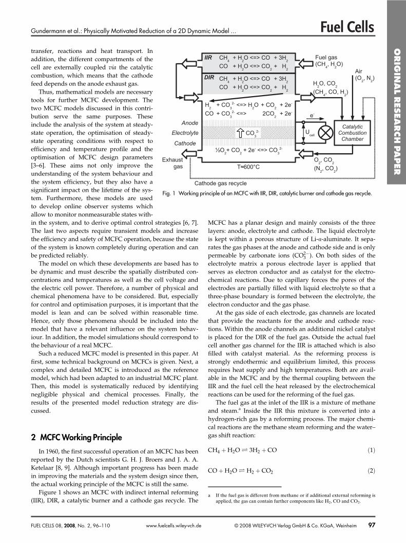
Figure 1 shows an MCFC with indirect internal reforming(IIR), DIR, a catalytic burner and a cathode gas recycle. The
MCFC has a planar design and mainly consists of the threelayers: anode, electrolyte and cathode. The liquid electrolyteis kept within a porous structure of Li-a-aluminate. It sepa-rates the gas phases at the anode and cathode side and is onlypermeable by carbonate ions (CO2�
3 ). On both sides of theelectrolyte matrix a porous electrode layer is applied thatserves as electron conductor and as catalyst for the electro-chemical reactions. Due to capillary forces the pores of theelectrodes are partially filled with liquid electrolyte so that athree-phase boundary is formed between the electrolyte, theelectron conductor and the gas phase.
At the gas side of each electrode, gas channels are locatedthat provide the reactants for the anode and cathode reac-tions. Within the anode channels an additional nickel catalystis placed for the DIR of the fuel gas. Outside the actual fuelcell another gas channel for the IIR is attached which is alsofilled with catalyst material. As the reforming process isstrongly endothermic and equilibrium limited, this processrequires heat supply and high temperatures. Both are avail-able in the MCFC and by the thermal coupling between theIIR and the fuel cell the heat released by the electrochemicalreactions can be used for the reforming of the fuel gas.
The fuel gas at the inlet of the IIR is a mixture of methaneand steam.a Inside the IIR this mixture is converted into ahydrogen-rich gas by a reforming process. The major chemi-cal reactions are the methane steam reforming and the water–gas shift reaction:
CH4 � H2O � 3H2 � CO �1�
CO � H2O � H2 � CO2 �2�
Fig. 1 Working principle of an MCFC with IIR, DIR, catalytic burner and cathode gas recycle.
a If the fuel gas is different from methane or if additional external reforming isapplied, the gas can contain further components like H2, CO and CO2.
ORIG
INAL
RES
EARCH
PAPER
FUEL CELLS 08, 2008, No. 2, 96–110 © 2008 WILEY-VCH Verlag GmbH & Co. KGaA, Weinheim 97www.fuelcells.wiley-vch.de
Gundermann et al.: Physically Motivated Reduction of a 2D Dynamic Model ...
The gas at the outlet of the IIR, which is already reformedto a large extent, is afterwards fed into the anode channels. Inthe pores of the anode, hydrogen and carbon monoxide reactelectrochemically forming water and carbon dioxide:
H2 � CO2�3 � H2O � CO2 � e� �3�
CO � CO2�3 � 2CO2 � 2e� �4�
Simultaneously to the electrochemical reaction, the DIRprocess occurs in the anode channel, continuously providingnew educts for the electrode reaction. Thus, the equilibriumlimitation of the reforming reactions is circumvented.
Because complete fuel conversion is not possible, theanode exhaust gas still contains some combustible species.The gas is mixed with fresh air in a catalytic combustionchamber and is completely oxidised. Besides the electrochem-ical reactions, this combustion is the major heat source in thesystem. The amount of cold air is an important variable tocontrol the temperature within the cell.
The combustion exhaust gas is supplied to the cathodechannels. Here carbon dioxide and oxygen form new carbo-nate ions that migrate back to the anode through the electro-lyte:
CO2�3 � 1�2 O2 � CO2�2e� �5�
At the end of the cathode channels the exhaust gas leavesthe system, whereas in some MCFC systems the gas is partlyrecycled to the catalytic combustion chamber to homogenisethe cell temperature.
3 Detailed Reference Model
Because MCFC are high temperature fuel cells, tempera-ture is a crucial issue in these systems. Low temperaturereduces the catalytic activity of the electrodes leading todecreased cell voltage. Also, the reforming process is sloweddown considerably. High temperature is preferable for elec-tric efficiency, but accelerates degradation processes. Theseissues gain more importance in larger cells where the temper-ature has a spacial profile. Knowledge and, ultimately, con-trol of this profile is a key to long lifetime, efficient and safeoperation and thereby economic success of this system. Itaffects every purpose mentioned in Section 1, so this state isconsidered the most important in the MCFC models treatedhere. Another quite important output of the model is the cellvoltage, because for a given average current density, this vari-able determines the electrical power output and the effi-ciency, and this has a strong impact on the energy balance ofthe system.
The model should describe the cell temperature profileand the cell voltage as a function of operating conditions suchas amount, composition and temperature of the feed flow,
amount of air, cathode gas recycle ratio and total cell current,which are considered as input parameters. This leads to thenecessity to model additional states such as the spatiallydistributed gas compositions, current densities and gas velo-cities. Application of the model for system analysis and opti-misation requires a physically interpretable model. Further-more, in order to serve as a basis for optimal control design,the model must describe the dynamics of the process. Thiscan be achieved by applying dynamic balancing of mass,enthalpy and charges and avoiding highly empirical correla-tions.
An MCFC-model that meets all these requirements hasbeen developed by Heidebrecht [3, 5]. Although there aresimiliar models from other authors like Bosio et al. [10] andFermeglia et al. [11], the model from Heidebrecht is especiallysuitable for our purposes since it has been recently adaptedto an industrial MCFC plant [6, 12, 19]. In the following, thestructure and the main assumptions of the MCFC model arepresented in a compact form. Thereby only the governingequations for IIR, anode, cathode and solid are given. Formore detailed information on the model equations and theirderivation the reader may refer to refs. [3, 5, 6, 12]. At the endof this section a few comments on the parameter estimationare given and the functionality of the model is demonstratedby selected steady-state simulation results.
3.1 Model Structure
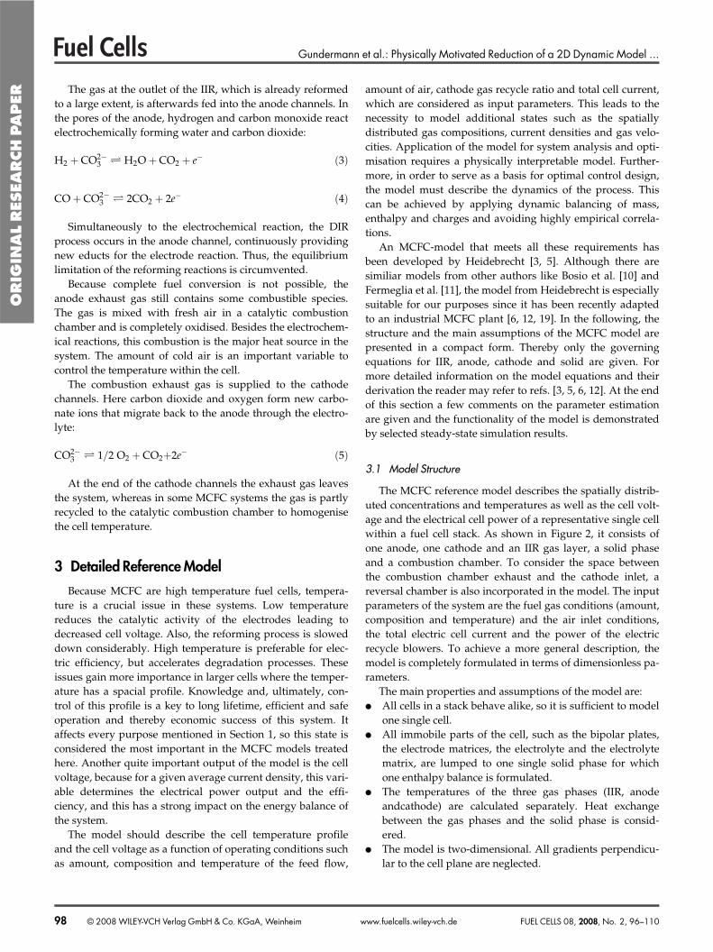
The MCFC reference model describes the spatially distrib-uted concentrations and temperatures as well as the cell volt-age and the electrical cell power of a representative single cellwithin a fuel cell stack. As shown in Figure 2, it consists ofone anode, one cathode and an IIR gas layer, a solid phaseand a combustion chamber. To consider the space betweenthe combustion chamber exhaust and the cathode inlet, areversal chamber is also incorporated in the model. The inputparameters of the system are the fuel gas conditions (amount,composition and temperature) and the air inlet conditions,the total electric cell current and the power of the electricrecycle blowers. To achieve a more general description, themodel is completely formulated in terms of dimensionless pa-rameters.
The main properties and assumptions of the model are:● All cells in a stack behave alike, so it is sufficient to model
one single cell.● All immobile parts of the cell, such as the bipolar plates,
the electrode matrices, the electrolyte and the electrolytematrix, are lumped to one single solid phase for whichone enthalpy balance is formulated.
● The temperatures of the three gas phases (IIR, anodeandcathode) are calculated separately. Heat exchangebetween the gas phases and the solid phase is consid-ered.
● The model is two-dimensional. All gradients perpendicu-lar to the cell plane are neglected.
ORIG
INAL
RES
EARCH
PAPER
98 © 2008 WILEY-VCH Verlag GmbH & Co. KGaA, Weinheim FUEL CELLS 08, 2008, No. 2, 96–110www.fuelcells.wiley-vch.de
Gundermann et al.: Physically Motivated Reduction of a 2D Dynamic Model ...
● The model is transient and therefore, suitable for controldesign purposes.
● No pressure drop is considered along the gas channels, soisobaric conditions are assumed.
● The temperature-dependent chemical equilibrium con-stants and standard open-circuit voltages are approxi-mated by linear functions.
For the modelling of the gas phases, additional assump-tions are made:● The anode and cathode gas channels are arranged in a
cross-flow configuration while the IIR flow direction iscounter-current to the anode.
● Ideal gas law is applied to the gas phases.● Gas flow occurs only in one direction, without any veloci-
ty components perpendicular to the flow direction (nocross-linked channels).
● Reforming reactions in the anode and IIR channels aremodelled as quasi-homogeneous gas phase reactionsusing volume-related reaction rates.
● Axial gas diffusion is negligible compared to convectivemass transport.
● Heat conduction in the flow direction is negligible com-pared to convective heat transport. Heat transfer betweenelectrode and gas phase is described by a linear function.The heat transfer coefficient includes the effect of thermalradiation in a linearised form.
With these assumptions, the component mass balances[Eq. (6)], the enthalpy balance [Eq. (7)] and the total mass bal-ance [Eq. (8)] describe the mole fraction, vi, the temperature, �and the molar flow density, c, in the gas channels:
Va
�a
∂vi�a
∂s� �ca
∂vi�a
∂f1��j�ox
mi�j � vi�a �mj
� �Dajrj
��
j�a�ref
mi�j � vi�a �mj
� �Dajrj
�6�
Va
�a
∂�a
∂s� �ca
∂�a
∂f1��
j�a�ref
�DRhhj �a� �
� � Dajrj�i vi�acp�i
��j�ox
Dajrj
�i m�ij cp�i�i vi�acp�i
��s � �a� �qas�
i vi�acp�i
(7)
0 � � ∂ca�a
∂f1��j�ox
Dajrj
�i m�ij cp�i�i vi�acp�i
�s � �a� �
��
j�a�ref
�DRhhj �a� �
� � Dajrj�i vi�acp�i
� qas�i vi�acp�i
��a
�j�a�ref
�mj Dajrj � �a
�j�ox
�mj Dajrj
�8�
The equations are exemplarily given for the anode chan-nels since the equations are very similar for the other two gasphases. In the case of the IIR, the electrochemical reactions(ox) are omitted while in the cathode channels no reformingreactions (ref) occur and the oxygen reduction (red) has to beconsidered instead of the reduction reactions (ox). Further-more, the flow direction is also different for the IIR (along�f1) and the cathode gas phase (along f2).
Cathodeζ1
ζ2
Catalyticcombustion
chamber
Fuel gas inlet(Γ
iir,in| χ
i,iir,in| ϑ
iir,in)
Cathodefeed
Cathode gas recycle
Cathodeexhaust
Air inlet(Γ
air| χ
i,air| ϑ
air)
ReversalchamberSolid
Anode
Indirect internal re
forming
Electric power(P
el )
342
cells
Recycle blower (Pblower
)
Heat flux (Qm
)
Exhaust gas(Γ
ex| χ
i,ex| ϑ
ex)
Fig. 2 Cross-flow MCFC with its main compartments (anode, cathode, solid, catalytic combustion chamber, reversal chamber), mass and energy flows.The applied coordinate system as well as some important variables of the model are indicated.
ORIG
INAL
RES
EARCH
PAPER
FUEL CELLS 08, 2008, No. 2, 96–110 © 2008 WILEY-VCH Verlag GmbH & Co. KGaA, Weinheim 99www.fuelcells.wiley-vch.de
Gundermann et al.: Physically Motivated Reduction of a 2D Dynamic Model ...
The component mass balance [Eq. (6)] describes themole fraction of all components in the gas channel. Besidesa convective term, the reforming reactions (ref) and theelectrochemical reactions (ox and red, respectively) appearhere.
The solution of the enthalpy balance [Eq. (7)] yields thegas phase temperatures in time and space coordinates. It con-siders convective enthalpy transport, the heat being con-sumed by the reforming reactions, mass transfer from theelectrode pores into the channel and heat transfer to the solidphase.
Equation (8) is derived from the total mass balancein combination with the ideal gas law and the enthalpybalance. It describes the spatial gradient of the molar flowdensity c. Thereby, a change in molar flow density is influ-enced by temperature-related effects and by the change inmole numbers due to reactions at the electrode or in the gasphase.
In all three equations an important group of dimensionlessparameters, the Damköhler numbers Daj, occurs. These pa-rameters represent the ratio of a characteristic integral reac-tion rate and a characteristic molar flow:
Daj �Characteristic reaction rate of reaction jCharacteristic convective transport rate
�9�
As the reforming reactions happen in the gas phases, vol-ume-related values are used here, whereas for the electro-chemical reactions surface-related values are applied.
For the combustion chamber and the reversal chamber thefollowing assumptions are made:● The volume of the combustion chamber is neglected, thus
it has no mass and enthalpy accumulation capacity.● Because the combustion chamber is surrounded by hot
compartments, no heat losses are considered.● The oxidation is complete and instantaneous.● The reversal chamber is an ideally mixed compartment
with heat losses across its walls.The electrochemical reactions take place inside the porous
anode and cathode. These are subject to the followingassumptions:● Neglecting the spatially distributed concentration profile
inside the electrode pore, an integral mass balance is ap-plied to describe a representative partial pressure for eachcomponent inside the pore.
● The mass accumulation capacity of the pores is neglected,so quasi-steady state is assumed for the mass balance ofthe electrode pores.
● No mass transport along the spatial coordinates f1 and f2
occurs through the porous electrode structure.● The mass transfer rates between the electrode pores and
the gas phases are described by a linear approach. The ef-fective mass transport coefficients, Di,as and Di,cs, includeall transport effects in the boundary layer between gasphase and solid, inside the pores’ gas phase and withinthe electrolyte.
● Contrary to all other compartments of the fuel cell, the to-tal pressure is not constant within the electrode pores.This assumption allows us to describe nonzero total massfluxes.
● The gas phase inside the pores has the same temperatureas the surrounding solid phase.
The solid phase is considered as a planar heat conductorwith heat sources and heat exchange with all gas phases. Thefollowing assumptions are made:● Gas entering the electrode pores from both gas phases is
heated up or cooled down to the solid’s temperature,thus, influencing the solid temperature.
● The heat capacity of the gas inside the electrode pores isnegligible compared to the capacity of the solid compo-nents.
● Heat conduction along the cell plane in the solid phase oc-curs according to Fourier’s law.
● All electrochemical reactions generate heat in the solidphase.
● The ion transport through the electrolyte generates heat inthe solid phase.
● The outer boundaries of the cell are isolated.According to these assumptions, the enthalpy balance
[Eq. (10)] is set up to calculate the spatially distributed solidtemperature, �s. It considers heat conduction, enthalpy trans-port related to mass transport and heat exchange with the gasphases.
cp�s∂�s
∂s� l2
Pes
∂2�s
∂f21� 1
Pesl2
∂2�s
∂f22
��j�ox
Dajrj
�i
m�ij cp�i
� ��a � �s� �
� �j�red
Dajrj�
im�ij cp�i
� ��c � �s� �
�qiirs � qas � qcs � qs
�10�
The temperature dynamics are governed by the model pa-rameter cp,s, which represents the dimensionless heat capacityof the solid phase. Heat conduction depends on the dimen-sionless heat conduction resistance, Pes.
It is assumed that the heat exchange rates between the sol-id phase and the gas phases, qiirs, qas and qcs, are proportionalto the temperature difference between the phases. Theydepend on the Stanton numbers that represent dimensionlessheat transfer coefficients:
q � St �s � �� � �11�
The heat source due to electrochemical reactions, qs, isdescribed as the sum of the heats of reaction reduced bythe electrical power they produce plus the ohmic losses dueto the ion transport through the electrolyte and all other ohm-ic losses, e.g. those associated with the interconnect resis-tances:
ORIG
INAL
RES
EARCH
PAPER
100 © 2008 WILEY-VCH Verlag GmbH & Co. KGaA, Weinheim FUEL CELLS 08, 2008, No. 2, 96–110www.fuelcells.wiley-vch.de
Gundermann et al.: Physically Motivated Reduction of a 2D Dynamic Model ...
qs��j�ox
�DRhhj �s� � � nj �S
a � �La
� �Dajrj
��j�red
�DRhhj �s� � � nj �S
c � �Lc
� �Dajrj
� �La � �L
c
ie1F
�12�
To calculate the current density distribution, the electricpotential field has to be modelled. Here, the followingassumptions are made:● The electrodes, combined with the current collectors, are
perfect current conductors, thus each electrode’s solidphase has a spatially homogeneous potential.
● The charged double layers at each electrode are consid-ered to be flat planes.
● The carbonate ions can only move perpendicular to thecell plane.
● The charge balances at the electrode double layers are for-mulated as dynamic equations.
● Because only potential differences are of interest here, theanode solid potential is arbitrarily set to zero.
● The ohmic law is applied to describe the current densityof the ion flux through the electrolyte layer.
The reference model is governed by three different timeconstants. The fastest time constant originates from thecharge balances at the charged double layers of both elec-trodes. This time constant is in the range of milliseconds orbelow. With regard to process control, these processes aremuch too fast, so they are not of interest for the purposesmentioned in Section 1. The next time constant is in the rangeof a few seconds and corresponds to the residence time of thegases in the channels. Some of the process variables in MCFCare controlled on this medium time range, for example theexhaust gas temperature. The largest time constantin MCFC is in the range of 1 or 2 h and is deter-mined by the high heat capacity of the solid compo-nents of the cell stack. Thus, the very important celltemperature is governed by slow dynamics, whichcan be controlled very well. Regarding the purposesof the model related to control, only the mediumand the slow dynamics are of interest.
3.2 Parameter Estimation and Simulation Results
The parameters of the MCFC model have beenestimated using measurements from a full scaleindustrial MCFC plant. This so-called HotModuleby CFC Solutions, Germany, has a stack of 342 cellsand delivers 250 kW electric power [13]. Due to thecomplexity of the model, a large number of parame-ters and insufficient measurements, a specific strat-egy has been developed for the parameter ad-justment, which is outlined here very briefly. Itincludes system balancing, sensitivity analysis andstepwise optimisation of single parameters and pa-rameter groups.
In the procedure, six parameters were identified thathave a significant influence on the system behaviour,namely the reaction rate constants of the hydrogen oxida-tion and the oxygen reduction, Daox1 and Dared, the heattransfer coefficients between gas phases and solid phase,StIIRs, Stas and Stcs, as well as the solid heat capacity, cp,s.A comparison of the experimental data and the simula-tion results of the adjusted model shows that the deviationsare in the range of the expected measurement errors. For adetailed description of the parameter estimation refer to[6, 19].
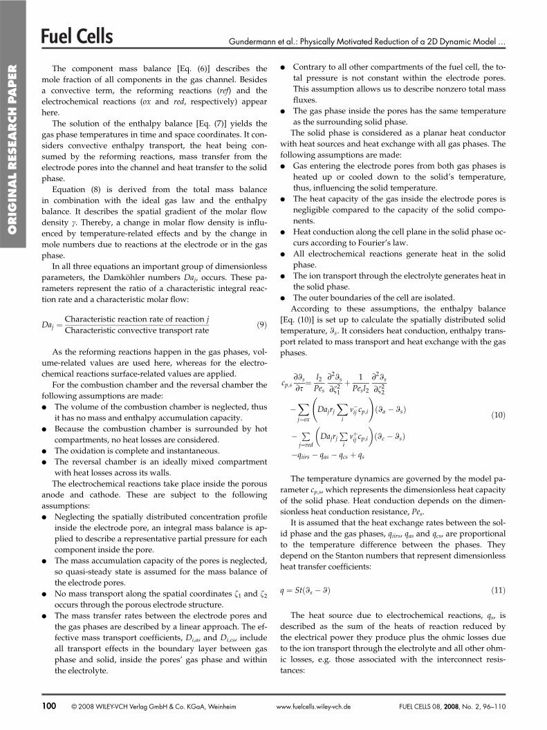
In order to highlight the reference model’s capabilities,Figures 3–6 show some selected simulation results of theMCFC model for an operating point with an average currentdensity of Icell = 80 mA cm�2. All other operating conditionsof this load are given in Table 1. This is a typical load case ofthe HotModule at the university hospital in Magdeburg, towhich the reference model was adjusted. The system wasoperated at a relatively low current density, but set a worldrecord with 30,000 h of operation. Typically, current densitiesin the HotModule are at about Icell = 120–160 mA cm�2. How-ever, the adjusted reference model showed good extra-polation properties, when measurements taken atIcell = 100 mA cm�2 agreed very well with the predictedbehaviour according to the model.
The spatial coordinates of the diagrams correspond to Fig-ure 2, where the flow directions are indicated. The simulationresults are compared to results from Heidebrecht and Sund-macher [3], where applicable.
In Figure 3, the indirect internal reformer is fed with fuelgas of a certain methane concentration that decreases alongthe channels due to the reforming reactions. At the outlet ofthe IIR (f1 = 0), approximately half of the methane is con-
Mol
e fr
actio
n x C
H4,
IIR /
%
Fig. 3 Steady-state mole fraction of methane in the IIR channels for a typical operat-ing point (Icell = 80 mA cm�2).
ORIG
INAL
RES
EARCH
PAPER
FUEL CELLS 08, 2008, No. 2, 96–110 © 2008 WILEY-VCH Verlag GmbH & Co. KGaA, Weinheim 101www.fuelcells.wiley-vch.de
Gundermann et al.: Physically Motivated Reduction of a 2D Dynamic Model ...
verted. As the fuel gas is fed into the IIR at a relatively lowtemperature, the reaction rates of the endothermic reformingreactions are very low in the beginning, which can be recog-nised by a flat profile at the IIR inlet (f1 = 1). But due to theheat exchange with the solid phase, the gas is heated upquickly and the reforming process is accelerated.
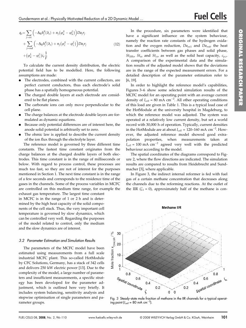
The anode channels are fed with the hydrogen-richexhaust gas from the IIR. This high educt concentrationenhances the oxidation reactions so that the hydrogenconcentration decreases rapidly (Figure 4). High reactionrates occur especially near the anode inlet (f1 = 0). The hydro-gen profiles in the individual channels are very similar,
but nevertheless small differences are visible. Onereason for this is the spatially distributed currentdensity. Furthermore, the reaction rates are differ-ent due to different temperatures within the chan-nels.
By including the IIR into the model, the hydro-gen profile looks completely different compared tothe simulation results of Heidebrecht [5]. Here theanode channels had been fed with a nonreformedgas, so that high reaction rates of the DIR and anincrease in the hydrogen concentration were ob-served at the anode inlet.
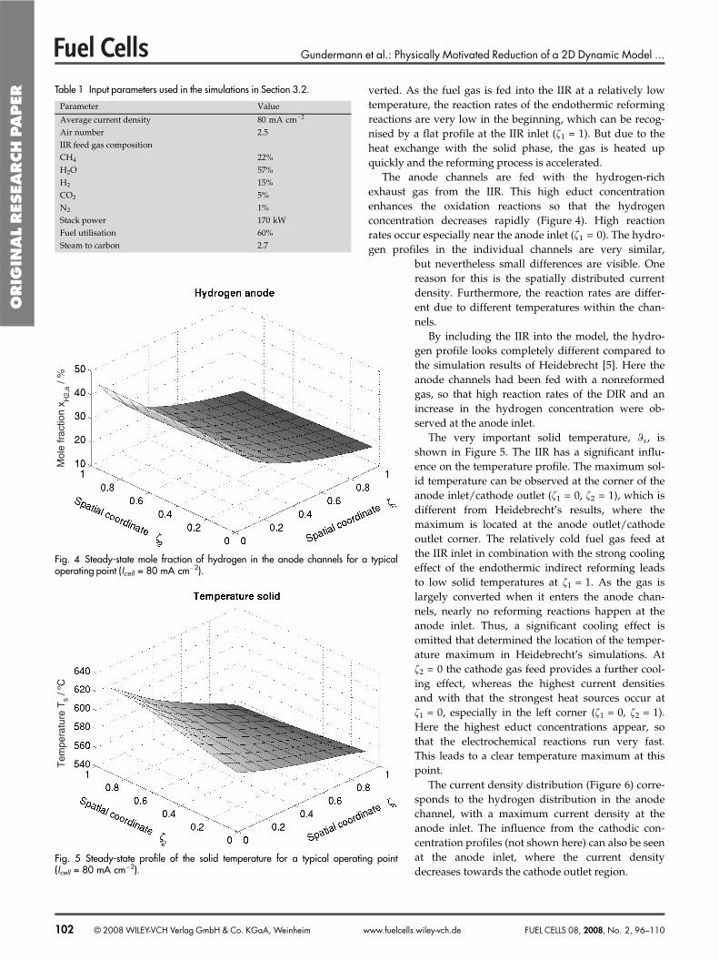
The very important solid temperature, �s, isshown in Figure 5. The IIR has a significant influ-ence on the temperature profile. The maximum sol-id temperature can be observed at the corner of theanode inlet/cathode outlet (f1 = 0, f2 = 1), which isdifferent from Heidebrecht’s results, where themaximum is located at the anode outlet/cathodeoutlet corner. The relatively cold fuel gas feed atthe IIR inlet in combination with the strong coolingeffect of the endothermic indirect reforming leadsto low solid temperatures at f1 = 1. As the gas islargely converted when it enters the anode chan-nels, nearly no reforming reactions happen at theanode inlet. Thus, a significant cooling effect isomitted that determined the location of the temper-ature maximum in Heidebrecht’s simulations. Atf2 = 0 the cathode gas feed provides a further cool-ing effect, whereas the highest current densitiesand with that the strongest heat sources occur atf1 = 0, especially in the left corner (f1 = 0, f2 = 1).Here the highest educt concentrations appear, sothat the electrochemical reactions run very fast.This leads to a clear temperature maximum at thispoint.
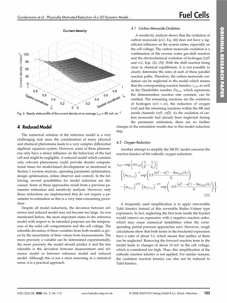
The current density distribution (Figure 6) corre-sponds to the hydrogen distribution in the anodechannel, with a maximum current density at theanode inlet. The influence from the cathodic con-centration profiles (not shown here) can also be seenat the anode inlet, where the current densitydecreases towards the cathode outlet region.
Mol
e fr
actio
n x H
2,a /
%
Fig. 4 Steady-state mole fraction of hydrogen in the anode channels for a typicaloperating point (Icell = 80 mA cm�2).
Tem
pera
ture
Ts
/ ºC
Fig. 5 Steady-state profile of the solid temperature for a typical operating point(Icell = 80 mA cm�2).
Table 1 Input parameters used in the simulations in Section 3.2.
Parameter Value
Average current density 80 mA cm�2
Air number 2.5IIR feed gas compositionCH4 22%H2O 57%H2 15%CO2 5%N2 1%Stack power 170 kWFuel utilisation 60%Steam to carbon 2.7
ORIG
INAL
RES
EARCH
PAPER
102 © 2008 WILEY-VCH Verlag GmbH & Co. KGaA, Weinheim FUEL CELLS 08, 2008, No. 2, 96–110www.fuelcells.wiley-vch.de
Gundermann et al.: Physically Motivated Reduction of a 2D Dynamic Model ...
4 Reduced Model
The numerical solution of the reference model is a verychallenging task since the consideration of many physicaland chemical phenomena leads to a very complex differentialalgebraic equation system. However, some of these phenom-ena only have a minor influence on the behaviour of the fuelcell and might be negligible. A reduced model which containsonly relevant phenomena could provide shorter computa-tional times for model-based developments as mentioned inSection 1 (system analysis, operating parameter optimisation,design optimisation, online observer and control). In the fol-lowing, several possibilities for model reduction are dis-cussed. Some of these approaches result from a previous pa-rameter estimation and sensitivity analysis. However, onlythose reductions are implemented that do not require a pa-rameter re-estimation as this is a very time-consuming proce-dure.
Despite all model reductions, the deviation between ref-erence and reduced model may not become too large. As wasmentioned before, the most important states in the referencemodel with respect to its intended purposes are the tempera-ture of the solid cell compartments and the cell voltage. Thetolerable deviation of these variables from both models is giv-en by the uncertainty of their values from measurements. Themore precisely a variable can be determined experimentally,the more precisely the model should predict it and the lesstolerable is the deviation between measurement and ref-erence model or between reference model and reducedmodel. Although this is not a strict reasoning in a statisticalsense, it is a practical approach.
4.1 Carbon Monoxide Oxidation
A sensitivity analysis shows that the oxidation ofcarbon monoxide [ox2, Eq. (4)] does not have a sig-nificant influence on the system states, especially onthe cell voltage. The carbon monoxide oxidation is acombination of the reverse water gas-shift reactionand the electrochemical oxidation of hydrogen [ref2and ox1, Eqs. (2), (3)]. With the shift reaction beingclose to chemical equilibrium, it is not possible toclearly determine the rates of each of these parallelreaction paths. Therefore, the carbon monoxide oxi-dation can be neglected in the model which meansthat the corresponding reaction kinetics, rox2, as wellas the Damköhler number Daox2, which representsthe dimensionless reaction rate constant, can beomitted. The remaining reactions are the oxidationof hydrogen (ox1 = ox), the reduction of oxygen(red) and the reforming reactions within the IIR andanode channels (ref1, ref2). As the oxidation of car-bon monoxide had already been neglected duringthe parameter estimation, there are no further
changes in the simulation results due to this model reductionstep.
4.2 Oxygen Reduction
Another attempt to simplify the MCFC model concerns thereaction kinetics of the cathodic oxygen reduction:
rred� exp Arrred1�r �
1�s
� �� �
�CO2�cc
� ��2exp 2�5
�Sc � �L
c � D�red�0 �s� �
�s
� �
� �O2�cc
� �0�75�CO2 �cc
� ��0�5exp �0�5
�Sc � �L
c � D�red�0 �s� �
�s
� ��
�13�
A frequently used simplification is to apply irreversibleTafel kinetics instead of this reversible Butler–Volmer typeexpression. In fact, neglecting the first term inside the bracketwould remove an expression with a negative reaction order,which may cause numerical instabilities when the corre-sponding partial pressure approaches zero. However, roughcalculations show that both terms in the bracketed expressionhave a ratio of about 3:1, which means that neither of themcan be neglected. Removing the forward reaction term in themodel leads to changes of about 10 mV in the cell voltage,which is considered too high. Thus, this simplification of thecathodic reaction kinetics is not applied. For similar reasons,the oxidation reaction kinetics can also not be reduced toTafel kinetics.
Cur
rent
den
sity
i m
Acm
-2
Fig. 6 Steady-state profile of the current density at an average Icell = 80 mA cm�2.
ORIG
INAL
RES
EARCH
PAPER
FUEL CELLS 08, 2008, No. 2, 96–110 © 2008 WILEY-VCH Verlag GmbH & Co. KGaA, Weinheim 103www.fuelcells.wiley-vch.de
Gundermann et al.: Physically Motivated Reduction of a 2D Dynamic Model ...
4.3 Reforming Reactions
After the parameter estimation, the Damköhler numbersof the reforming reactions (Daref1 and Daref2) were set to suffi-ciently high values to nearly attain chemical equilibrium inthe simulations. This might be a useful starting point for afurther model reduction step. If the assumption is made thatthe reforming reactions are in equilibrium, the reactionkinetics for the methane steam reforming (ref1) and thewater–gas shift reaction (ref2) as well as both Damköhlernumbers, Daref1 and Daref2, could be omitted. Instead of that,two new equations according to the law of mass action wouldbe required to describe the equilibria of the chemical reac-tions. In contrast to the reaction kinetics, these equationsimplicitly contain the reaction rates. This makes the numeri-cal solution much more difficult since the reaction rates aredetermined from polynomial functions that do not necessari-ly have a unique solution so that nonphysical results mightoccur.
Altogether the assumption of equilibrium for the reform-ing reactions does not lead to a better numerical solvability ofthe MCFC model and is therefore not appropriate for thismodel reduction.
4.4 Mass Transport Limitation
With a linear mass transport approach, the partial pressureof each component in the electrode pores, �i�ac and �i�cc, is cal-culated from the steady-state partial mass balance of the elec-trode pores:
�j�ox
mi�jDajrj � Di�as �i�ac � vi�a
� ��14�
�j�red
mi�jDajrj � Di�cs �i�cc � vi�c
� ��15�
In the reference model, the mass transport within the elec-trodes only plays a major role at high degrees of fuel utilisa-tion (above 85%), which are not applied in real systems.Therefore, the mass transport limitations might be negligibleunder moderate operating conditions. This simplification issupported by further arguments. Electrochemical processesin MCFC are usually limited by slow cathode reactionkinetics. This has been shown by Bednarz [14] on the sameelectrodes that are used in the HotModule. Furthermore, themass transport parameters could not be determined fromexperimental data from a HotModule plant. According to theprinciple of parsimonyb, those phenomena should beremoved from the model, whose relevance cannot be provenby experiments.
In this case, the mass transport coefficients have to be setas infinity:
Di�as→∞ Di�cs→∞ �16�
With this assumption the steady-state pore balances aresimplified to get:
�i�as � vi�a� �i�cs � vi�c �17�
Equation (17) can be directly inserted into the reactionkinetics. So, the partial pressures in the pores, �i�as and �i�cs,are eliminated and the reaction rates of the electrochemicalreactions directly depend on the gas concentrations in thechannels. Altogether the number of system states is reducedc
by 14 and the mass balances within the pores as well as thetwo parameters Di,as and Di,cs are no longer required.
The deviation of the cell voltage due to this model simplifi-cation is in the range of 1 mV for the investigated load casesat the HotModule. This is clearly smaller than the measure-ment error of the cell voltage and is therefore acceptable.However, the neglect of the mass transport limitation withinthe electrode pores significantly influences the temperaturedistribution within the cell. In particular, it causes an increasein the maximum solid phase temperature by approximately10 K.
The reason for that can be found in the electrochemicalreactions that run much faster at higher temperatures. Asmore heat is released by the reactions this process is self-accelerating. One major effect that counteracts to that is themass transport limitation. But if this is omitted, the cell tem-perature rises especially in the hot regions of the celld. A tem-perature increase by 10 K may seem large at first, but becauseit is limited to only a small region in the cell, its impact on theelectrochemical reaction kinetics and thereby on the cell volt-age is minimal. This temperature deviation must also be con-sidered with the fact in mind that direct measurement of thetemperature inside the cells is not possible. Therefore, anerror of 10 K is acceptable.
Due to these arguments, it is reasonable to neglect themass transport limitations for the time being. However, masstransport does play a role in cells with significantly highercurrent densities and will increasingly do so as current densi-ties in MCFC are increased. Thus, these processes are not gen-erally negligible, but must be investigated in more detail toobtain an appropriate description.
b Sometimes also referred to as Occam's Razor, for example see ref. [15].
c The partial pressures of seven components are calculated on the anode andcathode side.
d At high current densities and in consideration of a temperature-dependention conductivity of the electrolyte such effects can lead to thermal instabil-ities with multiple steady states and hot spots. Such phenomena had been in-vestigated for the first time by Mangold et al. [16] and they apply both toMCFC and SOFC.
ORIG
INAL
RES
EARCH
PAPER
104 © 2008 WILEY-VCH Verlag GmbH & Co. KGaA, Weinheim FUEL CELLS 08, 2008, No. 2, 96–110www.fuelcells.wiley-vch.de
Gundermann et al.: Physically Motivated Reduction of a 2D Dynamic Model ...
4.5 Charge Balances
The charging and discharging of the electric double layersis dominated by the fastest time constant of the model (seeSection 3.1), so that a quasi-steady state is reached after a fewmilliseconds. Due to this very small time constant, the investi-gation of these dynamic processes is not relevant for the pur-poses of this MCFC model.
However, from a numerical point of view there is noadvantage in using steady-state charge balances. The result-ing algebraic equations could only be solved with very goodinitial values which would cause serious problems whensimulating a load change. But regarding the equations for thepotential field, it is at least possible to assume that the currentdensities within the cell are equal after a very short period oftime:
ia � ie � ic � i �18�
This assumption can be used to simplify Eq. (12), fromwhich the heat source density qs is calculated. If the oxidationof carbon monoxide (ox2) is neglected (see Section 4.1) thisequation reads:
qs� �DRh0ox �s� �Daoxrox � DRh0
red �s� �Daredrred
�noxDaoxrox �Sa � �L
a � nredDaredrred �S
c � �Lc
� �L
a � �Lc
ieF
�19�
By inserting Faraday’s law, one obtains:
qs� �DRh0ox �s� � ia
noxF� DRh0
red �s� � � icnredF
� �
� iaF
�Sa � �L
a
� icF
�Sc � �L
c
� ieF
�La � �L
c
�20�
If all current densities are assumed to be equal [Eq. (18)]and it is defined that nred = nox = n = 2 the equation for qs canbe simplified as follows:
qs� iF
�DRh0ox �s� �
n��DRh0
red �s� �n
� �
� iF
�Sa � �L
a � �Sc � �L
c � �La � �L
c
� iF
1n
�DRh0ox �s� � � DRh0
red �s� � � �Sa � �S
c
� �
� iF
1n
�DRh0ox �s� � � DRh0
red �s� � � Ucell
� ��21�
If it is considered that the sum of the reaction enthalpies ofthe oxidation and reduction reactions corresponds to thecombustion enthalpy of hydrogen, the simplified equation forthe heat source density finally reads:
qs �iF
1n
�DCh0H2O �s� �
� �� Ucell
� ��22�
This simplification only influences the dynamic systembehaviour for a very short time during a stepwise loadchange. At the same time, the energy conservation is violatedtemporarily. But this model reduction has practically noinfluence on the medium-term (gas composition and gas tem-perature) and long-term (solid phase temperature) dynamics.Of course, the steady state of the system also does not change,because the applied simplifications are exactly true at steadystate. It is important to notice that the equations for the poten-tial field remain unchanged so that i≠ia≠ie≠ic still applies.Only for calculating the heat source density quasi-steady statecharge balances are assumed.
4.6 Electrolyte Resistance
Another possibility to simplify the equations of the electricpotential field is the assumption of a perfect ion conductivitywithin the electrolyte (je→∞), i.e. ohmic losses are neglected.But, such a modification of the MCFC model leads to signifi-cant changes in the simulation results, e.g. the cell voltage dif-fers up to 8 mV at steady-state operation. In order to compen-sate this deviation, a readjustment of the model parameters,especially the Damköhler numbers, is necessary. As this isnot desired here, the neglect of the electrolyte resistance isnot applied.
4.7 Balances Within the Gas Phases
The changes of the mole fractions, molar flows and tem-peratures within the gas phases of the HotModule happenwithin a few seconds such that after a short period of time aquasi-steady state is reached. These processes on a mediumtime scale (for time scales see Section 3.1) are important for aset-point control, which is already done using the cathodeexhaust gas temperature, for example. But for tracking con-trol, which is meant to shift the system from one load caseinto another one, only the slow system dynamics are relevant.For these purposes, not only the charge balances can beassumed to be in steady state but also the balances within thegas phases.
As already discussed for the charge balances, it is also use-ful here to still calculate these balances dynamically becausetheir treatment by numerics is easier than the steady stateequations. Nevertheless, the assumption of quasi-steady stategas phase balances can be used to simplify some of the modelequations.
Since the balance equations of all three gas phases are verysimilar, only the steady-state enthalpy balance of the anodegas phase [see Eq. (7)] is discussed here:
0 � �ca∂�a
∂f1��j�ox
Dajrj
�i m�ij cp�i�i vi�acp�i
��s � �a�
��
j�a�ref
�DRh0j �a� �
� � Dajrj�i vi�acp�i
� qas�i vi�acp�i
�23�
ORIG
INAL
RES
EARCH
PAPER
FUEL CELLS 08, 2008, No. 2, 96–110 © 2008 WILEY-VCH Verlag GmbH & Co. KGaA, Weinheim 105www.fuelcells.wiley-vch.de
Gundermann et al.: Physically Motivated Reduction of a 2D Dynamic Model ...
The steady-state enthalpy balances can be inserted into thetotal mass balances [Eq. (8)]. With this, all thermal expansioneffects are omitted and the equations can be simplified signif-icantly:
∂ca
∂f1��
j�a�ref
�mj Dajrj ��j�ox
�mj Dajrj �24�
From a numerical point of view, it is important that thedirect coupling between the gas temperature and the molarflow density is eliminated by this model reduction. Conse-quently, the system matrix is simplified and a better solvabil-ity of the model is achieved.
The simplification of the total mass balances has onlyminor influence on the dynamic system behaviour for a shortperiod of time. Thereby the conservation laws are violatedtemporarily. But, this modification of the model does notaffect the long-term temperature dynamics of the system (seeend of Section 3.1). Furthermore, the steady-state behaviourremains unchanged.
4.8 Heat Capacity
Within the reference model, component-related heat capa-cities are used to ensure the fulfilment of the energyconservation laws. Compared to the physically reducedmodel of Heidebrecht [5], where all components have a uni-form heat capacity, this requires a much higher numericaleffort since the heat capacity depends on the local concentra-tions and is therefore spatially distributed.
Although, the gas compositions in some compartments,e.g. in the anode channel, may change significantly along thegas flow direction, the heat capacity of the gas may still beassumed constant in each individual compartment of the fuelcell (IIR, anode, cathode and reversal chamber).
For the reversal chamber, which is assumed to be wellmixed, the heat capacity can be easily calculated by the mea-sured gas concentrations. Within the gas phases of the IIR,anode and cathode, the mole fractions are spatially distribu-ted which consequently leads to a spatially distributed heatcapacity. In this case, the chosen values correspond to themean values over the whole cell area, whereas several casesof load are considered.
Due to this model reduction the energy conservation isslightly violated but the resulting deviations in the simulationresults can be neglected. Compared to the reference model,the temperatures change by approximately 2 K and the dif-ference in the cell voltage is about 2 mV.
The application of constant heat capacities leads tochanges in a number of balance equations, which are theenthalpy balances and the total mass balances of the indirectinternal reformer, the anode and cathode channels, the com-bustion chamber and the reversal chamber. Within theseequations, the complex terms that calculate the heat capacity
(�
ivicp�i) are omitted so that nearly all dependencies on the
gas concentrations are eliminated. Only the temperaturechange in the gas phase still depends on the mole fractionsvia the reaction kinetics.
The enthalpy of the solid phase as well as the calculationof the reaction enthalpies remain unchanged by this simplifi-cation.
By using constant heat capacities, the model is only validfor load cases that have a similar concentration profile. Butfor the HotModule this is true for a wide range of operatingconditions.
4.9 Enthalpy Balance of the Solid Phase
Considering one oxidation and one reduction reaction, theenthalpy balance of the solid phase [Eq. (10)] reads as fol-lows:
cp�s∂�s
∂s� l2
Pes
∂2�s
∂f21� 1
Pesl2
∂2�s
∂f22��������������������������������������������
Heat conduction
�Daoxrox
�i
m�i�oxcp�i �a � �s� �����������������������������������������������������Mass transport anode�solid
�Daredrred
�i
m�i�redcp�i �c � �s� �������������������������������������������������������Mass transport cathode�solid
� qiirs � qas � qcs��������������������������Heat transfer gas phase�solid
�qs
�25�
The analysis of this equation shows that the individualterms have different orders of magnitude. It can be observedthat the direct heat exchange between the gas phases and thesolid phase as well as the heat sources due to the electro-chemical reactions have a much higher influence on the solidtemperature and their spatial distribution than the heat con-duction within the solid phase and the enthalpy transportwhich is related to the mass transport. Hence, a simplificationof the enthalpy balance seems to be possible.
If the heat conduction is neglected, the temperature profileremains nearly unchanged. The maximum solid temperaturediffers by 3–4 K and the minimum temperature only changesby approximately 3 K. Furthermore, the cell voltage onlyshows a small deviation of about 0.1 mV. As the simulatedtemperature profile cannot be compared to measurements atthe real fuel cell, it is not possible to determine the heat con-duction resistance represented by the Peclet number Pes.Therefore, it seems to be appropriate to neglect the heat con-duction term in the enthalpy balance of the solid phase whichleads to the following equation:
cp�s∂�s
∂s� �Daoxrox
�i
m�i�oxcp�i �a � �s� �
�Daredrred
�i
m�i�redcp�i �c � �s� �
�qiirs � qas � qcs � qs
�26�
ORIG
INAL
RES
EARCH
PAPER
106 © 2008 WILEY-VCH Verlag GmbH & Co. KGaA, Weinheim FUEL CELLS 08, 2008, No. 2, 96–110www.fuelcells.wiley-vch.de
Gundermann et al.: Physically Motivated Reduction of a 2D Dynamic Model ...
Due to this simplification the type of equation changesfrom parabolic partial differential equation (PDE) to ordinarydifferential equation (ODE). The local temperature within thesolid phase no longer depends on the temperatures in thedirect neighbourhood but is only determined by the localreaction rates and the heat exchange with the gas phases. Inthe discretised form of the model this means that the systemmatrix loses some minor diagonals, which simplifies thenumerical treatment. Heat exchange between differentregions of the solid phase only happens indirectly via the gasphases. Overall, this means a significant simplification of thesystem matrix and an easier numerical treatment of themodel.
Besides heat conduction, the influence of the enthalpytransport that is related to the mass transport on the solidtemperature is also very low. With the help of Faraday’slaw the term for the molar flow between anode gas andsolid phase can be estimated for a typical load case of theHotModule (Icell = 80 mA cm�2 or dimensionless i = 0.45) asfollows:
Daoxrox
�i
m�i�oxcp�i �a � �s� � � inoxF
mH2�oxcp�H2�a � �s� �
� �1�86 �a � �s� ��27�
This can be compared to the direct heat exchange betweenanode gas and solid:
qas � Stas �s � �a� � � �40�0 �a � �s� � �28�
The ratio of both values is about 1:20 which means that theenthalpy transport related to mass transport is much smallerthan the direct heat exchange. A similar result can beobtained for the cathode side of the cell, where the ratio isapproximately 1:30.
However, the neglect of both terms leads to a seriousdeviation of the simulated cell voltage of approximately5 mV. At first glance one would expect that this error couldbe corrected by a slight change of the Stanton numbers. Forexample, according to the estimation above an increase in theparameter Stas from 40.0 to 42.0 should be a compensation.Unfortunately, it is not possible to reach the original cell volt-age by this means as can be seen in Table 2.
The reason for this result is the fact that the Stanton num-bers affect the whole cell area uniformly, whereas the thermaleffects strongly depend on the local current densities. Thismeans that enthalpy transport related to mass transport ishigher in the hot corners where the reactions run very fast.Therefore, the neglect of the corresponding terms of the
enthalpy balance cannot be compensated by a slight changeof the Stanton numbers. Instead, an extensive readjustment ofthe model parameters would be necessary which is not desir-able.
5 Results
In the previous chapter, nine possible reduction steps ofthe detailed MCFC model have been discussed. But onlythose changes are applied that only show small deviationsfrom the reference model and do not demand a re-adjustmentof the model parameters. Table 3 gives an overview of all dis-cussed model reductions and their impact on the steady-statesimulation results regarding the cell voltage and the tempera-ture field.
Six model reductions are applied. Their impact on themajor equations from Section 3.1 can be seen in the following.The simplified gas phase balances are exemplarily given forthe anode channels [see Eqs. (6)–(8)]. They read:
Va
�a
∂vi�a
∂s� �ca
∂vi�a
∂f1� mi�ox � vi�a �mox
� �Daoxrox
��
j�a�ref
mi�j � vi�a �mj
� �Dajrj
�29�
Va
�a
∂�a
∂s� �ca
∂�a
∂f1��
j�a�ref
�DRhhj �a� �
� �Dajrj
cp�a
�Daoxrox �m�ox ��s � �a� � qas
cp�a
�30�
∂ca
∂f1��
j�a�ref
�mj Dajrj � �mox Daoxrox �31�
Table 2 Influence of the enthalpy transport related to mass transport onthe cell voltage for a selected load case (Icell = 80 mA cm�2).
EB with mass transport Stas Stcs Ucell / mV DUcell / mV
Yes 40 138 789.1 –No 40 138 793.5 4.4No 42 142 793.3 4.1
Table 3 Possible reductions of the MCFC model and the correspondingdeviations in simulation results.
Simplification Applied Model deviation at steady stateDUcel / mV DTs,max / K DTs,min / K
Oxidation of COneglected
Yes 0 0 0
Irreversible cathodereaction
No ≈10 >20 ≈5
Steady-state reformingreactions
No – – –
Mass transportlimitation neglected
Yes ≈1 ≈10 ≈1
Identical currentdensities in qs
Yes (No influence on steady state)
Electrolyte resistanceneglected
No ≈8 ≈2 ≈5
Thermal gas expansionneglected
Yes (No influence on steady state)
Constant heat capacities Yes ≈2 ≈1 ≈2Heat conductionneglected
Yes ≈0.1 ≈4 ≈3
ORIG
INAL
RES
EARCH
PAPER
FUEL CELLS 08, 2008, No. 2, 96–110 © 2008 WILEY-VCH Verlag GmbH & Co. KGaA, Weinheim 107www.fuelcells.wiley-vch.de
Gundermann et al.: Physically Motivated Reduction of a 2D Dynamic Model ...
The enthalpy balance of the solid phase changes signifi-cantly compared to Eqs. (10) and (12):
cp�s∂�s
∂s� �Daoxrox �m
�ox cp�a �a � �s� �
�Daredrred �m�red cp�c �c � �s� �
�qiirs � qas � qcs � qs
�32�
where
qs � iF
1n
�DRhhox �s� � � DRhh
red �s� � � Ucell
� ��33�
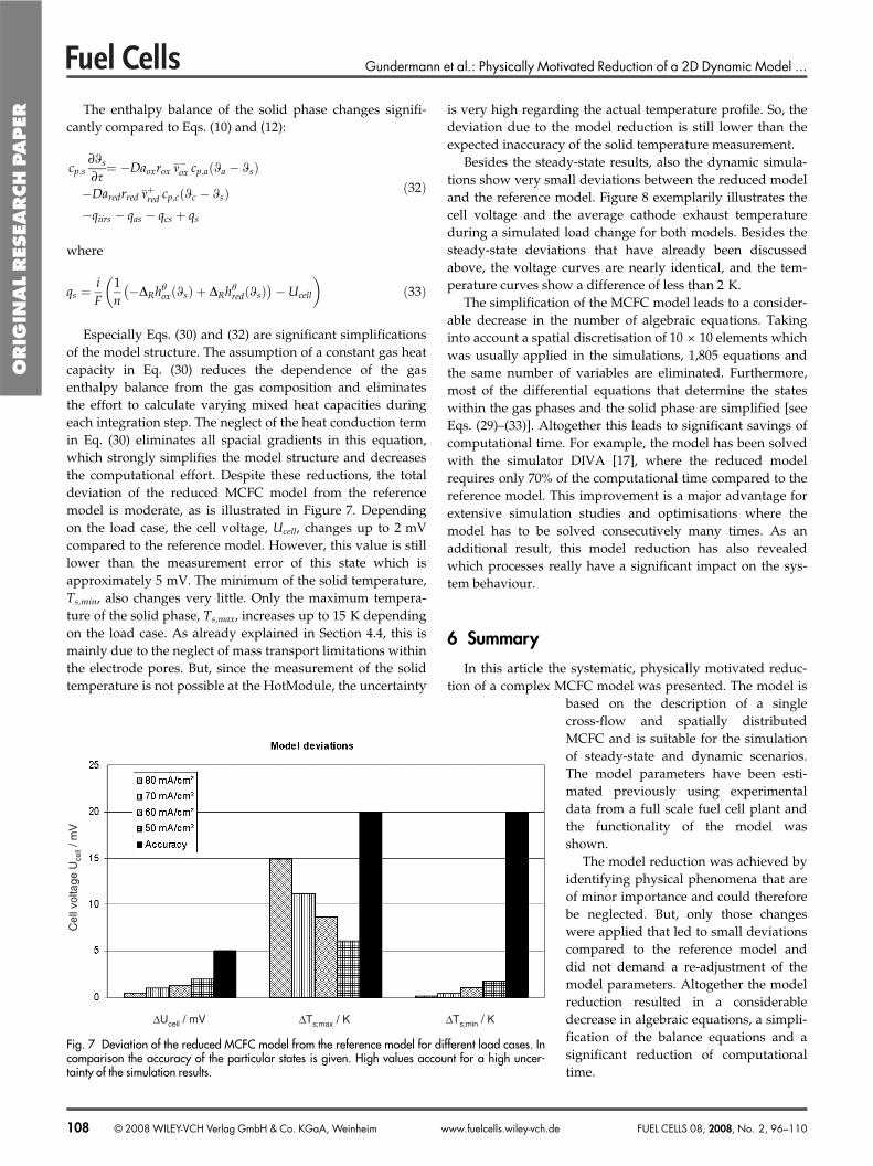
Especially Eqs. (30) and (32) are significant simplificationsof the model structure. The assumption of a constant gas heatcapacity in Eq. (30) reduces the dependence of the gasenthalpy balance from the gas composition and eliminatesthe effort to calculate varying mixed heat capacities duringeach integration step. The neglect of the heat conduction termin Eq. (30) eliminates all spacial gradients in this equation,which strongly simplifies the model structure and decreasesthe computational effort. Despite these reductions, the totaldeviation of the reduced MCFC model from the referencemodel is moderate, as is illustrated in Figure 7. Dependingon the load case, the cell voltage, Ucell, changes up to 2 mVcompared to the reference model. However, this value is stilllower than the measurement error of this state which isapproximately 5 mV. The minimum of the solid temperature,Ts,min, also changes very little. Only the maximum tempera-ture of the solid phase, Ts,max, increases up to 15 K dependingon the load case. As already explained in Section 4.4, this ismainly due to the neglect of mass transport limitations withinthe electrode pores. But, since the measurement of the solidtemperature is not possible at the HotModule, the uncertainty
is very high regarding the actual temperature profile. So, thedeviation due to the model reduction is still lower than theexpected inaccuracy of the solid temperature measurement.
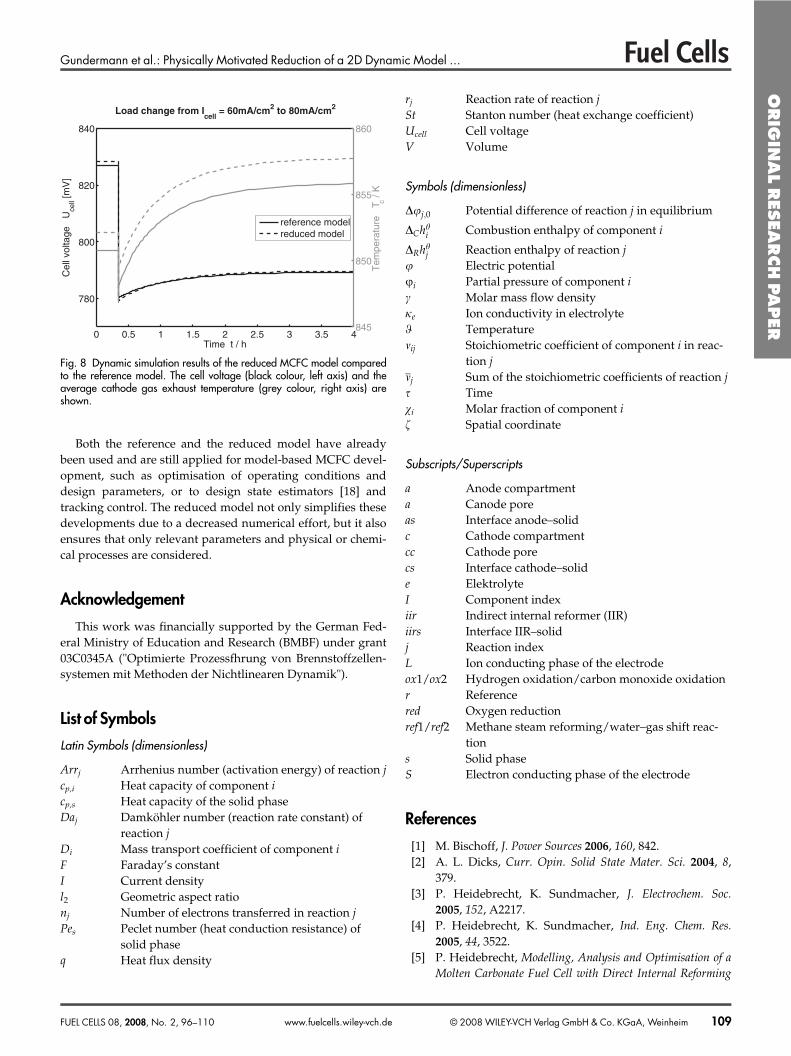
Besides the steady-state results, also the dynamic simula-tions show very small deviations between the reduced modeland the reference model. Figure 8 exemplarily illustrates thecell voltage and the average cathode exhaust temperatureduring a simulated load change for both models. Besides thesteady-state deviations that have already been discussedabove, the voltage curves are nearly identical, and the tem-perature curves show a difference of less than 2 K.
The simplification of the MCFC model leads to a consider-able decrease in the number of algebraic equations. Takinginto account a spatial discretisation of 10 × 10 elements whichwas usually applied in the simulations, 1,805 equations andthe same number of variables are eliminated. Furthermore,most of the differential equations that determine the stateswithin the gas phases and the solid phase are simplified [seeEqs. (29)–(33)]. Altogether this leads to significant savings ofcomputational time. For example, the model has been solvedwith the simulator DIVA [17], where the reduced modelrequires only 70% of the computational time compared to thereference model. This improvement is a major advantage forextensive simulation studies and optimisations where themodel has to be solved consecutively many times. As anadditional result, this model reduction has also revealedwhich processes really have a significant impact on the sys-tem behaviour.
6 Summary
In this article the systematic, physically motivated reduc-tion of a complex MCFC model was presented. The model is
based on the description of a singlecross-flow and spatially distributedMCFC and is suitable for the simulationof steady-state and dynamic scenarios.The model parameters have been esti-mated previously using experimentaldata from a full scale fuel cell plant andthe functionality of the model wasshown.
The model reduction was achieved byidentifying physical phenomena that areof minor importance and could thereforebe neglected. But, only those changeswere applied that led to small deviationscompared to the reference model anddid not demand a re-adjustment of themodel parameters. Altogether the modelreduction resulted in a considerabledecrease in algebraic equations, a simpli-fication of the balance equations and asignificant reduction of computationaltime.
Cel
l vol
tage
Uce
ll / m
V
∆Ucell / mV ∆Ts;max / K ∆Ts;min / K
Fig. 7 Deviation of the reduced MCFC model from the reference model for different load cases. Incomparison the accuracy of the particular states is given. High values account for a high uncer-tainty of the simulation results.
ORIG
INAL
RES
EARCH
PAPER
108 © 2008 WILEY-VCH Verlag GmbH & Co. KGaA, Weinheim FUEL CELLS 08, 2008, No. 2, 96–110www.fuelcells.wiley-vch.de
Gundermann et al.: Physically Motivated Reduction of a 2D Dynamic Model ...
Both the reference and the reduced model have alreadybeen used and are still applied for model-based MCFC devel-opment, such as optimisation of operating conditions anddesign parameters, or to design state estimators [18] andtracking control. The reduced model not only simplifies thesedevelopments due to a decreased numerical effort, but it alsoensures that only relevant parameters and physical or chemi-cal processes are considered.
Acknowledgement
This work was financially supported by the German Fed-eral Ministry of Education and Research (BMBF) under grant03C0345A ("Optimierte Prozessfhrung von Brennstoffzellen-systemen mit Methoden der Nichtlinearen Dynamik").
List of Symbols
Latin Symbols (dimensionless)
Arrj Arrhenius number (activation energy) of reaction jcp,i Heat capacity of component icp,s Heat capacity of the solid phaseDaj Damköhler number (reaction rate constant) of
reaction jDi Mass transport coefficient of component iF Faraday’s constantI Current densityl2 Geometric aspect rationj Number of electrons transferred in reaction jPes Peclet number (heat conduction resistance) of
solid phaseq Heat flux density
rj Reaction rate of reaction jSt Stanton number (heat exchange coefficient)Ucell Cell voltageV Volume
Symbols (dimensionless)
D�j�0 Potential difference of reaction j in equilibrium
DChhi Combustion enthalpy of component i
DRhhj Reaction enthalpy of reaction j
� Electric potential�i Partial pressure of component ic Molar mass flow densityje Ion conductivity in electrolyte� Temperaturemij Stoichiometric coefficient of component i in reac-
tion jmj Sum of the stoichiometric coefficients of reaction js Timevi Molar fraction of component if Spatial coordinate
Subscripts/Superscripts
a Anode compartmenta Canode poreas Interface anode–solidc Cathode compartmentcc Cathode porecs Interface cathode–solide ElektrolyteI Component indexiir Indirect internal reformer (IIR)iirs Interface IIR–solidj Reaction indexL Ion conducting phase of the electrodeox1/ox2 Hydrogen oxidation/carbon monoxide oxidationr Referencered Oxygen reductionref1/ref2 Methane steam reforming/water–gas shift reac-
tions Solid phaseS Electron conducting phase of the electrode
References
[1] M. Bischoff, J. Power Sources 2006, 160, 842.[2] A. L. Dicks, Curr. Opin. Solid State Mater. Sci. 2004, 8,
379.[3] P. Heidebrecht, K. Sundmacher, J. Electrochem. Soc.
2005, 152, A2217.[4] P. Heidebrecht, K. Sundmacher, Ind. Eng. Chem. Res.
2005, 44, 3522.[5] P. Heidebrecht, Modelling, Analysis and Optimisation of a
Molten Carbonate Fuel Cell with Direct Internal Reforming
0 0.5 1 1.5 2 2.5 3 3.5 4
780
800
820
840
Time t / h
Cel
l vol
tage
U
cell [m
V]
845
850
855
860
Load change from Icell
= 60mA/cm2 to 80mA/cm2
Tem
pera
ture
T c /
K
reference modelreduced model
Fig. 8 Dynamic simulation results of the reduced MCFC model comparedto the reference model. The cell voltage (black colour, left axis) and theaverage cathode gas exhaust temperature (grey colour, right axis) areshown.
ORIG
INAL
RES
EARCH
PAPER
FUEL CELLS 08, 2008, No. 2, 96–110 © 2008 WILEY-VCH Verlag GmbH & Co. KGaA, Weinheim 109www.fuelcells.wiley-vch.de

Gundermann et al.: Physically Motivated Reduction of a 2D Dynamic Model ...
(DIR-MCFC), Fortschritt-Berichte, VDI-Verlag, Düssel-dorf, 2005, 11.
[6] K. Sundmacher, A. Kienle, H. J. Pesch, J. F. Berndt,G. Huppmann (Eds.), Molten Carbonate Fuel Cells, Wi-ley-VCH, Weinheim, 2007.
[7] M. Mangold, M. Grötsch, M. Sheng, A. Kienle in Controland Observer Design for Nonlinear Finite and Infinite Di-mensional Systems (Eds. T. Meurer, K. Graichen, E. D.Gilles), Springer, Berlin, 2005, pp. 93.
[8] G. H. J. Broers, J. A. A. Ketelaar, Ind. Eng. Chem. 1960,52, 303.
[9] J. A. A. Ketelaar in Fuel Cell Systems (Eds. L. J. M. J. Blo-men, M. N. Mugerwa), Plenum Press, New York, 1993,pp. 19.
[10] B. Bosio, P. Costamagna, F. Parodi, Chem. Eng. Sci. 1999,54, 2907.
[11] M. Fermeglia, A. Cudicio, G. DeSimon, G. Longo,S. Pric, Fuel Cells 2005, 5, 66.
[12] M. Gundermann, Ph.D. Thesis, Otto-von-Guericke-Uni-versity Magdeburg, Magdeburg, Germany, 2007.
[13] M. Bischoff, G. Huppmann, J. Power Sources 2002, 105,216.
[14] M. Bednarz, Ph.D. Thesis, IPCH University, Hamburg,2002.
[15] H. Akaike, IEEE Trans. Autom. Contr. 1974, 6, 719.[16] M. Mangold, M. Krasnyk, K. Sundmacher, J. Appl. Elec-
trochem. 2006, 36, 265.[17] R. Köhler, K. Mohl, H. Schramm, M. Zeitz, A. Kienle,
M. Mangold, E. Stein, E. D. Gilles in Adaptive Method ofLines (Eds. A. Vande Wouver, P. Saucez, W. Schiesser),Chapman & Hall/CRC Press, Boca Raton, 2001, pp. 371.
[18] M. Grötsch, M. Gundermann, M. Mangold, A. Kienle,K. Sundmacher, J. Process Control 2006, 16, 985.
[19] M. Grundermann, P. Heidebrecht, K. Sundmacher, Ind.Eng. Chem. Res., in press.
______________________
No need to waste
precious time looking
for the right information
– Register now for the
free Wiley-VCH Alerting Service.
Life‘s Simple Pleasures!
To receive regular news per e-mail tailored precisely to your needs and interests, just fi ll in the registration form at www.wiley-vch.de/home/pas/
It‘s simple – and it‘s fast.
1328
0407
_gu
ORIG
INAL
RES
EARCH
PAPER
110 © 2008 WILEY-VCH Verlag GmbH & Co. KGaA, Weinheim FUEL CELLS 08, 2008, No. 2, 96–110www.fuelcells.wiley-vch.de