physics 2 - lapin amkweb.lapinamk.fi/jouko.teeriaho/physics2/ph2theory.pdf · faraday cage ....
TRANSCRIPT
1
Physics 2
Jouko Teeriaho
Rovaniemi UAS
Main objective
• Understanding the basic phenomena and
laws of electricity, magnetism and
electromagnetic waves
Material:
* Giancoli: Physics for Engineers and Scientist
* Other material: Dr. Lewin’s video lectures for MIT students

2
Assessment criteria
• Assignments
• 2 exams
• Concepts of electrostatics
– Charge, current, electric force, induction
– Electric fields, potential, voltage
• Resistance and resistors
• Capacitance and capacitors
• Batteries
Part 1
Part 2
• Magnetic force
• Magnetic field
• Magnetic induction, coils, generators
• Transformers, 3 phase current, electric network
• AC
• Electromagnetic waves

3
Basic
Phenomena
and history
Ancient Greece:
• People observed that when one rubs amber, it starts to attract light bodies (in Greek language “electron” means amber)
• Later was found: If you rub glass with fur, it also attracts light bodies
* Two rubbed glass sticks repel each other, two amber sticks repel each other but glass and amber attract each other.
There are two kinds of electricity: +
and -
An American physicist, politician and writer Benjamin Franklin (1706-1790) suggested that there is only one kind of “electric fire”, which we call electric charge.
Negative charge is excess of electrons
positive charge is lack of electrons
History:
Amber
Benjamin Franklin 1706 -1790
US writer, politician, scientist,
inventor, civil activist, diplomat

4
Atoms a held together by electricity
+
Nucleus:
Protons:
mass mp = 1.7*10-27 kg
charge q = 1.6*10-19 C
Neutrons:
mass mn equals proton mass
charge q = 0 (neutral)
-
electrons
mass = protonmass/1830
charge q = -e =-1.6*10-19 C
Electric charge is quantized : all charges are multiples of the electron charge Q = n*e
10-12 m
10-8m
Conductors and non-conductors
Charge (typically electrons) can move freely in a conductor. Metals are good conductors.
In a non-conductor charges are not free. They are bound to atoms and cannot move along the non-conductor.
Copper is an excellent conductor
Plastic, rubber and glass are
non-conductors

5
Electric current I
* Electric current is defined as motion of electric charge
• In most cases charge is carried by electrons, sometimes ions
• Symbol of charge is Q and units 1 C = 1 Coulomb
• Smallest charge is electron charge -1.6*10-19 C
• 1 Ampere is 1 Coulomb per second
• the direction of current is opposite to the direction of electron stream
current I electrons
Q = I t charge = current x time
1 C = 1 As (“AmpereSecond”)
Three interactions of Physics
Gravitation hold the universe together
Electric force keeps the atoms together
Nuclear force keeps the nuclei of atoms together

6
Electric force
2
21
r
QQkF
1736 - 1806
The French Andre Coulomb observed, that the force between two charges is proportional to the charges and inversely proportional to the square of their distance
k = 9.0*109 Nm2/C2 = Coulombs constant
04
1
k
k can be expressed in terms of 0 , which is called vacuum permittivity
0 = 8.85*10-12 C2/Nm2
Coulomb’s law
Vector form of Coulomb’s law
rr
QQkF ˆ
2
21 q1 q2
r̂where is the unit vector from q1 to q2.
F F
* If charges have the same polarity (= sign
of charge ), the force is repulsive.
* If the charges have different polarities , the
force is attractive

7
Superposition principle
The total force due to several charges q1,q2,… on a
charge Q is the vector sum of the forces due to the individual charges.
q1
q2
+
_
+Q
F
F1
F2
)180cos(2 21
2
2
2
1 FFFFF
If is the angle between vectors F1 andF2, the sum vector is
Electric induction
Charged
rod
-
-
-
+
+
+
Induction = division of charge in conductor due to an external charge. In the picture + charge attracts free electrons, and the right side of the conductor gets a positive layer
* A charged body attracts light pieces of conductor, because of the different
distances to the induced layers in the conductor.
-q +q
+Q

8
Polarization of atoms at the presence
of external charge
symmetric atom atom polarized by induction
+ + -
external
charge
nuclei and electrons move to different directions =>
atom becomes a dipole with two electric poles
-Q
Induction appears also in non-conductors
External charge causes polarization => there will be thin charged layers on both sides of the non-conductor
A charged body attracts slightly non-conductors ( rubber balloon)
-Q + + + + + + + + + +
+ + + + + + + + + +
+ + + + + + + + + +
- - - - - - - - - -
- - - - - - - - - -
- - - - - - - - - -
thin charged layers

9
Electroscope indicates charge
+
+ +
Metal rod Light Aluminum rod
Charged rod
+Q
Charge moves into the electroscope from the charged rod. Repulsion force makes the
Aluminum leaf rise and form an angle with the electroscope rod. This means that the
electroscope was charged.
Electric field E
Q q
Positive test charge
F
P
Electric field at point P is defined q
FE
Electric field = electric force / charge
Unit = 1 N/C , which equals 1 V/m as later shown
10
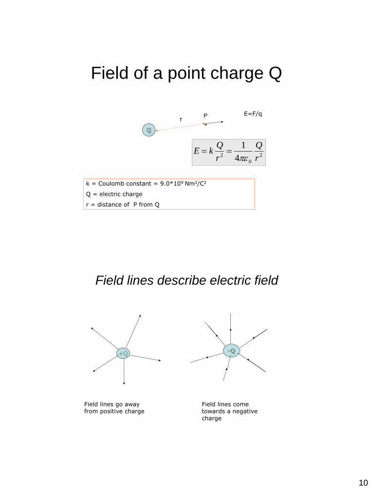
Field of a point charge Q
Q
E=F/q
2
0
2 4
1
r
Q
r
QkE
r
k = Coulomb constant = 9.0*109 Nm2/C2
Q = electric charge
r = distance of P from Q
P
Field lines describe electric field
+Q -Q
Field lines go away from positive charge
Field lines come towards a negative charge

11
Two charge system field lines
Dipole field Two positive charges
Field lines start from positive pole
and bend towards the negative
pole
Field lines bend as if they would
“repel” each other
Homogenous electric field
Charged cloud + + + + + + + + + + + + + + + + + + + + + + + + +
- - - - - - - - - - - - - - - - - - - - - - - - - - -
Electric field E
Friction of the motion of air layers charges the cloud. Induction attracts an equal, opposite
charge to the ground. Field lines are parallel and the field is uniform.
Breakdown voltage of air is 3 MV/m. When the field exceeds it, electrons are removed from
their host atoms and lightning starts.
Ground

12
Conductor in an electric field
1) Inside the conductor electric field becomes zero
2) Field lines penetrate the surface in 90 o angle
Charge distribution in a conductor
+ +
+
+
+ +
+ +
It can be shown that the charge density and electric field is greatest at the edges of a conductor.
The sharper the edge, the bigger field and charge density
E
E = 0

13
Figure: conductors in electric field
Electrostatic Induction:
Electrons move inside the
conductor to new positions:
1. The electric field inside the
conductor becomes zero
2. Field lines penetrate the
conductor surface in straight
angles.
Faraday cage
Faraday cage is made of metal.
Inside the cage electric field = 0
regardless of outside fields.
Faraday cage is a shield
against static fields and low
frequency alternating fields (Long Wave radio is not heard
inside)
High frequency GSM field can
penetrate into the cage
Car is a good shelter during
lightning of a thunderstorm
Link: MIT-video on Faraday cage

14
Non conductor in an E-field
-
-
-
-
-
+
+
+
+
+
+
+
+
+
+
+
-
-
-
-
-
-
E is weakened in the nonconductor due to atomic polarization
Field is weakened by factor which is called the dielectric
constant or relative permittivity of the of the material
Eint Eext
For paper = 3 , rubber = 7, glass = 7 , water = 80
extE
E int
Motion due to the electric force
According to Newtons law F = ma = qE =>
Em
qa
Positive charge ”falls” in the direction of
field lines
The trajectory is a parabola as in the free fall under gravity
trajectory E
F = q E
15
+ + + + + + +
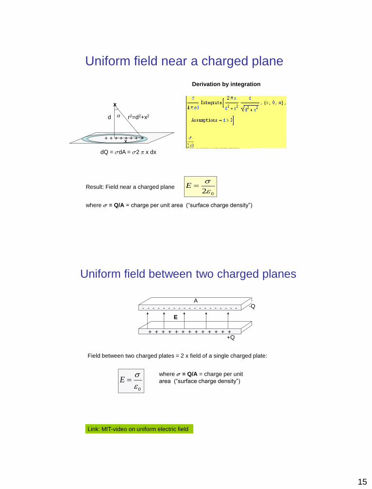
Uniform field near a charged plane
dQ = dA = 2 x dx
02
E
where = Q/A = charge per unit area (“surface charge density”)
x
x
d r2=d2+x2
Derivation by integration
Result: Field near a charged plane
Uniform field between two charged planes
+ + + + + + + + + + + + +
- - - - - - - - - - - - - - - - - - - -Q
+Q
A
E
Field between two charged plates = 2 x field of a single charged plate:
0
E
where = Q/A = charge per unit
area (“surface charge density”)
Link: MIT-video on uniform electric field

16
Potential V
Voltage U
Definition of potential V
Potential of point P = work per unit charge needed to bring a positive test charge from infinity to P
q
WV unit J/C = 1 V (Volt)
Voltage means difference of potentials of points A and B.
Voltage is thus the potential energy difference per unit charge
U = VB - VA
17
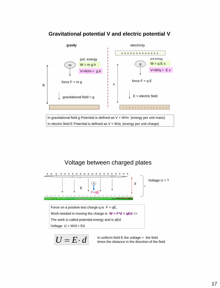
Gravitational potential V and electric potential V
m
h
gravitational field = g
force F = m g
q
- - - - - - - - - - - - - - -
x
E = electric field
force F = q E
+ + + + + + + + + + + + +
W = m g h W = q E x
V=W/m = g h V=W/q = E x
In gravitational field g Potential is defined as V = W/m (energy per unit mass)
In electric field E Potential is defined as V = W/q (energy per unit charge)
gravity electricity
m
h
gravity
pot. energy pot.energy
Voltage between charged plates
+ + + + + + + + + + + + + + + + + + + + +
- - - - - - - - - - - - - - - - - - - - - -
E
d Voltage U = ?
Force on a positive test charge q is F = qE,
Work needed in moving the charge is W = F*d = qEd =>
The work is called potential energy and is qEd.
Voltage U = W/d = Ed
+
F=qE
dEU In uniform field E the voltage = the field
times the distance in the direction of the field

18
Potential of a point charge
2r
QkE
r
Qqdr
r
QqdrqEW
rP
P
0
2
0 4.
4.
Q V = 0
r
Work needed to bring +q :n to point P is
Division by q gives
r
QrV
04)(
Potential of a point P at distance r from point charge Q
Piste P
Potential on the surface and inside the sphere is 90kV
Outside the sphere potential decreases proportional to 1/r
Figure shows electric potential inside and outside of a charged metal sphere with Q = 1 Coulomb and r = 0.10 m
90 kV
Link: MIT-video on a light tube in a field of a charged sphere

19
Energy principle in
electric field:
Application: TV - tube
TV - tube
When electrons are accelerated using voltage U, the potential energy is transformed to kinetic energy
2
21 mvqU
TV tube formula

20
In TV –tube electrons are accelerated using 3.0 kV voltage. Calculate their final speed when hitting the screen.
Electron’s charge and mass are 1.6*10-19 C and 9.11*10-31 kg
Electron being very light is easy accelerated. If the accelerating voltage is tens of hundreds kiloVolts like in X-ray tube, we cannot use classical formula ½ mv2 for kinetic energy. Then the equation must be replaced by
2
21 mvqU sm
m
Uqv /
1011.9
3000106.12231
19
=>
= 3.24621×107 = 32 Mm/s ( 10% of the speed of light)
22
2
2
1mc
mcqU
c
v
where c = the speed of light 300 Mm/s
In this Einstein’s formula m = the mass at rest, m/(1-v2/c2) is
the increased kinetic mass in the speed of v.
2
21
r
QQkF
q
FE
2
21 mvqU
Q = I t
dEU
q
WV
pot
U = VB - VA
Summary of formulas of electrostatics
Charge and current
Electric force
Electric field
Electric potential
Voltage between points A and B
Voltage in a uniform field
TV tube formula
2r
QkE Electric field of a point charge
Electric potential around a point charge r
QkV
UqW Potential energy difference

1
DC circuits
• Resistance, resistors
• Batteries
• DC circuits
Direct Current = DC
In TV tube the electric potential energy is transformed into kinetic energy
according to q U = ½ m v2
Resistance
wire
heat
+ -
In a wire the electrons collide with atoms and all the electric potential energy is
transformed into thermal energy
Created heating power
UIt
qU
t
EP
pot

2
Ohm’s law
Denote l = length. A = cross area of a wire, U = voltage and I = current in the wire.
It can be shown that voltage and current are linearly dependent : U = RI. Coefficient R depends on length l, cross area A, density of free electrons n, and mean time between collisions T.
RIIA
lI
A
l
nTeU
2
1
Parameters n, T are properties of the material. They determine a quantity .
= resistivity of the material , unit m (Ohmmeter)
Resistance unit
1 = 1 Ohm
e = electron charge
Ohm’s law
U = R I Ohm’s law
A
lR
= resistivity of material
l = length of wire
A = cross area of wire
Resistance R depend on following parameters:
Copper Cu 1.7 ( 10-8 m)
Iron Fe 9.7
Silver Ag 1.6
Tin Sn 11
Carbon C 1000
Table of resistivities
of common conductors

3
Resistors
Resistors are common components in electronics
Heating resistors are used in grills, electric heaters.
Combining P = U I and U = RI we get three different formulas for
power consumed in a resistor
R
URIUIP
22
Power
consumption
W = P t Energy consumed
in time t
linkki
Examples
Ex 1: Calculate the resistance of 100 km long 2.0 cm thick Copper wire
4.5)(*
100000107.1
2
202.0
8
A
lR
Ex 2: How much current uses a 1200 W car heater, which uses 220 V AC.
P = U I => I = P / U = 1200 W / 220 V = 5.5 A
Ex 3: Calculate the cost when 600 W car heater is used 12 h per day during January (unit price of electricity is 10 cnt/kWh)
Energy used = 0.6 kW * 31*12 h = 223 kWh
Cost = 22 Euro

4
More examples
242000
)220( 22
W
V
P
UR
Ex 4: Calculate a) resistance of a 6.0 kW electric sauna b) resistance of 2000 W electric cooker?
Ex 5: How many 12 Ampere fuses is needed for the 6 kW sauna, if the 220 V AC is used.
1.86000
)220( 222
W
V
P
UR
R
UPSauna
Cooker
Current I = P / U = 6000W / 220V = 27.3 A
=> Sauna needs 3 fuses
Resistor symbol 10
Resistors in series
R2 R1
U I
U1 U2
R I = R1 I + R2 I
R = R1 + R2 + …
or
Total voltage U is divided to U1 and U2.
U = U1 + U2
By Ohm’s law this becomes
where R = total resistance of the system
Dividing I we get
2
1
2
1
R
R
U
U
Total resistance
Note! Voltage between resistors is divided in the
ration of resistances

5
Parallel resistors
21
111
RRR
21 R
U
R
U
R
U
R1 R2
U
I I1 I2
Ohm’s law gives
Here the voltage in both resistors is the
same. Current I is divided in I1 and I2. By
conservation of current
I = I1 + I2
From which
Total resistance R of parallel
resistors
Current is divided inversely proportional to the
resistances
1
2
2
1
R
R
I
I
Examples
5.1)( 1
81
51
31
Ex6: Calculate total resistances of following connections
10
10
5
3
8
5)( 1
101
101
4 5
3
Upper branch is 5 + 4 = 9 Ohm.
Total resistance
R = (1/3+ 1/9)-1 = 2.25 Ohm
a)
b)
c)

6
Ex7: An old cooker works with three 50 Ohm resistors, which can be combined in 7 ways to give different powers. Draw all possible combinations, calculate their resistances and heating powers, if U = 220 V
50
50
50
50 50
50 50 50
50
50
50
50 50
50
50 50
50
50
100
25
150
17
75
33
968 W
484 W
1936 W
323 W
2847 W
645 W
1467 W
figure resistance power P = U2/R
(2202/50)
Resistance depends on temperature
• Light bulbs resistance becomes 10 times large when its hot.
• Cold air resistance is high, but hot air resistance lower
• Resistivity of pure water is high but resistivity of salt water is low

7
Dropping resistors
Ex.8 Car battery voltage is 12 V. The voltage of the fan engine can be adjusted by using a dropping resistor in series with the fan. Assuming that the fan’s resistance is 200 Ohm, what should be the resistance of the dropping resistor in order to get a) 6 V b) 4 V operating voltage for the fan.
Principle: In serial coupling the ratio of resistances equals the ratio of voltages.
R 200
12V
6V 6V
a) R/200 = 6/6
=> R = 200 Ohm
R 200
12V
b) R/200 = 8/4
=> R = 400 Ohm
4V 8V
2
1
2
1
U
U
R
R
Shunt resistors
Ex9. Switching with different measurement ranges in Ammeters is implemented with shunt resistors parallel to the ammeter. Calculate the size of the shunt resistor, if we want to increase the measured range from 0 – 1.0 A to 0 – 10 A. Ammeter’s resistance = Rm.
Principle: In parellel coupling the current divides inversely proportional to resistances
R =?
Rm
I
1/10 I
9/10 I
Voltage over both resistances is the same
=> 1/10 I*Rm = 9/10 I*R => R = 1/9*Rm
Result: Shunt resistance must be 1/9 of the resistance of the ammeter.

8
Batteries
• Batteries are chemical pumps , which move charge to higher potential.
• They are based on the electrochemical series. Battery EMF equals the difference of the normal potential difference of metals : f.e Cu – Zn pair voltage is 0.76 V – (– 0.34 V) = 1.1 V.
The battery voltage, when current is not taken from the battery is called electromotive force E (EMF)
Most car batteries are lead batteries. For each cell E = 2.1V. There are 6 cells in series giving 12.6 V
K, Li, Ba, Ca ,Na ,Mg ,Al, Zn, Cr, Fe, Co, Ni, Sn, Pb, H, Cu, Hg, Ag, Au, Pt
Part of the electrochemical series:
+ -
E
RECHARGEABLE BATTERIES
Type Cell
voltage Duration (discharge- charge cycles)
Energiatiheys
Wh/kg
Käyttö
Pb-Acid
lyijyakku
2.1 V 500-800 30-40 Vehicles
NiCd 1.2 V 1500 40-60 Forbidden
(poison)
NiMH 1.2 V 500-1000 30 – 80 Laptops
Li-ion
(LiFePO4)
3.3 V 2000+ 80-120 Electric
Vehicles
Li-ion
(Coboltti)
3.7 V 1200 150-250
Phones
explosive?

9
Terminal voltage
When current is taken (battery is loaded) , the voltage between its terminals is less than E due to the internal resistance of the battery (the battery gets warmer in use)
U = E - Rc I
E = EMF of battery
I = current
Rc = internal resistance
U = terminal voltage
Terminal
voltage:
In words: Terminal voltage = EMF – voltage loss in the internal resistance
Battery banks
Serial coupling gives bigger EMF:
E = E1 + E2 + E3
In car battery there are 6 – 8 cells in
series.
In parallel coupling the EMF does not
increase, but internal resistance is
halved, charge and energy is doubled
if batteries are identical
bulb
Batteries in series
Parallel batteries

10
Ex10. When 0.20 A is taken from the battery , terminal voltage is 4.41 V. When 0.55 A is taken, terminal voltage is 4.38 V. Calculate E and Rs.
U = E - Rs I The two ( I , U) pairs are set into equation
resulting in a pair of linear equations of unknowns E and Rs
4.41 = E - Rs* 0.2
4.38 = E – Rs* 0.55 Elimination of E by subtraction of equations
4.41 - 4.38 = - Rs*+0.2 + Rs* 0.55 =>
0.03 = 0.35 Rs
=> Rs = 0.086 = n. 9 m
E is obtained by substituting Rs back to equation 1
E = 4.41 + 0.086*0.2 = 4.43
Ex11.
Car battery holds text: 60Ah, 12V.
a) Determine its charge and energy
b) The owner has forgotten lights (90 W) on. How long the battery energy lasts ? 60Ah, 12 V
a) Charge is 60 Ah = 60 A*3600h = 216 000 C
Energy W = QU = 216000C*12V = 2592000 J = 2.6 MJ
More straightforward way is to calculate current from
I = P/U = 90/12 A = 7.5 A and then
time t = Q/I = 60 Ah/7.5A = 8 h
b) Battery lasts time t = W/P = 2592000/90 s = 28 800 s
= 480 min = 8 h

11
DC circuits
- Consists of resistors and batteries. They can have one or several loops
Solving DC circuit means solving currents in all its branches.
In practise this means solving a group of linear equations obtained from Kirchoff’s rules.
Kirchoff’s laws
1. Law : The sum of currents arriving to a node = the sum of currents leaving it
2. Law : In every closed loop the sum of potential changes = 0 ( sum of battery EMF’s
and potential losses in resistors = 0)
I1
I2
I3
I1 = I2 + I3
0iii IRE
Solved examples Esim12: Light bulb (R = 4.0 ) is in series with a battery with E= 4.50 V and Ri = 0.10 .
Calculate current and power consumption in the light bulb.
X
I 4.0
0.1
4.5V
Kirchoff’s 2. law = > the sum of EMF’s + potential losses in resistors = 0
a) 4.5 – 0.1 I - 4.0 I = 0
current I = 4.5/4.1 = 1.098 A
b) Power
Light bulb P = R I2 = 4.0*1.0982 = 4.82W = 4.8 W
Internal resistance: P = RI2 = 0.1*1.0982 W= 0.12 W

12
Ex13. Solve currents in following circuits.
5 10
6
3
I1
I2
I3
Currents are denoted by I1, I2 and
I3, assumed directions are marked
with arrows. Solution gives the
final directions. 12V
6V
4V
Kirchoff 1 => I1 = I2 + I3
+12 – 5 I1 – 3 I3 + 6 – 6 I1 = 0 (left loop)
+12 – 5 I1 –10 I2 - 4 – 6 I1 = 0 (big loop)
Normal form of the group : I1 - I2 - I3 = 0
-11 I1 - 3 I3 = -18
-11 I1 - 10 I2 = -8
1 1 1
11 0 3
11 10 0
1
.
0
18
8
Out[3]=
1.17919
0.49711
1.6763
=
Matrix solution
Ans. I1 = 1.2 A, I2 = -0.5 A (opposite to the
assumed direction). I3 = 1.7 A
Kirchoff 2 =>
Measuring current and voltage
V
A
= voltmeter
= ammeter
Symbols
X 4.5V
X = bulb
A
V
I
Ammeter is always in series with other components, volt meter is parallel
Ammeters resistance is very small => it does not change the current
Voltmeters resistance is very large => it does not change the voltage
13
Capacitance
and capacitors
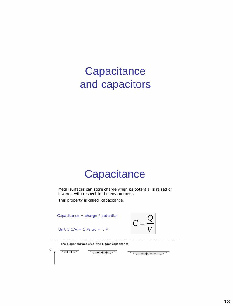
Capacitance
Metal surfaces can store charge when its potential is raised or lowered with respect to the environment.
This property is called capacitance.
V
QC
Capacitance = charge / potential
Unit 1 C/V = 1 Farad = 1 F
+ + + + + + + + + V
The bigger surface area, the bigger capacitance

14
Metal sphere capacitance
RV
QC 04
Q
R
Potential on the sphere is
Capacitance is thus
R
QV
04
Sphere’s capacitance is proportional to the radius.
Capacitors
• They store charge
• They are used in electrical devices:
• Radio , TV, phones, …
• Camera flash light
• Rectifiers, which transform AC to DC
• Low frequency filters
• Ultracapacitors in electric buses /vehicles
symbol

15
Plate capacitors
d
A
d
AC 0
voltage
U
capacitance : d
A
d
A
U
QC
Mostly there is insulator filling between plates
= dielectric constant of the insulator material
= Q/A = surface charge dens.
= 0 = permittivity of filling
E = / = electric field
U = E d = voltage
Energy density of the E-field
C
QCUQUW
22
2
1
2
1
2
1
AdEA
dAEW 2
21
222
21
Capacitor energy in three forms
For plate capacitor Q = A= EA ja C= A/d , whence
where Ad = V = volume between plates
Energy density of electric field
2
21 Ew unit : J/m3
Energy is usually = QU, but the
average charge during charging the
capacitor is ½ Q, => capacitor
energy = ½ QU

16
Cylindrical capacitor
)ln(
2
1
2
0
R
R
lC
Capacitance
l = length
r1 and r2 = radii of inner and
outer cylinder
0 = vacuum permittivity
= dielectric constant of
insulator
Cylindrical capacitors
Discharge through a resistor
R U C
charge discharge
I
Capacitor charge is Q = CU.
During the discharge the sum of voltages = 0
Q/C + R I = 0 where current I = Q’(t))
Charge and current drop exponentially. Product = CR is called time constant of the circuit and it gives the speed of discharge.
Solving this differential equation gives a mathematical discharge law:
RC
t
oeQQ
0.5 1.0 1.5 2.0 2.5 3.0
0.2
0.4
0.6
0.8
1.0

17
Capacitor connections
21
111
CCC
serial
21 CCC
parallel
Usage of capacitors:
* When we want a repeatedly identical current flow, capacitor discharge gives that
* examples: flash light, car ignition circuit
C1 C2
C2
C1
Other examples
LCf
2
1
We tune the radio receiver with an variable
capacitor.
In this old fashioned variable capacitor the
area A is varied by turning the knob
vrt. kaava
symbol
Variable capacitor
*) formula for received frequency
d
A
d
AC 0

18
Flash light
Large (in picture 185 F) capacitor is charged with
1,5 V battery and transformer circuit to high
voltage.
Capacitor discharge causes the flash
The energy released in the flash
light is given by W = ½ C U2
In the example 185F capacitor with 100
Volt gives energy
W = ½ 185*10-6*1002J = 1.9 J
Ultracapacitors
In city busses power source can be
ultracapacitor, which is charged at bus
stops.
Capacitance: 3000 F
life time: 10 years
Charging time : 1 - 10 sec
Range : 4 -5 blocks
Benefits:
low costs ( can save 200 000 € / year
good for environment
Ultracapacitor
buses in China.
19
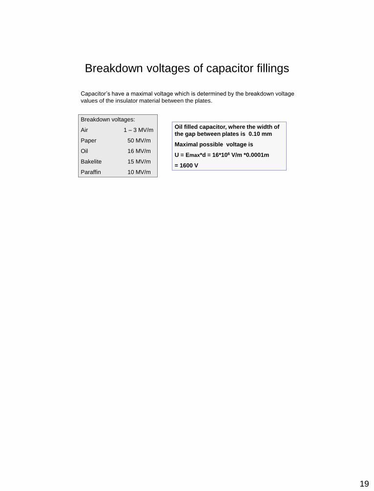
Breakdown voltages of capacitor fillings
Capacitor’s have a maximal voltage which is determined by the breakdown voltage
values of the insulator material between the plates.
Breakdown voltages:
Air 1 – 3 MV/m
Paper 50 MV/m
Oil 16 MV/m
Bakelite 15 MV/m
Paraffin 10 MV/m
Oil filled capacitor, where the width of
the gap between plates is 0.10 mm
Maximal possible voltage is
U = Emax*d = 16*106 V/m *0.0001m
= 1600 V
1
Magnetism
Magnetic force
Magnetic field B
History
• Already 500 eKr Greeks knew, that certain stones attract iron. These stones were magnetite FeO2 and they were found in province of Magnesia in Greece
• 1100 the Chinese made a compass from magnetite needles
• In 13th century was found that magnets have two poles P and S , P and S attracting each other but P and P and S and S repelling each other.
• It is not possible to isolate magnetic poles, electric poles can be isolated.
• 1500 Gilbert found out that the Earth is a big magnet and he made first magnetic maps of Earth

2
• Today magnetic poles are called “North”and “South” . The “N” of a magnet turns to the geographic North (which is thus magnetic
“South”)
• 1819 the Danish Ørsted noticed, that current affects magnetic needles
������ ���� ����
������ ���������� �������������� ����������� ���
� ������������������������������������������� � ���������������������� ��
� ��
Ørsted’s result
�
�
�������������������������������������������������
������������������������!�����"�����#���$���%������&�����������������
' �������������' (�������������������#�������������������������)��������������������������������������������

3
Other magnetic phenomena
• Magnetic field affects moving charges
• Between two currents exists a magnetic force
• Changes of magnetic field induce currents and EMF into wires
• Oscillating charges send EM waves
Magnetic force
)( BvqF���
×=
*����������������������������������������"�
+����������������������������������������"�
EqF��
⋅=
%
�
,
-
,�������������
,./%����-
0����������������������������������1 ���������"���������������
2����3�45�.� ����.�
Nikolai Tesla was an american engineer who invented first AC motor.

4
Magnetic force properties
1. Magnetic force is always perpendicular to the velocity => no work is done, kinetic energy is conserved
2. If the moving charge enters magnetic field in straight angle � =90o, its trajectory is a circle
3. If � � 90o , the velocity component in direction of magnetic field is conserved and orbit is spiral
������
������
������
-2-1
01
2
-2
-1
0
1
2
0
2
4
6
-2
-1
0
1
%
�
�
,
Cyclotron
qB
m
v
rT
⋅=
⋅=
ππ 22
5���������������������������������&�������������������
2���� ������������������
6������������������������%��������
6�����#��
����������78 �����������������������������������������������������������
��9������������"�������������������������������������������"�������������������������������
Orbit radius r
Period T does not depend on velocity
qB
mvr
r
mvqvB ==>=
2

5
“Magnetic shielding of the Earth”5������#�������������������#����������������*����)"�����%��������#����������#����� ��������*������#������������������ ����������,���1��#�����+��������#���������������
5�������������������:�������������#��������!:��������$
Northern lights
Corona discharge of the Sun emit
charged particles (Solar wind)
In the atmosphere these particles travel
along spiral trajectories following the
magnetic field lines to the poles.
They ionize the atoms of atmosphere and
visible light is emitted

6
Magnetic bottles
+������������������������������#����������&�#�����������������������������#���
DC motors
DC motors are based on the magnetic force acting on current loops

7
����������
����������
����������;
,����������< ��%�����#���%���������
� ������, .�/ %�)������������������������������
� ,.= %� �/ .= ;�%�� .= ;���.;�>
,
IBLF =
�������� ���������� ��
�������� ����� ��
������� � ���
!������������� �� ����� ���
Magnetic force on a wire
If the current wire comes at angle � to the magnetic field, the force is
F = IBL sin�
Torque on a current loop or coil
�
;
�
"
,
,
�������,�����#���������"����������,.�;"
�������#�������������/��� .?�;"�4?.@
.�;�)������.�" !���#����$
(���������#����#������������������3��������)
�����1�������/����!������#���������#������#�������$
��1 .3�;�

8
Torque depends on the angle �
������
�,
,
αsinNBIAT =
��/��������������������������������3��������)�����)�������;��
� .�����"������������������������������������
�
DC motor
�������������/�� �������������)
-6 -4 -2 2 4 6
0.2
0.4
0.6
0.8
1 �����������/�����������%���
commutator
9
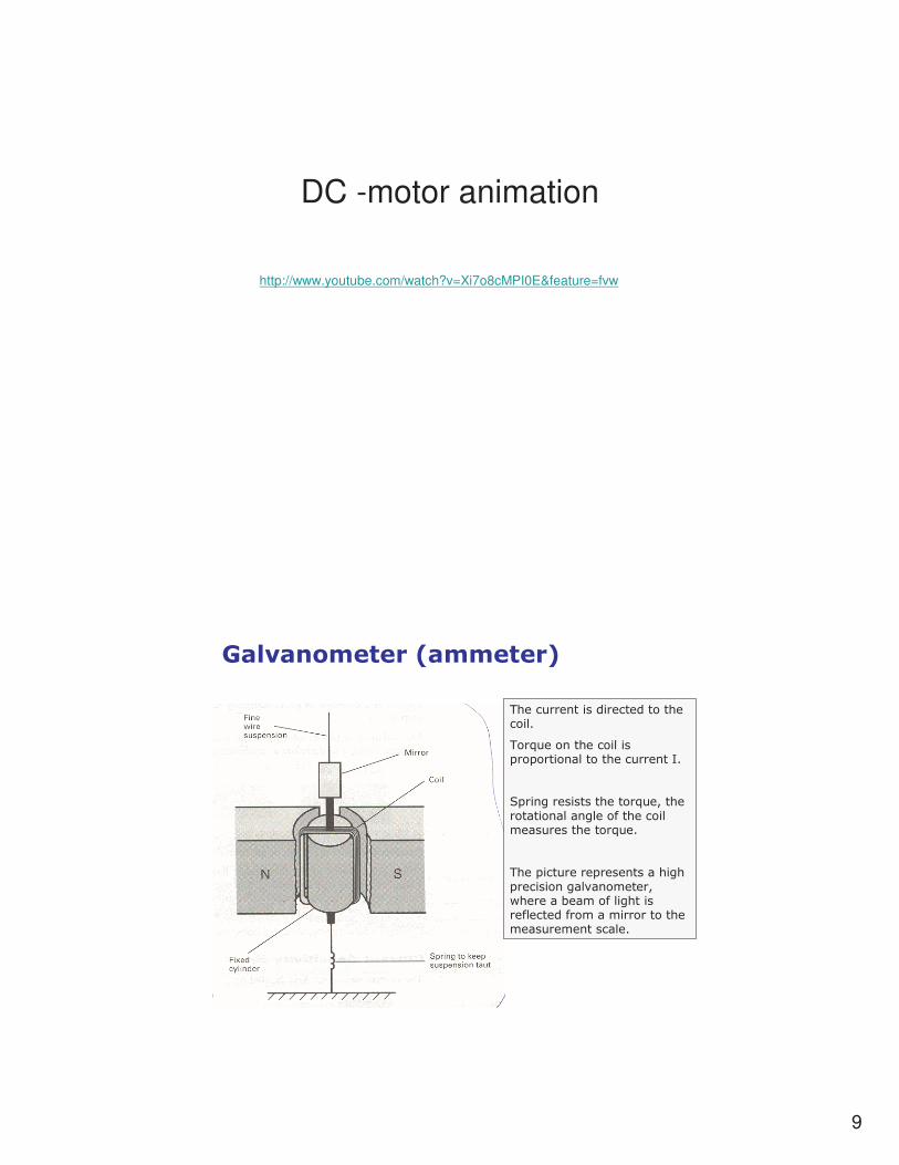
DC -motor animation
http://www.youtube.com/watch?v=Xi7o8cMPI0E&feature=fvw
�����������������
�����������������������������
��/�������������#��#��������������������;�
:#�����������������/��)�����������������������������������������/���
��#��������#������������#�����������%��������)������"������������������������������������������������������
10
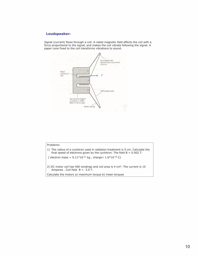
�����������
:�����!�������$��������������������������������������������������������������#��#�������������������)�����&���������%�"������������������������#�#��������1���������������������%�"���������������
F
6��"����
�$ ��������������������������������������������������5�����������������#����������������%��"�������������� ��������.����? �
!������������.A���B��C� &�)������.��DB���A 5$
?$75������������E�����������������������E��?� ���������������#�����5���������.C�� �
5������������������$��1�������/��"$�������/���

11
Origin of magnetic field
Biot- Savart law
Ampere’s law
���A7��������A7�����FF���������� �"���%��)��������"���%��)�������������������������������#���������������������������������#���������
��,��������� ���:�%��� �����%������?�����)���������#����"���������������������������
Magnetic field

12
Biot- Savart’s law (1820)
-
���������������������������)�����������;�����������������#����6�������������������� �������"����������������������������-
2
0
4
sin
r
lIdB
⋅
∆=
π
αµ
:���������
G�.E�B���
�������������������#�����"�������%�����
The field of a straight wire
dxRx
R
Rx
IB
2222
0
)(4 ++= �
∞
∞−π
µ
-
R
IB
⋅=
π
µ
2
0
;������������������� :�%��� ����%���������������������1 ��%��
H����� �����������������
���-
�!1?IH?$

13
Field in the middle of a loop
2
0
2
0
2
0
4
2
44 r
rIdl
r
I
r
IdlB
⋅
⋅=
⋅=
⋅= �� π
πµ
π
µ
π
µ
�
;
���� :�%��� ��%������������
r
IB
2
0µ=
,�����������������������#
�����������
Ampere’s law
��#�������%���������� :�%���J� ����������)�/��%��������)��������������������������������������
� =⋅ IldB 0µ��
��#���J����
������CD
�
���������������������������%������������#.�����������������������#�������������������
��#���

14
Ampere’s laws applications
;
�
����#���J�������������%�������������������������#��#������
�?� �.G� ;)������
r
IB
⋅=
π
µ
2
0��:����������������
?�5���J��������������
5���������>
3������������3
�������������������������������������������"��)��#���J��������������%�����������%����>�5������#������������������%�����3�����!��������������$
NIBL 0µ=
.@,�������������������������������
L
NIB 0µ
=
"������ �� ������������!������������� �

15
Summary of laws:
� =⋅ IldB 0µ��
+��������������������"���������������"�������������������
2
0 sin
r
lIdB
αµ ∆=���� :�%���J� ���
��#���J����
Right hand rules�������
+�����������������
;�������������������"���������������������)���������������������������������������������

16
Magnetic Induction
Magnetic flux
Lenz law
History
Faraday invented induction in his
experiment 1831.
Turning current on or off in the primary coil makes the ammeter pointer swing.
But when the current has been on for a while, ammeter shows zero.
Conclusion is that, inductive current is seen only when the magnetic field is changing, but not when the magnetic field is constant.
Modern society with electric energy is based on induction.
17
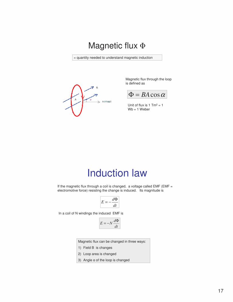
Magnetic flux �
Magnetic flux through the loop is defined as
αcosBA=Φ
Unit of flux is 1 Tm2 = 1 Wb = 1 Weber
= quantity needed to understand magnetic induction
Induction law
dt
dE
Φ−=
If the magnetic flux through a coil is changed, a voltage called EMF (EMF = electromotive force) resisting the change is induced. Its magnitude is
In a coil of N windings the induced EMF is
dt
dNE
Φ−=
Magnetic flux can be changed in three ways:
1) Field B is changes
2) Loop area is changed
3) Angle � of the loop is changed
18
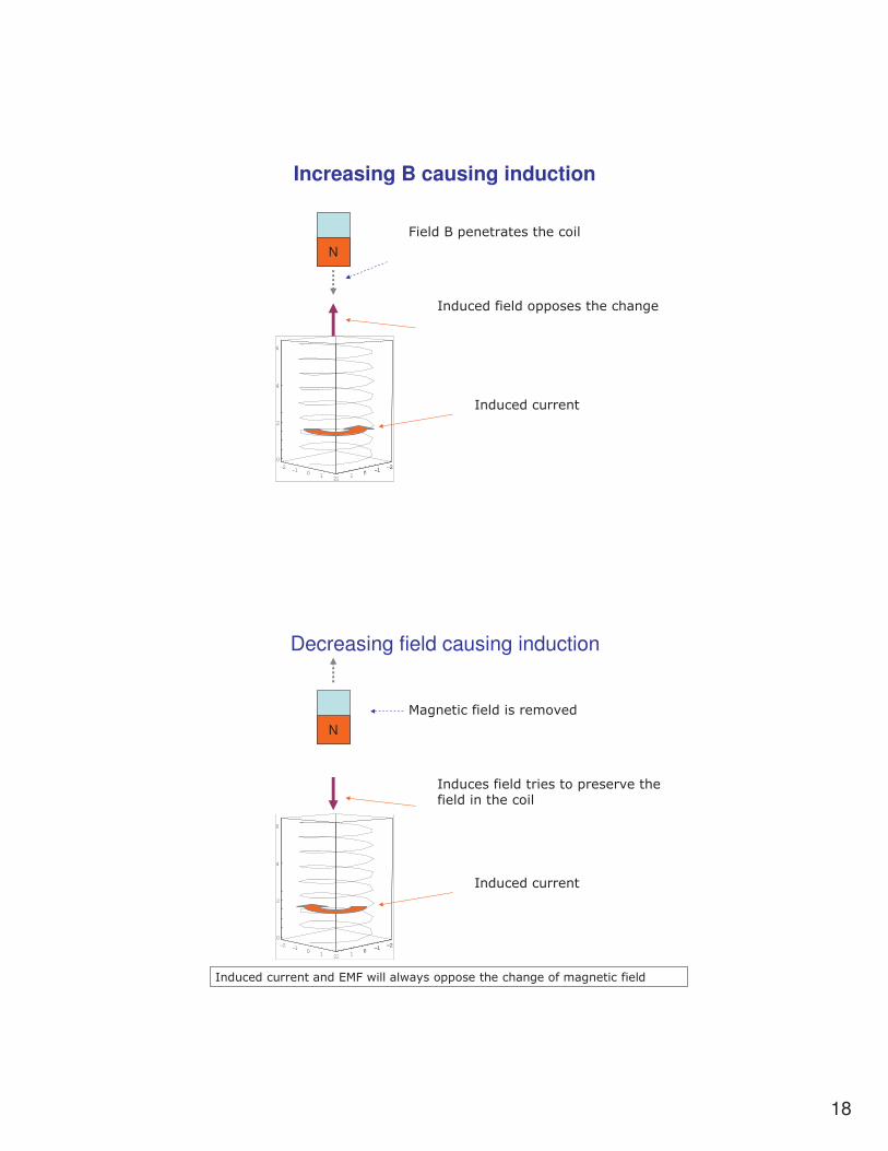
Increasing B causing induction
-2-1
01
2
-2-1
01
2
0
2
4
6
-2-1
01
N
,�����#����������������
;������������##�������������
;�������������
Decreasing field causing induction
-2-1
01
2
-2-1
01
2
0
2
4
6
-2-1
01
N
+������������������%��
;������������������#�����%������������������
;�������������
;����������������*+,�����������##���������������������������
19
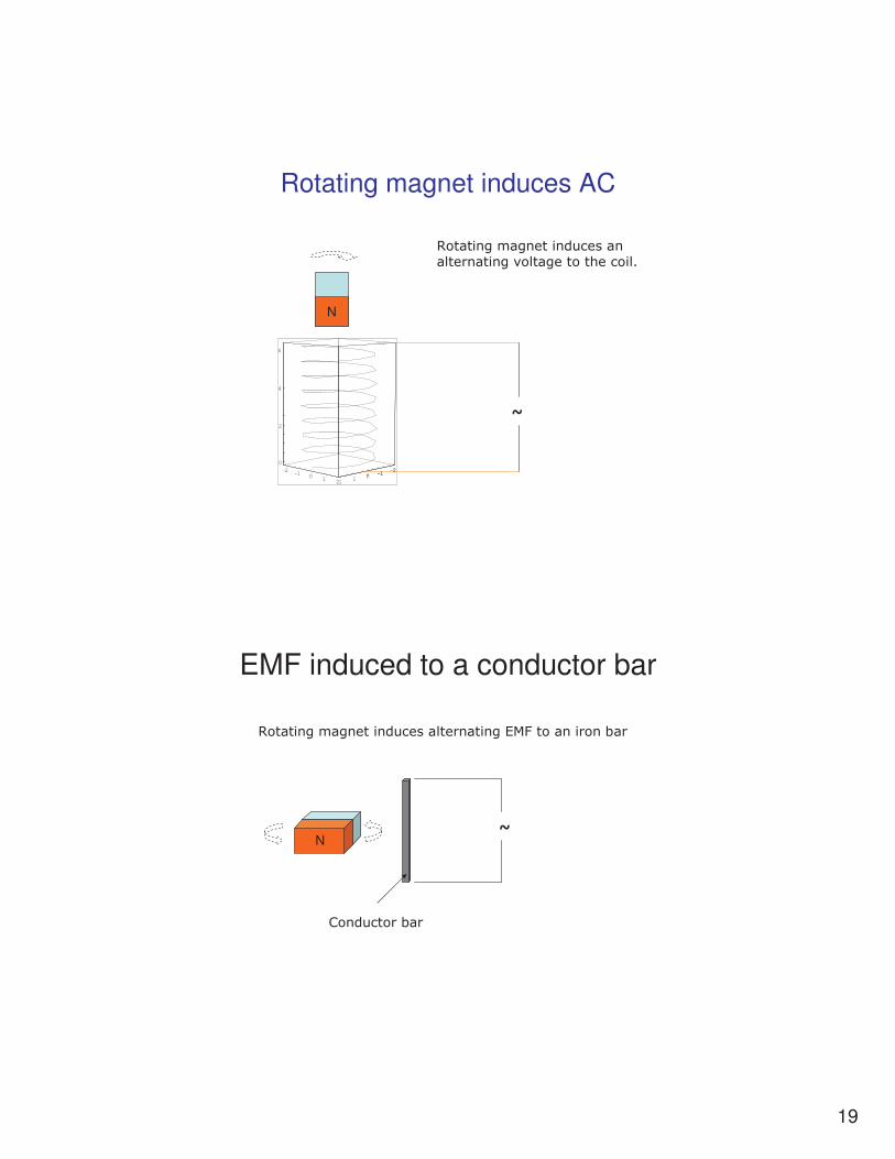
Rotating magnet induces AC
-2-1
01
2
-2-1
01
2
0
2
4
6
-2-1
01
N
�
H���������������������������������%����������������
EMF induced to a conductor bar
H�������������������������������*+,��������"��
5��������"��
�N

20
Generator of hydroelectric power plant
3
3
3
3
3
3
:
:
:
:
:
:
:
:
:
:
:
:
:
:
:
:
:
:
3
3
3
3
3
3
3
3
3
3
3
3
(������������"����������������������������������������������� �������������������������������������������*+,�����"��
;���"��
� �5
�����������������������
3 :
5���������������/������
������������� ��� � ��������� !�"�������� #�$ ���� !�%��
����������� �����&���$� ����������'�(���������������
'�!�) *���+�� !�) *�,�"����� ��
!- '!���*"�������
tee ωsinˆ= where peak voltage is ê = �NBA

21
Bicycle dynamo
In a dynamo the rotating magnet is called the anchor and the coil is called the stator.
Eddy currents
N
+������������#�����������������#����
.@�����������������������;���������������������������#��%������#����������
;�����������������

22
Moving eddy current
N
+�������%�������
*������������%�������
�
�����������������#�����������"���������������������#�����(�����������������##��)������������������������ ����������������##����
Magnetic train
������������#�����"�������#����� ������������������������������������(�������������%��)�����������������������������������%��������������������������������

23
Next topics
• Magnetic materials• Self induction• Coils , inductance• Transformers• Three phase currents• Electromagnetic waves
Magnetic materials
In a medium the magnetic field B usually becomes stronger ( para- and ferromagnetism) , in some cases weaker (diamagnetism).
The vacuum permeability �0 gets in formulas a multiplier coefficient � , which is called the relative permeability of the material.
l
NIB 0
κµ=F.e a coil with an iron core has a
magnetic field given by
B0 B= � B0

24
Diamagnetic Paramagnetic Ferromagnetic materials
materials materials
Au, Cu, Pb, N2, Si
� < 1
* Magnetic field slightly smaller than in the air
* The magnetic dipole moments of atoms turn against the external field for reasons that can be explained only through quantum theory
Al, Ca, O2, Pt
� > 1
*Magnetic field slightly greater than in the air
•The atoms are small magnets, because the electron orbits are current loops
• The atoms turn to the direction of outside field
Fe, Ni, Co
� = 400 - 2000
* Magnetic field much greater than in the air
•Small magnetic domains turn in external field to the same direction=> becomes a permanent magnet
• Above Curie –temperature (Iron 1043K) is not magnetized
Often is written � = 1 + � where
� is called the susceptibility of the material
Self induction
2 4 6 8 10
1
2
3
4
5
6
time
current
LE
1
2
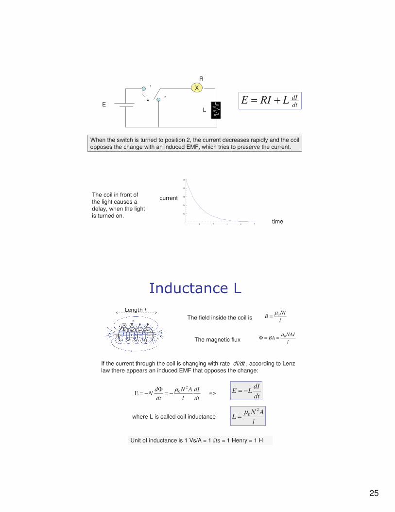
dtdILRIE +=
X
R
Self induction: When the switch is turned to position 1, the increase of current changes the magnetic flux in the coil => The coil reacts to the change with an induced EMF, which tries to prevent the change.
The coil in front of the light causes a delay, when the light is turned on.
25
time
current
LE
1
2
dtdILRIE +=
X
R
When the switch is turned to position 2, the current decreases rapidly and the coil opposes the change with an induced EMF, which tries to preserve the current.
The coil in front of the light causes a delay, when the light is turned on.
1 2 3 4 5
0.2
0.4
0.6
0.8
1.0
;���������>
>����� �
l
NIB 0
µ=The field inside the coil is
The magnetic flux l
NAIBA 0
µ==Φ
If the current through the coil is changing with rate dI/dt , according to Lenz law there appears an induced EMF that opposes the change:
dt
dI
l
AN
dt
dN
2
0µ
−=Φ
−=Ε
where L is called coil inductance
dt
dILE −=
Unit of inductance is 1 Vs/A = 1 �s = 1 Henry = 1 H
=>
l
ANL
2
0µ
=

26
Coil energy
The energy stored in the magnetic field of the coil
2
2
1LIW =
R
Car
battery
switch
resistance of the circuit
spark plug
secondary coil
CAR IGNITION SYSTEM
When the switch is turned on, the current will reach the value E/R in time, which is given by L/R (time constant)
When the current is cut off, the time constant is very low, because the resistance in L/R will be extremely large. So dI/dt will be very large and also the induced voltage in the primary coil will be very large: maybe 100 V or more.
This induced peek is however magnified with a transformer ( 1:10 or 1:20) to
10 kV – 20 kV peek, which will create a spark in the plug.
see the end of MIT lecture #24 (end)
Problem: Assume that the primary coil has an inductance L = 2 H and the total resistance of the primary circuit is 6 ohms.
Calculate the energy of the spark.

27
Relay
A small control current in coil terminals will close the main circuit.
(Example: garage doors, alarm systems )
Microphone
sound
The sound waves cause vibrations in the paper foil and the magnet fixed in it.
The vibrations of the magnet cause induced EMF in the coil, which can be amplified.
A microphone modulates 9V DC. A capacitor is used to filter the DC off.
out
micro-
phone

28
Thief alarm systems
There are magnets fixed to the products. The magnet causes an induction current in the coils of the gate and causes an alarm.
A gate with induction coils
Electromagnets

29
Metal detectors
An alternating current generates a time-varying magnetic field around the coil.
This field induces eddy currents in a nearby metal object which, in turn, generate a time-varying magnetic field of their own.
These fields induce a voltage in the receive coil which, when amplified, reveal the presence of the metal object or target
sending coilreceiving coil
Metal object with induced eddy current and induced field
Transformers
Np windings Ns windings
Up
Us
Current Is
Current Ip
(made of isolated plates of iron to prevent eddy currents)
30
l
IN
l
INB sspp 00 µµ
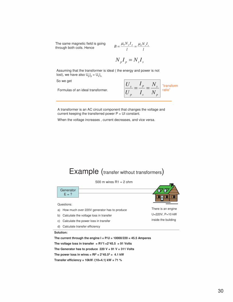
==The same magnetic field is going through both coils. Hence
sspp ININ =
Assuming that the transformer is ideal ( the energy and power is not lost), we have also UpIp = UsIs.
So we get
p
s
s
p
p
s
N
N
I
I
U
U==Formulas of an ideal transformer.
A transformer is an AC circuit component that changes the voltage and current keeping the transferred power P = UI constant.
When the voltage increases , current decreases, and vice versa.
”transform ratio”
Example (transfer without transformers)
GeneratorE = ?
500 m wires R1 = 2 ohm
There is an engine
U=220V, P=10 kW
inside the building
Questions:
a) How much over 220V generator has to produce
b) Calculate the voltage loss in transfer
c) Calculate the power loss in transfer
d) Calculate transfer efficiency
Solution:
The current through the engine I = P/U = 10000/220 = 45.5 Amperes
The voltage loss in transfer = R1*I =2*45.5 = 91 Volts
The Generator has to produce 220 V + 91 V = 311 Volts
The power loss in wires = RI2 = 2*45.52 = 4.1 kW
Transfer efficiency = 10kW /(10+4.1) kW = 71 %

31
Example (transfer with transformers)
GeneratorE = ?
500 m wires R1 = 2 ohm
There is an engine
U=220V, P=10 kW
inside the building
Solution:
The current through the engine I = P/U = 10000/220 = 45.5 Amperes
The current in the wires I1 = 1/20 * 45.5 A = 0.455 A
The voltage loss in transfer = R1*I1 =2*0.455 =0. 91 Volts
The Generator has to produce 220 V + 0.91 V = 221 Volts
The power loss in wires = RI2 = 2*0.4552 = 0.41 W
Transfer efficiency = 10000W /(10000.41) W = nearly 100 %
M1 M2
1:2020:1
In practice the transformers do heat => there is loss of energy inside transformers.
Transfer of electric energy
Principal lines : 400 kV or 220 kV
Major lines: 110 kV
Local lines: 20 kV or 10 kV
Consumer lines: 220 V
Finland

32
Three phase current
Most alternating-current (AC) generation and transmission, and a good part of use, take place through three-phase circuits. If you want to understand electric power, you must know something about three-phase.
Benefits of three phase current1) If the loads of all phases are equal (as it
should be the case), the current in the fourth (neutral wire) is zero, which decreases the transfer losses in wires.
2) The system gives two different voltages: A) the phase voltage V between one face and the neutral wire
B) higher voltage between two phases, which is �3 V
3) Three phase system makes it possible to build three phase motors(*), which are based on the circulating magnetic field that three phase voltage creates.
(*)look MIT video #18

33
Electromagnetic waves
1864 Maxwell predicted the existence of electromagnetic waves when he derived the following wave equation from the Maxwell equations:
2
2
22
21
x
E
ct
E
∂
∂=
∂
∂ the speed of light in vacuum
c = 1/�(0�0) = 300Mm/s
(one dimensional wave equation)
A German physicist Heinrich Hertz made 1887 an experiment that proved the existence of electromagnetic waves.
The solution is any function of form E = f (x – c t). The solution represents a wave traveling at the speed of c.
Electric field and magnetic field oscillate perpendicular to each other. The changing electric field creates always a magnetic field and vice versa.

34
Spectrum of EM waves
Gamma rays
X - rays
UV
Visible light
IR
Microwaves
Radio waves
9/5/2014
1
AC circuits
1. Resistance, capacitance and inductance in AC 2. Impedance Z, phase 3. Power in AC circuits
Apparent power S Real power P Reactive power Q
Resistance and AC
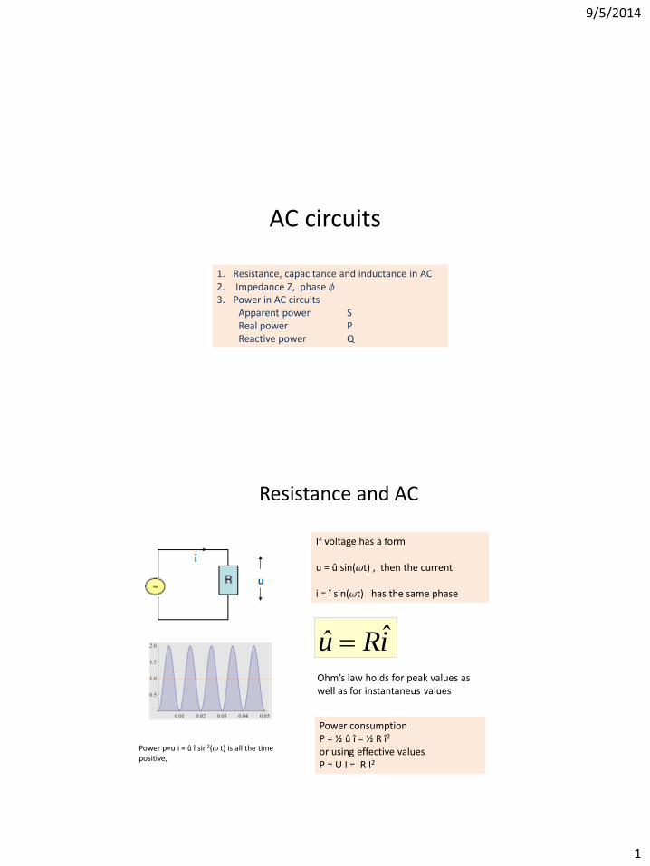
If voltage has a form u = û sin(t) , then the current i = î sin(t) has the same phase
iRu ˆˆ Ohm’s law holds for peak values as well as for instantaneus values
Power consumption P = ½ û î = ½ R î2
or using effective values P = U I = R I2
Power p=u i = û î sin2( t) is all the time positive,

9/5/2014
2
Capacitance and AC
If current has form i = î sin(t) then voltage phase is 90o behind u = -û cos(t)
iC
iXu ˆ1ˆˆ
(analogy to Ohm’s law)
Real power consumption = 0
X = reactance
Power oscillates around zero. Average power = 0. It is called ”reactive power”. Phase = -90o
Inductance (coil) and AC
If current has form i = î sin(t) then voltage is 90o ahead u = û cos(t)
iLiXu ˆˆˆ
(analogy to Ohm’s law)
X = L (reactance)
Power oscillates around zero. Average power = 0. It is called ”reactive power”. Phase = +90o
Real power consumption = 0
9/5/2014
3
All three together in AC circuit
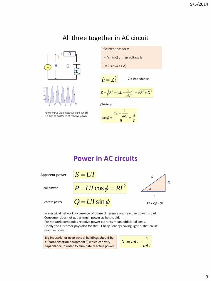
If current has form i = î sin(t) , then voltage is u = û sin( t + )
iZu ˆˆ Z = impedance
2222 )1
( XRC
LRZ
R
X
R
CL
1
tan
phase
Power curve visits negative side, which is a sign of existence of reactive power
Power in AC circuits
2cos RIUIP
UIS
sinUIQ
Real power
Apparent power
Reactive power
P
Q
S
P2 + Q2 = S2
In electrical network, occurence of phase difference and reactive power is bad . Consumer does not get as much power as he should. For network companies reactive power currents mean additional costs. Finally the customer pays also for that. Cheap ”energy saving light bulbs” cause reactive power.
CLX
1
Big industrial or even school buildings should by a ”compensation equipment ”, which can vary capacitance in order to eliminate reactive power.
9/5/2014
4
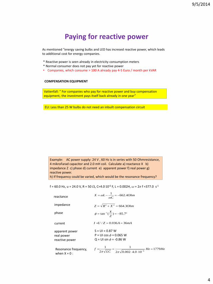
Paying for reactive power
As mentioned ”energy saving bulbs and LED has incresed reactive power, which leads to additional cost for energy companies.
* Reactive power is seen already in electricity consumption meters * Normal consumer does not pay yet for reactive power • Companies, which consume > 100 A already pay 4-5 Euro / month per kVAR
COMPENSATION EQUIPMENT
Vattenfall: ” For companies who pay for reactive power and buy compensation equipment, the investment pays itself back already in one year”
EU: Less than 25 W bulbs do not need an inbuilt compensation circuit
Example: AC power supply: 24 V , 60 Hz is in series with 50 Ohmresistance, 4 mikroFarad capacitor and 2.0 mH coil. Calculate a) reactance X b) impedance Z c) phase d) current e) apparent power f) real power g) reactive power. h) If frequency could be varied, which would be the resonance frequency?
OhmC
LX 4.6621
f = 60.0 Hz, u = 24.0 V, R = 50 , C=4.0.10-6 F, L = 0.002H, = 2 f =377.0 s-1
OhmXRZ 3.66422
reactance
impedance
phase 7.85)(tan 1
Z
X
current mAAZUI 36036.0/
apparent power real power reactive power
S = UI = 0.87 W P = UI cos = 0.065 W Q = UI sin = -0.86 W
Resonance frequency, when X = 0 :
HzHzLC
f 1779100.4002.02
1
2
1
6